JP2015169491A - Displacement detector and displacement detection method - Google Patents
Displacement detector and displacement detection method Download PDFInfo
- Publication number
- JP2015169491A JP2015169491A JP2014043576A JP2014043576A JP2015169491A JP 2015169491 A JP2015169491 A JP 2015169491A JP 2014043576 A JP2014043576 A JP 2014043576A JP 2014043576 A JP2014043576 A JP 2014043576A JP 2015169491 A JP2015169491 A JP 2015169491A
- Authority
- JP
- Japan
- Prior art keywords
- light
- retroreflector
- beam splitter
- displacement
- unit
- Prior art date
- Legal status (The legal status is an assumption and is not a legal conclusion. Google has not performed a legal analysis and makes no representation as to the accuracy of the status listed.)
- Pending
Links
Images


Landscapes
- Length Measuring Devices By Optical Means (AREA)
Abstract
Description
本発明は、変位検出装置および変位検出方法に関する。 The present invention relates to a displacement detection device and a displacement detection method.
従来、被測定物の変位を検出する装置が知られている(例えば、特許文献1参照)。
特許文献1には、レーザートラッカーが開示されている。レーザートラッカーは、被測定物に設けられた1つのターゲットを移動させ、このターゲットをレーザ光で追尾する。そして、ターゲットからの反射光に基づくターゲットまでの距離と、ターゲットの空間的な角度とに基づいて、被測定物の変位を検出している。
Conventionally, an apparatus for detecting the displacement of an object to be measured is known (for example, see Patent Document 1).
Patent Document 1 discloses a laser tracker. The laser tracker moves one target provided on the object to be measured, and tracks this target with laser light. The displacement of the object to be measured is detected based on the distance to the target based on the reflected light from the target and the spatial angle of the target.
しかしながら、特許文献1に記載のような構成では、ターゲットを追尾するための機構が必要となり、構成が複雑となってしまうと言う問題点がある。 However, the configuration as described in Patent Document 1 requires a mechanism for tracking the target, and there is a problem that the configuration becomes complicated.
本発明の目的は、簡単な構成で被測定物の変位を検出できる変位検出装置および変位検出方法を提供することにある。 An object of the present invention is to provide a displacement detection device and a displacement detection method capable of detecting the displacement of an object to be measured with a simple configuration.
本発明の変位検出装置は、被測定物に設けられた再帰性反射体と、前記再帰性反射体に向けて、所定範囲を照射可能な照射光を出射する光源部と、前記再帰性反射体と前記光源部との間に設けられ、前記照射光を透過するとともに、前記再帰性反射体で反射された光を反射するビームスプリッタと、前記ビームスプリッタで反射された光を受光する受光部とを備えていることを特徴とする。
本発明の変位検出方法は、被測定物に設けられた再帰性反射体に向けて、所定範囲を照射可能な照射光を光源部から出射し、前記再帰性反射体と前記光源部との間に設けられたビームスプリッタによって、前記照射光を透過するとともに、前記再帰性反射体で反射された光を反射し、このビームスプリッタで反射された光を受光部で受光し、この受光部での受光位置に基づいて、前記被測定物の変位を検出することを特徴とする。
The displacement detection apparatus of the present invention includes a retroreflector provided on a measurement object, a light source unit that emits irradiation light that can irradiate a predetermined range toward the retroreflector, and the retroreflector. A beam splitter that transmits the irradiation light and reflects the light reflected by the retroreflector, and a light receiving unit that receives the light reflected by the beam splitter. It is characterized by having.
The displacement detection method of the present invention emits irradiation light that can irradiate a predetermined range from a light source unit toward a retroreflector provided on an object to be measured, and between the retroreflector and the light source unit. The beam splitter provided on the light beam transmits the irradiation light, reflects the light reflected by the retroreflector, and receives the light reflected by the beam splitter by the light receiving unit. The displacement of the object to be measured is detected based on a light receiving position.
本発明の別の変位検出装置は、被測定物に設けられた再帰性反射体と、所定範囲を照射可能な照射光を出射する光源部と、前記光源部に対して前記照射光の出射側に設けられ、前記照射光を反射して前記再帰性反射体に入射させるとともに、前記再帰性反射体で反射された光を透過するビームスプリッタと、前記ビームスプリッタを透過した光を受光する受光部とを備えていることを特徴とする。
本発明の別の変位検出方法は、被測定物に設けられた再帰性反射体に向けて、所定範囲を照射可能な照射光を光源部から出射し、前記光源部に対して前記照射光の出射側に設けられたビームスプリッタによって、前記照射光を反射して前記再帰性反射体に入射させるとともに、前記再帰性反射体で反射された光を透過し、このビームスプリッタを透過した光を受光部で受光し、この受光部での受光位置に基づいて、前記被測定物の変位を検出することを特徴とする。
Another displacement detection apparatus according to the present invention includes a retroreflector provided on an object to be measured, a light source unit that emits irradiation light that can irradiate a predetermined range, and an emission side of the irradiation light with respect to the light source unit. A beam splitter that reflects the irradiated light to enter the retroreflector and transmits the light reflected by the retroreflector, and a light receiving unit that receives the light transmitted through the beam splitter It is characterized by having.
According to another displacement detection method of the present invention, irradiation light capable of irradiating a predetermined range is emitted from a light source unit toward a retroreflector provided on an object to be measured, and the irradiation light is emitted to the light source unit. A beam splitter provided on the exit side reflects the irradiated light to enter the retroreflector, transmits the light reflected by the retroreflector, and receives the light transmitted through the beam splitter. And detecting the displacement of the object to be measured based on the light receiving position at the light receiving portion.
このような構成によれば、再帰性反射体に対して出射された照射光は、ビームスプリッタを透過した後、再帰性反射体で反射する。再帰性反射体で反射した光は、ビームスプリッタに戻り、このビームスプリッタで反射した後、受光部で受光される。
また、別の構成によれば、光源部から出射された照射光は、ビームスプリッタで反射して再帰性反射体に入射する。再帰性反射体に入射した光は、この再帰性反射体で反射して、ビームスプリッタに戻り、このビームスプリッタを透過した後、受光部で受光される。
そして、照射光の照射範囲において、再帰性反射体が照射光の光軸と直交する方向に移動すると、受光位置は、再帰性反射体の移動に対応して変位する。
このため、再帰性反射体を追尾する構成を設けることなく簡単な構成で、照射範囲で移動する再帰性反射体の位置に基づいて、被測定物の変位を検出することができる。
According to such a configuration, the irradiation light emitted to the retroreflector is reflected by the retroreflector after passing through the beam splitter. The light reflected by the retroreflector returns to the beam splitter, is reflected by the beam splitter, and is received by the light receiving unit.
Moreover, according to another structure, the irradiation light radiate | emitted from the light source part reflects in a beam splitter, and injects into a retroreflection body. The light incident on the retroreflector is reflected by the retroreflector, returns to the beam splitter, passes through the beam splitter, and is received by the light receiving unit.
When the retroreflector moves in a direction orthogonal to the optical axis of the irradiation light in the irradiation range of the irradiation light, the light receiving position is displaced corresponding to the movement of the retroreflector.
For this reason, the displacement of the object to be measured can be detected based on the position of the retroreflector that moves in the irradiation range with a simple configuration without providing a configuration for tracking the retroreflector.
本発明の変位検出装置において、前記ビームスプリッタと前記受光部との間に設けられ、前記ビームスプリッタからの光を集光する集光部を備えていることが好ましい。 In the displacement detection apparatus of the present invention, it is preferable that the displacement detection apparatus further includes a light collecting unit that is provided between the beam splitter and the light receiving unit and collects light from the beam splitter.
このような構成によれば、集光部を設けない構成と比べて、受光部での受光スポットのサイズを小さくすることができ、被測定物の変位検出精度を向上させることができる。また、受光スポットを小さくすることができるため、変位検出範囲を広げることができる。 According to such a configuration, it is possible to reduce the size of the light receiving spot at the light receiving unit, and to improve the displacement detection accuracy of the object to be measured, compared to a configuration in which the light collecting unit is not provided. In addition, since the light receiving spot can be reduced, the displacement detection range can be expanded.
[第1実施形態]
以下、本発明の第1実施形態について説明する。
{ステージ装置の構成}
まず、本発明の第1実施形態に係るステージ装置の構成について説明する。
なお、図1では、互いに直交する3軸をX軸、Y軸およびZ軸とし、紙面上下方向をZ軸方向として説明する。なお、当該X軸方向、Y軸方向およびZ軸方向により、マシン座標系が規定される。以下の図面においても同様である。
[First Embodiment]
The first embodiment of the present invention will be described below.
{Stage device configuration}
First, the configuration of the stage apparatus according to the first embodiment of the present invention will be described.
In FIG. 1, three axes that are orthogonal to each other will be described as an X axis, a Y axis, and a Z axis, and the vertical direction on the paper surface will be described as a Z axis direction. The machine coordinate system is defined by the X-axis direction, the Y-axis direction, and the Z-axis direction. The same applies to the following drawings.
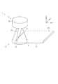
ステージ装置1は、図1および図2に示すように、ステージ本体2と、変位検出装置3と、制御装置4とを備えている。
As shown in FIGS. 1 and 2, the stage device 1 includes a
ステージ本体2は、被測定物としてのXYステージ21と、XYステージ21をX軸方向およびY軸方向にスライドさせるスライド機構22と、スライド機構22を駆動する駆動部23とを備えている。
XYステージ21は、四角形板状に形成されており、XY平面と略平行な載置面211を有している。この載置面211には、ステージ装置1により位置決めされる図示しない位置決め対象物が載置される。
スライド機構22は、例えば、図示しないスライダ、ガイドレールなどにより構成されている。
The
The
The
変位検出装置3は、XYステージ21のX軸方向およびY軸方向の位置を検出する。変位検出装置3は、図1および図3に示すように、再帰性反射体31と、光源部32と、ビームスプリッタ33と、受光部34と、集光部35と、光源制御部36と、変位演算部37とを備えている。
The
再帰性反射体31は、XYステージ21における載置面211の所定の位置、例えば角部に設けられている。再帰性反射体31は、入射する光を反射して、この入射した方向に戻す。再帰性反射体31としては、屈折率が2のボールレンズ311における光の入射方向と反対側の半球面に、全反射膜312をコーティングした構成が例示できる。また、再帰性反射体31としては、3枚の平板を直角に組み合わせることで立方体の頂点型に形成し、その内面に全反射膜を設けたいわゆるコーナーキューブであってもよい。
The
光源部32、ビームスプリッタ33、受光部34および集光部35は、XYステージ21の上方に配置された筐体30に収容されている。
光源部32は、再帰性反射体31に向けて、所定範囲を照射可能な照射光L1を出射する。光源部32は、光源制御部36により制御され、発散光を照射光L1として出射する光源321を備えている。光源321は、照射光L1の光軸(中心軸)LAがZ軸と略平行となるように配置されている。なお、光源321は、光軸LAがZ軸と交差するように配置されていてもよい。また、光源321は、XYステージ21に設けられた再帰性反射体31が移動可能な全範囲を含む円形状の照射範囲Aを、照射光L1が照射可能なように配置されている。
The
The
ビームスプリッタ33は、再帰性反射体31と光源部32との間に設けられ、照射光L1を透過するとともに、再帰性反射体31で反射された反射光L2を反射する。ビームスプリッタ33としては、ハーフミラー、プリズムなどを用いることができる。
The
受光部34は、集光部35から出射される後述する集光光L4を受光面341で受光し、この受光位置に対応する信号を制御装置4へ出力する。受光部34としては、二次元PSD(Position Sensitive Detector(光位置センサ))、CMOS(Complementary MOS(Metal-Oxide Semiconductor))イメージセンサ、CCD(Charge Coupled Device)イメージセンサ、PD(Photodiode)アレイなどを用いることができる。
The
集光部35は、ビームスプリッタ33と受光部34との間に設けられ、ビームスプリッタ33で反射された反射光L3を集光し、その集光光L4を出射する。集光部35は、焦点が受光面341上に位置するように配置された集光レンズ351で構成されている。このため、受光面341における集光光L4の受光スポットSP1は、点状となる。
The condensing
ここで、光源321と、ビームスプリッタ33と、集光レンズ351との位置関係について詳細に説明する。
まず、図4に示すように、ビームスプリッタ33における反射光L2の反射面において、照射光L1の光軸LAが通る位置を交点Pとする。集光レンズ351は、当該集光レンズ351における主面351Aの中心351Cと交点Pとを結ぶ線分M1が、光源321の発光点321Aと交点Pとを結ぶ線分M2と直交するように配置されている。また、集光レンズ351は、線分M1の長さと線分M2の長さとが等しくなるように配置されている。
このような配置によって、再帰性反射体31の位置にかかわらず、反射光L3の光軸が主面351Aの中心351C上に位置し、反射光L3の光軸上の光は、集光レンズ351において屈折せずに真っ直ぐに進行して、受光面341に到達する。したがって、受光面341における受光位置と、再帰性反射体31の位置とを正確に対応させることができる。
Here, the positional relationship among the
First, as shown in FIG. 4, the intersection point P is a position where the optical axis LA of the irradiation light L1 passes on the reflection surface of the reflection light L2 in the
With such an arrangement, regardless of the position of the
なお、例えば、線分M1の長さと線分M2の長さとが等しくならないように、光源321と、ビームスプリッタ33と、集光レンズ351を配置した場合、再帰性反射体31の位置によっては、反射光L3の光軸が中心351Cから外れた位置に位置し、反射光L3の光軸上の光は、集光レンズ351において屈折して受光面341に到達する。このような場合、受光面341における受光位置と、再帰性反射体31の位置とが正確に対応しなくなってしまうが、変位演算部37において補正処理を行うことによって、適切に変位を演算することができる。
For example, when the
光源制御部36は、光源部32の光源321を制御して、照射光L1を出射させる。
変位演算部37は、受光部34での集光光L4の受光位置に基づいて、XYステージ21の変位を演算する。
The light
The
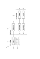
制御装置4は、図2に示すように、駆動部23を制御してXYステージ21を移動させる駆動制御部41を備えている。なお、光源制御部36および変位演算部37は、制御装置4の一部を構成している。
As shown in FIG. 2, the control device 4 includes a
{ステージ装置による位置調整方法}
次に、ステージ装置1による位置調整方法について説明する。
まず、XYステージ21が所定位置に位置している状態で、光源制御部36は、光源321に照射光L1を出射させる。このとき、XYステージ21上の再帰性反射体31が移動可能な全範囲が、照射光L1の照射範囲Aに含まれているため、XYステージ21がいかなる位置に移動しても、再帰性反射体31に照射光L1が照射される。
{Position adjustment method by stage device}
Next, a position adjustment method using the stage device 1 will be described.
First, in a state where the
そして、図3に示すように、ビームスプリッタ33を透過した照射光L1のうち、再帰性反射体31に入射する入射光L11は、再帰性反射体31で反射し、反射光L2としてビームスプリッタ33に入射する。反射光L2は、ビームスプリッタ33で反射し、反射光L3として集光レンズ351に入射する。反射光L3は、集光レンズ351で集光され、集光光L4として受光面341に入射する。
ここで、再帰性反射体31がXY平面内で移動すると、この移動に対応して、ビームスプリッタ33に対する反射光L2の入射角度および反射光L3の出射角度が変化する。その結果、受光面341における集光光L4の受光位置も、再帰性反射体31の移動に対応して変化する。また、再帰性反射体31がZ軸方向に移動しないため、受光面341における集光光L4の受光スポットSP1は、常に同じ大きさの点状となる。
そして、受光部34は、集光光L4の受光位置に対応する信号を変位演算部37へ出力する。
As shown in FIG. 3, the incident light L11 incident on the
Here, when the
The
変位演算部37は、受光部34からの信号に基づいて、XYステージ21における再帰性反射体31が設けられた基準位置のX座標およびY座標を演算する。そして、変位演算部37は、この演算した基準位置のX,Y座標を図示しない記憶部に記憶させたり、図示しない表示装置に表示させる。
その後、オペレータが図示しない入力部の操作により、XYステージ21の位置調整を指示すると、この指示に基づいて、駆動制御部41は、駆動部23を制御し、XYステージ21を移動させる。そして、XYステージ21の位置調整が終了するまで、変位検出装置3によるXYステージ21の基準位置の測定、XYステージ21の位置調整を繰り返す。
The
Thereafter, when the operator instructs the position adjustment of the
{第1実施形態の効果}
第1実施形態によれば、再帰性反射体31に対して照射光L1が出射されると、再帰性反射体31およびビームスプリッタ33で反射された光が受光部34で受光される。そして、照射光L1の照射範囲Aにおいて、再帰性反射体31が光軸LAと直交するXY平面内で移動すると、受光部34での受光位置は、再帰性反射体31の移動に対応して変位する。
このため、再帰性反射体31を追尾する構成を設けることなく簡単な構成で、照射範囲Aで移動する再帰性反射体31の位置に基づいて、XYステージ21の変位を検出することができる。
さらに、光を用いて変位を検出するため、応答の高速化を図ることができる。また、変位検出装置3を構成する部材は高価なものではなく、電装も簡素であるため、低価格化を実現できる。さらに、被測定物に設けられるのは再帰性反射体31のみなので、電磁ノイズが強い環境や、真空、極高温、極低温、高圧環境、水中など様々な環境の被測定物の変位を検出することができる。
{Effect of the first embodiment}
According to the first embodiment, when the irradiation light L <b> 1 is emitted to the
Therefore, the displacement of the
Furthermore, since the displacement is detected using light, the response speed can be increased. Moreover, since the members constituting the
また、変位検出装置3に、ビームスプリッタからの反射光L3を集光して集光光L4を出射する集光部35を設けている。
このため、集光部35を設けない構成と比べて、受光部34での受光スポットSP1のサイズを小さくすることができ、XYステージ21の変位検出精度を向上させることができる。また、受光スポットSP1を小さくすることができるため、変位検出範囲を広げることができる。
特に、第1実施形態では、集光部35を構成する集光レンズ351の焦点を受光面341上に位置させているため、受光スポットSP1を点状にすることができる。したがって、集光レンズ351の焦点を受光面341上に位置させない構成と比べて、変位検出精度を向上させることができるとともに、変位検出範囲を広げることができる。
In addition, the
For this reason, compared with the structure which does not provide the condensing
In particular, in the first embodiment, since the focal point of the condensing
さらに、照射光L1として、円形状の照射範囲Aを照射可能な発散光を用いている。
このため、照射範囲A内で移動するXYステージ21の二次元の変位を検出することができる。
Furthermore, divergent light capable of irradiating a circular irradiation range A is used as the irradiation light L1.
For this reason, it is possible to detect a two-dimensional displacement of the
[第2実施形態]
以下、本発明の第2実施形態について説明する。
なお、第1実施形態と同一の構成については、同一名称および同一符号を付し、詳細な説明を省略する。
[Second Embodiment]
Hereinafter, a second embodiment of the present invention will be described.
In addition, about the structure same as 1st Embodiment, the same name and the same code | symbol are attached | subjected and detailed description is abbreviate | omitted.
{三次元測定機の構成}
三次元測定機1Aは、図5および図6に示すように、三次元測定機本体6と、変位検出装置3と、制御装置7とを備えている。
{Configuration of CMM}
As shown in FIGS. 5 and 6, the coordinate measuring machine 1 </ b> A includes a coordinate measuring machine main body 6, a
三次元測定機本体6は、ワークWが載置される載置台61と、載置台61の上方に設けられたガラス板62と、被測定物としてのプローブ63と、プローブ63をガラス板62における載置台61の反対側の面上においてX軸方向およびY軸方向にスライドさせるスライド機構64と、スライド機構64を駆動する駆動部65とを備えている。なお、スライド機構64と駆動部65とを設けずに、手でプローブ63をスライドさせて位置決めしてもよい。また、駆動部65のみを設けずに、手でスライド機構64を動かしてもよい。
The coordinate measuring machine main body 6 includes a mounting table 61 on which the workpiece W is mounted, a
プローブ63は、いわゆる非接触型の変位計である。プローブ63は、上下方向に延びる円筒状に形成されている。プローブ63は、円筒状の軸がZ軸と略平行となるように設けられている。プローブ63は、図示しない光源を備えている。この光源の発光点は、プローブ63における円筒状の軸上に位置している。プローブ63は、光源からの測定光L6を下端から出射し、この出射した測定光L6を載置台61上のワークWに照射する。そして、プローブ63は、ワークWからの反射光に基づいて、ワークW上における測定位置のZ軸方向位置を検出し、その検出結果を制御装置7へ出力する。
また、プローブ63における上端中央には、再帰性反射体31が設けられている。具体的には、再帰性反射体31は、プローブ63における円筒状の軸の延長線上に位置している。これにより、プローブ63によるワークW上の測定位置のX,Y座標を、再帰性反射体31のX,Y座標と一致させることができる。
スライド機構64は、例えば、図示しないスライダ、ガイドレールなどにより構成されている。
The
A
The
変位検出装置3は、プローブ63のX軸方向およびY軸方向の位置を検出する。変位検出装置3の光源321は、プローブ63に設けられた再帰性反射体31が移動可能な全範囲を含む円形状の照射範囲Bを、照射光L1が照射可能なように配置されている。
The
制御装置7は、駆動制御部71と、プローブ制御部72と、座標演算部73とを備えている。なお、光源制御部36および変位演算部37は、制御装置7の一部を構成している。
駆動制御部71は、駆動部65を制御して、プローブ63を姿勢を変えないで移動させる。なお、駆動部65を設けない場合、駆動制御部71は不要である。
プローブ制御部72は、プローブ63を制御して、測定位置のZ軸方向の位置を検出させる。
座標演算部73は、変位演算部37での演算結果と、プローブ63での検出結果とに基づいて、ワークWの測定位置のX,Y,Z座標を演算する。
The
The
The
The coordinate
{三次元測定機による測定方法}
次に、三次元測定機1Aによる測定方法について説明する。
まず、駆動制御部71は、図示しない記憶部などからワークWの形状データを取得する。そして、駆動制御部71は、駆動部65を制御し、ワークWにおける最初の測定位置の上方にプローブ63を移動させる。
このとき、プローブ63は、スライド機構64によってX軸方向およびY軸方向のうち少なくとも一方の方向のみに移動し、Z軸方向には移動しない。また、照射光L1の光軸LAは、上述のように、Z軸と略平行に設定されている。このため、再帰性反射体31は、照射光L1の光軸LAと直交するXY平面内のみで移動することになる。
そして、プローブ制御部72は、プローブ63に測定位置のZ軸方向の位置を検出させる。プローブ63は、検出結果に対応する信号を座標演算部73へ出力する。
{Measuring method with CMM}
Next, a measurement method using the coordinate measuring
First, the
At this time, the
Then, the
また、光源制御部36は、光源321に照射光L1を出射させる。
このとき、プローブ63が移動可能な全範囲が、照射光L1の照射範囲Bに含まれているため、プローブ63がいかなる位置に移動しても、再帰性反射体31に照射光L1が照射される。
そして、図3に示すように、ビームスプリッタ33を透過した照射光L1のうち、再帰性反射体31に入射する入射光L11は、集光レンズ351で集光され、集光光L4として受光面341に入射する。
そして、受光部34は、集光光L4の受光位置に対応する信号を変位演算部37へ出力する。
The
At this time, since the entire range in which the
As shown in FIG. 3, the incident light L11 incident on the
The
変位演算部37は、受光部34からの信号に基づいて、プローブ63における再帰性反射体31が設けられた位置のX座標およびY座標を演算する。そして、変位演算部37は、この演算した位置のX,Y座標を座標演算部73へ出力する。
座標演算部73は、変位演算部37からの信号に基づく再帰性反射体31のX,Y座標を、ワークW上の測定位置のX,Y座標として設定する。そして、座標演算部73は、この設定したX,Y座標と、プローブ63からの信号に基づく測定位置のZ座標とを、ワークW上の測定位置のX,Y,Z座標として図示しない記憶部に記憶させる。
その後、制御装置7は、最後の測定位置の測定が終わるまで、上述の処理を繰り返す。
The
The coordinate
Thereafter, the
{第2実施形態の作用効果}
第2実施形態によれば、簡単な構成でワークWを測定可能な三次元測定機1Aを提供することができる。
{Operational effects of the second embodiment}
According to the second embodiment, a coordinate measuring
[変形例]
なお、本発明は、前記実施形態に限定されるものではなく、本発明の目的を達成できる範囲での変形、改良等は、本発明に含まれる。
[Modification]
It should be noted that the present invention is not limited to the above-described embodiment, but includes modifications and improvements as long as the object of the present invention can be achieved.
例えば、第1実施形態において、図7(A)に示すように、変位検出装置3に集光部35を設けなくてもよい。このような構成によれば、反射光L3が集光されずにそのまま受光面341に入射するため、集光部35を設けた場合と比べて受光スポットSP2が大きくなってしまうが、XYステージ21の二次元の変位を検出することができる。
For example, in the first embodiment, as shown in FIG. 7A, the
また、XYステージ21の二次元の変位を検出するために、図7(B)に示すように、光源321とビームスプリッタ33との間に、コリメートレンズ322を設けて、発散光の代わりに平行光を照射光L21として用いてもよい。このような構成によっても、照射光L21の照射範囲内で移動するXYステージ21の二次元の変位を検出することができる。
Further, in order to detect the two-dimensional displacement of the
さらに、XYステージ21の一次元の変位を検出するために、図7(C)に示すように、光源321とビームスプリッタ33との間に、コリメートレンズ322とシリンドリカルレンズ323またはロッドレンズ324とを設けて、発散光の代わりにライン光を照射光L31として用いてもよい。この場合、ビームスプリッタ33からの反射光を受光面341上で集光する集光レンズとして、シリンドリカルレンズまたはロッドレンズを設ける必要がある。ビームスプリッタ33からの反射光は、変位測定方向には発散光、それに垂直な方向には平行光として、集光レンズに入射するからである。
このような構成によっても、照射光L31の照射範囲内で移動するXYステージ21の一次元の変位を検出することができる。また、第1,第2実施形態、図7(A),(B)に示すような、発散光や平行光を再帰性反射体31に照射する構成と比べて、再帰性反射体31に照射される光量を多くすることができる。したがって、発散光や平行光の場合よりも光源321から離れた再帰性反射体31の変位を検出することができ、変位検出範囲をライン光が延びる方向(Y軸方向)に広げることができる。
なお、照射光L31としてライン光を用いた場合、受光部34として、一次元PSDなど、一次元の位置を検出可能な構成を用いてもよい。
また、図7(A)〜(C)に示す構成を、第2実施形態に適用してもよい。
Further, in order to detect a one-dimensional displacement of the
Even with such a configuration, it is possible to detect a one-dimensional displacement of the
When line light is used as the irradiation light L31, the
Moreover, you may apply the structure shown to FIG. 7 (A)-(C) to 2nd Embodiment.
また、第1,第2実施形態において、変位検出装置3の代わりに、図8に示すように、変位検出装置8を設けてもよい。
変位検出装置8において、ビームスプリッタ33は、光源部32に対して照射光L1の出射側に設けられている。ビームスプリッタ33は、照射光L1を反射して、この反射した反射光L41で照射範囲Aを照射する。反射光L41のうち、再帰性反射体31に入射する入射光L42は、再帰性反射体31で反射し、反射光L43としてビームスプリッタ33に入射する。ビームスプリッタ33は、再帰性反射体31からの反射光L43を透過する。受光部34は、ビームスプリッタ33を透過して、集光部35の集光レンズ351から出射される集光光L44を受光面341で受光する。
なお、変位検出装置8において、光源321と、ビームスプリッタ33と、集光レンズ351との位置関係は、図4に示す場合と同様になっていることが好ましい。
さらに、変位検出装置8において、図7(A)〜(C)に示すように、集光部35を設けない構成や、平行光やライン光を照射光として用いる構成を適用してもよい。
In the first and second embodiments, a displacement detection device 8 may be provided instead of the
In the displacement detection device 8, the
In the displacement detection device 8, the positional relationship among the
Furthermore, in the displacement detection device 8, as shown in FIGS. 7A to 7C, a configuration in which the
さらに、本発明の変位検出装置を、XYステージ21、プローブ63以外の任意の物体の変位検出、変位計の測定ヘッドに設けられたスタイラスの変位検出、工場内における無人搬送車の位置検出などに用いてもよい。
Furthermore, the displacement detection device of the present invention is used for detecting the displacement of any object other than the
3,8…変位検出装置
21…XYステージ(被測定物)
31…再帰性反射体
32…光源部
33…ビームスプリッタ
34…受光部
35…集光部
63…プローブ(被測定物)
L1…照射光
3, 8 ...
DESCRIPTION OF
L1 ... Irradiation light
Claims (5)
前記再帰性反射体に向けて、所定範囲を照射可能な照射光を出射する光源部と、
前記再帰性反射体と前記光源部との間に設けられ、前記照射光を透過するとともに、前記再帰性反射体で反射された光を反射するビームスプリッタと、
前記ビームスプリッタで反射された光を受光する受光部とを備えていることを特徴とする変位検出装置。 A retroreflector provided on the object to be measured;
A light source unit that emits irradiation light that can irradiate a predetermined range toward the retroreflector, and
A beam splitter that is provided between the retroreflector and the light source unit, transmits the irradiation light, and reflects the light reflected by the retroreflector;
A displacement detection apparatus comprising: a light receiving unit that receives light reflected by the beam splitter.
所定範囲を照射可能な照射光を出射する光源部と、
前記光源部に対して前記照射光の出射側に設けられ、前記照射光を反射して前記再帰性反射体に入射させるとともに、前記再帰性反射体で反射された光を透過するビームスプリッタと、
前記ビームスプリッタを透過した光を受光する受光部とを備えていることを特徴とする変位検出装置。 A retroreflector provided on the object to be measured;
A light source unit that emits irradiation light that can irradiate a predetermined range;
A beam splitter that is provided on the emission side of the irradiation light with respect to the light source unit, reflects the irradiation light to enter the retroreflector, and transmits the light reflected by the retroreflector;
A displacement detection device comprising: a light receiving portion that receives light transmitted through the beam splitter.
前記ビームスプリッタと前記受光部との間に設けられ、前記ビームスプリッタからの光を集光する集光部を備えていることを特徴とする変位検出装置。 In the displacement detection device according to claim 1 or 2,
A displacement detection device, comprising: a condensing unit that is provided between the beam splitter and the light receiving unit and condenses light from the beam splitter.
前記再帰性反射体と前記光源部との間に設けられたビームスプリッタによって、前記照射光を透過するとともに、前記再帰性反射体で反射された光を反射し、このビームスプリッタで反射された光を受光部で受光し、
この受光部での受光位置に基づいて、前記被測定物の変位を検出することを特徴とする変位検出方法。 Towards a retroreflector provided on the object to be measured, emits irradiation light that can irradiate a predetermined range from the light source unit,
The beam splitter provided between the retroreflector and the light source unit transmits the irradiation light, reflects the light reflected by the retroreflector, and reflects the light reflected by the beam splitter. Is received by the light receiver,
A displacement detection method for detecting a displacement of the object to be measured based on a light receiving position at the light receiving unit.
前記光源部に対して前記照射光の出射側に設けられたビームスプリッタによって、前記照射光を反射して前記再帰性反射体に入射させるとともに、前記再帰性反射体で反射された光を透過し、このビームスプリッタを透過した光を受光部で受光し、
この受光部での受光位置に基づいて、前記被測定物の変位を検出することを特徴とする変位検出方法。 Towards a retroreflector provided on the object to be measured, emits irradiation light that can irradiate a predetermined range from the light source unit,
A beam splitter provided on the emission side of the irradiation light with respect to the light source unit reflects the irradiation light to be incident on the retroreflector and transmits light reflected by the retroreflector. The light transmitted through this beam splitter is received by the light receiving unit,
A displacement detection method for detecting a displacement of the object to be measured based on a light receiving position at the light receiving unit.
Priority Applications (1)
| Application Number | Priority Date | Filing Date | Title |
|---|---|---|---|
| JP2014043576A JP2015169491A (en) | 2014-03-06 | 2014-03-06 | Displacement detector and displacement detection method |
Applications Claiming Priority (1)
| Application Number | Priority Date | Filing Date | Title |
|---|---|---|---|
| JP2014043576A JP2015169491A (en) | 2014-03-06 | 2014-03-06 | Displacement detector and displacement detection method |
Publications (2)
| Publication Number | Publication Date |
|---|---|
| JP2015169491A true JP2015169491A (en) | 2015-09-28 |
| JP2015169491A5 JP2015169491A5 (en) | 2017-03-16 |
Family
ID=54202358
Family Applications (1)
| Application Number | Title | Priority Date | Filing Date |
|---|---|---|---|
| JP2014043576A Pending JP2015169491A (en) | 2014-03-06 | 2014-03-06 | Displacement detector and displacement detection method |
Country Status (1)
| Country | Link |
|---|---|
| JP (1) | JP2015169491A (en) |
Cited By (9)
| Publication number | Priority date | Publication date | Assignee | Title |
|---|---|---|---|---|
| JP2019512710A (en) * | 2016-03-19 | 2019-05-16 | ベロダイン ライダー, インク. | Integrated illumination and detection for 3D imaging based on LIDAR |
| US11082010B2 (en) | 2018-11-06 | 2021-08-03 | Velodyne Lidar Usa, Inc. | Systems and methods for TIA base current detection and compensation |
| USRE48688E1 (en) | 2006-07-13 | 2021-08-17 | Velodyne Lidar Usa, Inc. | High definition LiDAR system |
| US11137480B2 (en) | 2016-01-31 | 2021-10-05 | Velodyne Lidar Usa, Inc. | Multiple pulse, LIDAR based 3-D imaging |
| US11550056B2 (en) | 2016-06-01 | 2023-01-10 | Velodyne Lidar Usa, Inc. | Multiple pixel scanning lidar |
| US11703569B2 (en) | 2017-05-08 | 2023-07-18 | Velodyne Lidar Usa, Inc. | LIDAR data acquisition and control |
| US11796648B2 (en) | 2018-09-18 | 2023-10-24 | Velodyne Lidar Usa, Inc. | Multi-channel lidar illumination driver |
| US11808891B2 (en) | 2017-03-31 | 2023-11-07 | Velodyne Lidar Usa, Inc. | Integrated LIDAR illumination power control |
| US11885958B2 (en) | 2019-01-07 | 2024-01-30 | Velodyne Lidar Usa, Inc. | Systems and methods for a dual axis resonant scanning mirror |
Citations (2)
| Publication number | Priority date | Publication date | Assignee | Title |
|---|---|---|---|---|
| JPH11335071A (en) * | 1998-05-27 | 1999-12-07 | Shinko Electric Co Ltd | Suspension part position detection device |
| JP2009198178A (en) * | 2006-06-09 | 2009-09-03 | Mitsubishi Electric Corp | Position detecting device, and opening/closing motion characteristic measuring device and breaker using this |
-
2014
- 2014-03-06 JP JP2014043576A patent/JP2015169491A/en active Pending
Patent Citations (2)
| Publication number | Priority date | Publication date | Assignee | Title |
|---|---|---|---|---|
| JPH11335071A (en) * | 1998-05-27 | 1999-12-07 | Shinko Electric Co Ltd | Suspension part position detection device |
| JP2009198178A (en) * | 2006-06-09 | 2009-09-03 | Mitsubishi Electric Corp | Position detecting device, and opening/closing motion characteristic measuring device and breaker using this |
Cited By (15)
| Publication number | Priority date | Publication date | Assignee | Title |
|---|---|---|---|---|
| USRE48688E1 (en) | 2006-07-13 | 2021-08-17 | Velodyne Lidar Usa, Inc. | High definition LiDAR system |
| US11698443B2 (en) | 2016-01-31 | 2023-07-11 | Velodyne Lidar Usa, Inc. | Multiple pulse, lidar based 3-D imaging |
| US11137480B2 (en) | 2016-01-31 | 2021-10-05 | Velodyne Lidar Usa, Inc. | Multiple pulse, LIDAR based 3-D imaging |
| JP2019512710A (en) * | 2016-03-19 | 2019-05-16 | ベロダイン ライダー, インク. | Integrated illumination and detection for 3D imaging based on LIDAR |
| US11073617B2 (en) | 2016-03-19 | 2021-07-27 | Velodyne Lidar Usa, Inc. | Integrated illumination and detection for LIDAR based 3-D imaging |
| JP7149256B2 (en) | 2016-03-19 | 2022-10-06 | ベロダイン ライダー ユーエスエー,インコーポレイテッド | Integrated illumination and detection for LIDAR-based 3D imaging |
| US11550056B2 (en) | 2016-06-01 | 2023-01-10 | Velodyne Lidar Usa, Inc. | Multiple pixel scanning lidar |
| US11561305B2 (en) | 2016-06-01 | 2023-01-24 | Velodyne Lidar Usa, Inc. | Multiple pixel scanning LIDAR |
| US11808854B2 (en) | 2016-06-01 | 2023-11-07 | Velodyne Lidar Usa, Inc. | Multiple pixel scanning LIDAR |
| US11874377B2 (en) | 2016-06-01 | 2024-01-16 | Velodyne Lidar Usa, Inc. | Multiple pixel scanning LIDAR |
| US11808891B2 (en) | 2017-03-31 | 2023-11-07 | Velodyne Lidar Usa, Inc. | Integrated LIDAR illumination power control |
| US11703569B2 (en) | 2017-05-08 | 2023-07-18 | Velodyne Lidar Usa, Inc. | LIDAR data acquisition and control |
| US11796648B2 (en) | 2018-09-18 | 2023-10-24 | Velodyne Lidar Usa, Inc. | Multi-channel lidar illumination driver |
| US11082010B2 (en) | 2018-11-06 | 2021-08-03 | Velodyne Lidar Usa, Inc. | Systems and methods for TIA base current detection and compensation |
| US11885958B2 (en) | 2019-01-07 | 2024-01-30 | Velodyne Lidar Usa, Inc. | Systems and methods for a dual axis resonant scanning mirror |
Similar Documents
| Publication | Publication Date | Title |
|---|---|---|
| JP2015169491A (en) | Displacement detector and displacement detection method | |
| US11563931B2 (en) | System and method for calibrating a vision system with respect to a touch probe | |
| US10302749B2 (en) | LIDAR optics alignment systems and methods | |
| US10254404B2 (en) | 3D measuring machine | |
| JP6256995B2 (en) | Coordinate measuring system and method | |
| US9476695B2 (en) | Laser tracker that cooperates with a remote camera bar and coordinate measurement device | |
| JP5931225B2 (en) | Method for calculating distance change using an interferometer | |
| US10281579B2 (en) | Method of operating a confocal white light sensor on a coordinate measuring machine | |
| Wang et al. | Robot end-effector sensing with position sensitive detector and inertial sensors | |
| CN105987674A (en) | Method and device for Z-axis perpendicularity error measurement based on image measurement | |
| JP6288280B2 (en) | Surface shape measuring device | |
| JP6129545B2 (en) | Spatial coordinate measuring apparatus and spatial coordinate measuring method | |
| KR20180083883A (en) | Apparatus and method for determining the spatial position of an object by interference length measurement | |
| JP2012145550A (en) | Inter-target absolute distance measurement method of tracking laser interference measuring apparatus and tracking laser interference measuring apparatus | |
| JP6093625B2 (en) | 3D measurement system | |
| CN112902838B (en) | Zero sensor and detection system | |
| JP5447574B2 (en) | Surface profile measuring device and translucent object thickness measuring device | |
| EP4354079A1 (en) | Position measurement device and position measurement method | |
| JP5188377B2 (en) | Method for measuring sphericity of sphere and method for measuring radius of curvature of sphere | |
| JP2638356B2 (en) | Focusing spot coaxiality measuring device | |
| JP2010169634A (en) | Working device | |
| JPH0360957A (en) | Tracer head for non-contact type digitalizer | |
| JP2018163245A (en) | Boresight adjustment device and method of retracing light path | |
| JPH01213557A (en) | Lead inspection device | |
| JP2014119365A (en) | Spatial coordinate measurement instrument |
Legal Events
| Date | Code | Title | Description |
|---|---|---|---|
| A521 | Request for written amendment filed |
Free format text: JAPANESE INTERMEDIATE CODE: A523 Effective date: 20170207 |
|
| A621 | Written request for application examination |
Free format text: JAPANESE INTERMEDIATE CODE: A621 Effective date: 20170207 |
|
| A977 | Report on retrieval |
Free format text: JAPANESE INTERMEDIATE CODE: A971007 Effective date: 20171122 |
|
| A131 | Notification of reasons for refusal |
Free format text: JAPANESE INTERMEDIATE CODE: A131 Effective date: 20171212 |
|
| A02 | Decision of refusal |
Free format text: JAPANESE INTERMEDIATE CODE: A02 Effective date: 20180710 |