JP2015158626A - Calibration device, calibration method and program - Google Patents
Calibration device, calibration method and program Download PDFInfo
- Publication number
- JP2015158626A JP2015158626A JP2014034014A JP2014034014A JP2015158626A JP 2015158626 A JP2015158626 A JP 2015158626A JP 2014034014 A JP2014034014 A JP 2014034014A JP 2014034014 A JP2014034014 A JP 2014034014A JP 2015158626 A JP2015158626 A JP 2015158626A
- Authority
- JP
- Japan
- Prior art keywords
- calibration
- display
- image
- value
- gradation value
- Prior art date
- Legal status (The legal status is an assumption and is not a legal conclusion. Google has not performed a legal analysis and makes no representation as to the accuracy of the status listed.)
- Withdrawn
Links
Images


Classifications
-
- G—PHYSICS
- G09—EDUCATION; CRYPTOGRAPHY; DISPLAY; ADVERTISING; SEALS
- G09G—ARRANGEMENTS OR CIRCUITS FOR CONTROL OF INDICATING DEVICES USING STATIC MEANS TO PRESENT VARIABLE INFORMATION
- G09G5/00—Control arrangements or circuits for visual indicators common to cathode-ray tube indicators and other visual indicators
- G09G5/02—Control arrangements or circuits for visual indicators common to cathode-ray tube indicators and other visual indicators characterised by the way in which colour is displayed
-
- G—PHYSICS
- G09—EDUCATION; CRYPTOGRAPHY; DISPLAY; ADVERTISING; SEALS
- G09G—ARRANGEMENTS OR CIRCUITS FOR CONTROL OF INDICATING DEVICES USING STATIC MEANS TO PRESENT VARIABLE INFORMATION
- G09G3/00—Control arrangements or circuits, of interest only in connection with visual indicators other than cathode-ray tubes
- G09G3/006—Electronic inspection or testing of displays and display drivers, e.g. of LED or LCD displays
-
- G—PHYSICS
- G09—EDUCATION; CRYPTOGRAPHY; DISPLAY; ADVERTISING; SEALS
- G09G—ARRANGEMENTS OR CIRCUITS FOR CONTROL OF INDICATING DEVICES USING STATIC MEANS TO PRESENT VARIABLE INFORMATION
- G09G5/00—Control arrangements or circuits for visual indicators common to cathode-ray tube indicators and other visual indicators
- G09G5/10—Intensity circuits
-
- G—PHYSICS
- G09—EDUCATION; CRYPTOGRAPHY; DISPLAY; ADVERTISING; SEALS
- G09G—ARRANGEMENTS OR CIRCUITS FOR CONTROL OF INDICATING DEVICES USING STATIC MEANS TO PRESENT VARIABLE INFORMATION
- G09G2320/00—Control of display operating conditions
- G09G2320/06—Adjustment of display parameters
- G09G2320/0626—Adjustment of display parameters for control of overall brightness
-
- G—PHYSICS
- G09—EDUCATION; CRYPTOGRAPHY; DISPLAY; ADVERTISING; SEALS
- G09G—ARRANGEMENTS OR CIRCUITS FOR CONTROL OF INDICATING DEVICES USING STATIC MEANS TO PRESENT VARIABLE INFORMATION
- G09G2320/00—Control of display operating conditions
- G09G2320/06—Adjustment of display parameters
- G09G2320/0666—Adjustment of display parameters for control of colour parameters, e.g. colour temperature
-
- G—PHYSICS
- G09—EDUCATION; CRYPTOGRAPHY; DISPLAY; ADVERTISING; SEALS
- G09G—ARRANGEMENTS OR CIRCUITS FOR CONTROL OF INDICATING DEVICES USING STATIC MEANS TO PRESENT VARIABLE INFORMATION
- G09G2320/00—Control of display operating conditions
- G09G2320/06—Adjustment of display parameters
- G09G2320/0673—Adjustment of display parameters for control of gamma adjustment, e.g. selecting another gamma curve
-
- G—PHYSICS
- G09—EDUCATION; CRYPTOGRAPHY; DISPLAY; ADVERTISING; SEALS
- G09G—ARRANGEMENTS OR CIRCUITS FOR CONTROL OF INDICATING DEVICES USING STATIC MEANS TO PRESENT VARIABLE INFORMATION
- G09G2320/00—Control of display operating conditions
- G09G2320/06—Adjustment of display parameters
- G09G2320/0693—Calibration of display systems
-
- G—PHYSICS
- G09—EDUCATION; CRYPTOGRAPHY; DISPLAY; ADVERTISING; SEALS
- G09G—ARRANGEMENTS OR CIRCUITS FOR CONTROL OF INDICATING DEVICES USING STATIC MEANS TO PRESENT VARIABLE INFORMATION
- G09G2360/00—Aspects of the architecture of display systems
- G09G2360/14—Detecting light within display terminals, e.g. using a single or a plurality of photosensors
- G09G2360/145—Detecting light within display terminals, e.g. using a single or a plurality of photosensors the light originating from the display screen
Landscapes
- Engineering & Computer Science (AREA)
- Physics & Mathematics (AREA)
- Computer Hardware Design (AREA)
- General Physics & Mathematics (AREA)
- Theoretical Computer Science (AREA)
- Controls And Circuits For Display Device (AREA)
- Testing, Inspecting, Measuring Of Stereoscopic Televisions And Televisions (AREA)
Abstract
Description
本発明は、校正装置、校正方法、及び、プログラムに関する。 The present invention relates to a calibration device, a calibration method, and a program.
近年、表示装置の高画質化が進んでおり、表示デバイスの安定性、及び、高精度な色再現に対するユーザの要求レベルが日々高まっている。
しかしながら、表示装置の色再現性は、表示素子の経年劣化等により変化してしまう。常に安定した色再現性を実現するためには、表示装置のキャリブレーションを定期的に行う必要がある。
In recent years, image quality of display devices has been improved, and the level of user demand for stability of display devices and high-precision color reproduction is increasing day by day.
However, the color reproducibility of the display device changes due to deterioration of the display element over time. In order to always achieve stable color reproducibility, it is necessary to periodically calibrate the display device.
キャリブレーションに関する従来技術は、例えば、特許文献1,2に開示されている。
特許文献1に開示の技術では、表示装置の画面にパッチ画像が表示される。そして、ユーザが光学センサを用いて測定したパッチ画像の表示輝度(画面上の輝度)と表示色(画面上の色)に基づいて、表示画像(画面に表示された画像)の画質が調整される。
特許文献2に開示の技術では、表示装置の画面に複数のパッチ画像が同時に表示される。そして、デジタルカメラ等の撮像装置で画面(複数のパッチ画像)が撮像され、複数のパッチ画像の撮像結果に基づいて表示画像の画質が調整される。特許文献2に開示の技術では、複数のパッチ画像の測定値が一度に取得できるため、短時間でキャリブレーションを実行することができる。
Prior art relating to calibration is disclosed in, for example, Patent Documents 1 and 2.
In the technique disclosed in Patent Document 1, a patch image is displayed on the screen of a display device. The image quality of the display image (image displayed on the screen) is adjusted based on the display brightness (brightness on the screen) and display color (color on the screen) of the patch image measured by the user using the optical sensor. The
In the technique disclosed in Patent Document 2, a plurality of patch images are simultaneously displayed on the screen of the display device. Then, a screen (a plurality of patch images) is imaged by an imaging device such as a digital camera, and the image quality of the display image is adjusted based on the imaging results of the plurality of patch images. With the technique disclosed in Patent Document 2, since measurement values of a plurality of patch images can be acquired at once, calibration can be executed in a short time.
しかしながら、画面に複数のパッチ画像を同時に表示すると、パッチ画像Aから発せられた光が、表示装置の周囲の壁等に反射して、他のパッチ画像Bの領域に照射されてしまう。その結果、パッチ画像Aから発せられ表示装置の周囲の壁等で反射した反射光によって、パッチ画像Bの表示輝度や表示色が変化してしまい、キャリブレーションの精度が低下してしまう。具体的には、パッチ画像Bの測定値が反射光の影響を受け、反射光の影響を受けた測定値に基づいてキャリブレーションが行われるため、キャリブレーションの精度が低下してしまう。 However, when a plurality of patch images are displayed on the screen at the same time, the light emitted from the patch image A is reflected on a wall or the like around the display device and is irradiated onto the other patch image B regions. As a result, the display light and the display color of the patch image B change due to the reflected light emitted from the patch image A and reflected by the surrounding wall of the display device, and the calibration accuracy is lowered. Specifically, the measurement value of the patch image B is affected by the reflected light, and calibration is performed based on the measurement value affected by the reflected light, so that the calibration accuracy is reduced.
上述した反射光の影響について、図9を用いて説明する。
図9は、表示装置の画面に4つのパッチ画像を同時に表示した場合の例を示す。符号401は表示装置、符号402はパッチ画像、符号403は撮像装置を示す。
図9に示すように、表示装置401の画面に高輝度〜低輝度の複数のパッチ画像402を同時に表示したとする。この場合、図9の矢印で示すように、高輝度パッチ画像からの光が表示装置401の周囲の壁(部屋の壁)に反射し、反射光が低輝度パッチ画像に照射されてしまう。その結果、低輝度パッチ画像の表示輝度が反射光によって高められ、低輝度パッチ画像の測定値が変化してしまう。
また、第1の色のパッチ画像Cと第1の色と大きく異なる第2の色のパッチ画像Dとを含む複数のパッチ画像402を画面に同時に表示した場合には、パッチ画像Cからの光が表示装置401の周囲の壁に反射し、反射光がパッチ画像Dに照射されてしまう。その結果、パッチ画像Dの表示色が反射光によって第1の色に近づけられ、低輝度パッチの測定値が変化してしまう。
そして、反射光の影響を受けたパッチ画像が撮像装置403によって撮像され、反射光の影響を受けた撮像結果に基づいてキャリブレーションが行われるため、キャリブレーションの精度が低下してしまう。
The influence of the reflected light described above will be described with reference to FIG.
FIG. 9 shows an example in which four patch images are simultaneously displayed on the screen of the display device.
As shown in FIG. 9, it is assumed that a plurality of
Further, when a plurality of
Then, the patch image affected by the reflected light is imaged by the
本発明は、短時間且つ高精度に表示装置のキャリブレーションを行うことができる技術を提供することを目的とする。 An object of this invention is to provide the technique which can calibrate a display apparatus in a short time and with high precision.
本発明の第1の態様は、
表示装置のキャリブレーションを実行する校正装置であって、
複数のキャリブレーション用画像のそれぞれについて、そのキャリブレーション用画像の特徴量が、特徴量の取り得る範囲を構成する複数の部分範囲のうちのいずれに属すかを判断する判断手段と、
特徴量が属すと判断された部分範囲が互いに等しい2つ以上のキャリブレーション用画像を前記表示装置に同時に表示させる表示手段と、
前記キャリブレーション用画像の表示輝度と表示色の少なくとも一方を表す測定値であるキャリブレーション用測定値を取得する取得手段と、
前記取得手段で取得された前記キャリブレーション用測定値に基づいて、前記表示装置のキャリブレーションを実行する校正手段と、
を有することを特徴とする校正装置である。
The first aspect of the present invention is:
A calibration device for calibrating a display device,
For each of the plurality of calibration images, a determination unit that determines which of a plurality of partial ranges that constitute a range that the feature amount can be taken by the feature amount of the calibration image;
Display means for simultaneously displaying on the display device two or more calibration images having the same partial ranges determined to belong to the feature amount;
Obtaining means for obtaining a calibration measurement value, which is a measurement value representing at least one of display luminance and display color of the calibration image;
Calibration means for calibrating the display device based on the calibration measurement values acquired by the acquisition means;
It is a calibration apparatus characterized by having.
本発明の第2の態様は、
表示装置の校正方法であって、
複数のキャリブレーション用画像のそれぞれについて、そのキャリブレーション用画像の特徴量が、特徴量の取り得る範囲を構成する複数の部分範囲のうちのいずれに属すかを判断する判断ステップと、
特徴量が属すと判断された部分範囲が互いに等しい2つ以上のキャリブレーション用画像を前記表示装置に同時に表示させる表示ステップと、
前記キャリブレーション用画像の表示輝度と表示色の少なくとも一方を表す測定値であるキャリブレーション用測定値を取得する取得ステップと、
前記取得ステップで取得された前記キャリブレーション用測定値に基づいて、前記表示装置のキャリブレーションを実行する校正ステップと、
を有することを特徴とする校正方法である。
The second aspect of the present invention is:
A display device calibration method comprising:
A determination step of determining, for each of the plurality of calibration images, whether the feature amount of the calibration image belongs to one of a plurality of partial ranges constituting a range that the feature amount can take;
A display step of simultaneously displaying on the display device two or more calibration images having the same partial range determined to belong to the feature amount;
An acquisition step of acquiring a calibration measurement value that is a measurement value representing at least one of display luminance and display color of the calibration image;
A calibration step of performing calibration of the display device based on the calibration measurement value acquired in the acquisition step;
A calibration method characterized by comprising:
本発明の第3の態様は、上記校正方法の各ステップをコンピュータに実行させることを特徴とするプログラム。 According to a third aspect of the present invention, there is provided a program that causes a computer to execute each step of the calibration method.
本発明によれば、短時間且つ高精度に表示装置のキャリブレーションを行うことができる。 According to the present invention, the display device can be calibrated in a short time and with high accuracy.
<実施例1>
以下、本発明の実施例1に係る校正装置及び校正方法について、図面を用いて説明する。本実施例に係る校正装置は、表示装置のキャリブレーションを実行する装置である。
<Example 1>
Hereinafter, a calibration apparatus and a calibration method according to Embodiment 1 of the present invention will be described with reference to the drawings. The calibration device according to the present embodiment is a device that performs calibration of a display device.
図1は、本実施例に係る校正システム100の一例を示すブロック図である。
図1に示すように、校正システム100は、校正装置200、表示装置300、撮像装置400、等を有する。
表示装置300は、入力された画像(画像データ)を表示する装置である。液晶表示装置、プラズマ表示装置、有機EL表示装置、等を表示装置300として使用することができる。
撮像装置400は、撮像を行い、撮像結果を出力する装置である。本実施例では、撮像装置400は、表示装置300の画面全体が撮像されるように配置されている。光(光の輝度や色)を検出することのできる装置を、撮像装置400として使用することができる。例えば、光センサ、デジタルカメラ、等を撮像装置400として使用することができる。
校正装置200は、目標値取得部201、パッチ階調値記憶部202、パッチ特徴取得部203、パッチ判断部204、パッチ表示部205、校正部206、等を有する。
なお、本実施例では、校正装置200が表示装置300及び撮像装置400とは別体の装置である場合の例を説明するが、校正装置200は、表示装置300である表示部と撮像装置400である撮像部とを有していてもよい。
FIG. 1 is a block diagram illustrating an example of a
As illustrated in FIG. 1, the
The
The
The
In this embodiment, an example in which the
目標値取得部201は、キャリブレーションの目標値を取得する。目標値は、例えば、表示装置300の表示特性の目標値である。本実施例では、最大階調値に対応する表示輝度(画面上の輝度)の目標値とガンマ値の目標値とが、取得される。最大階調値は、白色に対応する階調値である。
なお、目標値は上述した値(最大階調値に対応する表示輝度の目標値とガンマ値の目標値)に限らない。例えば、複数の階調値のそれぞれについて、その階調値に対応する表示輝度の目標値が取得されてもよい。また、キャリブレーションで使用される画像(キャリブレーション用画像)が予め定められている場合には、キャリブレーション用画像毎に、そのキャリブレーション用画像に対応する表示輝度の目標値が取得されてもよい。
なお、目標値の取得方法は特に限定されない。例えば、ユーザが目標値を入力してもよいし、外部装置から目標値が取得されてもよい。校正装置200が、表示装置300の設置環境、使用目的、等に応じて目標値を決定してもよい。また、目標値は予め定められていてもよい。
The target
The target value is not limited to the above-described values (the display luminance target value and the gamma value target value corresponding to the maximum gradation value). For example, for each of a plurality of gradation values, a target value of display luminance corresponding to the gradation value may be acquired. In addition, when an image used for calibration (calibration image) is determined in advance, a target value of display luminance corresponding to the calibration image is acquired for each calibration image. Good.
In addition, the acquisition method of target value is not specifically limited. For example, the user may input a target value, or the target value may be acquired from an external device. The
パッチ階調値記憶部202は、キャリブレーション用画像の階調値(画素値)が予め記録された記憶部である。本実施例では、階調値が均一のパッチ画像がキャリブレーション用画像として使用される。パッチ階調値記憶部202には、複数のパッチ画像に対応する複数の階調値が予め記録されている。半導体メモリ、磁気ディスク、光ディスク、等をパッチ階調値記憶部202として使用することができる。
なお、パッチ画像の階調値は予め定められていなくてもよい。例えば、ユーザがパッチ画像の階調値を入力してもよいし、パッチ画像の階調値が外部装置から取得されてもよい。校正装置200が、表示装置300の設置環境、使用目的、等に応じてパッチ画像の階調値を決定してもよい。
なお、キャリブレーション用画像はパッチ画像に限らない。例えば、キャリブレーション用画像は、アイコン、イラスト、等であってもよい。キャリブレーション用画像が複数
の階調値を有する場合には、キャリブレーション用画像の階調値ではなく、キャリブレーション用画像そのものを予め記録すればよい。
The patch gradation
Note that the gradation value of the patch image may not be determined in advance. For example, the user may input the gradation value of the patch image, or the gradation value of the patch image may be acquired from an external device. The
The calibration image is not limited to a patch image. For example, the calibration image may be an icon, an illustration, or the like. When the calibration image has a plurality of gradation values, the calibration image itself may be recorded in advance, not the gradation value of the calibration image.
パッチ特徴取得部203は、複数のパッチ画像のそれぞれについて、パッチ画像の特徴量を取得する。本実施例では、パッチ特徴取得部203は、表示装置300の表示特性とパッチ画像の階調値とに基づいて、パッチ画像の表示輝度を特徴量として取得する。換言すれば、パッチ特徴取得部203は、表示装置300の表示特性とパッチ画像の階調値とに基づいて、パッチ画像の表示輝度を推定する。具体的には、パッチ特徴取得部203は、表示装置300の表示特性の目標値とパッチ画像の階調値とに基づいて、パッチ画像の表示輝度を推定する。
なお、特徴量は表示輝度に限らない。例えば、特徴量は、表示色(画面上の色)、表示輝度と表示色の組み合わせ、キャリブレーション用画像の階調値、キャリブレーション用画像の階調値の代表値、等であってもよい。表示色は、表示特性の目標値とパッチ画像の階調値とから推定することができる。代表値は、最大値、最小値、平均値、最頻値、中間値、等である。
なお、表示特性の目標値の代わりに現在の表示特性を使用して、表示輝度と表示色の少なくとも一方が推定されてもよい。
The patch
Note that the feature amount is not limited to the display luminance. For example, the feature amount may be a display color (color on the screen), a combination of display luminance and display color, a gradation value of a calibration image, a representative value of a gradation value of a calibration image, or the like. . The display color can be estimated from the display characteristic target value and the gradation value of the patch image. The representative values are a maximum value, a minimum value, an average value, a mode value, an intermediate value, and the like.
Note that at least one of the display luminance and the display color may be estimated using the current display characteristic instead of the display characteristic target value.
パッチ判断部204は、複数のパッチ画像のそれぞれについて、そのパッチ画像の特徴量(本実施例では表示輝度の推定値)が、特徴量の取り得る範囲を構成する複数の部分範囲のうちのいずれに属すかを判断する。本実施例では、複数の部分範囲が予め定められているものとする。
なお、複数の部分範囲は予め定められていなくてもよい。例えば、ユーザや外部装置が複数の部分範囲を決定してもよいし、校正装置200が、表示装置300の設置環境、使用目的、等に応じて複数の部分範囲を決定してもよい。
For each of the plurality of patch images, the
Note that the plurality of partial ranges may not be determined in advance. For example, a user or an external device may determine a plurality of partial ranges, or the
パッチ表示部205は、特徴量が属すと判断された部分範囲が互いに等しい複数(2つ以上)のキャリブレーション用画像を表示装置300に同時に表示させる。本実施例では、部分範囲毎に、特徴量がその部分範囲に属すと判断された複数のキャリブレーション用が同時に表示させられる。即ち、本実施例では、特徴量が属すと判断された部分範囲が互いに異なる複数のキャリブレーション用画像は表示装置300に同時に表示させられない。
The
校正部206は、パッチ画像の表示輝度と表示色の少なくとも一方を表す測定値であるキャリブレーション用測定値を、撮像装置400から取得する。
そして、校正部206は、取得したキャリブレーション用測定値に基づいて、表示装置300のキャリブレーションを実行する。キャリブレーションでは、例えば、表示装置の表示特性を変更するために使用されるパラメータ値が決定(算出)され、決定されたパラメータ値が表示装置300に反映される。
なお、測定値を取得する処理は、校正部206とは異なる機能部によって行われてもよい。例えば、校正装置200が、測定値を撮像装置400から取得する取得部を有していてもよい。
The
Then, the
Note that the process of acquiring the measurement value may be performed by a functional unit different from the
以下、図2を用いて、校正装置200の動作について具体的に説明する。
図2は、表示装置300と撮像装置400の配置の一例を示す図である。
本実施例では、図2に示すように、撮像装置400によって、表示装置300の画面全体が撮像される。そして、表示装置300の画面に複数のパッチ画像が表示された状態で得られた撮像装置400の撮像結果に基づいて、キャリブレーションが実行される。
図2の例では、表示装置300が室内に配置されており、表示装置300の周囲には壁が存在する。
Hereinafter, the operation of the
FIG. 2 is a diagram illustrating an example of the arrangement of the
In the present embodiment, as shown in FIG. 2, the entire screen of the
In the example of FIG. 2, the
まず、ユーザ操作により、目標値取得部201にキャリブレーションの目標値が入力される。本実施例では、以下の目標値が入力されたとする。以下の“目標輝度値”は、最大階調値に対応する表示輝度の目標値である。
目標輝度値:200[cd/m2]
目標ガンマ値:2.2
First, a calibration target value is input to the target
Target luminance value: 200 [cd / m 2 ]
Target gamma value: 2.2
次に、パッチ特徴取得部203が、パッチ画像毎に、目標値取得部201で取得された目標値と、パッチ階調値記憶部202に記録されたパッチ階調値(パッチ画像の階調値)と、に基づいて、パッチ画像の表示輝度を推定する。
Next, for each patch image, the patch
本実施例では、階調値(画素値)が8ビットのRGB値であり、パッチ階調値記憶部202に以下の表1に示す9つのパッチ階調値(9つのパッチ画像に対応する9つの階調値)が予め記録されている。

なお、表1は、パッチ画像の色が黒色、グレー色、または、白色である場合の例を示すが、パッチ画像の色はこれらの色に限らない。例えば、パッチ画像の色は、赤色、緑色、青色、黄色、紫色、等であってもよい。
なお、画素値はRGB値に限らない。例えば、画素値はYCbCr値であってもよい。また、画素値のビット数は8ビットより多くても少なくてもよい。
In the present embodiment, the gradation value (pixel value) is an 8-bit RGB value, and nine patch gradation values (9 corresponding to nine patch images) shown in Table 1 below are stored in the patch gradation
Table 1 shows an example in which the color of the patch image is black, gray, or white, but the color of the patch image is not limited to these colors. For example, the color of the patch image may be red, green, blue, yellow, purple, or the like.
Note that pixel values are not limited to RGB values. For example, the pixel value may be a YCbCr value. Further, the number of bits of the pixel value may be more or less than 8 bits.
そして、本実施例では、パッチ特徴取得部203が、以下の式1を用いてパッチ画像の推定輝度値(表示輝度の推定値)が算出される。
推定輝度値=目標輝度値×(パッチ階調値÷255)2.2 ・・・(式1)
式1を用いて各パッチ画像の推定輝度値を算出した結果を、以下の表2に示す。なお、本実施例では、表示装置300の黒色の表示輝度が0.1[cd/m2]であるとする。
なお、表示輝度や表示色の推定方法は上記方法に限らない。例えば、パッチ画像のR値、G値、及び、B値の間の強度比を算出し、強度比の算出結果に基づいてパッチ画像の表示輝度や表示色が推定されてもよい。
In the present embodiment, the patch
Estimated luminance value = target luminance value × (patch tone value ÷ 255) 2.2 (Expression 1)
The results of calculating the estimated luminance value of each patch image using Equation 1 are shown in Table 2 below. In this embodiment, it is assumed that the black display luminance of the
Note that the method for estimating the display brightness and the display color is not limited to the above method. For example, the intensity ratio between the R value, G value, and B value of the patch image may be calculated, and the display brightness and display color of the patch image may be estimated based on the calculation result of the intensity ratio.
次に、パッチ判断部204は、パッチ画像毎に、パッチ特徴取得部203で推定された推定輝度値が複数の部分範囲(輝度カテゴリ)のいずれに属すかを判断する。そして、パッチ判断部204は、パッチ画像毎に推定輝度値が属す輝度カテゴリを表す分類情報をパッチ表示部205に出力する。
本実施例では、推定輝度値が10[cd/m2]未満の輝度カテゴリ1、推定輝度値が10〜80[cd/m2]の輝度カテゴリ2、及び、推定輝度値が80[cd/m2]以上の輝度カテゴリ3の合計3つの輝度カテゴリが予め設定されている。そのため、推定輝度値が属す輝度カテゴリの判断結果として、以下の表3に示す判断結果が得られる。
なお、部分範囲の幅は上記幅に限らない。また、部分範囲の数は3より多くても少なくてもよい。
Next, the
In this embodiment, the luminance category 1 of the estimated luminance value is less than 10 [cd / m 2], the luminance category 2 estimated luminance value 10~80 [cd / m 2], and the estimated luminance value 80 [cd / A total of three luminance categories of luminance category 3 equal to or higher than m 2 ] are set in advance. Therefore, the determination result shown in Table 3 below is obtained as the determination result of the luminance category to which the estimated luminance value belongs.
The width of the partial range is not limited to the above width. The number of partial ranges may be more or less than three.
そして、パッチ表示部205が、パッチ判断部204からの分類情報に基づいて複数の
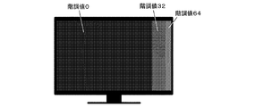
パッチ画像が配置された画像データを生成し、生成した画像データを表示装置300に出力する。具体的には、パッチ表示部205は、輝度カテゴリ毎に、推定輝度値がその輝度カテゴリに属すと判断された全てのパッチ画像が配置された画像データを生成し、生成した画像データを表示装置300に出力する処理を行う。それにより、輝度カテゴリ毎に、推定輝度値がその輝度カテゴリに属すと判断された全てのパッチ画像が、表示装置300の画面に同時に表示される。具体的には、図3に示すように、予め用意された9つのパッチ画像が、3回に分けて画面に表示される。
Then, the
本実施例では、パッチ表示部205の処理の実行中に、撮像装置400による撮像が行われる。具体的には、撮像装置400は、輝度カテゴリ毎に撮像を行い、輝度カテゴリ毎の撮像結果(撮像画像)を校正部206に出力する。
In the present embodiment, imaging by the
次に、校正部206が、撮像装置400が出力した撮像画像からパッチ測定値(パッチ画像の測定値)を取得し、取得したパッチ測定値に基づいてキャリブレーションを実行する。具体的には、輝度カテゴリ毎に、撮像画像に写っている全てのパッチ画像の測定値が取得される。そして、取得された全てのパッチ測定値を用いてキャリブレーションが実行される。
Next, the
輝度の差が大きい複数のパッチ画像(例えば、階調値が255の高輝度パッチ画像と階調値が0の低輝度パッチ画像)を画面に同時に表示すると、高輝度パッチ画像からの光が表示装置300周囲の壁に反射し、反射光が低輝度パッチ画像に照射されてしまう。その結果、低輝度パッチ画像の表示輝度が反射光によって高められ、低輝度パッチ画像の測定値に誤差が生じてしまう。色の差が大きい複数のパッチ画像を画面に表示した場合にも、同様に誤差が生じてしまう。その結果、キャリブレーションの精度が低下してしまう。
When a plurality of patch images having a large difference in luminance (for example, a high-intensity patch image with a gradation value of 255 and a low-intensity patch image with a gradation value of 0) are simultaneously displayed on the screen, light from the high-intensity patch image is displayed. The light is reflected on the wall around the
本実施例によれば、複数のキャリブレーション用画像のそれぞれについて、そのキャリブレーション用画像の特徴量が、特徴量の取り得る範囲を構成する複数の部分範囲のうちのいずれに属すかが判断される。そして、特徴量が属すと判断された部分範囲が互いに異なる複数のキャリブレーション用画像が表示装置に同時に表示させられず、特徴量が属すと判断された部分範囲が互いに等しい複数のキャリブレーション用画像が表示装置に同時に表示させられる。その結果、特徴量が大きく異なる複数のキャリブレーション用画像が表示装置に同時に表示されることを抑制することができるため、上述した誤差を低減することができ、高精度にキャリブレーションを行うことができる。また、キャリブレーション用画像が表示装置に同時に表示されるため、キャリブレーション用画像の表示回数を低減することができ、短時間でキャリブレーションを行うことができる。 According to the present embodiment, for each of the plurality of calibration images, it is determined which of the plurality of partial ranges that constitute the range that the feature amount can take for the feature amount of the calibration image. The A plurality of calibration images having different partial ranges determined to belong to the feature quantity are not simultaneously displayed on the display device, and a plurality of calibration images having the same partial ranges determined to belong to the feature quantity are equal to each other. Are simultaneously displayed on the display device. As a result, it is possible to suppress a plurality of calibration images having greatly different feature amounts from being displayed on the display device at the same time, so that the above-described error can be reduced and calibration can be performed with high accuracy. it can. In addition, since the calibration image is displayed on the display device at the same time, the number of times the calibration image is displayed can be reduced, and the calibration can be performed in a short time.
なお、本実施例では、予め用意された全てのキャリブレーション用画像の測定値を用いてキャリブレーションを実行する例を説明したが、これに限らない。例えば、予め用意された複数のキャリブレーション用画像の一部の測定値を用いずにキャリブレーションが行われてもよい。キャリブレーションに測定値が使用されないキャリブレーション用画像は表示装置に表示されなくてもよい。例えば、1つの部分範囲を特定部分範囲として使用し、特徴量が特定部分範囲以外の部分範囲に属すキャリブレーション用画像を表示装置に表示させなくてもよい。そして、特徴量が特定部分範囲に属す複数のキャリブレーション用画像を表示装置に同時に表示させ、特徴量が特定部分範囲に属す複数のキャリブレーション用画像の測定値に基づいてキャリブレーションが行われてもよい。 In the present embodiment, an example in which calibration is executed using measurement values of all calibration images prepared in advance has been described. However, the present invention is not limited to this. For example, calibration may be performed without using some measurement values of a plurality of calibration images prepared in advance. A calibration image in which measured values are not used for calibration may not be displayed on the display device. For example, one partial range may be used as the specific partial range, and the calibration image whose feature amount belongs to a partial range other than the specific partial range may not be displayed on the display device. A plurality of calibration images whose feature amounts belong to the specific partial range are simultaneously displayed on the display device, and calibration is performed based on the measurement values of the plurality of calibration images whose feature amounts belong to the specific partial range. Also good.
なお、校正装置では以下の処理が行われてもよい。
部分範囲の数を少なくすれば、キャリブレーションをより短時間で行うことができる。しかしながら、部分範囲の数を少なくすると、反射光による誤差が大きい測定値が得られてしまうことがある。例えば、使用環境に依って誤差が大きい測定値が得られてしまうこ
とがある。部分範囲の数を多くすれば、測定値の誤差をより確実に低減することができるが、キャリブレーションの処理時間が増してしまう。
以下の処理によれば、測定値の誤差をより確実に低減し、キャリブレーションを短時間で行うことができる。
Note that the following processing may be performed in the calibration apparatus.
If the number of partial ranges is reduced, calibration can be performed in a shorter time. However, if the number of partial ranges is reduced, a measurement value with a large error due to reflected light may be obtained. For example, a measurement value with a large error may be obtained depending on the use environment. Increasing the number of partial ranges can more reliably reduce measurement error, but increases the calibration processing time.
According to the following processing, it is possible to more reliably reduce the error of the measurement value and perform calibration in a short time.
まず、複数の部分範囲として複数の第1部分範囲を用いて、パッチ画像の特徴量が属す部分範囲を判断する判断処理、パッチ画像を表示装置に表示させる表示処理、及び、パッチ測定値を取得する取得処理が実行される。
複数の第1部分範囲を用いた場合の表示処理では、特徴量が属すと判断された第1部分範囲が互いに等しい複数の第1キャリブレーション用画像と第1階調値の画像とが、表示装置に同時に表示させられる。
また、複数の第1部分範囲を用いた場合の取得処理では、第1階調値の画像の測定値がさらに取得される。第1階調値は特に限定されない。第1階調値は例えば0(黒色に対応する階調値)である。なお、第1階調値の測定値は、パッチ測定値を取得する機能部とは異なる機能部で取得されてもよい。例えば、校正装置200が、第1階調値の測定値を取得する第1取得部を有していてもよい。
First, using a plurality of first partial ranges as a plurality of partial ranges, determination processing for determining a partial range to which the feature amount of the patch image belongs, display processing for displaying the patch image on a display device, and acquiring patch measurement values The acquisition process is executed.
In the display processing when a plurality of first partial ranges are used, a plurality of first calibration images and first gradation value images whose first partial ranges determined to belong to the feature amount are displayed are displayed. It is displayed on the device at the same time.
In addition, in the acquisition process using a plurality of first partial ranges, the measurement value of the image having the first gradation value is further acquired. The first gradation value is not particularly limited. The first gradation value is, for example, 0 (gradation value corresponding to black). Note that the measurement value of the first gradation value may be acquired by a functional unit different from the functional unit that acquires the patch measurement value. For example, the
次に、複数の第1部分範囲の間の第1階調値の測定値のばらつき度合いが算出される。なお、ばらつき度合いを算出する処理は、どの機能部で行われてもよい。校正装置が、ばらつき度合いを算出する算出部を有していてもよい。
そして、算出されたばらつき度合いが閾値以上か否かが判断される。なお、ばらつき度合いが閾値以上か否かを判断する処理は、校正装置が、ばらつき度合いが閾値以上か否かを判断する判断部を有していてもよい。また、ばらつき度合いと比較する閾値は、メーカーによって予め定められた固定値であってもよいし、ユーザが変更可能な値であってもよい。
Next, the degree of variation in the measured value of the first gradation value between the plurality of first partial ranges is calculated. Note that the processing for calculating the degree of variation may be performed by any functional unit. The calibration apparatus may include a calculation unit that calculates the degree of variation.
Then, it is determined whether or not the calculated degree of variation is greater than or equal to a threshold value. In the process of determining whether or not the degree of variation is equal to or greater than a threshold, the calibration apparatus may include a determination unit that determines whether or not the degree of variation is equal to or greater than the threshold. Further, the threshold value to be compared with the degree of variation may be a fixed value determined in advance by the manufacturer, or may be a value that can be changed by the user.
算出されたばらつき度合いが閾値未満の場合には、複数の第1部分範囲を用いた場合の取得処理で取得されたパッチ測定値を用いてキャリブレーションが実行される。
算出されたばらつき度合いが閾値以上の場合には、複数の部分範囲として、特徴量の取り得る範囲を構成し、且つ、複数の第1部分範囲よりも数が多い複数の第2部分範囲を用いて、判断処理、制御処理、及び、取得処理が再度実行される。そして、複数の第2部分範囲を用いた場合の取得処理で取得されたパッチ測定値を用いてキャリブレーションが実行される。
When the calculated degree of variation is less than the threshold value, calibration is executed using the patch measurement values acquired in the acquisition process when a plurality of first partial ranges are used.
When the calculated degree of variation is equal to or greater than a threshold, a plurality of second partial ranges that constitute a range that can be taken as a feature amount and that have a larger number than the plurality of first partial ranges are used as the plurality of partial ranges. Thus, the determination process, the control process, and the acquisition process are executed again. Then, calibration is executed using the patch measurement values acquired in the acquisition process in the case of using a plurality of second partial ranges.
第1階調値の測定値のばらつき度合いが大きい場合には、反射光による誤差が大きい測定値が得られている可能性が高い。上記処理によれば、そのような場合に、特徴量の取り得る範囲をより細かく分割して得られる第2部分範囲が使用されるため、反射光による誤差をより確実に低減することができる。また、第1階調値の測定値のばらつき度合いが小さい場合には、第1部分範囲が使用されるため、常に第2部分範囲を使用する場合に比べて、キャリブレーションの処理時間を短縮することができる。 When the variation degree of the measurement value of the first gradation value is large, there is a high possibility that a measurement value with a large error due to reflected light is obtained. According to the above processing, in such a case, since the second partial range obtained by finely dividing the range that can be taken by the feature amount is used, errors due to reflected light can be more reliably reduced. In addition, since the first partial range is used when the degree of variation of the measurement value of the first gradation value is small, the calibration processing time is shortened compared to the case where the second partial range is always used. be able to.
なお、複数の第1部分範囲を用いた場合の制御処理では、複数の第1部分範囲の間で第1階調値の画像の表示位置が互いに等しくなるように、第1階調値の画像が表示装置に表示させられることが好ましい。それにより、上記ばらつき度合いとして、反射光による誤差をより正確に表す値を得ることができる。 Note that in the control processing when a plurality of first partial ranges are used, the first gradation value image is set so that the display positions of the first gradation value images are equal to each other among the plurality of first partial ranges. Is preferably displayed on the display device. Accordingly, a value that more accurately represents the error due to the reflected light can be obtained as the degree of variation.
なお、複数の第1部分範囲が使用される場合と複数の第2部分範囲が使用される場合とで使用するキャリブレーション用画像が異なっていてもよい。例えば、複数の第1部分範囲が使用される場合に、複数の第1キャリブレーション用画像が使用され、複数の第2部分範囲が使用される場合に、複数の第1キャリブレーション用画像よりも数が多い複数の
第2キャリブレーション用画像が使用されてもよい。複数の第2部分範囲を使用する場合には、同時に表示されるキャリブレーション用画像の数が減るため、複数の第2部分範囲を使用する場合よりも多くのキャリブレーション用画像を同時に表示することができる。このような構成によれば、複数の第2部分範囲を使用する場合のキャリブレーションの精度をより高めることができる。複数の第2キャリブレーション用画像は、複数の第1キャリブレーション用画像を含んでいてもよいし、含まなくてもよい。
Note that the calibration image to be used may be different when a plurality of first partial ranges are used and when a plurality of second partial ranges are used. For example, when a plurality of first partial ranges are used, a plurality of first calibration images are used, and when a plurality of second partial ranges are used, than a plurality of first calibration images. A plurality of second calibration images may be used. When using a plurality of second partial ranges, the number of calibration images displayed simultaneously is reduced, so that more calibration images can be displayed simultaneously than when using a plurality of second partial ranges. Can do. According to such a configuration, it is possible to further improve the accuracy of calibration when using a plurality of second partial ranges. The plurality of second calibration images may or may not include a plurality of first calibration images.
<実施例2>
以下、本発明の実施例2に係る校正装置及び校正方法について、図面を用いて説明する。
実施例1では、予め用意された複数のキャリブレーション用画像を複数回に分けて画面に表示する処理を常に行う例を説明した。
しかし、使用環境に依っては、反射光の影響が小さく、予め用意された全てのキャリブレーション用画像を同時に表示しても誤差が大きいキャリブレーション用測定値が得られないことがある。
本実施例では、反射光の影響が小さい場合に、予め用意された全てのキャリブレーション用画像を同時に表示する例を説明する。
このような構成によれば、キャリブレーション用画像の表示回数をより低減できるため、キャリブレーションの処理時間をより短縮することができる。
<Example 2>
Hereinafter, a calibration device and a calibration method according to Embodiment 2 of the present invention will be described with reference to the drawings.
In the first embodiment, the example in which the process of displaying the plurality of calibration images prepared in advance on the screen in a plurality of times has been described.
However, depending on the use environment, the measurement value for calibration with a large error may not be obtained even if all the calibration images prepared in advance are displayed at the same time because the influence of the reflected light is small.
In the present embodiment, an example will be described in which all calibration images prepared in advance are displayed simultaneously when the influence of reflected light is small.
According to such a configuration, the number of times the calibration image is displayed can be further reduced, so that the calibration processing time can be further shortened.
図4は、本実施例に係る校正システム500の一例を示すブロック図である。図4において、実施例1(図1)と同じ機能部及び装置には同じ符号を付し、その説明は省略する。
図4に示すように、校正システム500は、校正装置600、表示装置300、撮像装置400、等を有する。
校正装置600は、目標値取得部201、パッチ階調値記憶部202、パッチ特徴取得部203、パッチ判断部604、パッチ表示部605、校正部206、影響判断部607等を有する。
FIG. 4 is a block diagram illustrating an example of a
As illustrated in FIG. 4, the
The
パッチ表示部605は、キャリブレーション用画像の表示を開始する前に、第2階調値の画像を表示装置300に表示させる第1処理、及び、第2階調値の画像と第3階調値の画像とを表示装置に同時に表示させる第2処理、を順に行う。キャリブレーション用画像の表示方法は、実施例1に係るパッチ表示部205と同じである。
The
影響判断部607は、第2階調値の画像の測定値を取得し、取得した測定値に基づいて反射光の影響の有無を判断する。具体的には、影響判断部607は、第2処理で表示された第2階調値の測定値に対する第1処理で表示された第2階調値の測定値のずれ度合いが閾値以下であるか否かを判断する。影響判断部607は、上記ずれ度合いが閾値より大きい場合に、反射光の影響があると判断し、上記ずれ度合いが閾値以下である場合には、反射光の影響が無いと判断する。影響判断部607は、反射光の影響の有無の判断結果をパッチ判断部604に出力する。
なお、第2階調値の測定値は、影響判断部607とは異なる機能部で取得されてもよい。例えば、校正装置600が、第2階調値の測定値を取得する第2取得部を有していてもよい。
なお、ずれ度合いと比較する閾値は、メーカーによって予め定められた固定値であってもよいし、ユーザが変更可能な値であってもよい。
The
Note that the measurement value of the second gradation value may be acquired by a functional unit different from the
The threshold value to be compared with the degree of deviation may be a fixed value determined in advance by the manufacturer, or may be a value that can be changed by the user.
パッチ判断部604は、反射光の影響の有無の判断結果に基づいて分類情報を生成し、生成した分類情報をパッチ表示部605に出力する。具体的には、反射光の影響があると判断された場合には、実施例1と同様の方法で分類情報が生成される。反射光の影響が無
いと判断された場合には、予め用意された全てのグラフィック画像を同時に表示させるための分類情報(予め用意された全てのグラフィック画像を1つの輝度カテゴリに対応付けた分類情報)が生成される。
そのため、反射光の影響があると判断された場合には、パッチ表示部605において、実施例1と同様に、予め用意された複数のキャリブレーション用画像を複数回に分けて表示装置300に表示させる処理が行われる。そして、反射光の影響が無いと判断された場合には、パッチ表示部605において、予め用意された全てのキャリブレーション用画像を表示装置300に同時に表示させる処理が行われる。
The
For this reason, when it is determined that there is an influence of reflected light, the
以下、校正装置600の動作について具体的に説明する。
なお、実施例1と同様の動作については、説明を省略する。
なお、本実施例では、実施例1と同じ9つのパッチ画像がキャリブレーションに使用されるものとする。
Hereinafter, the operation of the
Note that description of operations similar to those of the first embodiment is omitted.
In the present embodiment, the same nine patch images as in the first embodiment are used for calibration.
まず、パッチ表示部605は、キャリブレーション用画像の表示を開始する前に、第2階調値の画像を表示装置300に表示させる第1処理、及び、第2階調値の画像と第3階調値の画像とを表示装置に同時に表示させる第2処理、を順に行う。
なお、影響判断部607が、第1処理で表示する画像と第2処理で表示する画像とを生成し、生成したそれらの画像をパッチ表示部605に出力してもよい。そして、パッチ表示部605が、影響判断部607から出力された画像を表示装置300に表示させてもよい。
First, before starting the display of the calibration image, the
Note that the
本実施例では、第2階調値として黒色に対応する階調値0が使用され、第3階調値として白色に対応する階調値255が使用される。具体的には、第1処理では図5(A)に示す画像が表示され、第2処理では図5(B)に示す画像が表示される。
なお、第2階調値と第3階調値は上記値に限らない。第2階調値と第3階調値はどのような値であってもよい。但し、第3階調値は、反射光の影響がある場合に第2階調値の画像の表示輝度により大きな変化をもたらす値であることが好ましい。そのため、第3階調値は、第2階調値よりも大きいことが好ましい。換言すれば、第3階調値の画像は、第2階調値の画像よりも明るいことが好ましい。第2階調値の画像よりも明るい画像を第3階調値の画像として使用することにより、反射光の影響の有無を高精度に判断することができる。また、第3階調値の画像の明るさから第2階調値の画像の明るさを減算した値が大きいほど精度良く反射光の影響の有無を判断できる。そのため、第2階調値として黒色に対応する階調値を使用し、第3階調値として白色に対応する階調値を使用すれば、非常に高い精度で反射光の影響の有無を判断することができる。
また、第1処理と第2処理で表示される画像は図5(A),5(B)に示す画像に限らない。例えば、図5(B)では、第3画素値の画像を囲むように第2画素値の画像が配置されているが、第3画素値の画像と第2画素値の画像が左右方向に並べて配置されていてもよい。
In the present embodiment, a gradation value 0 corresponding to black is used as the second gradation value, and a
The second gradation value and the third gradation value are not limited to the above values. The second gradation value and the third gradation value may be any value. However, the third gradation value is preferably a value that causes a large change in the display brightness of the image of the second gradation value when there is an influence of reflected light. Therefore, it is preferable that the third gradation value is larger than the second gradation value. In other words, the image of the third gradation value is preferably brighter than the image of the second gradation value. By using an image brighter than the second gradation value image as the third gradation value image, the presence or absence of the influence of the reflected light can be determined with high accuracy. Further, the larger the value obtained by subtracting the brightness of the second gradation value image from the brightness of the third gradation value image, the more accurately the presence or absence of the influence of the reflected light can be determined. Therefore, if the gradation value corresponding to black is used as the second gradation value and the gradation value corresponding to white is used as the third gradation value, the presence or absence of the influence of reflected light can be determined with very high accuracy. can do.
Further, the images displayed in the first process and the second process are not limited to the images shown in FIGS. 5 (A) and 5 (B). For example, in FIG. 5B, the second pixel value image is arranged so as to surround the third pixel value image. However, the third pixel value image and the second pixel value image are arranged in the horizontal direction. It may be arranged.
本実施例では、第1処理及び第2処理の実行中に、撮像装置400による撮像が行われる。そして、撮像装置400は、第1処理の実行中に得た撮像画像(第1撮像画像)と、第2処理の実行中に得た撮像画像(第2撮像画像)と、を影響判断部607に出力する。
In the present embodiment, imaging is performed by the
次に、影響判断部607が、撮像装置400が出力した第1撮像画像から第1測定値を取得し、撮像装置400が出力した第2撮像画像から第2測定値を取得する。第1測定値は、第1処理で表示された第2階調値の測定値であり、第2測定値は、第2処理で表示された第2階調値の測定値である。
Next, the
そして、影響判断部607は、取得した第1測定値と第2測定値に基づいて、反射光の
影響の有無を判断し、判断結果をパッチ判断部604に出力する。具体的には、影響判断部607は、取得した第1測定値と第2測定値が以下の式2を満たすか否かを判断する。式2において、“Lu_1”は第1測定値であり、“Lu_2”は第2測定値であり、“L_Th”は閾値である。第1測定値と第2測定値が式2を満たす場合には、反射光の影響
が無いと判断され、第1測定値と第2測定値が式2を満たさない場合には、反射光の影響があると判断される。つまり、第1測定値Lu_1と第2測定値Lu_2が同等である場合には反射光の影響が無いと判断される。そして、影響判断部607は、反射光の影響が無いと判断した場合にフラグF1をパッチ判断部604に出力し、反射光の影響があると判断した場合にフラグF2をパッチ判断部604に出力する。
|(Lu_1―Lu_2)÷Lu_2|×100≦Th ・・・(式2)
Then, the
| (Lu_1−Lu_2) ÷ Lu_2 | × 100 ≦ Th (Expression 2)
次に、パッチ判断部604が、影響判断部607から出力されたフラグに基づいて分類情報を生成し、生成した分類情報をパッチ表示部605に出力する。
具体的には、パッチ判断部604は、フラグF1を受信した場合に、9つ全てのパッチ画像を同時に表示させるための分類情報を生成する。
また、パッチ判断部604は、フラグF2を受信した場合に、実施例1と同様に、9つパッチ画像を3回に分けて表示させるための分類情報を生成する。
なお、分類情報を生成する処理の前に、実施例1と同様に、目標値を取得する処理、及び、特徴量を取得する処理が行われる。
Next, the
Specifically, the
Further, when receiving the flag F2, the
In addition, before the process which produces | generates classification information, the process which acquires a target value, and the process which acquires a feature-value are performed similarly to Example 1. FIG.
そして、パッチ表示部605が、パッチ判断部604からの分類情報に基づいて複数のパッチ画像が配置された画像データを生成し、生成した画像データを表示装置300に出力する。その結果、影響判断部607からフラグF1が出力された場合には、図6に示すように、9つの全てのパッチ画像が画面に同時に表示される。影響判断部607からフラグF2が出力された場合には、実施例1(図3)と同様に、9つのパッチ画像が3回に分けて表示される。
パッチ画像が表示された後、実施例1と同様に、画面を撮像する処理、パッチ測定値を取得する処理、及び、キャリブレーションの実行が行われる。
Then, the
After the patch image is displayed, similarly to the first embodiment, a process of capturing a screen, a process of acquiring a patch measurement value, and execution of calibration are performed.
以上述べたように、本実施例によれば、反射光の影響の有無が判断され、反射光の影響が無いと判断された場合に、予め用意された全てのキャリブレーション用画像が同時に表示される。それにより、キャリブレーション用画像の表示回数をより低減できるため、キャリブレーションの処理時間をより短縮することができる。 As described above, according to the present embodiment, when the presence or absence of the influence of the reflected light is determined and it is determined that there is no influence of the reflected light, all the calibration images prepared in advance are displayed simultaneously. The As a result, the number of times the calibration image is displayed can be further reduced, and the calibration processing time can be further shortened.
<実施例3>
以下、本発明の実施例3に係る校正装置及び校正方法について、図面を用いて説明する。
本実施例では、実施例1,2よりも高精度なキャリブレーションを行うことのできる例を説明する。
<Example 3>
Hereinafter, a calibration device and a calibration method according to Example 3 of the present invention will be described with reference to the drawings.
In the present embodiment, an example in which calibration can be performed with higher accuracy than in the first and second embodiments will be described.
図7は、本実施例に係る校正システム700の一例を示すブロック図である。図7において、実施例1,2(図1,4)と同じ機能部及び装置には同じ符号を付し、その説明は省略する。
図7に示すように、校正システム700は、校正装置800、表示装置300、撮像装置400、等を有する。
校正装置800は、目標値取得部201、パッチ階調値記憶部202、パッチ特徴取得部203、パッチ判断部604、パッチ表示部805、校正部206、影響判断部607、パッチ面積決定部808、等を有する。
なお、図7は、実施例2(図4)の校正装置にパッチ面積決定部808を追加した例を示しているが、実施例1(図1)の校正装置にパッチ面積決定部808を追加してもよい。
FIG. 7 is a block diagram illustrating an example of a
As illustrated in FIG. 7, the
The
7 shows an example in which the patch
パッチ面積決定部808は、パッチ判断部604から分類情報を取得し、パッチ特徴取得部203からパッチ画像の推定輝度値を取得する。そして、パッチ面積決定部808は、取得した分類情報と推定輝度値に基づいて各パッチ画像の面積を決定し、決定した面積を表す面積情報をパッチ表示部805に出力する。具体的には、パッチ面積決定部808は、同時に表示させる複数のパッチ画像の間で、パッチ画像の輝度にパッチ画像の面積を乗算した値が互いに等しくなるように、各パッチ画像の面積(表示面積)を決定する。以後、パッチ画像の輝度にパッチ画像の面積を乗算した値を“面輝度”と記載する。
また、パッチ面積決定部808は、取得した分類情報もパッチ表示部805に出力する。
なお、パッチ画像の面積を決定する際に、推定輝度値ではなく、パッチ画像の階調値やその代表値が使用されてもよい。例えば、パッチ画像のRGB値から算出したY値(YCbCr値のY値)やその代表値が使用されてもよい。
The patch
The patch
Note that when determining the area of the patch image, the tone value of the patch image or its representative value may be used instead of the estimated luminance value. For example, a Y value (Y value of YCbCr value) calculated from the RGB values of the patch image or a representative value thereof may be used.
本実施例では、パッチ面積決定部808は、部分範囲毎に、特徴量がその部分範囲に属すと判断された各パッチ画像の面積を、以下の式3を用いて算出する。式3において、“S(n)”は階調値nのパッチ画像の面積Sであり、“L”は面輝度であり、“Pre_Lu(n)”は階調値nのパッチ画像の推定輝度値Pre_Luである。面輝度Lは、メーカーによって予め定められた固定値であってもよいし、ユーザが変更可能な値であってもよい。また、校正装置800が、表示装置300の設置環境、使用目的、等に応じて面輝度Lを決定してもよい。本実施例では、面輝度Lが1.0であるものとする。
S(n)=L÷Pre_Lu ・・・(式3)
In the present embodiment, the patch
S (n) = L ÷ Pre_Lu (Expression 3)
そして、パッチ面積決定部808は、以下の式4を用いて、面積Sから面積比率S_ratioを算出する。その後、パッチ面積決定部808は、分類情報と各パッチ画像の面積比率S_ratioとをパッチ表示部805に出力する。面積比率S_ratio(n)は、階調値nのパッチ画像の面積比率S_ratioであり、特徴量が属すと判断された部分範囲が互いに等しい全てのパッチ画像の面積Sの総和に対するパッチ画像の面積S(n)の割合である。式4を用いた場合、面積比率S_ratioとして、最大値が100になるように規格化された値が得られる。
なお、面積と推定輝度値との対応関係を表すテーブルを用いてパッチ画像の面積が決定されてもよいし、面積比率と推定輝度値との対応関係を表すテーブルを用いてパッチ画像の面積が決定されてもよい。
Then, the patch
Note that the area of the patch image may be determined using a table representing the correspondence between the area and the estimated luminance value, or the area of the patch image may be determined using the table representing the correspondence between the area ratio and the estimated luminance value. It may be determined.
実施例1で示した表3に示す分類情報と推定輝度値が取得された場合、部分範囲である輝度カテゴリ1については、以下の表4に示す面積Sと面積比率S_ratioが得られる。
When the classification information and the estimated luminance value shown in Table 3 shown in Example 1 are acquired, the area S and the area ratio S_ratio shown in Table 4 below are obtained for the luminance category 1 that is a partial range.
パッチ表示部805は、パッチ画像の輝度が高いほど小さい面積でパッチ画像が表示されるように、属すと判断された部分範囲が互いに等しい複数のパッチ画像を表示装置300に同時に表示させる。具体的には、パッチ画像がパッチ面積決定部808で決定された面積で表示されるように、属すと判断された部分範囲が互いに等しい複数のパッチ画像を表示装置300に同時に表示させる。本実施例では、パッチ面積決定部808で決定された面積比率S_ratioで複数のパッチ画像(属すと判断された部分範囲が互いに等しい複数のパッチ画像)を並べた画像が画面に表示させられる。その結果、図8に示すように、属すと判断された部分範囲が互いに等しい複数のパッチ画像が、パッチ画像の輝度が高いほど小さい面積で表示される。
The
キャリブレーション用画像の面積が小さいほど、そのキャリブレーション用画像が他のキャリブレーション用画像の表示輝度に与える影響は小さい。また、キャリブレーション用画像からの距離が遠いほど、そのキャリブレーション用画像から受ける影響は小さい。
本実施例によれば、属すと判断された部分範囲が互いに等しい複数のキャリブレーション用画像が、キャリブレーション用画像の輝度が高いほど小さい面積で表示される。即ち、他のキャリブレーション用画像の表示輝度に与える影響が大きい高輝度なキャリブレーション用画像が、低輝度なキャリブレーション用画像よりも小さい面積で表示される。
それにより、高輝度なキャリブレーション用画像が他のキャリブレーション用画像の表示輝度に与える影響を低減することができ、キャリブレーションの精度をより高めることができる。
また、低輝度なキャリブレーション用画像の測定値を取得する取得位置として、高輝度なキャリブレーション用画像からより遠い位置を設定することが可能となる。そのため、低輝度なキャリブレーション用画像の測定値として、より誤差の小さい測定値を得ることができ、キャリブレーションの精度をより高めることができる。
The smaller the area of the calibration image, the smaller the influence of the calibration image on the display brightness of the other calibration images. Further, the farther the distance from the calibration image is, the smaller the influence from the calibration image is.
According to this embodiment, a plurality of calibration images having the same partial range determined to belong to each other are displayed with a smaller area as the luminance of the calibration image is higher. That is, a high-brightness calibration image that has a large effect on the display brightness of other calibration images is displayed in a smaller area than a low-brightness calibration image.
As a result, the influence of the high-brightness calibration image on the display brightness of other calibration images can be reduced, and the calibration accuracy can be further increased.
Further, it is possible to set a position farther from the calibration image with high luminance as the acquisition position for acquiring the measurement value of the calibration image with low luminance. Therefore, a measurement value with a smaller error can be obtained as the measurement value of the calibration image with low brightness, and the calibration accuracy can be further improved.
なお、実施例1〜3において得られる効果は、上述したものだけではない。
一般に、撮像装置は内蔵されている撮像素子の飽和特性、ノイズレベル、等の種々の特性の影響から、被写体の輝度毎に最適な露光時間が異なる。
実施例1〜3によれば、部分範囲毎に、特徴量がその部分範囲に属すと判断された複数のキャリブレーション用画像が表示装置に同時に表示される。それにより、表示輝度が大きく異なる複数のキャリブレーション用画像が表示装置に同時に表示されることを抑制することができ、表示輝度が同程度の複数のキャリブレーション用画像を表示装置に同時に表示することができる。そして、部分範囲毎に適切な露光時間を選択することができ、撮像装置のダイナミックレンジを有効活用することができる。
In addition, the effect acquired in Examples 1-3 is not only what was mentioned above.
In general, an imaging apparatus has an optimum exposure time for each luminance of an object due to the influence of various characteristics such as saturation characteristics and noise level of a built-in imaging device.
According to the first to third embodiments, for each partial range, a plurality of calibration images for which the feature amount is determined to belong to the partial range are simultaneously displayed on the display device. Accordingly, it is possible to suppress a plurality of calibration images having greatly different display luminances from being displayed on the display device at the same time, and to simultaneously display a plurality of calibration images having substantially the same display luminance on the display device. Can do. An appropriate exposure time can be selected for each partial range, and the dynamic range of the imaging apparatus can be effectively utilized.
<その他の実施例>
記憶装置に記録されたプログラムを読み込み実行することで前述した実施例の機能を実現するシステムや装置のコンピュータ(又はCPU、MPU等のデバイス)によっても、本発明を実施することができる。また、例えば、記憶装置に記録されたプログラムを読み
込み実行することで前述した実施例の機能を実現するシステムや装置のコンピュータによって実行されるステップからなる方法によっても、本発明を実施することができる。この目的のために、上記プログラムは、例えば、ネットワークを通じて、又は、上記記憶装置となり得る様々なタイプの記録媒体(つまり、非一時的にデータを保持するコンピュータ読取可能な記録媒体)から、上記コンピュータに提供される。したがって、上記コンピュータ(CPU、MPU等のデバイスを含む)、上記方法、上記プログラム(プログラムコード、プログラムプロダクトを含む)、上記プログラムを非一時的に保持するコンピュータ読取可能な記録媒体は、いずれも本発明の範疇に含まれる。
<Other examples>
The present invention can also be implemented by a system (or a device such as a CPU or MPU) of a system or apparatus that implements the functions of the above-described embodiments by reading and executing a program recorded in a storage device. The present invention can also be implemented by a method comprising steps executed by a computer of a system or apparatus that implements the functions of the above-described embodiments by reading and executing a program recorded in a storage device, for example. . For this purpose, the program is stored in the computer from, for example, various types of recording media that can serve as the storage device (ie, computer-readable recording media that holds data non-temporarily). Provided to. Therefore, the computer (including devices such as CPU and MPU), the method, the program (including program code and program product), and the computer-readable recording medium that holds the program non-temporarily are all present. It is included in the category of the invention.
200,600,800:校正装置 204,604:パッチ判断部 205,605,805:パッチ表示部 206:校正部
200, 600, 800:
Claims (25)
複数のキャリブレーション用画像のそれぞれについて、そのキャリブレーション用画像の特徴量が、特徴量の取り得る範囲を構成する複数の部分範囲のうちのいずれに属すかを判断する判断手段と、
特徴量が属すと判断された部分範囲が互いに等しい2つ以上のキャリブレーション用画像を前記表示装置に同時に表示させる表示手段と、
前記キャリブレーション用画像の表示輝度と表示色の少なくとも一方を表す測定値であるキャリブレーション用測定値を取得する取得手段と、
前記取得手段で取得された前記キャリブレーション用測定値に基づいて、前記表示装置のキャリブレーションを実行する校正手段と、
を有することを特徴とする校正装置。 A calibration device for calibrating a display device,
For each of the plurality of calibration images, a determination unit that determines which of a plurality of partial ranges that constitute a range that the feature amount can be taken by the feature amount of the calibration image;
Display means for simultaneously displaying on the display device two or more calibration images having the same partial ranges determined to belong to the feature amount;
Obtaining means for obtaining a calibration measurement value, which is a measurement value representing at least one of display luminance and display color of the calibration image;
Calibration means for calibrating the display device based on the calibration measurement values acquired by the acquisition means;
A calibration apparatus comprising:
ことを特徴とする請求項1に記載の校正装置。 2. The calibration according to claim 1, wherein the display unit displays, on the display device, two or more calibration images in which a feature amount is determined to belong to the partial range for each partial range. apparatus.
前記複数の第1部分範囲を用いた場合の表示処理では、特徴量が属すと判断された第1部分範囲が互いに等しい2つ以上の第1キャリブレーション用画像と第1階調値の画像とが、前記表示装置に同時に表示させられ、
前記校正装置は、前記第1階調値の画像の測定値を取得する第1取得手段をさらに有し、
前記複数の第1部分範囲の間の前記第1階調値の測定値のばらつき度合いが閾値未満の場合には、前記校正手段は、前記複数の第1部分範囲を用いた場合の取得処理で取得されたキャリブレーション用測定値を用いて前記キャリブレーションを実行し、
前記複数の第1部分範囲の間の前記第1階調値の測定値のばらつき度合いが前記閾値以上の場合には、前記複数の部分範囲として、特徴量の取り得る範囲を構成し、且つ、複数の第1部分範囲よりも数が多い複数の第2部分範囲を用いて、前記判断処理、前記制御処理、及び、前記取得処理が再度実行され、前記校正手段は、前記複数の第2部分範囲を用いた場合の取得処理で取得されたキャリブレーション用測定値を用いて前記キャリブレーションを実行する
ことを特徴とする請求項2に記載の校正装置。 Judgment processing for determining a partial range to which a feature amount of a calibration image belongs using a plurality of first partial ranges constituting a range that a feature amount can take as the plurality of partial ranges, and a calibration image for the display device Display processing to be displayed on the display and acquisition processing for acquiring the measurement value for calibration are executed,
In the display process when the plurality of first partial ranges are used, two or more first calibration images and first gradation value images having the same first partial range determined to belong to the feature amount, Are simultaneously displayed on the display device,
The calibration apparatus further includes first acquisition means for acquiring a measurement value of the image of the first gradation value,
When the degree of variation in the measured value of the first gradation value between the plurality of first partial ranges is less than a threshold value, the calibration unit performs an acquisition process using the plurality of first partial ranges. Execute the calibration using the acquired measurement value for calibration,
When the degree of variation in the measured value of the first gradation value between the plurality of first partial ranges is equal to or greater than the threshold, a range that can be taken as a feature amount is configured as the plurality of partial ranges, and The determination process, the control process, and the acquisition process are performed again using a plurality of second partial ranges that are larger in number than the plurality of first partial ranges, and the calibration means includes the plurality of second parts. The calibration apparatus according to claim 2, wherein the calibration is performed using a calibration measurement value acquired in an acquisition process when a range is used.
ことを特徴とする請求項3に記載の校正装置。 In the control process using the plurality of first partial ranges, the first gradation value is set so that the display positions of the images of the first gradation value are equal to each other between the plurality of first partial ranges. The calibration apparatus according to claim 3, wherein the image is displayed on the display device.
前記複数の第2部分範囲が使用される場合には、前記複数のキャリブレーション用画像として、前記複数の第1キャリブレーション用画像よりも数が多い複数の第2キャリブレーション用画像が使用される
ことを特徴とする請求項3または4に記載の校正装置。 When the plurality of first partial ranges are used, a plurality of first calibration images are used as the plurality of calibration images,
When the plurality of second partial ranges are used, a plurality of second calibration images having a larger number than the plurality of first calibration images are used as the plurality of calibration images. 5. The calibration apparatus according to claim 3 or 4, wherein
前記校正装置は、前記キャリブレーション用画像毎に、そのキャリブレーション用画像の階調値と前記表示装置の表示特性とに基づいて、当該キャリブレーション用画像の表示輝度と表示色の少なくとも一方を推定する推定手段をさらに有し、
前記判断手段は、前記推定手段の推定値が前記複数の部分範囲のうちのいずれに属すかを判断する
ことを特徴とする請求項1〜5のいずれか1項に記載の校正装置。 The feature amount is display luminance, display color, or a combination of display luminance and display color.
For each calibration image, the calibration device estimates at least one of display luminance and display color of the calibration image based on the gradation value of the calibration image and the display characteristics of the display device. And an estimation means for
The calibration device according to claim 1, wherein the determination unit determines which of the plurality of partial ranges the estimated value of the estimation unit belongs to.
ことを特徴とする請求項6に記載の校正装置。 The estimation means estimates at least one of display luminance and display color of the calibration image based on a gradation value of the calibration image and a target value of display characteristics of the display device. The calibration device according to claim 6.
前記校正装置は、前記第2階調値の画像の測定値を取得する第2取得手段をさらに有し、
前記第2処理で表示された第2階調値の測定値に対する前記第1処理で表示された第2階調値の測定値のずれ度合いが閾値以下である場合に、前記表示手段は、全てのキャリブレーション用画像を前記表示装置に同時に表示させる
ことを特徴とする請求項1〜7のいずれか1項に記載の校正装置。 The display means displays the second gradation value image on the display device, and simultaneously displays the second gradation value image and the third gradation value image on the display device. The second process is performed in order,
The calibration apparatus further includes second acquisition means for acquiring a measurement value of the image of the second gradation value,
When the degree of deviation of the measured value of the second gradation value displayed in the first process with respect to the measured value of the second gradation value displayed in the second process is less than or equal to a threshold value, the display means are all The calibration device according to claim 1, wherein the calibration image is simultaneously displayed on the display device.
ことを特徴とする請求項8に記載の校正装置。 The calibration apparatus according to claim 8, wherein the image of the third gradation value is brighter than the image of the second gradation value.
ことを特徴とする請求項8または9に記載の校正装置。 The calibration apparatus according to claim 8 or 9, wherein the second gradation value is a gradation value corresponding to black, and the third gradation value is a gradation value corresponding to white.
ことを特徴とする請求項1〜10のいずれか1項に記載の校正装置。 The display means displays the two or more calibration images on the display device at the same time so that the calibration image is displayed in a smaller area as the luminance of the calibration image is higher. The calibration device according to any one of claims 1 to 10.
前記表示手段は、キャリブレーション用画像が前記決定手段で決定された面積で表示されるように、前記2つ以上のキャリブレーション用画像を前記表示装置に同時に表示させる
ことを特徴とする請求項11に記載の校正装置。 The area of each of the two or more calibration images is such that a value obtained by multiplying the luminance of the calibration image by the area of the calibration image is equal between the two or more calibration images. Further has a determination means for determining
12. The display unit displays the two or more calibration images simultaneously on the display device so that the calibration images are displayed in the area determined by the determination unit. The calibration device described in 1.
複数のキャリブレーション用画像のそれぞれについて、そのキャリブレーション用画像の特徴量が、特徴量の取り得る範囲を構成する複数の部分範囲のうちのいずれに属すかを判断する判断ステップと、
特徴量が属すと判断された部分範囲が互いに等しい2つ以上のキャリブレーション用画像を前記表示装置に同時に表示させる表示ステップと、
前記キャリブレーション用画像の表示輝度と表示色の少なくとも一方を表す測定値であ
るキャリブレーション用測定値を取得する取得ステップと、
前記取得ステップで取得された前記キャリブレーション用測定値に基づいて、前記表示装置のキャリブレーションを実行する校正ステップと、
を有することを特徴とする校正方法。 A display device calibration method comprising:
A determination step of determining, for each of the plurality of calibration images, whether the feature amount of the calibration image belongs to one of a plurality of partial ranges constituting a range that the feature amount can take;
A display step of simultaneously displaying on the display device two or more calibration images having the same partial range determined to belong to the feature amount;
An acquisition step of acquiring a calibration measurement value that is a measurement value representing at least one of display luminance and display color of the calibration image;
A calibration step of performing calibration of the display device based on the calibration measurement value acquired in the acquisition step;
A calibration method characterized by comprising:
ことを特徴とする請求項13に記載の校正方法。 14. The calibration according to claim 13, wherein, in the display step, for each partial range, two or more calibration images for which a feature amount is determined to belong to the partial range are displayed on the display device. Method.
前記複数の第1部分範囲を用いた場合の表示処理では、特徴量が属すと判断された第1部分範囲が互いに等しい2つ以上の第1キャリブレーション用画像と第1階調値の画像とが、前記表示装置に同時に表示させられ、
前記校正方法は、前記第1階調値の画像の測定値を取得する第1取得ステップをさらに有し、
前記複数の第1部分範囲の間の前記第1階調値の測定値のばらつき度合いが閾値未満の場合には、前記校正ステップでは、前記複数の第1部分範囲を用いた場合の取得処理で取得されたキャリブレーション用測定値を用いて前記キャリブレーションを実行し、
前記複数の第1部分範囲の間の前記第1階調値の測定値のばらつき度合いが前記閾値以上の場合には、前記複数の部分範囲として、特徴量の取り得る範囲を構成し、且つ、複数の第1部分範囲よりも数が多い複数の第2部分範囲を用いて、前記判断処理、前記制御処理、及び、前記取得処理が再度実行され、前記校正ステップでは、前記複数の第2部分範囲を用いた場合の取得処理で取得されたキャリブレーション用測定値を用いて前記キャリブレーションを実行する
ことを特徴とする請求項14に記載の校正方法。 Judgment processing for determining a partial range to which a feature amount of a calibration image belongs using a plurality of first partial ranges constituting a range that a feature amount can take as the plurality of partial ranges, and a calibration image for the display device Display processing to be displayed on the display and acquisition processing for acquiring the measurement value for calibration are executed,
In the display process when the plurality of first partial ranges are used, two or more first calibration images and first gradation value images having the same first partial range determined to belong to the feature amount, Are simultaneously displayed on the display device,
The calibration method further includes a first acquisition step of acquiring a measurement value of the image of the first gradation value,
When the variation degree of the measurement value of the first gradation value between the plurality of first partial ranges is less than a threshold value, the calibration step is an acquisition process when the plurality of first partial ranges are used. Execute the calibration using the acquired measurement value for calibration,
When the degree of variation in the measured value of the first gradation value between the plurality of first partial ranges is equal to or greater than the threshold, a range that can be taken as a feature amount is configured as the plurality of partial ranges, and The determination process, the control process, and the acquisition process are performed again using a plurality of second partial ranges that are larger in number than the plurality of first partial ranges. In the calibration step, the plurality of second parts ranges The calibration method according to claim 14, wherein the calibration is performed using a calibration measurement value acquired in an acquisition process when a range is used.
ことを特徴とする請求項15に記載の校正方法。 In the control process using the plurality of first partial ranges, the first gradation value is set so that the display positions of the images of the first gradation value are equal to each other between the plurality of first partial ranges. The calibration method according to claim 15, wherein the image is displayed on the display device.
前記複数の第2部分範囲が使用される場合には、前記複数のキャリブレーション用画像として、前記複数の第1キャリブレーション用画像よりも数が多い複数の第2キャリブレーション用画像が使用される
ことを特徴とする請求項15または16に記載の校正方法。 When the plurality of first partial ranges are used, a plurality of first calibration images are used as the plurality of calibration images,
When the plurality of second partial ranges are used, a plurality of second calibration images having a larger number than the plurality of first calibration images are used as the plurality of calibration images. The calibration method according to claim 15 or 16, characterized in that:
前記校正方法は、前記キャリブレーション用画像毎に、そのキャリブレーション用画像の階調値と前記表示装置の表示特性とに基づいて、当該キャリブレーション用画像の表示輝度と表示色の少なくとも一方を推定する推定ステップをさらに有し、
前記判断ステップでは、前記推定ステップの推定値が前記複数の部分範囲のうちのいずれに属すかを判断する
ことを特徴とする請求項13〜17のいずれか1項に記載の校正方法。 The feature amount is display luminance, display color, or a combination of display luminance and display color.
The calibration method estimates, for each calibration image, at least one of display luminance and display color of the calibration image based on a gradation value of the calibration image and display characteristics of the display device. An estimation step to:
The calibration method according to any one of claims 13 to 17, wherein in the determination step, it is determined which of the plurality of partial ranges the estimated value of the estimation step belongs to.
特性の目標値とに基づいて、当該キャリブレーション用画像の表示輝度と表示色の少なくとも一方を推定する
ことを特徴とする請求項18に記載の校正方法。 In the estimating step, at least one of display luminance and display color of the calibration image is estimated based on a gradation value of the calibration image and a target value of display characteristics of the display device. The calibration method according to claim 18.
前記校正方法は、前記第2階調値の画像の測定値を取得する第2取得ステップをさらに有し、
前記第2処理で表示された第2階調値の測定値に対する前記第1処理で表示された第2階調値の測定値のずれ度合いが閾値以下である場合に、前記表示ステップは、全てのキャリブレーション用画像を前記表示装置に同時に表示させる
ことを特徴とする請求項13〜19のいずれか1項に記載の校正方法。 In the display step, the first processing for displaying the image of the second gradation value on the display device, and the image of the second gradation value and the image of the third gradation value are simultaneously displayed on the display device. The second process is performed in order,
The calibration method further includes a second acquisition step of acquiring a measurement value of the image of the second gradation value,
When the degree of deviation of the measured value of the second gradation value displayed in the first process with respect to the measured value of the second gradation value displayed in the second process is less than or equal to a threshold value, the display steps are all 20. The calibration method according to claim 13, wherein the calibration image is simultaneously displayed on the display device.
ことを特徴とする請求項20に記載の校正方法。 21. The calibration method according to claim 20, wherein the image of the third gradation value is brighter than the image of the second gradation value.
ことを特徴とする請求項20または21に記載の校正方法。 The calibration method according to claim 20 or 21, wherein the second gradation value is a gradation value corresponding to black, and the third gradation value is a gradation value corresponding to white.
ことを特徴とする請求項13〜22のいずれか1項に記載の校正方法。 In the display step, the two or more calibration images are simultaneously displayed on the display device so that the calibration image is displayed in a smaller area as the luminance of the calibration image is higher. The calibration method according to any one of claims 13 to 22.
前記表示ステップでは、キャリブレーション用画像が前記決定ステップで決定された面積で表示されるように、前記2つ以上のキャリブレーション用画像を前記表示装置に同時に表示させる
ことを特徴とする請求項23に記載の校正方法。 The area of each of the two or more calibration images is such that a value obtained by multiplying the luminance of the calibration image by the area of the calibration image is equal between the two or more calibration images. Further comprising a determining step for determining
24. In the display step, the two or more calibration images are simultaneously displayed on the display device so that the calibration image is displayed in the area determined in the determination step. Calibration method described in 1.
Priority Applications (2)
| Application Number | Priority Date | Filing Date | Title |
|---|---|---|---|
| JP2014034014A JP2015158626A (en) | 2014-02-25 | 2014-02-25 | Calibration device, calibration method and program |
| US14/628,576 US9583071B2 (en) | 2014-02-25 | 2015-02-23 | Calibration apparatus and calibration method |
Applications Claiming Priority (1)
| Application Number | Priority Date | Filing Date | Title |
|---|---|---|---|
| JP2014034014A JP2015158626A (en) | 2014-02-25 | 2014-02-25 | Calibration device, calibration method and program |
Publications (2)
| Publication Number | Publication Date |
|---|---|
| JP2015158626A true JP2015158626A (en) | 2015-09-03 |
| JP2015158626A5 JP2015158626A5 (en) | 2017-03-16 |
Family
ID=53882802
Family Applications (1)
| Application Number | Title | Priority Date | Filing Date |
|---|---|---|---|
| JP2014034014A Withdrawn JP2015158626A (en) | 2014-02-25 | 2014-02-25 | Calibration device, calibration method and program |
Country Status (2)
| Country | Link |
|---|---|
| US (1) | US9583071B2 (en) |
| JP (1) | JP2015158626A (en) |
Cited By (2)
| Publication number | Priority date | Publication date | Assignee | Title |
|---|---|---|---|---|
| JP2017120330A (en) * | 2015-12-28 | 2017-07-06 | 日本放送協会 | Luminance adjusting device and luminance adjustment program |
| CN109300449A (en) * | 2017-07-25 | 2019-02-01 | 联想(新加坡)私人有限公司 | Device, method and computer readable storage medium for screen color calibration |
Families Citing this family (4)
| Publication number | Priority date | Publication date | Assignee | Title |
|---|---|---|---|---|
| EP3262631A4 (en) * | 2015-02-26 | 2018-10-24 | Intel Corporation | Determination of presence of reflection of a screen light to a display screen for screen light brightness adjustment |
| US9818322B2 (en) * | 2015-04-09 | 2017-11-14 | Datacolor Holding Ag | Method and system for obtaining color measurement of a display screen |
| KR102401951B1 (en) * | 2015-10-07 | 2022-05-26 | 삼성전자 주식회사 | Display apparatus and the control method thereof |
| US11176859B2 (en) * | 2020-03-24 | 2021-11-16 | Synaptics Incorporated | Device and method for display module calibration |
Family Cites Families (11)
| Publication number | Priority date | Publication date | Assignee | Title |
|---|---|---|---|---|
| US6297791B1 (en) * | 1997-11-21 | 2001-10-02 | Seiko Epson Corporation | Adjustment method of display device |
| JP3687034B2 (en) | 2000-12-29 | 2005-08-24 | 東京特殊電線株式会社 | Display device color calibration device and display device |
| JP3751621B2 (en) * | 2003-10-23 | 2006-03-01 | 株式会社ナナオ | Display characteristic calibration method, display characteristic calibration apparatus, and computer program |
| JP2007208629A (en) | 2006-02-01 | 2007-08-16 | Seiko Epson Corp | Display calibration method, controller and calibration program |
| US8638338B2 (en) * | 2008-02-11 | 2014-01-28 | Apple Inc. | Adjusting color attribute of an image in a non-uniform way |
| US8577216B2 (en) * | 2008-02-13 | 2013-11-05 | Qualcomm Incorporated | Auto-focus calibration for image capture device |
| JP2011170106A (en) * | 2010-02-18 | 2011-09-01 | Canon Inc | Image display apparatus and method for controlling image display apparatus |
| EP2702766B1 (en) * | 2011-04-28 | 2017-06-14 | Koninklijke Philips N.V. | Apparatuses and methods for hdr image encoding and decoding |
| US9131192B2 (en) * | 2012-03-06 | 2015-09-08 | Apple Inc. | Unified slider control for modifying multiple image properties |
| WO2013144880A1 (en) * | 2012-03-29 | 2013-10-03 | Westerngeco Llc | Analysis of geological objects |
| US8977077B2 (en) * | 2013-01-21 | 2015-03-10 | Apple Inc. | Techniques for presenting user adjustments to a digital image |
-
2014
- 2014-02-25 JP JP2014034014A patent/JP2015158626A/en not_active Withdrawn
-
2015
- 2015-02-23 US US14/628,576 patent/US9583071B2/en not_active Expired - Fee Related
Cited By (4)
| Publication number | Priority date | Publication date | Assignee | Title |
|---|---|---|---|---|
| JP2017120330A (en) * | 2015-12-28 | 2017-07-06 | 日本放送協会 | Luminance adjusting device and luminance adjustment program |
| CN109300449A (en) * | 2017-07-25 | 2019-02-01 | 联想(新加坡)私人有限公司 | Device, method and computer readable storage medium for screen color calibration |
| CN109300449B (en) * | 2017-07-25 | 2022-01-04 | 联想(新加坡)私人有限公司 | Screen color calibration apparatus, system, method, and computer-readable storage medium |
| CN109300449B9 (en) * | 2017-07-25 | 2022-03-11 | 联想(新加坡)私人有限公司 | Screen color calibration apparatus, system, method, and computer-readable storage medium |
Also Published As
| Publication number | Publication date |
|---|---|
| US20150243249A1 (en) | 2015-08-27 |
| US9583071B2 (en) | 2017-02-28 |
Similar Documents
| Publication | Publication Date | Title |
|---|---|---|
| US10798373B2 (en) | Display correction apparatus, program, and display correction system | |
| US9972078B2 (en) | Image processing apparatus | |
| JP2015158626A (en) | Calibration device, calibration method and program | |
| US9761185B2 (en) | Image display apparatus and control method therefor | |
| US10157582B2 (en) | Display device, gradation correction map generation device, gradation correction map generation method, and program | |
| JP6548517B2 (en) | Image processing apparatus and image processing method | |
| KR20210109073A (en) | Display driving circuit, operation method thereof, and operation method of optical-based mura inspection device configured to extract information for compensating mura of display panel | |
| US20160005348A1 (en) | Shading correction calculation apparatus and shading correction value calculation method | |
| JP2015031874A (en) | Display device, control method of display device, and program | |
| JPWO2014013792A1 (en) | Noise evaluation method, image processing apparatus, imaging apparatus, and program | |
| JP2015231140A (en) | Image processing device, image processing method, and program | |
| US20150325177A1 (en) | Image display apparatus and control method thereof | |
| JP6338391B2 (en) | Calibration apparatus, calibration apparatus control method, and program | |
| CN115278186B (en) | Controllable uniform projection method, device, equipment and medium based on Internet of things | |
| US20190370596A1 (en) | Information-processing apparatus and information-processing method | |
| US10594902B2 (en) | Image conversion method | |
| CN116309886A (en) | Display control method, display control device, electronic equipment and storage medium | |
| JP2016046701A (en) | Image processing apparatus, image processing method and program | |
| JP6548516B2 (en) | IMAGE DISPLAY DEVICE, IMAGE PROCESSING DEVICE, CONTROL METHOD OF IMAGE DISPLAY DEVICE, AND CONTROL METHOD OF IMAGE PROCESSING DEVICE | |
| JP2018063588A (en) | Color determination device, control method, and program | |
| JP5634473B2 (en) | Panel evaluation system and panel evaluation method | |
| CN112365833A (en) | Method for detecting and correcting brightness adjustment value of light sensation under screen | |
| JP2015201715A (en) | Display control device, control method of display control device, and program | |
| US20240096298A1 (en) | Display diagnosis device, display diagnosis method, and non-transitory computer readable medium | |
| CN112201192B (en) | Method, device, equipment and medium for determining gamma value of display |
Legal Events
| Date | Code | Title | Description |
|---|---|---|---|
| A521 | Written amendment |
Free format text: JAPANESE INTERMEDIATE CODE: A523 Effective date: 20170210 |
|
| A621 | Written request for application examination |
Free format text: JAPANESE INTERMEDIATE CODE: A621 Effective date: 20170210 |
|
| A761 | Written withdrawal of application |
Free format text: JAPANESE INTERMEDIATE CODE: A761 Effective date: 20170725 |