JP2015155658A - engine control system - Google Patents
engine control system Download PDFInfo
- Publication number
- JP2015155658A JP2015155658A JP2014030368A JP2014030368A JP2015155658A JP 2015155658 A JP2015155658 A JP 2015155658A JP 2014030368 A JP2014030368 A JP 2014030368A JP 2014030368 A JP2014030368 A JP 2014030368A JP 2015155658 A JP2015155658 A JP 2015155658A
- Authority
- JP
- Japan
- Prior art keywords
- voltage
- engine
- opening
- detection circuit
- closing
- Prior art date
- Legal status (The legal status is an assumption and is not a legal conclusion. Google has not performed a legal analysis and makes no representation as to the accuracy of the status listed.)
- Pending
Links
Images


Landscapes
- Control Of Vehicle Engines Or Engines For Specific Uses (AREA)
Abstract
Description
本発明は、アイドリングストップ制御によるエンジンの自動停止・再始動を行う車両に適用されるエンジン制御システムに関する。 The present invention relates to an engine control system applied to a vehicle that automatically stops and restarts an engine by idling stop control.
所定のアイドリングストップ条件が成立したか否かに基づいてエンジンを自動停止及び再始動させるエンジンのアイドリングストップ制御が実用化されている。このアイドリングストップ制御が実施されることで、エンジンの燃費向上を図ることができる。一方、エンジンがアイドリングストップ制御で自動停止された状態は、イグニッションがオフとされたエンジンの停止状態と類似している。そのため、エンジンがアイドリングストップ制御で自動停止された状態で、点検などのために、車両のフード等の車両の開閉部が開かれることに伴う不具合が生じるおそれがある。 Engine idling stop control for automatically stopping and restarting an engine based on whether or not a predetermined idling stop condition is satisfied has been put into practical use. By performing the idling stop control, the fuel efficiency of the engine can be improved. On the other hand, the state in which the engine is automatically stopped by the idling stop control is similar to the stop state of the engine in which the ignition is turned off. For this reason, there is a possibility that a problem may occur due to the opening / closing part of the vehicle such as the hood of the vehicle being opened for inspection or the like in a state where the engine is automatically stopped by the idling stop control.
そこで特許文献1では、車体に設けられたフード等の開閉部の開閉状態を検出するスイッチを設け、アイドリングストップを制御するECU(ISS−ECU)が、スイッチからの信号に基づき、開閉部の開閉状態を判定して、アイドリングストップ制御の実施をするか否かを判定している。即ち、各開閉部が閉状態の場合にはアイドリングストップ制御の実施が許可され、一部の開閉部が開状態の際にはアイドリングストップ制御の実施が拒否されるようにしている。
Therefore, in
ところで、車体には開閉部が複数個設けられる場合がある。この際、アイドリングストップ制御をするか否かを判定するために、開閉部ごとにスイッチや信号線等の回路構成を設けることは、回路構成を複雑化させ、コストアップにつながる等のデメリットに繋がる。 By the way, a vehicle body may be provided with a plurality of opening / closing parts. At this time, in order to determine whether or not to perform idling stop control, providing a circuit configuration such as a switch or a signal line for each opening / closing unit leads to disadvantages such as complicating the circuit configuration and increasing costs. .
本発明は、回路構成の簡略化を図りつつ、アイドリングストップ制御の信頼性を高めることができるエンジン制御システムを提供することを技術課題とする。 It is a technical object of the present invention to provide an engine control system that can improve the idling stop control reliability while simplifying the circuit configuration.
本発明では、車体に設けられた開閉部の開閉状態を検出する検出回路と、検出回路の検出結果を所定の自動停止条件及び所定の再始動条件の少なくともいずれかとして含み、これら自動停止条件、再始動条件の成否に基づいて、エンジンの自動停止及び再始動を実施するアイドリングストップ制御手段と、を備え、検出回路は、複数の開閉部にそれぞれ設けられ、信号線により互いに直列又は並列に接続された複数の検出部と、複数の検出部の直列回路又は並列回路の出力端の側に設けられ、出力端電圧をプルアップ又はプルダウンする電圧調整手段と、を有することを特徴とする。 The present invention includes a detection circuit that detects the open / closed state of the open / close section provided in the vehicle body, and the detection result of the detection circuit as at least one of a predetermined automatic stop condition and a predetermined restart condition. And an idling stop control means for automatically stopping and restarting the engine based on the success or failure of the restart condition, and the detection circuit is provided in each of the plurality of open / close sections and is connected to each other in series or in parallel by a signal line And a voltage adjusting unit that is provided on the output end side of the series circuit or the parallel circuit of the plurality of detection units and that pulls up or pulls down the output terminal voltage.
上記発明において、検出回路における複数の検出部を信号線により互いに直列又は並列に接続する構成にしたため、複数の開閉部の開閉をまとめて検出でき、開閉部の開閉の検出に関して構成の簡素化を図ることができる。この場合、アイドリグストップ制御の実施を想定すると、複数の開閉部のうちいずれか1つでも開状態になっていると自動停止や再始動を停止すべきであり、各開閉部の開閉を検出することの必要性を考慮しても好適な開閉検出を実施できることとなる。 In the above invention, since the plurality of detection units in the detection circuit are connected to each other in series or in parallel by signal lines, the opening / closing of the plurality of opening / closing units can be detected collectively, and the configuration can be simplified regarding the detection of opening / closing of the opening / closing units. Can be planned. In this case, assuming the implementation of the idling stop control, if any one of the plurality of opening / closing parts is open, the automatic stop or restart should be stopped, and the opening / closing of each opening / closing part is detected. Even if the necessity of this is taken into consideration, suitable opening / closing detection can be performed.
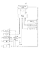
以下、エンジンを走行駆動源とし、アイドリングストップ制御を行う車両に具現化した実施形態について図面を参照しつつ説明する。図1は、車両に搭載されたエンジン制御システムの概略構成図である。 Hereinafter, an embodiment embodied in a vehicle that uses an engine as a travel drive source and performs idling stop control will be described with reference to the drawings. FIG. 1 is a schematic configuration diagram of an engine control system mounted on a vehicle.
図1において、エンジン制御システムは、エンジン(内燃機関)10、充放電可能なバッテリ11、スタータ(モータ)12、オルタネータ(発電機)13、車載の各種電装機器(アクセサリ)である補機14、運転者のイグニッションキー操作により開閉するイグニッションスイッチ(以下、IGスイッチ16と記す)、リレー22、エンジンECU30、アイドリングストップECU(以下、ISS−ECU20と記す)等を備えて構成されている。
In FIG. 1, an engine control system includes an engine (internal combustion engine) 10, a chargeable /
エンジン10は、燃料噴射を行うとともに、燃焼室において燃料と空気の混合気を添加して混合気を燃焼させるものであり、エンジン10の図示を略すクランク軸には、スタータ12が接続されているとともに、ベルト等の連結手段を介してオルタネータ13が連結されている。
The
二次電池であるバッテリ11は、例えば12〜14Vの鉛蓄電池であり、スタータ12や補機14の他、エンジンECU30及びISS−ECU20に電力を供給する。
The
スタータ12は、IGスイッチ16がオンの際、及びアイドリングストップ制御で自動停止されたエンジン10が再始動される際に駆動される。なおスタータ12はリレー22を介してバッテリ11と接続されている。
The
オルタネータ13は、エンジン10の回転に伴って発電し、発電した電力をバッテリ11や補機14へと供給する。補機14は、オルタネータ13とバッテリ11とからの電力供給を受けて駆動される。
The alternator 13 generates power with the rotation of the
IGスイッチ16は、車両の電源状態を切り替えるためのものであり、図示を略すイグニッションキーの回転操作等によって、オフ位置、イグニッション(IG)位置、及びスタート位置に切り替えられる。
The
IGスイッチ16がオフ位置の場合、バッテリ11から各機器への電力供給が停止される。IGスイッチ16がIG位置の場合、エンジンECU30や、車載の各種機器へ電力が供給される。IGスイッチ16がスタート位置の場合、リレー22が通電されて、バッテリ11からスタータ12に電力が供給され、スタータ12によるエンジン10のクランキングが開始する。
When the
なお、IGスイッチ16がIG位置又はスタート位置の場合、IGスイッチ16から、エンジンECU30とISS−ECU20とに対して、スタータ12が駆動中であることを示す信号が送信される。
When the
エンジンECU30は、中央処理装置(CPU)及び記憶装置(ROM及びRAM)、不揮発性のフラッシュメモリ等よりなるマイクロコンピュータを主体として構成されており、車両の運転状態を検出する各種センサからの信号を取り込んで、エンジン10の運転状態を制御する。例えば、車速を検出する車速センサ19、シフトレバーの位置を検出するシフトポジションセンサ18、ブレーキの踏み込みを検出するブレーキセンサ21の他、エンジン10の冷却水温を検出するための水温センサや、クランク角センサ、アクセルセンサ等からの信号を取り込む。そしてROM等に記憶された制御プログラム等を実行して、エンジン10の運転状態を制御する。例えば、燃料噴射量制御、点火時期制御などを制御する。
The engine ECU 30 is mainly configured by a microcomputer including a central processing unit (CPU), a storage device (ROM and RAM), a non-volatile flash memory, and the like, and receives signals from various sensors that detect the driving state of the vehicle. It takes in and controls the operating state of the
また、エンジンECU30は、信号線L1を介してISS−ECU20と接続されており、ISS−ECU20との双方向通信によって互いに情報伝達がされるように構成されている。これによりエンジンECU30が取得した各種センサからの検出信号は、信号線L1を介してISS−ECU20にも入力される。
The engine ECU 30 is connected to the ISS-ECU 20 via the signal line L1, and is configured to transmit information to each other by bidirectional communication with the ISS-ECU 20. Thereby, detection signals from various sensors acquired by the
ISS−ECU20は、中央処理装置(CPU)及び記憶装置(ROM及びRAM)、不揮発性のフラッシュメモリ等よりなるマイクロコンピュータを主体として構成されている。ISS−ECU20は、エンジンECU30が取得した車両の運転状態の検出信号に基づいて、所定の自動停止条件が成立した際にエンジン10の燃焼を停止して、エンジン10を自動停止させる。また、エンジン10の自動停止後、所定の自動再始動条件が成立した際に、スタータ12の駆動やエンジン10の燃焼を再開させる。
The ISS-ECU 20 is mainly configured by a microcomputer including a central processing unit (CPU), a storage device (ROM and RAM), a nonvolatile flash memory, and the like. The ISS-ECU 20 stops the combustion of the
またISS−ECU20は、エンジン運転に伴い駆動される各種アクチュエータの車体における各収容個所に設けられた複数の開閉部の開閉状態の情報を取り込んで、アイドリングストップ制御によるエンジン10の自動停止や再始動を実施するか否かを判定する。すなわち、複数の開閉部の全てが閉状態の場合には、アイドリングストップ制御による自動停止を実施すると判定し、複数の開閉部のいずれかが開状態の場合には、アイドリングストップ制御による自動停止を実施しないと判定する。またエンジン10の自動停止状態で、複数の開閉部のいずれかが開状態となった場合には、エンジン10の再始動を許可(実施)しないと判定する。
Further, the ISS-ECU 20 takes in information on the open / closed states of a plurality of open / close portions provided at the respective housing locations in the vehicle body of the various actuators driven by the engine operation, and automatically stops or restarts the
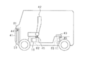
図2に車体に設けられた複数の開閉部の配置例の概略図を示す。図3に複数の開閉部の開閉状態を検出する検出回路の回路図を示す。図2の例では、ラジエータの冷却ファン23が収容された収容部S1に、開閉部41として開閉扉が設けられている。また、車室内の座席下に設けられたエンジン10の収容部S2(エンジンルーム)に、開閉部42としての座席が設けられている。更には、車体の荷室に設けられたバッテリ11の収容部S3(バッテリ収容部)に、開閉部43として開閉扉が設けられている。また、各開閉部41〜43には、その開閉状態を検出する検出部としてのスイッチ44〜46がそれぞれ設けられている。
FIG. 2 shows a schematic diagram of an arrangement example of a plurality of opening / closing sections provided on the vehicle body. FIG. 3 shows a circuit diagram of a detection circuit for detecting the open / closed state of a plurality of open / close sections. In the example of FIG. 2, an opening / closing door is provided as the opening /
図3において、検出回路40は、各開閉部41〜43に設けられたスイッチ44〜46と、各スイッチ44〜46を接続する信号線L2,L3と、分圧抵抗51と、プルアップ抵抗52と、検出回路40の信号をISS−ECU20へ出力する出力端子48と、を備えている。
In FIG. 3, the
具体的には、スイッチ44とスイッチ45とが信号線L2を介して接続され、スイッチ45とスイッチ46とが信号線L3を介して接続されている。これにより各スイッチ44〜46は直列接続されている。また、スイッチ44の他端は分圧抵抗51を介してアース(例えば車両のボディアース)に接続されている。スイッチ46の他端は出力端子48に接続されており、出力端子48がISS−ECU20に接続されている。そして、スイッチ46と出力端子48との間のノード46aは、プルアップ抵抗52を介して定電圧Vccに接続されている。なお定電圧Vccは、DC/DCコンバータでバッテリ11の電圧が所定電圧(例えば5V)に降圧したものとなっている。
Specifically, the
各スイッチ44〜46は、各開閉部41〜43が閉状態の際にオン(導通)となり、開状態の際にオフ(非導通)となる。したがって、検出回路40は、全スイッチ44〜46がオンの際に導通状態となり、スイッチ44〜46のいずれかがオフの際に非導通状態となる。
The
出力端子48は、検出回路40の状態に応じて異なる電圧Vを出力する。すなわち、検出回路40が導通状態の場合には、定電圧Vcc,分圧抵抗51の抵抗R1及びプルアップ抵抗52の抵抗R2で定められる第1電圧V1=Vcc×R1/(R1+R2)を出力する。検出回路40が非導通状態の場合には、定電圧Vcc及び抵抗R2で定められる第2電圧V2(=Vcc)を出力する。なお、第1電圧V1≠第2電圧V2である。
The
これによりISS−ECU20は、出力端子48の電圧Vに基づき取得される検出回路40の状態に応じて、エンジン10の自動停止及び再始動を許可するか否かを判定することができる。すなわち、検出回路40が導通状態であり、出力端子48が第1電圧V1の場合には、アイドリングストップ制御による自動停止及び再始動を許可すると判定する。検出回路40が非導通状態であり、出力端子48の電圧Vが第2電圧V2の場合には、アイドリングストップ制御による自動停止及び再始動を許可しないと判定する。
Thereby, the ISS-
ところで、検出回路40において、信号線L2,L3が断線したり、回路が短絡したりする等の異常が生じることが想定される。この場合、検出回路40の電圧レベル(出力端子48の電圧V)が不安定となり、アイドリングストップ制御による自動停止の要否の判定を適切に実施できなくなるおそれがある。
By the way, in the
そこで、本実施形態では、検出回路40にプルアップ抵抗52を設けることによって、検出回路40に断線や短絡等の異常が生じた場合における出力端子48の電圧Vを規定することとしている。すなわち、検出回路40に断線が生じた場合には、出力端子48の電圧Vは、プルアップ抵抗52により引き上げられて第2電圧V2とし、検出回路40に短絡(地絡)が生じた場合の出力端子48の電圧Vを接地電圧(第3電圧V3)としている。すなわち、検出回路40に異常が生じた場合、その異常の状態に応じて、出力端子48から出力される電圧Vが決定される。
Therefore, in the present embodiment, by providing the
この場合、ISS−ECU20は、出力端子48の電圧Vに応じてアイドリングストップ制御を実施するか否かを判定する。すなわち電圧Vが第1電圧V1の場合には、アイドリングストップ制御を許可すると判定し、出力端子48の電圧Vが第2電圧V2又は第3電圧V3の場合には、アイドリングストップ制御を許可しないと判定する。これにより、開閉部41〜43の全てが閉状態であり且つ検出回路40が正常の場合にのみ、アイドリングストップ制御が許可されるようになり、ひいては、アイドリングストップ制御の信頼性を高めることができる。
In this case, the ISS-
図4に、検出回路40の各状態と出力端子48の電圧Vとの関係の説明図を示す。なお図4では、検出回路40における分圧抵抗51の抵抗R1=1kΩ、プルアップ抵抗52の抵抗R2=4kΩ、定電圧Vcc=5Vであり、出力端子48における第1電圧V1=1V、第2電圧V2=5V、第3電圧V3=0Vとなる例を示している。なお図4において、各スイッチ44〜46が導通状態の場合を「1」、各スイッチ44〜46が非導通状態の場合を「0」と示している。
FIG. 4 is an explanatory diagram showing the relationship between each state of the
検出回路40が正常の場合には、全開閉部41〜43が閉状態であれば(全スイッチ44〜46が導通状態であれば)、出力端子48からは第1電圧V1=1Vが出力される。また開閉部41〜43のいずれかが開状態であれば、出力端子48からは第2電圧V2が出力される。一方、検出回路40に断線又は天絡の異常が生じている場合には、開閉部41〜43の開閉状態に関わらず、出力端子48からは第2電圧V2=5Vが出力される。一方、検出回路40に地絡の異常が生じている場合には、開閉部41〜43の開閉状態に関わらず、出力端子48からは第3電圧V3=0出力される。
When the
すなわち検出回路40が正常であり、且つ全開閉部41〜43が閉状態の場合にのみ、出力端子48から第1電圧V1が出力される。この場合、ISS−ECU20は、出力端子48の電圧Vが第1電圧V1(1V)の場合に、アイドリングストップ制御による自動停止及び再始動を許可することで、開閉部41〜43のいずれかが開状態又は検出回路40に異常がある場合におけるアイドリングストップ制御の実施が回避される。
That is, the first voltage V <b> 1 is output from the
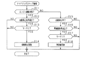
次に以上の構成を備えるエンジン制御システムにおけるアイドリングストップ処理について説明する。図5はアイドリングストップ処理のフローチャートである。 Next, idling stop processing in the engine control system having the above configuration will be described. FIG. 5 is a flowchart of the idling stop process.
図5において、ステップS11でエンジン10が運転状態であるか否かを判定する。例えば、クランク角センサによるクランク軸の回転速度が所定以上の場合に、エンジン10が運転状態であると判定する。
In FIG. 5, it is determined in step S11 whether or not the
肯定判定した場合にはステップS12に進み、自動停止条件として、ブレーキセンサ21によるブレーキ操作が検出されていること、車速が所定未満(10km/h未満)であることの各条件が成立しているかを判定する。 If an affirmative determination is made, the process proceeds to step S12, and whether the brake operation by the brake sensor 21 is detected and the vehicle speed is less than a predetermined value (less than 10 km / h) are satisfied as automatic stop conditions. Determine.
肯定判定した場合には、ステップS13に進み、検出回路40による検出電圧(出力端子48の電圧V)が、全開閉部41〜43が閉状態であることを示す第1電圧V1であるか否かを判定する。これらのステップS12及びS13の両方を肯定判定した場合、自動停止条件が成立したとして、エンジン10を自動停止する。
When an affirmative determination is made, the process proceeds to step S13, and whether or not the detection voltage (voltage V of the output terminal 48) by the
一方、ステップS13で否定判定した場合、すなわち出力端子48の電圧Vが第2電圧V2又は第3電圧V3の場合には、エンジン10の自動停止を実施せずに本処理を終了する。
On the other hand, if a negative determination is made in step S13, that is, if the voltage V of the
一方、ステップS11で否定判定した場合には、ステップS15に進みエンジン10が自動停止中であるか否かを判定する。肯定判定した場合には、ステップS16に進み、再始動条件が成立したか否かを判定する。例えば、ブレーキセンサ21からの信号に基づき、ブレーキが離されたか否かを判定する。肯定判定した場合にはステップS17に進み、検出回路40の電圧Vが第1電圧V1であるか否かを判定する。これらのステップS16及びS17の両方を肯定判定した場合には、自動再始動条件が成立したとして、ステップS18に進み、エンジン10の自動再始動を実施する。一方、ステップS17で否定判定した場合、すなわち出力端子48の電圧Vが第2電圧V2又は第3電圧V3の場合には、エンジン10の再始動を実施せずに本処理を終了する。なお、ステップS12,S13,S15〜S17で否定判定した場合にも本処理を終了する。
On the other hand, if a negative determination is made in step S11, the process proceeds to step S15 to determine whether or not the
上記によれば以下の優れた効果を奏する。 According to the above, the following excellent effects are exhibited.
(1)検出回路40において、複数のスイッチ44〜46を信号線L2,L3により互いに直列接続する構成にしたため、複数の開閉部41〜43の開閉をまとめて検出でき、開閉部41〜43の開閉の検出に関して構成の簡素化を図ることができる。この場合、アイドリグストップ制御の実施を想定すると、複数の開閉部41〜43のうちいずれか1つでも開状態になっていると自動停止や再始動を停止すべきであり、各開閉部41〜43の開閉を検出することの必要性を考慮しても好適な開閉検出を実施できることとなる。
(1) In the
(2)検出回路40に断線や天絡が生じた場合においてエンジン10の自動停止や再始動を行わせないようにすることができ、アイドリグストップ制御を適正に実施できる。
(2) It is possible to prevent the
(3)複数の開閉部41〜43の全閉時、少なくとも1つの開放時、地絡時のそれぞれについて出力電圧を相違させる構成にしたため、アイドリグストップ制御を適正に実施できる。また、地絡の検出も可能になっている。
(3) Since the output voltage is made different for each of when the plurality of opening /
本発明は、上記実施形態の記載内容に限定されず、次のように実施されてもよい。 The present invention is not limited to the description of the above embodiment, and may be implemented as follows.
・上記ではスイッチ毎に検出回路を設ける構成と比べて、各スイッチ44〜46を直列接続し、その直列回路の一端の電圧を検出することで、複数の各開閉部41〜43の開閉状態を検出する検出回路40の構成が簡略化されている。これ以外にも、複数の各スイッチをコンパレータを介して並列接続するとともに、コンパレータの出力端子と定電圧Vccとの間にプルアップ抵抗52を接続することで、車両に複数の開閉部41〜43が設けられている場合における検出回路40の構成を簡略化することができる。
-In the above, compared with the configuration in which a detection circuit is provided for each switch, the
・上記のスイッチ44〜46に変えて、各開閉部41〜43にセンサが設けられてもよい。この場合、各センサを直列接続したり、コンパレータで並列接続したりすることで、車両に複数の開閉部が設けられている場合における構成の簡略化を実現できる。
A sensor may be provided in each of the open /
・検出回路40は、プルダウン回路であてもよい。例えば図3におけるノード46aを接地側に接続するとともに、分圧抵抗51を定電圧側に接続する。この場合、検出回路40に断線などが生じた場合の出力端子48の電圧Vは第3電圧V3となる。
The
・自動停止条件と再始動条件のうち、自動停止条件のみ全開閉部41〜43が閉じていることが条件に含まれていてもよく、再始動条件のみ全開閉部41〜43が閉じていることが条件に含まれるようにしてもよい。
-Among automatic stop conditions and restart conditions, it may be included in the condition that all open /
・検出回路40は、複数の開閉部のいずれかが開状態であるか、検出回路40に異常が生じている異常時の際に、これらの異常がない正常時とは異なる電圧(状態)となる構成であればよく、ISS−ECU20は、正常時の電圧V(状態)とは異なる電圧(状態)を検出した際に、アイドリングストップ制御を許可しないと判定するものであればよい。
The
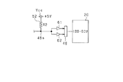
例えば、図6の変用例の検出回路40の回路図に示されるように、図3の検出回路40の構成において、ノード46aと出力端子48との間に、第1コンパレータ61と第2コンパレータ62との並列接続を設ける。例えば第1コンパレータは、電圧Vが4.5V未満の際にハイレベルとなり、4.5V以上の際にローレベルとなる。第2コンパレータ62は、電圧Vが0.5V以上の際にハイレベルとなり、0.5V未満の際にローレベルとなる。なお上述と同様、異常時における第2電圧V2=5V、第3電圧V3=0Vとしている。すなわち、正常時には第1コンパレータ61及び第2コンパレータ62の両方がハイレベルとなり、異常時には第1コンパレータ61及び第2コンパレータ62のいずれかがローレベルとなる。この場合、ISS−ECU20は、出力端子48を介して入力された第1コンパレータ61及び第2コンパレータ62の両方の状態がハイレベルの場合に、アイドリングストップ制御を許可すると判定し、第1コンパレータ61及び第2コンパレータ62のいずれかがローレベルの際に、アイドリングストップ制御を許可しないと判定することができる。
For example, as shown in the circuit diagram of the
10…エンジン、11…バッテリ、40…検出回路、41…開閉部、42…開閉部、43…開閉部、44…スイッチ、45…スイッチ、46…スイッチ、52…プルアップ抵抗、ECU…アイドリングストップ。
DESCRIPTION OF
Claims (5)
前記検出回路の検出結果を所定の自動停止条件及び所定の再始動条件の少なくともいずれかとして含み、これら自動停止条件、再始動条件の成否に基づいて、エンジン(10)の自動停止及び再始動を実施するアイドリングストップ制御手段(20)と、
を備え、
前記検出回路は、
複数の前記開閉部にそれぞれ設けられ、信号線により互いに直列又は並列に接続された複数の検出部(44〜46)と、
前記複数の検出部の直列回路又は並列回路の出力端の側に設けられ、出力端電圧をプルアップ又はプルダウンする電圧調整手段(52)と、
を有することを特徴とするエンジン制御システム。 A detection circuit (40) for detecting an open / closed state of the open / close sections (41-43) provided in the vehicle body;
The detection result of the detection circuit is included as at least one of a predetermined automatic stop condition and a predetermined restart condition, and the engine (10) is automatically stopped and restarted based on the success or failure of the automatic stop condition and the restart condition. An idling stop control means (20) to be implemented;
With
The detection circuit includes:
A plurality of detection units (44 to 46) provided in each of the plurality of opening and closing units and connected to each other in series or in parallel by signal lines;
Voltage adjusting means (52) provided on the output end side of the series circuit or parallel circuit of the plurality of detection units, and pulling up or pulling down the output end voltage;
An engine control system comprising:
Priority Applications (1)
| Application Number | Priority Date | Filing Date | Title |
|---|---|---|---|
| JP2014030368A JP2015155658A (en) | 2014-02-20 | 2014-02-20 | engine control system |
Applications Claiming Priority (1)
| Application Number | Priority Date | Filing Date | Title |
|---|---|---|---|
| JP2014030368A JP2015155658A (en) | 2014-02-20 | 2014-02-20 | engine control system |
Publications (1)
| Publication Number | Publication Date |
|---|---|
| JP2015155658A true JP2015155658A (en) | 2015-08-27 |
Family
ID=54775102
Family Applications (1)
| Application Number | Title | Priority Date | Filing Date |
|---|---|---|---|
| JP2014030368A Pending JP2015155658A (en) | 2014-02-20 | 2014-02-20 | engine control system |
Country Status (1)
| Country | Link |
|---|---|
| JP (1) | JP2015155658A (en) |
Citations (7)
| Publication number | Priority date | Publication date | Assignee | Title |
|---|---|---|---|---|
| JPS5942724A (en) * | 1982-09-01 | 1984-03-09 | オムロン株式会社 | Switch open detecting system |
| JP2001107768A (en) * | 1999-10-05 | 2001-04-17 | Toyota Motor Corp | Jumper start judging device and vehicular control device |
| JP2004122246A (en) * | 2002-09-30 | 2004-04-22 | Ckd Corp | State detector and machine tool |
| JP2004344294A (en) * | 2003-05-21 | 2004-12-09 | Toshiba Corp | Washing machine |
| JP2008232978A (en) * | 2007-03-23 | 2008-10-02 | Mitsubishi Electric Corp | Wiring abnormality detecting device |
| JP2012121520A (en) * | 2010-12-10 | 2012-06-28 | Jvc Kenwood Corp | On-board device and key identification method |
| JP2013155665A (en) * | 2012-01-30 | 2013-08-15 | Suzuki Motor Corp | Control device for vehicle |
-
2014
- 2014-02-20 JP JP2014030368A patent/JP2015155658A/en active Pending
Patent Citations (7)
| Publication number | Priority date | Publication date | Assignee | Title |
|---|---|---|---|---|
| JPS5942724A (en) * | 1982-09-01 | 1984-03-09 | オムロン株式会社 | Switch open detecting system |
| JP2001107768A (en) * | 1999-10-05 | 2001-04-17 | Toyota Motor Corp | Jumper start judging device and vehicular control device |
| JP2004122246A (en) * | 2002-09-30 | 2004-04-22 | Ckd Corp | State detector and machine tool |
| JP2004344294A (en) * | 2003-05-21 | 2004-12-09 | Toshiba Corp | Washing machine |
| JP2008232978A (en) * | 2007-03-23 | 2008-10-02 | Mitsubishi Electric Corp | Wiring abnormality detecting device |
| JP2012121520A (en) * | 2010-12-10 | 2012-06-28 | Jvc Kenwood Corp | On-board device and key identification method |
| JP2013155665A (en) * | 2012-01-30 | 2013-08-15 | Suzuki Motor Corp | Control device for vehicle |
Similar Documents
| Publication | Publication Date | Title |
|---|---|---|
| JP5477409B2 (en) | Power system | |
| US9234470B2 (en) | Idling stop device, power control method, deterioration notification method and battery charging method | |
| US8689758B2 (en) | Starter control apparatus | |
| JP2007259645A (en) | Battery controller | |
| US10259449B2 (en) | Method for operating a drive device and corresponding hybrid drive device | |
| US10302060B2 (en) | Electric power control apparatus | |
| US9977086B2 (en) | Battery monitoring apparatus | |
| JP4984163B2 (en) | Fuel injection control device | |
| US7156064B2 (en) | Engine starting control apparatus and starting control method | |
| JP2015120462A (en) | Device for controlling vehicle | |
| JP2015174552A (en) | Monitoring device for residual capacity of battery | |
| JP5786787B2 (en) | In-vehicle control system | |
| US11332024B2 (en) | Proximity detection arrangement and method | |
| CN107813779B (en) | Power supply device for vehicle | |
| JP2015155658A (en) | engine control system | |
| JP2013199908A (en) | Starter control device | |
| JP2015123823A (en) | Vehicular power supply device | |
| JP4107611B2 (en) | Internal combustion engine control device | |
| JP6167886B2 (en) | Engine control device | |
| JP5673578B2 (en) | Vehicle control device | |
| JP5533916B2 (en) | Starter control device | |
| JP6851743B2 (en) | Jumping start judgment device | |
| US20190170079A1 (en) | Control device of fuel pump | |
| JP6682383B2 (en) | Vehicle control device | |
| JP5278485B2 (en) | Idling stop control device |
Legal Events
| Date | Code | Title | Description |
|---|---|---|---|
| A621 | Written request for application examination |
Free format text: JAPANESE INTERMEDIATE CODE: A621 Effective date: 20160331 |
|
| A977 | Report on retrieval |
Free format text: JAPANESE INTERMEDIATE CODE: A971007 Effective date: 20170228 |
|
| A131 | Notification of reasons for refusal |
Free format text: JAPANESE INTERMEDIATE CODE: A131 Effective date: 20170307 |
|
| A521 | Request for written amendment filed |
Free format text: JAPANESE INTERMEDIATE CODE: A523 Effective date: 20170419 |
|
| A131 | Notification of reasons for refusal |
Free format text: JAPANESE INTERMEDIATE CODE: A131 Effective date: 20170620 |
|
| A02 | Decision of refusal |
Free format text: JAPANESE INTERMEDIATE CODE: A02 Effective date: 20171212 |