JP2015114751A - Writing data processor - Google Patents

Writing data processor Download PDF

Info

Publication number
JP2015114751A
JP2015114751A JP2013254869A JP2013254869A JP2015114751A JP 2015114751 A JP2015114751 A JP 2015114751A JP 2013254869 A JP2013254869 A JP 2013254869A JP 2013254869 A JP2013254869 A JP 2013254869A JP 2015114751 A JP2015114751 A JP 2015114751A
Authority
JP
Japan
Prior art keywords
state
cpu
writing
data
coordinate data
Prior art date
Legal status (The legal status is an assumption and is not a legal conclusion. Google has not performed a legal analysis and makes no representation as to the accuracy of the status listed.)
Pending
Application number
JP2013254869A
Other languages
Japanese (ja)
Inventor
伊藤 千年
Chitoshi Ito
千年 伊藤
Current Assignee (The listed assignees may be inaccurate. Google has not performed a legal analysis and makes no representation or warranty as to the accuracy of the list.)
Brother Industries Ltd
Original Assignee
Brother Industries Ltd
Priority date (The priority date is an assumption and is not a legal conclusion. Google has not performed a legal analysis and makes no representation as to the accuracy of the date listed.)
Filing date
Publication date
Application filed by Brother Industries Ltd filed Critical Brother Industries Ltd
Priority to JP2013254869A priority Critical patent/JP2015114751A/en
Publication of JP2015114751A publication Critical patent/JP2015114751A/en
Pending legal-status Critical Current

Links

Images

Abstract

PROBLEM TO BE SOLVED: To provide a writing data processor capable of easily creating a new image file including specific handwriting and added writing even after an image file showing the specific handwriting is once created.SOLUTION: The CPU of a reader acquires coordinate data capable of specifying a position at which a writing instrument is approached (S23); stores the coordinate data in RAM when the coordinate data show the position of an entry region (S27); determines whether the writing instrument is in a first state or a second state (S29) when the coordinate data show the position of a check region (S25:YES); creates stroke data on the basis of the coordinate data stored in the RAM (S31) when determined that the writing instrument is in the first state (S29:YES); and creates stroke data on the basis of coordinate data corresponding to the stroke data and the coordinate data stored in the RAM (S45) when determined that the writing instrument is in the second state (S29:NO).

Description

本発明は、紙媒体に筆記する動作に基づき、筆記具の移動の軌跡を電子化する筆記データ処理装置に関する。   The present invention relates to a writing data processing apparatus that digitizes a movement trajectory of a writing instrument based on an operation of writing on a paper medium.

台座上に載置された紙媒体に筆記具で筆記する場合の筆記具の動作に基づいて、筆記具の移動の軌跡を筆跡として電子化することが可能な筆記データ処理装置が知られている。例えば特許文献1には、紙媒体のうち自由入力欄に相当する部分にペンで筆記された場合に、ペン先の位置を示す複数の座標データを特定し、特定された複数の座標データに基づいて、筆跡を示すビットマップ形式の画像ファイルを作成する筆記データ処理装置が提案されている。   2. Description of the Related Art A writing data processing apparatus is known that can digitize a movement trajectory of a writing instrument as a handwriting based on the operation of the writing instrument when writing on a paper medium placed on a pedestal. For example, Patent Document 1 specifies a plurality of coordinate data indicating the position of a pen tip when a pen is written on a portion corresponding to a free input field of a paper medium, and based on the plurality of specified coordinate data. Thus, a handwritten data processing apparatus has been proposed that creates a bitmap-format image file indicating handwriting.

特開2005−301860号公報JP 2005-301860 A

ユーザがペンで紙媒体に1回目の筆記を行うことによって、上記装置において第1の筆跡を示す第1の画像ファイルが作成され、その後、ユーザがペンで紙媒体に2回目の筆記を行い、第1の筆跡に第2の筆跡を追記した場合を例に挙げる。この場合、上記装置では、第1の筆跡とは異なる第2の筆跡を示す第2の画像ファイルが新たに作成される。第2の画像ファイルによって示される筆跡に第1の筆跡は含まれない。このように、上記装置では、画像ファイルが一旦作成された場合、作成された画像ファイルによって示される筆跡に別の筆跡が追記された新たな画像ファイルを容易に作成できないという問題点がある。   When the user performs the first writing on the paper medium with the pen, a first image file indicating the first handwriting is created in the device, and then the user performs the second writing on the paper medium with the pen, A case where the second handwriting is added to the first handwriting is taken as an example. In this case, in the device, a second image file indicating a second handwriting different from the first handwriting is newly created. The handwriting indicated by the second image file does not include the first handwriting. As described above, the above-described apparatus has a problem in that once an image file is created, a new image file in which another handwriting is added to the handwriting indicated by the created image file cannot be easily created.

本発明の目的は、特定の筆跡を示す画像ファイルが一旦作成された後でも、特定の筆跡と追記された筆記とを含む新たな画像ファイルを容易に作成できる筆記データ処理装置を提供することである。   An object of the present invention is to provide a writing data processing device that can easily create a new image file including a specific handwriting and an additionally written writing even after an image file indicating the specific writing is once created. is there.

本発明の第1態様に係る筆記データ処理装置は、紙媒体が載置される所定領域の何れかの位置に、前記紙媒体への筆記が可能な第1状態と、前記紙媒体への筆記が不可能な第2状態とに切り替え可能な筆記具が近接した場合に、前記筆記具が近接した位置を検出する検出部と、前記検出部によって検出された位置を特定可能な座標データを取得する取得手段と、前記取得手段によって取得された前記座標データが所定の条件を満たすか判断する第1判断手段と、前記第1判断手段によって、前記座標データが前記所定の条件を満たすと判断された場合、前記筆記具が前記第1状態であるか又は前記第2状態であるかを判断する第2判断手段と、前記第2判断手段によって前記第1状態であると判断された場合、前記紙媒体に筆記された第1線画の位置を示す複数の前記座標データを含む第1ストロークデータファイルを作成する第1作成手段と、前記第2判断手段によって前記第2状態であると判断された場合、前記第1作成手段によって作成された前記第1ストロークデータファイルに含まれる前記複数の座標データに、前記紙媒体に新たに筆記された第2線画の位置を示す複数の前記座標データを含めたストロークデータファイルであって、前記第1線画に前記第2線画が追記された線画を示す第2ストロークデータファイルを作成する第2作成手段とを備えている。   The writing data processing apparatus according to the first aspect of the present invention includes a first state in which writing on the paper medium is possible at any position in a predetermined area where the paper medium is placed, and writing on the paper medium. When a writing tool that can be switched to the second state in which the writing tool cannot be moved approaches, a detection unit that detects a position at which the writing tool approaches, and acquisition of coordinate data that can specify the position detected by the detection unit A first determining unit that determines whether the coordinate data acquired by the acquiring unit satisfies a predetermined condition; and the first determining unit determines that the coordinate data satisfies the predetermined condition When the writing instrument is determined to be in the first state by the second determination means for determining whether the writing instrument is in the first state or the second state, Written first line A first creation means for creating a first stroke data file including a plurality of the coordinate data indicating the position of the position, and the first creation means if the second judgment means determines that the second state is present. A plurality of coordinate data included in the first stroke data file, the stroke data file including a plurality of the coordinate data indicating the position of the second line drawing newly written on the paper medium, And a second creation means for creating a second stroke data file indicating a line drawing in which the second line drawing is added to the first line drawing.

第1態様によれば、筆記データ処理装置は、所定の条件を満たす座標データが取得された場合、所定領域に近接した筆記具の状態が第1状態であるか又は第2状態であるかを判断する。筆記データ処理装置は、第1状態であると判断した場合、紙媒体に筆記された線画の位置を示す座標データに基づいて第1ストロークデータファイルを作成する。これによって筆記データ処理装置は、筆記具によって紙媒体に筆記された線画のストロークデータファイルを作成できる。一方、筆記データ処理装置は、第2状態であると判断した場合、第1ストロークデータファイルに含まれる座標データと、紙媒体に新たに筆記された線画の位置を示す座標データとに基づいて、第2ストロークデータファイルを作成する。これによって筆記データ処理装置は、筆記具によって先に筆記された線画と後で筆記された線画との両方のストロークデータファイルを作成できる。従ってユーザは、第2状態とした筆記具を所定領域に近接させることによって、紙媒体に先に筆記した線画と後で筆記した線画とのストロークデータファイルを、筆記データ処理装置に作成させることができる。このためユーザは、特定の線画のストロークデータファイルが一旦作成された後でも、特定の線画と追記された線画との両方のストロークデータファイルを、筆記データ処理装置に容易に作成させることができる。   According to the first aspect, when the coordinate data satisfying the predetermined condition is acquired, the writing data processing device determines whether the state of the writing instrument close to the predetermined region is the first state or the second state. To do. When it is determined that the writing data processing device is in the first state, the writing data processing device creates a first stroke data file based on the coordinate data indicating the position of the line drawing written on the paper medium. As a result, the writing data processing apparatus can create a stroke data file of a line drawing written on a paper medium with a writing tool. On the other hand, if the writing data processing device determines that the state is the second state, based on the coordinate data included in the first stroke data file and the coordinate data indicating the position of the line drawing newly written on the paper medium, A second stroke data file is created. As a result, the writing data processing apparatus can create both stroke data files of the line drawing previously written by the writing tool and the line drawing written later. Accordingly, the user can cause the writing data processing device to create a stroke data file of the line drawing previously written on the paper medium and the line drawing written later by bringing the writing tool in the second state close to the predetermined area. . For this reason, even after a stroke data file of a specific line drawing is once created, the user can easily cause the writing data processing apparatus to create both stroke data files of the specific line drawing and the added line drawing.

手書入力システム1の概要を示す図である。It is a figure which shows the outline | summary of the handwriting input system. 共振回路38の回路図である。3 is a circuit diagram of a resonance circuit 38. FIG. 読取装置2及びスマートフォン19の電気的構成を示すブロック図である。3 is a block diagram showing an electrical configuration of a reading device 2 and a smartphone 19. FIG. 用紙123を示す図である。FIG. ファイルリスト231を示す図である。It is a figure which shows the file list. 筆記の手順を示す図である。It is a figure which shows the procedure of writing. メイン処理のフローチャートである。It is a flowchart of a main process.

以下、本発明の実施形態について、図面を参照して説明する。図1を参照して、本実施形態に係る手書入力システム1の概要を説明する。以下の説明では、図1の左上側、右下側、上側、下側、右上側、左下側を、各々、読取装置2の左側、右側、前側、後側、上側、下側と定義して説明する。   Hereinafter, embodiments of the present invention will be described with reference to the drawings. The outline of the handwriting input system 1 according to the present embodiment will be described with reference to FIG. In the following description, the upper left side, lower right side, upper side, lower side, upper right side, and lower left side in FIG. 1 are respectively defined as the left side, right side, front side, rear side, upper side, and lower side of the reader 2. explain.

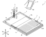
図1に示すように、手書入力システム1は、読取装置2、電子ペン3、スマートフォン19等を主に備える。読取装置2は、折り畳んで携行可能な、薄型軽量の手書き入力装置である。手書入力システム1では、ユーザは電子ペン3を用いて、読取装置2に装着された紙媒体100の用紙111に点や線画を筆記する。以下では、線画が筆記される場合について説明する。線画には、文字、数値、記号、図形等が含まれる。読取装置2は、筆記の過程における電子ペン3の位置を取得する。読取装置2は、取得した位置に基づいてストロークデータを作成する。又、読取装置2は、作成したストロークデータに基づいて、電子ペン3によって用紙111に筆記された線画を特定する。読取装置2は、特定された線画を含む画像の画像ファイルを作成する。読取装置2は、作成した画像ファイルをスマートフォン19に送信することができる。スマートフォン19は、画像ファイルを受信した場合、受信した画像ファイルに対応する画像を、ディスプレイ192に表示させる。これによってユーザは、電子ペン3によって用紙111に筆記された線画と同一形状の線画を、ディスプレイ192を介して視認できる。   As shown in FIG. 1, the handwriting input system 1 mainly includes a reading device 2, an electronic pen 3, a smartphone 19, and the like. The reading device 2 is a thin and light handwritten input device that can be folded and carried. In the handwriting input system 1, the user writes a dot or a line drawing on the paper 111 of the paper medium 100 attached to the reading device 2 using the electronic pen 3. Below, the case where a line drawing is written is demonstrated. The line drawing includes characters, numerical values, symbols, figures, and the like. The reading device 2 acquires the position of the electronic pen 3 in the writing process. The reading device 2 creates stroke data based on the acquired position. Further, the reading device 2 specifies a line drawing written on the paper 111 by the electronic pen 3 based on the created stroke data. The reading device 2 creates an image file of an image including the specified line drawing. The reading device 2 can transmit the created image file to the smartphone 19. When the smartphone 19 receives the image file, the smartphone 19 displays an image corresponding to the received image file on the display 192. Thus, the user can visually recognize a line drawing having the same shape as the line drawing written on the paper 111 with the electronic pen 3 via the display 192.

読取装置2は、左右一対の左読取装置2L,右読取装置2R,及びカバー4を構成の主体とする。左読取装置2L及び右読取装置2Rは、矩形薄板状である。左読取装置2L及び右読取装置2Rは、カバー4の前面に左右方向に見開き可能に配置されている。左読取装置2L及び右読取装置2Rは、フラットケーブル(図示略)によって電気的に接続されている。右読取装置2Rは、3つのLED5を上端に備える。LED5は、読取装置2の状態をユーザに通知可能である。カバー4は、袋状の袋部4Aを左側に備える。左読取装置2Lは、袋部4A内に差し込まれることでカバー4に着脱可能に装着される。右読取装置2Rは、両面テープ及び粘着性を有する樹脂フィルム等によって、カバー4の右前面に貼り付けられる。   The reading device 2 mainly includes a pair of left and right left reading devices 2L, a right reading device 2R, and a cover 4. The left reading device 2L and the right reading device 2R are rectangular thin plates. The left reading device 2L and the right reading device 2R are arranged on the front surface of the cover 4 so as to be spread in the left-right direction. The left reading device 2L and the right reading device 2R are electrically connected by a flat cable (not shown). The right reading device 2R includes three LEDs 5 at the upper end. The LED 5 can notify the user of the state of the reading device 2. The cover 4 includes a bag-like bag portion 4A on the left side. The left reading device 2L is detachably attached to the cover 4 by being inserted into the bag portion 4A. The right reading device 2R is attached to the right front surface of the cover 4 with a double-sided tape and an adhesive resin film.

なお、読取装置2は、右読取装置2Rのみを備えた構成であってもよい。この場合、読取装置2に装着可能な紙媒体100の一例として、A5サイズのレポート用紙が挙げられる。   Note that the reading device 2 may include only the right reading device 2R. In this case, as an example of the paper medium 100 that can be loaded into the reading device 2, A5 size report paper can be cited.

読取装置2の前面には紙媒体100が着脱可能に装着される。紙媒体100は、左右方向に見開き可能な冊子状である。紙媒体100では、一対の表紙(表表紙110L及び裏表紙110R)と複数の用紙111が、各々の縁部の一部で綴じられている。一例として、紙媒体100はA5サイズのノートである。用紙111に予め印刷された図柄のレイアウト等を示すフォーマットは、紙媒体100の種別毎に異なる。又、用紙111のフォーマットは、頁毎に異なる場合もある。以下、用紙111に予め印刷された図柄を、印刷図柄という。紙媒体100は、表表紙110Lが左読取装置2Lの前面に載置され、且つ、裏表紙110Rが右読取装置2Rの前面に載置されるように、読取装置2に装着される。本実施形態では、紙媒体100は、両面テープ及び粘着性を有する樹脂フィルム等によって、紙媒体100が読取装置2に位置決めされた状態で装着される。即ち、左読取装置2L及び右読取装置2Rは各々、表表紙110L及び裏表紙110Rと一体的に移動する。ユーザは電子ペン3を用いて紙媒体100の用紙111に線画を筆記できる。   A paper medium 100 is detachably mounted on the front surface of the reading device 2. The paper medium 100 is a booklet that can be spread in the left-right direction. In the paper medium 100, a pair of front covers (a front cover 110L and a back cover 110R) and a plurality of papers 111 are bound at a part of each edge. As an example, the paper medium 100 is an A5 size notebook. The format indicating the layout or the like of symbols preprinted on the paper 111 is different for each type of the paper medium 100. Further, the format of the paper 111 may be different for each page. Hereinafter, the symbol printed in advance on the paper 111 is referred to as a printed symbol. The paper medium 100 is mounted on the reading device 2 such that the front cover 110L is placed on the front surface of the left reading device 2L and the back cover 110R is placed on the front surface of the right reading device 2R. In the present embodiment, the paper medium 100 is mounted in a state where the paper medium 100 is positioned on the reading device 2 by a double-sided tape, an adhesive resin film, or the like. That is, the left reading device 2L and the right reading device 2R move integrally with the front cover 110L and the back cover 110R, respectively. The user can write a line drawing on the paper 111 of the paper medium 100 using the electronic pen 3.

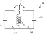
電子ペン3は、電磁誘導式のノック式電子ペンであり、筒体30、芯体31、コイル32、コンデンサ33、35、基板34、インク収納部36、スイッチ37(図2参照)、及び、図示外のノックカムを主に備える。筒体30は、円柱状の形状を有し、芯体31、コイル32,コンデンサ33、35、基板34,インク収納部36、及びスイッチ37を内部に収容する。芯体31は、筒体30の延伸方向に沿って筒体30内を延びる。芯体31の一端部は、電子ペン3の先端側に配置され、芯体31の他端部は、インクが収納されているインク収納部36に接続される。インク収納部36は、芯体31にインクを供給する。芯体31は図示外の弾性部材によって、電子ペン3の先端側に付勢されている。   The electronic pen 3 is an electromagnetic induction type knock type electronic pen, and includes a cylindrical body 30, a core body 31, a coil 32, capacitors 33 and 35, a substrate 34, an ink storage unit 36, a switch 37 (see FIG. 2), and A knock cam (not shown) is mainly provided. The cylindrical body 30 has a cylindrical shape, and houses the core body 31, the coil 32, the capacitors 33 and 35, the substrate 34, the ink storage unit 36, and the switch 37 therein. The core body 31 extends in the cylinder body 30 along the extending direction of the cylinder body 30. One end portion of the core body 31 is disposed on the distal end side of the electronic pen 3, and the other end portion of the core body 31 is connected to an ink storage portion 36 in which ink is stored. The ink storage unit 36 supplies ink to the core body 31. The core body 31 is urged toward the distal end side of the electronic pen 3 by an elastic member (not shown).

ノックカムは図示外のカム本体、ノック棒39、及び図示外の回転子を有する。カム本体は、筒体30のうち電子ペン3の先端側と反対側の内壁に設けられている。ノック棒39は、筒体30の反対側の端部から外側に突出する。回転子は芯体31に接続する。ノック棒39が筒体30の内部に押し込まれた場合、回転子は回転し、カム本体のうち電子ペン3の先端側に引っ掛かる。芯体31は、弾性部材の付勢力に逆らって電子ペン3の先端側に移動し、芯体31の一端部が筒体30から外部に突出した状態でカム本体に保持される。芯体31の一端側が筒体30から外部に突出した状態で、ユーザが電子ペン3を用いて用紙111に筆記すると、インクによって用紙111に線画が形成される。ノック棒39が筒体30の内部に再度押し込まれた場合、回転子は更に回転し、カム本体から外れる。芯体31は弾性部材の付勢力によって電子ペン3の反対側に移動し、芯体31の一端部は筒体30内部に収容される。この状態で、ユーザは電子ペン3によって用紙111に線画を筆記することができない。以下、芯体31の一端部が筒体30から外部に突出した状態を第1状態といい、芯体31の一端部が筒体30内部に収容された状態を第2状態という。   The knock cam has a cam body (not shown), a knock bar 39, and a rotor (not shown). The cam body is provided on the inner wall of the cylindrical body 30 on the side opposite to the tip side of the electronic pen 3. The knock bar 39 projects outward from the opposite end of the cylindrical body 30. The rotor is connected to the core body 31. When the knock bar 39 is pushed into the cylindrical body 30, the rotor rotates and is caught on the tip side of the electronic pen 3 in the cam body. The core body 31 moves to the tip side of the electronic pen 3 against the urging force of the elastic member, and is held by the cam body with one end portion of the core body 31 protruding outside from the cylindrical body 30. When the user writes on the paper 111 using the electronic pen 3 in a state where one end side of the core 31 protrudes from the cylindrical body 30, a line drawing is formed on the paper 111 by the ink. When the knock bar 39 is pushed into the cylinder 30 again, the rotor further rotates and comes off the cam body. The core body 31 is moved to the opposite side of the electronic pen 3 by the biasing force of the elastic member, and one end portion of the core body 31 is accommodated in the cylindrical body 30. In this state, the user cannot write a line drawing on the paper 111 with the electronic pen 3. Hereinafter, a state in which one end portion of the core body 31 protrudes from the cylindrical body 30 is referred to as a first state, and a state in which the one end portion of the core body 31 is accommodated in the cylindrical body 30 is referred to as a second state.

コイル32は、インク収納部36の周囲に巻回されている。コンデンサ33、35は、基板34によって電子ペン3の内部に固定されている。スイッチ37は、電子ペン3の状態(第1状態又は第2状態)に応じてON/OFFする。コイル32、及び、コンデンサ33、35は、スイッチ37を介して周知の共振回路38を構成する。   The coil 32 is wound around the ink storage unit 36. The capacitors 33 and 35 are fixed inside the electronic pen 3 by the substrate 34. The switch 37 is turned ON / OFF according to the state (first state or second state) of the electronic pen 3. The coil 32 and the capacitors 33 and 35 constitute a known resonance circuit 38 via a switch 37.

図2を参照し、共振回路38を説明する。共振回路38は、第1共振回路38A及び第2共振回路38Bを備える。第1共振回路38Aは、コイル32及びコンデンサ33を有する。第2共振回路38Bは、コイル32及びコンデンサ35を有する。コイル32の一端部と、コンデンサ33、35の夫々の一端部とは接続する。コイル32の他端部と、コンデンサ33、35の夫々の他端部との間に、スイッチ37が介在する。スイッチ37は、1回路2接点式のスイッチである。スイッチ37は、電子ペン3が第1状態のとき、即ち、ノックカムが押し込まれて芯体31の一端側が筒体30から外部に突出した状態で、コイル32とコンデンサ33との夫々の他端部同士を導通状態とし、コイル32とコンデンサ35との夫々の他端部同士を非導通状態とする。これによって、第1共振回路38Aは、第1周波数で共振することが可能な状態になる。一方、スイッチ37は、電子ペン3が第2状態のとき、即ち、ノックカムが再度押し込まれて芯体31の一端側が筒体30内部に収容された状態で、コイル32とコンデンサ33との夫々の他端部同士を非導通状態とし、コイル32とコンデンサ35との夫々の他端部同士を導通状態とする。これによって、第2共振回路38Bは、第2周波数で共振することが可能な状態になる。   The resonance circuit 38 will be described with reference to FIG. The resonance circuit 38 includes a first resonance circuit 38A and a second resonance circuit 38B. The first resonance circuit 38 </ b> A includes a coil 32 and a capacitor 33. The second resonance circuit 38B includes a coil 32 and a capacitor 35. One end of the coil 32 is connected to one end of each of the capacitors 33 and 35. A switch 37 is interposed between the other end of the coil 32 and the other end of each of the capacitors 33 and 35. The switch 37 is a one-circuit two-contact switch. The switch 37 is the other end of each of the coil 32 and the capacitor 33 when the electronic pen 3 is in the first state, that is, when the knock cam is pushed in and one end of the core 31 protrudes from the cylindrical body 30. The other ends of the coil 32 and the capacitor 35 are brought into a non-conductive state. As a result, the first resonance circuit 38A can resonate at the first frequency. On the other hand, when the electronic pen 3 is in the second state, that is, when the knock cam is pushed in again and one end side of the core body 31 is accommodated in the cylindrical body 30, the switch 37 is connected to the coil 32 and the capacitor 33. The other end portions are made non-conductive, and the other end portions of the coil 32 and the capacitor 35 are made conductive. As a result, the second resonance circuit 38B can resonate at the second frequency.

図1に示すように、スマートフォン19は、タッチパネル191及びディスプレイ192を備える。タッチパネル191は、各種指示を入力するために使用される。ディスプレイ192は、画像ファイルに対応する画像を表示可能である。なお、スマートフォン19の代わりに汎用PCやタブレットPCが用いられてもよい。   As shown in FIG. 1, the smartphone 19 includes a touch panel 191 and a display 192. The touch panel 191 is used for inputting various instructions. The display 192 can display an image corresponding to the image file. A general-purpose PC or a tablet PC may be used instead of the smartphone 19.

図3を参照して、手書入力システム1の電気的構成を説明する。まず、読取装置2の電気的構成と、読取装置2が座標データを検出する原理の概要とを説明する。読取装置2は、センサ基板7L,7R,メイン基板20,センサ制御基板28,29、入力部25、及び3つのLED5を備える。センサ基板7L,7Rは、夫々、左読取装置2L,右読取装置2R内に設けられる。入力部25及び3つのLED5は、右読取装置2Rに設けられる。   The electrical configuration of the handwriting input system 1 will be described with reference to FIG. First, the electrical configuration of the reading device 2 and the outline of the principle by which the reading device 2 detects coordinate data will be described. The reading device 2 includes sensor boards 7L and 7R, a main board 20, sensor control boards 28 and 29, an input unit 25, and three LEDs 5. The sensor substrates 7L and 7R are provided in the left reading device 2L and the right reading device 2R, respectively. The input unit 25 and the three LEDs 5 are provided in the right reading device 2R.

メイン基板20は、CPU21、RAM22、フラッシュROM23、及び無線通信部24を備える。RAM22、フラッシュROM23、及び無線通信部24は、CPU21に電気的に接続されている。CPU21は、読取装置2の制御を行う。RAM22は、演算データ等の各種データを一時的に記憶する。フラッシュROM23には、CPU21が読取装置2を制御するために実行するプログラムが記憶される。又、フラッシュROM23には、後述するファイルリスト231(図5参照)が記憶される。又、フラッシュROM23には、用紙111のフォーマット毎にレイアウトデータが複数記憶される。無線通信部24は、外部の電子機器と近距離無線通信を実行するためのコントローラである。入力部25及び3つのLED5は、CPU21に電気的に接続されている。入力部25は、読取装置2に対する指示を入力するためのスイッチである。3つのLED5の夫々の色は、黄色、緑色、及び赤色である。   The main board 20 includes a CPU 21, a RAM 22, a flash ROM 23, and a wireless communication unit 24. The RAM 22, flash ROM 23, and wireless communication unit 24 are electrically connected to the CPU 21. The CPU 21 controls the reading device 2. The RAM 22 temporarily stores various data such as calculation data. The flash ROM 23 stores a program executed by the CPU 21 to control the reading device 2. The flash ROM 23 stores a file list 231 (see FIG. 5) described later. The flash ROM 23 stores a plurality of layout data for each format of the paper 111. The wireless communication unit 24 is a controller for executing short-range wireless communication with an external electronic device. The input unit 25 and the three LEDs 5 are electrically connected to the CPU 21. The input unit 25 is a switch for inputting an instruction to the reading device 2. The respective colors of the three LEDs 5 are yellow, green, and red.

センサ基板7L、7Rには、上下方向及び左右方向の各々に細長いループコイルが多数配列されている。センサ基板7Lは、センサ制御基板28のASIC28Aに電気的に接続されている。ASIC28Aは、電子ペン3による筆記動作がセンサ基板7L上で行われた場合に、電子ペン3の位置を示す座標データを検出する。センサ基板7Rは、センサ制御基板29のASIC29Aに電気的に接続されている。ASIC29Aは、電子ペン3による筆記動作がセンサ基板7R上で行われた場合に、電子ペン3の位置を示す座標データを検出する。ASIC28A,29Aのうち、マスター側のASIC28AはCPU21に直接接続され、スレーブ側のASIC29AはASIC28Aを介してCPU21に接続されている。   A large number of elongated loop coils are arranged in each of the vertical and horizontal directions on the sensor boards 7L and 7R. The sensor board 7L is electrically connected to the ASIC 28A of the sensor control board 28. The ASIC 28A detects coordinate data indicating the position of the electronic pen 3 when a writing operation by the electronic pen 3 is performed on the sensor substrate 7L. The sensor board 7R is electrically connected to the ASIC 29A of the sensor control board 29. The ASIC 29A detects coordinate data indicating the position of the electronic pen 3 when a writing operation by the electronic pen 3 is performed on the sensor substrate 7R. Of the ASICs 28A and 29A, the ASIC 28A on the master side is directly connected to the CPU 21, and the ASIC 29A on the slave side is connected to the CPU 21 via the ASIC 28A.

センサ基板7L,7R上で電子ペン3による筆記動作が行われた場合に座標データが検出される原理を、概略的に説明する。CPU21は、ASIC28A,29Aを制御して、センサ基板7L,7Rの各々のループコイルに、一本ずつ第1周波数の電流(励磁用送信電流)を流す。これにより、センサ基板7L,7Rの各々のループコイルから磁界が発生する。この状態で、例えばユーザが、電子ペン3を第1状態とし、読取装置2に装着された紙媒体100の用紙111に線画を筆記する動作を行うと、電子ペン3はセンサ基板7L,7Rに近接する。そのため、電子ペン3の第1共振回路38A(図2参照)は電磁誘導によって共振し、誘導磁界を生じる。   The principle by which coordinate data is detected when a writing operation with the electronic pen 3 is performed on the sensor substrates 7L and 7R will be schematically described. The CPU 21 controls the ASICs 28A and 29A to flow a first frequency current (excitation transmission current) to each loop coil of the sensor substrates 7L and 7R. Thereby, a magnetic field is generated from each loop coil of the sensor substrates 7L and 7R. In this state, for example, when the user sets the electronic pen 3 to the first state and performs an operation of writing a line drawing on the paper 111 of the paper medium 100 mounted on the reading device 2, the electronic pen 3 is placed on the sensor boards 7L and 7R. Proximity. Therefore, the first resonance circuit 38A (see FIG. 2) of the electronic pen 3 resonates due to electromagnetic induction and generates an induced magnetic field.

次に、CPU21はASIC28A,29Aを制御して、センサ基板7L,7Rの各々のループコイルからの磁界の発生を停止させる。センサ基板7L,7Rの各々のループコイルは、電子ペン3の第1共振回路38Aから発せられる誘導磁界を受信する。CPU21はASIC28A,29Aを制御して、センサ基板7L,7Rの各々のループコイルに流れる信号電流(誘導電流)を検出させる。ASIC28A,29Aがこの動作を全てのループコイルについて一本ずつ実行し、誘導電流を検出することによって、第1状態の電子ペン3の位置に対応するループコイルが検出される。CPU21は、検出されたループコイルの位置を示す座標データを検出する。又、同時にCPU21は、第1周波数の電流をループコイルに流した後で誘導電流を検出しているので、電子ペン3が第1状態であると判断できる。   Next, the CPU 21 controls the ASICs 28A and 29A to stop the generation of magnetic fields from the loop coils of the sensor substrates 7L and 7R. Each of the loop coils of the sensor substrates 7L and 7R receives an induced magnetic field generated from the first resonance circuit 38A of the electronic pen 3. The CPU 21 controls the ASICs 28A and 29A to detect signal currents (inductive currents) flowing through the loop coils of the sensor boards 7L and 7R. The ASICs 28A and 29A execute this operation for all the loop coils one by one and detect the induced current, whereby the loop coil corresponding to the position of the electronic pen 3 in the first state is detected. The CPU 21 detects coordinate data indicating the position of the detected loop coil. At the same time, the CPU 21 can detect that the electronic pen 3 is in the first state because it detects the induced current after flowing the current of the first frequency through the loop coil.

又、CPU21は、上記と同様の処理を、センサ基板7L,7Rの各々のループコイルに流す電流の周波数を第2周波数に切り替えて実行する。この場合、電子ペン3の第2共振回路38B(図11参照)が電磁誘導によって共振するので、第2状態の電子ペン3の位置を示す座標データが検出される。又、同時にCPU21は、第2周波数の電流をループコイルに流した後で誘導電流を検出しているので、電子ペン3が第2状態であると判断できる。   Further, the CPU 21 executes the same processing as described above by switching the frequency of the current flowing through the loop coils of the sensor substrates 7L and 7R to the second frequency. In this case, since the second resonance circuit 38B (see FIG. 11) of the electronic pen 3 resonates due to electromagnetic induction, coordinate data indicating the position of the electronic pen 3 in the second state is detected. At the same time, the CPU 21 can detect that the electronic pen 3 is in the second state because it detects the induced current after flowing the current of the second frequency through the loop coil.

更に、第1状態の電子ペン3を用いて用紙111に線画を筆記する動作が行われている状態では、芯体31の一端側が用紙111に接触するので、芯体31に筆圧が付与される。又、第2状態の電子ペン3を用いて用紙111に線画を筆記する動作が行われている状態では、筒体30が用紙111に接触するので、筒体30に筆圧が付与される。コイル32のインダクタンスは、芯体31又は筒体30に付与される筆圧に応じて変化する。このため、第1共振回路38A及び第2共振回路38Bの夫々の共振周波数(第1周波数、第2周波数)は、筆圧に応じて変化する。CPU21は、共振周波数の変化(位相変化)を検出して、電子ペン3に付与された筆圧を特定する。つまりCPU21は、特定した筆圧によって、電子ペン3を用いて筆記の動作が行われたか否かを判断できる。   Further, in the state where the line drawing is written on the paper 111 using the electronic pen 3 in the first state, the one end side of the core body 31 is in contact with the paper 111, so that writing pressure is applied to the core body 31. The In addition, when the operation of writing a line drawing on the paper 111 using the electronic pen 3 in the second state is performed, the cylinder 30 is in contact with the paper 111, so that writing pressure is applied to the cylinder 30. The inductance of the coil 32 changes according to the writing pressure applied to the core 31 or the cylinder 30. For this reason, the resonance frequencies (first frequency and second frequency) of the first resonance circuit 38A and the second resonance circuit 38B change according to the writing pressure. The CPU 21 detects a change in the resonance frequency (phase change) and specifies the writing pressure applied to the electronic pen 3. That is, the CPU 21 can determine whether or not a writing operation has been performed using the electronic pen 3 with the specified writing pressure.

なお、CPU21は、筆圧を特定する代わりに、ループコイルに流れる誘導電流の強さを特定してもよい。CPU21は、誘導電流の強さが所定以上の場合、紙媒体100の用紙111に電子ペン3で筆記が行われている状態であると判断し、誘導電流の強さが所定未満の場合、電子ペン3による筆記が行われていないと判断してもよい。   Note that the CPU 21 may specify the strength of the induced current flowing in the loop coil instead of specifying the writing pressure. The CPU 21 determines that writing is being performed on the paper 111 of the paper medium 100 with the electronic pen 3 when the strength of the induced current is greater than or equal to a predetermined value. It may be determined that writing with the pen 3 is not performed.

次に、スマートフォン19の電気的構成を説明する。スマートフォン19は、CPU41,RAM42,フラッシュROM43,無線通信部44,入力回路45,出力回路46,タッチパネル191,及びディスプレイ192を主に備える。CPU41は、スマートフォン19の制御を行う。CPU41は、RAM42、フラッシュROM43、無線通信部44、入力回路45、及び出力回路46と電気的に接続している。   Next, the electrical configuration of the smartphone 19 will be described. The smartphone 19 mainly includes a CPU 41, a RAM 42, a flash ROM 43, a wireless communication unit 44, an input circuit 45, an output circuit 46, a touch panel 191, and a display 192. The CPU 41 controls the smartphone 19. The CPU 41 is electrically connected to the RAM 42, the flash ROM 43, the wireless communication unit 44, the input circuit 45, and the output circuit 46.

RAM42は、種々の一時データを記憶する。無線通信部44は、外部の電子機器と近距離無線通信を実行するためのコントローラである。入力回路45は、CPU41へタッチパネル191からの指示を送る制御を行う。出力回路46は、CPU41からの指示に応じてディスプレイ192に画像を表示する制御を行う。   The RAM 42 stores various temporary data. The wireless communication unit 44 is a controller for executing short-range wireless communication with an external electronic device. The input circuit 45 performs control to send an instruction from the touch panel 191 to the CPU 41. The output circuit 46 performs control to display an image on the display 192 in accordance with an instruction from the CPU 41.

フラッシュROM43には、CPU41が実行するプログラム、及び、読取装置2から受信した画像ファイルが記憶される。スマートフォン19は、図示外の媒体読取装置(例えば、メモリカードスロット)を備える。スマートフォン19は、記憶媒体(例えば、メモリカード)に記憶されているプログラムを、媒体読取装置で読み取ってフラッシュROM43にインストールできる。又、スマートフォン19に接続されている外部機器(図示外)、又はネットワークからプログラムを受信して、フラッシュROM43にインストールしてもよい。   The flash ROM 43 stores a program executed by the CPU 41 and an image file received from the reading device 2. The smartphone 19 includes a medium reading device (for example, a memory card slot) not shown. The smartphone 19 can read a program stored in a storage medium (for example, a memory card) with a medium reader and install it in the flash ROM 43. Alternatively, the program may be received from an external device (not shown) connected to the smartphone 19 or from a network and installed in the flash ROM 43.

図4を参照し、紙媒体100の用紙111の一例である用紙123について説明する。図4の左側、右側、上側、下側を、夫々、用紙111の左側、右側、上側、下側と定義して説明する。なお、図4は、紙媒体100を見開き状態とした場合に向き合って配置する2頁分の用紙123を示している。   With reference to FIG. 4, a sheet 123 that is an example of the sheet 111 of the paper medium 100 will be described. The left side, right side, upper side, and lower side of FIG. 4 are defined as the left side, right side, upper side, and lower side of the sheet 111, respectively. FIG. 4 shows two pages of paper 123 that are arranged facing each other when the paper medium 100 is in a double-sided state.

図4に示すように、用紙123は、メモを筆記するためのメモ用紙である。用紙123は、記入領域123A、及び、チェックボックス123Bを有する。記入領域123Aには、左右方向に延びる複数の罫線が上下方向に等間隔に並んで印刷されている。上端部の2本の罫線の夫々の左上側に、「Title:」「Tags:」の文字が印刷されている。記入領域123Aは、ユーザがメモを筆記するための領域である。チェックボックス123Bは、記入領域123Aの右下に印刷されている。チェックボックス123Bの形状は、矩形状の1重線である。チェックボックス123Bは、記入領域123Aに筆記された線画を確定させるためにユーザが線画を筆記する領域を示す。   As shown in FIG. 4, the paper 123 is a memo paper for writing a memo. The sheet 123 has an entry area 123A and a check box 123B. In the entry area 123A, a plurality of ruled lines extending in the left-right direction are printed side by side at equal intervals in the up-down direction. Characters “Title:” and “Tags:” are printed on the upper left side of the two ruled lines at the upper end. The entry area 123A is an area for the user to write a memo. The check box 123B is printed at the lower right of the entry area 123A. The shape of the check box 123B is a rectangular single line. The check box 123B indicates an area where the user writes a line drawing in order to confirm the line drawing written in the entry area 123A.

なお、読取装置2において使用可能な用紙111は、図4の用紙123に限定されず、他のフォーマットの用紙111であってもよい。又、チェックボックス123Bの形状及び位置は変更できる。例えばチェックボックス123Bは円形であってもよい。チェックボックス123Bは、記入領域123Aの左上、左下、及び右上の何れかの位置に設けられていてもよい。   Note that the paper 111 that can be used in the reading device 2 is not limited to the paper 123 in FIG. 4, and may be paper 111 in other formats. The shape and position of the check box 123B can be changed. For example, the check box 123B may be circular. The check box 123B may be provided at any position on the upper left, lower left, and upper right of the entry area 123A.

用紙123に筆記された線画に基づいてストロークデータ及び画像ファイルが作成される場合のCPU21の処理の概要について、図4〜図6を参照して説明する。読取装置2のCPU21は、第1状態又は第2状態の電子ペン3に対して筆圧が付与されている間、ASIC28A,29Aを介して電子ペン3の位置を示す座標データを一定周期で繰り返し取得する。CPU21は、取得した複数の座標データの夫々に、座標データが取得された時刻を示す時間データを関連付けて、RAM22の第1領域に記憶する。電子ペン3に対する筆圧の付与が終了した時点でRAM22の第1領域に記憶されている複数の座標データ及び複数の時間データは、1つの線分を筆記するときの電子ペン3の動きを示す。以下、1つの線分の位置を示す複数の座標データ、及び、複数の座標データの夫々に関連付けられた複数の時間データを、総称して線分データという。   An outline of the processing of the CPU 21 when the stroke data and the image file are created based on the line drawing written on the paper 123 will be described with reference to FIGS. While the writing pressure is applied to the electronic pen 3 in the first state or the second state, the CPU 21 of the reading device 2 repeats coordinate data indicating the position of the electronic pen 3 through the ASICs 28A and 29A at a constant cycle. get. The CPU 21 associates time data indicating the time at which the coordinate data is acquired with each of the plurality of acquired coordinate data, and stores them in the first area of the RAM 22. The plurality of coordinate data and the plurality of time data stored in the first area of the RAM 22 at the time when the application of the writing pressure to the electronic pen 3 is completed indicates the movement of the electronic pen 3 when writing one line segment. . Hereinafter, a plurality of coordinate data indicating the position of one line segment and a plurality of time data associated with each of the plurality of coordinate data are collectively referred to as line segment data.

又、RAM22の第1領域には、電子ペン3の状態(第1状態又は第2状態)を示す状態データが、線分データに関連付けて記憶される。なお、第1状態の電子ペン3によって筆記する動作が行われた場合、芯体31の一端側は筒体30から突出しているので、筆記動作に対応する線画が用紙123に筆記される。一方、第2状態の電子ペン3によって筆記する動作が行われた場合、芯体31の一端側は筒体30内に収容されているので、用紙123に線画は筆記されない。   In the first area of the RAM 22, state data indicating the state (first state or second state) of the electronic pen 3 is stored in association with the line segment data. When the writing operation is performed with the electronic pen 3 in the first state, one end side of the core body 31 protrudes from the cylindrical body 30, so that a line drawing corresponding to the writing operation is written on the paper 123. On the other hand, when an operation of writing with the electronic pen 3 in the second state is performed, the line drawing is not written on the paper 123 because the one end side of the core body 31 is accommodated in the cylindrical body 30.

なお本実施形態では、電子ペン3によって線分を筆記する動作が行われる場合について説明しているが、電子ペン3によって点を筆記する動作、即ち、電子ペン3を用紙123に一瞬載置させる動作が行われる場合もある。このような場合、RAM22の第1領域には、筆記された点に対応する1つの座標データ及び1つの時間データが線分データとして記憶される場合もある。   In the present embodiment, a case is described in which an operation of writing a line segment with the electronic pen 3 is performed. An action may be performed. In such a case, one coordinate data and one time data corresponding to the written point may be stored as line segment data in the first area of the RAM 22.

CPU21は、RAM22の第1領域に記憶された線分データ及び状態データに基づいて、用紙123の記入領域123A、及び、チェックボックス123Bの何れかに、第1状態の電子ペン3によって線画が筆記されたかを判断する。CPU21は、第1状態の電子ペン3によって記入領域123Aに線画が筆記されたと判断した場合、RAM22の第1領域に記憶された線分データを、RAM22の第2領域に記憶し、RAM22の第1領域をクリアする。第1状態の電子ペン3を用いてユーザが記入領域123Aに線分を1つずつ筆記する毎に、RAM22の第2領域に線分データが順に記憶される。   Based on the line segment data and state data stored in the first area of the RAM 22, the CPU 21 writes a line drawing with the electronic pen 3 in the first state in either the entry area 123A or the check box 123B of the sheet 123. Determine whether it was done. When the CPU 21 determines that the line drawing has been written in the entry area 123A by the electronic pen 3 in the first state, the CPU 21 stores the line segment data stored in the first area of the RAM 22 in the second area of the RAM 22, Clear one area. Each time the user writes a line segment one by one in the entry area 123 </ b> A using the electronic pen 3 in the first state, the line segment data is sequentially stored in the second area of the RAM 22.

CPU21は、第1状態の電子ペン3によってチェックボックス123Bに線画が筆記されたと判断した場合、RAM22の第2領域に記憶された少なくとも1つの線分データを含むストロークデータファイルを作成する。以下、ストロークデータファイルを、単にストロークデータという。ストロークデータには、第1状態の電子ペン3によってチェックボックス123Bに線画が筆記されてから、第1状態の電子ペン3によって次にチェックボックス123Bに線画が筆記されるまでに取得された少なくとも1つの線分データが含まれる。次に、CPU21は、作成したストロークデータに含まれる少なくとも1つの線分データを1つずつ抽出する。CPU21は、抽出した線分データに対応する複数の座標データによって示される複数の位置の間を、関連付けられた複数の時間データによって示される時刻の順番に直線で結ぶ。CPU21は、線分データ毎に1つずつ得られる線分を結合し、線画として特定する。CPU21は、特定した線画の近傍のみを含む画像の画像ファイルを作成する。画像ファイルは、線画をデシタル画像によって示すデータファイルである。デジタル画像の例として、ベクター画像やラスター画像が挙げられる。画像ファイルとしてJPEGファイル、GIFファイル、PNGファイル、BMPファイルが挙げられる。   When the CPU 21 determines that a line drawing has been written in the check box 123B by the electronic pen 3 in the first state, the CPU 21 creates a stroke data file including at least one line segment data stored in the second area of the RAM 22. Hereinafter, the stroke data file is simply referred to as stroke data. The stroke data includes at least one acquired from when the line drawing is written in the check box 123B by the electronic pen 3 in the first state until the line drawing is written in the check box 123B next by the electronic pen 3 in the first state. Contains one line segment data. Next, the CPU 21 extracts at least one line segment data included in the created stroke data one by one. The CPU 21 connects a plurality of positions indicated by the plurality of coordinate data corresponding to the extracted line segment data in a straight line in the order of the times indicated by the associated plurality of time data. CPU21 combines the line segment obtained for every line segment data, and specifies it as a line drawing. The CPU 21 creates an image file of an image including only the vicinity of the specified line drawing. The image file is a data file that shows a line drawing as a digital image. Examples of digital images include vector images and raster images. Examples of the image file include a JPEG file, a GIF file, a PNG file, and a BMP file.

具体例を挙げて説明する。図4に示すように、第1状態の電子ペン3によって、用紙123の記入領域123Aに文字列「ABCDE」(四角形53内)が筆記され、チェックボックス123Bに線画が筆記された場合を例に挙げる。この場合、CPU21は、筆記された文字列「ABCDE」の最も上側、下側、左側、及び右側の夫々の位置を特定する。CPU21は、最も上側の位置を通って左右方向に延びる直線531、最も下側の位置を通って左右方向に延びる直線532、最も左側の位置を通って上下方向に延びる直線533、及び、最も右側の位置を通って上下方向に延びる直線534で囲まれる四角形53を特定する。CPU21は、特定した四角形53で囲まれた領域を示す画像の画像ファイルを作成する。   A specific example will be described. As shown in FIG. 4, a case where the character string “ABCDE” (inside the rectangle 53) is written in the entry area 123A of the paper 123 and the line drawing is written in the check box 123B is taken as an example. I will give you. In this case, the CPU 21 specifies the positions of the uppermost side, the lower side, the left side, and the right side of the written character string “ABCDE”. The CPU 21 includes a straight line 531 extending in the left-right direction through the uppermost position, a straight line 532 extending in the left-right direction through the lowermost position, a straight line 533 extending in the vertical direction through the leftmost position, and the rightmost side. A quadrangle 53 surrounded by a straight line 534 extending in the vertical direction through the position is identified. The CPU 21 creates an image file of an image showing an area surrounded by the specified rectangle 53.

CPU21は、作成したストロークデータを、図5に示すファイルリスト231に格納する。又、CPU21は、格納したストロークデータに、画像ファイル、及び、ストロークデータ及び画像ファイルを作成した作成日時を対応付けて、ファイルリスト231に格納する。   The CPU 21 stores the created stroke data in the file list 231 shown in FIG. Further, the CPU 21 associates the stored stroke data with the image file and the creation date and time when the stroke data and the image file are created, and stores them in the file list 231.

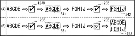
図6(A)を参照し、具体例を挙げて説明する。第1状態の電子ペン3によって、用紙123の記入領域123Aに「文字列ABCDE」が筆記される(図4、四角形541内参照)。この場合、CPU21は、文字列「ABCDE」に対応する複数の線分データを、RAM22の第2領域に記憶する。次いで、第1状態の電子ペン3によってチェックボックス123Bに線画が筆記される。この場合、CPU21は、RAM22の第2領域に記憶された複数の線分データを含むストロークデータを作成する。CPU21は、作成したストロークデータに基づいて、文字列「ABCDE」を含む四角形541で囲まれた領域を示す画像の画像ファイルを作成する。CPU21は、画像ファイル、ストロークデータ、及び作成日時を対応付け、ファイルリスト231(図5参照)に格納する。以下、ファイルリスト231に対応付けて記憶された画像ファイル、ストロークデータ、及び作成日時の単位を、登録ファイルという。CPU21は、文字列「ABCDE」に対応する登録ファイルをファイルリスト231に記憶した後、文字列「ABCDE」に対応する複数の線分データを、RAM22の第2領域から削除する。   A specific example will be described with reference to FIG. “Character string ABCDE” is written in the entry area 123A of the sheet 123 by the electronic pen 3 in the first state (see the inside of the rectangle 541 in FIG. 4). In this case, the CPU 21 stores a plurality of line segment data corresponding to the character string “ABCDE” in the second area of the RAM 22. Next, a line drawing is written in the check box 123B by the electronic pen 3 in the first state. In this case, the CPU 21 creates stroke data including a plurality of line segment data stored in the second area of the RAM 22. Based on the created stroke data, the CPU 21 creates an image file of an image showing an area surrounded by a rectangle 541 including the character string “ABCDE”. The CPU 21 associates the image file, the stroke data, and the creation date and time and stores them in the file list 231 (see FIG. 5). Hereinafter, the unit of the image file, the stroke data, and the creation date and time stored in association with the file list 231 is referred to as a registered file. After storing the registration file corresponding to the character string “ABCDE” in the file list 231, the CPU 21 deletes a plurality of line segment data corresponding to the character string “ABCDE” from the second area of the RAM 22.

更に、用紙123の記入領域123Aのうち、文字列「ABCDE」が筆記された部分の下側に、第1状態の電子ペン3によって文字列「FGHIJ」が筆記される(図4、四角形542内参照)。この場合、CPU21は、文字列「FGHIJ」に対応する複数の線分データを、RAM22の第2領域に記憶する。なお、文字列「ABCDE」に対応する複数の線分データは、RAM22の第2領域から削除されている。従って、文字列「FGHIJ」に対応する複数の線分データのみがRAM22の第2領域に記憶された状態になる。次いで、第1状態の電子ペン3によってチェックボックス123Bに線画が筆記される。この場合、CPU21は、RAM22の第2領域に記憶された複数の線分データを含むストロークデータを作成する。CPU21は、作成したストロークデータに基づいて、文字列「FGHIJ」を含む四角形542で囲まれた領域を示す画像の画像ファイルを作成する。CPU21は、画像ファイル、ストロークデータ、及び作成日時を対応付け、ファイルリスト231(図5参照)に格納する。   Further, the character string “FGHIJ” is written by the electronic pen 3 in the first state below the portion where the character string “ABCDE” is written in the entry area 123A of the sheet 123 (FIG. 4, inside the rectangle 542). reference). In this case, the CPU 21 stores a plurality of line segment data corresponding to the character string “FGHIJ” in the second area of the RAM 22. A plurality of line segment data corresponding to the character string “ABCDE” has been deleted from the second area of the RAM 22. Accordingly, only a plurality of line segment data corresponding to the character string “FGHIJ” is stored in the second area of the RAM 22. Next, a line drawing is written in the check box 123B by the electronic pen 3 in the first state. In this case, the CPU 21 creates stroke data including a plurality of line segment data stored in the second area of the RAM 22. Based on the created stroke data, the CPU 21 creates an image file of an image showing an area surrounded by a rectangle 542 including the character string “FGHIJ”. The CPU 21 associates the image file, the stroke data, and the creation date and time and stores them in the file list 231 (see FIG. 5).

更に、CPU21は、上記の処理に加え、RAM22の第1領域に記憶された線分データ及び状態データに基づいて、第2状態の電子ペン3によってチェックボックス123Bに線画を筆記する動作が行われたか判断する。CPU21は、第2状態の電子ペン3によってチェックボックス123Bに線画を筆記する動作が行われたと判断した場合、以下の処理を行う。   Further, in addition to the above processing, the CPU 21 performs an operation of writing a line drawing in the check box 123B by the electronic pen 3 in the second state based on the line segment data and the state data stored in the first area of the RAM 22. Judge. When the CPU 21 determines that the operation of writing a line drawing in the check box 123B is performed by the electronic pen 3 in the second state, the CPU 21 performs the following processing.

図6(B)を参照して説明する。第1状態の電子ペン3によって記入領域123Aに「文字列ABCDE」が筆記されてから(図4、四角形551内参照)、第1状態の電子ペン3によって文字列「FGHIJ」が筆記される(図4、四角形552内参照)までのCPU21の処理は、図6(A)の場合と同一であるので、説明を省略する。   This will be described with reference to FIG. The character string “ABCDE” is written in the entry area 123A by the electronic pen 3 in the first state (see the inside of the rectangle 551 in FIG. 4), and then the character string “FGHIJ” is written by the electronic pen 3 in the first state ( Since the processing of the CPU 21 up to FIG. 4 (see the rectangle 552) is the same as that in FIG. 6A, the description thereof is omitted.

次いで、第2状態の電子ペン3によって、チェックボックス123Bに線画を筆記する動作が行われる。なお、電子ペン3の芯体31は筒体30内に収容されているので、チェックボックス123Bに線画は筆記されない。この場合、CPU21は、ファイルリスト231のうち作成日時の最も新しい登録ファイルのストロークデータに含まれる複数の線分データを、RAM22の第2領域に記憶する。図6(B)の場合、第2状態の電子ペン3によってチェックボックス123Bに線画を筆記する動作が行われる直前に、第1状態の電子ペン3によって文字列「ABCDE」が筆記されている。従って、文字列「ABCDE」に対応する登録ファイルのストロークデータに含まれる複数の線分データが、RAM22の第2領域に記憶される。第2状態の電子ペン3によってチェックボックス123Bに線画を筆記する動作が行われることによって、文字列「ABCDE」に対応する線分データは、RAM22の第2領域から一旦削除された後、再度、RAM22の第2領域に記憶されることになる。なお、RAM22の第2領域には、文字列「FGHIJ」に対応する複数の線分データが記憶されている。従って、第2状態の電子ペン3によってチェックボックス123Bに線画を筆記する動作が行われたことによって、文字列「ABCDE」「FGHIJ」に対応する複数の線分データがRAM22の第2領域に記憶された状態になる。   Next, an operation of writing a line drawing in the check box 123B is performed by the electronic pen 3 in the second state. Since the core 31 of the electronic pen 3 is accommodated in the cylinder 30, no line drawing is written in the check box 123B. In this case, the CPU 21 stores a plurality of line segment data included in the stroke data of the registered file with the latest creation date and time in the file list 231 in the second area of the RAM 22. In the case of FIG. 6B, the character string “ABCDE” is written by the electronic pen 3 in the first state immediately before the operation of writing a line drawing in the check box 123B by the electronic pen 3 in the second state. Accordingly, a plurality of line segment data included in the stroke data of the registration file corresponding to the character string “ABCDE” is stored in the second area of the RAM 22. By performing an operation of writing a line drawing in the check box 123B by the electronic pen 3 in the second state, the line segment data corresponding to the character string “ABCDE” is once deleted from the second area of the RAM 22, and then again. It is stored in the second area of the RAM 22. A plurality of line segment data corresponding to the character string “FGHIJ” is stored in the second area of the RAM 22. Accordingly, when the electronic pen 3 in the second state performs an operation of writing a line drawing in the check box 123B, a plurality of line segment data corresponding to the character strings “ABCDE” and “FGHIJ” are stored in the second area of the RAM 22. It will be in the state.

次いで、CPU21は、RAM22の第2領域に記憶された複数の線分データを含むストロークデータを作成する。CPU21は、作成したストロークデータに基づいて、文字列「ABCDE」「FGHIJ」を含む四角形552で囲まれた領域を示す画像の画像ファイルを作成する。CPU21は、作成した画像ファイルに、文字列「ABCDE」「FGHIJ」に対応するストロークデータ及び作成日時を対応付け、文字列「ABCDE」に対応する登録ファイルに上書きしてファイルリスト231に格納する。CPU21は、画像ファイル、ストロークデータ、及び作成日時をファイルリスト231に記憶した後、文字列「ABCDE」「FGHIJ」に対応する複数の線分データを、RAM22の第2領域から削除する。   Next, the CPU 21 creates stroke data including a plurality of line segment data stored in the second area of the RAM 22. Based on the created stroke data, the CPU 21 creates an image file of an image indicating an area surrounded by a rectangle 552 including the character strings “ABCDE” and “FGHIJ”. The CPU 21 associates the created image file with the stroke data corresponding to the character strings “ABCDE” and “FGHIJ” and the creation date and time, overwrites the registration file corresponding to the character string “ABCDE”, and stores it in the file list 231. The CPU 21 stores the image file, stroke data, and creation date / time in the file list 231, and then deletes a plurality of line segment data corresponding to the character strings “ABCDE” and “FGHIJ” from the second area of the RAM 22.

以上のように、CPU21は、第2状態の電子ペン3によってチェックボックス123Bに線画を筆記する動作が行われたことに応じて、文字列「ABCDE」に対応する複数の線分データを、RAM22の第2領域に記憶する。CPU21は、RAM22の第2領域に記憶された複数の線分データに基づいて、ストロークデータ及び画像ファイルを再度作成する。従って、第2状態の電子ペン3によってチェックボックス123Bに線画を筆記する動作が行われたときに、RAM22の第2領域に別の文字列「FGHIJ」に対応する複数の線分データが記憶されている場合、CPU21は、文字列「ABCDE」と文字列「FGHIJ」とのストロークデータ及び画像ファイルを新たに作成できる。これによってファイルリスト231には、文字列「ABCDE」「FGHIJ」のストロークデータ及び画像ファイルが、文字列「ABCDE」のストロークデータ及び画像ファイルに代わって格納される。第2状態の電子ペン3を使用してチェックボックス123Bに線画を筆記する動作を行うことは、一旦作成されたストロークデータ及び画像ファイルに対応する文字列に、別の文字列を追記させ、ストロークデータ画像ファイルを新たに作成させるためにユーザが読取装置2に対して行う指示に相当する。   As described above, the CPU 21 stores a plurality of line segment data corresponding to the character string “ABCDE” in the RAM 22 in response to the operation of writing the line drawing in the check box 123B by the electronic pen 3 in the second state. Is stored in the second area. The CPU 21 creates stroke data and an image file again based on the plurality of line segment data stored in the second area of the RAM 22. Accordingly, when an operation of writing a line drawing in the check box 123B by the electronic pen 3 in the second state is performed, a plurality of line segment data corresponding to another character string “FGHIJ” is stored in the second area of the RAM 22. In this case, the CPU 21 can newly create stroke data and an image file of the character string “ABCDE” and the character string “FGHIJ”. Thus, the stroke data and image file of the character strings “ABCDE” and “FGHIJ” are stored in the file list 231 instead of the stroke data and the image file of the character string “ABCDE”. Using the electronic pen 3 in the second state to perform the operation of writing a line drawing in the check box 123B causes another character string to be added to the character string corresponding to the stroke data and the image file once created. This corresponds to an instruction given to the reading device 2 by the user in order to create a new data image file.

なお上記において、CPU21は、文字列「ABCDE」「FGHIJ」を含む画像の画像ファイルを別の方法で作成してもよい。例えばCPU21は、RAM22の第2領域に記憶された複数の線分データに基づいて、文字列「ABCDE」を示す線画と、文字列「FGHIJ」を示す線画を別々に作成してもよい。次にCPU21は、別々に作成した線画を上下方向に並べて配置させ、周囲を囲む四角形を特定してもよい。CPU21は、特定した四角形で囲まれた領域のみを含む画像の画像ファイルを作成してもよい。   In the above, the CPU 21 may create an image file of an image including the character strings “ABCDE” and “FGHIJ” by another method. For example, the CPU 21 may separately create a line drawing indicating the character string “ABCDE” and a line drawing indicating the character string “FGHIJ” based on a plurality of line segment data stored in the second area of the RAM 22. Next, the CPU 21 may specify the quadrangle surrounding the periphery by arranging line drawings created separately in the vertical direction. The CPU 21 may create an image file of an image including only the area surrounded by the specified rectangle.

図7を参照し、読取装置2のCPU21によって実行されるメイン処理を説明する。CPU21は、電源がONされた場合に、フラッシュROM23に記憶されたプログラムに基づいて動作することで、メイン処理を開始する。   A main process executed by the CPU 21 of the reading device 2 will be described with reference to FIG. When the power is turned on, the CPU 21 starts the main process by operating based on the program stored in the flash ROM 23.

はじめにCPU21は、次の初期化処理を実行する(S10)。CPU21は、RAM22に記憶されたデータをクリアする。CPU21は、ASIC28A,29Aの制御を開始する。これによってCPU21は、読取装置2に装着された紙媒体100の用紙111に電子ペン3を用いて線画が筆記されているか否かを判断できる状態になる。又、CPU21は、電子ペン3を用いて線画が筆記されている状態であると判断した場合に、電子ペン3の位置を示す座標データを取得できる状態になる。更に、CPU21は、電子ペン3の状態を判断できる状態になる。   First, the CPU 21 executes the following initialization process (S10). The CPU 21 clears the data stored in the RAM 22. The CPU 21 starts control of the ASICs 28A and 29A. As a result, the CPU 21 can determine whether or not a line drawing is written on the paper 111 of the paper medium 100 attached to the reading device 2 using the electronic pen 3. In addition, when the CPU 21 determines that the line drawing is being written using the electronic pen 3, the CPU 21 can acquire coordinate data indicating the position of the electronic pen 3. Furthermore, the CPU 21 can determine the state of the electronic pen 3.

CPU21は、読取装置2に装着された紙媒体100の用紙111のフォーマットを特定する(S11)。具体的には、CPU21は次のようにしてフォーマットを特定する。CPU21は、用紙111のフォーマットが特定されていないことをユーザに通知するために、赤色のLED5を点灯させる。ユーザは、用紙111の隅に印刷された図示外の複数のキャリブレーションマークの位置に、用紙111のフォーマットに対応する順番で電子ペン3によって線画を筆記する。CPU21は、線画を筆記する動作が行われた位置を示す複数の座標データを順番に取得し、線画が筆記された位置、及び、線画が筆記された順番を特定する。CPU21は、特定した位置及び順番に対応する用紙111のフォーマットを特定する。なお、キャリブレーションマークの位置に筆記する動作が行われる場合の電子ペン3の状態は、第1状態であってもよいし、第2状態であってもよい。   The CPU 21 specifies the format of the paper 111 of the paper medium 100 loaded in the reading device 2 (S11). Specifically, the CPU 21 specifies the format as follows. The CPU 21 turns on the red LED 5 to notify the user that the format of the paper 111 is not specified. The user writes line drawings with the electronic pen 3 at the positions of a plurality of calibration marks (not shown) printed at the corners of the paper 111 in the order corresponding to the format of the paper 111. The CPU 21 sequentially acquires a plurality of coordinate data indicating the position where the operation of writing the line drawing is performed, and specifies the position where the line drawing is written and the order in which the line drawing is written. The CPU 21 specifies the format of the paper 111 corresponding to the specified position and order. Note that the state of the electronic pen 3 when the operation of writing at the position of the calibration mark is performed may be the first state or the second state.

CPU21は、特定された用紙111のフォーマットを示すフォーマット情報をRAM22に記憶する(S11)。CPU21は、用紙111のフォーマットが特定されたことをユーザに通知するために、緑色のLED5を点灯させる。以下、用紙123(図4参照)が読取装置2に装着され、用紙123のフォーマットが特定された場合を例に挙げて具体的に説明する。   The CPU 21 stores format information indicating the format of the specified paper 111 in the RAM 22 (S11). The CPU 21 turns on the green LED 5 to notify the user that the format of the paper 111 has been specified. Hereinafter, the case where the sheet 123 (see FIG. 4) is loaded in the reading device 2 and the format of the sheet 123 is specified will be specifically described as an example.

CPU21は、特定したフォーマットに対応する情報であって、用紙123の記入領域123A及びチェックボックス123Bの夫々の位置を特定することが可能なデータ(以下、レイアウトデータという。)を、フラッシュROM23から読み出してRAM22に記憶する(S12)。CPU21は、用紙123が装着される領域、即ち読取装置2の前面のうち、チェックボックス123Bに対応する領域を、S12でRAM22に記憶したレイアウトデータに基づいて特定する。以下、チェックボックス123Bを構成する矩形状の領域に対応する読取装置2の前面の領域を、チェック領域という。   The CPU 21 reads information (hereinafter referred to as layout data) from the flash ROM 23 that is information corresponding to the specified format and can specify the positions of the entry area 123A and the check box 123B of the sheet 123. Is stored in the RAM 22 (S12). The CPU 21 specifies an area corresponding to the check box 123B in the area where the sheet 123 is mounted, that is, the front surface of the reading device 2, based on the layout data stored in the RAM 22 in S12. Hereinafter, the area on the front surface of the reading device 2 corresponding to the rectangular area constituting the check box 123B is referred to as a check area.

CPU21は、入力部25に対する入力操作を検出したか判断する(S13)。CPU21は、入力部25に対する入力操作を検出したと判断した場合(S13:YES)、検出した入力操作に対応する処理の内容を特定する。処理の内容の具体例は、異常発生時のリスタート処理、用紙111のフォーマットを再度特定する処理等である。CPU21は、特定した処理の内容に基づいて処理を実行する(S15)。CPU21は、処理をS13に戻す。   CPU21 judges whether the input operation with respect to the input part 25 was detected (S13). When the CPU 21 determines that an input operation on the input unit 25 has been detected (S13: YES), the CPU 21 specifies the content of the process corresponding to the detected input operation. Specific examples of the contents of the process include a restart process when an abnormality occurs, a process of specifying the format of the paper 111 again, and the like. CPU21 performs a process based on the content of the specified process (S15). CPU21 returns a process to S13.

CPU21は、入力部25に対する入力操作を検出しないと判断した場合(S13:NO)、電子ペン3に付与された筆圧を特定し、第1状態又は第2状態の電子ペン3によって用紙123に線画を筆記する動作が行われているかを判断する(S17)。CPU21は、用紙123に線画を筆記する動作が行われていると判断した場合(S17:YES)、座標データを取得する。CPU21は、更に、取得された座標データが検出された時刻を示す時間データを取得する。CPU21は、取得した座標データ及び時間データを関連付け、RAM22の第1領域に記憶する。CPU21は、電子ペン3による1つの線分の筆記が終了するまで、取得した座標データ及び時間データをRAM22の第1領域に記憶する処理を繰り返す。電子ペン3による線分の筆記が終了した場合、1つの線分に対応する複数の座標データ及び複数の時間データが線分データとしてRAM22の第1領域に記憶された状態になる(S23)。更に、CPU21は、電子ペン3の状態(第1状態又は第2状態)を特定し、RAM22の第1領域に状態データを記憶する。   When the CPU 21 determines that the input operation to the input unit 25 is not detected (S13: NO), the CPU 21 specifies the writing pressure applied to the electronic pen 3 and applies it to the paper 123 by the electronic pen 3 in the first state or the second state. It is determined whether an operation of writing a line drawing is being performed (S17). When the CPU 21 determines that an operation of writing a line drawing on the paper 123 is performed (S17: YES), the CPU 21 acquires coordinate data. The CPU 21 further acquires time data indicating the time when the acquired coordinate data is detected. The CPU 21 associates the acquired coordinate data and time data and stores them in the first area of the RAM 22. The CPU 21 repeats the process of storing the acquired coordinate data and time data in the first area of the RAM 22 until the writing of one line segment by the electronic pen 3 is completed. When writing of the line segment by the electronic pen 3 is completed, a plurality of coordinate data and a plurality of time data corresponding to one line segment are stored in the first area of the RAM 22 as line segment data (S23). Further, the CPU 21 specifies the state (first state or second state) of the electronic pen 3 and stores the state data in the first area of the RAM 22.

CPU21は、チェックボックス123Bに線画を筆記する動作が行われたかを、S23で取得した線分データに基づいて判断する(S25)。具体的には、CPU21は、取得した線分データの複数の座標データの少なくとも1つが、チェック領域内の位置を示している場合、チェックボックス123Bに線画を筆記する動作が行われたと判断する(S25:YES)。一方、CPU21は、複数の座標データの全てが、チェック領域外の位置を示している場合、チェックボックス123Bに線画を筆記する動作が行われていないと判断する(S25:NO)。   The CPU 21 determines whether an operation of writing a line drawing in the check box 123B has been performed based on the line segment data acquired in S23 (S25). Specifically, the CPU 21 determines that an operation of writing a line drawing in the check box 123B has been performed when at least one of the plurality of coordinate data of the acquired line segment data indicates a position in the check area ( S25: YES). On the other hand, when all of the plurality of coordinate data indicate positions outside the check area, the CPU 21 determines that the operation of writing a line drawing in the check box 123B is not performed (S25: NO).

CPU21は、チェックボックス123Bに線画を筆記する動作が行われていないと判断した場合(S25:NO)、記入領域123Aに線画を筆記する動作が行われたと判断する。CPU21は、RAM22の第1領域に記憶された状態データに基づいて、電子ペン3の状態が第1状態であるかを判断する(S26)。電子ペン3の状態が第1状態である場合、芯体31は筒体30から突出しているので、記入領域123Aに電子ペン3で線画が筆記されている。CPU21は、電子ペン3の状態が第1状態であると判断した場合(S26:YES)、RAM22の第1領域に記憶された線分データ及び状態データを、RAM22の第2領域に記憶する(S27)。CPU21は、RAM22の第1領域をクリアし、処理をS13に戻す。一方、電子ペン3の状態が第2状態である場合、芯体31は筒体30内に収容されているので、記入領域123Aに線画は筆記されていない。CPU21は、電子ペン3の状態が第2状態であると判断した場合(S26:NO)、処理をS13に戻す。   When the CPU 21 determines that an operation for writing a line drawing in the check box 123B is not performed (S25: NO), the CPU 21 determines that an operation for writing a line drawing in the entry area 123A is performed. The CPU 21 determines whether the state of the electronic pen 3 is the first state based on the state data stored in the first area of the RAM 22 (S26). When the state of the electronic pen 3 is the first state, the core body 31 protrudes from the cylindrical body 30, and therefore a line drawing is written with the electronic pen 3 in the entry area 123A. When the CPU 21 determines that the state of the electronic pen 3 is the first state (S26: YES), it stores the line segment data and the state data stored in the first area of the RAM 22 in the second area of the RAM 22 ( S27). The CPU 21 clears the first area of the RAM 22 and returns the process to S13. On the other hand, when the state of the electronic pen 3 is the second state, the core body 31 is accommodated in the cylindrical body 30, and therefore no line drawing is written in the entry area 123A. CPU21 returns a process to S13, when it is judged that the state of the electronic pen 3 is a 2nd state (S26: NO).

CPU21は、チェックボックス123Bに線画を筆記する動作が行われたと判断した場合(S25:YES)、少なくとも1つの線分データがRAM22の第2領域に記憶されているかを判断する(S28)。CPU21は、RAM22の第2領域に線分データが記憶されていないと判断した場合(S28:NO)、処理をS13に戻す。一方、CPU21は、少なくとも1つの線分データがRAM22の第2領域に記憶されていると判断した場合(S28:YES)、RAM22の第2領域に記憶された状態データに基づいて、電子ペン3の状態が第1状態であるかを判断する(S29)。CPU21は、電子ペン3の状態が第1状態であると判断した場合(S29:YES)、RAM22の第2領域に記憶された少なくとも1つの線分データを含むストロークデータを作成する(S31)。CPU21は、作成したストロークデータに含まれる少なくとも1つの線分データによって示される線画を示す画像の画像ファイルを作成する(S31)。CPU21は、ストロークデータ及び画像ファイルを作成した日時を特定する。CPU21は、画像ファイル、画像ファイルを作成するときに使用したストロークデータ、及び、特定した作成日時を対応付けて、ファイルリスト231に記憶する(S33)。CPU21は、作成したストロークデータに含まれる少なくとも1つの線分データを、RAM22の第2領域から削除する(S35)。CPU21は処理をS13に戻す。   When the CPU 21 determines that an operation of writing a line drawing in the check box 123B has been performed (S25: YES), the CPU 21 determines whether at least one line segment data is stored in the second area of the RAM 22 (S28). When the CPU 21 determines that the line segment data is not stored in the second area of the RAM 22 (S28: NO), the process returns to S13. On the other hand, when the CPU 21 determines that at least one line segment data is stored in the second area of the RAM 22 (S28: YES), the electronic pen 3 is based on the state data stored in the second area of the RAM 22. Whether the state is the first state is determined (S29). When determining that the state of the electronic pen 3 is the first state (S29: YES), the CPU 21 creates stroke data including at least one line segment data stored in the second area of the RAM 22 (S31). The CPU 21 creates an image file of an image showing a line drawing indicated by at least one line segment data included in the created stroke data (S31). The CPU 21 specifies the date and time when the stroke data and the image file are created. The CPU 21 stores the image file, the stroke data used when creating the image file, and the specified creation date and time in the file list 231 (S33). The CPU 21 deletes at least one line segment data included in the created stroke data from the second area of the RAM 22 (S35). The CPU 21 returns the process to S13.

例えば、図6(A)に示すように、第1状態の電子ペン3によって記入領域123Aに文字列「ABCDE」が筆記された場合(S25:NO)、RAM22の第2領域に、文字列「ABCDE」に対応する複数の線分データが記憶される(S27)。次いで、第1状態の電子ペン3によってチェックボックス123Bに線画を筆記する動作が行われた場合(S25:YES、S28:YES、S29:YES)、RAM22の第2領域に記憶された複数の線分データを含む文字列「ABCDE」のストロークデータが作成される(S31)。又、作成されたストロークデータに基づいて、文字列「ABCDE」を示す画像の画像ファイルが作成される(S31)。作成されたストロークデータ及び画像ファイルを含む登録ファイルは、ファイルリスト231に記憶される(S33)。登録ファイルがファイルリスト231に記憶された後、文字列「ABCDE」に対応する複数の線分データは、RAM22の第2領域から削除される(S35)。   For example, as shown in FIG. 6A, when the character string “ABCDE” is written in the entry area 123A by the electronic pen 3 in the first state (S25: NO), the character string “ABCDE” is written in the second area of the RAM 22. A plurality of line segment data corresponding to “ABCDE” is stored (S27). Next, when an operation of writing a line drawing in the check box 123B with the electronic pen 3 in the first state (S25: YES, S28: YES, S29: YES), a plurality of lines stored in the second area of the RAM 22 Stroke data of a character string “ABCDE” including minute data is created (S31). An image file of an image indicating the character string “ABCDE” is created based on the created stroke data (S31). The registration file including the created stroke data and image file is stored in the file list 231 (S33). After the registered file is stored in the file list 231, a plurality of line segment data corresponding to the character string “ABCDE” is deleted from the second area of the RAM 22 (S35).

一方、図7に示すように、電子ペン3の状態が第2状態であると判断した場合(S29:NO)、CPU21は、少なくとも1つの登録ファイルがファイルリスト231に記憶されているかを判断する(S39)。CPU21は、登録ファイルがファイルリスト231に記憶されていないと判断した場合(S39:NO)、処理をS13に戻す。CUP21は、少なくとも1つの登録ファイルがファイルリスト231に記憶されていると判断した場合(S39:YES)、作成日時の最も新しい登録ファイルをファイルリスト231から取得する(S41)。CPU21は、取得した登録ファイルのストロークデータに含まれている少なくとも1つの線分データを取得し、RAM22の第2領域に記憶する(S43)。なお、RAM22の第2領域に線分データが既に記憶されている場合には、S41の処理によって、登録ファイルのストロークデータに含まれている少なくとも1つの線分データに、RAM22の第2領域に記憶されていた線分データが追加され、RAM22の第2領域に記憶されることになる。   On the other hand, as shown in FIG. 7, when it is determined that the state of the electronic pen 3 is the second state (S29: NO), the CPU 21 determines whether at least one registered file is stored in the file list 231. (S39). If the CPU 21 determines that the registered file is not stored in the file list 231 (S39: NO), it returns the process to S13. If the CUP 21 determines that at least one registered file is stored in the file list 231 (S39: YES), the CUP 21 obtains the newest registered file from the file list 231 (S41). The CPU 21 acquires at least one line segment data included in the stroke data of the acquired registration file and stores it in the second area of the RAM 22 (S43). If line segment data is already stored in the second area of the RAM 22, at least one line segment data included in the stroke data of the registration file is converted into the second area of the RAM 22 by the process of S41. The stored line segment data is added and stored in the second area of the RAM 22.

CPU21は、RAM22の第2領域に記憶された少なくとも1つの線分データを含むストロークデータを作成する(S45)。CPU21は、作成したストロークデータに含まれる少なくとも1つの線分データによって示される線画を示す画像の画像ファイルを作成する(S45)。CPU21は、作成した画像ファイルを作成した日時を特定する。CPU21は、作成した画像ファイル、画像ファイルを作成するときに使用したストロークデータ、及び、特定した作成日時を対応付け、S41の処理によって取得された登録ファイルに上書きして記憶する(S47)。これによって、S41の処理によって取得された登録ファイルは、ファイルリスト231から削除される。CPU21は、作成したストロークデータに含まれる少なくとも1つの線分データを、RAM22の第2領域から削除する(S49)。   The CPU 21 creates stroke data including at least one line segment data stored in the second area of the RAM 22 (S45). The CPU 21 creates an image file of an image showing a line drawing indicated by at least one line segment data included in the created stroke data (S45). The CPU 21 specifies the date and time when the created image file was created. The CPU 21 associates the created image file, the stroke data used when creating the image file, and the specified creation date and time, and overwrites and stores the registration file acquired by the process of S41 (S47). As a result, the registered file acquired by the process of S41 is deleted from the file list 231. The CPU 21 deletes at least one line segment data included in the created stroke data from the second area of the RAM 22 (S49).

例えば、図6(B)に示すように、第1状態の電子ペン3によって記入領域123Aに文字列「ABCDE」が筆記された後、第1状態の電子ペン3によってチェックボックス123Bに線画を筆記する動作が行われた場合、文字列「ABCDE」のストロークデータ及び画像ファイルが作成され、ファイルリスト231に記憶される。文字列「ABCDE」に対応する複数の線分データは、RAM22の第2領域から削除される。次いで、第1状態の電子ペン3によって記入領域123Aに文字列「FGHIJ」が筆記された場合、文字列「FGHIJ」に対応する複数の線分データが取得され、RAM22の第2領域に記憶される(S23)。なお、文字列「ABCDE」に対応する複数の線分データはRAM22の第2領域から削除されているので、文字列「FGHIJ」に対応する複数の線分データのみがRAM22の第2領域に記憶された状態になる。   For example, as shown in FIG. 6B, after the character string “ABCDE” is written in the entry area 123A by the electronic pen 3 in the first state, a line drawing is written in the check box 123B by the electronic pen 3 in the first state. When the operation is performed, stroke data and an image file of the character string “ABCDE” are created and stored in the file list 231. A plurality of line segment data corresponding to the character string “ABCDE” is deleted from the second area of the RAM 22. Next, when the character string “FGHIJ” is written in the entry area 123A by the electronic pen 3 in the first state, a plurality of line segment data corresponding to the character string “FGHIJ” is acquired and stored in the second area of the RAM 22. (S23). Since a plurality of line segment data corresponding to the character string “ABCDE” is deleted from the second area of the RAM 22, only a plurality of line segment data corresponding to the character string “FGHIJ” is stored in the second area of the RAM 22. It will be in the state.

次いで、第2状態の電子ペン3によってチェックボックス123Bに線画を筆記する動作が行われた場合(S25:YES、S28:YES、S29:NO)、文字列「ABCDE」に対応する登録ファイルが取得される(S41)。取得された登録ファイルのストロークデータに含まれる複数の線分データは、RAM22の第2領域に記憶される(S43)。RAM22の第2領域は、文字列「ABCDE」「FGHIJ」に対応する複数の線分データが記憶された状態になる。従って、RAM22の第2領域に記憶された複数の線分データに基づいてストロークデータが作成され(S45)、画像ファイルが作成された場合(S45)、作成された画像ファイルの画像には、文字列「ABCDE」「FGHIJ」が含まれる。   Next, when the electronic pen 3 in the second state performs an operation of writing a line drawing on the check box 123B (S25: YES, S28: YES, S29: NO), a registration file corresponding to the character string “ABCDE” is acquired. (S41). A plurality of line segment data included in the stroke data of the acquired registration file is stored in the second area of the RAM 22 (S43). The second area of the RAM 22 is in a state in which a plurality of line segment data corresponding to the character strings “ABCDE” and “FGHIJ” are stored. Accordingly, when stroke data is created based on a plurality of line segment data stored in the second area of the RAM 22 (S45) and an image file is created (S45), the image of the created image file contains characters. The columns “ABCDE” and “FGHIJ” are included.

CPU21は、S17の処理において、用紙123に線画が筆記されていない状態であると判断した場合(S17:NO)、スマートフォン19から無線送信されたデータ要求コマンドを、無線通信部24を介して受信したか判断する(S19)。CPU21は、データ要求コマンドを受信していないと判断した場合(S19:NO)、処理をS13に戻す。CPU21は、データ要求コマンドを受信したと判断した場合(S19:YES)、S33でファイルリスト231に記憶した画像ファイルを、無線通信部24を介してスマートフォン19に無線送信する(S21)。CPU21は処理をS13に戻す。   When the CPU 21 determines in the process of S17 that the line drawing is not written on the sheet 123 (S17: NO), the CPU 21 receives the data request command wirelessly transmitted from the smartphone 19 via the wireless communication unit 24. It is determined whether or not (S19). When determining that the data request command has not been received (S19: NO), the CPU 21 returns the process to S13. When the CPU 21 determines that the data request command has been received (S19: YES), the CPU 21 wirelessly transmits the image file stored in the file list 231 to the smartphone 19 via the wireless communication unit 24 (S21). The CPU 21 returns the process to S13.

なお、スマートフォン19のCPU41は、読取装置2から画像ファイルを取得するための操作がタッチパネル191を介して行われた場合、無線通信部44を介して読取装置2との間で近距離無線通信を実行し、読取装置2に対してデータ要求コマンドを送信する。読取装置2のフラッシュROM23のファイルリスト231に格納された画像ファイルは、読取装置2からスマートフォン19に無線送信される。CPU41は、読取装置2から無線送信された画像ファイルを受信し、フラッシュROM43に記憶する。CPU41は、フラッシュROM43に記憶した画像ファイルに基づいて、電子ペン3によって用紙123に筆記された線画と同一形状の線画を含む画像をディスプレイ192に表示させる。なお、読取装置2からスマートフォン19に対して画像ファイルが送信される場合の通信は、無線通信に限定されず有線通信であってもよい。   Note that the CPU 41 of the smartphone 19 performs short-range wireless communication with the reading device 2 via the wireless communication unit 44 when an operation for acquiring an image file from the reading device 2 is performed via the touch panel 191. The data request command is transmitted to the reading device 2. The image file stored in the file list 231 of the flash ROM 23 of the reading device 2 is wirelessly transmitted from the reading device 2 to the smartphone 19. The CPU 41 receives the image file wirelessly transmitted from the reading device 2 and stores it in the flash ROM 43. Based on the image file stored in the flash ROM 43, the CPU 41 causes the display 192 to display an image including a line drawing having the same shape as the line drawing written on the paper 123 by the electronic pen 3. Note that the communication when the image file is transmitted from the reading device 2 to the smartphone 19 is not limited to wireless communication, and may be wired communication.

以上説明したように、読取装置2のCPU21は、第1状態の電子ペン3によってチェックボックス123Bに線画を筆記する動作が行われたと判断した場合(S29:YES)、RAM22の第2領域に記憶された少なくとも1つの線分データに対応する線画のストロークデータ及び画像ファイルを作成し(S31)、ファイルリスト231に格納する(S33)。これによってCPU21は、第1状態の電子ペン3によって用紙123に筆記された線画のストロークデータ及び画像ファイルをファイルリスト231に格納できる。   As described above, when the CPU 21 of the reading device 2 determines that an operation of writing a line drawing on the check box 123B is performed by the electronic pen 3 in the first state (S29: YES), the CPU 21 stores it in the second area of the RAM 22. Line drawing stroke data and an image file corresponding to the at least one line segment data are created (S31) and stored in the file list 231 (S33). Thus, the CPU 21 can store the stroke data and the image file of the line drawing written on the paper 123 with the electronic pen 3 in the first state in the file list 231.

一方、CPU21は、第2状態の電子ペン3によってチェックボックス123Bに線画を筆記する動作が行われたと判断した場合(S29:NO)、ファイルリスト231に格納されたストロークデータ及び画像ファイルに対応する線画と、RAM22の第2領域に記憶された線分データに対応する線画との両方のストロークデータ、及び画像ファイルを作成し(S31)、ファイルリスト231に格納する(S33)。これによってCPU21は、電子ペン3によって先に筆記された線画と後で筆記された線画との両方のストロークデータ、及び画像ファイルを作成できる。従ってユーザは、第2状態とした電子ペン3によってチェックボックス123Bに線画を筆記する動作を行うことによって、記入領域123Aに先に筆記した線画と後で筆記した線画との両方のストロークデータ、及び画像ファイルを、読取装置2に作成させることができる。このためユーザは、図6(B)に示すように、文字列「ABCDE」のストロークデータ及び画像ファイルが一旦作成された後でも、文字列「ABCDE」と、追記された文字列「FGHIJ」との両方のストロークデータ及び画像ファイルを、読取装置2に容易に作成させることができる。   On the other hand, if the CPU 21 determines that the operation of writing a line drawing in the check box 123B with the electronic pen 3 in the second state (S29: NO), the CPU 21 corresponds to the stroke data and the image file stored in the file list 231. Stroke data and an image file of both the line drawing and the line drawing corresponding to the line segment data stored in the second area of the RAM 22 are created (S31) and stored in the file list 231 (S33). As a result, the CPU 21 can create stroke data and an image file of both the line drawing previously written by the electronic pen 3 and the line drawing written later. Therefore, the user performs an operation of writing a line drawing in the check box 123B with the electronic pen 3 set in the second state, so that stroke data of both the line drawing previously written in the entry area 123A and the line drawing written later, and An image file can be created in the reading device 2. For this reason, as shown in FIG. 6B, the user can create the character string “ABCDE” and the added character string “FGHIJ” even after the stroke data and image file of the character string “ABCDE” are once created. Both of the stroke data and the image file can be easily created by the reading device 2.

第1状態の電子ペン3によってチェックボックス123Bに筆記する動作が行われた場合、電子ペン3は筆記可能な状態であるので、チェックボックス123Bに線画が筆記される。一方、第2状態の電子ペン3によってチェックボックス123Bに筆記する動作が行われた場合、電子ペン3は筆記不可能な状態であるので、チェックボックス123Bに線画は筆記されない。チェックボックス123Bに筆記が頻繁に行われた場合、直近に筆記した線画を認識し難くなるので、第1状態の電子ペン3で筆記したか、第2状態の電子ペン3で筆記したかを区別し難くなる。これに対し、読取装置2では、チェックボックス123Bに対する筆記が頻繁に行われることを抑制できる。従ってユーザは、直近に筆記した線画を認識し易くなるので、第1状態の電子ペン3で筆記したか、第2状態の電子ペン3で筆記したかを区別し易くなる。   When an operation of writing in the check box 123B is performed with the electronic pen 3 in the first state, the electronic pen 3 is in a state where writing is possible, and thus a line drawing is written in the check box 123B. On the other hand, when the writing operation is performed on the check box 123B by the electronic pen 3 in the second state, the electronic pen 3 is in a state in which writing is not possible, and therefore no line drawing is written on the check box 123B. If writing is frequently performed in the check box 123B, it becomes difficult to recognize the most recently drawn line drawing, so it is distinguished whether writing was performed with the electronic pen 3 in the first state or the electronic pen 3 in the second state. It becomes difficult to do. On the other hand, the reading device 2 can suppress frequent writing to the check box 123B. Therefore, the user can easily recognize the line drawing written most recently, so that it is easy to distinguish between writing with the electronic pen 3 in the first state or writing with the electronic pen 3 in the second state.

なお、ストロークデータ及び画像ファイルの作成を指示するために第1状態の電子ペン3で筆記する領域と、線画が追加されたストロークデータ及び画像ファイルの作成を指示するために第2状態の電子ペン3で筆記する領域とは、何れもチェックボックス123Bである。このため、用紙123にチェックボックス123Bを複数設ける必要がない。従って読取装置2は、複数のチェックボックスが設けられることによって記入領域123Aが狭くなることを軽減できる。又、ユーザは、電子ペン3の状態を切り替え、共通のチェックボックス123Bに線画を筆記する動作を行うことによって、読取装置2に異なる動作を指示できる。従ってユーザは、複数のチェックボックスを使い分ける必要がないので、読取装置2に対して異なる動作を容易に指示できる。   An area to be written with the electronic pen 3 in the first state in order to instruct creation of stroke data and an image file, and an electronic pen in the second state in order to instruct creation of stroke data and an image file to which line drawings have been added. The area to be written in 3 is a check box 123B. For this reason, it is not necessary to provide a plurality of check boxes 123B on the sheet 123. Therefore, the reading device 2 can reduce the entry area 123A from being narrowed by providing a plurality of check boxes. Further, the user can instruct the reading device 2 to perform different operations by switching the state of the electronic pen 3 and performing an operation of writing a line drawing in the common check box 123B. Therefore, the user does not need to use a plurality of check boxes separately, and can easily instruct the reader 2 to perform different operations.

電子ペン3は、共振周波数の異なる第1共振回路38A(共振周波数:第1周波数)及び第2共振回路38B(共振周波数:第2周波数)を有する。電子ペン3は、用紙111に対する筆記が可能な状態(第1状態)で第1共振回路38Aを有効とし、用紙111に対する筆記が不可能な状態(第2状態)で第2共振回路38Bを有効とすることができる。従ってCPU21は、第1周波数の電流をループコイルに流したことに応じて誘導電流を検出した場合、電子ペン3が第1状態であると判断し、第2周波数の電流をループコイルに流したことに応じて誘導電流を検出した場合、電子ペン3が第2状態であると判断できる。このように、CPU21は、検出される誘導電流に応じて、電子ペン3の状態を容易に判断できる。   The electronic pen 3 includes a first resonance circuit 38A (resonance frequency: first frequency) and a second resonance circuit 38B (resonance frequency: second frequency) having different resonance frequencies. The electronic pen 3 enables the first resonance circuit 38A when writing on the paper 111 (first state) is enabled, and enables the second resonance circuit 38B when writing on the paper 111 is not possible (second state). It can be. Therefore, the CPU 21 determines that the electronic pen 3 is in the first state when the induced current is detected in response to flowing the current of the first frequency through the loop coil, and flows the current of the second frequency through the loop coil. If the induced current is detected accordingly, it can be determined that the electronic pen 3 is in the second state. As described above, the CPU 21 can easily determine the state of the electronic pen 3 according to the detected induced current.

CPU21は、第2状態の電子ペン3によってチェックボックス123Bに筆記する動作を行った場合、最も新しい作成日時の登録ファイルをファイルリスト231から取得し(S41)、ストロークデータに含まれる線分データをRAM22の第2領域に記憶する(S43)。ここで、RAM22の第2領域に別の線分データが追加して記憶されている場合、S43で記憶された線分データに対応する線画と、RAM22の第2領域に追加して記憶された線分データに対応する線画とのストロークデータ及び画像ファイルが作成される(S31)。このように、RAM22の第2領域に追加して記憶された線分データに対応する線画と共に画像に含められる線画は、常に、最も新しい作成日時の登録ファイルのストロークデータに含まれる線分データに対応する線画になる。ユーザは、追記の対象とする線画のストロークデータ及び画像ファイルを、複数のストロークデータ及び複数の画像ファイルから選択する必要がない。このため、ユーザは、先に筆記された線画と後で筆記された線画のストロークデータ及び画像ファイルを読取装置2に作成させる場合の操作を容易に行うことができる。   When the CPU 21 performs an operation of writing in the check box 123B with the electronic pen 3 in the second state, the CPU 21 obtains the registration file having the latest creation date from the file list 231 (S41), and extracts the line segment data included in the stroke data. Store in the second area of the RAM 22 (S43). Here, when another line segment data is additionally stored in the second area of the RAM 22, the line drawing corresponding to the line segment data stored in S43 and the second area of the RAM 22 are additionally stored. Stroke data and an image file with a line drawing corresponding to the line segment data are created (S31). As described above, the line drawing included in the image together with the line drawing corresponding to the line segment data stored in addition to the second area of the RAM 22 is always the line segment data included in the stroke data of the registration file of the latest creation date and time. It becomes the corresponding line drawing. The user does not need to select the stroke data and image file of the line drawing to be added from the plurality of stroke data and the plurality of image files. For this reason, the user can easily perform an operation when the reading device 2 creates stroke data and an image file of a line drawing written earlier and a line drawing written later.

本発明は上記実施形態に限定されず、種々の変更が可能である。上記のメイン処理の一部は、スマートフォン19のCPU41によって実行されてもよい。例えば、上記実施形態では、読取装置2のCPU21によって画像ファイルが作成され、スマートフォン19からの要求に応じて、作成された画像ファイルがスマートフォン19に送信された。これに対し、画像ファイルは、スマートフォン19のCPU41によって作成されてもよい。例えばCPU21は、第1状態の電子ペン3によって、チェックボックス123Bに線画を筆記する動作が行われた場合(S25:YES、S29:YES)、S31の処理において、画像ファイルを作成せずストロークデータのみ作成し、ファイルリスト231に記憶してもよい(S33)。CPU21は、スマートフォン19から無線送信されたデータ要求コマンドを受信した場合(S19:YES)、S21の処理において、ファイルリスト231に記憶したストロークデータをスマートフォン19に送信してもよい。スマートフォン19のCPU41は、読取装置2からストロークデータを受信した場合、受信したストロークデータに基づいて画像ファイルを作成してもよい。CPU41は、作成した画像ファイルに基づいて、電子ペン3によって用紙123に筆記された線画と同一形状の線画を含む画像をディスプレイ192に表示させてもよい。   The present invention is not limited to the above embodiment, and various modifications can be made. A part of the main process may be executed by the CPU 41 of the smartphone 19. For example, in the above embodiment, an image file is created by the CPU 21 of the reading device 2, and the created image file is transmitted to the smartphone 19 in response to a request from the smartphone 19. On the other hand, the image file may be created by the CPU 41 of the smartphone 19. For example, when the electronic pen 3 in the first state performs an operation of writing a line drawing in the check box 123B (S25: YES, S29: YES), the CPU 21 does not create an image file and does not create an image file in the process of S31. May be created and stored in the file list 231 (S33). When the data request command wirelessly transmitted from the smartphone 19 is received (S19: YES), the CPU 21 may transmit the stroke data stored in the file list 231 to the smartphone 19 in the process of S21. When receiving the stroke data from the reading device 2, the CPU 41 of the smartphone 19 may create an image file based on the received stroke data. The CPU 41 may cause the display 192 to display an image including a line drawing having the same shape as the line drawing written on the paper 123 by the electronic pen 3 based on the created image file.

チェックボックス123Bは用紙123に設けられていなくてもよい。CPU21は、S23で取得した線分データに対応する複数の座標データによって示される位置が所定の条件を満たす場合(例えば、用紙123の四隅の何れかの位置に筆記する動作が行われた場合)、ストロークデータ及び画像ファイルの作成処理(S31)を実行してもよい。又、CPU21は、S23で取得した線分データに対応する線分の形状が所定の条件を満たす場合に、ストロークデータ及び画像ファイルの作成処理(S31)を実行してもよい。又、CPU21は、電子ペン3が用紙123の特定の位置に押し付けられた状態の継続時間が所定時間よりも長い場合に、ストロークデータ及び画像ファイルの作成処理(S31)を実行してもよい。   The check box 123B may not be provided on the sheet 123. When the position indicated by the plurality of coordinate data corresponding to the line segment data acquired in S23 satisfies the predetermined condition (for example, when the writing operation is performed at any one of the four corners of the paper 123), the CPU 21 The stroke data and image file creation process (S31) may be executed. Further, the CPU 21 may execute the stroke data and image file creation process (S31) when the shape of the line segment corresponding to the line segment data acquired in S23 satisfies a predetermined condition. Further, the CPU 21 may execute the stroke data and image file creation process (S31) when the duration of the state in which the electronic pen 3 is pressed against a specific position of the paper 123 is longer than a predetermined time.

CPU21は、S23の処理を行う場合と、S27の処理を行う場合とで、異なる記憶装置に線分データを記憶してもよい。例えばCPU21は、S27の処理を行う場合、少なくとも1つの線分データをフラッシュROM23に記憶してもよい。又、例えばCPU21は、S23の処理を行う場合、RAM22とは異なるRAM(例えば、CPU21に内蔵されたRAM)に線分データを記憶してもよい。又、CPU21は、RAM22の第3領域にファイルリスト231を記憶してもよい。   The CPU 21 may store the segment data in different storage devices depending on whether the process of S23 is performed or the process of S27 is performed. For example, when performing the process of S27, the CPU 21 may store at least one line segment data in the flash ROM 23. For example, when performing the process of S23, the CPU 21 may store the line segment data in a RAM (for example, a RAM built in the CPU 21) different from the RAM 22. The CPU 21 may store the file list 231 in the third area of the RAM 22.

CPU21は、S25の処理において、線分データの複数の座標データの少なくとも1つがチェック領域内の位置を示している場合、チェックボックス123Bに線画を筆記する動作が行われたと判断した。これに対して、CPU21は、線分データの複数の座標データの全てが、チェック領域内の位置を示している場合、チェックボックス123Bに線画を筆記する動作が行われたと判断してもよい。   In the process of S25, the CPU 21 determines that an operation of writing a line drawing in the check box 123B has been performed when at least one of the plurality of coordinate data of the line segment data indicates a position in the check area. On the other hand, the CPU 21 may determine that an operation of writing a line drawing in the check box 123B has been performed when all of the plurality of coordinate data of the line segment data indicate positions in the check area.

上記実施形態において、電子ペン3の状態は、ノック棒39を押し込む操作に連動して切り替えられた。これに対して電子ペン3は、スイッチ37を手動で切り替えられるようにしてもよい。又、CPU21が電子ペン3の状態を判断する方法は変更できる。例えばユーザは、入力部25を介して、電子ペン3の状態を読取装置2に入力してもよい。CPU21は、入力部25を介して電子ペン3の状態を判断してもよい。   In the above embodiment, the state of the electronic pen 3 is switched in conjunction with the operation of pushing the knock bar 39. On the other hand, the electronic pen 3 may be configured so that the switch 37 can be manually switched. The method by which the CPU 21 determines the state of the electronic pen 3 can be changed. For example, the user may input the state of the electronic pen 3 into the reading device 2 via the input unit 25. The CPU 21 may determine the state of the electronic pen 3 via the input unit 25.

上記実施形態において、CPU21は、第1状態の電子ペン3によって記入領域123Aに対する筆記動作が行われた場合、取得された線分データを、RAM22の第2領域に記憶した。これに対して、CPU21は、第2状態の電子ペン3によって記入領域123Aに対する筆記動作が行われた場合も、取得された線分データを、RAM22の第2領域に記憶してもよい。上記実施形態において、CPU21は、第2状態の電子ペン3によってチェックボックス123Bに線画を筆記する動作が行われた場合、最も新しい登録ファイルを取得し、新たなストロークデータファイル及び画像ファイルを含む登録ファイルによって上書きした(S45)。CPU21は、最も新しい登録ファイルのストロークデータに含まれる複数の線分データをRAM22の第2領域に記憶した(S43)後、登録ファイルは上書きされなくてもよく、そのままファイルリスト213に格納されてもよい。又、CPU21は、S41の処理において取得される登録ファイルを、ユーザに選択させてもよい。   In the above embodiment, the CPU 21 stores the obtained line segment data in the second area of the RAM 22 when the writing operation is performed on the entry area 123 </ b> A by the electronic pen 3 in the first state. On the other hand, the CPU 21 may store the acquired line segment data in the second area of the RAM 22 even when a writing operation is performed on the entry area 123 </ b> A by the electronic pen 3 in the second state. In the above embodiment, the CPU 21 acquires the newest registration file and performs registration including a new stroke data file and an image file when an operation of writing a line drawing in the check box 123B is performed by the electronic pen 3 in the second state. The file was overwritten (S45). After the CPU 21 stores a plurality of line segment data included in the stroke data of the newest registered file in the second area of the RAM 22 (S43), the registered file does not have to be overwritten and is stored in the file list 213 as it is. Also good. Further, the CPU 21 may cause the user to select a registration file acquired in the process of S41.

なお、電子ペン3は本発明の「筆記具」の一例である。センサ基板7L、7R、ASIC28A、29Aは本発明の「検出部」の一例である。S23の処理を行うCPU21は本発明の「取得手段」の一例である。S25の処理を行うCPU21は本発明の「第1判断手段」の一例である。RAM22は本発明の「第1記憶部」の一例である。S27の処理を行うCPU21は本発明の「第1記憶手段」の一例である。S29の処理を行うCPU21は本発明の「第2判断手段」の一例である。S31の処理を行うCPU21は本発明の「第1作成手段」「第1画像作成手段」の一例である。S45の処理を行うCPU21は本発明の「第2作成手段」「第2画像作成手段」の一例である。S33の処理を行うCPU21は本発明の「第2記憶手段」の一例である。S47の処理を行うCPU21は本発明の「第3記憶手段」の一例である。S21の処理を行うCPU21は本発明の「送信手段」の一例である。   The electronic pen 3 is an example of the “writing instrument” in the present invention. The sensor substrates 7L and 7R, ASICs 28A and 29A are examples of the “detection unit” of the present invention. The CPU 21 that performs the process of S23 is an example of the “acquiring unit” in the present invention. The CPU 21 that performs the process of S25 is an example of the “first determination unit” in the present invention. The RAM 22 is an example of the “first storage unit” in the present invention. The CPU 21 that performs the process of S27 is an example of the “first storage unit” in the present invention. The CPU 21 that performs the process of S29 is an example of the “second determination unit” in the present invention. The CPU 21 that performs the process of S31 is an example of the “first creation unit” or “first image creation unit” in the present invention. The CPU 21 that performs the process of S45 is an example of the “second creation unit” or “second image creation unit” in the present invention. The CPU 21 that performs the process of S33 is an example of the “second storage unit” in the present invention. The CPU 21 that performs the process of S47 is an example of the “third storage unit” in the present invention. The CPU 21 that performs the process of S21 is an example of the “transmission means” in the present invention.

1 手書入力システム
2 読取装置
2L 左読取装置
2R 右読取装置
19 スマートフォン
21 CPU
22 RAM
23 フラッシュROM
28A ASIC
29A ASIC
32 コイル
33 コンデンサ
35 コンデンサ
37 スイッチ
38 共振回路
38A 第1共振回路
38B 第2共振回路
41 CPU
123 用紙
123A 記入領域
123B チェックボックス
1 Handwriting input system 2 Reading device 2L Left reading device 2R Right reading device 19 Smartphone 21 CPU
22 RAM
23 Flash ROM
28A ASIC
29A ASIC
32 coil 33 capacitor 35 capacitor 37 switch 38 resonance circuit 38A first resonance circuit 38B second resonance circuit 41 CPU
123 sheet 123A entry area 123B check box

Claims (6)

紙媒体が載置される所定領域の何れかの位置に、前記紙媒体への筆記が可能な第1状態と、前記紙媒体への筆記が不可能な第2状態とに切り替え可能な筆記具が近接した場合に、前記筆記具が近接した位置を検出する検出部と、
前記検出部によって検出された位置を特定可能な座標データを取得する取得手段と、
前記取得手段によって取得された前記座標データが所定の条件を満たすか判断する第1判断手段と、
前記第1判断手段によって、前記座標データが前記所定の条件を満たすと判断された場合、前記筆記具が前記第1状態であるか又は前記第2状態であるかを判断する第2判断手段と、
前記第2判断手段によって前記第1状態であると判断された場合、前記紙媒体に筆記された第1線画の位置を示す複数の前記座標データを含む第1ストロークデータファイルを作成する第1作成手段と、
前記第2判断手段によって前記第2状態であると判断された場合、前記第1作成手段によって作成された前記第1ストロークデータファイルに含まれる前記複数の座標データに、前記紙媒体に新たに筆記された第2線画の位置を示す複数の前記座標データを含めたストロークデータファイルであって、前記第1線画に前記第2線画が追記された線画を示す第2ストロークデータファイルを作成する第2作成手段と
を備えたことを特徴とする筆記データ処理装置。
A writing instrument capable of switching between a first state in which writing on the paper medium is possible and a second state in which writing on the paper medium is impossible at any position in a predetermined area where the paper medium is placed A detection unit that detects a position where the writing instrument is close,
Obtaining means for obtaining coordinate data capable of specifying the position detected by the detection unit;
First determination means for determining whether the coordinate data acquired by the acquisition means satisfies a predetermined condition;
Second determination means for determining whether the writing instrument is in the first state or the second state when the first determination means determines that the coordinate data satisfies the predetermined condition;
A first creation for creating a first stroke data file including a plurality of the coordinate data indicating the position of the first line drawing written on the paper medium when the second judgment means judges that the first state is established. Means,
If it is determined by the second determination means that the state is the second state, the plurality of coordinate data included in the first stroke data file created by the first creation means is newly written on the paper medium. A second stroke data file including a plurality of the coordinate data indicating the position of the second line drawing, and a second stroke data file indicating a line drawing in which the second line drawing is added to the first line drawing; A writing data processing apparatus comprising a creating means.
前記第1判断手段によって、前記座標データが前記所定の条件を満たさないと判断された場合、前記座標データを第1記憶部に記憶する第1記憶手段を備え、
前記第2判断手段は、
前記第1判断手段によって、前記座標データが前記所定の条件を満たすと判断された場合であり、且つ、前記第1記憶部に複数の前記座標データが記憶されている場合、前記筆記具が前記第1状態であるか又は前記第2状態であるかを判断し、
前記第1作成手段は、
前記第2判断手段によって前記第1状態であると判断された場合、前記第1記憶部に記憶された前記複数の座標データを含む前記第1ストロークデータファイルを作成し、
前記第1作成手段によって作成された前記第1ストロークデータファイルを、第2記憶部に記憶する第2記憶手段を更に備え、
前記第2作成手段は、
前記第2判断手段によって前記第2状態であると判断された場合であり、且つ、前記第2記憶部に前記第1ストロークデータファイルが記憶されている場合、前記第2記憶部に記憶された前記第1ストロークデータファイルに含まれる前記複数の座標データに、前記第1記憶部に記憶された前記複数の座標データを含めた前記第2ストロークデータファイルを作成することを特徴とする請求項1に記載の筆記データ処理装置。
When the first determination unit determines that the coordinate data does not satisfy the predetermined condition, the first determination unit includes a first storage unit that stores the coordinate data in a first storage unit,
The second determination means includes
When the first determination means determines that the coordinate data satisfies the predetermined condition and a plurality of the coordinate data is stored in the first storage unit, the writing instrument is the first Determining whether the state is the first state or the second state;
The first creation means includes
When it is determined by the second determination means that the state is the first state, the first stroke data file including the plurality of coordinate data stored in the first storage unit is created,
A second storage means for storing the first stroke data file created by the first creation means in a second storage unit;
The second creating means includes
When the second determination means determines that the state is the second state, and the first stroke data file is stored in the second storage unit, the second storage unit stores the first stroke data file. 2. The second stroke data file is created by including the plurality of coordinate data stored in the first storage unit in the plurality of coordinate data included in the first stroke data file. Written data processing device described in 1.
前記第1作成手段によって作成された前記第1ストロークデータファイルに基づいて、第1画像ファイルを作成する第1画像作成手段と、
前記第2作成手段によって作成された前記第2ストロークデータファイルに基づいて、第2画像ファイルを作成する第2画像作成手段と
を備えたことを特徴とする請求項1又は2に記載の筆記データ処理装置。
First image creation means for creating a first image file based on the first stroke data file created by the first creation means;
The writing data according to claim 1, further comprising second image creation means for creating a second image file based on the second stroke data file created by the second creation means. Processing equipment.
前記第1判断手段は、
前記所定領域のうち前記紙媒体の種別に応じて決定される特定の領域であるチェック領域の中の何れかの位置と、前記取得手段によって取得された前記座標データによって特定される位置とが一致する場合、前記所定の条件を満たすと判断することを特徴とする請求項1から3の何れかに記載の筆記データ処理装置。
The first determination means includes
Any position in the check area, which is a specific area determined according to the type of the paper medium, in the predetermined area matches the position specified by the coordinate data acquired by the acquisition unit. 4. The handwritten data processing apparatus according to claim 1, wherein when it is determined, the predetermined condition is determined.
前記検出部は、前記筆記具が前記第1状態であるか又は前記第2状態であるかによって異なる誘導電流を検出し、
前記第2判断手段は、
前記誘導電流に基づいて、前記第1状態であるか又は前記第2状態であると判断することを特徴とする請求項1から3の何れかに記載の筆記データ処理装置。
The detection unit detects an induced current that differs depending on whether the writing instrument is in the first state or the second state,
The second determination means includes
4. The handwritten data processing apparatus according to claim 1, wherein the handwritten data processing apparatus determines that the state is the first state or the second state based on the induced current.
前記第2作成手段は、
前記第2記憶部に複数の前記第1ストロークデータファイルが記憶されている場合であって、前記第2判断手段によって前記第2状態であると判断された場合、前記複数の第1ストロークデータファイルのうち前記第2記憶部に記憶された日時が最も新しい前記第1ストロークデータファイルに含まれる前記複数の座標データに、前記第1記憶部に記憶された前記複数の座標データを含めた前記第2ストロークデータファイルを作成することを特徴とする請求項2に記載の筆記データ処理装置。
The second creating means includes
When the plurality of first stroke data files are stored in the second storage unit and the second determination unit determines that the second state is set, the plurality of first stroke data files is stored. The plurality of coordinate data included in the first stroke data file having the latest date and time stored in the second storage unit includes the plurality of coordinate data stored in the first storage unit. The writing data processing apparatus according to claim 2, wherein a two-stroke data file is created.
JP2013254869A 2013-12-10 2013-12-10 Writing data processor Pending JP2015114751A (en)

Priority Applications (1)

Application Number Priority Date Filing Date Title
JP2013254869A JP2015114751A (en) 2013-12-10 2013-12-10 Writing data processor

Applications Claiming Priority (1)

Application Number Priority Date Filing Date Title
JP2013254869A JP2015114751A (en) 2013-12-10 2013-12-10 Writing data processor

Publications (1)

Publication Number Publication Date
JP2015114751A true JP2015114751A (en) 2015-06-22

Family

ID=53528528

Family Applications (1)

Application Number Title Priority Date Filing Date
JP2013254869A Pending JP2015114751A (en) 2013-12-10 2013-12-10 Writing data processor

Country Status (1)

Country Link
JP (1) JP2015114751A (en)

Cited By (1)

* Cited by examiner, † Cited by third party
Publication number Priority date Publication date Assignee Title
JP7465938B2 (en) 2018-05-24 2024-04-11 三菱鉛筆株式会社 Input touch pen

Cited By (1)

* Cited by examiner, † Cited by third party
Publication number Priority date Publication date Assignee Title
JP7465938B2 (en) 2018-05-24 2024-04-11 三菱鉛筆株式会社 Input touch pen

Similar Documents

Publication Publication Date Title
US9064169B2 (en) Information management apparatus and non-transitory computer-readable medium
US20150160733A1 (en) Paper Medium, Information Input Device, and Non-Transitory Computer Readable Medium
US9195326B2 (en) Input apparatus
US20150160734A1 (en) Written Data Processing Apparatus
JP6119366B2 (en) Correction device
JP6424506B2 (en) Data processing apparatus and data processing program
JP6331816B2 (en) Information input device, control method, and control program
JP6171676B2 (en) Input device
JP6123597B2 (en) Written data processing device
JP2015114751A (en) Writing data processor
US20150253879A1 (en) Data Processing Device
WO2016158023A1 (en) Information input device, and control program
JP2015109052A (en) Written data processing system
JP6225678B2 (en) Information input device and information input program
JP6380205B2 (en) Information input device and control program
JP2015141481A (en) Writing data processing device
JP6531602B2 (en) Writing data processing program, writing data processing device, and writing data processing system
JP2015194920A (en) Write data processor and paper medium
JP2015056052A (en) Handwritten data processing apparatus
JP2016207067A (en) Information input device and program
JP2015109051A (en) Information input device and information input program
JP6268056B2 (en) WRITING DATA PROCESSING PROGRAM AND WRITING DATA PROCESSING DEVICE
JP2015114772A (en) Display control device