JP2015114443A - Display device and control method of display device - Google Patents
Display device and control method of display device Download PDFInfo
- Publication number
- JP2015114443A JP2015114443A JP2013255673A JP2013255673A JP2015114443A JP 2015114443 A JP2015114443 A JP 2015114443A JP 2013255673 A JP2013255673 A JP 2013255673A JP 2013255673 A JP2013255673 A JP 2013255673A JP 2015114443 A JP2015114443 A JP 2015114443A
- Authority
- JP
- Japan
- Prior art keywords
- light source
- display
- liquid crystal
- display panel
- crystal panel
- Prior art date
- Legal status (The legal status is an assumption and is not a legal conclusion. Google has not performed a legal analysis and makes no representation as to the accuracy of the status listed.)
- Pending
Links
Images


Classifications
-
- G—PHYSICS
- G09—EDUCATION; CRYPTOGRAPHY; DISPLAY; ADVERTISING; SEALS
- G09G—ARRANGEMENTS OR CIRCUITS FOR CONTROL OF INDICATING DEVICES USING STATIC MEANS TO PRESENT VARIABLE INFORMATION
- G09G3/00—Control arrangements or circuits, of interest only in connection with visual indicators other than cathode-ray tubes
- G09G3/20—Control arrangements or circuits, of interest only in connection with visual indicators other than cathode-ray tubes for presentation of an assembly of a number of characters, e.g. a page, by composing the assembly by combination of individual elements arranged in a matrix no fixed position being assigned to or needed to be assigned to the individual characters or partial characters
- G09G3/34—Control arrangements or circuits, of interest only in connection with visual indicators other than cathode-ray tubes for presentation of an assembly of a number of characters, e.g. a page, by composing the assembly by combination of individual elements arranged in a matrix no fixed position being assigned to or needed to be assigned to the individual characters or partial characters by control of light from an independent source
- G09G3/3406—Control of illumination source
- G09G3/342—Control of illumination source using several illumination sources separately controlled corresponding to different display panel areas, e.g. along one dimension such as lines
-
- G—PHYSICS
- G09—EDUCATION; CRYPTOGRAPHY; DISPLAY; ADVERTISING; SEALS
- G09G—ARRANGEMENTS OR CIRCUITS FOR CONTROL OF INDICATING DEVICES USING STATIC MEANS TO PRESENT VARIABLE INFORMATION
- G09G2310/00—Command of the display device
- G09G2310/02—Addressing, scanning or driving the display screen or processing steps related thereto
- G09G2310/0237—Switching ON and OFF the backlight within one frame
-
- G—PHYSICS
- G09—EDUCATION; CRYPTOGRAPHY; DISPLAY; ADVERTISING; SEALS
- G09G—ARRANGEMENTS OR CIRCUITS FOR CONTROL OF INDICATING DEVICES USING STATIC MEANS TO PRESENT VARIABLE INFORMATION
- G09G2310/00—Command of the display device
- G09G2310/02—Addressing, scanning or driving the display screen or processing steps related thereto
- G09G2310/0264—Details of driving circuits
- G09G2310/0283—Arrangement of drivers for different directions of scanning
-
- G—PHYSICS
- G09—EDUCATION; CRYPTOGRAPHY; DISPLAY; ADVERTISING; SEALS
- G09G—ARRANGEMENTS OR CIRCUITS FOR CONTROL OF INDICATING DEVICES USING STATIC MEANS TO PRESENT VARIABLE INFORMATION
- G09G2320/00—Control of display operating conditions
- G09G2320/02—Improving the quality of display appearance
- G09G2320/0233—Improving the luminance or brightness uniformity across the screen
-
- G—PHYSICS
- G09—EDUCATION; CRYPTOGRAPHY; DISPLAY; ADVERTISING; SEALS
- G09G—ARRANGEMENTS OR CIRCUITS FOR CONTROL OF INDICATING DEVICES USING STATIC MEANS TO PRESENT VARIABLE INFORMATION
- G09G2320/00—Control of display operating conditions
- G09G2320/02—Improving the quality of display appearance
- G09G2320/0261—Improving the quality of display appearance in the context of movement of objects on the screen or movement of the observer relative to the screen
-
- G—PHYSICS
- G09—EDUCATION; CRYPTOGRAPHY; DISPLAY; ADVERTISING; SEALS
- G09G—ARRANGEMENTS OR CIRCUITS FOR CONTROL OF INDICATING DEVICES USING STATIC MEANS TO PRESENT VARIABLE INFORMATION
- G09G3/00—Control arrangements or circuits, of interest only in connection with visual indicators other than cathode-ray tubes
- G09G3/20—Control arrangements or circuits, of interest only in connection with visual indicators other than cathode-ray tubes for presentation of an assembly of a number of characters, e.g. a page, by composing the assembly by combination of individual elements arranged in a matrix no fixed position being assigned to or needed to be assigned to the individual characters or partial characters
- G09G3/34—Control arrangements or circuits, of interest only in connection with visual indicators other than cathode-ray tubes for presentation of an assembly of a number of characters, e.g. a page, by composing the assembly by combination of individual elements arranged in a matrix no fixed position being assigned to or needed to be assigned to the individual characters or partial characters by control of light from an independent source
- G09G3/36—Control arrangements or circuits, of interest only in connection with visual indicators other than cathode-ray tubes for presentation of an assembly of a number of characters, e.g. a page, by composing the assembly by combination of individual elements arranged in a matrix no fixed position being assigned to or needed to be assigned to the individual characters or partial characters by control of light from an independent source using liquid crystals
Landscapes
- Engineering & Computer Science (AREA)
- Physics & Mathematics (AREA)
- Computer Hardware Design (AREA)
- General Physics & Mathematics (AREA)
- Theoretical Computer Science (AREA)
- Liquid Crystal Display Device Control (AREA)
- Control Of Indicators Other Than Cathode Ray Tubes (AREA)
- Liquid Crystal (AREA)
- Chemical & Material Sciences (AREA)
- Crystallography & Structural Chemistry (AREA)
Abstract
Description
本発明は、表示装置及び表示装置の制御方法に関するものである。 The present invention relates to a display device and a control method for the display device.
従来、表示装置として液晶パネルを使用した液晶プロジェクタが知られている。表示パネル(液晶パネル)を使用した表示装置は、動画表示時に動き部分の輪郭がぼけて表示される動きボケが発生してしまう。この動きボケの原因として、液晶パネルの応答特性があげられる。例えばnフレーム目を表示する際、液晶はn−1フレーム目の画像データに基づいた液晶パネルの目標透過率を保持している状態から、次のnフレーム目の画像データに基づいた液晶パネルの目標透過率になるまでに時間を要する。表示する画像データに基づいた液晶パネルの目標透過率に対する実際の透過率の割合が所定値以上になるまでの期間は液晶が不定な状態にあり、この期間に液晶パネルに照射された光がユーザに見えてしまっていることが、動きボケの要因となりうる。 Conventionally, a liquid crystal projector using a liquid crystal panel as a display device is known. In a display device using a display panel (liquid crystal panel), motion blur is generated in which a contour of a motion part is blurred during moving image display. The cause of this motion blur is the response characteristic of the liquid crystal panel. For example, when displaying the nth frame, the liquid crystal maintains the target transmittance of the liquid crystal panel based on the image data of the (n-1) th frame, and then the liquid crystal panel based on the image data of the next nth frame. It takes time to reach the target transmittance. The liquid crystal is in an indefinite state until the ratio of the actual transmittance to the target transmittance of the liquid crystal panel based on the image data to be displayed exceeds a predetermined value, and the light irradiated on the liquid crystal panel during this period is the user It can be a factor of motion blur.
この動きボケを低減する方法として、特許文献1では液晶ディスプレイにおいて、液晶パネルの走査開始情報と液晶の応答特性をもとに光源の点灯は部分的に制御される。そして、表示する画像データに基づいた液晶パネルの目標透過率に対する実際の透過率の割合が所定値未満の液晶パネルの領域に対応した光源を消灯することで動きボケを解消している。
As a method of reducing this motion blur, in
液晶プロジェクタにおいても、複数の光源をそれぞれ液晶パネルに対して複数の分割領域毎に対応して配置することで、光源の部分的な制御が可能となるが、従来の液晶ディスプレイの動きボケ解消の技術を採用しただけでは不十分である。液晶プロジェクタは、液晶プロジェクタを机などの上に置いて使用する通常投影モードや、天井等から液晶プロジェクタ本体を逆さ向きに固定して投影する天吊り投影モード等、異なる表示モードを有する。従って、液晶プロジェクタでは、従来の液晶ディスプレイでは存在しない、通常投影モードや天吊り投影モード等における、表示パネルの走査方向と複数の光源の制御の関係について考慮する必要がある。 In a liquid crystal projector, a plurality of light sources are arranged corresponding to each of a plurality of divided areas with respect to a liquid crystal panel, so that partial control of the light source is possible. Adopting technology is not enough. The liquid crystal projector has different display modes such as a normal projection mode in which the liquid crystal projector is placed on a desk or the like, and a ceiling projection mode in which the liquid crystal projector main body is fixed upside down from the ceiling or the like. Therefore, in the liquid crystal projector, it is necessary to consider the relationship between the scanning direction of the display panel and the control of the plurality of light sources in the normal projection mode and the ceiling projection mode, which do not exist in the conventional liquid crystal display.
そこで本発明は、表示パネルの走査方向が切り替えられた場合においても、光源の点灯タイミングを制御することで、表示パネルの応答特性に起因する動きボケを低減することを目的とする。 Therefore, an object of the present invention is to reduce motion blur caused by response characteristics of the display panel by controlling the lighting timing of the light source even when the scanning direction of the display panel is switched.
上記目的を達成するために、本発明に係る表示装置は、表示モードに応じて、表示パネルの走査方向を制御する表示制御手段と、前記表示パネルに対応した領域に対して、複数に分割された領域毎に点灯制御が可能な光源を制御する光源制御手段と、を有し、前記表示制御手段は、第1の表示モードと第2の表示モードとで、前記表示パネルの走査方向を異ならせ、前記光源制御手段は、前記表示パネルの走査方向に応じて、前記複数に分割された領域の点灯順を変えることを特徴とする。 In order to achieve the above object, a display device according to the present invention is divided into a plurality of display control means for controlling the scanning direction of the display panel and an area corresponding to the display panel according to a display mode. Light source control means for controlling a light source that can be turned on for each region, and the display control means is configured to change a scanning direction of the display panel between the first display mode and the second display mode. The light source control means changes the lighting order of the divided areas according to the scanning direction of the display panel.
本発明によれば、表示パネルの走査方向が変わる場合においても、光源の点灯タイミングを制御することで、表示パネルの応答特性に起因する動きボケを低減することができる。 According to the present invention, even when the scanning direction of the display panel changes, motion blur caused by the response characteristics of the display panel can be reduced by controlling the lighting timing of the light source.
以下、添付図面を参照して、本発明の実施形態を説明する。 Embodiments of the present invention will be described below with reference to the accompanying drawings.
(実施形態1)
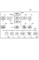
図1は、本実施形態に係る液晶表示装置100の構成例を示すブロック図である。液晶表示装置100は、投影光学系101、合成部102、液晶パネル103、分離部104、光源105を有する。光源105から出力された光は、分離部104で赤(R)、緑(G)、青(B)に分離され、それぞれ液晶パネル103R、103G、103Bに入射する。液晶パネル103R、103G、103Bをそれぞれ透過した光は合成部102で合成され、投影光学系101から不図示のスクリーン等に投影される。
(Embodiment 1)
FIG. 1 is a block diagram illustrating a configuration example of a liquid
本実施形態において、光源105は、複数の領域に分割された領域毎に点灯制御が可能であり、液晶パネルに対して、上部領域、中部領域、下部領域の3つの領域に分割して制御される。そして、液晶表示装置100は、通常投影モードと天吊り投影モードの2つの表示モードを有し、表示モードに応じて液晶パネルの走査方向を異ならせ、液晶パネルの走査方向に応じて、3つに分割された領域の点灯順を変える。光源の点灯タイミングを制御することで、液晶パネルの応答特性に起因する動きボケを低減することが可能となる。
In the present embodiment, the
投影光学系101は、複数のレンズ、レンズ駆動用のアクチュエータ等からなる。合成部102は、液晶パネル103R、103G、103Bを透過した赤(R)、緑(G)、青(B)の光を合成するものであり、例えば、ダイクロイックミラーやプリズムなどからなる。そして、合成部102により赤(R)、緑(G)、青(B)の成分を合成した光は、投影光学系101に送られる。
The projection
液晶パネル103Rは、赤色に対応する液晶素子であって、光源105から出力された光が分離部104で分離された、赤(R)、緑(G)、青(B)の光のうち、赤(R)の光の透過率を調整するためのものである。液晶パネル103Gは、緑色に対応する液晶素子であって、光源105から出力された光が分離部104で分離された、赤(R)、緑(G)、青(B)の光のうち、緑(G)の光の透過率を調整するためのものである。液晶パネル103Bは、青色に対応する液晶素子であって、光源105から出力された光が分離部104で分離された、赤(R)、緑(G)、青(B)の光のうち、青(B)の光の透過率を調整するためのものである。
The
分離部104は、光源105から出力された光を、赤(R)、緑(G)、青(B)に分離するものであり、例えば、ダイクロイックミラーやプリズムなどからなる。光源105は、不図示のスクリーンに画像を投影するための光を出力するものであり、例えば、ハロゲンランプ、キセノンランプ、高圧水銀ランプ、LEDなどで構成される。なお、光源105として、赤(R)、緑(G)、青(B)の各色に対応するLED等を使用する場合には、分離部104は不要である。
The
光学系制御部106は、アクチュエータを駆動してレンズの位置を調整することで、投影光学系101の制御を行い、スクリーンに投影する画像の拡大、縮小、焦点調整などを制御する。光学系制御部106は、投影光学系101を制御するマイクロプロセッサからなるが、専用のマイクロプロセッサでなく、例えば、ROM111に記憶されたプログラムによって、CPU110が光学系制御部106と同様の処理を実行しても良い。
The optical
液晶制御部107は、画像処理部108で処理された画像データに基づいて、画像データに対応する光の透過率となるように、液晶パネル103R、103G、103Bそれぞれの液晶素子に印加する電圧を制御するための走査信号を生成する。液晶制御部107は、生成した走査信号を用いて液晶パネル103を走査して、液晶パネルの透過率を調整する。そのため、液晶パネル103を透過し、合成部102により合成された光は、投影光学系101によりスクリーンに投影されると、画像処理部108により入力された画像データに対応する画像がスクリーン上に表示される。
Based on the image data processed by the
また液晶制御部107は、後述する液晶表示装置100の表示モードに応じて、液晶パネルの走査方向を変更することができる。液晶制御部107は、専用のマイクロプロセッサで構成しても、ROM111に記憶されたプログラムによって、CPU110が液晶制御部107と同様の処理を実行するように構成しても良い。
The liquid
画像処理部108は、表示する画像信号のフレーム数や、画素数、画像形状などに変更処理を施して、液晶制御部107に送信するものであり、例えば画像処理用のマイクロプロセッサからなる。画像処理部108は、表示する画像データに対して、フレーム間引き処理、フレーム補間処理、解像度変換処理、歪み補正処理(キーストン補正処理)といった機能を実行することが可能である。画像処理部108は、画像入力部114から入力された画像データや、通信部115から入力された画像データに対して、前述の処理を行う。また、画像処理部108は、液晶表示装置100を制御するための操作画面用の画像データを生成することもできる。画像処理部108は、専用のマイクロプロセッサである必要はなく、例えば、ROM111に記憶されたプログラムによって、CPU110が画像処理部108と同様の処理を実行しても良い。
The
光源制御部109は、光源105の点灯・消灯の制御や光量の制御をするものであり、制御用のマイクロプロセッサからなる。本実施形態において光源制御部109は、光源105を複数の領域に分割した領域毎に点灯制御が可能である。そして光源制御部109は、後述する液晶表示装置100の表示モードに応じて、複数の分割領域の点灯順序を変更することができる。なお、光源制御部160は、専用のマイクロプロセッサである必要はなく、例えば、ROM111に記憶されたプログラムによって、CPU110が光源制御部109と同様の処理を実行しても良い。
The light
CPU110は、液晶表示装置100の各動作ブロックを制御するものあり、ROM111は、CUP110の処理手順を記述した制御プログラムを記憶するためのものである。また、RAM112は、ワークメモリとして一時的に制御プログラムやデータを格納する。CPU110は、画像入力部114や通信部115から入力された画像データや動画データを一時的に記憶し、ROM111に記憶されたプログラムを用いて、それぞれの画像や映像を再生したりすることもできる。
The
操作部113は、ユーザの指示を受け付け、CPU110に指示に応じた制御信号を送信するものであり、例えば、スイッチやダイヤル、不図示の表示部上に設けられたタッチパネルなどからなる。また、操作部113は、例えば、リモコンからの信号を受信する信号受信部(赤外線受信部など)で、受信した信号に基づいて所定の指示信号をCPU110に送信するものであってもよい。CPU110は、操作部113や通信部115から入力された制御信号を受信して、液晶表示装置100の各動作ブロックを制御する。
The
画像入力部114は、外部装置から画像データを受信するものであり、例えば、コンポジット端子、S映像端子、D端子、コンポーネント端子、アナログRGB端子、DVI−I端子、DVI−D端子、HDMI(登録商標)端子等を含む。また、アナログ映像信号を受信した場合には、受信したアナログ映像信号をデジタル映像信号に変換する。そして、受信した映像信号を、画像処理部108に送信する。ここで外部装置とは、映像信号を出力できるものであればよく、例えば、パーソナルコンピュータ、カメラ、携帯電話、スマートフォン、ハードディスクレコーダ、ゲーム機などである。
The
通信部115は、外部機器からの制御信号や画像データなどを受信するためのものであり、例えば、無線LAN、有線LAN、USB、Bluetooth(登録商標)などで構成され、通信方式を特に限定するものではない。また、画像入力部114の端子が、例えばHDMI(登録商標)端子であれば、その端子を介してCEC通信を行うものであっても良い。内部バス116は、液晶表示装置100の各ブロックの間で、各種のデータやコマンドを転送するために用いられる。
The
また、液晶表示装置100は、図1に図示したブロック以外にも、記録媒体や記録媒体に対して画像データを保存、読み出しが可能な記録再生部を備えていてもよい。この場合、画像入力部114や通信部115から入力された画像データ等を、記録再生部により記録媒体に記録することが可能である。記録媒体は、液晶表示装置100に対して着脱可能な記録媒体であっても、内蔵型の記録媒体であってもよい。
In addition to the blocks shown in FIG. 1, the liquid
更に、液晶表示装置100は、表示部や表示制御部を備えていてもよく、表示制御部は表示部に、液晶表示装置100を操作するための操作画面やスイッチアイコン等の画像を表示させることができる。表示部は、液晶ディスプレイ、CRTディスプレイ、有機ELディスプレイ、LEDディスプレイなどのディスプレイであっても、ユーザに液晶表示装置100の状態を認識可能に掲示するために、各動作に対応するLED等を発光させるものであってもよい。
Furthermore, the liquid
また、液晶表示装置100は、レンズやレンズを駆動するアクチュエータを含む撮像部を有していてもよい。撮像部は、液晶表示装置100の周辺(例えばユーザ)を撮影して画像データを取得したり、投影光学系101により投影された画像を撮影(スクリーン方向を撮影)したりすることができる。
Further, the liquid
本実施形態における液晶表示装置100による投影処理の基本動作を説明する。操作部113や不図示のリモコンによりユーザが液晶表示装置100の電源のオンを指示すると、CPU110は、不図示の電源部から液晶表示装置100の各部に不図示の電源回路から電源を供給が供給する。
The basic operation of the projection processing by the liquid
CPU110は投影処理として、表示する画像データを画像処理部108に送信する。画像処理部108は、画像の画素数やフレームレートの変更、形状の変形等の必要な処理を実行し、処理された画像データを液晶制御部107に送信する。CPU110は、液晶制御部107に、受信した画像データの赤(R)、緑(G)、青(B)の各色成分の階調レベルに応じた透過率となるように、液晶パネル103R、103G、103Bそれぞれの透過率を制御させる。そして、CPU110は、光源制御部109に光源105からの光の出力を制御させる。
The
分離部104により、光源105から出力された光は、赤(R)、緑(G)、青(B)に分離され、それぞれの光は、液晶パネル103R、103G、103Bに供給される。液晶パネル103R、103G、103Bに供給された各色の光のうち、各液晶パネルの各画素の透過率に応じた光量が透過する。そして、液晶パネル103R、103G、103Bを透過した赤(R)、緑(G)、青(B)それぞれの光は、合成部102に供給され合成される。そして、合成部102で合成された光は、投影光学系101を介して、不図示のスクリーンに投影される。
The light output from the
以上の投影処理は、画像を投影している間、1フレーム分の画像データ毎に順次、実行されている。投影する画像は、画像入力部114や通信部115から入力された画像データや、画像処理部107が生成した走査画面等の画像データ、また不図示の記録媒体に記録された画像データや撮像部により撮影された画像データ等である。
The above projection processing is executed sequentially for each frame of image data while an image is being projected. The image to be projected includes image data input from the
次に、本実施形態における液晶表示装置100の表示モードについて説明する。本実施形態においては、通常投影モードと天吊り投影モードを有しているものとする。通常投影モードは、液晶表示装置100を机などの上に置いて使用する場合の表示モードであり、天吊り投影モードは、天井等から液晶表示装置100本体を逆さ向きに固定して使用する場合の表示モードである。
Next, the display mode of the liquid
図7(a)は、通常投影モードのときに、液晶パネルへ入力する画像と、液晶パネルの走査方向を示している。通常、入力される画像データは、画像の左上から順次入力されて液晶パネルの左上から順次走査され、出力される。 FIG. 7A shows an image input to the liquid crystal panel and the scanning direction of the liquid crystal panel in the normal projection mode. Normally, input image data is sequentially input from the upper left of the image, sequentially scanned from the upper left of the liquid crystal panel, and output.
一方天吊り投影モードにおいて、図7(b)のように、入力された画像データを左右上下に反転(180度回転)させて出力する場合、画像の左上のデータは液晶パネルの右下に入力されるため、入力される画像データは、液晶パネルの右下から順次走査される。天吊り投影モードにおいては、液晶パネルへ入力する画像データ自体を180度回転させ、通常投影モードと同様に液晶パネルの左上から右下に向かって順次走査する方法もある。しかし、入力するための画像データを、180度回転させて作成する処理に時間を要するため、液晶パネルを走査するまでに遅延が発生してしまう。よって、本実施例において天吊り投影モードでは、入力された画像データを左右上下に反転(180度回転)させて出力する。 On the other hand, in the ceiling-mounted projection mode, as shown in FIG. 7B, when the input image data is reversed left and right and up and down (rotated 180 degrees) and output, the upper left data of the image is input to the lower right of the liquid crystal panel. Therefore, the input image data is sequentially scanned from the lower right of the liquid crystal panel. In the ceiling-mounted projection mode, there is a method in which image data input to the liquid crystal panel itself is rotated 180 degrees and sequentially scanned from the upper left to the lower right of the liquid crystal panel, as in the normal projection mode. However, since it takes time to create image data to be input by rotating it 180 degrees, a delay occurs until the liquid crystal panel is scanned. Therefore, in this embodiment, in the ceiling projection mode, the input image data is inverted left and right and up and down (rotated 180 degrees) and output.
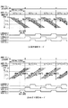
図8に通常投影モードと天吊り投影モードとにおける、液晶パネルの垂直走査方向と光源の点灯制御の概略図を示す。図8に示す制御では、光源の点灯制御は、通常投影モードと天吊り投影モードとで同じである。液晶パネルは垂直方向にLライン分の液晶素子を有し、通常投影モードでは上部領域(0ライン)から走査され、天吊り投影モードでは下部領域(L−1ライン)から走査される。グレー色部分の期間T1では、表示する画像データに基づいた液晶パネルの目標透過率に対する実際の透過率の割合が、所定値未満となっている。そして白色部分の期間T2では、表示する画像データに基づいた液晶パネルの目標透過率に対する実際の透過率の割合が、所定値以上となっているものとする。 FIG. 8 shows a schematic diagram of the vertical scanning direction of the liquid crystal panel and the lighting control of the light source in the normal projection mode and the ceiling projection mode. In the control shown in FIG. 8, the lighting control of the light source is the same in the normal projection mode and the ceiling projection mode. The liquid crystal panel has liquid crystal elements for L lines in the vertical direction, and is scanned from the upper region (0 line) in the normal projection mode, and is scanned from the lower region (L-1 line) in the ceiling projection mode. In the period T1 of the gray color portion, the ratio of the actual transmittance to the target transmittance of the liquid crystal panel based on the image data to be displayed is less than a predetermined value. In the period T2 of the white portion, it is assumed that the ratio of the actual transmittance to the target transmittance of the liquid crystal panel based on the image data to be displayed is a predetermined value or more.
図7(a)に示すように、光源を液晶パネルに対して垂直方向に上部(A1)、中部(A2)、下部(A3)の3つの領域に分割して制御する場合、通常投影モードでは、図8(a)に示すように光源は上部から順に分割領域A1、A2、A3の順で点灯させる。このようにすることで、点灯している分割領域に対応する液晶パネルの領域において、表示する画像データに基づいた液晶パネルの目標透過率に対する実際の透過率の割合が所定値以上となり、動きボケを低減できる。 As shown in FIG. 7A, when the light source is controlled by being divided into three regions of an upper part (A1), a middle part (A2), and a lower part (A3) in a direction perpendicular to the liquid crystal panel, the normal projection mode is used. As shown in FIG. 8A, the light source is turned on in the order of the divided areas A1, A2, and A3 from the top. In this way, in the area of the liquid crystal panel corresponding to the divided area that is lit, the ratio of the actual transmittance to the target transmittance of the liquid crystal panel based on the image data to be displayed becomes a predetermined value or more, and motion blur is caused. Can be reduced.
しかし、天吊り投影モードにおいては、図8(b)に示すように制御すると、液晶パネルは分割領域A3に対応する下部領域から走査されていく。そのため、通常投影モードと同様に光源を制御すると、分割領域A1が点灯しているとき、分割領域A1に対応する液晶パネルの上部領域では期間T1にあり、まだ液晶パネルの目標透過率に対する実際の透過率の割合が、所定値に達していない。 However, in the ceiling projection mode, when the control is performed as shown in FIG. 8B, the liquid crystal panel is scanned from the lower area corresponding to the divided area A3. Therefore, when the light source is controlled in the same manner as in the normal projection mode, when the divided area A1 is lit, the upper area of the liquid crystal panel corresponding to the divided area A1 is in the period T1, and is still actual with respect to the target transmittance of the liquid crystal panel. The transmittance ratio does not reach the predetermined value.
図2(a)は、本実施形態における光源105の点灯制御を行う分割領域を示す。光源105は、複数の領域に分割された領域毎に点灯制御が可能であり、本実施形態では、液晶パネル(「F」の画像を表示)に対して、上部領域(分割領域A1)、中部領域(分割領域A2)、下部領域(分割領域A3)の3つの領域に分割して制御される。
FIG. 2A shows a divided region in which lighting control of the
図3(a)は、複数の領域に分割された領域毎に点灯制御するための光源105の概略図を示す。図3(a)に示す光源105は、光源ユニット301〜303、レンズ304〜306で構成される。例えば、光源ユニット301〜303はLED、レンズ304及びレンズ305はフライアイレンズであり、レンズ306はコンデンサレンズである。光源ユニット301〜303から出力されたそれぞれの平行光束は、レンズ304〜306を透過して、被照射面(液晶パネル)307の全域を均一に照射することが可能になる。本実施形態においては、レンズ306と被照射面307の間に、図1に示す分離部104を設ける。光源ユニット301〜303から出力され、レンズ304〜306を透過した光は、分離部104により赤(R)、緑(G)、青(B)に分離される。分離された光がそれぞれ液晶パネル103R、103G、103Bに入射することになる。
Fig.3 (a) shows the schematic of the
図3(b)は、各光源ユニットと液晶パネル上での各分割領域の点灯状態の関係を示している。図3(a)に示した光源105を用いることで、図3(b)に示すように、複数の領域に分割された領域毎に点灯制御が可能である。光源ユニット301により液晶パネルの上部領域(分割領域A1)が点灯し、光源ユニット302により液晶パネルの中部領域(分割領域A2)が点灯し、光源ユニット303により液晶パネルの下部領域(分割領域A3)が点灯する。
FIG. 3B shows the relationship between the light source units and the lighting states of the divided areas on the liquid crystal panel. By using the
図4は、本実施形態における、液晶表示装置100の表示モードの切り替えによる制御処理を示すフローチャートである。図4の処理はCPU110が各部を制御することにより実行される。図4の処理は、液晶表示装置100の電源が入れられたときや、操作部113等からユーザにより表示モードに関する指示が入力された場合に開始される。
FIG. 4 is a flowchart showing a control process by switching the display mode of the liquid
CPU110は、ステップS401において、表示モードが天吊り投影モードか否かを判別する。通常投影モードである場合(ステップS401でNo)には、ステップS402においてCPU110は、液晶制御部107に、液晶パネル103の上部領域から下部領域に走査するように制御させる。通常投影モードでは、液晶制御部107は、入力される画像データに応じて、液晶パネル103を上部領域から下部領域の方向へ走査する。具体的には、液晶パネルは左上から走査が開始され、水平走査方向は左から右の方向、垂直走査方向は上から下の方向になるように、順次走査される。
In step S401, the
図5(a)に本実施形態の通常投影モードにおける、液晶パネルの垂直走査方向と光源の点灯制御の概略図を示す。通常投影モードでは、液晶パネル103は上部領域(0ライン)から順次走査される。グレー色部分の期間T1では、表示する画像データに基づいた液晶パネルの目標透過率に対する実際の透過率の割合が、所定値未満となっている。そして白色部分の期間T2では、表示する画像データに基づいた液晶パネルの目標透過率に対する実際の透過率の割合が、所定値以上となっているものとする。
FIG. 5A shows a schematic diagram of the vertical scanning direction of the liquid crystal panel and the light source lighting control in the normal projection mode of the present embodiment. In the normal projection mode, the
図5に示す、各分割領域の点灯時間は、予め設定されている時間でもよいし、ROM111に予め記憶しておいた液晶パネルの応答特性や、随時測定した液晶パネルの応答特性に基づいて求めた時間でもよい。図5に示した各分割領域の制御パルス信号では、各分割領域の点灯時間が他の分割領域の点灯時間と重ならないように設定されているが、同時に複数の分割領域が点灯する時間を設けてもよい。液晶パネルが1フレーム分の画像データに基づく走査信号により駆動されている状態で、複数の領域に分割した全ての分割領域が点灯するように、各分割領域の点灯時間を調整する。
The lighting time of each divided region shown in FIG. 5 may be a preset time, or obtained based on the response characteristics of the liquid crystal panel stored in advance in the
またCPU110は、ステップS403において、光源制御部109に、複数の領域に分割された光源105の上部領域から順次下部領域が点灯するように制御させる。具体的には光源制御部109は、分割領域A1、A2、A3の順に点灯するように制御する。光源制御部109は、各分割領域が対応する液晶パネルの領域の透過率において、表示する画像データに基づいた液晶パネルの目標透過率に対する実際の透過率の割合が所定値以上となっている状態で、各分割領域が点灯するように制御するのが望ましい。このように制御することで、動きボケを低減することが可能になる。
In step S <b> 403, the
ステップS401において天吊り投影モードであった場合には、ステップS404においてCPU110は、液晶制御部107に、液晶パネル103の下部領域から上部領域に走査するように制御させる。天吊り投影モードでは、通常投影モードの際に液晶パネルの入力される画像に対して左右及び上下が反転した画像が入力される。つまり、液晶パネルの右下部分から走査するべき画像データから順次液晶制御部107に入力され、図7(b)に示すように、液晶パネルの水平走査方向は右から左の方向、垂直走査方向は下から上の方向となる。
If it is the ceiling projection mode in step S401, in step S404, the
続いてCPU110は、ステップS405において、光源制御部109に、複数の領域に分割された光源105の点灯順序を、下部領域から順次上部領域が点灯するように制御させる。具体的には光源制御部109は、分割領域A3、A2、A1の順に点灯するように制御する。図5(b)に天吊り投影モードにおける、液晶パネルの垂直走査方向と光源の点灯制御の概略図を示す。天吊り投影モードでは、液晶パネル103は下部領域(L−1ライン)から順次走査される。
Subsequently, in step S405, the
ステップS406において、CPU110はユーザ等により表示モードが変更されたか否かを判別し、表示モードが変更されたらステップS401に戻って処理を続ける。表示モードが変更されない場合には、液晶制御部107及び光源制御部109を制御するための設定を、CPU110はROM111に記録して本処理を終了する。
In step S406, the
本実施形態のように、光源105の各分割領域の点灯時間を1フレームの表示時間より短く設定することで、光源105の全分割領域を常時点灯する場合に比べると、投影される画像の明るさが落ちるという課題がある。この課題に対しては、光源に印加する電流値を制御して、各分割領域の光量を増加させることで対応可能である。また、CPU110は、各分割領域に対応する画像データの値に応じて決定した各分割領域の発光量で、各分割領域の点灯を制御するように光源制御部109を制御すると共に、液晶制御部107により画像データが調整されるように制御してもよい。
As in this embodiment, by setting the lighting time of each divided region of the
以上のように、異なる表示モードを有する表示装置において、表示パネルの走査方向が変わる場合においても、光源の点灯タイミングを制御することで、表示パネルの応答特性に起因する動きボケを低減することができる。 As described above, in a display device having different display modes, even when the scanning direction of the display panel changes, motion blur caused by response characteristics of the display panel can be reduced by controlling the lighting timing of the light source. it can.
(実施形態2)
本実施形態においては、図2(b)に示すように、光源105が9つの分割領域a1〜a9に分割して点灯制御が可能となっている点が実施形態1と異なる。また、本実施形態においては、実施形態1で説明した通常投影モードと天吊り投影モードに加えて、天吊りリアプロ(リアプロジェクション)投影モードを有する。
(Embodiment 2)
In the present embodiment, as shown in FIG. 2B, the
本実施形態において、光源105は、液晶パネルに対して、上部領域、中部領域、下部領域、更に光源側から表示パネルに対して右側、中央、左側の全部で9つの領域に分割して制御される。実施形態1では図3(a)に示したように、光源105の光源ユニットが一次元方向(上下方向)に配置されたが、本実施形態では光源ユニットは、二次元的(上下左右)に9つ配置される。そして、液晶表示装置100は、通常投影モード、天吊り投影モード、天吊りリアプロ投影モードの3つの表示モードを有し、表示モードに応じて液晶パネルの走査方向を異ならせ、液晶パネルの走査方向に応じて、9つに分割された領域の点灯順を変える。光源の点灯タイミングを制御することで、液晶パネルの透過率に起因する動きボケを低減することが可能となる。
In the present embodiment, the
天吊りリアプロ投影モードは、天井等から液晶表示装置100本体を逆さ向きに固定して、スクリーンの背面から投影する方式で用いられる。図6に、通常投影モード、天吊り投影モード、及び天吊りリアプロ投影モードにおける、液晶パネルの走査方向と各分割領域の概略図を示す。いずれも入力される画像は、図7と同様に「F」を表示した画像である。
The ceiling-mounted rear professional projection mode is used in a system in which the liquid
通常投影モード(図6(a))では、液晶パネルの左上に入力されるべきデータから液晶パネルに入力される。よって液晶パネルは、液晶パネルの左上部分から走査を開始され、水平走査方向は左から右の方向、垂直走査方向は上から下の方向になるように順次走査される。天吊り投影モード(図6(b))は、液晶パネルの右下に入力されるべきデータから液晶パネルに入力されるので、液晶パネルは、液晶パネルの右下部分から走査を開始され、水平走査方向は右から左の方向、垂直走査方向は下から上の方向となる。 In the normal projection mode (FIG. 6A), data to be input to the upper left of the liquid crystal panel is input to the liquid crystal panel. Accordingly, the liquid crystal panel starts scanning from the upper left portion of the liquid crystal panel, and is sequentially scanned so that the horizontal scanning direction is the left to right direction and the vertical scanning direction is the top to bottom direction. In the ceiling projection mode (FIG. 6B), since the data to be input to the lower right of the liquid crystal panel is input to the liquid crystal panel, the liquid crystal panel starts scanning from the lower right portion of the liquid crystal panel, and the horizontal The scanning direction is from right to left, and the vertical scanning direction is from bottom to top.
天吊りリアプロ投影モード(図6(c))は、通常投影モードの際に液晶パネルの入力される画像に対して上下が反転した画像が入力される。よって、液晶パネルの左下に入力されるべきデータから液晶パネルに入力されるので、液晶パネルは、液晶パネルの左下部分から走査を開始される。そして液晶パネルの水平走査方向が左から右の方向、垂直走査方向が下から上の方向になるように、液晶パネルが順次走査される。 In the ceiling-mounted rear professional projection mode (FIG. 6C), an image that is inverted upside down with respect to an image input on the liquid crystal panel in the normal projection mode is input. Therefore, since data to be input to the lower left of the liquid crystal panel is input to the liquid crystal panel, the liquid crystal panel starts scanning from the lower left portion of the liquid crystal panel. The liquid crystal panels are sequentially scanned so that the horizontal scanning direction of the liquid crystal panel is from left to right and the vertical scanning direction is from bottom to top.
よって、通常投影モードにおいては、分割領域a1、a2、a3、a4、a5、a6、a7、a8、a9の順に点灯するように、光源制御部109は光源105の制御を行う。また、天吊り投影モードにおいては、分割領域a9、a8、a7、a6、a5、a4、a3、a2、a1の順に点灯するように、光源制御部109は光源105の制御を行う。また、天吊りリアプロ投影モードにおいては、分割領域a7、a8、a9、a4、a5、a6、a1、a2、a3の順に点灯するように、光源制御部109は光源105の制御を行う。
Therefore, in the normal projection mode, the light
なお、液晶表示装置100を机などの上に置いてスクリーンの背面から投影するリアプロ投影モードでは、左右反転した画像が入力されるので、液晶パネルの右上に入力されるべきデータから液晶パネルに入力される。よって、液晶パネルは、液晶パネルの右上部分から走査を開始され、液晶パネルの水平走査方向が右から左の方向、垂直走査方向が上から下の方向になるように、液晶パネルが順次走査される。そして光源制御部109は、液晶パネルの走査順に同期するように、光源105の各分割領域を、分割領域a3、a2、a1、a6、a5、a4、a9、a8、a7の順に点灯するように制御する。
In the rear-pro projection mode in which the liquid
また、液晶表示装置100を90度回転させて使用する表示モードの場合にも、液晶制御部107が液晶パネル103の走査方向を変更したら、その走査方向に応じて光源制御部109が点灯制御する光源105の各分割領域の点灯順も変更される。例えば右に90度回転させて液晶表示装置を使用する場合、表示する画像の左上のデータが、液晶パネルの左下に入力されるべきデータとして液晶パネルに入力される。よって、液晶パネルは、液晶パネルの左下部分から走査を開始され、左下部分から左上部分へ走査される。つまり、液晶パネルの垂直(液晶パネルの短辺方向)走査方向が下から上の方向、水平(液晶パネルの長辺方向)走査方向は右から左の方向になるように、液晶パネルが順次走査される。この場合、光源制御部109は光源105の各分割領域を、分割領域a7、a4、a1、a8、a5、a2、a9、a6、a3の順に点灯するように制御する。
Even in the display mode in which the liquid
以上のように、本実施形態においても、異なる表示モードを有する表示装置で、表示パネルの垂直走査方向または水平走査方向が変わる場合でも、光源の点灯タイミングを制御することで、表示パネルの応答特性に起因する動きボケを低減することができる。 As described above, also in this embodiment, even when the vertical scanning direction or the horizontal scanning direction of the display panel is changed in a display device having different display modes, the response characteristic of the display panel is controlled by controlling the lighting timing of the light source. It is possible to reduce the motion blur caused by.
101 投影光学系
103 液晶パネル
105 光源
106 光学系制御部
107 液晶制御部
108 画像処理部
109 光源制御部
110 CPU
DESCRIPTION OF
Claims (8)
前記表示パネルに対応した領域に対して、複数に分割された領域毎に点灯制御が可能な光源を制御する光源制御手段と、を有し、
前記表示制御手段は、前記複数の表示モードに応じて、前記表示パネルの走査方向を異ならせ、
前記光源制御手段は、前記表示パネルの走査方向に応じて、前記複数に分割された領域の点灯順を変えることを特徴とする表示装置。 Display control means for controlling the scanning direction of the display panel according to a plurality of display modes;
A light source control means for controlling a light source capable of lighting control for each of the regions divided into a plurality of regions corresponding to the display panel;
The display control means varies the scanning direction of the display panel according to the plurality of display modes,
The light source control means changes the lighting order of the divided areas according to the scanning direction of the display panel.
第2の表示モードにおいて、前記表示制御手段は、前記表示パネルの下部から上部へ走査を行うように制御し、前記光源制御手段は、前記表示パネルの下部に対応した光源から順次前記上部に対応した光源を点灯させるように制御することを特徴とする請求項1または2に記載の表示装置。 In the first display mode, the display control means controls to scan from the upper part to the lower part of the display panel, and the light source control means sequentially corresponds to the lower part from the light source corresponding to the upper part of the display panel. Control to turn on the light source,
In the second display mode, the display control means controls to scan from the lower part to the upper part of the display panel, and the light source control means sequentially corresponds to the upper part from the light source corresponding to the lower part of the display panel. The display device according to claim 1, wherein the display is controlled so that the light source is turned on.
前記表示パネルに対応した領域に対して、複数に分割された領域毎に点灯制御が可能な光源を制御する光源制御ステップと、を有し、
前記表示制御ステップにおいて、第1の表示モードと第2の表示モードとで、前記表示パネルの走査方向を異ならせ、
前記光源制御ステップにおいては、前記表示パネルの走査方向に応じて、前記複数に分割された領域の点灯順を変えることを特徴とする表示装置の制御方法。 A display control step for controlling the scanning direction of the display panel according to the display mode;
A light source control step for controlling a light source capable of lighting control for each of the regions divided into a plurality of regions corresponding to the display panel;
In the display control step, the scanning direction of the display panel is changed between the first display mode and the second display mode,
In the light source control step, the lighting order of the divided areas is changed according to the scanning direction of the display panel.
Priority Applications (6)
| Application Number | Priority Date | Filing Date | Title |
|---|---|---|---|
| JP2013255673A JP2015114443A (en) | 2013-12-11 | 2013-12-11 | Display device and control method of display device |
| CN201480066110.6A CN105793774B (en) | 2013-12-11 | 2014-12-03 | Lamp optical system, image projecting equipment and its control method |
| PCT/JP2014/006033 WO2015087512A1 (en) | 2013-12-11 | 2014-12-03 | Illumination optical system, image projection apparatus, and control method thereof |
| US15/027,545 US9800848B2 (en) | 2013-12-11 | 2014-12-03 | Illumination optical system, image projection apparatus, and control method thereof |
| US14/563,477 US10037734B2 (en) | 2013-12-11 | 2014-12-08 | Display apparatus and control method |
| CN201410768542.3A CN104714333B (en) | 2013-12-11 | 2014-12-11 | Display device and control method |
Applications Claiming Priority (1)
| Application Number | Priority Date | Filing Date | Title |
|---|---|---|---|
| JP2013255673A JP2015114443A (en) | 2013-12-11 | 2013-12-11 | Display device and control method of display device |
Publications (2)
| Publication Number | Publication Date |
|---|---|
| JP2015114443A true JP2015114443A (en) | 2015-06-22 |
| JP2015114443A5 JP2015114443A5 (en) | 2017-01-19 |
Family
ID=53271782
Family Applications (1)
| Application Number | Title | Priority Date | Filing Date |
|---|---|---|---|
| JP2013255673A Pending JP2015114443A (en) | 2013-12-11 | 2013-12-11 | Display device and control method of display device |
Country Status (3)
| Country | Link |
|---|---|
| US (1) | US10037734B2 (en) |
| JP (1) | JP2015114443A (en) |
| CN (1) | CN104714333B (en) |
Cited By (1)
| Publication number | Priority date | Publication date | Assignee | Title |
|---|---|---|---|---|
| WO2018062016A1 (en) * | 2016-09-29 | 2018-04-05 | シャープ株式会社 | Display device with backlight |
Families Citing this family (3)
| Publication number | Priority date | Publication date | Assignee | Title |
|---|---|---|---|---|
| JP6700731B2 (en) * | 2015-11-13 | 2020-05-27 | キヤノン株式会社 | Projection device and projection system |
| KR102577409B1 (en) * | 2016-08-22 | 2023-09-14 | 엘지디스플레이 주식회사 | Controller, display device, and the method for driving the display device |
| CN107292236B (en) | 2017-05-22 | 2019-12-13 | Oppo广东移动通信有限公司 | fingerprint acquisition method and related product |
Citations (10)
| Publication number | Priority date | Publication date | Assignee | Title |
|---|---|---|---|---|
| JPH08307745A (en) * | 1995-04-20 | 1996-11-22 | Samsung Electron Co Ltd | Video camera with liquid crystal monitor and tv projector adaptor |
| JPH11287987A (en) * | 1998-04-03 | 1999-10-19 | Citizen Watch Co Ltd | Electronic equipment |
| JP2000321993A (en) * | 1999-05-11 | 2000-11-24 | Matsushita Electric Ind Co Ltd | Display panel and its manufacture, display method and display device using the method and digital camera mounting the display device, viewfinder, and image processing method |
| JP2001125066A (en) * | 1999-10-29 | 2001-05-11 | Hitachi Ltd | Liquid crystal display device |
| US20060050047A1 (en) * | 2002-06-18 | 2006-03-09 | Samsung Electronics Co., Ltd. | Liquid crystal display for performing time divisional color display, method of driving the same backlight unit for liquid crystal display |
| JP2006330329A (en) * | 2005-05-26 | 2006-12-07 | Seiko Epson Corp | Multi-projection display |
| WO2007007472A1 (en) * | 2005-07-07 | 2007-01-18 | Sharp Kabushiki Kaisha | Display unit |
| JP2009063751A (en) * | 2007-09-05 | 2009-03-26 | Hitachi Displays Ltd | Liquid crystal display device |
| JP2009168977A (en) * | 2008-01-15 | 2009-07-30 | Seiko Epson Corp | Projector |
| JP2010175907A (en) * | 2009-01-30 | 2010-08-12 | Victor Co Of Japan Ltd | Projection display device and method for displaying the same |
Family Cites Families (29)
| Publication number | Priority date | Publication date | Assignee | Title |
|---|---|---|---|---|
| JP2643495B2 (en) * | 1989-11-20 | 1997-08-20 | 松下電器産業株式会社 | Liquid crystal display |
| JP2001350426A (en) | 2000-06-08 | 2001-12-21 | Canon Inc | Image display device, image display system and illumination system |
| JP2002055657A (en) * | 2000-08-08 | 2002-02-20 | Sharp Corp | Video display device |
| TW575864B (en) * | 2001-11-09 | 2004-02-11 | Sharp Kk | Liquid crystal display device |
| TW200303001A (en) * | 2001-11-09 | 2003-08-16 | Sharp Kk | Liquid crystal display device |
| EP1522985A3 (en) * | 2003-10-08 | 2008-11-19 | LG Electronics Inc. | System and method for driving a display panel of mobile terminal |
| JP2006154025A (en) | 2004-11-26 | 2006-06-15 | Seiko Epson Corp | Image display device |
| US8836621B2 (en) * | 2004-12-15 | 2014-09-16 | Nlt Technologies, Ltd. | Liquid crystal display apparatus, driving method for same, and driving circuit for same |
| US8063922B2 (en) * | 2005-09-15 | 2011-11-22 | Sharp Kabushiki Kaisha | Liquid crystal display device |
| JP2007127955A (en) | 2005-11-07 | 2007-05-24 | Matsushita Electric Ind Co Ltd | Illuminator and projection type image display device |
| TWI273546B (en) * | 2006-01-26 | 2007-02-11 | Au Optronics Corp | Method and device for driving LCD panel |
| US8106865B2 (en) * | 2006-06-02 | 2012-01-31 | Semiconductor Energy Laboratory Co., Ltd. | Display device and driving method thereof |
| FR2905027B1 (en) * | 2006-08-21 | 2013-12-20 | Lg Philips Lcd Co Ltd | LIQUID CRYSTAL DISPLAY DEVICE AND ITS CONTROL METHOD |
| JP4478670B2 (en) | 2006-09-08 | 2010-06-09 | ソニー株式会社 | One-dimensional illumination device and image generation device |
| TWI331741B (en) * | 2006-10-14 | 2010-10-11 | Au Optronics Corp | System and driving method for color sequencial liquid crystal display (lcd) |
| US8274532B2 (en) * | 2006-11-10 | 2012-09-25 | Draeger Medical Systems, Inc. | System for adaptively orienting a display image on a device |
| JP5177999B2 (en) * | 2006-12-05 | 2013-04-10 | 株式会社半導体エネルギー研究所 | Liquid crystal display |
| JP4740888B2 (en) | 2007-03-05 | 2011-08-03 | シャープ株式会社 | Liquid crystal display |
| JP4137162B2 (en) | 2007-04-20 | 2008-08-20 | 三洋電機株式会社 | Projection display device |
| JP5197227B2 (en) | 2008-08-19 | 2013-05-15 | キヤノン株式会社 | Illumination optical system and image projection apparatus |
| JP2009116351A (en) | 2009-01-13 | 2009-05-28 | Seiko Epson Corp | Image display apparatus |
| JP2010271365A (en) * | 2009-05-19 | 2010-12-02 | Sony Corp | Display controller and method for controlling display |
| JP2011022524A (en) | 2009-07-21 | 2011-02-03 | Hitachi Consumer Electronics Co Ltd | Projection video display apparatus |
| JP2011227225A (en) * | 2010-04-19 | 2011-11-10 | Hitachi Displays Ltd | Display device |
| TWI413090B (en) * | 2010-05-05 | 2013-10-21 | Au Optronics Corp | Backlight driving method and display |
| EP2642178B1 (en) | 2010-11-17 | 2020-06-17 | Nec Display Solutions, Ltd | Light source apparatus, lighting apparatus, and projection-type display apparatus |
| JP5987382B2 (en) | 2011-07-22 | 2016-09-07 | 株式会社リコー | LIGHTING DEVICE, PROJECTION DEVICE, AND METHOD FOR CONTROLLING PROJECTION DEVICE |
| KR101481675B1 (en) * | 2011-10-04 | 2015-01-22 | 엘지디스플레이 주식회사 | Bidirectional shift register |
| JP5798585B2 (en) * | 2013-03-14 | 2015-10-21 | 双葉電子工業株式会社 | Display device, scanning line driving device |
-
2013
- 2013-12-11 JP JP2013255673A patent/JP2015114443A/en active Pending
-
2014
- 2014-12-08 US US14/563,477 patent/US10037734B2/en not_active Expired - Fee Related
- 2014-12-11 CN CN201410768542.3A patent/CN104714333B/en not_active Expired - Fee Related
Patent Citations (10)
| Publication number | Priority date | Publication date | Assignee | Title |
|---|---|---|---|---|
| JPH08307745A (en) * | 1995-04-20 | 1996-11-22 | Samsung Electron Co Ltd | Video camera with liquid crystal monitor and tv projector adaptor |
| JPH11287987A (en) * | 1998-04-03 | 1999-10-19 | Citizen Watch Co Ltd | Electronic equipment |
| JP2000321993A (en) * | 1999-05-11 | 2000-11-24 | Matsushita Electric Ind Co Ltd | Display panel and its manufacture, display method and display device using the method and digital camera mounting the display device, viewfinder, and image processing method |
| JP2001125066A (en) * | 1999-10-29 | 2001-05-11 | Hitachi Ltd | Liquid crystal display device |
| US20060050047A1 (en) * | 2002-06-18 | 2006-03-09 | Samsung Electronics Co., Ltd. | Liquid crystal display for performing time divisional color display, method of driving the same backlight unit for liquid crystal display |
| JP2006330329A (en) * | 2005-05-26 | 2006-12-07 | Seiko Epson Corp | Multi-projection display |
| WO2007007472A1 (en) * | 2005-07-07 | 2007-01-18 | Sharp Kabushiki Kaisha | Display unit |
| JP2009063751A (en) * | 2007-09-05 | 2009-03-26 | Hitachi Displays Ltd | Liquid crystal display device |
| JP2009168977A (en) * | 2008-01-15 | 2009-07-30 | Seiko Epson Corp | Projector |
| JP2010175907A (en) * | 2009-01-30 | 2010-08-12 | Victor Co Of Japan Ltd | Projection display device and method for displaying the same |
Cited By (1)
| Publication number | Priority date | Publication date | Assignee | Title |
|---|---|---|---|---|
| WO2018062016A1 (en) * | 2016-09-29 | 2018-04-05 | シャープ株式会社 | Display device with backlight |
Also Published As
| Publication number | Publication date |
|---|---|
| CN104714333B (en) | 2017-12-01 |
| US10037734B2 (en) | 2018-07-31 |
| US20150161952A1 (en) | 2015-06-11 |
| CN104714333A (en) | 2015-06-17 |
Similar Documents
| Publication | Publication Date | Title |
|---|---|---|
| US10148924B2 (en) | Projection apparatus, method of controlling projection apparatus, and projection system | |
| US10171781B2 (en) | Projection apparatus, method for controlling the same, and projection system | |
| JP2017147634A (en) | Projection device, projection method, and projection system | |
| US10037734B2 (en) | Display apparatus and control method | |
| JP6707871B2 (en) | Image quality correction method and image projection system | |
| JP6208930B2 (en) | Projection apparatus, control method therefor, program, and storage medium | |
| JP2016161752A (en) | Image processing device, display device, and image processing method | |
| JP6794092B2 (en) | Display device | |
| US20130335643A1 (en) | Projection-type image display device and light quantity adjustment method | |
| JP6635748B2 (en) | Display device, display device control method, and program | |
| JP2015053558A (en) | Image display device and method for controlling the same | |
| US10349026B2 (en) | Projector, method for controlling the same, and projection system | |
| JP2016184775A (en) | Video processing device, display device, video processing method | |
| US20180376031A1 (en) | Projection apparatus that improves dynamic range of luminance of printed material, control method therefor, and storage medium | |
| JP2016161753A (en) | Video processing device, display device, and video processing method | |
| JP6545034B2 (en) | Display device, display method and display system | |
| JP2020072357A (en) | Projection apparatus and projection method | |
| JP2019114887A (en) | Projection type image display device and control method thereof | |
| JP7309352B2 (en) | Electronic equipment and its control method | |
| JP6562653B2 (en) | Projection device | |
| JP2018180105A (en) | Projection device and image projection method | |
| JP2019208169A (en) | Projection apparatus, control method of the same, program, and storage medium | |
| JP2014036394A (en) | Distortion correction method of projection image and projection display device | |
| JP2022043498A (en) | Projection type display device and projection type display system | |
| JP6103855B2 (en) | Projection apparatus, control method therefor, program, and storage medium |
Legal Events
| Date | Code | Title | Description |
|---|---|---|---|
| A521 | Request for written amendment filed |
Free format text: JAPANESE INTERMEDIATE CODE: A523 Effective date: 20161130 |
|
| A621 | Written request for application examination |
Free format text: JAPANESE INTERMEDIATE CODE: A621 Effective date: 20161130 |
|
| A131 | Notification of reasons for refusal |
Free format text: JAPANESE INTERMEDIATE CODE: A131 Effective date: 20170829 |
|
| A521 | Request for written amendment filed |
Free format text: JAPANESE INTERMEDIATE CODE: A523 Effective date: 20171027 |
|
| A02 | Decision of refusal |
Free format text: JAPANESE INTERMEDIATE CODE: A02 Effective date: 20180313 |