JP2015089383A - Ultrasonic probe and ultrasonic measuring apparatus - Google Patents
Ultrasonic probe and ultrasonic measuring apparatus Download PDFInfo
- Publication number
- JP2015089383A JP2015089383A JP2013229058A JP2013229058A JP2015089383A JP 2015089383 A JP2015089383 A JP 2015089383A JP 2013229058 A JP2013229058 A JP 2013229058A JP 2013229058 A JP2013229058 A JP 2013229058A JP 2015089383 A JP2015089383 A JP 2015089383A
- Authority
- JP
- Japan
- Prior art keywords
- unit
- measurement
- ultrasonic
- light
- light emitting
- Prior art date
- Legal status (The legal status is an assumption and is not a legal conclusion. Google has not performed a legal analysis and makes no representation as to the accuracy of the status listed.)
- Withdrawn
Links
Images


Classifications
-
- A—HUMAN NECESSITIES
- A61—MEDICAL OR VETERINARY SCIENCE; HYGIENE
- A61B—DIAGNOSIS; SURGERY; IDENTIFICATION
- A61B8/00—Diagnosis using ultrasonic, sonic or infrasonic waves
- A61B8/08—Detecting organic movements or changes, e.g. tumours, cysts, swellings
- A61B8/0891—Detecting organic movements or changes, e.g. tumours, cysts, swellings for diagnosis of blood vessels
-
- A—HUMAN NECESSITIES
- A61—MEDICAL OR VETERINARY SCIENCE; HYGIENE
- A61B—DIAGNOSIS; SURGERY; IDENTIFICATION
- A61B5/00—Measuring for diagnostic purposes; Identification of persons
- A61B5/0033—Features or image-related aspects of imaging apparatus classified in A61B5/00, e.g. for MRI, optical tomography or impedance tomography apparatus; arrangements of imaging apparatus in a room
- A61B5/0035—Features or image-related aspects of imaging apparatus classified in A61B5/00, e.g. for MRI, optical tomography or impedance tomography apparatus; arrangements of imaging apparatus in a room adapted for acquisition of images from more than one imaging mode, e.g. combining MRI and optical tomography
-
- A—HUMAN NECESSITIES
- A61—MEDICAL OR VETERINARY SCIENCE; HYGIENE
- A61B—DIAGNOSIS; SURGERY; IDENTIFICATION
- A61B5/00—Measuring for diagnostic purposes; Identification of persons
- A61B5/0059—Measuring for diagnostic purposes; Identification of persons using light, e.g. diagnosis by transillumination, diascopy, fluorescence
- A61B5/0062—Arrangements for scanning
- A61B5/0064—Body surface scanning
-
- A—HUMAN NECESSITIES
- A61—MEDICAL OR VETERINARY SCIENCE; HYGIENE
- A61B—DIAGNOSIS; SURGERY; IDENTIFICATION
- A61B8/00—Diagnosis using ultrasonic, sonic or infrasonic waves
- A61B8/42—Details of probe positioning or probe attachment to the patient
- A61B8/4245—Details of probe positioning or probe attachment to the patient involving determining the position of the probe, e.g. with respect to an external reference frame or to the patient
- A61B8/4254—Details of probe positioning or probe attachment to the patient involving determining the position of the probe, e.g. with respect to an external reference frame or to the patient using sensors mounted on the probe
-
- A—HUMAN NECESSITIES
- A61—MEDICAL OR VETERINARY SCIENCE; HYGIENE
- A61B—DIAGNOSIS; SURGERY; IDENTIFICATION
- A61B8/00—Diagnosis using ultrasonic, sonic or infrasonic waves
- A61B8/46—Ultrasonic, sonic or infrasonic diagnostic devices with special arrangements for interfacing with the operator or the patient
- A61B8/461—Displaying means of special interest
Landscapes
- Health & Medical Sciences (AREA)
- Life Sciences & Earth Sciences (AREA)
- Nuclear Medicine, Radiotherapy & Molecular Imaging (AREA)
- Medical Informatics (AREA)
- Surgery (AREA)
- Biophysics (AREA)
- Pathology (AREA)
- Engineering & Computer Science (AREA)
- Biomedical Technology (AREA)
- Heart & Thoracic Surgery (AREA)
- Radiology & Medical Imaging (AREA)
- Molecular Biology (AREA)
- Physics & Mathematics (AREA)
- Animal Behavior & Ethology (AREA)
- General Health & Medical Sciences (AREA)
- Public Health (AREA)
- Veterinary Medicine (AREA)
- Vascular Medicine (AREA)
- Ultra Sonic Daignosis Equipment (AREA)
- Measurement Of The Respiration, Hearing Ability, Form, And Blood Characteristics Of Living Organisms (AREA)
Abstract
Description
本発明は、生体内の組織を超音波計測するための超音波素子を備えた超音波プローブ等に関する。 The present invention relates to an ultrasonic probe provided with an ultrasonic element for ultrasonic measurement of a tissue in a living body.
超音波計測装置により生体内の生体情報を非侵襲に計測する技術が周知である。
例えば、動脈硬化の指標となる頸動脈のIMT(Intima Media Thickness:内膜中膜複合体厚)を計測することもその1つである。
頸動脈の測定では頸動脈を見つけ、測定ポイントを適切に決定しなければならない。通常は、オペレーターが医学的知識に基づいて計測対象とする頸動脈のおおよその位置に超音波プローブを当て、モニターに表示されるBモード画像を見ながら測定対象とする頸動脈を詳細に探し出し、探し出した頸動脈を計測ポイントとして手動で設定する。こうした超音波プローブを当てる適切な位置や姿勢を速やかに見つける操作には熟練が必要とされる。近年では、こうした準備操作を補助する機能が考案されるようになった。例えば、特許文献1には、超音波ビームの反射波の受信信号強度を利用して自動で血管を検出する方法が開示されている。
A technique for non-invasively measuring biological information in a living body using an ultrasonic measuring device is well known.
For example, measuring the carotid artery IMT (Intima Media Thickness), which is an index of arteriosclerosis, is one of them.
In carotid measurement, the carotid artery must be found and the measurement point determined appropriately. Usually, the operator applies an ultrasonic probe to the approximate position of the carotid artery to be measured based on medical knowledge, and searches for the carotid artery to be measured in detail while looking at the B-mode image displayed on the monitor. The found carotid artery is manually set as a measurement point. Skill is required for the operation of quickly finding an appropriate position and posture for applying such an ultrasonic probe. In recent years, a function has been devised that assists with such preparatory operations. For example,
また、非侵襲に生体情報を得る技術としては、動脈血の酸素飽和度を計測する技術が知られている。例えば、特許文献2および特許文献3では、生体組織に異なる波長の光を照射しその反射光や透過光を計測することで、動脈血流による吸光度の脈動成分比を算出し、吸光度の比から動脈血の酸素飽和度を算出する技術が開示されている。
As a technique for obtaining biological information non-invasively, a technique for measuring the oxygen saturation of arterial blood is known. For example, in
特許文献1に開示されている検出方法では、血管位置検出用の超音波振動子列(超音波トランスデューサー列)と血流計測用の超音波振動子列とを備えた2次元配列型の超音波アレイを必要とするため、超音波プローブが高価になってしまう問題がある。
In the detection method disclosed in
本発明は、超音波計測の計測対象の位置を検出する補助機能を、より安価に実現することを目的として考案されたものである。 The present invention has been devised for the purpose of realizing an auxiliary function for detecting the position of a measurement target of ultrasonic measurement at a lower cost.
以上の課題を解決するための第1の発明は、生体内の計測対象組織を超音波計測するための超音波素子部と、光学計測によって前記計測対象組織を検出するための計測光の生体内の伝搬範囲が前記超音波素子部の測定範囲と重なるように設けられた前記計測光の発光部および受光部と、を備えた超音波プローブである。 A first invention for solving the above problems includes an ultrasonic element unit for ultrasonic measurement of a measurement target tissue in a living body, and in-vivo of measurement light for detecting the measurement target tissue by optical measurement. The ultrasonic probe is provided with a light emitting part and a light receiving part for the measurement light, which are provided so that the propagation range thereof overlaps the measurement range of the ultrasonic element part.
第1の発明によれば、生体内を伝搬する計測光を照射して、生体内組織からの反射光を受光・計測して超音波計測の対象とする組織(計測対象組織)を検出できる。従来のように、比較的高価な2次元配列型の超音波アレイを用意する必要はなく、より安価に計測対象を検出する補助機能を超音波プローブに付与することができる。 According to the first aspect of the invention, it is possible to detect a tissue (measurement target tissue) to be subjected to ultrasonic measurement by irradiating measurement light propagating in the living body and receiving and measuring reflected light from the tissue in the living body. Unlike the prior art, it is not necessary to prepare a relatively expensive two-dimensional array type ultrasonic array, and an auxiliary function for detecting a measurement target can be provided to the ultrasonic probe at a lower cost.
第2の発明は、前記超音波素子部が、超音波素子列を有し、前記発光部と受光部との間に、前記超音波素子列が配置された、第1の発明の超音波プローブである。 According to a second aspect of the present invention, the ultrasonic element section includes an ultrasonic element array, and the ultrasonic element array is disposed between the light emitting section and the light receiving section. It is.
第2の発明によれば、発光部と受光部とを結ぶ線分が、超音波素子列と交差することになる。よって、計測対象組織の長手方向に対して適切な位置関係で計測対象組織の存在を検出することができる。
特に、計測対象組織が血管である場合、発光部と受光部とが血管方向に沿って配置されると計測光が血管内をより長く伝搬してから受光部に至るので、より精度良く計測対象組織の存在を検知できる。そして、血管を対象とする超音波計測では、例えば血管の断面(血管の走行方向と直交する断面)を計測するので、計測対象組織の存在検出にとってもその後につづく超音波計測にとっても都合がよい。
According to the second invention, the line segment connecting the light emitting unit and the light receiving unit intersects the ultrasonic element array. Therefore, it is possible to detect the presence of the measurement target tissue with an appropriate positional relationship with respect to the longitudinal direction of the measurement target tissue.
In particular, when the tissue to be measured is a blood vessel, if the light emitting part and the light receiving part are arranged along the blood vessel direction, the measurement light propagates longer in the blood vessel and then reaches the light receiving part. Can detect the presence of an organization. In ultrasonic measurement targeting blood vessels, for example, a cross section of a blood vessel (cross section orthogonal to the traveling direction of the blood vessel) is measured, which is convenient for detecting the presence of a measurement target tissue and for subsequent ultrasonic measurement. .
第3の発明は、前記光学計測によって前記計測対象組織が検出された旨を報知するための報知部を更に備えた第1又は第2の発明の超音波プローブである。 3rd invention is the ultrasonic probe of 1st or 2nd invention further provided with the alerting | reporting part for alert | reporting that the said measurement object tissue was detected by the said optical measurement.
従来の技術、特に特許文献1の技術では、オペレーターは超音波プローブを操る手元とは別のモニター画面に映し出される超音波画像に注視し、そこから計測対象組織の存在を読み解かねばならず、超音波プローブの位置調整に熟練と集中力とが要求された。
しかし、第3の発明によれば、計測対象組織を検出すると報知が行われるので、オペレーターは超音波プローブを操る手元に注目しさえすれば、超音波画像を読み解く必要もなく、そのための集中力も要求されない。オペレーターの操作負担を大幅に減らすことができる。
In the conventional technique, particularly the technique disclosed in
However, according to the third invention, since the notification is performed when the measurement target tissue is detected, it is not necessary for the operator to read the ultrasonic image as long as the operator operates the ultrasonic probe. Not required. The operational burden on the operator can be greatly reduced.
第4の発明は、前記報知部が、前記発光部の光を前記超音波プローブの側方に漏光あるいは導光する構造部でなり、前記発光部の発光パターンが制御されることで前記報知がなされる第3の発明の超音波プローブである。 According to a fourth aspect of the invention, the notification unit is a structural unit that leaks or guides light of the light emitting unit to a side of the ultrasonic probe, and the notification is performed by controlling a light emission pattern of the light emitting unit. It is an ultrasonic probe of the 3rd invention made.
第4の発明によれば、報知部として、独立した専用の発光部などを設けなくてよいので製造コストをより低減できる。 According to the fourth aspect of the present invention, it is not necessary to provide an independent dedicated light emitting unit or the like as the notification unit, so that the manufacturing cost can be further reduced.
第5の発明は、前記計測対象組織は血管である、第1〜第4の何れかの発明の超音波プローブである。 A fifth invention is the ultrasonic probe according to any one of the first to fourth inventions, wherein the measurement target tissue is a blood vessel.
第5の発明は、第1〜第4の発明の特徴を全て有するので、血管を超音波計測するのに極めて有効である。 Since the fifth invention has all the features of the first to fourth inventions, it is extremely effective for ultrasonic measurement of blood vessels.
第6の発明は、第1〜第5の何れかの発明の超音波プローブと、前記発光部および受光部を制御して前記光学計測を行い、前記計測対象組織を検出する検出制御部と、を備えた超音波計測装置である。 A sixth invention is the ultrasonic probe according to any one of the first to fifth inventions, a detection control unit that controls the light emitting unit and the light receiving unit to perform the optical measurement, and detects the measurement target tissue, Is an ultrasonic measuring device.
第6の発明によれば、第1〜第5の何れかの発明と同様の効果が得られる。 According to the sixth invention, the same effect as any of the first to fifth inventions can be obtained.
第7の発明は、第4の発明の超音波プローブと、前記発光部および受光部を制御して前記光学計測を行い、前記計測対象組織を検出する検出制御部と、前記検出制御部により検出された場合に、所定の発光パターンで前記発光部を発光させる報知制御部と、を備えた超音波計測装置である。 7th invention controls the ultrasonic probe of 4th invention, the said light emission part and a light-receiving part, performs the said optical measurement, and detects by the said detection control part which detects the said measurement object tissue, and the said detection control part And a notification control unit that causes the light emitting unit to emit light in a predetermined light emission pattern.
第7の発明によれば、第4の発明と同様の効果が得られる。 According to the seventh aspect, the same effect as in the fourth aspect can be obtained.
第8の発明は、前記報知部は表示部でなる第3の発明の超音波プローブと、前記発光部および受光部を制御して前記光学計測を行い、前記計測対象組織を検出する水準を示す指標値を算出して、当該計測対象組織を検出する検出制御部と、前記検出制御部により算出された指標値に応じて前記報知部を表示制御する報知制御部と、を備えた超音波計測装置である。 In an eighth aspect of the invention, the notification unit is a display unit, and the ultrasonic probe according to the third aspect of the invention, and a level at which the optical measurement is performed by controlling the light emitting unit and the light receiving unit to detect the measurement target tissue. An ultrasonic measurement comprising: a detection control unit that calculates an index value and detects the measurement target tissue; and a notification control unit that controls display of the notification unit according to the index value calculated by the detection control unit Device.
第8の発明によれば、計測対象組織の判定に用いる指標値の状態を報知部による表示を使ってオペレーターに知らせることができる。よって、オペレーターはこの表示をたよりとすることでより素早く効率的に計測対象組織のある場所を探し出すことができる。 According to the eighth aspect, it is possible to notify the operator of the state of the index value used for determining the measurement target tissue using the display by the notification unit. Therefore, the operator can search for a place where the measurement target tissue is located more quickly and efficiently by using the display.
〔第1実施形態〕
図1は、本実施形態における超音波計測装置10のシステム構成例を示す図である。超音波計測装置10は、生体4の内部の所定の計測対象組織を超音波計測して生体情報を得るための装置である。
本実施形態における計測対象組織は、血管、より具体的には動脈とするが、それ以外の組織であってもよい。また、計測する生体情報は、適宜設定可能である。例えば、血管径や、動脈硬化指標値、弾性指標値、血圧、血管年齢、IMT(Intima Media Thickness:血管の内膜中膜複合体厚)などである。
[First Embodiment]
FIG. 1 is a diagram illustrating a system configuration example of an
The measurement target tissue in the present embodiment is a blood vessel, more specifically, an artery, but may be a tissue other than that. The biological information to be measured can be set as appropriate. For example, blood vessel diameter, arteriosclerosis index value, elasticity index value, blood pressure, blood vessel age, IMT (Intima Media Thickness).
超音波計測装置10は、計測結果や操作情報等を画像表示するための表示部および操作入力部を兼ねるタッチパネル12と、操作入力をするためのキーボード14と、超音波プローブ50(深触子)と、処理装置30とを備える。処理装置30には、制御基板31が搭載されており、タッチパネル12,キーボード14,超音波プローブ50などの装置各部と信号送受可能に接続されている。
The
制御基板31には、CPU(Central Processing Unit)32や、ASIC(Application Apecific Integrated Circuit)、各種LSI(Large Scale Integration)の他、ICメモリーやハードディスク等による記憶媒体33と、外部装置とのデータ通信を実現する通信IC34とが搭載されている。処理装置30は、記憶媒体33に記憶されている測定プログラムをCPU32等が実行することにより本実施形態に係る各種機能を実現する。
The
具体的には、処理装置30の制御により、超音波計測装置10は超音波プローブ50から生体4へ超音波パルスを発信・照射し、その反射波を受信する。そして受信した反射波を増幅・信号処理することにより、生体4の血管6などの生体内構造の位置情報や経時変化などを計測し、目的とする生体情報を逐次算出し記憶することができる。反射波信号には、いわゆるAモード、Bモード、Mモード、カラードップラーの各モードの画像が含まれる。勿論、これら以外の形式のデータでもよい。超音波を用いた測定(サンプリング)は所定周期で繰り返し実行される。測定単位を「フレーム」と呼称する。本実施形態のサンプリングは20fps(Frames Per Second)以上で行われる。
Specifically, under the control of the
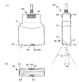
図2は、本実施形態における超音波プローブ50の構成例を示す三面図である。図2(1)が正面図、図2(2)が側面図、図2(3)が下面図すなわち生体4の皮膚面に押し当てる側から見た図である。
FIG. 2 is a three-view diagram illustrating a configuration example of the
本実施形態の超音波プローブ50は、基本的には公知の超音波プローブと同様に実現されるが次の点で異なる特徴を有する。
すなわち、本体ケース51と一体にして、超音波照射する計測面52側に、超音波素子部53と、第1発光部54と、第2発光部56と、受光部57とを備える。また、本体ケース51の上部には、報知部58を備える。本実施形態の超音波計測装置10は、第1発光部54と第2発光部56から照射された計測光の生体4からの反射光を受光部57で受光・計測して超音波計測の対象となる組織の存在を検知し、計測対象組織の存在が検出された旨を報知部58でオペレーターへ報知することができる。
The
That is, an
超音波素子部53は、複数の超音波振動子(超音波トランスデューサー)を列状に配列した素子群、例えば、超音波振動子を1列に配置した公知のリニア型アレイにより実現できる。なお、超音波振動子の並びは、1列に限らず超音波計測の目的に応じて配列数は適宜設定可能である。
The
第1発光部54および第2発光部56は、本体ケース51の下面から下方へ向けて計測光を照射する。より具体的には、計測光の伝搬範囲Arが、超音波素子部53による超音波の計測範囲Asと重なるように第1発光部54および第2発光部56が配置されている。
The first
第1発光部54は、660nm付近の光と赤色可視光を発する発光素子であって、超音波計測の計測対象組織を光学計測で検出するための2種類の計測光のうち一方を照射する。例えば、赤色LED(Light Emitting Diode)により実現されるが、その他の発光素子により実現するとしてもよい。本実施形態の第1発光部54は、超音波素子部53による超音波の発信方向すなわち計測面52の法線方向へ向けて計測光を発するように設けられている。
The first
第2発光部56は、880nm付近の近赤外光を発する発光素子であって、2種類の計測光のうち他方を照射する。例えば、赤外線LEDにより実現されるが、その他の発光素子により実現するとしてもよい。本実施形態の第2発光部56も、超音波素子部53による超音波の発信方向すなわち計測面52の法線方向へ向けて計測光を発するように設けられている。
The 2nd
もし、第1発光部54と第2発光部56の何れか一方が他方に要求される発光特性をも満たすならば、当該他方の発光部を省略し、第1発光部54と第2発光部56とをまとめて1つの発光素子で実現するとしてもよい。
If either one of the first
受光部57は、第1発光部54および第2発光部56から照射された探査光の反射光を受光し、受光強度に応じた信号を出力する素子である。例えば、フォトダイオードなどの光センサーにより実現できる。本実施形態では、計測面52の法線方向からの光を受光可能に設けられている。
The
そして、本実施形態では、第1発光部54および第2発光部56と、受光部57とは、超音波素子列を挟む位置に配置されている。具体的には、第1発光部54と第2発光部56は、超音波素子部53の素子列の左右(図2(3)では上下)の一方側にあたる計測面52の外縁部に互いに近接して設けられている。一方、受光部57は、超音波素子部53の素子列の左右(図2(3)では上下)の他方側にあたる計測面52の外縁部に互いに近接して設けられている。
And in this embodiment, the 1st
なお、計測面52の外縁部には、第1発光部54が発した光が、本体ケース51の側方に漏れるように構造部59が設けられている。構造部59は、本体ケース51に設けた切り欠きや貫通孔、窓によって実現することができる。あるいは、第1発光部54から光を導く導光材を設けることで実現してもよい。勿論、第1発光部54が側面に露出する構成であってもよい。
A
報知部58は、光でオペレーターへ超音波計測装置10の計測に係る状態(計測ステータス)を報知する表示部であって、小型のフラットパネルディスプレイやLEDなどの発光素子により実現される。本実施形態では複数のLEDの配列により構成される。
The
報知部58は、報知パターン(本実施形態では、明滅パターンや色、明暗などの組み合わせからなる発光パターンと言い換えできる)によって、単数又は複数種類の報知を行う。本実施形態における報知は、1)計測対象組織の存在の確からしさ(計測対象組織を検出する水準)を示す指標値の大きさ、すなわち確からしさの程度を発光するLEDの数に置き換えて表示する“組織検出判定中”と、2)計測対象組織が検出されたこと告げる“組織検出”と、3)超音波計測が実施されていることを告げる“超音波計測中”とを含む。
The
なお、報知内容は、これら3つの状態以外にも適宜含めることができる。逆に“組織検出判定中”や“超音波計測中”を省略することもできる。また、本実施形態では光で報知する構成としているが音で報知する構成としてもよい。その場合は、適宜、報知部58にスピーカーを含めるとよい。
The notification content can be included as appropriate in addition to these three states. Conversely, “during tissue detection determination” and “during ultrasonic measurement” may be omitted. Moreover, although it is set as the structure alert | reported with light in this embodiment, it is good also as a structure alert | reported with a sound. In that case, a speaker may be included in the
図3は、第1発光部54および第2発光部56と、受光部57とによる計測対象組織の検出原理について説明する図である。
超音波プローブ50の計測面52を生体4の皮膚に軽く当て、第1発光部54および第2発光部56から計測光を皮下へ向けて照射すると、計測面52の下にある組織に応じた反射光を受光部57で計測することができる。
FIG. 3 is a diagram for explaining the principle of detection of the tissue to be measured by the first
When the
公知の反射型パルスオキシメーターの技術から明らかなように、第1発光部54が照射する赤色光および第2発光部56が照射する近赤外光は、血中のオキシヘモグロビンによる吸光度と、デオキシヘモグロビンによる吸光度とが異なる。また、血管6の吸光度は心臓の拍動により変動・脈動する。
血管6とその周辺組織について着目すれば、血管6による反射光の変動率(受光強度の変動率)は、血管6の周辺組織による反射光の変動率よりも大きいことになる。
つまり、反射光の変動率により、受光部57で受光している反射光が血管6によるものなのか周辺組織によるものであるか、言い換えれば、その時点で超音波プローブ50を当てている位置の皮下に血管6があるか皮下組織があるかを判定することができる。
As is apparent from the known reflection pulse oximeter technology, the red light emitted from the first light-emitting
If attention is paid to the
That is, depending on the variation rate of the reflected light, whether the reflected light received by the
具体的には、赤色光の波形変動幅(Vac)を波形平均電圧(Vdc)で除した赤色反射光変動率(Vac/Vdc)Rと、近赤外光の波形変動幅(Vac)を波形平均電圧(Vdc)で除した近赤外反射光変動率(Vac/Vdc)IRとを算出する。そして、変動率を表す値として“検出判定パラメーター値{(Vac/Vdc)R+(Vac/Vdc)IR}”を算出し、この検出判定パラメーター値を所定の検出判定閾値と比較する。そして、当該閾値以上であれば、血管6の反射光を受光していると判断し、閾値未満であれば血管6の周辺組織による反射光を受光していると判断する。
Specifically, the red reflected light fluctuation rate (Vac / Vdc) R obtained by dividing the waveform fluctuation width (Vac) of the red light by the waveform average voltage (Vdc) and the waveform fluctuation width (Vac) of the near infrared light are waveformd. The near infrared reflected light fluctuation rate (Vac / Vdc) IR divided by the average voltage (Vdc) is calculated. Then, “detection determination parameter value {(Vac / Vdc) R + (Vac / Vdc) IR }” is calculated as a value representing the fluctuation rate, and this detection determination parameter value is compared with a predetermined detection determination threshold value. If it is equal to or greater than the threshold, it is determined that the reflected light of the
ちなみに、公知の反射型パルスオキシメーターでも、赤色光反射変動率(Vac/Vdc)Rと、近赤外反射光変動率(Vac/Vdc)IRとを算出するが、動脈酸素飽和度を求める際には、前者を後者で割った値{(Vac/Vdc)R÷(Vac/Vdc)IR}を用いる。
これに対して、本実施形態では、赤色反射光変動率と近赤外反射光変動率との2種類の変動率の和を血管の検出判定に用いる点が大きく異なる。赤色反射光変動率と近赤外反射光変動率との2種類の変動率の和を用いることにより、公知の反射型パルスオキシメーターをそのまま血管検出に用いる場合よりも、格段に判定精度を高めることが可能となっている。
Incidentally, even with a known reflection type pulse oximeter, the red light reflection fluctuation rate (Vac / Vdc) R and the near infrared reflection light fluctuation rate (Vac / Vdc) IR are calculated. The value obtained by dividing the former by the latter {(Vac / Vdc) R ÷ (Vac / Vdc) IR } is used.
On the other hand, the present embodiment is greatly different in that the sum of the two types of fluctuation rates of the red reflected light fluctuation rate and the near infrared reflected light fluctuation rate is used for blood vessel detection determination. By using the sum of the two types of fluctuation rates of the red reflected light fluctuation rate and the near-infrared reflected light fluctuation rate, the determination accuracy is significantly improved as compared with the case where a known reflection type pulse oximeter is used as it is for blood vessel detection. It is possible.
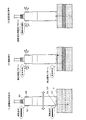
図4は、本実施形態における超音波計測の流れについて説明する図である。
オペレーターが所定の準備操作を実行すると、図4(1)に示すように、超音波計測装置10は第1発光部54と第2発光部56とから計測対象組織検出用に計測光の照射を開始し、更に受光部57による受光結果に基づく検出判定を開始する。また、報知部58をその検出判定に用いる検出判定パラメーター値(計測対象組織の存在の確からしさを示す指標値)の大きさをレベル表示させる。
FIG. 4 is a diagram for explaining the flow of ultrasonic measurement in the present embodiment.
When the operator performs a predetermined preparation operation, as shown in FIG. 4A, the
オペレーターは、構造部59から第1発光部54が発している赤色光や、報知部58の“組織検出判定中”を示す報知パターンにより検出準備が整ったことを理解し、超音波プローブ50を生体4に押し当てる。なお、第1発光部54と第2発光部56の発光開始と合わせて、タッチパネル12にて、計測対象組織があると推測される大凡の位置に超音波プローブ50が当たるように促す表示をするとしてもよい。
The operator understands that the preparation for detection is completed by the red light emitted from the first
オペレーターは、計測対象組織(血管6)を探すように超音波プローブ50を当てる位置を調整する。報知部58のレベル表示が位置調整の頼りとなる。
やがて、図4(2)に示すように、超音波プローブ50が血管6の上に至ると、超音波計測装置10は図3で説明したようにしてこれを検出し、計測ステータスは“組織検出”となる。超音波計測装置10は、第1発光部54と第2発光部56と報知部58とを、検出した旨を報知するための所定検出報知パターン(例えば、1Hzで明滅する発光パターン)で制御する。報知部58については、発光色を制御できるのであれば、所定色に変更するように制御するのもよいであろう。
The operator adjusts the position to which the
Eventually, as shown in FIG. 4B, when the
オペレーターは、第1発光部54や第2発光部56、報知部58の発光パターンが変わったことで、位置調整が完了し、血管が検出されて、超音波計測に適した位置にあることを理解して超音波プローブ50をその位置と姿勢を維持するように努める。
The operator confirms that the light emission patterns of the first light-emitting
計測対象組織が検出されると、続いて図4(3)に示すように、計測ステータスが“超音波計測中”となる。超音波計測装置10は、報知部58を超音波計測の開始を報知する超音波計測報知パターン(例えば、長点灯と短点灯の繰り返し発光パターン)で発光させ、更に自動的に超音波素子部53を用いた超音波計測を開始する。勿論、超音波計測を開始する前に、適宜タッチパネル12にて超音波計測が開始される旨を告げる表示をしてもよい。
When the measurement target tissue is detected, the measurement status subsequently becomes “ultrasonic measurement” as shown in FIG. The
超音波計測は、所定の終了条件を満たすまで継続される。終了条件は、例えば計測時間が所定時間経過したことであったり、オペレーターによる計測終了操作などとすることができる。超音波計測装置10は、終了条件を満たしたことを検出すると、超音波計測を終了し、報知部58を消灯制御する。
The ultrasonic measurement is continued until a predetermined end condition is satisfied. The end condition can be, for example, that the measurement time has elapsed for a predetermined time, or a measurement end operation by the operator. When the
[機能構成の説明]
次に、本実施形態を実現するための機能構成について説明する。
図5は、本実施形態の超音波計測装置10の機能構成例を示すブロック図である。超音波計測装置10は、操作入力部100と、送信部102と、受信部104と、計測光照射部110と、受光部112と、報知出力部114と、処理部200と、画像表示部360と、記憶部500とを備える。
[Description of functional configuration]
Next, a functional configuration for realizing the present embodiment will be described.
FIG. 5 is a block diagram illustrating a functional configuration example of the
操作入力部100は、オペレーターによる各種操作入力を受け付け、操作入力に応じた操作入力信号を処理部200へ出力する。ボタンスイッチやレバースイッチ、ダイヤルスイッチ、トラックパッド、マウス、などにより実現できる。図1のタッチパネル12やキーボード14がこれに該当する。
The
送信部102は、パルス電圧に基づいて超音波を照射する。
受信部104は、送信部102によって照射された超音波が生体4の生体内で反射した反射波信号を受信し、電気信号に変換して出力する。図2の超音波素子部53が、送信部102および受信部104に該当する。
The
The receiving
計測光照射部110は、超音波計測の対象となる組織(計測対象組織)の存在を検出するための計測光を、送信部102による超音波照射範囲すなわち超音波計測の測定範囲と重なるように照射する。発光素子や、光学素子、光学フィルターなどにより実現される。図2の第1発光部54および第2発光部56がこれに該当する。
The measurement
受光部112は、計測光の反射光を受光して電気信号に変換し出力する。公知の光センサーや、光学素子、光学フィルターなどにより実現される。図2の受光部57がこれに該当する。
The
報知出力部114は、計測に係る各種進行状況(計測ステータス)を報知する出力をする。例えば、液晶パネルディスプレイ等の画像表示装置や、LED、スピーカー、バイブレーター、などにより実現することができるが、本実施形態では図1のタッチパネル12や図2の報知部58がこれに該当する。
The
処理部200は、例えば、CPUやGPU等のマイクロプロセッサーや、ASIC、ICメモリーなどの電子部品によって実現される。そして、処理部200は、各機能部との間でデータの入出力制御を行い、所定のプログラムや各種データに基づいて各種の演算処理を実行して、血管位置を判定し、生体4の生体情報を算出する。図1の処理装置30および制御基板31がこれに該当する。
The
本実施形態では、処理部200は、超音波計測制御部210と、検出制御部220と、報知制御部240と、生体情報算出部250と、画像生成部260とを有する。
In the present embodiment, the
超音波計測制御部210は、照射制御部212と、送受信制御部214と、受信合成部216とを有し、超音波計測を統合的に制御する。本実施形態でのサンプリングレートは20回/秒以上のサンプリング速度とし、その一例として20fpsで測定するものとする。
The ultrasonic
照射制御部212は、超音波プローブ50から発信する超音波パルスのタイミングを制御し、送信制御信号を送受信制御部214へ出力する。
The
送受信制御部214は、照射制御部212からの送信制御信号に従ってパルス電圧を発生させて送信部102へ出力する。その際、送信遅延処理を行って各超音波振動子へのパルス電圧の出力タイミングの調整を行うことができる。また、送受信制御部214は、受信部104から出力された反射波信号の増幅やフィルター処理を行って、その結果を受信合成部216へ出力することができる。
The transmission /
受信合成部216は、必要に応じて遅延処理等を行っていわゆる受信信号のフォーカスに係る処理等を実行して反射波信号を生成する。
The
検出制御部220は、光学計測により超音波計測の対象とする組織の検出に係る制御を行う。本実施形態では、計測光照射部110の発光を制御する計測光発光制御部222と、受光部112からの出力信号を受信して光学計測に係る各種パラメーター値を算出し計測対象組織を検出する検出判定部224とを含む。
The
計測対象組織の存在を検出する光学計測に係る各種パラメーター値は、記憶部500に記憶される。例えば、赤色光波形平均値511と、赤色光波形変動幅512と、赤色反射光変動率513と、近赤外光波形平均値521と、近赤外光波形変動幅522と、近赤外反射光変動率523と、検出判定パラメーター値530と、が算出されて記憶される。
Various parameter values related to optical measurement for detecting the presence of the measurement target tissue are stored in the
報知制御部240は、報知出力部114の出力を制御する。本実施形態では、検出制御部220により計測対象組織の存在が検出された場合に、計測光照射部110や報知出力部114を所定の発光パターンで発光させる制御を行うことができる。
The
生体情報算出部250は、受信合成部216が生成した反射波信号に基づいて、計測対象組織に関する生体情報を算出する。例えば、血管径や、動脈硬化指標値、弾性指標値、血圧、血管年齢、IMT(Intima Media Thickness:血管の内膜中膜複合体厚)などである。算出結果は、記憶部500に生体情報計測結果540として記憶する。なお、生体情報計測結果540には、算出結果の基になった反射波信号のデータも適宜含めることができる。
The biological
画像生成部260は、各種操作画面や、計測対象組織の存在検出に関する画像、超音波計測および生体情報測定の計測結果を表示するための画像、計測ステータスを通知する画像などを生成し画像表示部360へ出力する。
The
画像表示部360は、画像生成部260から入力される画像データを表示する。図1のタッチパネル12がこれに該当する。
The
記憶部500は、ICメモリーやハードディスク、光学ディスクなどの記憶媒体により実現され、各種プログラムや、処理部200の演算過程のデータなどの各種データを記憶する。図1では、処理装置30の制御基板31に搭載されている記憶媒体33がこれに該当する。なお、処理部200と記憶部500の接続は、装置内の内部バス回路による接続に限らず、LAN(Local Area Network)やインターネットなどの通信回線で実現しても良い。その場合、記憶部500は超音波計測装置10とは別の外部記憶装置により実現されるとしてもよい。
The
記憶部500は、計測プログラム501と、反射波信号510と、赤色光波形平均値511と、赤色光波形変動幅512と、赤色反射光変動率513と、近赤外光波形平均値521と、近赤外光波形変動幅522と、近赤外反射光変動率523と、検出判定パラメーター値530と、生体情報計測結果540とを記憶する。
The
処理部200は、計測プログラム501を読み出して実行することにより、超音波計測制御部210や、検出制御部220、報知制御部240、生体情報算出部250、画像生成部260等の機能を実現する。
なお、これらの機能部を電子回路等のハードウェアで実現する場合には、当該機能を実現させるためのプログラムの一部を省略することができる。例えば、検出制御部220をLSI等で実現するならば、検出制御部220の機能を実現させるためのプログラム部分、すなわち検出判定プログラム502を省略できる。
The
When these functional units are realized by hardware such as an electronic circuit, a part of a program for realizing the functions can be omitted. For example, if the
反射波信号510は、超音波計測により得られた反射波信号のデータであって、超音波計測制御部210によってフレーム毎に生成される。例えば、1つの反射波信号510には、超音波振動子の識別情報(Tr)と測定されたフレーム識別情報(fr)とが対応づけて格納される。
The reflected
なお、記憶部500は、これら以外にも、各種フラグ、計時用のカウンター値など、血管位置の判定並びに生体情報の算出に必要なデータを適宜記憶することができる。
In addition to these, the
[処理の流れの説明]
次に、超音波計測装置10の動作について説明する。
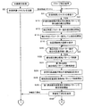
図6は、超音波計測装置10の計測対象組織の存在検出並びに超音波計測に係る処理の流れを説明するためのフローチャートである。
処理部200は、先ず、計測対象組織の検出量の発光パターン(例えば、常時点灯状態)で第1発光部54および第2発光部56の発光を開始する(ステップS10)。そして、受光部57による受光結果に基づいて検出判定パラメーター値530の逐次算出を開始し(ステップS12)、報知部58による検出判定パラメーター値530のレベル表示を開始する(ステップS14)。また、計測対象組織の存在検出の準備が整ったので超音波プローブ50を、皮下に計測対象組織(本実施形態では血管6,より具体的には動脈)が位置していそうな大体の皮膚面位置に当てて、位置調整するようにオペレーターに促す案内画像を生成し、タッチパネル12にて表示させる(ステップS16)。
[Description of process flow]
Next, the operation of the
FIG. 6 is a flowchart for explaining the flow of processing related to the presence detection of the measurement target tissue and the ultrasonic measurement of the
First, the
逐次算出される検出判定パラメーター値530が所定の検出判定閾値に達すると(ステップS20のYES)、処理部200は報知部58を検出報知パターンで制御し(ステップS22)、第1発光部54を検出報知パターンで発光制御する(ステップS24)。そして、タッチパネル12に、計測対象組織が検出された旨を告げる画面を表示させる(ステップS26)。
When the sequentially calculated detection
次いで、処理部200は、報知部58を超音波計測パターンによる制御を開始し(ステップS28)、第1発光部54を超音波計測パターンにより発光させる制御を開始する(ステップS30)。そして、タッチパネル12に超音波計測を開始する旨を告げる画面を表示させる(ステップS44)。
Next, the
そして、処理部200は超音波計測を開始し(ステップS50)。超音波計測結果に基づく生体情報の算出と記録を開始する(ステップS52)。なお、開始前には適宜カウントダウン処理すると好適であろう。また、第1発光部54および第2発光部56からの発光を適宜停止してもよい。
Then, the
超音波計測を開始した後、所定の終了条件を満たしたことを検出すると(ステップS54のYES )、処理部200は計測終了処理を実行し(ステップS60)一連の処理を終了する。
When it is detected that the predetermined end condition is satisfied after starting the ultrasonic measurement (YES in step S54), the
以上、本実施形態によれば、超音波計測の計測対象の位置を検出する補助機能を実現することができる。しかも、補助機能を実現するために従来のような2次元配列型の超音波アレイを必要とせず、第1発光部54と第2発光部56とを用意すれば済むのでより安価に補充機能を実現することができる。計測ステータスの報知についても、構造部59からの漏光で十分とするならば報知部58も省略可能であり、更に安価に補助機能を実現できる。
As described above, according to the present embodiment, it is possible to realize an auxiliary function for detecting the position of a measurement target for ultrasonic measurement. In addition, the conventional two-dimensional array type ultrasonic array is not required to realize the auxiliary function, and the first
また、従来、特に特許文献1の技術では、オペレーターは超音波プローブを操る手元とは別のモニター画面に映し出される超音波画像に注視し、そこから計測対象組織の存在を読み解かねばならず、超音波プローブの位置調整に熟練や集中力が要求された。しかし、本実施形態では、計測対象組織を検出すると超音波プローブで検出を告げる報知が行われるので、オペレーターは超音波プローブを操る手元に注目しさえすれば、超音波画像を読み解く必要もなく、そのための集中力も要求されない。オペレーターの操作負担を大幅に減らすことができる。
Conventionally, in the technique of
なお、本実施形態では、第1発光部54と第2発光部56とからそれぞれ異なる波長の計測光を照射する構成としたが、何れか一方を省略することもできる。
In the present embodiment, the first
また、超音波計測と並行して、あるいは超音波計測とは別に、第1発光部54と第2発光部56と受光部57とを公知の反射型パルスオキシメーターとして機能させることもできる。
In parallel with the ultrasonic measurement or separately from the ultrasonic measurement, the first
〔第2実施形態〕
次に、本発明を適用した第2実施形態について説明する。
本実施形態は、基本的には第1実施形態と同様に実現されるが、計測対象組織の存在を検出するための光学計測に係る制御を、処理装置30ではなく超音波プローブにて行う点が異なる。なお、以降では第1実施形態との差異について主に述べることとし、第1実施形態と同様の構成要素については同じ符号を付与して重複する説明は省略する。
[Second Embodiment]
Next, a second embodiment to which the present invention is applied will be described.
The present embodiment is basically realized in the same manner as the first embodiment, except that the control related to the optical measurement for detecting the presence of the measurement target tissue is performed not by the
図7は、本実施形態における超音波プローブ50Bの構成例を示す三面図である。本実施形態の超音波プローブ50Bは、本体ケース51の内部にプローブ制御基板60を備える。当該基板は、CPU61と、ICメモリー62と、第1発光部54や第2発光部56、報知部58を制御する信号を入出力するインターフェースIC63と、処理装置30とデータ通信するための通信IC64とを搭載する。
FIG. 7 is a trihedral view showing a configuration example of the
CPU61は、ICメモリー62に記憶されているプログラムを読み込んで、第1発光部54や第2発光部56、報知部58を制御するための各種演算処理を実行する。
The
図8は、本実施形態における機能構成例示す機能ブロック図である。
本実施形態では、第1実施形態と比べると、検出制御部220と報知制御部240は、処理部200ではなく超音波プローブ50Bのプローブ処理部200P(図7のプローブ制御基板60に該当)に含まれる。
FIG. 8 is a functional block diagram illustrating a functional configuration example according to the present embodiment.
In the present embodiment, as compared with the first embodiment, the
また、プローブ処理部200Pは、プローブ側通信部242(図7の通信IC64に該当)を有し、処理部200の本機側通信部244との間でデータ通信を行う。
The
プローブ処理部200Pは、プローブ記憶部500P(図7のICメモリー62に該当)に記憶されている検出判定プログラム502を読み出して実行することで、検出制御部220および報知制御部240としての機能を実現する。勿論、検出制御部220および報知制御部240をICチップ等のハードウェアで実現する場合には、この限りではない。
The
図9〜図10は、本実施形態における超音波計測装置10の計測対象組織の存在検出並びに超音波計測に係る処理の流れを説明するためのフローチャートである。
本実施形態の処理の流れは、基本的には第1実施形態と同様であるが、次の点が異なる。すなわち、処理部200が計測準備リクエストをプローブ処理部200Pへ送信すると(ステップS2)、プローブ処理部200Pは当該リクエストを受信して(ステップS4のYES)、ステップS10〜ステップS30を実行し、準備完了報知を処理部200へ送信する(ステップS40)。
9 to 10 are flowcharts for explaining the flow of processing related to the presence detection of the measurement target tissue and the ultrasonic measurement of the
The processing flow of this embodiment is basically the same as that of the first embodiment, but the following points are different. That is, when the
図10のフローチャートに移って、準備完了報知を受信すると(ステップS42のYES)、処理部200はステップS44〜ステップS54を実行する。そして、終了条件を満たすと(ステップS54のYES)、計測完了報知をプローブ処理部200Pへ送信して(ステップS56)、計測終了処理を実行する(ステップS60)。
Moving to the flowchart of FIG. 10, when the preparation completion notification is received (YES in step S42), the
一方、プローブ処理部200Pは、終了報知を受信すると(ステップS62のYES)、第1発光部54や第2発光部56の発光の停止、並びに報知部58での報知を終了するなどの計測終了処理を実行する(ステップS64)。
On the other hand, when the
〔変形例〕
以上、本発明を適用した実施形態について説明したが、上記実施形態に限るものではなく適宜構成要素の追加・省略・変更を施すことができる。
[Modification]
As described above, the embodiment to which the present invention is applied has been described. However, the present invention is not limited to the above-described embodiment, and components can be added, omitted, or changed as appropriate.
例えば、上記実施形態では報知部58を独立して設けているが、これを省略し、第1発光部54の発光パターンの制御と構造部59とで計測ステータスの報知機能をまかなう構成としてもよい。
For example, although the
例えば、図11に示す超音波プローブ50Cのように、第1発光部54と第2発光部56と受光部57とを、超音波素子部53の配列の一方側に寄せて設ける構成も可能である。また、第1実施形態又は第2実施形態の構造部59に代えて、第1発光部54からの光を導き適当に拡散放光する導光材59Cを設けるとしてもよい。
For example, a configuration in which the first
また、超音波プローブ50〜50Cの形状もスティック状に限らず、図12に示す超音波プローブ50Dのように、生体4の皮膚面にジェル等で貼り付け可能なシート状あるいは板状とすることもできる。この構成の場合、本体ケース51の上面(オペレーター側の面)に、超音波素子部53の配列を示す配列方向マーカー71と、第1発光部54および第2発光部56と、受光部57とを結ぶ方向を示す光学計測方向マーカー72を設けると好適である。配列方向マーカー71や光学計測方向マーカー72をLEDなどで実現し、報知部58として機能させるとしてもよい。
Moreover, the shape of the
4…生体、6…血管、10…超音波計測装置、12…タッチパネル、14…キーボード、30…処理装置、31…制御基板、32…CPU、33…記憶媒体、34…通信IC、50…超音波プローブ、51…本体ケース、52…計測面、53…超音波素子部、54…第1発光部、56…第2発光部、57…受光部、58…報知部、59…構造部、59C…導光材、60…プローブ制御基板、62…ICメモリー、63…インターフェースIC、64…通信IC、71…配列方向マーカー、72…光学計測方向マーカー、100…操作入力部、102…送信部、104…受信部、110…計測光照射部、112…受光部、114…報知出力部、200…処理部、200P…プローブ処理部、210…超音波計測制御部、212…照射制御部、214…送受信制御部、216…受信合成部、220…検出制御部、222…計測光発光制御部、224…検出判定部、240…報知制御部、242…プローブ側通信部、244…本機側通信部、250…生体情報算出部、260…画像生成部、360…画像表示部、500…記憶部、500P…プローブ記憶部、501…計測プログラム、502…検出判定プログラム、510…反射波信号、511…赤色光波形平均値、512…赤色光波形変動幅、513…赤色反射光変動率、521…近赤外光波形平均値、522…近赤外光波形変動幅、523…近赤外反射光変動率、530…検出判定パラメーター値、540…生体情報計測結果
4 ... Living body, 6 ... Blood vessel, 10 ... Ultrasonic measuring device, 12 ... Touch panel, 14 ... Keyboard, 30 ... Processing device, 31 ... Control board, 32 ... CPU, 33 ... Storage medium, 34 ... Communication IC, 50 ... Super Sonic probe, 51 ... main body case, 52 ... measurement surface, 53 ... ultrasonic element part, 54 ... first light emitting part, 56 ... second light emitting part, 57 ... light receiving part, 58 ... notification part, 59 ... structure part, 59C DESCRIPTION OF SYMBOLS ... Light guide material, 60 ... Probe control board, 62 ... IC memory, 63 ... Interface IC, 64 ... Communication IC, 71 ... Arrangement direction marker, 72 ... Optical measurement direction marker, 100 ... Operation input part, 102 ... Transmission part, DESCRIPTION OF
Claims (8)
光学計測によって前記計測対象組織を検出するための計測光の生体内の伝搬範囲が前記超音波素子部の測定範囲と重なるように設けられた前記計測光の発光部および受光部と、
を備えた超音波プローブ。 An ultrasonic element unit for ultrasonic measurement of a measurement target tissue in a living body;
A measurement light emitting unit and a light receiving unit provided so that a propagation range of the measurement light for detecting the measurement target tissue by optical measurement overlaps the measurement range of the ultrasonic element unit;
Ultrasonic probe equipped with.
前記発光部と受光部との間に、前記超音波素子列が配置された、
請求項1に記載の超音波プローブ。 The ultrasonic element section has an ultrasonic element array,
The ultrasonic element array is disposed between the light emitting unit and the light receiving unit,
The ultrasonic probe according to claim 1.
前記発光部の発光パターンが制御されることで前記報知がなされる請求項3に記載の超音波プローブ。 The notification unit is a structure that leaks or guides light from the light emitting unit to the side of the ultrasonic probe,
The ultrasonic probe according to claim 3, wherein the notification is made by controlling a light emission pattern of the light emitting unit.
請求項1〜4の何れか一項に記載の超音波プローブ。 The measurement target tissue is a blood vessel,
The ultrasonic probe as described in any one of Claims 1-4.
前記発光部および受光部を制御して前記光学計測を行い、前記計測対象組織を検出する検出制御部と、
を備えた超音波計測装置。 The ultrasonic probe according to any one of claims 1 to 5,
A detection control unit that controls the light emitting unit and the light receiving unit to perform the optical measurement and detects the measurement target tissue;
Ultrasonic measuring device with
前記発光部および受光部を制御して前記光学計測を行い、前記計測対象組織を検出する検出制御部と、
前記検出制御部により検出された場合に、所定の発光パターンで前記発光部を発光させる報知制御部と、
を備えた超音波計測装置。 The ultrasonic probe according to claim 4,
A detection control unit that controls the light emitting unit and the light receiving unit to perform the optical measurement and detects the measurement target tissue;
A notification control unit that, when detected by the detection control unit, causes the light emitting unit to emit light in a predetermined light emission pattern;
Ultrasonic measuring device with
前記発光部および受光部を制御して前記光学計測を行い、前記計測対象組織を検出する水準を示す指標値を算出して、当該計測対象組織を検出する検出制御部と、
前記検出制御部により算出された指標値に応じて前記報知部を表示制御する報知制御部と、
を備えた超音波計測装置。 The ultrasonic probe according to claim 3, wherein the notification unit is a display unit;
A detection control unit that controls the light emitting unit and the light receiving unit to perform the optical measurement, calculates an index value indicating a level for detecting the measurement target tissue, and detects the measurement target tissue;
A notification control unit that controls display of the notification unit according to an index value calculated by the detection control unit;
Ultrasonic measuring device with
Priority Applications (3)
| Application Number | Priority Date | Filing Date | Title |
|---|---|---|---|
| JP2013229058A JP2015089383A (en) | 2013-11-05 | 2013-11-05 | Ultrasonic probe and ultrasonic measuring apparatus |
| CN201410558118.6A CN104605887A (en) | 2013-11-05 | 2014-10-20 | Ultrasonic probe and ultrasonic measuring device |
| US14/523,063 US20150126865A1 (en) | 2013-11-05 | 2014-10-24 | Ultrasonic probe and ultrasonic measuring device |
Applications Claiming Priority (1)
| Application Number | Priority Date | Filing Date | Title |
|---|---|---|---|
| JP2013229058A JP2015089383A (en) | 2013-11-05 | 2013-11-05 | Ultrasonic probe and ultrasonic measuring apparatus |
Publications (2)
| Publication Number | Publication Date |
|---|---|
| JP2015089383A true JP2015089383A (en) | 2015-05-11 |
| JP2015089383A5 JP2015089383A5 (en) | 2016-12-01 |
Family
ID=53007533
Family Applications (1)
| Application Number | Title | Priority Date | Filing Date |
|---|---|---|---|
| JP2013229058A Withdrawn JP2015089383A (en) | 2013-11-05 | 2013-11-05 | Ultrasonic probe and ultrasonic measuring apparatus |
Country Status (3)
| Country | Link |
|---|---|
| US (1) | US20150126865A1 (en) |
| JP (1) | JP2015089383A (en) |
| CN (1) | CN104605887A (en) |
Cited By (2)
| Publication number | Priority date | Publication date | Assignee | Title |
|---|---|---|---|---|
| KR20200049241A (en) * | 2018-10-31 | 2020-05-08 | (주)클래시스 | Ultrasound apparatus for treating brain disease |
| KR20200085694A (en) * | 2020-07-02 | 2020-07-15 | (주)클래시스 | Ultrasound apparatus for treating brain disease |
Families Citing this family (11)
| Publication number | Priority date | Publication date | Assignee | Title |
|---|---|---|---|---|
| US20170124701A1 (en) * | 2014-03-17 | 2017-05-04 | Arizona Board Of Regents On Behalf Of Arizona State University | System and method for measuring artery thickness using ultrasound imaging |
| CN105434047A (en) * | 2015-11-19 | 2016-03-30 | 郑州大学 | Ultrasonic locating method and device for intervention catheter |
| CN105919554A (en) * | 2016-04-15 | 2016-09-07 | 南京航空航天大学 | Ultrasonic near infrared combined detection probe |
| US11612351B2 (en) * | 2016-04-27 | 2023-03-28 | Neux Technologies, Inc. | Electrotherapeutic treatment |
| US20180092631A1 (en) * | 2016-10-03 | 2018-04-05 | National Kaohsiung University Of Applied Sciences | Blood Vessel Analysis Device and Operating Method Thereof |
| US11759168B2 (en) * | 2017-11-14 | 2023-09-19 | Koninklijke Philips N.V. | Ultrasound vascular navigation devices and methods |
| JP6483910B1 (en) * | 2018-11-28 | 2019-03-13 | メロディ・インターナショナル株式会社 | Ultrasonic inspection equipment |
| US11896425B2 (en) | 2021-04-23 | 2024-02-13 | Fujifilm Sonosite, Inc. | Guiding instrument insertion |
| US11900593B2 (en) | 2021-04-23 | 2024-02-13 | Fujifilm Sonosite, Inc. | Identifying blood vessels in ultrasound images |
| US20220361840A1 (en) * | 2021-04-23 | 2022-11-17 | Fujifilm Sonosite, Inc. | Displaying blood vessels in ultrasound images |
| EP4123660A1 (en) * | 2021-07-23 | 2023-01-25 | Siemens Healthcare GmbH | Communication system and method for a medical imaging system |
Citations (7)
| Publication number | Priority date | Publication date | Assignee | Title |
|---|---|---|---|---|
| JP2006346164A (en) * | 2005-06-16 | 2006-12-28 | Seiko Instruments Inc | Measuring device for hemorheology |
| US20070093698A1 (en) * | 2005-10-20 | 2007-04-26 | Glucon Inc. | Apparatus and methods for attaching a device to a body |
| JP2008200155A (en) * | 2007-02-19 | 2008-09-04 | Nippon Dempa Kogyo Co Ltd | Ultrasonic probe |
| US20080287824A1 (en) * | 2007-05-17 | 2008-11-20 | Immersion Medical, Inc. | Systems and Methods for Locating A Blood Vessel |
| JP2008302095A (en) * | 2007-06-11 | 2008-12-18 | Hitachi Ltd | Apparatus for measuring and evaluating blood flow |
| JP2009521973A (en) * | 2006-01-03 | 2009-06-11 | コーニンクレッカ フィリップス エレクトロニクス エヌ ヴィ | Method and system for locating blood vessels |
| JP2010063647A (en) * | 2008-09-11 | 2010-03-25 | Fujifilm Corp | Ultrasonic probe and ultrasonic diagnostic apparatus using the same |
Family Cites Families (7)
| Publication number | Priority date | Publication date | Assignee | Title |
|---|---|---|---|---|
| JP4169688B2 (en) * | 2003-12-02 | 2008-10-22 | オリンパス株式会社 | Human interface device |
| CN1953701A (en) * | 2004-03-11 | 2007-04-25 | 通用医院有限公司 | Method and system for tomographic imaging using fluorescent proteins |
| JP2009077931A (en) * | 2007-09-26 | 2009-04-16 | Toshiba Corp | Biological testing device and biological testing method |
| JP4763095B2 (en) * | 2009-06-08 | 2011-08-31 | オリンパスメディカルシステムズ株式会社 | Biological observation device |
| CN102811657A (en) * | 2009-12-23 | 2012-12-05 | 德尔塔丹麦光电声学公司 | A Monitoring Device |
| CN103054612B (en) * | 2012-12-10 | 2015-06-10 | 苏州佳世达电通有限公司 | Ultrasonic probe mouse and ultrasonoscope |
| TWM458203U (en) * | 2012-12-17 | 2013-08-01 | Ind Tech Res Inst | Photoacoustic detector, photoacoustic board and dector using the photoacoustic board |
-
2013
- 2013-11-05 JP JP2013229058A patent/JP2015089383A/en not_active Withdrawn
-
2014
- 2014-10-20 CN CN201410558118.6A patent/CN104605887A/en active Pending
- 2014-10-24 US US14/523,063 patent/US20150126865A1/en not_active Abandoned
Patent Citations (7)
| Publication number | Priority date | Publication date | Assignee | Title |
|---|---|---|---|---|
| JP2006346164A (en) * | 2005-06-16 | 2006-12-28 | Seiko Instruments Inc | Measuring device for hemorheology |
| US20070093698A1 (en) * | 2005-10-20 | 2007-04-26 | Glucon Inc. | Apparatus and methods for attaching a device to a body |
| JP2009521973A (en) * | 2006-01-03 | 2009-06-11 | コーニンクレッカ フィリップス エレクトロニクス エヌ ヴィ | Method and system for locating blood vessels |
| JP2008200155A (en) * | 2007-02-19 | 2008-09-04 | Nippon Dempa Kogyo Co Ltd | Ultrasonic probe |
| US20080287824A1 (en) * | 2007-05-17 | 2008-11-20 | Immersion Medical, Inc. | Systems and Methods for Locating A Blood Vessel |
| JP2008302095A (en) * | 2007-06-11 | 2008-12-18 | Hitachi Ltd | Apparatus for measuring and evaluating blood flow |
| JP2010063647A (en) * | 2008-09-11 | 2010-03-25 | Fujifilm Corp | Ultrasonic probe and ultrasonic diagnostic apparatus using the same |
Cited By (4)
| Publication number | Priority date | Publication date | Assignee | Title |
|---|---|---|---|---|
| KR20200049241A (en) * | 2018-10-31 | 2020-05-08 | (주)클래시스 | Ultrasound apparatus for treating brain disease |
| KR102148854B1 (en) | 2018-10-31 | 2020-08-28 | (주)클래시스 | Ultrasound apparatus for treating brain disease |
| KR20200085694A (en) * | 2020-07-02 | 2020-07-15 | (주)클래시스 | Ultrasound apparatus for treating brain disease |
| KR102148853B1 (en) | 2020-07-02 | 2020-08-28 | (주)클래시스 | Ultrasound apparatus for treating brain disease |
Also Published As
| Publication number | Publication date |
|---|---|
| CN104605887A (en) | 2015-05-13 |
| US20150126865A1 (en) | 2015-05-07 |
Similar Documents
| Publication | Publication Date | Title |
|---|---|---|
| JP2015089383A (en) | Ultrasonic probe and ultrasonic measuring apparatus | |
| JP4104456B2 (en) | Photoacoustic investigation and imaging system | |
| US9737218B2 (en) | Blood pressure measurement device, electronic device, and blood pressure measurement method | |
| US9179889B2 (en) | Ultrasonic diagnostic device, and method for measuring initma-media complex thickness | |
| JPWO2009013871A1 (en) | Ultrasonic diagnostic equipment | |
| US20140187903A1 (en) | Object information acquiring apparatus | |
| JP2016146958A (en) | Blood pressure measuring device and blood pressure measuring method | |
| US9027412B2 (en) | Method and system for non-invasively monitoring fluid flow in a subject | |
| US20130184544A1 (en) | Body-mounted photoacoustic sensor unit for subject monitoring | |
| US8336391B2 (en) | Method and system for non-invasively monitoring fluid flow in a subject | |
| CA2827981A1 (en) | Regional saturation determination using photoacoustic technique | |
| CN108472012A (en) | Multidigit point continuous ultrasound flow measurement for Hemodynamics management | |
| JP2017153874A (en) | Biological information measurement device and biological information measurement method | |
| CN109069121A (en) | Positioning support and fetal heart frequency registration for CTG ultrasonic transducer are supported | |
| JP5662700B2 (en) | Biological light measurement device and biological light measurement method | |
| KR20100048359A (en) | Ultrasound system for providing ultrasound image with additional information | |
| JP3820162B2 (en) | Cardiodynamic measurement device | |
| US20170303863A1 (en) | Object information obtaining apparatus and control method thereof | |
| WO2010004554A1 (en) | Method and system for non-invasively monitoring fluid flow in a subject | |
| JP6221653B2 (en) | Auxiliary tool and ultrasonic measuring device | |
| CN116269203A (en) | Laser energy correction method and prompting method in photoacoustic imaging system and photoacoustic imaging system | |
| JP2015173922A (en) | Ultrasonic diagnostic device and ultrasonic diagnostic device controlling method | |
| JP2017070317A (en) | Ultrasound diagnostic device and pulse wave measurement method | |
| US9737283B2 (en) | Ultrasound measurement apparatus and ultrasound measurement method | |
| US11406294B2 (en) | System and method for improved monitoring of a sample |
Legal Events
| Date | Code | Title | Description |
|---|---|---|---|
| RD04 | Notification of resignation of power of attorney |
Free format text: JAPANESE INTERMEDIATE CODE: A7424 Effective date: 20160617 |
|
| RD03 | Notification of appointment of power of attorney |
Free format text: JAPANESE INTERMEDIATE CODE: A7423 Effective date: 20160627 |
|
| A521 | Request for written amendment filed |
Free format text: JAPANESE INTERMEDIATE CODE: A523 Effective date: 20161012 |
|
| A621 | Written request for application examination |
Free format text: JAPANESE INTERMEDIATE CODE: A621 Effective date: 20161012 |
|
| A977 | Report on retrieval |
Free format text: JAPANESE INTERMEDIATE CODE: A971007 Effective date: 20170630 |
|
| A131 | Notification of reasons for refusal |
Free format text: JAPANESE INTERMEDIATE CODE: A131 Effective date: 20170808 |
|
| A761 | Written withdrawal of application |
Free format text: JAPANESE INTERMEDIATE CODE: A761 Effective date: 20170831 |