JP2015039522A - Rehabilitation device and assistive device for phantom limb pain treatment - Google Patents
Rehabilitation device and assistive device for phantom limb pain treatment Download PDFInfo
- Publication number
- JP2015039522A JP2015039522A JP2013172039A JP2013172039A JP2015039522A JP 2015039522 A JP2015039522 A JP 2015039522A JP 2013172039 A JP2013172039 A JP 2013172039A JP 2013172039 A JP2013172039 A JP 2013172039A JP 2015039522 A JP2015039522 A JP 2015039522A
- Authority
- JP
- Japan
- Prior art keywords
- image
- body part
- mark
- hand
- paralyzed
- Prior art date
- Legal status (The legal status is an assumption and is not a legal conclusion. Google has not performed a legal analysis and makes no representation as to the accuracy of the status listed.)
- Withdrawn
Links
Images


Classifications
-
- G—PHYSICS
- G09—EDUCATION; CRYPTOGRAPHY; DISPLAY; ADVERTISING; SEALS
- G09B—EDUCATIONAL OR DEMONSTRATION APPLIANCES; APPLIANCES FOR TEACHING, OR COMMUNICATING WITH, THE BLIND, DEAF OR MUTE; MODELS; PLANETARIA; GLOBES; MAPS; DIAGRAMS
- G09B19/00—Teaching not covered by other main groups of this subclass
-
- G—PHYSICS
- G06—COMPUTING; CALCULATING OR COUNTING
- G06T—IMAGE DATA PROCESSING OR GENERATION, IN GENERAL
- G06T11/00—2D [Two Dimensional] image generation
-
- G—PHYSICS
- G06—COMPUTING; CALCULATING OR COUNTING
- G06T—IMAGE DATA PROCESSING OR GENERATION, IN GENERAL
- G06T7/00—Image analysis
- G06T7/70—Determining position or orientation of objects or cameras
- G06T7/73—Determining position or orientation of objects or cameras using feature-based methods
-
- G—PHYSICS
- G16—INFORMATION AND COMMUNICATION TECHNOLOGY [ICT] SPECIALLY ADAPTED FOR SPECIFIC APPLICATION FIELDS
- G16H—HEALTHCARE INFORMATICS, i.e. INFORMATION AND COMMUNICATION TECHNOLOGY [ICT] SPECIALLY ADAPTED FOR THE HANDLING OR PROCESSING OF MEDICAL OR HEALTHCARE DATA
- G16H20/00—ICT specially adapted for therapies or health-improving plans, e.g. for handling prescriptions, for steering therapy or for monitoring patient compliance
- G16H20/30—ICT specially adapted for therapies or health-improving plans, e.g. for handling prescriptions, for steering therapy or for monitoring patient compliance relating to physical therapies or activities, e.g. physiotherapy, acupressure or exercising
-
- G—PHYSICS
- G16—INFORMATION AND COMMUNICATION TECHNOLOGY [ICT] SPECIALLY ADAPTED FOR SPECIFIC APPLICATION FIELDS
- G16H—HEALTHCARE INFORMATICS, i.e. INFORMATION AND COMMUNICATION TECHNOLOGY [ICT] SPECIALLY ADAPTED FOR THE HANDLING OR PROCESSING OF MEDICAL OR HEALTHCARE DATA
- G16H30/00—ICT specially adapted for the handling or processing of medical images
- G16H30/40—ICT specially adapted for the handling or processing of medical images for processing medical images, e.g. editing
-
- A—HUMAN NECESSITIES
- A61—MEDICAL OR VETERINARY SCIENCE; HYGIENE
- A61F—FILTERS IMPLANTABLE INTO BLOOD VESSELS; PROSTHESES; DEVICES PROVIDING PATENCY TO, OR PREVENTING COLLAPSING OF, TUBULAR STRUCTURES OF THE BODY, e.g. STENTS; ORTHOPAEDIC, NURSING OR CONTRACEPTIVE DEVICES; FOMENTATION; TREATMENT OR PROTECTION OF EYES OR EARS; BANDAGES, DRESSINGS OR ABSORBENT PADS; FIRST-AID KITS
- A61F2/00—Filters implantable into blood vessels; Prostheses, i.e. artificial substitutes or replacements for parts of the body; Appliances for connecting them with the body; Devices providing patency to, or preventing collapsing of, tubular structures of the body, e.g. stents
- A61F2/50—Prostheses not implantable in the body
- A61F2002/5058—Prostheses not implantable in the body having means for restoring the perception of senses
- A61F2002/5064—Prostheses not implantable in the body having means for restoring the perception of senses for reducing pain from phantom limbs
-
- G—PHYSICS
- G06—COMPUTING; CALCULATING OR COUNTING
- G06T—IMAGE DATA PROCESSING OR GENERATION, IN GENERAL
- G06T2207/00—Indexing scheme for image analysis or image enhancement
- G06T2207/30—Subject of image; Context of image processing
- G06T2207/30004—Biomedical image processing
-
- G—PHYSICS
- G06—COMPUTING; CALCULATING OR COUNTING
- G06T—IMAGE DATA PROCESSING OR GENERATION, IN GENERAL
- G06T2207/00—Indexing scheme for image analysis or image enhancement
- G06T2207/30—Subject of image; Context of image processing
- G06T2207/30196—Human being; Person
-
- G—PHYSICS
- G06—COMPUTING; CALCULATING OR COUNTING
- G06T—IMAGE DATA PROCESSING OR GENERATION, IN GENERAL
- G06T2207/00—Indexing scheme for image analysis or image enhancement
- G06T2207/30—Subject of image; Context of image processing
- G06T2207/30204—Marker
-
- G—PHYSICS
- G06—COMPUTING; CALCULATING OR COUNTING
- G06T—IMAGE DATA PROCESSING OR GENERATION, IN GENERAL
- G06T2210/00—Indexing scheme for image generation or computer graphics
- G06T2210/41—Medical
-
- G—PHYSICS
- G06—COMPUTING; CALCULATING OR COUNTING
- G06T—IMAGE DATA PROCESSING OR GENERATION, IN GENERAL
- G06T2215/00—Indexing scheme for image rendering
- G06T2215/16—Using real world measurements to influence rendering
Landscapes
- Engineering & Computer Science (AREA)
- Health & Medical Sciences (AREA)
- General Physics & Mathematics (AREA)
- Theoretical Computer Science (AREA)
- Physics & Mathematics (AREA)
- Business, Economics & Management (AREA)
- Epidemiology (AREA)
- Public Health (AREA)
- Primary Health Care (AREA)
- Medical Informatics (AREA)
- General Health & Medical Sciences (AREA)
- Entrepreneurship & Innovation (AREA)
- Educational Technology (AREA)
- Educational Administration (AREA)
- Physical Education & Sports Medicine (AREA)
- Biophysics (AREA)
- Life Sciences & Earth Sciences (AREA)
- Nuclear Medicine, Radiotherapy & Molecular Imaging (AREA)
- Radiology & Medical Imaging (AREA)
- Computer Vision & Pattern Recognition (AREA)
- Rehabilitation Tools (AREA)
Abstract
Description
本発明は、リハビリ装置および幻肢痛治療支援装置に関するものである。 The present invention relates to a rehabilitation apparatus and a phantom limb pain treatment support apparatus.
脳卒中により脳内の神経回路が損傷を受けたとき、手足が動かせなくなることがある。このような患者がリハビリを行う方法が考案されている。その1つに、麻痺した手足を動かすように患者に考えさせるとともに、麻痺した手足が動く画像を見せて手足が動いていると患者に錯覚させる方法がある。 When a neural circuit in the brain is damaged by a stroke, the limbs may become unable to move. Methods have been devised for such patients to rehabilitate. One of them is a method of making a patient think about moving a paralyzed limb, and showing the image of the paralyzed limb moving and causing the patient to have an illusion that the limb is moving.
事故等により手足が欠損した患者に手足が痛む感覚が生じることがある。この現象を幻肢痛という。このような患者においても同様な方法が有効であることが解明されている。欠損した手足が実在するように錯覚させる画像を患者にみせる方法である。この方法により、患者の脳内では欠損した手足の認識が適切に行われて、痛みが消える、または緩和される。 A patient with limb loss due to an accident or the like may experience a sensation of limb pain. This phenomenon is called phantom limb pain. It has been elucidated that similar methods are effective in such patients. In this method, the patient is presented with an illusion that the missing limbs exist. By this method, the missing limb is properly recognized in the patient's brain, and the pain disappears or is alleviated.
そして、患者に麻痺した手や欠損した手が動いているように見せる装置が特許文献1に開示されている。それによると、患者の身体に複数の磁気センサーを設置する。そして、患者に所定の磁場を加えて患者の姿勢を検出する。そして、表示装置に手の動画を表示する。このとき、患者と動画の手とが一体となるように動画の手の位置、姿勢、大きさを調整する。
An apparatus that makes a patient feel as if a paralyzed hand or a deficient hand is moving is disclosed in
患者は動画を見て動画の手が自分の身体の一部であると錯覚する。手が欠損している患者は脳内で手の一体感を再体験することにより手の、痛みが消える、または緩和される。手が麻痺している患者は脳内で神経回路が再構築されるので、手の麻痺が改善される。 The patient sees the video and has the illusion that the hand of the video is part of his body. Patients with deficient hands relieve hand sensation in the brain and the pain in the hands disappears or is relieved. In patients with paralyzed hands, neural circuitry is reconstructed in the brain, improving hand paralysis.
麻痺した身体のリハビリや幻肢痛の治療は複数回行う必要がある。そして、治療を行う頻度を高くすると回復が早くなる。特にリハビリの治療では症状が発症してから早期に行うことが有効である。特許文献1にて開示された装置は大型であり特定の施設に据え置かれた装置となっている。患者は特定の施設に通って順番待ちをした後、装置の操作者とともに治療を行っていた。従って、従来の装置は治療を手軽に行える装置ではなかった。そこで、1人でも治療を行える簡便な装置が望まれていた。
Treatment of paralyzed body rehabilitation and phantom limb pain must be done multiple times. And if the frequency of treatment is increased, recovery is accelerated. In particular, it is effective to perform rehabilitation early after the onset of symptoms. The apparatus disclosed in
本発明は、上述の課題を解決するためになされたものであり、以下の形態または適用例として実現することが可能である。 The present invention has been made to solve the above-described problems, and can be realized as the following forms or application examples.
[適用例1]
本適用例にかかるリハビリ装置は、麻痺した身体部分の機能を回復するリハビリ装置であって、前記麻痺した身体部分に設置されたマークを撮影し撮影画像を出力する撮影部と、前記撮影画像を入力し前記マークの画像を用いて前記麻痺した身体部分の位置を認識する認識部と、前記麻痺した身体部分が動く動画を出力する画像形成部と、前記麻痺した身体部分に重ねて前記動画を表示する表示部と、を備えることを特徴とする。
[Application Example 1]
The rehabilitation device according to this application example is a rehabilitation device that restores the function of the paralyzed body part, and shoots a mark placed on the paralyzed body part and outputs a captured image; and A recognition unit that inputs and recognizes the position of the paralyzed body part using the image of the mark; an image forming unit that outputs a moving image of the paralyzed body part; and the video that is superimposed on the paralyzed body part. And a display unit for displaying.
本適用例によれば、麻痺した身体部分にはマークが設置される。そして、撮影部がマークを撮影して撮影した画像を認識部に出力する。認識部は撮影した画像からマークを抽出する。そして、認識部はマークを用いて麻痺した身体部分の位置を認識する。画像形成部は麻痺した身体部分が動く動画を表示部に出力する。 According to this application example, the mark is placed on the paralyzed body part. Then, the image capturing unit captures the mark and outputs the captured image to the recognition unit. The recognition unit extracts a mark from the photographed image. The recognition unit recognizes the position of the paralyzed body part using the mark. The image forming unit outputs a moving image of the paralyzed body part to the display unit.
患者は脳内で麻痺した身体部分が動くように指示し、麻痺した身体部分が動く動画を見る。このとき、患者の脳内では指示した内容と視覚から受ける情報とが類似した内容となる。つまり、患者には麻痺した身体部分が指示した通りに動作する感覚を得ることができる。そして、患者の脳内では指示情報を麻痺した身体部分に伝達するように神経回路が回復される。 The patient instructs the paralyzed body part to move in the brain, and sees a video of the paralyzed body part moving. At this time, in the patient's brain, the instructed content is similar to the information received from the vision. That is, the patient can have a sense that the paralyzed body part operates as instructed. In the patient's brain, the neural circuit is restored so that the instruction information is transmitted to the paralyzed body part.
本適用例のリハビリ装置では麻痺した身体部分に設置されたマークを用いて撮影部及び認識部が麻痺した身体部分の位置を検出する。これにより、表示部は麻痺した身体部分に重ねて動画を表示することができる。従って、簡便な装置で患者は麻痺した身体部分のリハビリを行うことができる。従来の装置では患者の姿勢を検出するのに大型の装置にて行っていたので、1人で操作することが難しかった。これに比べて本適用例のリハビリ装置は簡便な装置で麻痺した身体部分を認識するので、1人でリハビリ装置を操作してリハビリ治療をすることができる。 In the rehabilitation device of this application example, the imaging unit and the recognition unit detect the position of the paralyzed body part using a mark placed on the paralyzed body part. Thereby, a display part can display a moving image on a paralyzed body part. Therefore, the patient can rehabilitate the paralyzed body part with a simple device. In the conventional apparatus, since a large apparatus is used to detect the posture of the patient, it is difficult to operate by one person. Compared to this, the rehabilitation device of this application example recognizes a paralyzed body part with a simple device, so that one person can operate the rehabilitation device to perform rehabilitation treatment.
[適用例2]
上記適用例にかかるリハビリ装置において、前記認識部は前記マークの画像を用いて前記麻痺した身体部分の姿勢を認識し、前記画像形成部は前記麻痺した身体部分の姿勢と同じ姿勢で動く動画を出力することを特徴とする。
[Application Example 2]
In the rehabilitation apparatus according to the application example, the recognition unit recognizes a posture of the paralyzed body part using the image of the mark, and the image forming unit displays a moving image in the same posture as the posture of the paralyzed body part. It is characterized by outputting.
本適用例によれば、撮影部がマークを撮影する。そして、認識部はマークの画像を用いて麻痺した身体部分の姿勢を認識する。そして、画像形成部は麻痺した身体部分の姿勢と同じ姿勢で動く動画を出力する。従って、表示部は麻痺した身体部分が捻じれているときにも捻じれた身体部分に合わせた画像を表示することができる。 According to this application example, the photographing unit photographs the mark. Then, the recognition unit recognizes the posture of the paralyzed body part using the mark image. Then, the image forming unit outputs a moving image that moves in the same posture as that of the paralyzed body part. Therefore, the display unit can display an image that matches the twisted body part even when the paralyzed body part is twisted.
患者はリハビリ治療を行う場所が麻痺しているので麻痺した身体部分を所定の姿勢に移動することが難しい。本適用例のリハビリ装置は患者の麻痺した身体部分が捻じれているときにも麻痺した身体部分に重ねて動画を表示することができる。従って、患者は容易にリハビリ治療を行うことができる。 Since the place where the rehabilitation treatment is performed is paralyzed, it is difficult for the patient to move the paralyzed body part to a predetermined posture. The rehabilitation device of this application example can display a moving image superimposed on the paralyzed body part even when the paralyzed body part of the patient is twisted. Therefore, the patient can easily perform rehabilitation treatment.
[適用例3]
上記適用例にかかるリハビリ装置において、前記認識部は前記マークの画像を用いて前記マークと前記撮影部との距離を認識し、前記画像形成部は前記麻痺した身体部分が動く動画を前記距離に応じた大きさで出力することを特徴とする。
[Application Example 3]
In the rehabilitation apparatus according to the application example, the recognition unit recognizes a distance between the mark and the photographing unit using the image of the mark, and the image forming unit sets a moving image of the paralyzed body part as the distance. It outputs in the magnitude | size according to it.
本適用例によれば、認識部はマークの画像を用いてマークと撮影部との距離を認識する。マークは撮影部から離れるに従って小さな像となる。マークの撮影画像の大きさからマークと撮影部との距離を認識することができる。そして、距離に応じた大きさの画像を表示する。従って、患者は画像を見て麻痺した身体部分が動く様子を体感することができる。 According to this application example, the recognition unit recognizes the distance between the mark and the photographing unit using the image of the mark. The mark becomes a small image as the distance from the photographing unit increases. The distance between the mark and the photographing unit can be recognized from the size of the photographed image of the mark. Then, an image having a size corresponding to the distance is displayed. Therefore, the patient can experience the movement of the paralyzed body part by looking at the image.
[適用例4]
上記適用例にかかるリハビリ装置において、前記認識部は前記マークの画像を用いて前記麻痺した身体部分が延在する方向を認識し、前記画像形成部は前記麻痺した身体部分が向く方向と同じ方向を向いて動く動画を出力することを特徴とする。
[Application Example 4]
In the rehabilitation apparatus according to the application example, the recognition unit recognizes a direction in which the paralyzed body part extends using an image of the mark, and the image forming unit has the same direction as the direction in which the paralyzed body part faces. It is characterized by outputting a moving video that faces the camera.
本適用例によれば、認識部はマークの画像を用いてマークと麻痺した身体部分が延在する方向を認識する。そして、麻痺した身体部分が延在する方向と同じ方向に身体部分を延在させた画像を表示する。従って、患者は画像を見て麻痺した身体部分が動く様子を体感することができる。 According to this application example, the recognition unit recognizes the direction in which the mark and the paralyzed body part extend using the image of the mark. And the image which extended the body part in the same direction as the direction where the paralyzed body part extends is displayed. Therefore, the patient can experience the movement of the paralyzed body part by looking at the image.
[適用例5]
上記適用例にかかるリハビリ装置において、前記撮影部が有する撮像装置の台数は1台であることを特徴とする。
[Application Example 5]
In the rehabilitation apparatus according to the application example described above, the number of imaging apparatuses included in the imaging unit is one.
本適用例によれば、撮影部が有する撮像装置の台数は1台で構成されている。従って、リハビリ装置は簡便となり製造し易い装置にすることができる。 According to this application example, the number of imaging devices included in the imaging unit is configured as one. Therefore, the rehabilitation apparatus is simple and can be easily manufactured.
[適用例6]
上記適用例にかかるリハビリ装置において、前記マークは前記麻痺した身体部分に複数設置されることを特徴とする。
[Application Example 6]
In the rehabilitation apparatus according to the application example described above, a plurality of the marks are installed on the paralyzed body part.
本適用例によれば、マークは麻痺した身体部分に複数設置される。撮影部から麻痺した身体部分を撮影するとき、麻痺した身体部分は撮影される場所と撮影できない場所とができる。そして、マークは複数設置されているので、少なくとも1つのマークが撮影されることにより麻痺した身体部分の位置を認識部が認識することができる。 According to this application example, a plurality of marks are placed on a paralyzed body part. When a paralyzed body part is imaged from the imaging unit, the paralyzed body part can be taken as a place where it can be taken and where it cannot be taken. Since a plurality of marks are provided, the recognition unit can recognize the position of the paralyzed body part by photographing at least one mark.
[適用例7]
上記適用例にかかるリハビリ装置において、前記画像形成部が出力する前記麻痺した身体部分が動く動画の早さを指示する入力部を備えることを特徴とする。
[Application Example 7]
In the rehabilitation apparatus according to the application example, the rehabilitation apparatus includes an input unit that instructs a speed of a moving image of the paralyzed body part output from the image forming unit.
本適用例によれば、患者は入力部を操作することにより、動画の早さを指示することができる。従って、患者は動画の早さを調整して、画像を見て麻痺した身体部分が動く様子を体感し易くすることができる。 According to this application example, the patient can instruct the speed of the moving image by operating the input unit. Therefore, the patient can adjust the speed of the moving image to make it easier to experience the movement of the paralyzed body part by looking at the image.
[適用例8]
本適用例にかかる幻肢痛治療支援装置は、欠損した身体部分の痛みを軽減させる幻肢痛治療支援装置であって、前記欠損した身体部分に続く身体部分に設置されたマークを撮影する撮影部と、前記マークを用いて前記欠損した身体部分の位置を認識する認識部と、前記欠損した身体部分が動く動画を出力する画像形成部と、前記欠損した身体部分の位置に前記動画を表示する表示部と、を備えることを特徴とする。
[Application Example 8]
The phantom limb pain treatment support apparatus according to this application example is a phantom limb pain treatment support apparatus that reduces pain in a missing body part, and shoots a mark placed on a body part that follows the missing body part. A recognition unit that recognizes the position of the missing body part using the mark, an image forming unit that outputs a moving image of the missing body part, and the moving image is displayed at the position of the missing body part. And a display unit.
本適用例によれば、欠損した身体部分に続く身体部分にはマークが設置される。そして、撮影部がマークを撮影して撮影した画像を認識部に出力する。認識部は撮影した画像からマークを抽出する。そして、認識部はマークを用いて欠損した身体部分の位置を認識する。画像形成部は欠損した身体部分の位置で身体部分が動くような動画を表示部に出力する。 According to this application example, the mark is placed on the body part that follows the missing body part. Then, the image capturing unit captures the mark and outputs the captured image to the recognition unit. The recognition unit extracts a mark from the photographed image. The recognition unit recognizes the position of the missing body part using the mark. The image forming unit outputs to the display unit a moving image in which the body part moves at the position of the missing body part.
患者は欠損した身体部分が動く動画を見る。このとき、患者の脳内では欠損した身体部分が動作する感覚を得る。そして、患者の脳内では欠損した身体部分を正しく認識するように神経回路が構築される。 The patient watches a moving movie of the missing body part. At this time, a sense of movement of the missing body part in the patient's brain is obtained. A neural circuit is constructed to correctly recognize the missing body part in the patient's brain.
本適用例の幻肢痛治療支援装置では欠損した身体部分に続く身体部分に設置されたマークを用いて撮影部及び認識部が欠損した身体部分の位置を検出する。従って、簡便な装置で患者は欠損した身体部分のリハビリを行うことができる。従来の装置では患者の姿勢を検出するのに大型の装置にて行っていたので、1人で操作することが難しかった。これに比べて本適用例の幻肢痛治療支援装置は簡便な装置で欠損した身体部分を認識するので、1人で幻肢痛治療支援装置を操作して幻肢痛治療をすることができる。 In the phantom limb pain treatment support apparatus of this application example, the position of the body part in which the imaging unit and the recognition unit are missing is detected using a mark placed on the body part following the missing body part. Therefore, the patient can rehabilitate the missing body part with a simple device. In the conventional apparatus, since a large apparatus is used to detect the posture of the patient, it is difficult to operate by one person. Compared to this, the phantom limb pain treatment support device of this application example recognizes a missing body part with a simple device, so that one person can operate the phantom limb pain treatment support device to treat phantom limb pain. .
本実施形態では、リハビリ装置と、このリハビリ装置を用いてリハビリを行う方法との特徴的な例について、図に従って説明する。以下、実施形態について図面に従って説明する。尚、各図面における各部材は、各図面上で認識可能な程度の大きさとするため、各部材毎に縮尺を異ならせて図示している。 In this embodiment, a characteristic example of a rehabilitation apparatus and a method for performing rehabilitation using the rehabilitation apparatus will be described with reference to the drawings. Hereinafter, embodiments will be described with reference to the drawings. In addition, each member in each drawing is illustrated with a different scale for each member in order to make the size recognizable on each drawing.
(第1の実施形態)
第1の実施形態にかかわるリハビリ装置について図1〜図5に従って説明する。図1は、リハビリ装置の構成を示すブロック図である。図1に示すように、リハビリ装置1は表示部としてのヘッドマウントディスプレイ2を備え、ヘッドマウントディスプレイ2は患者3の頭部3aに設置されている。ヘッドマウントディスプレイ2は患者3の眼3bと対向する場所に鏡部2aが設置されている。ヘッドマウントディスプレイ2は投影部2bを備え、投影部2bは鏡部2aに光を射出する。光は鏡部2aにて反射して眼3bに入射する。患者3は眼3bに入った光により虚像の動画を観ることができる。ヘッドマウントディスプレイ2は右眼と左眼とにそれぞれ別の映像を見せることが可能になっている。従って、ヘッドマウントディスプレイ2は患者3に立体画像を見せることができる。鏡部2aは非透過型の鏡とする。
(First embodiment)
The rehabilitation apparatus according to the first embodiment will be described with reference to FIGS. FIG. 1 is a block diagram showing the configuration of the rehabilitation apparatus. As shown in FIG. 1, the
ヘッドマウントディスプレイ2には撮影部及び撮像装置としてのカメラ4が設置されている。カメラ4は患者3が見ることができる範囲を撮影することができる。カメラ4は内部に対物レンズ及びCCD(Charge Coupled Device)撮像素子が組み込まれたものである。カメラ4はフォーカスの合う範囲が長い対物レンズを備えている。視界にある物で反射した光をカメラ4は対物レンズを通して入力し、対物レンズを通過した光がCCD撮像素子に結像する。そして、CCD撮像素子が結像した画像を電気信号に変換することにより視界にある物を撮像することが可能となっている。尚、カメラ4はCCD撮像素子に代えて撮像管やCMOS(相補性金属酸化膜半導体)イメージセンサーを用いることができる。他にも赤外線イメージセンサーを用いてもよい。
The head mounted
ヘッドマウントディスプレイ2は通信部2cを備えている。リハビリ装置1は制御装置5を備え、通信部2cは制御装置5と通信しデータを送受信する。通信部2cは電波を媒体とした通信や、光を媒体とした通信等の無線通信や有線での通信の形態でも良い。本実施形態では、例えば、通信部2cはブルートゥース通信を行う装置となっている。
The head mounted
患者3は麻痺した身体部分としての手3cを有し、患者3はリハビリ装置1を用いて手3cの動作を回復する訓練を行う。手3cには複数のマーク6が設置されている。マーク6は所定のパターンの図案が描画された粘着シールである。粘着シールを手3cに貼り付けることによりマーク6を手3cに設置することができる。マーク6は着脱可能となっている。他にも、マーク6は手袋に印刷されても良い。患者3は手袋を手3cに装着することによりマーク6を手3cに設置することができる。
The
カメラ4は麻痺した手3cに設置されたマーク6を撮影し撮影した撮影画像を通信部2cに出力する。通信部2cは撮影画像のデータを制御装置5に送信する。
The camera 4 captures the
制御装置5は入出力インターフェイス7を備え、入出力インターフェイス7には入力部としての入出力端末8、スピーカー9、通信装置10が接続されている。入出力端末8には入力キー8aと表示パネル8bとを備えている。入力キー8aは患者3がリハビリ装置1を操作するときに指示する内容を入力するボタンである。表示パネル8bは制御装置5が患者3に報知するメッセージを表示するときに表示する部位である。例えば、制御装置5は表示パネル8bに操作を促すメッセージを表示し、患者3はメッセージに従って、入力キー8aを操作する。従って、患者3は入出力端末8を操作してリハビリ装置1を操作することができる。
The
スピーカー9は音声信号にて患者3にメッセージを伝える機能を備えている。患者3がリハビリ治療中のとき、患者3が表示パネル8bを見ていないときにも制御装置5はスピーカー9から患者3にメッセージを伝えることができる。
The
通信装置10はヘッドマウントディスプレイ2に設置された通信部2cと通信を行う装置である。通信装置10と通信部2cとはカメラ4が撮影した画像のデータや投影部2bから射出する映像のデータ等を通信する。
The
制御装置5は他にもプロセッサーとして各種の演算処理を行うCPU11(中央演算処理装置)と、各種情報を記憶する記憶部12とを備えている。入出力インターフェイス7及び記憶部12はデータバス13を介してCPU11に接続されている。
In addition, the
記憶部12は、RAM、ROM等といった半導体メモリーや、ハードディスク、DVD−ROMといった外部記憶装置を含む概念である。機能的には、投影部2bが投影する画像データ14を記憶するための記憶領域が設定される。画像データ14にはカメラ4が撮影した画像のデータも含まれる。他にも、マーク6の形状やマーク6が設置された場所等のマーク情報15を記憶するための記憶領域が設定される。他にも、リハビリ装置1の動作の制御手順が記述されたプログラムソフト16を記憶する記憶領域が設定される。他にも、CPU11のためのワークエリアやテンポラリーファイル等として機能する記憶領域やその他各種の記憶領域が設定される。
The
CPU11は、記憶部12内に記憶されたプログラムソフト16に従って、リハビリ装置1の制御を行うものである。具体的な機能実現部として認識部としての位置認識部17を有する。位置認識部17は撮影画像を入力する。位置認識部17はマーク6の撮影画像を用いて麻痺した手3cの位置を認識する。具体的には、ヘッドマウントディスプレイ2とマーク6との距離や相対位置を演算する。そして、位置認識部17は演算した結果をマーク情報15として記憶部12に記憶する。
The
他にも、CPU11は画像形成部18を有する。画像形成部18は麻痺した手3cが動く立体画像の動画を演算して出力する。記憶部12には手3cの指が動いて掌を開閉する動画の画像データ14が記憶されている。そして、マーク情報15にはカメラ4が撮影した撮影画像を用いて演算した手3cの姿勢及び位置の情報が記憶されている。画像形成部18は手3cの指が動く動画を座標変換する機能を備えている。そして、画像形成部18は患者3から見た手3cの姿勢と動画における手の姿勢とが同じになるように変換する。次に、画像形成部18は変換した動画のデータを画像データ14として記憶部12に記憶する。
In addition, the
他にも、CPU11は画像送信部19を有する。画像送信部19は画像データ14の動画のデータをヘッドマウントディスプレイ2に転送する機能を有する。ヘッドマウントディスプレイ2は所定の表示時間の動画のデータを記憶するメモリーを備えている。そして、画像送信部19は動画のデータをヘッドマウントディスプレイ2のメモリーへ転送する。ヘッドマウントディスプレイ2ではメモリーに転送された画像データを用いて投影部2bが動画を投影する。
In addition, the
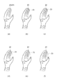
図2は、手に設置されたマークを説明するための模式図である。図2(a)は、手3cの掌側にマーク6が設置されている様子を示し、図2(b)は、手3cの甲側にマーク6が設置されている様子を示している。図2(c)は、マーク6の図案を示している。
FIG. 2 is a schematic diagram for explaining a mark placed on a hand. FIG. 2A shows a state in which the
図2(a)及び図2(b)に示すように、手3cには複数のマーク6が設置されている。手首3dには4つのマーク6が設置されている。手首3dの掌側、手の甲側、親指側、小指側にマーク6が設置されている。手首3dを回転したとき4つのマーク6のうち1つか2つがカメラ4の方を向く。従って、患者3が手首3dを回転してもカメラ4はマーク6を撮影することができる。
As shown in FIGS. 2A and 2B, a plurality of
さらに、手3cにおいても掌、手の甲、親指のつけね側、小指のつけね側にマーク6が設置されている。従って、患者3が手首3dを回転してもカメラ4はいずれかのマーク6を撮影することができる。手首3dに設置されたマーク6と手3cに設置されたマーク6とを比較することにより手首の関節が曲がっている状態か真直ぐの状態かを認識することができる。
Further, in the
図2(c)に示すように、マーク6は枠6aのパターンを有している。枠6aの形状は正方形となっている。枠6aの中には第1方向6dに長い方向指示図6bのパターンを有している。方向指示図6bでは第1方向6d側が第1方向6dの反対側より細い図形となっている。そして、第1方向6dが中指の指先を示すようにマーク6は手3c及び手首3dに設置されている。従って、方向指示図6bにより手3cの手首側と指先側との方向がわかるようになっている。そして、手3cが延在する方向を検出することができる。
As shown in FIG. 2C, the
マーク6は識別図6cを有している。識別図6cは4つの四角から構成されている。そして、識別図6cはマーク6が設置された場所を示している。従って、識別図6cにより撮影したマーク6の場所が手首3d側か掌側か手の甲側か等を識別することが可能になっている。これにより、位置認識部17は手3cの位置を正しく検出することができる。
The
図3は、リハビリ治療を行う手順をしめすフローチャートである。図3において、ステップS1は、マーク撮影工程に相当し、カメラ4が手3cを撮影する工程である。カメラ4が撮影した後、通信部2cが撮影画像を制御装置5に転送する。制御装置5ではCPU11が撮影画像を画像データ14として記憶部12に記憶する。次にステップS2に移行する。ステップS2は、姿勢認識工程に相当する。この工程は、位置認識部17が撮影画像を分析して手3cの姿勢を認識する工程である。位置認識部17はマーク6の図形を認識してマーク6とカメラ4との距離、手3cにおける位置、向きの情報をマーク情報15として記憶部12に記憶する。次にステップS3に移行する。
FIG. 3 is a flowchart showing a procedure for performing rehabilitation treatment. In FIG. 3, step S1 corresponds to a mark photographing process, and is a process in which the camera 4 photographs the
ステップS3は、画像形成工程に相当する。この工程は、画像形成部18がマーク情報15を用いて動画のデータを座標変換する工程である。画像形成部18は動画のデータを座標変換することにより動画における手3cの姿勢を撮影画像が示す手3cの姿勢に合わせる。画像形成部18は座標変換した動画を画像データ14として記憶部12に記憶する。次にステップS4に移行する。ステップS4は、画像表示工程に相当する。この工程は、画像送信部19が動画の画像データ14をヘッドマウントディスプレイ2に転送する工程である。そして、投影部2bが動画を投影し患者3が動画を見てリハビリ治療を行う。次にステップS5に移行する。
Step S3 corresponds to an image forming process. This step is a step in which the
ステップS5は、終了判定工程に相当する。この工程は、患者3がリハビリ治療を継続するか終了するかを判定する工程である。終了しないで継続すると判定するときには次にステップS6に移行する。終了すると判定するときにはリハビリ治療を終了する。ステップS6は、速度判定工程に相当する。この工程は、動画において手3cが動く速度を患者が変更するかしないかを判定する工程である。手3cが動く速度を変更するときには次にステップS3に移行する。手3cが動く速度を変更しないときには次にステップS4に移行する。以上の工程によりリハビリ治療が完了する。
Step S5 corresponds to an end determination step. This step is a step for determining whether the
図4及び図5はリハビリ治療方法を説明するための模式図である。次に、図4及び図5を用いて、図3に示したステップと対応させて、リハビリ治療方法を詳細に説明する。図4は、ステップS1のマーク撮影工程及びステップS2の姿勢認識工程に対応する図である。ステップS1ではカメラ4が手3cを撮影し、位置認識部17が撮影した画像からマーク6を抽出する。手3cには複数のマーク6が設置されているので、位置認識部17は複数のマーク6を抽出し、各マーク6の各々に対して分析を行う。図4(a)に示すように、マーク6には識別図6cがあり、位置認識部17は識別図6cを分析する。そして、識別図6cから抽出したマーク6が手3cのどの場所に位置するかを判断する。
4 and 5 are schematic views for explaining the rehabilitation treatment method. Next, the rehabilitation treatment method will be described in detail with reference to FIGS. 4 and 5 in association with the steps shown in FIG. FIG. 4 is a diagram corresponding to the mark photographing process in step S1 and the posture recognition process in step S2. In step S1, the camera 4 captures the
さらに、位置認識部17は方向指示図6bを分析する。そして、患者3の手3cにおける手首から指先に向かう方向である第1方向6dが撮影画像においてどの方向となっているかを分析する。マーク6は正方形の枠6aを備えている。マーク6の枠6aの第1方向6dの長さを第1長6eとし、枠6aの第1方向6dと直交する方向の長さを第2長6fとする。マーク6を正面から撮影するとき第1長6eと第2長6fとは同じ長さとなっている。
Further, the
方向指示図6bは第1方向6dに長く伸びた図形となっている。位置認識部17は方向指示図6bが伸びている方向を判定する演算を行って、第1方向6dを認識する。図4(b)に示すように、カメラ4が撮影した画像において方向指示図6bが図中左上に延びて斜めになっているとき、位置認識部17は第1方向6dが図中左上を向く斜めの方向であることを認識する。
The direction indication diagram 6b is a figure extending long in the
図4(c)に示すように、第2長6fが第1長6eより短いとき、マーク6の面は第1方向6dを軸にしてカメラ4の光軸に対して回転した面となっている。図4(d)に示すように、第2長6fが第1長6eより長いとき、マーク6の面は第1方向6dと直交する方向を軸にしてカメラ4の光軸に対して回転した面となっている。位置認識部17は手3cの輪郭の形状と第1長6e及び第2長6fの情報を用いてマーク6が向く向きと角度を推定する。
As shown in FIG. 4C, when the second length 6f is shorter than the first length 6e, the surface of the
図4(e)に示すように、マーク6の撮影画像がひし形となることがある。マーク6の対角線のうち識別図6cを通る方の対角線の長さを第1対角長6gとする。マーク6の対角線のうち識別図6cを通らない方の対角線の長さを第2対角長6hとする。第2対角長6hが第1対角長6gより長いとき、マーク6の面は第2対角長6hが示す対角線を軸にしてカメラ4の光軸に対して回転した面となっている。位置認識部17は手3cの輪郭の形状と第1対角長6g及び第2対角長6hの情報を用いてマーク6が向く向きと角度を推定する。
As shown in FIG. 4E, the captured image of the
図4(f)に示すように、撮影したマーク6の画像はカメラ4との距離により大きさが異なる。撮影したマーク6の画像はカメラ4との距離が離れる程小さくなる。位置認識部17は画像における第1長6e及び第2長6fの長さを算出する。記憶部12には第1長6e及び第2長6fの長さとカメラ4との距離との関係を示すデータである距離換算表が記憶されている。位置認識部17は第1長6e及び第2長6fと距離換算表とを用いてカメラ4とマーク6との距離を算出する。カメラ4の台数は1台で構成されている為、リハビリ装置1は簡便であり製造し易い装置となっている。
As shown in FIG. 4 (f), the size of the photographed image of the
図5はステップS3の画像形成工程及びステップS4の画像表示工程に対応する図である。図5に示すように、ステップS3において、画像形成部18は手3cが動く立体画像の動画を形成する。記憶部12の画像データ14には手3cの動画のデータが含まれている。画像形成部18は動画のデータと位置認識部17が推定した手3cの姿勢のデータとから動画における手3cの姿勢と大きさとを変更する。位置認識部17はマーク6の画像を用いて麻痺した手3cが延在する方向を認識する。画像形成部18は麻痺した手3cが向く方向と同じ方向を向いて動く動画を形成する。そして、画像形成部18は動画における手3cとカメラ4が撮影した手3cとが同じ姿勢で同じ大きさになるようにする。
FIG. 5 is a diagram corresponding to the image forming process in step S3 and the image display process in step S4. As shown in FIG. 5, in step S3, the
カメラ4が撮影する画像では、遠くにあるものは小さくなり、近くにあるものは大きくなる。画像形成部18は動画における手3cの形状においても、カメラ4から遠くにあるものは小さくし、近くにあるものは大きくする。これにより、画像形成部18は動画における手3cにおいても遠近感のある画像にすることができる。
Of the images taken by the camera 4, those that are far away are smaller and those that are nearby are larger. Even in the shape of the
図5における実線はカメラ4が手3cを撮影した撮影画像22を示し、点線は画像形成部18が形成した模擬画像23を示す。図5(a)では撮影画像22と模擬画像23とが重なった状態の画像となっている。図5(b)では模擬画像23の人差し指から小指までの4本が親指側に少しだけ曲がった状態になっている。次に、図5(c)、図5(d)、図5(e)、図5(f)の順に推移する。そして、模擬画像23では人差し指から小指までの4本が親指側に曲がる角度が大きくなる。図5(e)から図5(f)へ移行するとき、親指が掌側に曲がる状態となっている。図5(a)から図5(f)までの画像の連続画像が形成され記憶部12の画像データ14として記憶される。
A solid line in FIG. 5 indicates a captured
次に、図5(f)から図5(e)、図5(d)、図5(c)、図5(b)、図5(a)の順に推移する。図5(f)から図5(a)へ移行するとき、各指が曲がった状態から伸びた状態になる。図5(f)から図5(a)までの画像の連続画像が形成され記憶部12の画像データ14として記憶される。
Next, transition is made from FIG. 5 (f) to FIG. 5 (e), FIG. 5 (d), FIG. 5 (c), FIG. 5 (b), and FIG. When shifting from FIG. 5 (f) to FIG. 5 (a), each finger is extended from a bent state. A continuous image of the images from FIG. 5F to FIG. 5A is formed and stored as
ステップS4では、画像送信部19が画像データ14の動画データをヘッドマウントディスプレイ2に送信する。ヘッドマウントディスプレイ2は動画データを入力し、動画を表示する。患者3は動画を見て手3cが開閉することを体感することができる。そして、患者3はヘッドマウントディスプレイ2が表示する模擬画像23を見て麻痺した手3cの開閉を意識する。これにより、患者3は手3cが動くような錯覚をし、手3cの動作につながる神経系統のリハビリ治療を行うことができる。ヘッドマウントディスプレイ2が表示する動画は図5(a)から図5(f)まで順次表示し、次に、図5(f)から図5(a)まで順次表示する。これにより、模擬画像23は指を曲げて伸ばす動作の画像となる。そして、模擬画像23はこの動作を反復する。
In step S <b> 4, the
ステップS6では、患者3が動画における手3cの開閉速度を判定する。そして、手3cの開閉速度を変更したいとき患者3が入出力端末8を操作する。CPU11は入出力端末8が操作された内容を判断する。そして、画像送信部19が画像速度の情報をヘッドマウントディスプレイ2に送信し、ヘッドマウントディスプレイ2は画像速度を変更する。入出力端末8は麻痺した手3cが動く動画の早さを指示する装置となっている。
In step S6, the
ステップS5において、患者3がリハビリ治療を終了したいとき、患者3は入出力端末8を操作して動画の表示を停止する。以上の手順にてリハビリ治療が終了する。
In step S5, when the
上述したように、本実施形態によれば、以下の効果を有する。
(1)本実施形態によれば、リハビリ装置1では麻痺した手3cに設置されたマーク6を用いてカメラ4及び位置認識部17が麻痺した手3cの位置を検出する。従って、簡便な装置で患者は麻痺した手3cのリハビリを行うことができる。従来の装置では患者の姿勢を検出するのに大型の装置にて行っていたので、1人で操作することが難しかった。これに比べて本実施形態のリハビリ装置1は簡便な装置で麻痺した手3cの姿勢を認識するので、1人でリハビリ装置1を操作してリハビリ治療をすることができる。
As described above, this embodiment has the following effects.
(1) According to the present embodiment, in the
(2)本実施形態によれば、カメラ4がマーク6を撮影する。そして、位置認識部17はマーク6の画像を用いて麻痺した手3cの姿勢を認識する。そして、画像形成部18は麻痺した手3cの姿勢と同じ姿勢で動く動画を形成する。従って、ヘッドマウントディスプレイ2は麻痺した手3cが捻じれているときにも捻じれた手3cに合わせた画像を表示することができる。
(2) According to the present embodiment, the camera 4 captures the
患者3はリハビリ治療を行う場所が麻痺しているので麻痺した手3cを所定の姿勢に移動することが難しい。リハビリ装置1は患者の麻痺した手3cが捻じれているときにも麻痺した手3cに重ねて動画を表示することができる。従って、患者は手3cの位置や姿勢を気にすることなく容易にリハビリ治療を行うことができる。
Since the
(3)本実施形態によれば、位置認識部17はマーク6の画像を用いてマーク6とカメラ4との距離を認識する。そして、距離に応じた大きさの画像を表示する。従って、患者は画像を見て麻痺した手3cが動く様子を体感することができる。
(3) According to the present embodiment, the
(4)本実施形態によれば、位置認識部17はマーク6の画像を用いてマーク6と麻痺した手3cが延在する第1方向6dを認識する。そして、麻痺した手3cが延在する方向と同じ方向に手3cを延在させた画像を表示する。従って、患者3は画像を見て麻痺した手3cが動く様子を体感することができる。
(4) According to the present embodiment, the
(5)本実施形態によれば、カメラ4の台数は1台で構成されている。従って、リハビリ装置1は簡便な構成となり製造し易い装置にすることができる。
(5) According to this embodiment, the number of cameras 4 is one. Therefore, the
(6)本実施形態によれば、マーク6は麻痺した手3cに複数設置される。カメラ4から麻痺した手3cを撮影するとき、麻痺した手3cは撮影される場所と撮影できない場所とができる。そして、マーク6は複数設置されているので、少なくとも1つのマーク6が撮影されることにより麻痺した手3cの位置を位置認識部17が認識することができる。
(6) According to this embodiment, a plurality of
(7)本実施形態によれば、患者3は入出力端末8を操作することにより、動画の早さを指示することができる。従って、患者3は早さを調整した動画を見て麻痺した手3cが動く様子を容易に体感することができる。
(7) According to this embodiment, the
(8)本実施形態によれば、カメラ4はヘッドマウントディスプレイ2に設置されている。患者3が手3cを見るときカメラ4は手3cの方を向く。従って、カメラ4は患者3が見る手3cと同様な画面を撮影することができる。そして、制御装置5はカメラ4が撮影した画像に基づいて動画を形成する。従って、リハビリ装置1は患者3が見る手3cと同じ姿勢で手3cが動く動画を形成することができる。従って、患者3は動画を見て麻痺した手3cが動く様子を容易に体感することができる。
(8) According to the present embodiment, the camera 4 is installed on the head mounted
(第2の実施形態)
次に、幻肢痛治療支援装置の一実施形態について図6の幻肢痛治療を説明するための模式図を用いて説明する。本実施形態が第1の実施形態と異なるところは、手首を撮影して手首に接続する手の模擬画像を表示する点にある。尚、第1の実施形態と同じ点については説明を省略する。
(Second Embodiment)
Next, an embodiment of the phantom limb pain treatment support apparatus will be described with reference to the schematic diagram for explaining the phantom limb pain treatment of FIG. This embodiment is different from the first embodiment in that a simulated image of a hand connected to the wrist is displayed by photographing the wrist. Note that description of the same points as in the first embodiment is omitted.
すなわち、本実施形態では、リハビリ装置1が幻肢痛治療支援装置として用いられる。図6に示すように、患者26は手首27に繋がる手が欠損した状態となっている。手首27には周方向に等間隔に4つのマーク6が設置されている。マーク6は粘着材が塗布されたシールの形態で手首27に設置されている。他にもマーク6が印刷されたリストバンドを手首27に装着しても良い。マーク6には枠6a、方向指示図6b及び識別図6cが描画されている。リハビリ装置1はマーク6を用いて手首27に対して欠損した手が位置した場所を推定することが可能になっている。
That is, in this embodiment, the
カメラ4が手首27を撮影し、通信部2cが通信装置10に撮影した画像を送信する。通信装置10は撮影した画像を記憶部12に画像データ14として記憶する。位置認識部17は手首27の画像を分析して欠損した手の位置と姿勢とを推定する。推定された手の位置と姿勢とのデータをもとに画像形成部18が手の模擬画像の動画を形成する。
The camera 4 captures the
記憶部12の画像データ14には手の模擬画像の基本形のデータが記憶されている。画像形成部18は基本形の手の模擬画像が撮影した手首27の画像と接続するように手の模擬画像を変形させる。そして、画像送信部19は手首27と手の模擬画像とをヘッドマウントディスプレイ2に送信する。ヘッドマウントディスプレイ2は手首27の画像と手の模擬画像の動画とを表示し、患者26は手首27の画像と手の模擬画像とを見て幻肢痛治療を行う。
The
図6(b)〜図6(g)は画像形成部18が形成する手の模擬画像28を示している。図6(b)では人差し指から小指までの4本が親指から離れている。そして、図6(b)、図6(c)、図6(d)、図6(e)、図6(f)、図6(g)の順に推移し、人差し指から小指までの4本が親指に接近する。次に、図6(g)から図6(f)、図6(e)、図6(d)、図6(c)の順に推移し、人差し指から小指までの4本が親指から離れる。動画では人差し指から小指までの4本が親指に接近し、離れる動きを反復する。
FIGS. 6B to 6G show a
患者26は手首27に繋がる模擬画像28の動きを見る。そして、手首27に繋がる手の部分が欠損していることを患者26の脳が正しく認知する。これにより、幻肢痛の発生が抑えられる。
The
上述したように、本実施形態によれば、以下の効果を有する。
(1)本実施形態によれば、欠損した手に続く手首27にマーク6が設置される。リハビリ装置1ではマーク6を用いてカメラ4及び位置認識部17が欠損した手の位置を検出する。従って、簡便な装置で患者26は欠損した手のリハビリを行うことができる。従来の装置では患者26の姿勢を検出するのに大型の装置にて行っていたので、1人で操作することが難しかった。これに比べて本実施形態のリハビリ装置1は簡便な装置で欠損した身体部分を認識するので、1人でリハビリ装置1を操作して幻肢痛治療をすることができる。
As described above, this embodiment has the following effects.
(1) According to the present embodiment, the
尚、本実施形態は上述した実施形態に限定されるものではなく、本発明の技術的思想内で当分野において通常の知識を有する者により種々の変更や改良を加えることも可能である。変形例を以下に述べる。
(変形例1)
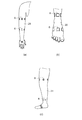
前記第1の実施形態では、麻痺した手3cの治療にリハビリ装置1が用いられた。手3c以外の治療にリハビリ装置1を用いても良い。図7(a)は、治療する腕の模式図である。図7(a)に示すように、腕29に複数のマーク6を設置して、腕29のリハビリ治療にリハビリ装置1を用いても良い。このとき、リハビリ装置1では腕が動く動画を腕29に重ねて形成し、ヘッドマウントディスプレイ2にて動画を表示する。これにより、腕29のリハビリを1人で行うことができる。
Note that the present embodiment is not limited to the above-described embodiment, and various changes and improvements can be added by those having ordinary knowledge in the art within the technical idea of the present invention. A modification will be described below.
(Modification 1)
In the first embodiment, the
図7(b)は、治療する足の模式図である。図7(b)に示すように、足30に複数のマーク6を設置して、足30のリハビリ治療にリハビリ装置1を用いても良い。このとき、リハビリ装置1では足が動く動画を足30に重ねて形成し、ヘッドマウントディスプレイ2にて動画を表示する。これにより、足30のリハビリを1人で行うことができる。
FIG. 7B is a schematic diagram of a foot to be treated. As shown in FIG. 7B, the
図7(c)は、治療する脚の模式図である。図7(c)に示すように、脚31に複数のマーク6を設置して、脚31のリハビリ治療にリハビリ装置1を用いても良い。このとき、リハビリ装置1では脚が動く動画を脚31に重ねて形成し、ヘッドマウントディスプレイ2にて動画を表示する。これにより、脚31のリハビリを1人で行うことができる。
FIG.7 (c) is a schematic diagram of the leg to be treated. As shown in FIG. 7C, the
(変形例2)
前記第1の実施形態では、画像形成部18は立体画像の動画を形成し、ヘッドマウントディスプレイ2は立体画像を表示した。画像形成部18は平面画像を形成し、ヘッドマウントディスプレイ2は平面画像を表示しても良い。平面画像は立体画像に比べてデータ数が少ないので、短時間で画像を形成することができる。そして、記憶部12の記憶容量を小さくすることができる。従って、リハビリ装置1を製造し易い装置にすることができる。
(Modification 2)
In the first embodiment, the
(変形例3)
前記第1の実施形態では、手3cにマーク6を設置した。マーク6の図案は枠6a、方向指示図6b及び識別図6cに限らない。他の図案でもよい。例えば、円や楕円、多角形により構成されてもよい。位置認識部17が認識し易い図案にしても良い。
(Modification 3)
In the first embodiment, the
(変形例4)
前記第1の実施形態では、ヘッドマウントディスプレイ2に1台のカメラ4が設置された。2台以上のカメラ4が設置されても良い。そして、三角測量の方法を用いてカメラ4とマーク6との距離を計測しても良い。他にも、フォーカスを合わせる機構を用いてカメラ4とマーク6との距離を計測しても良い。計測し易い方法を用いても良い。
(Modification 4)
In the first embodiment, one camera 4 is installed on the head mounted
(変形例5)
前記第1の実施形態では、手3cに複数のマーク6が設置された。手3cには連続する1つのマークが設置されても良い。そして、カメラ4から撮影される場所の図案で手3cの姿勢がわかるようにしても良い。
(Modification 5)
In the first embodiment, a plurality of
(変形例6)
前記第1の実施形態では、リハビリ装置1を用いて1人でリハビリ治療を行えるとした。介助者がリハビリ治療を行っても良い。このとき、介助者は複数の患者3を同時に介助することができるので、効率よくリハビリ治療を行うことができる。
(Modification 6)
In the first embodiment, it is assumed that one person can perform rehabilitation treatment using the
(変形例7)
前記第1の実施形態では、リハビリ装置1を用いて手3cのリハビリ治療を行った。リハビリ装置1を用いて指のリハビリ治療を行っても良い。指に小型のマーク6を設置することにより、第1の実施形態と同様に行うことができる。
(Modification 7)
In the first embodiment, the rehabilitation treatment of the
(変形例8)
前記第1の実施形態では、指を曲げて伸ばす動作の動画を形成した。他の動作の動画を形成しても良い。例えば、1本の指を伸ばして、他の指を曲げる動作にしても良い。他にも、グー、チョキ、パーの形態の動作にしても良い。各種の動画を用いることにより、患者3がリハビリ治療を継続し易くすることができる。
(Modification 8)
In the first embodiment, a moving image of bending and extending a finger is formed. You may form the animation of another operation | movement. For example, one finger may be extended and another finger may be bent. In addition, the operation may be in the form of goo, choki, or par. By using various moving images, the
(変形例9)
前記第1の実施形態では、鏡部2aは非透過型の鏡とした。鏡部2aは透過型でも良い。このとき、画像形成部18は鏡部2aを透過して見える手3cと動画の手3cが重なって見えるように動画を形成する。これにより、患者3は麻痺した手3cが動くように体感することができる。更に、鏡部2aにカバーをつけて透過型と非透過型とを切り替えるようにしても良い。手3cが動くように体感し易い方を選択することができる。
(Modification 9)
In the first embodiment, the
(変形例10)
前記第1の実施形態では、ヘッドマウントディスプレイ2が動画を表示した。これに限らず、患者3の眼3bと手3cとの間に動画を表示する装置を配置しても良い。動画を見やすい表示装置を選択できるようにしても良い。疲れ難いリハビリ治療を行うことができる。
(Modification 10)
In the first embodiment, the head mounted
(変形例11)
前記第1の実施形態では、撮影画像22と模擬画像23とを重ねて表示した。撮影画像22を表示せずに模擬画像23のみを表示しても良い。患者3が入出力端末8を操作して撮影画像22と模擬画像23との重なった画像の表示と模擬画像23の表示とを選択できるようにしても良い。患者3が手3cの動きを体感し易い方を選択することができる。
(Modification 11)
In the first embodiment, the captured
1…幻肢痛治療支援装置としてのリハビリ装置、2…表示部としてのヘッドマウントディスプレイ、3c…麻痺した身体部分としての手、4…撮影部及び撮像装置としてのカメラ、6…マーク、8…入力部としての入出力端末、17…認識部としての位置認識部、18…画像形成部。
DESCRIPTION OF
Claims (8)
前記麻痺した身体部分に設置されたマークを撮影し撮影画像を出力する撮影部と、
前記撮影画像を入力し前記マークの画像を用いて前記麻痺した身体部分の位置を認識する認識部と、
前記麻痺した身体部分が動く動画を出力する画像形成部と、
前記麻痺した身体部分に重ねて前記動画を表示する表示部と、を備えることを特徴とするリハビリ装置。 A rehabilitation device that restores the function of a paralyzed body part,
A photographing unit for photographing a mark placed on the paralyzed body part and outputting a photographed image;
A recognition unit that inputs the captured image and recognizes the position of the paralyzed body part using the image of the mark;
An image forming unit that outputs a moving image of the paralyzed body part; and
A rehabilitation device comprising: a display unit configured to display the moving image over the paralyzed body part.
前記認識部は前記マークの画像を用いて前記麻痺した身体部分の姿勢を認識し、
前記画像形成部は前記麻痺した身体部分の姿勢と同じ姿勢で動く動画を出力することを特徴とするリハビリ装置。 The rehabilitation device according to claim 1,
The recognition unit recognizes the posture of the paralyzed body part using the image of the mark,
The rehabilitation apparatus, wherein the image forming unit outputs a moving image in the same posture as the posture of the paralyzed body part.
前記認識部は前記マークの画像を用いて前記マークと前記撮影部との距離を認識し、
前記画像形成部は前記麻痺した身体部分が動く動画を前記距離に応じた大きさで出力することを特徴とするリハビリ装置。 The rehabilitation device according to claim 1 or 2,
The recognition unit recognizes a distance between the mark and the photographing unit using an image of the mark,
The rehabilitation apparatus, wherein the image forming unit outputs a moving image in which the paralyzed body part moves in a size corresponding to the distance.
前記認識部は前記マークの画像を用いて前記麻痺した身体部分が延在する方向を認識し、
前記画像形成部は前記麻痺した身体部分が向く方向と同じ方向を向いて動く動画を出力することを特徴とするリハビリ装置。 It is a rehabilitation device according to any one of claims 1 to 3,
The recognition unit recognizes the direction in which the paralyzed body part extends using the image of the mark,
The rehabilitation apparatus, wherein the image forming unit outputs a moving image that moves in the same direction as a direction in which the paralyzed body part faces.
前記撮影部が有する撮像装置の台数は1台であることを特徴とするリハビリ装置。 It is a rehabilitation apparatus as described in any one of Claims 1-4,
The rehabilitation apparatus according to claim 1, wherein the number of imaging devices included in the photographing unit is one.
前記マークは前記麻痺した身体部分に複数設置されることを特徴とするリハビリ装置。 It is a rehabilitation apparatus as described in any one of Claims 1-5,
A plurality of the marks are installed on the paralyzed body part.
前記画像形成部が出力する前記麻痺した身体部分が動く動画の早さを指示する入力部を備えることを特徴とするリハビリ装置。 It is a rehabilitation apparatus as described in any one of Claims 1-6,
A rehabilitation apparatus comprising: an input unit that instructs a speed of a moving image of the paralyzed body part output from the image forming unit.
前記欠損した身体部分に続く身体部分に設置されたマークを撮影する撮影部と、
前記マークを用いて前記欠損した身体部分の位置を認識する認識部と、
前記欠損した身体部分が動く動画を出力する画像形成部と、
前記欠損した身体部分の位置に前記動画を表示する表示部と、を備えることを特徴とする幻肢痛治療支援装置。 A phantom limb pain treatment support device that reduces pain in a missing body part,
An imaging unit for imaging a mark placed on a body part following the missing body part;
A recognition unit for recognizing the position of the missing body part using the mark;
An image forming unit that outputs a moving image of the deficient body part; and
And a display unit for displaying the moving image at the position of the missing body part.
Priority Applications (2)
| Application Number | Priority Date | Filing Date | Title |
|---|---|---|---|
| JP2013172039A JP2015039522A (en) | 2013-08-22 | 2013-08-22 | Rehabilitation device and assistive device for phantom limb pain treatment |
| US14/449,638 US20150054850A1 (en) | 2013-08-22 | 2014-08-01 | Rehabilitation device and assistive device for phantom limb pain treatment |
Applications Claiming Priority (1)
| Application Number | Priority Date | Filing Date | Title |
|---|---|---|---|
| JP2013172039A JP2015039522A (en) | 2013-08-22 | 2013-08-22 | Rehabilitation device and assistive device for phantom limb pain treatment |
Publications (2)
| Publication Number | Publication Date |
|---|---|
| JP2015039522A true JP2015039522A (en) | 2015-03-02 |
| JP2015039522A5 JP2015039522A5 (en) | 2016-09-15 |
Family
ID=52479956
Family Applications (1)
| Application Number | Title | Priority Date | Filing Date |
|---|---|---|---|
| JP2013172039A Withdrawn JP2015039522A (en) | 2013-08-22 | 2013-08-22 | Rehabilitation device and assistive device for phantom limb pain treatment |
Country Status (2)
| Country | Link |
|---|---|
| US (1) | US20150054850A1 (en) |
| JP (1) | JP2015039522A (en) |
Cited By (8)
| Publication number | Priority date | Publication date | Assignee | Title |
|---|---|---|---|---|
| WO2016190285A1 (en) * | 2015-05-26 | 2016-12-01 | 北海道公立大学法人札幌医科大学 | Rehabilitation system, program for rehabilitation, and rehabilitation method |
| JP2018110672A (en) * | 2017-01-11 | 2018-07-19 | 国立大学法人東京農工大学 | Display control device and display control program |
| JP2018149008A (en) * | 2017-03-10 | 2018-09-27 | セイコーエプソン株式会社 | Training device that can be used for rehabilitation and computer program for training device that can be used for rehabilitation |
| JP2018191964A (en) * | 2017-05-16 | 2018-12-06 | 株式会社Kids | Neuropathy-related pain treatment support system and pain treatment support method |
| RU2693692C1 (en) * | 2017-10-03 | 2019-07-03 | Магомед-Амин Исаевич Идилов | System of technical means for treating phantom pains |
| US10839706B2 (en) | 2016-09-30 | 2020-11-17 | Seiko Epson Corporation | Motion training device, program, and display method |
| KR20220063906A (en) * | 2020-11-11 | 2022-05-18 | 이준서 | Wearable apparatus, head mounted display apparatus and system for rehabilitation treatment using virtual transplant based on vr/ar for overcoming phantom pain |
| KR20220064593A (en) * | 2020-11-12 | 2022-05-19 | 이준서 | Apparatus for rehabilitation treatment using virtual transplant based on vr/ar for overcoming phantom pain |
Families Citing this family (7)
| Publication number | Priority date | Publication date | Assignee | Title |
|---|---|---|---|---|
| WO2015064144A1 (en) * | 2013-10-30 | 2015-05-07 | オリンパスイメージング株式会社 | Image capturing device, image capturing method, and program |
| CA2933053A1 (en) * | 2013-12-20 | 2015-06-25 | Integrum Ab | System for neuromuscular rehabilitation |
| US9867961B2 (en) | 2014-03-13 | 2018-01-16 | Gary Stephen Shuster | Treatment of phantom limb syndrome and other sequelae of physical injury |
| WO2017021320A1 (en) * | 2015-07-31 | 2017-02-09 | Universitat De Barcelona | Motor training |
| AT520385B1 (en) * | 2017-06-07 | 2020-11-15 | Device with a detection unit for the position and posture of a first limb of a user | |
| CA3114040A1 (en) | 2018-09-26 | 2020-04-02 | Guardian Glass, LLC | Augmented reality system and method for substrates, coated articles, insulating glass units, and/or the like |
| TWI795684B (en) * | 2020-10-22 | 2023-03-11 | 仁寶電腦工業股份有限公司 | Sensing system and pairing method thereof |
Citations (2)
| Publication number | Priority date | Publication date | Assignee | Title |
|---|---|---|---|---|
| JP2004298430A (en) * | 2003-03-31 | 2004-10-28 | Toshiba Corp | Pain therapeutic support apparatus and method for displaying phantom limb image in animating manner in virtual space |
| JP2007020835A (en) * | 2005-07-15 | 2007-02-01 | National Institute Of Advanced Industrial & Technology | Rehabilitation apparatus |
Family Cites Families (9)
| Publication number | Priority date | Publication date | Assignee | Title |
|---|---|---|---|---|
| US20060293617A1 (en) * | 2004-02-05 | 2006-12-28 | Reability Inc. | Methods and apparatuses for rehabilitation and training |
| US8224024B2 (en) * | 2005-10-04 | 2012-07-17 | InterSense, LLC | Tracking objects with markers |
| US8953909B2 (en) * | 2006-01-21 | 2015-02-10 | Elizabeth T. Guckenberger | System, method, and computer software code for mimic training |
| US20080170750A1 (en) * | 2006-11-01 | 2008-07-17 | Demian Gordon | Segment tracking in motion picture |
| JP5547968B2 (en) * | 2007-02-14 | 2014-07-16 | コーニンクレッカ フィリップス エヌ ヴェ | Feedback device for instructing and supervising physical movement and method of operating |
| WO2008114166A2 (en) * | 2007-03-16 | 2008-09-25 | Philips Intellectual Property & Standards Gmbh | System for rehabilitation and/or physical therapy for the treatment of neuromotor disorders |
| EP2153370B1 (en) * | 2007-05-03 | 2017-02-15 | Motek B.V. | Method and system for real time interactive dynamic alignment of prosthetics |
| US20100315524A1 (en) * | 2007-09-04 | 2010-12-16 | Sony Corporation | Integrated motion capture |
| US8179604B1 (en) * | 2011-07-13 | 2012-05-15 | Google Inc. | Wearable marker for passive interaction |
-
2013
- 2013-08-22 JP JP2013172039A patent/JP2015039522A/en not_active Withdrawn
-
2014
- 2014-08-01 US US14/449,638 patent/US20150054850A1/en not_active Abandoned
Patent Citations (2)
| Publication number | Priority date | Publication date | Assignee | Title |
|---|---|---|---|---|
| JP2004298430A (en) * | 2003-03-31 | 2004-10-28 | Toshiba Corp | Pain therapeutic support apparatus and method for displaying phantom limb image in animating manner in virtual space |
| JP2007020835A (en) * | 2005-07-15 | 2007-02-01 | National Institute Of Advanced Industrial & Technology | Rehabilitation apparatus |
Cited By (13)
| Publication number | Priority date | Publication date | Assignee | Title |
|---|---|---|---|---|
| JPWO2016190285A1 (en) * | 2015-05-26 | 2018-05-10 | 北海道公立大学法人 札幌医科大学 | Rehabilitation system, rehabilitation program, and rehabilitation method |
| WO2016190285A1 (en) * | 2015-05-26 | 2016-12-01 | 北海道公立大学法人札幌医科大学 | Rehabilitation system, program for rehabilitation, and rehabilitation method |
| US10839706B2 (en) | 2016-09-30 | 2020-11-17 | Seiko Epson Corporation | Motion training device, program, and display method |
| JP2018110672A (en) * | 2017-01-11 | 2018-07-19 | 国立大学法人東京農工大学 | Display control device and display control program |
| JP2018149008A (en) * | 2017-03-10 | 2018-09-27 | セイコーエプソン株式会社 | Training device that can be used for rehabilitation and computer program for training device that can be used for rehabilitation |
| JP2018191964A (en) * | 2017-05-16 | 2018-12-06 | 株式会社Kids | Neuropathy-related pain treatment support system and pain treatment support method |
| RU2693692C1 (en) * | 2017-10-03 | 2019-07-03 | Магомед-Амин Исаевич Идилов | System of technical means for treating phantom pains |
| KR20220063906A (en) * | 2020-11-11 | 2022-05-18 | 이준서 | Wearable apparatus, head mounted display apparatus and system for rehabilitation treatment using virtual transplant based on vr/ar for overcoming phantom pain |
| KR102446921B1 (en) * | 2020-11-11 | 2022-09-22 | 이준서 | Wearable apparatus, head mounted display apparatus and system for rehabilitation treatment using virtual transplant based on vr/ar for overcoming phantom pain |
| KR20220131886A (en) * | 2020-11-11 | 2022-09-29 | 이준서 | Apparatus for rehabilitation treatment using virtual transplant based on vr/ar for overcoming phantom pain |
| KR102499113B1 (en) * | 2020-11-11 | 2023-02-10 | 이준서 | Apparatus for rehabilitation using virtual transplant based on vr/ar for overcoming phantom pain |
| KR20220064593A (en) * | 2020-11-12 | 2022-05-19 | 이준서 | Apparatus for rehabilitation treatment using virtual transplant based on vr/ar for overcoming phantom pain |
| KR102446922B1 (en) * | 2020-11-12 | 2022-09-22 | 이준서 | Apparatus for rehabilitation treatment using virtual transplant based on vr/ar for overcoming phantom pain |
Also Published As
| Publication number | Publication date |
|---|---|
| US20150054850A1 (en) | 2015-02-26 |
Similar Documents
| Publication | Publication Date | Title |
|---|---|---|
| JP2015039522A (en) | Rehabilitation device and assistive device for phantom limb pain treatment | |
| JP6393367B2 (en) | Tracking display system, tracking display program, tracking display method, wearable device using them, tracking display program for wearable device, and operation method of wearable device | |
| TWI476633B (en) | Tactile communication system | |
| JP6565212B2 (en) | Display device, display method, and program | |
| WO2013149586A1 (en) | Wrist-mounting gesture control system and method | |
| WO2014112631A1 (en) | Movement information processing device and program | |
| CN103744518B (en) | Stereo interaction method and display device thereof and system | |
| JP6052399B2 (en) | Image processing program, image processing method, and information terminal | |
| WO2016063801A1 (en) | Head mounted display, mobile information terminal, image processing device, display control program, and display control method | |
| JP2015109937A (en) | Movement information processing device | |
| JP6452440B2 (en) | Image display system, image display apparatus, image display method, and program | |
| US10839706B2 (en) | Motion training device, program, and display method | |
| Huang et al. | Smartglove for upper extremities rehabilitative gaming assessment | |
| JP2016206617A (en) | Display system | |
| WO2018020661A1 (en) | Display device, display control device and display control method | |
| EP3346368B1 (en) | Device, method and system for control of a target apparatus | |
| WO2017134732A1 (en) | Input device, input assistance method, and input assistance program | |
| US20230359422A1 (en) | Techniques for using in-air hand gestures detected via a wrist-wearable device to operate a camera of another device, and wearable devices and systems for performing those techniques | |
| JP2009259117A (en) | Mirror system | |
| WO2019159332A1 (en) | Information processing device, information processing system, controller device, information processing method, and program | |
| US20230419719A1 (en) | Camera device and camera system | |
| JP7427937B2 (en) | Image processing device, image processing method, and program | |
| WO2019065303A1 (en) | Service provision system, service provision method, and management device for service provision system | |
| JP2024056349A (en) | Exercise support device and program | |
| JP6149211B2 (en) | Mobile terminal device, program, and camera shake correction method |
Legal Events
| Date | Code | Title | Description |
|---|---|---|---|
| RD04 | Notification of resignation of power of attorney |
Free format text: JAPANESE INTERMEDIATE CODE: A7424 Effective date: 20150114 |
|
| RD04 | Notification of resignation of power of attorney |
Free format text: JAPANESE INTERMEDIATE CODE: A7424 Effective date: 20160617 |
|
| RD03 | Notification of appointment of power of attorney |
Free format text: JAPANESE INTERMEDIATE CODE: A7423 Effective date: 20160624 |
|
| A521 | Request for written amendment filed |
Free format text: JAPANESE INTERMEDIATE CODE: A523 Effective date: 20160729 |
|
| A621 | Written request for application examination |
Free format text: JAPANESE INTERMEDIATE CODE: A621 Effective date: 20160729 |
|
| A977 | Report on retrieval |
Free format text: JAPANESE INTERMEDIATE CODE: A971007 Effective date: 20170519 |
|
| A131 | Notification of reasons for refusal |
Free format text: JAPANESE INTERMEDIATE CODE: A131 Effective date: 20170530 |
|
| A761 | Written withdrawal of application |
Free format text: JAPANESE INTERMEDIATE CODE: A761 Effective date: 20170721 |