JP2015028595A - Projector, control method of projector, and display device - Google Patents
Projector, control method of projector, and display device Download PDFInfo
- Publication number
- JP2015028595A JP2015028595A JP2014057672A JP2014057672A JP2015028595A JP 2015028595 A JP2015028595 A JP 2015028595A JP 2014057672 A JP2014057672 A JP 2014057672A JP 2014057672 A JP2014057672 A JP 2014057672A JP 2015028595 A JP2015028595 A JP 2015028595A
- Authority
- JP
- Japan
- Prior art keywords
- color mode
- image
- projector
- illuminance
- color
- Prior art date
- Legal status (The legal status is an assumption and is not a legal conclusion. Google has not performed a legal analysis and makes no representation as to the accuracy of the status listed.)
- Withdrawn
Links
Images


Classifications
-
- H—ELECTRICITY
- H04—ELECTRIC COMMUNICATION TECHNIQUE
- H04N—PICTORIAL COMMUNICATION, e.g. TELEVISION
- H04N17/00—Diagnosis, testing or measuring for television systems or their details
- H04N17/004—Diagnosis, testing or measuring for television systems or their details for digital television systems
-
- G—PHYSICS
- G09—EDUCATION; CRYPTOGRAPHY; DISPLAY; ADVERTISING; SEALS
- G09G—ARRANGEMENTS OR CIRCUITS FOR CONTROL OF INDICATING DEVICES USING STATIC MEANS TO PRESENT VARIABLE INFORMATION
- G09G3/00—Control arrangements or circuits, of interest only in connection with visual indicators other than cathode-ray tubes
- G09G3/001—Control arrangements or circuits, of interest only in connection with visual indicators other than cathode-ray tubes using specific devices not provided for in groups G09G3/02 - G09G3/36, e.g. using an intermediate record carrier such as a film slide; Projection systems; Display of non-alphanumerical information, solely or in combination with alphanumerical information, e.g. digital display on projected diapositive as background
- G09G3/002—Control arrangements or circuits, of interest only in connection with visual indicators other than cathode-ray tubes using specific devices not provided for in groups G09G3/02 - G09G3/36, e.g. using an intermediate record carrier such as a film slide; Projection systems; Display of non-alphanumerical information, solely or in combination with alphanumerical information, e.g. digital display on projected diapositive as background to project the image of a two-dimensional display, such as an array of light emitting or modulating elements or a CRT
-
- G—PHYSICS
- G09—EDUCATION; CRYPTOGRAPHY; DISPLAY; ADVERTISING; SEALS
- G09G—ARRANGEMENTS OR CIRCUITS FOR CONTROL OF INDICATING DEVICES USING STATIC MEANS TO PRESENT VARIABLE INFORMATION
- G09G2320/00—Control of display operating conditions
- G09G2320/06—Adjustment of display parameters
- G09G2320/0666—Adjustment of display parameters for control of colour parameters, e.g. colour temperature
-
- G—PHYSICS
- G09—EDUCATION; CRYPTOGRAPHY; DISPLAY; ADVERTISING; SEALS
- G09G—ARRANGEMENTS OR CIRCUITS FOR CONTROL OF INDICATING DEVICES USING STATIC MEANS TO PRESENT VARIABLE INFORMATION
- G09G2330/00—Aspects of power supply; Aspects of display protection and defect management
- G09G2330/02—Details of power systems and of start or stop of display operation
- G09G2330/026—Arrangements or methods related to booting a display
-
- G—PHYSICS
- G09—EDUCATION; CRYPTOGRAPHY; DISPLAY; ADVERTISING; SEALS
- G09G—ARRANGEMENTS OR CIRCUITS FOR CONTROL OF INDICATING DEVICES USING STATIC MEANS TO PRESENT VARIABLE INFORMATION
- G09G2354/00—Aspects of interface with display user
-
- G—PHYSICS
- G09—EDUCATION; CRYPTOGRAPHY; DISPLAY; ADVERTISING; SEALS
- G09G—ARRANGEMENTS OR CIRCUITS FOR CONTROL OF INDICATING DEVICES USING STATIC MEANS TO PRESENT VARIABLE INFORMATION
- G09G2360/00—Aspects of the architecture of display systems
- G09G2360/14—Detecting light within display terminals, e.g. using a single or a plurality of photosensors
- G09G2360/144—Detecting light within display terminals, e.g. using a single or a plurality of photosensors the light being ambient light
Abstract
Description
本発明は、プロジェクター、プロジェクターの制御方法および表示装置に関する。 The present invention relates to a projector, a projector control method, and a display device.
従来、画像をスクリーン等の投写面に投写するプロジェクターにおいて、画像の種類、また周囲の明るさに応じて複数の画質調整値を設定するカラーモード機能が搭載されている。例えば暗い部屋で映画を鑑賞する場合のシアターモード、明るい部屋で投写画像をより明るく投写する場合のダイナミックモードなどがある。明るい部屋でシアターモードに設定すると画像が暗くて見にくくなることや、逆に暗い部屋でダイナミックモードに設定すると画像が明るすぎて眩しすぎることがあった。このため、特許文献1のように、周囲の明るさに対応したカラーモードを設定するプロジェクターが開示されている。このようなプロジェクターによればあらかじめ設定された照度に対応して自動的にカラーモードが設定される。 2. Description of the Related Art Conventionally, a projector that projects an image on a projection surface such as a screen is equipped with a color mode function that sets a plurality of image quality adjustment values according to the type of image and ambient brightness. For example, there are a theater mode for watching a movie in a dark room and a dynamic mode for projecting a projected image brighter in a bright room. When the theater mode is set in a bright room, the image is dark and difficult to see. Conversely, when the dynamic mode is set in a dark room, the image is too bright and too dazzling. For this reason, a projector that sets a color mode corresponding to ambient brightness is disclosed, as in Japanese Patent Application Laid-Open No. H10-228707. According to such a projector, the color mode is automatically set according to the preset illuminance.
しかし、特許文献1のようなプロジェクターでは、投写する画像の種類、部屋の明るさなどの視聴環境により、設定されたカラーモードが必ずしもユーザーの所望する設定とならない可能性があった。また、明るさの変化により、意図しないときにカラーモードが切り替わってしまうため、ユーザーが戸惑う虞があった。 However, in a projector such as Patent Document 1, the set color mode may not necessarily be a setting desired by the user depending on the viewing environment such as the type of image to be projected and the brightness of the room. In addition, since the color mode is switched when it is not intended due to a change in brightness, the user may be confused.
本発明は、上述した課題の少なくとも一部を解決するためになされたものであり、以下の形態または適用例として実現することが可能である。 SUMMARY An advantage of some aspects of the invention is to solve at least a part of the problems described above, and the invention can be implemented as the following forms or application examples.
[適用例1]本適用例に係るプロジェクターは、光源から射出された光を、入力される画像信号に基づく画像情報に応じて変調し、投写面に画像を投写する画像投写手段を有するプロジェクターであって、当該プロジェクターの外部の照度を測定する照度測定手段と、前記画像の画質調整を設定するための複数のカラーモードを備え、前記画像をいずれかの前記カラーモードに設定するカラーモード設定手段と、測定した前記照度の範囲に対応する前記カラーモードを定義するカラーモードテーブルを記憶する記憶手段と、当該プロジェクターが電源オンされたときに、前記カラーモードテーブルに基づき、前記照度の範囲に対し対応しない前記カラーモードが設定されていた場合に報知する制御手段と、を備えたことを特徴とする。 Application Example 1 A projector according to this application example is a projector having an image projection unit that modulates light emitted from a light source according to image information based on an input image signal and projects an image on a projection surface. An illuminance measuring unit that measures illuminance outside the projector and a plurality of color modes for setting image quality adjustment of the image, and a color mode setting unit that sets the image to any one of the color modes. Storage means for storing a color mode table that defines the color mode corresponding to the measured illuminance range, and the illuminance range based on the color mode table when the projector is powered on. Control means for informing when the color mode that does not correspond is set.
本適用例によれば、プロジェクターが電源オンされたときに、外部の照度に対応しないカラーモードが設定されていた場合に報知するので、照度に対応するカラーモードへの変更をユーザーに促すことが可能となる。 According to this application example, when the projector is turned on, a notification is made when a color mode that does not correspond to external illuminance is set, so the user is prompted to change to a color mode that corresponds to illuminance. It becomes possible.
[適用例2]上記適用例に記載のプロジェクターにおいて、前記制御手段は、前記照度測定手段により、前記照度が変化したことを検出した場合、前記カラーモードテーブルに基づき、前記照度の範囲に対し対応しない前記カラーモードが設定されていた場合に報知することが好ましい。 Application Example 2 In the projector according to the application example, when the illuminance measurement unit detects that the illuminance has changed, the control unit responds to the illuminance range based on the color mode table. It is preferable to notify when the color mode is not set.
本適用例によれば、プロジェクターが動作中に照度の変化を検出したとき、カラーモードが照度に対応しない場合に報知するので、プロジェクターの使用環境が変わった場合、現在のカラーモードが照度に適さないことを報知し、照度に対応するカラーモードへの変更をユーザーに促すことが可能となる。 According to this application example, when a change in illuminance is detected during operation of the projector, a notification is given when the color mode does not correspond to the illuminance. Therefore, if the usage environment of the projector changes, the current color mode is suitable for the illuminance. It is possible to notify the user that there is no color and to prompt the user to change to the color mode corresponding to the illuminance.
[適用例3]上記適用例に記載のプロジェクターにおいて、前記制御手段は、前記カラーモード設定手段により、前記カラーモードが変更されたとき、前記カラーモードテーブルに基づき、前記照度の範囲に対し対応しない前記カラーモードに変更された場合に報知することが好ましい。 Application Example 3 In the projector according to the application example, the control unit does not correspond to the illuminance range based on the color mode table when the color mode is changed by the color mode setting unit. It is preferable to notify when the color mode is changed.
本適用例によれば、プロジェクターのカラーモードを変更したとき、新たなカラーモードが現在の照度に対応しない場合に報知するので、照度に対応するカラーモードへの変更をユーザーに促すことが可能となる。 According to this application example, when the color mode of the projector is changed, notification is made when the new color mode does not correspond to the current illuminance, so it is possible to prompt the user to change to the color mode corresponding to the illuminance. Become.
[適用例4]上記適用例に記載のプロジェクターにおいて、前記制御手段は、前記カラーモードテーブルに基づき、前記照度に対応する前記カラーモードの一覧を前記画像投写手段により投写することが好ましい。 Application Example 4 In the projector according to the application example, it is preferable that the control unit projects the color mode list corresponding to the illuminance by the image projection unit based on the color mode table.
本適用例によれば、現在の照度に対応するカラーモードの一覧が表示されるので、ユーザーが、照度に対応するカラーモードを選択することが可能となる。 According to this application example, since a list of color modes corresponding to the current illuminance is displayed, the user can select a color mode corresponding to the illuminance.
[適用例5]本適用例に係るプロジェクターの制御方法は、光源から射出された光を、入力される画像信号に基づく画像情報に応じて変調し、投写面に画像を投写する画像投写手段を有するプロジェクターの制御方法であって、当該プロジェクターの外部の照度を測定する照度測定ステップと、前記画像の画質調整を設定するための複数のカラーモードを備え、前記画像をいずれかの前記カラーモードに設定するカラーモード設定ステップと、測定した前記照度の範囲に対応する前記カラーモードが設定されているか否かを判断する判断ステップと、当該プロジェクターが電源オンされたときに、前記判断ステップにより、測定した前記照度の範囲に対応する前記カラーモードが設定されていないと判断された場合に報知する報知ステップと、を有することを特徴とする。 Application Example 5 A projector control method according to this application example includes an image projection unit that modulates light emitted from a light source according to image information based on an input image signal and projects an image on a projection surface. A projector control method comprising: an illuminance measurement step for measuring illuminance outside the projector; and a plurality of color modes for setting image quality adjustment of the image, wherein the image is set to any one of the color modes. A color mode setting step to be set, a determination step for determining whether or not the color mode corresponding to the measured illuminance range is set, and a measurement by the determination step when the projector is turned on. A notification step for notifying when it is determined that the color mode corresponding to the illuminance range is not set; Characterized in that it has a.
本適用例によれば、プロジェクターが電源オンされたときに、外部の照度に対応しないカラーモードが設定されていた場合に報知するので、照度に対応するカラーモードへの変更をユーザーに促すことが可能となる。 According to this application example, when the projector is turned on, a notification is made when a color mode that does not correspond to external illuminance is set, so the user is prompted to change to a color mode that corresponds to illuminance. It becomes possible.
[適用例6]本適用例に係る表示装置は、入力される画像信号に基づく画像情報に応じた画像を表示する表示装置であって、当該表示装置の外部の照度を測定する照度測定手段と、前記画像の画質調整を設定するための複数のカラーモードを備え、前記画像をいずれかの前記カラーモードに設定するカラーモード設定手段と、測定した前記照度の範囲に対応する前記カラーモードを定義するカラーモードテーブルを記憶する記憶手段と、当該表示装置が電源オンされたときに、前記カラーモードテーブルに基づき、前記照度の範囲に対応しない前記カラーモードが設定されていた場合に報知する制御手段と、を備えたことを特徴とする。 Application Example 6 A display device according to this application example is a display device that displays an image according to image information based on an input image signal, and an illuminance measuring unit that measures illuminance outside the display device. A plurality of color modes for setting image quality adjustment of the image, color mode setting means for setting the image to any one of the color modes, and defining the color mode corresponding to the measured illuminance range Storage means for storing the color mode table, and control means for notifying when the color mode not corresponding to the illuminance range is set based on the color mode table when the display device is powered on. And.
本適用例によれば、表示装置が電源オンされたときに、外部の照度に対応しないカラーモードが設定されていた場合に報知するので、照度に対応するカラーモードへの変更をユーザーに促すことが可能となる。 According to this application example, when a color mode that does not correspond to external illuminance is set when the display device is turned on, the user is prompted to change to a color mode that corresponds to illuminance. Is possible.
以下、図面を参照して本発明の一実施形態について説明するが、以下の実施形態は特許請求の範囲にかかる発明を限定するものではなく、また、実施形態における特徴の組み合わせの全てが発明の解決手段に必須であるとは限らない。 Hereinafter, an embodiment of the present invention will be described with reference to the drawings. However, the following embodiment does not limit the invention according to the scope of claims, and all combinations of features in the embodiment are based on the invention. It is not always essential to the solution.
(実施形態)
図1は、本実施形態の表示装置としてのプロジェクター1の回路構成を示すブロック図である。
図1に示すように、プロジェクター1は、画像入力端子6、画像投写手段10、OSD処理手段16、画像信号処理手段17、画像信号入力手段18、照度測定手段19、制御手段20、記憶手段21、光源制御手段22、入力操作手段23、電源端子30、電源部31等で構成されており、これらは図示しない筐体の内部または外面に配置されている。
(Embodiment)
FIG. 1 is a block diagram showing a circuit configuration of a projector 1 as a display device of the present embodiment.
As shown in FIG. 1, the projector 1 includes an
画像投写手段10は、光源11、光変調装置としての3つの液晶ライトバルブ12R,12G,12B、投写光学系としての投写レンズ13、液晶駆動手段14等を含んでいる。画像投写手段10は、光源11から射出された光を、液晶ライトバルブ12R,12G,12Bで変調し、変調された画像を投写レンズ13から投写することによってスクリーンSC等の投写面に投写画像を表示する。
The image projection means 10 includes a
光源11は、超高圧水銀ランプやメタルハライドランプ等からなる放電型の光源ランプ11aと、光源ランプ11aが放射した光を液晶ライトバルブ12R,12G,12B側に反射するリフレクター11bとを含んで構成されている。
光源11から射出された光は、図示しないインテグレーター光学系によって輝度分布が略均一な光に変換され、図示しない色分離光学系によって光の3原色である赤色(R)、緑色(G)、青色(B)の各色光成分に分離された後、それぞれ対応する液晶ライトバルブ12R,12G,12Bに入射する。
The
Light emitted from the
液晶ライトバルブ12R,12G,12Bは、一対の透明基板間に液晶が封入された液晶パネル等によって構成される。液晶ライトバルブ12R,12G,12Bには、マトリックス状に配列された複数の画素(図示せず)が形成されており、液晶に対して画素毎に駆動電圧を印加可能になっている。
The liquid
液晶駆動手段14が、入力される画像データに応じた駆動電圧を各画素に印加すると、各画素は、画像情報に応じた光透過率に設定される。このため、光源11から射出された光は、この液晶ライトバルブ12R,12G,12Bを透過することによって変調され、画像情報に応じた画像光が色光毎に形成される。
形成された各色の画像光は、図示しない色合成光学系によって画素毎に合成されてカラーの画像光となった後、投写レンズ13によってスクリーンSC等に拡大投写され投写画像となる。
When the liquid
The formed image light of each color is synthesized for each pixel by a color synthesis optical system (not shown) to become color image light, and then enlarged and projected onto the screen SC or the like by the
本実施形態では、光源として光源ランプ11aを用いて投写するプロジェクター1を例示したが、本発明は、光源としてLED(Light emitting diode)光源やレーザー光源などを用いて投写するプロジェクターにも適用することができる。
In the present embodiment, the projector 1 that projects using the
なお、本実施形態では、画像投写手段10は、3つの液晶ライトバルブ12R,12G,12Bを用いた透過型液晶方式の投写光学系を例示したが、反射型液晶表示方式やマイクロミラーデバイス方式(ライトスイッチ表示方式)など、他の表示方式の光変調装置を採用しても良い。
In the present embodiment, the image projection means 10 is exemplified by a transmissive liquid crystal type projection optical system using three liquid
制御手段20は、図示しないCPU(Central Processing Unit)や、各種データ等の一時記憶に用いられるRAM(Random Access Memory)等を備え、記憶手段21に記憶されている制御プログラム(図示せず)に従って動作することによりプロジェクター1の動作を統括制御する。つまり、制御手段20は、記憶手段21とともにコンピューターとして機能する。制御手段20はカラーモード設定手段201を備える。カラーモード設定手段201は、画像投写手段10に投写させる画像の画質調整を設定するための複数のカラーモードの中からいずれかを選択し、設定する。カラーモードとは、画像の種別や視聴環境等に応じて画質を調整するための項目であり、例えば、明るい環境で、暗部の階調表現を重視する視聴に適する「ダイナミック」や、薄明かりの中での視聴に適する「リビング」、暗い環境下での映画鑑賞に適する「シアター」、明るい環境で写真などの静止画像を投写するのに適する「フォト」、明るい環境でカラーの資料を使ってプレゼンテーションするのに適する「プレゼンテーション」、明るい環境でゲームをするのに適する「ゲーム」等のカラーモードがある。
The control means 20 includes a CPU (Central Processing Unit) (not shown), a RAM (Random Access Memory) used for temporary storage of various data, and the like, according to a control program (not shown) stored in the storage means 21. By operating, the overall operation of the projector 1 is controlled. That is, the
記憶手段21は、フラッシュメモリーやFeRAM(Ferroelectric RAM:強誘電体メモリー)等の書き換え可能な不揮発性のメモリーにより構成されている。記憶手段21には、プロジェクター1の動作を制御するための制御プログラムや、プロジェクター1の動作条件等を規定する各種設定データ等が記憶されている。本実施形態ではプロジェクター1の周囲の照度の範囲に対応するカラーモードが定義されたカラーモードテーブル211が保存される。具体的には測定した照度の範囲毎にそれぞれのカラーモードが対応しているか否かの定義内容が保存されている。
The storage means 21 is composed of a rewritable nonvolatile memory such as a flash memory or FeRAM (Ferroelectric RAM). The
図5はカラーモードテーブル211の保存内容の例を示す図である。図5に示すように、測定された照度の範囲に対し、各カラーモードが対応するか否かをYes、またはNoで定義されている。例えば、測定された照度が301〜500Luxのときは、ダイナミック、プレゼンテーション、ゲームの各カラーモードが対応し、測定された照度が0〜5Luxのときは、シアターモードのみが対応していることを示す。 FIG. 5 is a diagram showing an example of the contents stored in the color mode table 211. As shown in FIG. 5, whether each color mode corresponds to the measured illuminance range is defined as Yes or No. For example, when the measured illuminance is 301 to 500 Lux, each color mode of dynamic, presentation, and game corresponds, and when the measured illuminance is 0 to 5 Lux, it indicates that only the theater mode is supported. .
図1に戻って、入力操作手段23は、ユーザーがプロジェクター1に対して各種指示を行うための複数の操作キーを備えている。入力操作手段23が備える操作キーとしては、電源のオン・オフを交互に切り替えるための電源キーや、画像信号入力手段18に入力される複数の画像入力端子6を切り替えるための入力切替キー、各種設定を行うための設定メニューを重畳表示させるメニューキー、メニューからユーザーが設定項目を選択するカーソルキー、各種設定を決定するための決定キー、設定中の画面を戻すためのエスケープキー、カラーモードを選択するためのカラーモードキー等がある。
Returning to FIG. 1, the input operation means 23 includes a plurality of operation keys for the user to give various instructions to the projector 1. The operation keys provided in the input operation means 23 include a power key for alternately switching on / off the power supply, an input switching key for switching a plurality of
ユーザーが入力操作手段23の各種操作キーを操作すると、入力操作手段23は、ユーザーの操作内容に応じた操作信号を制御手段20に出力する。なお、入力操作手段23は、リモートコントローラー(リモコン)信号受信手段(図示せず)と遠隔操作が可能なリモートコントローラー(図示せず)を有した構成としてもよい。この場合、リモートコントローラーは、ユーザーの操作内容に応じた赤外線等の操作信号を発し、リモコン信号受信手段がこれを受信して制御情報として制御手段20に伝達する。
When the user operates various operation keys of the
照度測定手段19は、光センサー(図示せず)等を有して構成され、制御手段20の指示に基づいて、プロジェクター1の外部の照度を測定する。そして、測定した照度を制御手段20に通知する。 The illuminance measuring means 19 includes an optical sensor (not shown) and the like, and measures the illuminance outside the projector 1 based on an instruction from the control means 20. The measured illuminance is notified to the control means 20.
光源制御手段22は、制御手段20の指示に基づいて、光源11に対する電力の供給と停止とを制御し、光源11の点灯、および消灯を切り替える。
The light
画像信号入力手段18は、複数の画像入力端子6より、ビデオ再生装置やパーソナルコンピューター等、外部の画像出力装置から、図示しないケーブル、又は通信機器などを介して画像情報が入力される。入力された画像情報は、制御手段20の指示に基づき、画像信号処理手段17に出力される。なお、画像信号入力手段18は、無線通信や光通信などの受信部を備え、外部機器から無線によって画像信号を入力する構成にしてもよい。
The image signal input means 18 receives image information from a plurality of
画像信号処理手段17は、制御手段20の指示に基づき、画像信号入力手段18から入力される画像情報を、液晶ライトバルブ12R,12G,12Bの各画素の階調を表す画像データに変換する。ここで、変換された画像情報は、赤(R)、緑(G)、青(B)の色光別になっており、各液晶ライトバルブ12R,12G,12Bのすべての画素に対応する複数の画素値によって構成されている。画素値とは、対応する画素の光透過率を定めるものであり、この画素値によって、各画素を透過し射出する光の強弱(階調)が規定される。
The image
OSD処理手段16は、制御手段20の指示に基づいて、投写画像上に、メニュー画像やメッセージ画像等のOSD(オンスクリーンディスプレイ)画像を重畳して表示するための処理を行う。OSD処理手段16は、図示しないOSDメモリーを備えており、OSD画像を形成するための図形やフォント等を表すOSD画像データを記憶している。
The
制御手段20が、OSD画像の重畳表示を指示すると、OSD処理手段16は、必要なOSD画像データをOSDメモリーから読み出し、投写画像上の所定の位置にOSD画像が重畳されるように、画像信号処理手段17から入力される画像データにこのOSD画像データを合成する。OSD画像情報が合成された画像データは、液晶駆動手段14に出力される。
なお、制御手段20からOSD画像を重畳する旨の指示がない場合には、OSD処理手段16は、画像信号処理手段17から入力される画像データを、そのまま液晶駆動手段14に出力する。
When the control means 20 instructs to superimpose the OSD image, the OSD processing means 16 reads the necessary OSD image data from the OSD memory, and outputs an image signal so that the OSD image is superimposed at a predetermined position on the projected image. The OSD image data is synthesized with the image data input from the processing means 17. The image data combined with the OSD image information is output to the liquid crystal driving means 14.
When there is no instruction to superimpose the OSD image from the
液晶駆動手段14が、OSD処理手段16より入力される画像データに従って液晶ライトバルブ12R,12G,12Bを駆動すると、画像データに応じた画像が投写レンズ13より投写され、スクリーンSCの投写面に投写画像が表示される。
When the liquid
電源部31には、電源端子30を介してAC100V等の電力が外部から供給される。電源部31は、入力した電力(交流電力)を所定の直流電力に変換して、プロジェクター1の各部に電力を供給する。また、電源部31は、制御手段20の指示に基づいて、画像の投写に必要な電力(動作電力)を各部に供給する状態(電源オン状態)と、動作電力の供給を停止して、電源をオンにするための操作を待機する状態(スタンバイ状態)とを切り替えることができる。
The
次に、本実施形態のプロジェクター1の動作を図2、図3を用いて説明する。
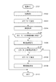
図2はプロジェクター1が電源オンされたときの動作を示すフローチャート、図3はプロジェクター1が動作中に外部の照度の変化を検出したとき、およびカラーモードの変更操作を受け付けたときの動作を示すフローチャートである。
Next, the operation of the projector 1 according to the present embodiment will be described with reference to FIGS.
FIG. 2 is a flowchart showing an operation when the projector 1 is powered on, and FIG. 3 shows an operation when a change in external illuminance is detected while the projector 1 is operating and when a color mode changing operation is accepted. It is a flowchart.
〔電源オン時の動作〕
図2に示すように、プロジェクター1が入力操作手段23の電源キーなどにより電源オンすると(ステップS101)、制御手段20は、光源制御手段22に指示して光源11を点灯させ(ステップS102)、ステップS103に遷移する。
[Operation when the power is turned on]
As shown in FIG. 2, when the projector 1 is turned on by the power key of the input operation unit 23 (step S101), the
ステップS103において、カラーモード設定手段201は現在選択されているカラーモードに基づく画質調整値を画像投写手段10に設定し、ステップS104に遷移する。ステップS103がカラーモード設定ステップに相当する。
In step S103, the color
ステップS104において、制御手段20は、照度測定手段19によりプロジェクター1の外部の照度を測定してその測定結果を取得し、ステップS105に遷移する。ステップS104が照度測定ステップに相当する。
In step S104, the
ステップS105において、制御手段20は、カラーモードテーブル211に基づき、現在設定されているカラーモードが、ステップS104において取得した照度に対応するか否かを調べる。現在設定されているカラーモードが照度に対応する場合(ステップS105:Y)には、ステップS110に遷移する。カラーモードが照度に対応しない場合(ステップS105:N)にはステップS106に遷移する。ステップS105が判断ステップに相当する。
In step S105, the
図4は、照度の範囲に対応しないカラーモードが設定されている場合の画像の例を示す図である。
ステップS106において、制御手段20は、照度の範囲に対応しないカラーモードが設定されている場合には、図4に示すように、カラーモードが照度に対応しないことを示す報知画像M1を画像投写手段10により投写する。
図4に示すように、報知画像M1には、現在設定されているカラーモード(ダイナミック)と、測定した照度に対応するカラーモード(リビング、フォト)などが表示される。次にステップS107に遷移する。ステップS106が報知ステップに相当する。
FIG. 4 is a diagram illustrating an example of an image when a color mode not corresponding to the illuminance range is set.
In step S106, when the color mode that does not correspond to the illuminance range is set, the
As shown in FIG. 4, in the notification image M1, a currently set color mode (dynamic), a color mode corresponding to the measured illuminance (living, photo), and the like are displayed. Next, the process proceeds to step S107. Step S106 corresponds to a notification step.
ステップS107において、制御手段20は、報知画像M1に対し、カラーモードを変更する操作を受け付けたか否かを調べる。カラーモードを変更する操作を受け付けた場合(ステップS107:Y)には、ステップS108に遷移する。カラーモードを変更する操作を受け付けなかった場合(ステップS107:N)には、ステップS109に遷移する。 In step S107, the control means 20 checks whether or not an operation for changing the color mode is received for the notification image M1. When an operation for changing the color mode is received (step S107: Y), the process proceeds to step S108. If an operation for changing the color mode is not accepted (step S107: N), the process proceeds to step S109.
ステップS108において、カラーモード設定手段201は、ステップS107において変更を受け付けたカラーモードに基づく画質調整値を画像投写手段10に設定し、ステップS109に遷移する。ステップS108がカラーモード設定ステップに相当する。
In step S108, the color
ステップS109において、制御手段20は、報知画像M1を消去し、ステップS110に遷移する。 In step S109, the control means 20 deletes the notification image M1, and proceeds to step S110.
ステップS110において、プロジェクター1は、画像の投写を開始し、本動作フローを終了する。 In step S110, the projector 1 starts projecting an image and ends the operation flow.
〔動作中に照度の変化を検出したときの動作〕
図3に示すように、プロジェクター1が動作中に、照度測定手段19により、プロジェクター1の外部の照度が変化したことを検出すると(ステップS201)、ステップS202に遷移する。
[Operation when illuminance change is detected during operation]
As shown in FIG. 3, when the
ステップS202において、制御手段20は、カラーモードテーブル211に基づき、現在設定されているカラーモードが、測定した照度に対応しているか否かを調べる。カラーモードが照度に対応している場合(ステップS202:Y)には、ステップS207に遷移する。カラーモードが照度に対応していない場合(ステップS202:N)には、ステップS203に遷移する。ステップS202が判断ステップに相当する。
In step S202, the
ステップS203において、制御手段20は、カラーモードが照度に対応しないことを示す報知画像M1を画像投写手段10により投写する。図4に示すように、報知画像M1には、現在設定されているカラーモードと、測定した照度に対応するカラーモードなどが表示される。次にステップS204に遷移する。ステップS203が報知ステップに相当する。
In step S <b> 203, the
ステップS204において、制御手段20は、報知画像M1に対し、カラーモードを変更する操作を受け付けたか否かを調べる。カラーモードを変更する操作を受け付けた場合(ステップS204:Y)には、ステップS205に遷移する。カラーモードを変更する操作を受け付けなかった場合(ステップS204:N)には、ステップS206に遷移する。 In step S204, the control means 20 checks whether or not an operation for changing the color mode is received for the notification image M1. When an operation for changing the color mode is received (step S204: Y), the process proceeds to step S205. If an operation for changing the color mode is not accepted (step S204: N), the process proceeds to step S206.
ステップS205において、カラーモード設定手段201は、ステップS204において変更を受け付けたカラーモードに基づく画質調整値を画像投写手段10に設定し、ステップS206に遷移する。ステップS205がカラーモード設定ステップに相当する。
In step S205, the color
ステップS206において、制御手段20は、報知画像M1を消去し、ステップS207に遷移する。 In step S206, the control means 20 deletes the notification image M1, and proceeds to step S207.
ステップS207において、本動作フローを終了する。 In step S207, the operation flow ends.
〔動作中にカラーモードの変更操作を受け付けたときの動作〕
図3に示すように、プロジェクター1が動作中に入力操作手段23のカラーモードキーなどによりカラーモードの変更操作を受け付けると(ステップS211)、カラーモード設定手段201はカラーモードを変更し、新たに設定されたカラーモードに基づく画質調整値を画像投写手段10に設定し(ステップS212)、ステップS213に遷移する。ステップS212がカラーモード設定ステップに相当する。
[Operation when color mode change operation is accepted during operation]
As shown in FIG. 3, when a change operation of the color mode is received by the color mode key of the
ステップS213において、制御手段20は、照度測定手段19により、プロジェクター1の外部の照度を測定し、ステップS202に遷移する。ステップS202以降の動作は上述したので説明は省略する。
In step S213, the
上述した実施形態によれば、以下の効果を得られる。
本実施形態のプロジェクター1によれば、プロジェクター1が電源オンされたとき、カラーモードテーブル211に基づき、外部の照度に対応しないカラーモードが設定されていた場合に報知画像M1により報知されるので、照度に対応するカラーモードへの変更をユーザーに促すことが可能となる。
According to the embodiment described above, the following effects can be obtained.
According to the projector 1 of the present embodiment, when the projector 1 is turned on, based on the color mode table 211, when the color mode that does not correspond to the external illuminance is set, the notification image M1 is notified. It is possible to prompt the user to change to the color mode corresponding to the illuminance.
また、プロジェクター1が動作中に照度測定手段19が照度の変化を検出したとき、カラーモードテーブル211に基づき、カラーモードが照度に対応しない場合に報知するので、プロジェクター1の使用環境が変わった場合、現在のカラーモードが照度に適さないことを報知し、照度に対応するカラーモードへの変更をユーザーに促すことが可能となる。 Further, when the illuminance measuring means 19 detects a change in illuminance while the projector 1 is operating, the color mode table 211 is used to notify when the color mode does not correspond to illuminance, so that the usage environment of the projector 1 has changed. It is possible to notify that the current color mode is not suitable for the illuminance, and to prompt the user to change to the color mode corresponding to the illuminance.
また、プロジェクター1のカラーモードを変更したとき、カラーモードテーブル211に基づき、新たなカラーモードが現在の照度に対応しない場合に報知するので、照度に対応するカラーモードへの変更をユーザーに促すことが可能となる。 Further, when the color mode of the projector 1 is changed, notification is made when the new color mode does not correspond to the current illuminance based on the color mode table 211, so the user is prompted to change to the color mode corresponding to the illuminance. Is possible.
また、カラーモードテーブル211に基づき、現在の照度に対応しないカラーモードが選択されていた場合、現在の照度に対応するカラーモードの一覧が表示されるので、ユーザーが、照度に対応するカラーモードを選択することが可能となる。 If a color mode not corresponding to the current illuminance is selected based on the color mode table 211, a list of color modes corresponding to the current illuminance is displayed, so that the user can select a color mode corresponding to the illuminance. It becomes possible to select.
また、上記実施形態は、以下のように変更してもよい。
(変形例1) 上述した実施形態において、照度に対応するカラーモードをユーザーが定義して変更できるようにプロジェクター1を構成してもよい。これにより、ユーザーの好み、使用状況に基づいて、照度に対応するカラーモードを設定できるようになる。
Moreover, you may change the said embodiment as follows.
(Modification 1) In the above-described embodiment, the projector 1 may be configured so that the user can define and change the color mode corresponding to the illuminance. This makes it possible to set the color mode corresponding to the illuminance based on the user's preference and usage situation.
(変形例2) 上述した実施形態において、投写面までの距離を測定する測距手段をプロジェクターがさらに備え、プロジェクターから投写面までの距離を加味し、プロジェクターの外部の照度に応じてカラーモードが対応するか否かを判断するようにしてもよい。例えば、プロジェクターから投写面までの距離範囲を3段階に分け、各距離範囲ごとに、図5の照度範囲に対応するカラーモードの表を用意し、対応させる。具体的には、プロジェクターから投写面までの距離が近ければ、投写画像は明るくなるので、明るい環境に適したカラーモードに、距離が遠いほど、投写画像は暗くなるので、暗い環境に適したカラーモードを対応させるようにする。つまり、外部の照度が同じでも投写面までの距離に応じてより適切なカラーモードを選択できるようになる。 (Modification 2) In the above-described embodiment, the projector further includes distance measuring means for measuring the distance to the projection surface, and the color mode is set in accordance with the illuminance outside the projector in consideration of the distance from the projector to the projection surface. You may make it judge whether it respond | corresponds. For example, the distance range from the projector to the projection surface is divided into three stages, and a color mode table corresponding to the illuminance range of FIG. 5 is prepared and associated with each distance range. Specifically, if the distance from the projector to the projection surface is short, the projected image will be bright, so the color mode suitable for a bright environment will become darker, and the longer the distance, the darker the projected image will be. Make the mode compatible. That is, even when the external illuminance is the same, a more appropriate color mode can be selected according to the distance to the projection surface.
(変形例3) また、上述した実施形態では、画像を投写するプロジェクター1に適用した態様を例示したが、本発明の技術的な思想は、このようなプロジェクター1に限定されるものではない。例えば、入力される画像信号に基づく画像情報に応じた画像を表示する表示装置に適用できる。即ち、表示する画像の種類、部屋の明るさなどの視聴環境により、設定されたカラーモードが必ずしもユーザーの所望する設定とならない課題や、明るさの変化により、意図しないときにカラーモードが切り替わってしまうため、ユーザーが戸惑う課題を解決することができる。
尚、このような表示装置は、ブラウン管(CRT)、液晶ディスプレイ、プラズマディスプレイ、有機ELディスプレイや、ヘッドマウントディスプレイ等を想定する。
(Modification 3) Moreover, although the aspect applied to the projector 1 which projects an image was illustrated in embodiment mentioned above, the technical idea of this invention is not limited to such a projector 1. FIG. For example, the present invention can be applied to a display device that displays an image according to image information based on an input image signal. In other words, depending on the viewing environment such as the type of image to be displayed, the brightness of the room, etc., the color mode that is set does not necessarily become the setting desired by the user, or the color mode is switched when it is not intended due to changes in brightness. Therefore, the problem that the user is confused can be solved.
Such a display device is assumed to be a cathode ray tube (CRT), a liquid crystal display, a plasma display, an organic EL display, a head mounted display, or the like.
1…プロジェクター、6…画像入力端子、10…画像投写手段、11…光源、12R,12G,12B…液晶ライトバルブ、13…投写レンズ、14…液晶駆動手段、16…OSD処理手段、17…画像信号処理手段、18…画像信号入力手段、19…照度測定手段、20…制御手段、201…カラーモード設定手段、21…記憶手段、211…カラーモードテーブル、22…光源制御手段、23…入力操作手段、30…電源端子、31…電源部、SC…スクリーン。 DESCRIPTION OF SYMBOLS 1 ... Projector, 6 ... Image input terminal, 10 ... Image projection means, 11 ... Light source, 12R, 12G, 12B ... Liquid crystal light valve, 13 ... Projection lens, 14 ... Liquid crystal drive means, 16 ... OSD processing means, 17 ... Image Signal processing means 18 ... Image signal input means 19 ... Illuminance measurement means 20 ... Control means 201 ... Color mode setting means 21 ... Storage means 211 ... Color mode table 22 ... Light source control means 23 ... Input operation Means: 30 ... power terminal, 31 ... power source, SC ... screen.
Claims (6)
当該プロジェクターの外部の照度を測定する照度測定手段と、
前記画像の画質調整を設定するための複数のカラーモードを備え、前記画像をいずれかの前記カラーモードに設定するカラーモード設定手段と、
測定した前記照度の範囲に対応する前記カラーモードを定義するカラーモードテーブルを記憶する記憶手段と、
当該プロジェクターが電源オンされたときに、前記カラーモードテーブルに基づき、前記照度の範囲に対応しない前記カラーモードが設定されていた場合に報知する制御手段と、
を備えたことを特徴とするプロジェクター。 A projector having an image projection unit that modulates light emitted from a light source according to image information based on an input image signal and projects an image on a projection surface,
Illuminance measuring means for measuring the illuminance outside the projector;
A plurality of color modes for setting image quality adjustment of the image, color mode setting means for setting the image to any one of the color modes;
Storage means for storing a color mode table defining the color mode corresponding to the measured illuminance range;
Control means for notifying when the color mode not corresponding to the illuminance range is set based on the color mode table when the projector is powered on;
A projector characterized by comprising:
前記制御手段は、前記照度測定手段により、前記照度が変化したことを検出した場合、前記カラーモードテーブルに基づき、前記照度の範囲に対し対応しない前記カラーモードが設定されていた場合に報知する、ことを特徴とする、プロジェクター。 The projector according to claim 1.
When the illuminance measurement means detects that the illuminance has changed, the control means informs when the color mode that does not correspond to the illuminance range is set based on the color mode table. A projector characterized by that.
前記制御手段は、前記カラーモード設定手段により、前記カラーモードが変更されたとき、前記カラーモードテーブルに基づき、前記照度の範囲に対し対応しない前記カラーモードに変更された場合に報知する、ことを特徴とする、プロジェクター。 The projector according to claim 1 or 2,
The control means notifies when the color mode is changed by the color mode setting means when the color mode is changed to a color mode that does not correspond to the illuminance range based on the color mode table. Characteristic projector.
前記制御手段は、前記カラーモードテーブルに基づき、前記照度に対応する前記カラーモードの一覧を前記画像投写手段により投写する、ことを特徴とする、プロジェクター。 The projector according to any one of claims 1 to 3,
The projector, wherein the control means projects a list of the color modes corresponding to the illuminance by the image projection means based on the color mode table.
当該プロジェクターの外部の照度を測定する照度測定ステップと、
前記画像の画質調整を設定するための複数のカラーモードを備え、前記画像をいずれかの前記カラーモードに設定するカラーモード設定ステップと、
測定した前記照度の範囲に対応する前記カラーモードが設定されているか否かを判断する判断ステップと、
当該プロジェクターが電源オンされたときに、前記判断ステップにより、測定した前記照度の範囲に対応する前記カラーモードが設定されていないと判断された場合に報知する報知ステップと、
を有することを特徴とするプロジェクターの制御方法。 A method of controlling a projector having image projection means for modulating light emitted from a light source according to image information based on an input image signal and projecting an image on a projection surface,
An illuminance measuring step for measuring the illuminance outside the projector;
A color mode setting step including a plurality of color modes for setting image quality adjustment of the image, and setting the image to any one of the color modes;
A determination step of determining whether or not the color mode corresponding to the measured illuminance range is set;
An informing step for notifying when the color mode corresponding to the measured illuminance range is not set by the determining step when the projector is turned on;
A projector control method characterized by comprising:
当該表示装置の外部の照度を測定する照度測定手段と、
前記画像の画質調整を設定するための複数のカラーモードを備え、前記画像をいずれかの前記カラーモードに設定するカラーモード設定手段と、
測定した前記照度の範囲に対応する前記カラーモードを定義するカラーモードテーブルを記憶する記憶手段と、
当該表示装置が電源オンされたときに、前記カラーモードテーブルに基づき、前記照度の範囲に対応しない前記カラーモードが設定されていた場合に報知する制御手段と、
を備えたことを特徴とする表示装置。 A display device that displays an image according to image information based on an input image signal,
Illuminance measuring means for measuring the illuminance outside the display device;
A plurality of color modes for setting image quality adjustment of the image, color mode setting means for setting the image to any one of the color modes;
Storage means for storing a color mode table defining the color mode corresponding to the measured illuminance range;
Control means for notifying when the color mode not corresponding to the illuminance range is set based on the color mode table when the display device is powered on;
A display device comprising:
Priority Applications (2)
| Application Number | Priority Date | Filing Date | Title |
|---|---|---|---|
| JP2014057672A JP2015028595A (en) | 2013-07-03 | 2014-03-20 | Projector, control method of projector, and display device |
| US14/307,784 US8958015B2 (en) | 2013-07-03 | 2014-06-18 | Color video projector controlled by ambient light detection and method therefor |
Applications Claiming Priority (3)
| Application Number | Priority Date | Filing Date | Title |
|---|---|---|---|
| JP2013139528 | 2013-07-03 | ||
| JP2013139528 | 2013-07-03 | ||
| JP2014057672A JP2015028595A (en) | 2013-07-03 | 2014-03-20 | Projector, control method of projector, and display device |
Publications (2)
| Publication Number | Publication Date |
|---|---|
| JP2015028595A true JP2015028595A (en) | 2015-02-12 |
| JP2015028595A5 JP2015028595A5 (en) | 2017-03-23 |
Family
ID=52132559
Family Applications (1)
| Application Number | Title | Priority Date | Filing Date |
|---|---|---|---|
| JP2014057672A Withdrawn JP2015028595A (en) | 2013-07-03 | 2014-03-20 | Projector, control method of projector, and display device |
Country Status (2)
| Country | Link |
|---|---|
| US (1) | US8958015B2 (en) |
| JP (1) | JP2015028595A (en) |
Families Citing this family (1)
| Publication number | Priority date | Publication date | Assignee | Title |
|---|---|---|---|---|
| KR102438199B1 (en) * | 2015-12-24 | 2022-08-30 | 삼성전자주식회사 | Display device and method for changing settings of display device |
Citations (5)
| Publication number | Priority date | Publication date | Assignee | Title |
|---|---|---|---|---|
| JP2002101357A (en) * | 2000-09-26 | 2002-04-05 | Toshiba Corp | View environment control method, information processor, view environment control program applied to the information processor |
| JP2010130075A (en) * | 2008-11-25 | 2010-06-10 | Sharp Corp | Device, method and program for controlling display corresponding to viewing and listening environment, computer readable recording medium, and recording-reproducing apparatus |
| JP2010243870A (en) * | 2009-04-08 | 2010-10-28 | Seiko Epson Corp | Projector and its control method |
| JP2011070153A (en) * | 2009-06-26 | 2011-04-07 | Kyocera Corp | Portable electronic device |
| JP2012198540A (en) * | 2011-03-21 | 2012-10-18 | Samsung Electronics Co Ltd | Method and apparatus for controlling brightness in portable terminal |
Family Cites Families (14)
| Publication number | Priority date | Publication date | Assignee | Title |
|---|---|---|---|---|
| CA1272286A (en) * | 1986-03-17 | 1990-07-31 | Junichi Oshima | Method and apparatus for automatically establishing a color balance of a color television monitor |
| US7391475B2 (en) * | 2002-01-31 | 2008-06-24 | Hewlett-Packard Development Company, L.P. | Display image generation with differential illumination |
| US7425073B2 (en) * | 2003-12-31 | 2008-09-16 | Symbol Technologies, Inc. | Method and apparatus for conserving power in a laser projection display |
| JP4725255B2 (en) | 2005-09-07 | 2011-07-13 | セイコーエプソン株式会社 | Image display device, projector, parameter set selection method, and parameter set storage method |
| US20070052733A1 (en) | 2005-09-07 | 2007-03-08 | Seiko Epson Corporation | Image display device and projector |
| JP2007174229A (en) * | 2005-12-21 | 2007-07-05 | Funai Electric Co Ltd | Color video image display device |
| US7834867B2 (en) * | 2006-04-11 | 2010-11-16 | Microvision, Inc. | Integrated photonics module and devices using integrated photonics modules |
| US20080043031A1 (en) * | 2006-08-15 | 2008-02-21 | Ati Technologies, Inc. | Picture adjustment methods and apparatus for image display device |
| JP2009118380A (en) | 2007-11-09 | 2009-05-28 | Seiko Epson Corp | Projector, program, and information storage medium |
| US20090146982A1 (en) * | 2007-12-05 | 2009-06-11 | Jeff Thielman | Lighting Calibration System and Method |
| US20110205397A1 (en) * | 2010-02-24 | 2011-08-25 | John Christopher Hahn | Portable imaging device having display with improved visibility under adverse conditions |
| JP5494415B2 (en) * | 2010-10-27 | 2014-05-14 | セイコーエプソン株式会社 | Projection type display device and control method thereof |
| US20130061258A1 (en) * | 2011-09-02 | 2013-03-07 | Sony Corporation | Personalized television viewing mode adjustments responsive to facial recognition |
| US20130235234A1 (en) * | 2012-03-12 | 2013-09-12 | Megan Lyn Cucci | Digital camera having multiple image capture systems |
-
2014
- 2014-03-20 JP JP2014057672A patent/JP2015028595A/en not_active Withdrawn
- 2014-06-18 US US14/307,784 patent/US8958015B2/en active Active
Patent Citations (5)
| Publication number | Priority date | Publication date | Assignee | Title |
|---|---|---|---|---|
| JP2002101357A (en) * | 2000-09-26 | 2002-04-05 | Toshiba Corp | View environment control method, information processor, view environment control program applied to the information processor |
| JP2010130075A (en) * | 2008-11-25 | 2010-06-10 | Sharp Corp | Device, method and program for controlling display corresponding to viewing and listening environment, computer readable recording medium, and recording-reproducing apparatus |
| JP2010243870A (en) * | 2009-04-08 | 2010-10-28 | Seiko Epson Corp | Projector and its control method |
| JP2011070153A (en) * | 2009-06-26 | 2011-04-07 | Kyocera Corp | Portable electronic device |
| JP2012198540A (en) * | 2011-03-21 | 2012-10-18 | Samsung Electronics Co Ltd | Method and apparatus for controlling brightness in portable terminal |
Also Published As
| Publication number | Publication date |
|---|---|
| US8958015B2 (en) | 2015-02-17 |
| US20150009342A1 (en) | 2015-01-08 |
Similar Documents
| Publication | Publication Date | Title |
|---|---|---|
| US10495954B2 (en) | Projector and method for controlling projector | |
| JP2014212467A (en) | Projector and control method for projector | |
| JP5782888B2 (en) | projector | |
| JP2014186087A (en) | Projector system, projector, and control method of projector system | |
| JP2008058454A (en) | Projector and control method thereof | |
| JP2015087575A (en) | Projector and projector control method | |
| JP2014038129A (en) | Image projection device, and control method and control program therefor | |
| JP2015028595A (en) | Projector, control method of projector, and display device | |
| US11016377B2 (en) | Image display apparatus and control method thereof | |
| JP6369082B2 (en) | Projector, display device, and projector control method | |
| JP2017130713A (en) | Display device, and control method of display device | |
| JP2016008999A (en) | Projector and control method of projector | |
| JP2014115363A (en) | Image display device, and control method of image display device | |
| JP2015087574A (en) | Projector, and control method of projector | |
| JP2014167498A (en) | Projector system and control method for projector system | |
| JP5686002B2 (en) | Projector and projector control method | |
| JP6127393B2 (en) | Projector system, projector system control method, and projector | |
| JP2012215759A (en) | Projector and control method thereof | |
| JP2010243870A (en) | Projector and its control method | |
| JP2013080141A (en) | Image display device, method of controlling image display device | |
| JP2015060087A (en) | Projector system, and control method of projector system | |
| JP2008299042A (en) | Projector and control method therefor | |
| JP2014048617A (en) | Projector, and control method of projector | |
| JP2014041235A (en) | Projector, and control method of projector | |
| JP2013061515A (en) | Projector, projector system, and control method for projector |
Legal Events
| Date | Code | Title | Description |
|---|---|---|---|
| RD04 | Notification of resignation of power of attorney |
Free format text: JAPANESE INTERMEDIATE CODE: A7424 Effective date: 20150114 |
|
| RD04 | Notification of resignation of power of attorney |
Free format text: JAPANESE INTERMEDIATE CODE: A7424 Effective date: 20160617 |
|
| RD03 | Notification of appointment of power of attorney |
Free format text: JAPANESE INTERMEDIATE CODE: A7423 Effective date: 20160624 |
|
| A521 | Request for written amendment filed |
Free format text: JAPANESE INTERMEDIATE CODE: A523 Effective date: 20170216 |
|
| A621 | Written request for application examination |
Free format text: JAPANESE INTERMEDIATE CODE: A621 Effective date: 20170216 |
|
| A131 | Notification of reasons for refusal |
Free format text: JAPANESE INTERMEDIATE CODE: A131 Effective date: 20171219 |
|
| A977 | Report on retrieval |
Free format text: JAPANESE INTERMEDIATE CODE: A971007 Effective date: 20171220 |
|
| A761 | Written withdrawal of application |
Free format text: JAPANESE INTERMEDIATE CODE: A761 Effective date: 20180213 |