JP2015015520A - Display device - Google Patents
Display device Download PDFInfo
- Publication number
- JP2015015520A JP2015015520A JP2013139503A JP2013139503A JP2015015520A JP 2015015520 A JP2015015520 A JP 2015015520A JP 2013139503 A JP2013139503 A JP 2013139503A JP 2013139503 A JP2013139503 A JP 2013139503A JP 2015015520 A JP2015015520 A JP 2015015520A
- Authority
- JP
- Japan
- Prior art keywords
- display device
- lens
- image
- observer
- image forming
- Prior art date
- Legal status (The legal status is an assumption and is not a legal conclusion. Google has not performed a legal analysis and makes no representation as to the accuracy of the status listed.)
- Pending
Links
Images


Classifications
-
- G—PHYSICS
- G02—OPTICS
- G02B—OPTICAL ELEMENTS, SYSTEMS OR APPARATUS
- G02B27/00—Optical systems or apparatus not provided for by any of the groups G02B1/00 - G02B26/00, G02B30/00
- G02B27/01—Head-up displays
- G02B27/017—Head mounted
-
- G—PHYSICS
- G02—OPTICS
- G02B—OPTICAL ELEMENTS, SYSTEMS OR APPARATUS
- G02B27/00—Optical systems or apparatus not provided for by any of the groups G02B1/00 - G02B26/00, G02B30/00
- G02B27/01—Head-up displays
- G02B27/0101—Head-up displays characterised by optical features
- G02B2027/0127—Head-up displays characterised by optical features comprising devices increasing the depth of field
-
- G—PHYSICS
- G02—OPTICS
- G02B—OPTICAL ELEMENTS, SYSTEMS OR APPARATUS
- G02B27/00—Optical systems or apparatus not provided for by any of the groups G02B1/00 - G02B26/00, G02B30/00
- G02B27/01—Head-up displays
- G02B27/0101—Head-up displays characterised by optical features
- G02B2027/014—Head-up displays characterised by optical features comprising information/image processing systems
Landscapes
- Physics & Mathematics (AREA)
- General Physics & Mathematics (AREA)
- Optics & Photonics (AREA)
Abstract
Description
本開示は、表示装置に関し、より具体的には、例えば頭部装着型ディスプレイ(HMD,Head Mounted Display)での使用に適した表示装置に関する。 The present disclosure relates to a display device, and more specifically, to a display device suitable for use in, for example, a head mounted display (HMD).
画像形成装置によって形成された2次元画像を虚像光学系により拡大虚像として観察者に観察させるためのヘッドマウントディスプレイが、例えば、特開2010−139901から周知である。この特許公開公報に開示されたヘッドマウントディスプレイにあっては、外界の対象物までの距離を検出する距離検出手段としてのCCDカメラが備えられており、更には、距離検出手段によって検出された距離に基づいて画像の奥行方向の表示位置を調整する奥行位置調整手段を備えている。 A head mounted display for allowing an observer to observe a two-dimensional image formed by an image forming apparatus as a magnified virtual image by a virtual image optical system is known from, for example, Japanese Patent Application Laid-Open No. 2010-139901. The head mounted display disclosed in this patent publication is provided with a CCD camera as a distance detecting means for detecting a distance to an object in the outside world, and further, a distance detected by the distance detecting means. And a depth position adjusting means for adjusting the display position of the image in the depth direction.
この特許公開公報に開示されたヘッドマウントディスプレイにあっては、外界の対象物までの距離を検出する距離検出手段をCCDカメラから構成しているので、ヘッドマウントディスプレイ全体としての構成が複雑になるし、小型、軽量化が困難であるといった問題がある。また、この特許公開公報には、表示手段(画像形成装置)によって表示される画像が、ヘッドマウントディスプレイの使用者(観察者)に適切に到達しているか、否か、即ち、画像が観察者に合焦状態で到達しているか否かを評価するための手段を有していない。 In the head mounted display disclosed in this patent publication, since the distance detecting means for detecting the distance to the object in the outside world is composed of the CCD camera, the configuration of the entire head mounted display becomes complicated. However, there is a problem that it is difficult to reduce the size and weight. This patent publication also discloses whether or not the image displayed by the display means (image forming apparatus) has properly reached the user (observer) of the head mounted display, that is, the image is an observer. There is no means for evaluating whether or not the camera has reached the in-focus state.
従って、本開示の目的は、簡素な構成、構造であるにも拘わらず、観察者が観察する外部の対象物までの距離測定を容易に行うことができ、しかも、画像形成装置によって表示される画像が観察者に合焦状態で到達していることを容易に検証することができる表示装置を提供することにある。 Therefore, although the object of the present disclosure is a simple configuration and structure, it is possible to easily measure the distance to an external object observed by the observer and to be displayed by the image forming apparatus. An object of the present invention is to provide a display device capable of easily verifying that an image has reached an observer in a focused state.
上記の目的を達成するための本開示の表示装置は、
(イ)観察者の頭部に装着されるフレーム、及び、
(ロ)フレームに取り付けられた画像表示装置、
を備えており、
画像表示装置は、
(A)画像形成装置、及び、
(B)画像形成装置からの画像を観察者の瞳に導く光学系、
を備えており、
画像形成装置の画像表示部の内部には、測距センサが設けられている。
In order to achieve the above object, a display device of the present disclosure is provided.
(A) a frame to be worn on the observer's head; and
(B) an image display device attached to the frame;
With
The image display device
(A) an image forming apparatus, and
(B) an optical system for guiding an image from the image forming apparatus to the pupil of the observer;
With
A distance measuring sensor is provided inside the image display unit of the image forming apparatus.
本開示の表示装置にあっては、測距センサが画像形成装置の画像表示部の内部に設けられている。即ち、測距センサが画像形成装置と一体に設けられている。それ故、簡素な構成、構造であるにも拘わらず、観察者が観察する外部の対象物までの距離測定を容易に行うことができるし、画像形成装置によって表示される画像が観察者に合焦状態で到達していることを容易に検証することができる。尚、本明細書に記載された効果はあくまで例示であって限定されるものでは無く、また、付加的な効果があってもよい。 In the display device of the present disclosure, the distance measuring sensor is provided inside the image display unit of the image forming apparatus. That is, the distance measuring sensor is provided integrally with the image forming apparatus. Therefore, despite the simple configuration and structure, it is possible to easily measure the distance to an external object observed by the observer, and the image displayed by the image forming apparatus matches the observer. It is possible to easily verify that the vehicle has reached the focus state. Note that the effects described in the present specification are merely examples and are not limited, and may have additional effects.
以下、図面を参照して、実施例に基づき本開示を説明するが、本開示は実施例に限定されるものではなく、実施例における種々の数値や材料は例示である。尚、説明は、以下の順序で行う。
1.本開示の表示装置、全般に関する説明
2.実施例1(本開示の表示装置、第1の形態の表示装置)
3.実施例2(実施例1の変形、第2の形態の表示装置)
4.実施例3(実施例1の別の変形、第3の形態の表示装置)
5.実施例4(実施例1〜実施例3の変形)
6.実施例5(実施例1〜実施例4の変形)
7.実施例6(実施例1〜実施例5の変形)、その他
Hereinafter, although this indication is explained based on an example with reference to drawings, this indication is not limited to an example and various numerical values and materials in an example are illustrations. The description will be given in the following order.
1. 1. General description of display device of present disclosure Example 1 (Display Device of Present Disclosure, Display Device of First Form)
3. Example 2 (Modification of Example 1, Second Display Device)
4). Example 3 (another modification of Example 1, the display device of the third mode)
5. Example 4 (Modification of Examples 1 to 3)
6). Example 5 (Modification of Examples 1 to 4)
7). Example 6 (modification of Example 1 to Example 5), other
[本開示の表示装置、全般に関する説明]
本開示の表示装置において、測距センサは複数の測距素子から構成されており、測距素子は、画像形成装置の画像表示部の画素間に配置されている形態とすることが好ましい。測距素子は、周知の構成、構造を有する受光素子、フォトダイオードやCMOSセンサ、CCDから成り、コントラスト方式とすることができるし、あるいは又、位相差方式とすることができるし、あるいは又、対となった測距素子から測距センサを構成し、対となった測距素子によって得られる像のズレに基づき距離を測定する方式を採用することもできる。
[General Description of Display Device of Present Disclosure]
In the display device according to the present disclosure, it is preferable that the distance measuring sensor includes a plurality of distance measuring elements, and the distance measuring elements are arranged between the pixels of the image display unit of the image forming apparatus. The distance measuring element includes a light receiving element having a known configuration and structure, a photodiode, a CMOS sensor, and a CCD, and can be a contrast method, or a phase difference method, or It is also possible to adopt a method in which a distance measuring sensor is constituted by a pair of distance measuring elements and a distance is measured based on a deviation of an image obtained by the pair of distance measuring elements.
上記の好ましい形態を含む本開示の表示装置において、光学系は、
(B−1)画像形成装置からの画像が入射するレンズ、及び、
(B−2)レンズを通過した画像を反射し、観察者の瞳に導く半透過鏡(部分反射鏡、部分透過ミラー、半透過ミラー、ハーフミラーとも呼ばれる)、
を備えている構成とすることが好ましく、この場合、レンズは液体レンズから成る構成とすることが好ましく、液体レンズの焦点距離は、測距センサによって測定された距離に基づき制御される構成とすることが好ましい。液体レンズや半透過鏡、それ自体は、周知の構成、構造とすることができる。画像形成装置とレンズの間、及び/又は、レンズと半透過鏡との間に、反射鏡や第2の半透過鏡を配置してもよい。
In the display device of the present disclosure including the above-described preferable mode, the optical system includes:
(B-1) a lens on which an image from the image forming apparatus is incident, and
(B-2) a semi-transmission mirror (also referred to as a partial reflection mirror, a partial transmission mirror, a semi-transmission mirror, and a half mirror) that reflects the image that has passed through the lens and guides it to the observer's pupil
In this case, the lens preferably includes a liquid lens, and the focal length of the liquid lens is controlled based on the distance measured by the distance measuring sensor. It is preferable. The liquid lens, the semi-transmissive mirror, and the per se can have a known configuration and structure. A reflecting mirror or a second semi-transmissive mirror may be disposed between the image forming apparatus and the lens and / or between the lens and the semi-transmissive mirror.
本開示の表示装置の上記の各種の好ましい構成において、測距センサは、画像形成装置から、レンズ及び半透過鏡を経由した、観察者の網膜までの距離を測定する形態とすることができる。尚、このような形態の表示装置を、便宜上、『第1の形態の表示装置』と呼ぶ。そして、第1の形態の表示装置にあっては、更には、レンズの焦点距離は、測距センサによって測定された距離に基づき制御される形態とすることが好ましい。即ち、レンズの焦点距離を制御することで、画像形成装置によって表示される画像を、合焦状態(ジャストフォーカス状態)で観察者に到達させることができる。観察者の網膜までの距離の測定は、画像形成装置において画像を表示している間に行うことが好ましい。距離の測定方法、レンズの焦点距離の制御方法は、上述したと同様の周知の方法とすることができる。 In the various preferable configurations of the display device of the present disclosure, the distance measuring sensor may be configured to measure the distance from the image forming apparatus to the retina of the observer via the lens and the semi-transmissive mirror. Note that such a display device is referred to as a “first display device” for convenience. In the display device according to the first aspect, it is preferable that the focal length of the lens is controlled based on the distance measured by the distance measuring sensor. In other words, by controlling the focal length of the lens, the image displayed by the image forming apparatus can reach the observer in a focused state (just focus state). It is preferable to measure the distance to the retina of the observer while the image is displayed on the image forming apparatus. The method for measuring the distance and the method for controlling the focal length of the lens can be known methods similar to those described above.
あるいは又、本開示の表示装置の上記の各種の好ましい構成において、測距センサは、画像形成装置から、観察者が観察している外部の対象物までの距離を測定する形態とすることができる。尚、このような形態の表示装置を、便宜上、『第2の形態の表示装置』と呼ぶ。そして、第2の形態の表示装置にあっては、更には、レンズの焦点距離は、測距センサによって測定された距離に基づき制御される形態とすることが好ましく、更には、観察者が観察している外部の対象物に関する情報を画像形成装置において表示する形態とすることが好ましい。尚、レンズの焦点距離を制御することで、画像形成装置によって表示される画像であって観察者が観察する画像(虚像)まで距離を、観察者が観察している外部の対象物と一致させる(あるいは、概ね一致させる)ことができる。光学系は、更に、レンズと半透過鏡との間に第2の半透過鏡を備えていることが好ましい。対象物までの距離の測定は、画像形成装置において画像を表示していない間に行うことが好ましい。距離の測定方法、レンズの焦点距離の制御方法は、上述したと同様の周知の方法とすることができるし、観察者が観察している外部の対象物に関する情報を画像形成装置において表示する方法も周知の方法とすることができる。外部の対象物に関する情報は、例えば、対象物を測距センサ(あるいは撮像素子)によって撮影し、表示装置において撮影内容を解析することで、予め作成しておいた対象物に関する各種情報(例えば、説明)の抽出を表示装置にて行い、画像形成装置において表示すればよい。以下の説明においても同様である。外部の対象物に関する情報は、表示装置が記憶していてもよいし、例えば、インターネット経由でサーバにアクセスすることで表示装置が入手する形式とすることもできる。 Alternatively, in the above-described various preferred configurations of the display device of the present disclosure, the distance measuring sensor can be configured to measure the distance from the image forming apparatus to an external object that the observer observes. . Note that such a display device is referred to as a “second display device” for the sake of convenience. In the display device according to the second aspect, it is preferable that the focal length of the lens is controlled based on the distance measured by the distance measuring sensor. It is preferable that information regarding the external object being displayed is displayed on the image forming apparatus. By controlling the focal length of the lens, the distance from the image displayed by the image forming apparatus to the image (virtual image) observed by the observer is matched with the external object being observed by the observer. (Or roughly match). It is preferable that the optical system further includes a second semi-transmissive mirror between the lens and the semi-transmissive mirror. The measurement of the distance to the object is preferably performed while the image is not displayed on the image forming apparatus. The method for measuring the distance and the method for controlling the focal length of the lens can be known methods similar to those described above, and a method for displaying information on an external object observed by the observer on the image forming apparatus. Can also be a well-known method. The information related to the external object is, for example, a variety of information related to the object created in advance (for example, by shooting the object with a distance measuring sensor (or an image sensor) and analyzing the shooting content in the display device (for example, (Explanation) may be extracted on the display device and displayed on the image forming apparatus. The same applies to the following description. Information relating to an external object may be stored in the display device, or may be in a format obtained by the display device by accessing the server via the Internet, for example.
あるいは又、本開示の表示装置の上記の各種の好ましい構成において、測距センサは、レンズ及び半透過鏡を介して観察者の視点の検出を行い、検出された観察者の視点に基づき、画像形成装置から、観察者が観察している外部の対象物までの距離を求める形態とすることができる。尚、このような形態の表示装置を、便宜上、『第3の形態の表示装置』と呼ぶ。そして、第3の形態の表示装置にあっては、更には、レンズの焦点距離は、測距センサによって測定された距離に基づき制御される形態とすることが好ましく、更には、観察者が観察している外部の対象物に関する情報を画像形成装置において表示する形態とすることが好ましい。尚、レンズの焦点距離を制御することで、画像形成装置によって表示される画像であって観察者が観察する画像(虚像)まで距離を、観察者が観察している外部の対象物と一致させる(あるいは、概ね一致させる)ことができる。光学系は、更に、レンズと半透過鏡との間に第2の半透過鏡を備えていることが好ましい。観察者の視点の検出を行う前に、測距センサは、画像形成装置から、レンズ及び半透過鏡を経由した、観察者の眼球表面までの距離を測定し、次いで、測距センサによって測定された眼球表面までの距離に基づきレンズの焦点距離を制御することが好ましく、これによって、より正確に観察者の視点の検出を行うことができる。観察者の眼球表面までの距離の測定、観察者の視点の検出、対象物までの距離の測定は、画像形成装置において画像を表示していない間に行うことが好ましい。観察者の視点の検出方法、距離の測定方法、レンズの焦点距離の制御方法は、上述したと同様の周知の方法とすることができる。 Alternatively, in the above-described various preferred configurations of the display device of the present disclosure, the distance measuring sensor detects an observer's viewpoint through a lens and a semi-transparent mirror, and based on the detected observer's viewpoint, an image It can be set as the form which calculates | requires the distance from the formation apparatus to the external target object which the observer observes. Note that such a display device is referred to as a “third display device” for the sake of convenience. In the display device according to the third aspect, it is preferable that the focal length of the lens is controlled based on the distance measured by the distance measuring sensor. It is preferable that information regarding the external object being displayed is displayed on the image forming apparatus. By controlling the focal length of the lens, the distance from the image displayed by the image forming apparatus to the image (virtual image) observed by the observer is matched with the external object being observed by the observer. (Or roughly match). It is preferable that the optical system further includes a second semi-transmissive mirror between the lens and the semi-transmissive mirror. Before detecting the observer's viewpoint, the distance measuring sensor measures the distance from the image forming device to the eyeball surface of the observer via the lens and the semi-transparent mirror, and then measured by the distance measuring sensor. It is preferable to control the focal length of the lens based on the distance to the surface of the eyeball, so that the viewpoint of the observer can be detected more accurately. Measurement of the distance to the eyeball surface of the observer, detection of the viewpoint of the observer, and measurement of the distance to the object are preferably performed while the image is not displayed on the image forming apparatus. The observer's viewpoint detection method, distance measurement method, and lens focal length control method can be known methods similar to those described above.
以上に説明した各種の好ましい形態、構成を含む本開示の表示装置にあっては、画像形成装置において所定の情報を表示する形態とすることができ、この場合、所定の情報は、画像表示部(画像表示領域)の下部に表示されることが好ましい。所定の情報として、例えば、電子メール;各種の操作の指示案内(入力インターフェース);動画や静止画の表示;映画等の字幕の表示;映像に同期した映像に関する説明文やクローズド・キャプションの表示;芝居や歌舞伎、能、狂言、オペラ、音楽会、バレー、各種演劇、遊園地(アミューズメントパーク)、美術館、観光地、行楽地、観光案内等における観察対象物に関する各種説明、その内容や進行状況、背景等を説明するための説明文等;各種装置等の観察対象物の運転、操作、保守、分解時等における各種説明や、記号、符号、印、標章、図案等の表示;人物や物品等の観察対象物に関する各種説明や、記号、符号、印、標章、図案等の表示;クローズド・キャプション;安全に関する情報;気象(気温、湿度、天気予報)に関する情報;体調(体温、脈拍、消費カロリー)に関する情報;時間に関する情報;スケジュール;ソーシャルメディア情報、電話等の呼び出し通知を挙げることができる。芝居や歌舞伎、能、狂言、オペラ、音楽会、バレー、各種演劇、遊園地(アミューズメントパーク)、美術館、観光地、行楽地、観光案内等にあっては、適切なタイミングで観察対象物に関連した画像としての文字を表示装置において表示すればよい。具体的には、例えば、映画等の進行状況に応じて、あるいは又、芝居等の進行状況に応じて、所定のスケジュール、時間配分に基づき、作業者の操作によって、あるいは、コンピュータ等の制御下、画像信号が表示装置に送出され、画像が表示装置にて表示される。また、各種装置、人物や物品等の観察対象物に関する各種説明の表示を行う場合、撮像素子によって各種装置、人物や物品等の観察対象物を撮影し、表示装置において撮影内容を解析することで、予め作成しておいた各種装置、人物や物品等の観察対象物に関する各種説明の表示を表示装置にて行うことができる。所定の情報は、表示装置が記憶していてもよいし、例えば、インターネット経由でサーバにアクセスすることで表示装置が入手する形式とすることもできる。 In the display device of the present disclosure including the various preferable modes and configurations described above, the image forming apparatus can display predetermined information. In this case, the predetermined information is displayed on the image display unit. It is preferably displayed at the bottom of the (image display area). The predetermined information includes, for example, e-mail; guidance for various operations (input interface); display of moving images and still images; display of subtitles such as movies; display of explanatory text and closed captions related to video synchronized with video; Various explanations about the objects to be observed in plays, kabuki, Noh, kyogen, opera, music concerts, ballet, various theaters, amusement parks, museums, sightseeing spots, resorts, tourist information, etc. Explanatory text for explaining the background, etc .; various explanations during operation, operation, maintenance, disassembly, etc. of objects to be observed such as various devices, display of symbols, signs, marks, marks, designs, etc .; Various explanations about objects to be observed such as articles, display of symbols, signs, marks, marks, designs, etc .; closed captions; safety information; weather (temperature, humidity, weather forecast) That information; physical condition (temperature, pulse, calorie consumption) related to information; schedule; information about the time social media information, mention may be made of the call notice of the phone, and the like. For play, kabuki, Noh, kyogen, opera, music festival, ballet, various theatres, amusement parks, museums, sightseeing spots, resorts, tourist information, etc. What is necessary is just to display the character as a related image on a display apparatus. Specifically, for example, according to the progress of a movie or the like, or according to the progress of a play or the like, based on a predetermined schedule and time allocation, by an operator's operation, or under the control of a computer or the like. The image signal is sent to the display device, and the image is displayed on the display device. In addition, when displaying various descriptions related to observation objects such as various devices, persons, articles, etc., images of the observation objects, such as various apparatuses, people, articles, etc. are captured by the image sensor, and the captured contents are analyzed on the display device. The display device can display various descriptions related to observation objects such as various devices prepared in advance and persons and articles. The predetermined information may be stored in the display device, or may be in a format obtained by the display device by accessing the server via the Internet, for example.
更には、以上に説明した各種の好ましい形態、構成を含む本開示の表示装置において、画像形成装置は、複数の発光ダイオードが2次元マトリクス状に配列されて成る形態とすることができ、この場合、発光ダイオードと測距センサを構成する測距素子との間には遮光部材が配されている形態とすることができる。発光ダイオードは、周知の構成、構造を有する発光ダイオードを用いればよい。発光ダイオードは、応答速度がナノ秒オーダーであり、しかも、非常に高い輝度有する(105cd/cm2〜107cd/cm2)ので、非常に短い発光時間で必要な輝度を実現でき、好ましい発光素子である。また、発光のタイミングと撮像・距離測定のタイミングとを、合わせることもずらすことも容易に制御することができ、発光が測距センサを誤動作させるクロストークの低減を図ることができ、この点からも、好ましい発光素子である。更には、発光ダイオードは、素子自体を非常に小さくできるので、画像形成装置の小型を図ることができるし、測距センサや撮像素子の配置自由度が高いといった利点を有する。遮光部材を構成する材料は、発光ダイオードから出射される光を遮光できる材料であれば、如何なる材料も用いることができる。但し、画像形成装置を構成する発光素子は、発光ダイオードに限定されるものではなく、その他、例えば、有機エレクトロルミネッセンス素子(有機EL素子)や、液晶表示素子等から構成することもできる。 Furthermore, in the display device of the present disclosure including the various preferable modes and configurations described above, the image forming apparatus may be configured by a plurality of light emitting diodes arranged in a two-dimensional matrix. The light-shielding member may be arranged between the light emitting diode and the distance measuring element constituting the distance measuring sensor. As the light emitting diode, a light emitting diode having a known configuration and structure may be used. The light emitting diode has a response speed on the order of nanoseconds and has a very high luminance (10 5 cd / cm 2 to 10 7 cd / cm 2 ), so that the necessary luminance can be realized in a very short light emission time. It is a preferable light emitting element. In addition, it is possible to easily control whether the timing of light emission and the timing of imaging / distance measurement are aligned or shifted, and it is possible to reduce crosstalk that causes the distance measurement sensor to malfunction due to the light emission. Is also a preferred light emitting device. Furthermore, since the light emitting diode can be made very small, the image forming apparatus can be downsized, and the degree of freedom of arrangement of the distance measuring sensor and the image pickup element is high. As the material constituting the light shielding member, any material can be used as long as it can shield light emitted from the light emitting diode. However, the light-emitting elements constituting the image forming apparatus are not limited to light-emitting diodes, and may be configured from, for example, an organic electroluminescence element (organic EL element), a liquid crystal display element, or the like.
画像形成装置がカラー画像を表示する場合、1画素は、例えば、赤色発光の副画素、緑色発光の副画素及び青色発光の副画素から構成される。1つの測距素子が、1つの画素に対応して画素に隣接して設けられていてもよいし、複数の画素に対応して画素に隣接して設けられていてもよい。場合によっては、画像形成装置の画像表示部の内部に、撮像素子を設けてもよい。1つの撮像素子が、1つの画素に対応して画素に隣接して設けられていてもよいし、複数の画素に対応して画素に隣接して設けられていてもよい。また、画素を基準としたとき、1つの画素に1つの測距素子及び1つの撮像素子を設けてもよいし、複数の画素の1つに対して1つの測距素子を設け、残りの画素のそれぞれに対して1つの撮像素子を設けてもよい。 When the image forming apparatus displays a color image, one pixel includes, for example, a red light emitting subpixel, a green light emitting subpixel, and a blue light emitting subpixel. One distance measuring element may be provided adjacent to the pixel corresponding to one pixel, or may be provided adjacent to the pixel corresponding to a plurality of pixels. In some cases, an image sensor may be provided inside the image display unit of the image forming apparatus. One image sensor may be provided adjacent to the pixel corresponding to one pixel, or may be provided adjacent to the pixel corresponding to a plurality of pixels. Further, when a pixel is used as a reference, one ranging element and one imaging element may be provided for one pixel, or one ranging element is provided for one of a plurality of pixels, and the remaining pixels One image sensor may be provided for each of the above.
撮像素子を設けることで、観察者が観察している外部の対象物を撮像することで対象物の特定が可能となる結果、観察者が観察している外部の対象物に関する情報を画像形成装置において表示することができる。 By providing the imaging element, it is possible to specify the target by imaging the external target being observed by the observer. As a result, information on the external target being observed by the viewer is displayed as an image forming apparatus. Can be displayed.
画素に隣接して設けられた測距素子の受光波長を、隣接する画素の発光波長と異ならせることが好ましい。具体的には、画素に隣接して設けられた測距素子の受光波長を、隣接する副画素の発光波長と異ならせることが、光学的クロストークの低減といった観点から好ましい。そのためには、測距素子にカラーフィルタを配置すればよい。具体的には、赤色発光の副画素に隣接して緑色あるいは青色を受光する測距素子を設ければよいし、緑色発光の副画素に隣接して赤色あるいは青色を受光する測距素子を設ければよいし、青色発光の副画素に隣接して赤色あるいは緑色を受光する測距素子を設ければよい。 It is preferable that the light receiving wavelength of the distance measuring element provided adjacent to the pixel is different from the light emitting wavelength of the adjacent pixel. Specifically, it is preferable from the viewpoint of reducing optical crosstalk that the light receiving wavelength of the distance measuring element provided adjacent to the pixel is different from the light emitting wavelength of the adjacent subpixel. For this purpose, a color filter may be arranged on the distance measuring element. Specifically, a distance measuring element that receives green or blue light may be provided adjacent to a red light emitting subpixel, or a distance measuring element that receives red or blue light may be provided adjacent to a green light emitting subpixel. What is necessary is to provide a distance measuring element that receives red or green light adjacent to the blue light emitting sub-pixel.
画像形成装置の画像表示部の内部に測距センサが設けられているが、具体的には、例えば、測距素子(必要に応じて、更には、撮像素子)を半導体基板に形成すればよいし、あるいは又、チップ化された測距素子(必要に応じて、更には、チップ化された撮像素子)を基板上に配置すればよい。また、発光素子は、半導体基板の上あるいは半導体基板の上方に設ければよい。より具体的には、半導体基板や基板に設けられた配線に発光素子を取り付けてもよいし、半導体基板の上に形成された層間絶縁層上に発光素子を形成してもよい。表示装置は、1つの画像表示装置を備えていてもよいし(片眼タイプの表示装置)、2つの画像表示装置を備えていてもよい(両眼タイプの表示装置)。 A distance measuring sensor is provided inside the image display unit of the image forming apparatus. Specifically, for example, a distance measuring element (and, if necessary, an imaging element) may be formed on a semiconductor substrate. Alternatively, a chip-shaped distance measuring element (and, if necessary, a chip-shaped imaging element) may be disposed on the substrate. The light emitting element may be provided on the semiconductor substrate or above the semiconductor substrate. More specifically, a light emitting element may be attached to a semiconductor substrate or a wiring provided on the substrate, or a light emitting element may be formed on an interlayer insulating layer formed on the semiconductor substrate. The display device may include one image display device (one-eye type display device) or two image display devices (binocular type display device).
フレームは、観察者の頭部に装着することができ、しかも、画像表示装置を取り付けることができる構成、構造を有するものであれば、如何なる形式とすることもでき、例えば、観察者の正面に配置されるフロント部と、フロント部の両端から延びるサイド部とから成る構成とすることができる。画像形成装置の画素数として、320×240、432×240、640×480、1024×768、1920×1080等を例示することができる。 The frame can be of any type as long as it can be attached to the observer's head and has a configuration and structure to which the image display device can be attached. It can be set as the structure which consists of the front part arrange | positioned and the side part extended from the both ends of a front part. Examples of the number of pixels of the image forming apparatus include 320 × 240, 432 × 240, 640 × 480, 1024 × 768, 1920 × 1080, and the like.
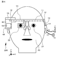
実施例1は、本開示の表示装置に関し、より具体的には、第1の形態の表示装置に関する。実施例1の表示装置の概念図を図1Aに示し、実施例1の表示装置を構成する画像形成装置の画像表示部の模式的な一部断面図を図1Bに示し、実施例1の表示装置を上方から眺めた模式図を図3に示し、実施例1の表示装置を正面から眺めた模式図を図4に示す。また、画像形成装置の画像表示部の一部における画素及び測距素子の配置状態を説明するための模式図を、図8A、図8B、図9A、図9Bに示す。尚、図1A、あるいは、後述する図5A、図5Bにあっては、画像形成装置及び光学系を観察者の上方から眺めている。また、便宜上、観察者の右側の瞳の光学軸に相当する軸線をX軸とし、観察者の右側の瞳と左側の瞳を結ぶ軸線であって、右側の瞳から左側の瞳に向かう軸線をY軸とする。 Example 1 relates to the display device of the present disclosure, and more specifically, relates to the display device of the first aspect. FIG. 1A is a conceptual diagram of the display device according to the first embodiment. FIG. 1B is a schematic partial cross-sectional view of the image display unit of the image forming apparatus constituting the display device according to the first embodiment. FIG. 3 shows a schematic view of the device viewed from above, and FIG. 4 shows a schematic view of the display device of Example 1 viewed from the front. 8A, FIG. 8B, FIG. 9A, and FIG. 9B are schematic diagrams for explaining the arrangement state of pixels and ranging elements in a part of the image display unit of the image forming apparatus. In FIG. 1A, or in FIGS. 5A and 5B described later, the image forming apparatus and the optical system are viewed from above the observer. For convenience, the axis corresponding to the optical axis of the observer's right pupil is the X axis, and the axis connecting the observer's right pupil and the left pupil is the axis extending from the right pupil to the left pupil. The Y axis is assumed.
実施例1の表示装置は、
(イ)観察者20の頭部に装着されるフレーム10、及び、
(ロ)フレーム10に取り付けられた画像表示装置30、
を備えており、
画像表示装置30は、
(A)画像形成装置40、及び、
(B)画像形成装置40からの画像を観察者の瞳に導く光学系50、
を備えている。尚、図示した表示装置にあっては、右眼用画像表示装置30R及び左眼用画像表示装置30Lを備えている両眼タイプの表示装置としたが、右眼用の画像表示装置及び左眼用の画像表示装置の内の一方を備えた片眼タイプの表示装置としてもよい。尚、図4においては、図面の簡素化のため右眼用画像表示装置30Rのみを図示し、左眼用画像表示装置30Lの図示は省略した。
The display device of Example 1 is
(A) the
(B) the
With
The
(A) the
(B) an
It has. In the illustrated display device, a binocular display device including the right-eye
画像形成装置40は、周知の構成、構造を有する複数の発光素子、具体的には、発光ダイオード43が2次元マトリクス状に配列されて成る。そして、画像形成装置40の画像表示部41の内部には測距センサ60が設けられている。具体的には、測距センサ60は複数の測距素子61から構成されており、測距素子61は、画像形成装置40の画像表示部41の画素42の間に配置されている。ここで、画像形成装置40はカラー画像を表示するので、1つの画素42は、赤色を発光する発光ダイオードから構成された赤色発光の副画素42R、緑色を発光する発光ダイオードから構成された緑色発光の副画素42G、及び、青色を発光する発光ダイオードから構成された青色発光の副画素42Bから構成されている。
The
より具体的には、図1Bに示すように、測距素子61は、シリコン半導体基板44に周知の方法で形成された、周知の構成、構造を有するフォトダイオードから成る。また、チップ化された発光ダイオード43は、シリコン半導体基板44に形成された配線45に、例えば、半田バンプ46を介して取り付けられている。尚、取り付けの方法は、これに限定するものではない。
More specifically, as shown in FIG. 1B, the
そして、図8A、図8Bに示すように、1つの測距素子61が、1つの画素42に対応して画素42に隣接して設けられている。あるいは又、図9A、図9Bに示すように、1つの測距素子61が、複数の画素42に対応して画素42に隣接して設けられている。尚、図8A及び図9Aに示す例においては、撮像素子71が画像形成装置40の画像表示部の内部に設けられており、図8Aに示す例では、1つの画素42に対して1つの撮像素子71が設けられており、図9Aに示す例では、画素42の一部には撮像素子71が設けられていない。即ち、図8Aに示す例では、1つの画素42に1つの測距素子61及び1つの撮像素子71が設けられている。また、図8Bに示す例では、1つの画素42に1つの測距素子61が設けられているが、撮像素子71は設けられていない。更には、図9Aに示す例では、複数の画素42の1つに対して1つの測距素子61を設け、残りの画素42のそれぞれに対して1つの撮像素子71を設けている。また、図9Bに示す例では、複数の画素42の1つに対して1つの測距素子61を設け、残りの画素42には測距素子61及び撮像素子71が設けられていない。周知の構成、構造を有する撮像素子71も、測距素子61と同様に、周知の方法に基づきシリコン半導体基板44に形成されている。尚、チップ化された撮像素子を、シリコン半導体基板44に形成された配線に、例えば、半田バンプを介して取り付けてもよい。
8A and 8B, one
実施例1の表示装置において、光学系50は、
(B−1)画像形成装置40からの画像が入射するレンズ51、及び、
(B−2)レンズ51を通過した画像を反射し、観察者20の瞳21に導く半透過鏡52、
を備えている。レンズ51は、周知の構成、構造を有する液体レンズから成る。尚、レンズ51と半透過鏡52との間に、光路を変更するための反射鏡53が配置されている。
In the display device of Example 1, the
(B-1) a
(B-2) a
It has. The
そして、実施例1において、測距センサ60は、画像形成装置40から、レンズ51、反射鏡53及び半透過鏡52を経由した、観察者20の瞳21の網膜までの距離を測定する。そして、レンズ51の焦点距離は、測距センサ60によって測定された距離に基づき制御される。距離の測定方法は、周知のコントラスト方式を採用してもよいし、位相差方式を採用してもよいし、対となった測距素子61によって得られる像のズレに基づき距離を測定する方式を採用することもできる。具体的には、画像形成装置40から、レンズ51、反射鏡53及び半透過鏡52を経由して、観察者20の瞳21の網膜に画像が到達するが、逆に、観察者20の瞳21の網膜の像が、半透過鏡52、反射鏡53及びレンズ51を経由して、画像形成装置40の画像表示部41の内部に設けられた測距センサ60において得られる。即ち、得られた観察者20の瞳21の網膜の像が合焦状態であるか否かを測距センサ60において調べることで、画像形成装置40によって表示される画像が観察者20に合焦状態で到達しているか否かを容易に検証することができる。そして、得られた網膜の像が合焦状態となるように、レンズ51の焦点距離の制御を行う。こうして、画像形成装置40によって表示される画像が、表示装置の使用者(観察者20)に合焦状態で到達していることを保証することができる。尚、参照番号22は仮想投影面を示す。画像形成装置によって表示される画像であって観察者が観察する画像(虚像)が、この仮想投影面22上において観察者によって観察される。
In the first embodiment, the
実施例1にあっては、画像形成装置40から観察者20の瞳21の網膜までの距離の測定を、例えば、60画像表示フレームに1回(即ち、1/60秒に1回)、行うが、このような回数に限定するものではなく、例えば、120画像表示フレームに1回、240画像表示フレームに1回とすることもできる。図6Aに、実施例1の表示装置の動作を説明するための図を示すが、観察者20の網膜までの距離の測定及びレンズ51の焦点距離の制御は、画像形成装置40において画像を表示している間に行う。
In the first embodiment, the distance from the
図2A及び図2Bに、実施例1の表示装置の変形例の概念図を示す。図2Aに示す例にあっては、反射鏡53が省略され、レンズ51から出射した画像は、半透過鏡52に、直接、衝突する。尚、図2Aにあっては、画像形成装置40及び光学系50を観察者の上方から眺めており、画像形成装置40は、観察者の頭部の右側方に配置されている。図2Bに示す例にあっては、反射鏡53が省略され、レンズ51から出射した画像は、半透過鏡52に、直接、衝突する。尚、図2Bにあっては、画像形成装置40及び光学系50を観察者の側方から眺めており、画像形成装置40及びレンズ51は半透過鏡52の上方に配置されている。
2A and 2B are conceptual diagrams of modified examples of the display device according to the first embodiment. In the example shown in FIG. 2A, the reflecting
フレーム10は、観察者20の正面に配置されるフロント部11と、フロント部11の両端に蝶番12を介して回動自在に取り付けられた2つのテンプル部13と、各テンプル部13の先端部に取り付けられたモダン部(先セル、耳あて、イヤーパッドとも呼ばれる)14から成る。また、ノーズパッド(図示せず)が取り付けられている。即ち、フレーム10及びノーズパッドの組立体は、基本的には、通常の眼鏡と略同じ構造を有する。更には、画像形成装置40及びレンズ51を格納し、反射鏡53が取り付けられた筐体48が、取付け部材19によって、着脱自在に、テンプル部13に取り付けられている。半透過鏡52がフロント部11に取り付けられている。フレーム10は、金属又はプラスチックから作製されている。尚、筐体48は、取付け部材19によってテンプル部13に着脱できないように取り付けられていてもよい。眼鏡を所有し、装着している観察者に対しては、観察者の所有する眼鏡のフレームのテンプル部に、筐体48を取付け部材19によって着脱自在に取り付けてもよい。筐体48を、テンプル部13の外側に取り付けてもよいし、テンプル部13の内側に取り付けてもよい。
The
一方の画像形成装置40から延びる配線(信号線や電源線等)15が、テンプル部13、及び、モダン部14の内部を介して、モダン部14の先端部から外部に延び、制御装置(制御回路、制御手段)18に接続されている。更には、画像形成装置40はヘッドホン部16を備えており、画像形成装置40から延びるヘッドホン部用配線17が、テンプル部13、及び、モダン部14の内部を介して、モダン部14の先端部からヘッドホン部16へと延びている。ヘッドホン部用配線17は、より具体的には、モダン部14の先端部から、耳介(耳殻)の後ろ側を回り込むようにしてヘッドホン部16へと延びている。このような構成にすることで、ヘッドホン部16やヘッドホン部用配線17が乱雑に配置されているといった印象を与えることがなく、すっきりとした表示装置とすることができる。
A wiring 15 (a signal line, a power supply line, etc.) 15 extending from one
レンズ51は、エレクトロウェッティング現象を利用した周知の液体レンズ100から構成されている。
The
液体レンズの原理を、図12A、図12B、図12C、図13A、図13B、図13Cの原理図を参照して説明する。尚、図12Aは、図12Bの矢印A−Aに沿った模式的な断面図であり、図12Bは、図12Aの矢印B−Bに沿った模式的な断面図(但し、第1の液体の図示は省略)であり、図12C、図13A、図13B、図13Cは、図12Aの矢印C−Cに沿った模式的な断面図である。尚、液体レンズのxy平面で切断したときの形状は模式的な形状であり、実際の形状とは異なっている。 The principle of the liquid lens will be described with reference to the principle diagrams of FIGS. 12A, 12B, 12C, 13A, 13B, and 13C. 12A is a schematic cross-sectional view taken along the arrow AA in FIG. 12B, and FIG. 12B is a schematic cross-sectional view taken along the arrow BB in FIG. 12A (however, the first liquid 12C, FIG. 13A, FIG. 13B, and FIG. 13C are schematic cross-sectional views along the arrow CC in FIG. 12A. The shape of the liquid lens when cut along the xy plane is a schematic shape and is different from the actual shape.
図12A、図12B、図12C、図13A、図13B、図13Cに原理図を示す液体レンズ(便宜上、『原理的液体レンズ』と呼ぶ)は、ハウジングを備えている。このハウジングは、
第1側面部材101、
第1側面部材101と対向した第2側面部材102、
第1側面部材101の一端部と第2側面部材102の一端部とを結ぶ第3側面部材103、
第1側面部材101の他端部と第2側面部材102の他端部とを結ぶ第4側面部材104、
第1側面部材101、第2側面部材102、第3側面部材103及び第4側面部材104の頂面に取り付けられた天板105、及び、
第1側面部材101、第2側面部材102、第3側面部材103及び第4側面部材104の底面に取り付けられた底板106、
から成り、このハウジングによって1つのレンズ室が構成されている。レンズ室は、軸線が第1側面部材101及び第2側面部材102の延びる方向(z方向)に延びる円柱レンズとしての液体レンズを構成する第1の液体115及び第2の液体116によって占められている。
12A, 12B, 12C, FIG. 13A, FIG. 13B, and FIG. 13C each have a housing (referred to as “principal liquid lens” for the sake of convenience). This housing
A
A
A
A
A
The lens chamber is constituted by this housing. The lens chamber is occupied by the
そして、天板105の部分の内面には、液体レンズを構成する第1電極(以下、単に、『第1電極111』と呼ぶ)が設けられており、第1側面部材101の内面には、液体レンズを構成する第2電極(以下、単に、『第2電極112』と呼ぶ)が設けられており、第2側面部材102の内面には、液体レンズを構成する第3電極(以下、単に、『第3電極113』と呼ぶ)が設けられている。ここで、図12A、図12B、図12Cに示す状態にあっては、第1電極111、第2電極112、第3電極113には電圧を印加していない。
A first electrode constituting a liquid lens (hereinafter simply referred to as “
この状態から、第1電極111、第2電極112、第3電極113に適切な電圧を印加すると、図13A、図13Bあるいは図13Cに示す状態に第1の液体115と第2の液体116の界面の状態が変化する。ここで、図13Aに示す状態は、第2電極112と第3電極113に同じ電圧を印加したときの状態を示し、レンズ室内で形成される液体レンズのxy平面で切断したときの形状は、光軸OAに対して対称である。また、図13B及び図13Cに示す状態は、第2電極112と第3電極113に異なる電圧を印加したときの状態を示し、レンズ室内で形成される液体レンズのxy平面で切断したときの形状は、光軸OAに対して非対称である。尚、第2電極112と第3電極113との間の電位差は、図13Cに示す状態の方が、図13Bに示す状態よりも大きい。図13B及び図13Cに示すように、第2電極112と第3電極113との間の電位差に応じて、液体レンズの光学パワーを変化させることができるし、液体レンズの光軸OA(点線で表示する)をz方向と直交するy方向に移動させることができる。あるいは又、これらの原理図に示す液体レンズを複数、並置し、各液体レンズの第2電極112と第3電極113に印加する電圧を適切に制御することで、液体レンズ全体としての光軸を移動させることができるし、液体レンズ全体としての光軸の傾きを変化させることができるし、液体レンズ全体としてフレネルレンズを構成することができる。
From this state, when appropriate voltages are applied to the
実施例1における実用的な液体レンズ100の模式的な断面図を、図14及び図15A、図15B、図15Cに示す。尚、図14は、図12Bの矢印A−Aに沿ったと同様の模式的な断面図であり、図15A、図15B、図15Cは、図14の矢印C−Cに沿った模式的な断面図である。また、図14の矢印B−Bに沿った模式的な断面図は、図12Bに示したと同様である。
14 and 15A, 15B, and 15C are schematic cross-sectional views of a practical
液体レンズ100は、
(A)第1側面部材101、
第1側面部材101と対向した第2側面部材102、
第1側面部材101の一端部と第2側面部材102の一端部とを結ぶ第3側面部材103、
第1側面部材101の他端部と第2側面部材102の他端部とを結ぶ第4側面部材104、
第1側面部材101、第2側面部材102、第3側面部材103及び第4側面部材104の頂面に取り付けられた天板105、及び、
第1側面部材101、第2側面部材102、第3側面部材103及び第4側面部材104の底面に取り付けられた底板106、
を備えたハウジング100A、並びに、
(B)それぞれが、第1側面部材101と第2側面部材102との間に平行に配置された、(M−1)個の隔壁部材107、
を備えている。
The
(A) the
A
A
A
A
A
A
(B) (M-1)
It has.
そして、実施例1における液体レンズ100にあっては、M個(=5個)のレンズ室108(1081,1082,1083,1084,1085)が並置されている。ここで、各レンズ室108(1081,1082,1083,1084,1085)は、軸線が隔壁部材107の延びる方向と平行な方向(z方向)である円柱レンズとしての液体レンズを構成する第1の液体115及び第2の液体116によって占められている。
In the
第1番目のレンズ室1081は、第1側面部材101、第3側面部材103、第1番目の隔壁部材107、第4側面部材104、天板105、及び、底板106から構成されている。そして、第1番目のレンズ室1081を構成する天板105の部分の内面には、第1電極111が設けられており、第1番目のレンズ室1081を構成する第1側面部材101の部分の内面には、第2電極112が設けられており、第1番目のレンズ室1081を構成する第1番目の隔壁部材107の部分の内面には、第3電極113が設けられている。
The
また、第(m+1)番目のレンズ室108(m+1)は、第m番目(但し、m=1,2・・・M−2)の隔壁部材107、第3側面部材103、第(m+1)番目の隔壁部材107、第4側面部材104、天板105、及び、底板106から構成されている。そして、第(m+1)番目のレンズ室108(m+1)を構成する天板105の部分の内面には、第1電極111が設けられており、第(m+1)番目のレンズ室108(m+1)を構成する第m番目の隔壁部材107の部分の内面には、第2電極112が設けられており、第(m+1)番目のレンズ室108(m+1)を構成する第(m+1)番目の隔壁部材107の部分の内面には、第3電極113が設けられている。
The (m + 1)
更には、第M番目のレンズ室108M(=1085)は、第(M−1)番目の隔壁部材107、第3側面部材103、第2側面部材102、第4側面部材104、天板105、及び、底板106から構成されている。そして、第M番目のレンズ室108M(=1085)を構成する天板105の部分の内面には、第1電極111が設けられており、第M番目のレンズ室108M(=1085)を構成する第(M−1)番目の隔壁部材107の部分の内面には、第2電極112が設けられており、第M番目のレンズ室108M(=1085)を構成する第2側面部材102の部分の内面には、第3電極113が設けられている。
Further, the M-th lens chamber 108 M (= 108 5 ) includes an (M−1) -
尚、図示した例では、各レンズ室毎に第1電極111が設けられているが、天板105の内面に1枚の第1電極111を設けてもよい。
In the illustrated example, the
実施例1における液体レンズ100にあっては、少なくとも第1の液体115と第2の液体116との界面が位置する第1側面部材101、第2側面部材102及び隔壁部材107のそれぞれの表面には、撥水処理が施されている。また、隔壁部材107の底面は底板106まで延びており、隔壁部材107の頂面は天板105まで延びている。ハウジング100Aの外形形状は、z方向に長辺、y方向に短辺を有する矩形形状である。そして、底板106から光が入射し、天板105から光が出射する。
In the
第1の液体115と第2の液体116とは、不溶、不混合であり、第1の液体115と第2の液体116との界面がレンズ面を構成する。ここで、第1の液体115は導電性を有し、第2の液体116は絶縁性を有し、第1電極111は第1の液体115と接しており、第2電極112は絶縁膜114を介して第1の液体115及び第2の液体116と接しており、第3電極113は絶縁膜114を介して第1の液体115及び第2の液体116と接している。また、天板105、底板106、及び、第1電極111は、液体レンズ100に入射する光に対して透明な材料から構成されている。
The
より具体的には、天板105、底板106、第1側面部材101、第2側面部材102、第3側面部材103、第4側面部材104及び隔壁部材107は、ガラス、あるいは、アクリル系樹脂等の樹脂から作製されている。また、導電性を有する第1の液体115は塩化リチウム水溶液から成り、密度は1.06グラム/cm3であり、屈折率は1.34である。一方、絶縁性を有する第2の液体116はシリコーンオイル(モメンティブ・パフォーマンス・マテリアルズ・ジャパン合同会社製TSF437)から成り、密度は1.02グラム/cm3であり、屈折率は1.49である。また、第1電極111はITOから成り、第2電極112及び第3電極113は、例えば、金、アルミニウム、銅、銀等の金属電極から成る。更には、絶縁膜114は、ポリパラキシレンや酸化タンタル、酸化チタン等の金属酸化物から成る。尚、絶縁膜114の上に撥水処理層(図示せず)が設けられている。撥水処理層はポリパラキシリレンやフッ素系のポリマーから成る。第1電極111の表面に親水処理を施し、第3側面部材103や第4側面部材104の内面に撥水処理を施すことが好ましい。
More specifically, the
そして、実施例1にあっては、レンズ51を構成するために、図14に示した液体レンズ100を2つ、重ね合わせる。具体的には、下側の液体レンズ100のy方向と、上側の液体レンズ100のy方向とが直交するように、しかも、下側の液体レンズ100のz方向と、上側の液体レンズ100のz方向とが直交するように、重ね合わせる。
And in Example 1, in order to comprise the
第1電極111、第2電極112及び第3電極113は、図示しない接続部を介して、制御回路18に接続され、所望の電圧が印加される構成、構造となっている。そして、第1電極111、第2電極112及び第3電極113に電圧を印加すると、第1の液体115と第2の液体116との界面によって構成されたレンズ面が、図15Aに示す下に凸の状態から、図15Bに示す上に凸の状態に向かって変化する。レンズ面の変化状態は、Lippman-Young の式に基づき、電極111,112,113に印加する電圧によって変化する。図15Bに示した例においては、第2電極112と第3電極113に同じ電圧を印加している。それ故、レンズ室内で形成される液体レンズのxy平面で切断したときの形状は、液体レンズの光軸に対して対称である。重ね合わせた2つの液体レンズ100の内、上側の液体レンズ100に対して、このような制御を行えばよい。
The
また、図15Cに示す状態は、第2電極112と第3電極113とに異なる電圧を印加したときの状態を示すが、レンズ室内で形成される液体レンズのxy平面で切断したときの形状は、液体レンズの光軸に対して非対称である。ここで、図15Cに示す状態にあっては、液体レンズ100としてフレネルレンズが構成される。重ね合わせた2つの液体レンズ100の内、上側の液体レンズ100に対して、このような制御を行ってもよい。
The state shown in FIG. 15C shows a state when different voltages are applied to the
第2電極112を共通の配線に接続し、第3電極113を共通の配線に接続し、各第2電極112には同じ電圧を印加し、各第3電極113には同じ電圧を印加する構成とすることができる。あるいは又、第2電極112を共通の配線に接続し、第3電極113を個別の配線に接続して個別に異なる電圧を印加する構成とすることもできるし、第3電極113を共通の配線に接続し、第2電極112を個別の配線に接続して個別に異なる電圧を印加する構成とすることもできるし、第2電極112、第3電極113共、個別の配線に接続して個別に異なる電圧を印加する構成とすることもできる。
A configuration in which the
別の構成の液体レンズ120の模式的な断面図を図16に示し、平面図を図17に示すが、この液体レンズ120はフレネルレンズから構成され、リング状のレンズ室が同心に配置されている。即ち、液体レンズ120は、
(A)終端部を有していない、所謂エンドレスの外壁部材129、
外壁部材129の頂面に取り付けられた天板125、及び、
外壁部材129の底面に取り付けられた底板126、
を備えたハウジング、並びに、
(B)終端部を有しておらず、外壁部材129と同心に配置された(N−1)個の隔壁部材127、
を備えている。尚、ハウジングの外形形状は円形である。そして、(N−1)個の環状レンズ室、及び、第(N−1)番目の隔壁部材127によって囲まれた中央レンズ室を有している。ここで、図示した例にあっては、N=3とした。各レンズ室128(1281.1282,1283)は、液体レンズ120を構成する第1の液体115及び第2の液体116によって占められている。
A schematic cross-sectional view of another configuration of the
(A) a so-called endless
A
A
A housing with
(B) (N-1)
It has. The outer shape of the housing is circular. The center lens chamber is surrounded by (N-1) annular lens chambers and the (N-1)
第1番目のレンズ室(環状レンズ室)1281は、外壁部材129、第1番目の隔壁部材127、天板125、及び、底板126から構成されている。そして、第1番目のレンズ室1281を構成する天板125の部分の内面には、液体レンズ120を構成する第1電極(以下、単に、『第1電極131』と呼ぶ)が設けられており、第1番目のレンズ室1281を構成する外壁部材129の部分の内面には、液体レンズ120を構成する第2電極(以下、単に、『第2電極132』と呼ぶ)が設けられており、第1番目のレンズ室1281を構成する第1番目の隔壁部材127の部分の内面には、液体レンズ120を構成する第3電極(以下、単に、『第3電極133』と呼ぶ)が設けられている。
The first lens chamber (annular lens chamber) 128 1 includes an
第(n+1)番目のレンズ室(環状レンズ室)128(n+1)は、第n番目(但し、n=1,2・・・N−2)の隔壁部材127、第(n+1)番目の隔壁部材127、天板125、及び、底板126から構成されている。そして、第(n+1)番目のレンズ室128(n+1)を構成する天板125の部分の内面には、第1電極131が設けられており、第(n+1)番目のレンズ室128(n+1)を構成する第n番目の隔壁部材127の部分の内面には、第2電極132が設けられており、第(n+1)番目のレンズ室128(n+1)を構成する第(n+1)番目の隔壁部材127の部分の内面には、第3電極133が設けられている。
The (n + 1) th lens chamber (annular lens chamber) 128 (n + 1) has an nth (where n = 1, 2,..., N−2)
第N番目のレンズ室128Nに相当する中央レンズ室1283を構成する天板125の部分の内面には、第1電極131が設けられており、中央レンズ室1283を構成する第(N−1)番目の隔壁部材127の部分の内面には、第3電極133が設けられている。
Part of the inner surface of the
尚、図示した例では、各レンズ室毎に第1電極131が設けられているが、天板125の内面に1枚の第1電極131を設けてもよい。
In the illustrated example, the
この液体レンズ120においては、少なくとも第1の液体115と第2の液体116との界面が位置する外壁部材129及び隔壁部材127のそれぞれの表面には、先に説明した液体レンズ100と同様に、撥水処理が施されている。底板126から光が入射し、天板125から光が出射する。そして、各レンズ室1281,1282,1283において、第2電極132に印加する電圧と第3電極133に印加する電圧とを異ならせることで、液体レンズ120の光学パワーを変化させる。あるいは又、各レンズ室1281,1282,1283において、第2電極132に印加する電圧と第3電極133に印加する電圧とを異ならせることで、液体レンズ全体としてフレネルレンズが構成される。
In the
実施例2は、実施例1の変形であり、第2の形態の表示装置に関する。実施例2の表示装置にあっては、測距センサ60は、画像形成装置40から、観察者20が観察している外部の対象物23までの距離を測定する。レンズ51の焦点距離は、測距センサ60によって測定された距離に基づき制御される。具体的には、図5Aに概念図を示すように、実施例1の表示装置における反射鏡53の代わりに、半透過鏡52とは別の半透過鏡(第2の半透過鏡54)が配置されており、測距センサ60は、画像形成装置40から、第2の半透過鏡54を介して、観察者20が観察している外部の対象物23までの距離を測定する。尚、外部の対象物23は、X軸上に位置しているとする。以上の点を除き、実施例2の表示装置の構成、構造は、実施例1の表示装置の構成、構造と同様とすることができるので、詳細な説明は省略する。尚、図2A、図2Bに示した実施例1の表示装置の変形例において、レンズ51と半透過鏡52の間に、第2の半透過鏡54を配置してもよい。
Example 2 is a modification of Example 1 and relates to the display device of the second mode. In the display device according to the second embodiment, the
更には、観察者20が観察している外部の対象物23に関する情報を画像形成装置40において表示する。外部の対象物23の像を、測距センサ60(具体的には、測距素子61)あるいは撮像素子71によって得た後、得られた像を制御装置(制御回路)18において解析し、対象物23を特定し、制御装置(制御回路)18に記憶された対象物23に関する情報を画像形成装置40において表示すればよい。レンズ51の焦点距離を制御することで、画像形成装置40によって表示される画像であって観察者が観察する画像(虚像)、即ち、観察者20が操作することなく、自動的に、外部の対象物23に関する情報まで距離を、観察者20が観察している外部の対象物23と一致させる(あるいは、概ね一致させる)ことができ、インタラクティブ且つスムーズな虚像と実空間の合成ができるので、画像の観察に違和感が生じることが無い。
Further, the
図6Bに、実施例2の表示装置の動作を説明するための図を示すが、対象物23までの距離の測定及びレンズ51の焦点距離の制御は、画像形成装置40において画像を表示していない間に行うことが好ましい。
FIG. 6B is a diagram for explaining the operation of the display device according to the second embodiment. In the measurement of the distance to the
実施例2の表示装置にあっては、測距センサ60が画像形成装置40の画像表示部の内部に設けられている。それ故、簡素な構成、構造であるにも拘わらず、観察者が観察する外部の対象物までの距離測定を容易に行うことができる。
In the display device according to the second embodiment, the
実施例3も、実施例1の変形であり、第3の形態の表示装置に関する。実施例3の表示装置にあっては、測距センサ60は、レンズ51及び半透過鏡52を介して観察者の視点の検出を行う。即ち、観察者が実空間のどこに視点を置いているかを検出する。そして、検出された観察者20の視点に基づき、画像形成装置40から、観察者20が観察している外部の対象物23までの距離を求める。レンズ51の焦点距離は、測距センサ60によって測定された距離に基づき制御される。具体的には、図5Bに概念図を示すように、実施例1の表示装置における反射鏡53の代わりに、実施例2の表示装置と同様に、第2の半透過鏡54が配置されている。そして、測距センサ60は、レンズ51、第2の半透過鏡54を及び半透過鏡52を介して観察者の視点の検出を行う。また、検出された観察者20の視点に基づき、第2の半透過鏡54及びレンズ51を介して、画像形成装置40から、観察者20が観察している外部の対象物23までの距離を求める。以上の点を除き、実施例3の表示装置の構成、構造は、実施例1の表示装置の構成、構造と同様とすることができるので、詳細な説明は省略する。尚、図2A、図2Bに示した実施例1の表示装置の変形例において、レンズ51と半透過鏡52の間に、第2の半透過鏡54を配置してもよい。
Example 3 is also a modification of Example 1, and relates to the display device of the third mode. In the display device according to the third embodiment, the
更には、実施例2と同様に、観察者20が観察している外部の対象物23に関する情報を画像形成装置40において表示する。レンズ51の焦点距離を制御することで、画像形成装置40によって表示される画像であって観察者20が観察する画像(虚像)、即ち、外部の対象物23に関する情報まで距離を、観察者20が操作することなく、自動的に、観察者20が観察している外部の対象物23と一致させる(あるいは、概ね一致させる)ことができ、インタラクティブ且つスムーズな虚像と実空間の合成ができるので、画像の観察に違和感が生じることが無い。
Further, as in the second embodiment, information related to the
図7に、実施例3の表示装置の動作を説明するための図を示すが、先ず、測距センサ60によって測定された観察者20の眼球表面までの距離を求め、レンズ51の焦点距離を制御することで、レンズ51の焦点を眼球表面に合わせる。次いで、周知の方法で、測距センサ60は、観察者20の視点の検出を行い、その後、測距センサ60は、画像形成装置40から、レンズ51、第2の半透過鏡54を経由して、観察者20が観察している外部の対象物23を測定する。そして、レンズ51の焦点距離を制御した後、画像形成装置40によって画像を表示する。即ち、画像形成装置40において画像を表示していない間に、観察者20の眼球までの距離の測定、観察者20の視点の検出、対象物23までの距離の測定を行う。
FIG. 7 is a diagram for explaining the operation of the display device of Example 3. First, the distance to the eyeball surface of the
実施例3の表示装置にあっても、測距センサ60が画像形成装置40の画像表示部の内部に設けられている。それ故、簡素な構成、構造であるにも拘わらず、観察者20の視点の検出、観察者20が観察する外部の対象物23までの距離測定を容易に行うことができる。
Even in the display apparatus according to the third embodiment, the
実施例4は、実施例1〜実施例3の変形である。実施例4にあっては、画像形成装置40において所定の情報(例えば、入力インターフェース)を表示する。所定の情報は、画像表示部の下部に表示される。また、所定の情報は、例えば、観察者20の1m程度前方の仮想投影面上に投影される。所定の情報の選択(例えば、入力)は、例えば、所定の情報を示す虚像を観察者が指で指す状態を撮像素子71によって撮像し、どの所定の情報の選択を行ったかを制御装置(制御回路)18において解析し、選択された情報に基づいて各種処理を行えばよい。
The fourth embodiment is a modification of the first to third embodiments. In the fourth embodiment, the
実施例5は、実施例1〜実施例4の変形である。図10A、図10B、図10C及び図10Dに、実施例5の表示装置を構成する画像形成装置の画像表示部の概念図を示す。実施例5の表示装置にあっては、発光ダイオード43と測距素子61との間に遮光部材47が配されている。遮光部材47は、発光ダイオード43から出射された光の測距素子61への入射を妨げ得る材料から構成すればよい。このように遮光部材47を設けることで、発光ダイオード43の影響を測距素子61は受け難くなる。
The fifth embodiment is a modification of the first to fourth embodiments. 10A, 10B, 10C, and 10D are conceptual diagrams of an image display unit of an image forming apparatus that constitutes the display device according to the fifth embodiment. In the display device according to the fifth embodiment, the
図10Aに示す例では、シリコン半導体基板44に測距素子61が形成され、シリコン半導体基板44の上に発光ダイオード43が配置され、測距素子61と発光ダイオード43との間に遮光部材47が配されている。図10Bに示す例では、シリコン半導体基板44の上に測距素子61及び発光ダイオード43が配置され、測距素子61と発光ダイオード43との間に遮光部材47が配されている。
In the example shown in FIG. 10A, a
図10Cに示す例では、シリコン半導体基板44に測距センサ60が形成され、シリコン半導体基板44の上に発光ダイオード43が配置され、発光ダイオード43の外側に遮光部材47が設けられている。図10Dに示す例では、シリコン半導体基板44の上に測距センサ60及び発光ダイオード43が配置され、発光ダイオード43の外側に遮光部材47が設けられている。尚、遮光部材は、赤色を発光する発光ダイオードから構成された赤色発光の副画素42R、緑色を発光する発光ダイオードから構成された緑色発光の副画素42G、及び、青色を発光する発光ダイオードから構成された青色発光の副画素42Bのそれぞれに設けてもよいし、3つの副画素42R,42G,42Bの全体(1画素)に対して設けてもよい。
In the example shown in FIG. 10C, the
更には、測距素子61、発光ダイオード43、遮光部材47の全体を封止してもよい。尚、実施例1〜実施例4において、測距素子61及び発光ダイオード43の全体を封止してもよい。
Furthermore, the entire
実施例6は、実施例1〜実施例5の変形である。図11A及び図11Bの模式図に、実施例6の表示装置を構成する画像形成装置の画像表示部の一部における画素及び測距素子の配置例を示すが、実施例6にあっては、画素に隣接して配置された測距素子61の受光波長を、隣接する副画素の発光波長と異ならせる。これによって、光学的クロストークを低減させることができる。具体的には、測距素子61にカラーフィルタを配置すればよい。より具体的には、赤色発光の副画素42Rに隣接して緑色あるいは青色を受光する測距素子61G,61Bを設ければよいし、緑色発光の副画素42Gに隣接して赤色あるいは青色を受光する測距素子61R,61Bを設ければよいし、青色発光の副画素42Bに隣接して赤色あるいは緑色を受光する測距素子61R,61Gを設ければよい。
The sixth embodiment is a modification of the first to fifth embodiments. FIG. 11A and FIG. 11B are schematic diagrams illustrating an arrangement example of pixels and ranging elements in a part of an image display unit of an image forming apparatus that constitutes the display device of the sixth embodiment. In the sixth embodiment, The light receiving wavelength of the
以上、本開示を好ましい実施例に基づき説明したが、本開示はこれらの実施例に限定するものではない。実施例において説明した表示装置(頭部装着型ディスプレイ)、画像表示装置、測距センサ、液体レンズの構成、構造は例示であり、適宜変更することができるし、発光素子や測距センサ、撮像素子の配置も例示で有り、適宜、変更することができる。場合によっては、測距センサを撮像素子としても用いることもできる。実施例において、画像形成装置40を構成する発光素子を、専ら、発光ダイオードとしたが、これに限定されるものではなく、その他、例えば、有機エレクトロルミネッセンス素子(有機EL素子)や、液晶表示素子から構成することもでき、この場合、半導体基板の上に形成された層間絶縁層上にこれらの素子を形成すればよい。
Although the present disclosure has been described based on the preferred embodiments, the present disclosure is not limited to these embodiments. The configurations and structures of the display device (head-mounted display), the image display device, the distance sensor, and the liquid lens described in the embodiments are examples, and can be changed as appropriate. The light emitting element, the distance sensor, and the imaging The arrangement of elements is also an example, and can be changed as appropriate. In some cases, the distance measuring sensor can also be used as an image sensor. In the embodiments, the light-emitting elements constituting the
尚、本開示は、以下のような構成を取ることもできる。
[A01]《表示装置》
(イ)観察者の頭部に装着されるフレーム、及び、
(ロ)フレームに取り付けられた画像表示装置、
を備えており、
画像表示装置は、
(A)画像形成装置、及び、
(B)画像形成装置からの画像を観察者の瞳に導く光学系、
を備えており、
画像形成装置の画像表示部の内部には、測距センサが設けられている表示装置。
[A02]測距センサは複数の測距素子から構成されており、
測距素子は、画像形成装置の画像表示部の画素間に配置されている[A01]に記載の表示装置。
[A03]光学系は、
(B−1)画像形成装置からの画像が入射するレンズ、及び、
(B−2)レンズを通過した画像を反射し、観察者の瞳に導く半透過鏡、
を備えている[A01]又は[A02]に記載の表示装置。
[A04]レンズは液体レンズから成る[A03]に記載の表示装置。
[A05]液体レンズの焦点距離は、測距センサによって測定された距離に基づき制御される[A04]に記載の表示装置。
[B01]測距センサは、画像形成装置から、レンズ及び半透過鏡を経由した、観察者の網膜までの距離を測定する[A03]又は[A04]に記載の表示装置。
[B02]レンズの焦点距離は、測距センサによって測定された距離に基づき制御される[B01]に記載の画像表示装置。
[B03]レンズの焦点距離を制御することで、画像形成装置によって表示される画像を、合焦状態で観察者に到達させる[B01]又は[B02]に記載の表示装置。
[B04]観察者の網膜までの距離の測定は、画像形成装置において画像を表示している間に行う[B01]乃至[B03]のいずれか1項に記載の表示装置。
[C01]測距センサは、画像形成装置から、観察者が観察している外部の対象物までの距離を測定する[A03]又は[A04]に記載の表示装置。
[C02]光学系は、更に、レンズと半透過鏡との間に第2の半透過鏡を備えている[C01]に記載の表示装置。
[C03]レンズの焦点距離は、測距センサによって測定された距離に基づき制御される[C01]又は[C02]に記載の画像表示装置。
[C04]観察者が観察している外部の対象物に関する情報を画像形成装置において表示する[C01]乃至[C03]のいずれか1項に記載の表示装置。
[C05]レンズの焦点距離を制御することで、画像形成装置によって表示される画像であって観察者が観察する画像である虚像まで距離を、観察者が観察している外部の対象物と一致させ、あるいは、概ね一致させる[C01]乃至[C04]のいずれか1項に記載の画像表示装置。
[C06]対象物までの距離の測定は、画像形成装置において画像を表示していない間に行う[C01]乃至[C05]のいずれか1項に記載の画像表示装置。
[D01]測距センサは、レンズ及び半透過鏡を介して観察者の視点の検出を行い、検出された観察者の視点に基づき、画像形成装置から、観察者が観察している外部の対象物までの距離を求める[A03]又は[A04]に記載の表示装置。
[D02]光学系は、更に、レンズと半透過鏡との間に第2の半透過鏡を備えている[D01]に記載の表示装置。
[D03]レンズの焦点距離は、測距センサによって測定された距離に基づき制御される[D01]又は[D02]に記載の画像表示装置。
[D04]観察者が観察している外部の対象物に関する情報を画像形成装置において表示する[D01]乃至[D03]のいずれか1項に記載の表示装置。
[D05]レンズの焦点距離を制御することで、画像形成装置によって表示される画像であって観察者が観察する画像である虚像まで距離を、観察者が観察している外部の対象物と一致させ、あるいは、概ね一致させる[D01]乃至[D04]のいずれか1項に記載の画像表示装置。
[D06]観察者の視点の検出、対象物までの距離の測定は、画像形成装置において画像を表示していない間に行う[D01]乃至[D05]のいずれか1項に記載の画像表示装置。
[D07]観察者の視点の検出を行う前に、測距センサは、画像形成装置から、レンズ及び半透過鏡を経由した、観察者の眼球表面までの距離を測定し、次いで、測距センサによって測定された眼球表面までの距離に基づきレンズの焦点距離を制御する[D01]乃至[D06]のいずれか1項に記載の画像表示装置。
[D08]観察者の眼球表面までの距離の測定を、観察者の視点の検出の前であって、画像形成装置において画像を表示していない間に行う[D07]に記載の画像表示装置。
[E01]画像形成装置において所定の情報を表示する[A01]乃至[D08]のいずれか1項に記載の表示装置。
[E02]所定の情報は、画像表示部の下部に表示される[E01]に記載の表示装置。
[E03]画像形成装置は、複数の発光ダイオードが2次元マトリクス状に配列されて成る[A01]乃至[E02]のいずれか1項に記載の表示装置。
[E04]発光ダイオードと測距センサを構成する測距素子との間には遮光部材が配されている[E03]に記載の表示装置。
[E05]画素に隣接して設けられた測距素子の受光波長は、隣接する画素の発光波長と異なる[A01]乃至[E04]のいずれか1項に記載の表示装置。
In addition, this indication can also take the following structures.
[A01] << Display device >>
(A) a frame to be worn on the observer's head; and
(B) an image display device attached to the frame;
With
The image display device
(A) an image forming apparatus, and
(B) an optical system for guiding an image from the image forming apparatus to the pupil of the observer;
With
A display device in which a distance measuring sensor is provided inside an image display unit of the image forming apparatus.
[A02] The distance measuring sensor is composed of a plurality of distance measuring elements,
The distance measuring element is the display device according to [A01] arranged between pixels of an image display unit of the image forming apparatus.
[A03] The optical system is
(B-1) a lens on which an image from the image forming apparatus is incident, and
(B-2) a semi-transmissive mirror that reflects the image that has passed through the lens and guides it to the observer's pupil;
The display device according to [A01] or [A02].
[A04] The display device according to [A03], wherein the lens is a liquid lens.
[A05] The display device according to [A04], in which a focal length of the liquid lens is controlled based on a distance measured by a distance measuring sensor.
[B01] The display device according to [A03] or [A04], wherein the distance measuring sensor measures a distance from the image forming apparatus to the retina of the observer via the lens and the semi-transparent mirror.
[B02] The image display device according to [B01], wherein the focal length of the lens is controlled based on a distance measured by a distance measuring sensor.
[B03] The display device according to [B01] or [B02], in which an image displayed by the image forming apparatus is made to reach an observer in a focused state by controlling a focal length of the lens.
[B04] The display device according to any one of [B01] to [B03], wherein the measurement of the distance to the retina of the observer is performed while an image is displayed on the image forming apparatus.
[C01] The display device according to [A03] or [A04], in which the distance measuring sensor measures a distance from the image forming apparatus to an external object observed by an observer.
[C02] The display device according to [C01], in which the optical system further includes a second semi-transmissive mirror between the lens and the semi-transmissive mirror.
[C03] The image display device according to [C01] or [C02], in which a focal length of the lens is controlled based on a distance measured by a distance measuring sensor.
[C04] The display device according to any one of [C01] to [C03], wherein information related to an external object being observed by an observer is displayed on the image forming apparatus.
[C05] By controlling the focal length of the lens, the distance to the virtual image, which is an image displayed by the image forming apparatus and observed by the observer, matches the external object that the observer observes. Or the image display device according to any one of [C01] to [C04].
[C06] The image display device according to any one of [C01] to [C05], wherein the measurement of the distance to the object is performed while the image is not displayed in the image forming apparatus.
[D01] The distance measuring sensor detects an observer's viewpoint through a lens and a semi-transparent mirror, and based on the detected observer's viewpoint, an external object that the observer observes from the image forming apparatus The display device according to [A03] or [A04] for obtaining a distance to an object.
[D02] The display device according to [D01], in which the optical system further includes a second semi-transmissive mirror between the lens and the semi-transmissive mirror.
[D03] The image display device according to [D01] or [D02], in which a focal length of the lens is controlled based on a distance measured by a distance measuring sensor.
[D04] The display device according to any one of [D01] to [D03], wherein information related to an external object being observed by an observer is displayed on the image forming apparatus.
[D05] By controlling the focal length of the lens, the distance to the virtual image, which is an image displayed by the image forming apparatus and observed by the observer, matches the external object that the observer observes. Or [D01] to [D04] according to any one of [D01] to [D04].
[D06] The image display device according to any one of [D01] to [D05], wherein the detection of the observer's viewpoint and the measurement of the distance to the object are performed while the image is not displayed on the image forming apparatus. .
[D07] Before detecting the observer's viewpoint, the distance measurement sensor measures the distance from the image forming apparatus to the eyeball surface of the observer via the lens and the semi-transparent mirror, and then the distance measurement sensor. The image display device according to any one of [D01] to [D06], wherein the focal length of the lens is controlled based on the distance to the eyeball surface measured by.
[D08] The image display device according to [D07], in which the distance to the eyeball surface of the observer is measured before the observer's viewpoint is detected and while the image is not displayed on the image forming apparatus.
[E01] The display device according to any one of [A01] to [D08], which displays predetermined information in the image forming apparatus.
[E02] The display device according to [E01], wherein the predetermined information is displayed at a lower portion of the image display unit.
[E03] The image forming apparatus according to any one of [A01] to [E02], in which a plurality of light emitting diodes are arranged in a two-dimensional matrix.
[E04] The display device according to [E03], wherein a light shielding member is disposed between the light emitting diode and the distance measuring element constituting the distance measuring sensor.
[E05] The display device according to any one of [A01] to [E04], in which a light receiving wavelength of a distance measuring element provided adjacent to the pixel is different from a light emitting wavelength of the adjacent pixel.
10・・・フレーム、11・・・フロント部、12・・・蝶番、13・・・テンプル部、14・・・モダン部、15・・・配線(信号線や電源線等)、16・・・ヘッドホン部、17・・・ヘッドホン部用配線、18・・・制御装置(制御回路)、19・・・取付け部材、20・・・観察者、21・・・観察者の瞳、22・・・仮想投影面、23・・・外部の対象物、30・・・画像表示装置、40・・・画像形成装置、41・・・画像表示部、42・・・画素、42R,42G,42B・・・副画素、43・・・発光ダイオード、44・・・シリコン半導体基板、45・・・配線、46・・・半田バンプ、47・・・遮光部材、48・・・筐体、50・・・光学系、51・・・レンズ、52・・・半透過鏡、53・・・反射鏡、54・・・第2の半透過鏡、60・・・測距センサ(距離センサ)、61・・・測距素子、71・・・撮像素子、100,120・・・液体レンズ、101・・・第1側面部材、102・・・第2側面部材、103・・・第3側面部材、104・・・第4側面部材、105・・・天板、106・・・底板、107・・・隔壁部材、111・・・液体レンズを構成する第1電極、112・・・液体レンズを構成する第2電極、113・・・液体レンズを構成する第3電極、114・・・絶縁膜、115・・・第1の液体、116・・・第2の液体、125・・・天板、126・・・底板、127・・・隔壁部材、128,1281.1282,1283・・・レンズ室、129・・・外壁部材、131・・・液体レンズを構成する第1電極、132・・・液体レンズを構成する第2電極、133・・・液体レンズを構成する第3電極
DESCRIPTION OF
Claims (16)
(ロ)フレームに取り付けられた画像表示装置、
を備えており、
画像表示装置は、
(A)画像形成装置、及び、
(B)画像形成装置からの画像を観察者の瞳に導く光学系、
を備えており、
画像形成装置の画像表示部の内部には、測距センサが設けられている表示装置。 (A) a frame to be worn on the observer's head; and
(B) an image display device attached to the frame;
With
The image display device
(A) an image forming apparatus, and
(B) an optical system for guiding an image from the image forming apparatus to the pupil of the observer;
With
A display device in which a distance measuring sensor is provided inside an image display unit of the image forming apparatus.
測距素子は、画像形成装置の画像表示部の画素間に配置されている請求項1に記載の表示装置。 The ranging sensor is composed of multiple ranging elements.
The display device according to claim 1, wherein the distance measuring element is disposed between pixels of an image display unit of the image forming apparatus.
(B−1)画像形成装置からの画像が入射するレンズ、及び、
(B−2)レンズを通過した画像を反射し、観察者の瞳に導く半透過鏡、
を備えている請求項1に記載の表示装置。 The optical system
(B-1) a lens on which an image from the image forming apparatus is incident, and
(B-2) a semi-transmissive mirror that reflects the image that has passed through the lens and guides it to the observer's pupil;
The display device according to claim 1, comprising:
Priority Applications (3)
| Application Number | Priority Date | Filing Date | Title |
|---|---|---|---|
| JP2013139503A JP2015015520A (en) | 2013-07-03 | 2013-07-03 | Display device |
| CN201410294540.5A CN104280882B (en) | 2013-07-03 | 2014-06-26 | Display system and display methods |
| US14/315,386 US9846303B2 (en) | 2013-07-03 | 2014-06-26 | Display system having display device and sensor on substrate |
Applications Claiming Priority (1)
| Application Number | Priority Date | Filing Date | Title |
|---|---|---|---|
| JP2013139503A JP2015015520A (en) | 2013-07-03 | 2013-07-03 | Display device |
Publications (1)
| Publication Number | Publication Date |
|---|---|
| JP2015015520A true JP2015015520A (en) | 2015-01-22 |
Family
ID=52132442
Family Applications (1)
| Application Number | Title | Priority Date | Filing Date |
|---|---|---|---|
| JP2013139503A Pending JP2015015520A (en) | 2013-07-03 | 2013-07-03 | Display device |
Country Status (3)
| Country | Link |
|---|---|
| US (1) | US9846303B2 (en) |
| JP (1) | JP2015015520A (en) |
| CN (1) | CN104280882B (en) |
Cited By (1)
| Publication number | Priority date | Publication date | Assignee | Title |
|---|---|---|---|---|
| KR20230039886A (en) | 2021-09-14 | 2023-03-22 | 한국생산기술연구원 | Active nitrogen oxide and sulfur oxide reduction system to reduce combustion emission materials and nitrogen oxide and sulfur oxide reduction method using the same |
Families Citing this family (3)
| Publication number | Priority date | Publication date | Assignee | Title |
|---|---|---|---|---|
| JP6532393B2 (en) * | 2015-12-02 | 2019-06-19 | 株式会社ソニー・インタラクティブエンタテインメント | Display control apparatus and display control method |
| TWI609713B (en) * | 2017-04-14 | 2018-01-01 | 緯創資通股份有限公司 | Retractable virtual reality device |
| WO2019017513A1 (en) * | 2017-07-20 | 2019-01-24 | Lg Electronics Inc. | Head-mounted display and method of controlling the same |
Family Cites Families (12)
| Publication number | Priority date | Publication date | Assignee | Title |
|---|---|---|---|---|
| JPH09274144A (en) * | 1996-04-02 | 1997-10-21 | Canon Inc | Image display device |
| US6867752B1 (en) * | 1998-08-31 | 2005-03-15 | Semiconductor Energy Laboratory Co., Ltd. | Portable information processing system |
| JP2005164978A (en) * | 2003-12-03 | 2005-06-23 | Nikon Corp | Head mounted display |
| WO2005104234A1 (en) * | 2004-04-19 | 2005-11-03 | Hitachi, Ltd. | Image pickup function solid type display device |
| JP2010073841A (en) | 2008-09-18 | 2010-04-02 | Sony Corp | Optical package element, display device, and electronic apparatus |
| JP2010139901A (en) | 2008-12-15 | 2010-06-24 | Brother Ind Ltd | Head mount display |
| US20130278631A1 (en) * | 2010-02-28 | 2013-10-24 | Osterhout Group, Inc. | 3d positioning of augmented reality information |
| US20120212484A1 (en) * | 2010-02-28 | 2012-08-23 | Osterhout Group, Inc. | System and method for display content placement using distance and location information |
| US8994611B2 (en) * | 2010-03-24 | 2015-03-31 | Olympus Corporation | Head-mounted type display device |
| JP5499854B2 (en) * | 2010-04-08 | 2014-05-21 | ソニー株式会社 | Optical position adjustment method for head mounted display |
| US9304319B2 (en) * | 2010-11-18 | 2016-04-05 | Microsoft Technology Licensing, Llc | Automatic focus improvement for augmented reality displays |
| US20130300635A1 (en) * | 2012-05-09 | 2013-11-14 | Nokia Corporation | Method and apparatus for providing focus correction of displayed information |
-
2013
- 2013-07-03 JP JP2013139503A patent/JP2015015520A/en active Pending
-
2014
- 2014-06-26 US US14/315,386 patent/US9846303B2/en active Active
- 2014-06-26 CN CN201410294540.5A patent/CN104280882B/en active Active
Cited By (1)
| Publication number | Priority date | Publication date | Assignee | Title |
|---|---|---|---|---|
| KR20230039886A (en) | 2021-09-14 | 2023-03-22 | 한국생산기술연구원 | Active nitrogen oxide and sulfur oxide reduction system to reduce combustion emission materials and nitrogen oxide and sulfur oxide reduction method using the same |
Also Published As
| Publication number | Publication date |
|---|---|
| US9846303B2 (en) | 2017-12-19 |
| CN104280882B (en) | 2018-12-11 |
| US20150009101A1 (en) | 2015-01-08 |
| CN104280882A (en) | 2015-01-14 |
Similar Documents
| Publication | Publication Date | Title |
|---|---|---|
| JP6202117B2 (en) | Display device | |
| JP6690550B2 (en) | Optical device and display device | |
| JP6391952B2 (en) | Display device and optical device | |
| JP5434848B2 (en) | Display device | |
| CN104950443B (en) | Light element, image display device and display equipment | |
| JP6123342B2 (en) | Display device | |
| US10514542B2 (en) | Head-mounted display | |
| JP5790187B2 (en) | Display device | |
| JP6872136B2 (en) | Image display device, display device, and adjustment method of display device | |
| JP2015184561A (en) | Light guide device, image display device, and display device | |
| JP2011221235A (en) | Optical position adjusting method in head-mounted display | |
| JP2007086500A (en) | Display device | |
| CN108702500A (en) | Display device, the method and electronic equipment for driving display device | |
| JP2015015520A (en) | Display device | |
| JP2015135447A (en) | Video projection device, and head-mounted display | |
| CN107148591A (en) | Display device and display control method | |
| JP2010098567A (en) | Head mount full-face type image display device | |
| JP5793099B2 (en) | Display device, electronic device and control circuit | |
| US10718949B1 (en) | Display apparatus and method of displaying | |
| JP5786910B2 (en) | Optical position adjustment method for head mounted display | |
| US20230314716A1 (en) | Emission of particular wavelength bands utilizing directed wavelength emission components in a display system | |
| CN117492210A (en) | Glasses and working method thereof |