JP2014532379A - Data transmission control - Google Patents
Data transmission control Download PDFInfo
- Publication number
- JP2014532379A JP2014532379A JP2014536000A JP2014536000A JP2014532379A JP 2014532379 A JP2014532379 A JP 2014532379A JP 2014536000 A JP2014536000 A JP 2014536000A JP 2014536000 A JP2014536000 A JP 2014536000A JP 2014532379 A JP2014532379 A JP 2014532379A
- Authority
- JP
- Japan
- Prior art keywords
- communication
- application
- wireless device
- data
- related parameter
- Prior art date
- Legal status (The legal status is an assumption and is not a legal conclusion. Google has not performed a legal analysis and makes no representation as to the accuracy of the status listed.)
- Pending
Links
Images


Classifications
-
- H—ELECTRICITY
- H04—ELECTRIC COMMUNICATION TECHNIQUE
- H04L—TRANSMISSION OF DIGITAL INFORMATION, e.g. TELEGRAPHIC COMMUNICATION
- H04L47/00—Traffic control in data switching networks
- H04L47/10—Flow control; Congestion control
- H04L47/18—End to end
-
- H—ELECTRICITY
- H04—ELECTRIC COMMUNICATION TECHNIQUE
- H04L—TRANSMISSION OF DIGITAL INFORMATION, e.g. TELEGRAPHIC COMMUNICATION
- H04L47/00—Traffic control in data switching networks
- H04L47/10—Flow control; Congestion control
- H04L47/22—Traffic shaping
- H04L47/225—Determination of shaping rate, e.g. using a moving window
-
- H—ELECTRICITY
- H04—ELECTRIC COMMUNICATION TECHNIQUE
- H04L—TRANSMISSION OF DIGITAL INFORMATION, e.g. TELEGRAPHIC COMMUNICATION
- H04L47/00—Traffic control in data switching networks
- H04L47/10—Flow control; Congestion control
- H04L47/24—Traffic characterised by specific attributes, e.g. priority or QoS
- H04L47/2475—Traffic characterised by specific attributes, e.g. priority or QoS for supporting traffic characterised by the type of applications
-
- H—ELECTRICITY
- H04—ELECTRIC COMMUNICATION TECHNIQUE
- H04L—TRANSMISSION OF DIGITAL INFORMATION, e.g. TELEGRAPHIC COMMUNICATION
- H04L47/00—Traffic control in data switching networks
- H04L47/10—Flow control; Congestion control
- H04L47/25—Flow control; Congestion control with rate being modified by the source upon detecting a change of network conditions
-
- H—ELECTRICITY
- H04—ELECTRIC COMMUNICATION TECHNIQUE
- H04W—WIRELESS COMMUNICATION NETWORKS
- H04W24/00—Supervisory, monitoring or testing arrangements
- H04W24/08—Testing, supervising or monitoring using real traffic
-
- H—ELECTRICITY
- H04—ELECTRIC COMMUNICATION TECHNIQUE
- H04W—WIRELESS COMMUNICATION NETWORKS
- H04W28/00—Network traffic management; Network resource management
- H04W28/02—Traffic management, e.g. flow control or congestion control
- H04W28/0215—Traffic management, e.g. flow control or congestion control based on user or device properties, e.g. MTC-capable devices
-
- H—ELECTRICITY
- H04—ELECTRIC COMMUNICATION TECHNIQUE
- H04W—WIRELESS COMMUNICATION NETWORKS
- H04W28/00—Network traffic management; Network resource management
- H04W28/02—Traffic management, e.g. flow control or congestion control
- H04W28/0252—Traffic management, e.g. flow control or congestion control per individual bearer or channel
-
- H—ELECTRICITY
- H04—ELECTRIC COMMUNICATION TECHNIQUE
- H04W—WIRELESS COMMUNICATION NETWORKS
- H04W28/00—Network traffic management; Network resource management
- H04W28/02—Traffic management, e.g. flow control or congestion control
- H04W28/0284—Traffic management, e.g. flow control or congestion control detecting congestion or overload during communication
-
- H—ELECTRICITY
- H04—ELECTRIC COMMUNICATION TECHNIQUE
- H04W—WIRELESS COMMUNICATION NETWORKS
- H04W28/00—Network traffic management; Network resource management
- H04W28/02—Traffic management, e.g. flow control or congestion control
- H04W28/10—Flow control between communication endpoints
-
- H—ELECTRICITY
- H04—ELECTRIC COMMUNICATION TECHNIQUE
- H04W—WIRELESS COMMUNICATION NETWORKS
- H04W28/00—Network traffic management; Network resource management
- H04W28/16—Central resource management; Negotiation of resources or communication parameters, e.g. negotiating bandwidth or QoS [Quality of Service]
- H04W28/18—Negotiating wireless communication parameters
- H04W28/22—Negotiating communication rate
-
- H—ELECTRICITY
- H04—ELECTRIC COMMUNICATION TECHNIQUE
- H04W—WIRELESS COMMUNICATION NETWORKS
- H04W8/00—Network data management
- H04W8/02—Processing of mobility data, e.g. registration information at HLR [Home Location Register] or VLR [Visitor Location Register]; Transfer of mobility data, e.g. between HLR, VLR or external networks
- H04W8/04—Registration at HLR or HSS [Home Subscriber Server]
-
- H—ELECTRICITY
- H04—ELECTRIC COMMUNICATION TECHNIQUE
- H04L—TRANSMISSION OF DIGITAL INFORMATION, e.g. TELEGRAPHIC COMMUNICATION
- H04L47/00—Traffic control in data switching networks
- H04L47/10—Flow control; Congestion control
- H04L47/30—Flow control; Congestion control in combination with information about buffer occupancy at either end or at transit nodes
Landscapes
- Engineering & Computer Science (AREA)
- Computer Networks & Wireless Communication (AREA)
- Signal Processing (AREA)
- Databases & Information Systems (AREA)
- Quality & Reliability (AREA)
- Mobile Radio Communication Systems (AREA)
Abstract
一実施形態では、無線装置から、通信チャンネルを介して接続された受信器へのデータ伝送を制御する方法は、無線装置上で実行されているアプリケーションが、通信チャンネルのエンドツーエンドの帯域幅の推定を提供するステップと、無線装置中の無線アクセス回路から、アプリケーションに、少なくとも一通信関連パラメータを供給するステップと、アプリケーションにおいて、少なくとも一通信関連パラメータを用いて、エンドツーエンド帯域幅の推定を修正するステップとを有する。In one embodiment, a method for controlling data transmission from a wireless device to a receiver connected via a communication channel allows an application running on the wireless device to control the end-to-end bandwidth of the communication channel. Providing at least one communication-related parameter to the application from a radio access circuit in the wireless device; and using the at least one communication-related parameter in the application to provide end-to-end bandwidth estimation. Modifying.
Description
本発明は、無線装置から受信器へのデータ送信の制御に関する。 The present invention relates to control of data transmission from a wireless device to a receiver.
図1は、第1のユーザ端末UE1と第2のユーザ端末UE2とを有する通信システムを示すブロック図である。第1と第2のユーザ端末は、通信ネットワーク2により通信している。第1と第2のユーザ端末間に通信を提供するため、それらの間に通信チャンネル設定する。このチャンネルは、第1のユーザ端末とネットワーク間の区間(leg)と、ネットワーク自体にわたる区間と、ネットワークと第2のユーザ端末間の区間とを有する。各区間は有線でも無線でもよく、無線接続は例として示す。通信ネットワークはパケットスイッチでもよく、すなわち第1のユーザ端末から第2のユーザ端末に送信されるデータは、それらの間に設定される通信チャンネルにより搬送されるパケットの形式を取る。 FIG. 1 is a block diagram showing a communication system having a first user terminal UE1 and a second user terminal UE2. The first and second user terminals communicate via the communication network 2. In order to provide communication between the first and second user terminals, a communication channel is set between them. This channel has a leg between the first user terminal and the network, a section over the network itself, and a section between the network and the second user terminal. Each section may be wired or wireless, and wireless connection is shown as an example. The communication network may be a packet switch, i.e. the data transmitted from the first user terminal to the second user terminal takes the form of a packet carried by a communication channel set between them.
データフローを試み改善し、輻輳を最小化し、効率を上げるため、かかる伝送にはレートコントロールが広く使われている。すなわち、データが送信側(送信器)から送信されるレートは、データが送信される利用可能帯域幅に関する情報に基づき制御される。レート制御に対する一アプローチは、エンドツーエンドレート制御である。エンドツーエンドレート制御は、異なる複数の形式で実装できるが、原理的には、送信側(送信器)と受信側(受信器)との間の端から端までに存在するチャンネルに関する情報に依存する。エンドツーエンドレート制御のどの実装においても、送信器からのメッセージが受信器に届かなければならず、そのメッセージに関する情報(またはそのメッセージ自体)が受信器から送信器にラウンドトリップで返される。エンドツーエンドレート制御には、通信チャンネルの最小ボトルネックがどこにあるかにということについて仮定をしないという利点がある。他方、ボトルネックで輻輳が始まると、受信器においてこれを検出して、送信者にメッセージを返さなければならない。そのため、輻輳への対応には少なくともラウンドトリップタイム(RTT)かかり、その間に輻輳はひどくなり、リアルタイム通信体験を損なうおそれもある。 Rate control is widely used for such transmissions to try and improve data flow, minimize congestion and increase efficiency. That is, the rate at which data is transmitted from the transmission side (transmitter) is controlled based on information about the available bandwidth at which the data is transmitted. One approach to rate control is end-to-end rate control. End-to-end rate control can be implemented in different formats, but in principle depends on information about the channel that exists between the sender (transmitter) and the receiver (receiver). To do. In any implementation of end-to-end rate control, a message from the transmitter must reach the receiver, and information about the message (or the message itself) is returned from the receiver to the transmitter in a round trip. End-to-end rate control has the advantage of making no assumptions about where the smallest bottleneck of the communication channel is. On the other hand, if congestion begins at the bottleneck, this must be detected at the receiver and a message returned to the sender. Therefore, it takes at least a round trip time (RTT) to cope with the congestion, during which the congestion becomes severe and the real-time communication experience may be impaired.
本発明の一目的は、エンドツーエンドレート制御の利点を有しつつ、応答時間を改善するデータ送信の制御手法を提供することである。 One object of the present invention is to provide a data transmission control technique that improves the response time while having the advantages of end-to-end rate control.
本発明の一態様による方法は、無線装置から、通信チャンネルを介して接続された受信器へのデータ伝送を制御する方法であって、前記無線装置上で実行されているアプリケーションが、前記通信チャンネルのエンドツーエンドの帯域幅の推定を提供するステップと、前記無線装置中の無線アクセス回路から、前記アプリケーションに、少なくとも一通信関連パラメータを供給するステップと、前記アプリケーションにおいて、前記少なくとも一通信関連パラメータを用いて、前記エンドツーエンド帯域幅の推定を修正するステップとを有する。 A method according to an aspect of the invention is a method for controlling data transmission from a wireless device to a receiver connected via a communication channel, wherein an application running on the wireless device is the communication channel. Providing at least one communication-related parameter to the application from a radio access circuit in the wireless device; and in the application, providing the at least one communication-related parameter. To correct the end-to-end bandwidth estimation.
実行されたとき、上記の方法を実施するプログラムコード手段を有するコンピュータプログラム製品も提供される。 Also provided is a computer program product having program code means for performing the above method when executed.
ここで、「エンドツーエンド帯域幅」との用語は、送信元と最終的宛先との間の帯域幅を推定する場合に限定されない。この場合、エンドツーエンド帯域幅は、通信ネットワーク自体でインテリジェントオペレーションが実行されるモデルとは対照的に、通信システムのエンドポイントにおいていわゆるインテリジェントオペレーションが行われる場合に関する。エンドツーエンドの原理は、現在のインターネットの中心的設計原理のひとつであり、他の多くのネットワーク通信システムに適用される。エンドツーエンドの原理の利点は、ネットワークがそれを通る各トラフィックフローの状態を保持する必要が無く、ネットワーク設計がより単純かつロバストになることにある。 Here, the term “end-to-end bandwidth” is not limited to estimating the bandwidth between the source and the final destination. In this case, the end-to-end bandwidth relates to the case where so-called intelligent operations are performed at the end points of the communication system as opposed to the model in which intelligent operations are performed in the communication network itself. The end-to-end principle is one of the core design principles of the current Internet and is applied to many other network communication systems. The advantage of the end-to-end principle is that the network design does not need to maintain the state of each traffic flow through it, making the network design simpler and more robust.
特に、エンドツーエンド帯域幅は、送信器、受信器、またはその送信器と最終的受信器との間にあるオーバーレイ/リレーノードを含むエンドポイントを含む。
本発明の他の位置態様によるプロセッサは、
無線チャンネルにより受信器にデータを送信する無線装置で用いるプロセッサと、プロセッサで実行されると、アプリケーションを構成して、通信チャンネルのエンドツーエンド帯域幅の推定を提供するステップと、無線アクセス回路から少なくとも一通信関連パラメータを受け取るステップと、前記少なくとも一通信関連パラメータを用いて前記エンドツーエンド帯域幅の推定を修正するステップとを実行するプログラムコード手段を有するコンピュータプログラム製品とを有する。
In particular, end-to-end bandwidth includes an endpoint that includes a transmitter, a receiver, or an overlay / relay node between that transmitter and the final receiver.
A processor according to another position aspect of the present invention comprises:
A processor for use in a wireless device that transmits data to a receiver over a wireless channel, and, when executed on the processor, configures an application to provide an end-to-end bandwidth estimate of the communication channel; A computer program product comprising program code means for performing at least one communication related parameter and modifying the end-to-end bandwidth estimate using the at least one communication related parameter.
以下に説明する本発明の実施形態は、エンドツーエンドレート制御の利点を、無線アクセスレベルにおけるローカルモニタリングと組み合わせる。すなわち、ここに説明するローカルキュー支援レート制御により、エンドポイントがレート制御をでき、ネットワークは決定する必要がない。発明者は、多くの場合、通信チャンネルにおいて、無線アクセス技術、特にそのアップリンクが最も弱いリンクであり、輻輳源になりやすいことを知っている。無線アクセスレベルにおける通信関連パラメータ、特にバッファ状態インジケータを監視し、アプリケーションレイヤに通知することにより、エンドツーエンドレート制御の利点を、無線アクセスレベルにおける情報に基づく素早い反応と組み合わせることができる。このように、以下に説明する実施形態では、ローカルバッファにおける変化に直ちに反応でき、一方で、ボトルネックがローカル無線アップリンクのどこか別の場所にあるとき、エンドツーエンドレート制御を維持する。 The embodiments of the invention described below combine the benefits of end-to-end rate control with local monitoring at the radio access level. That is, the local queue support rate control described here allows the endpoint to perform rate control, and the network need not be determined. The inventor often knows that, in communication channels, radio access technology, especially its uplink, is the weakest link and is likely to be a source of congestion. By monitoring communication-related parameters at the radio access level, particularly the buffer status indicator, and notifying the application layer, the benefits of end-to-end rate control can be combined with a quick response based on information at the radio access level. Thus, the embodiments described below can react immediately to changes in the local buffer, while maintaining end-to-end rate control when the bottleneck is somewhere else on the local radio uplink.
エンドツーエンド帯域幅推定は、送信器側でも受信器側でもよい。すなわち、アプリケーションは、例えば、送信器などのリモート装置からのフィードバックに基づいて、おそらくリモート装置または受信器からのアクノレッジメントの返信率を測定しローパスフィルタする形式で、(送信側の)無線装置においてエンドツーエンド帯域幅の推定を生成すると考えられる。 The end-to-end bandwidth estimation may be on the transmitter side or the receiver side. That is, the application is terminated at the wireless device (on the sending side), for example in the form of measuring and low-pass filtering the acknowledgment response rate from the remote device or receiver based on feedback from a remote device such as a transmitter. It is thought to generate a two-end bandwidth estimate.
あるいは、エンドツーエンド帯域幅の推定を受信側で実行して、アプリケーションを、リモート装置または受信器からエンドツーエンド帯域幅の推定を受信するように構成できる。 Alternatively, end-to-end bandwidth estimation can be performed at the receiver to configure the application to receive end-to-end bandwidth estimation from a remote device or receiver.
このように、無線アクセス回路に設けられたローカルバッファを常に監視して、輻輳を検知したらすぐにアプリケーションに通知することにより、輻輳に直ちに反応することができる。無線アクセスレベルからのフィードバックは、そのレベルにおけるバッファキュー状態の直接測定であってもよいので、エンドツーエンドの遅延ベースのレート制御の基礎になるキューイング推定よりもずっと信頼性が高い。後者はクロックオフセット問題とWiFiビーコン検索などのネットワークアーティファクトにより汚染され得るからである。 In this way, the local buffer provided in the wireless access circuit is always monitored, and notification is made to the application as soon as congestion is detected, so that it is possible to react immediately to the congestion. Since feedback from the radio access level may be a direct measurement of the buffer queue state at that level, it is much more reliable than the queuing estimate that underlies end-to-end delay-based rate control. This is because the latter can be polluted by clock artifacts and network artifacts such as WiFi beacon search.
本発明をよく理解し、どのように実施するか示すため、以下の図面を参照する。 For a better understanding of the present invention and how to implement it, reference is made to the following drawings.
以下、本発明の実施形態を説明するが、無線パケットスイッチ通信システム(GPRS、UMTS、HSDPA、Wimax、LTE、Wifiなど)では、送信側は物理的(ネットワーク)レイヤの送信待ちトラフィック量を常に監視している。物理レイヤのこのバッファされたデータに関する情報は、アプリケーションレイヤに送られ、レート制御の改善に用いられる。具体的に、一実施形態では、かかる情報をエンドツーエンドレート制御といかに組み合わせて、よりアジャイルなレート制御器を作るか示す。 Hereinafter, embodiments of the present invention will be described. In a radio packet switch communication system (GPRS, UMTS, HSDPA, Wimax, LTE, WiFi, etc.), the transmission side constantly monitors the traffic waiting for transmission in the physical (network) layer. doing. Information about this buffered data in the physical layer is sent to the application layer and used to improve rate control. In particular, one embodiment shows how such information can be combined with end-to-end rate control to create a more agile rate controller.
図2は、本発明の基礎をなす原理を示す概略ブロック図である。アプリケーションレイヤの処理コードにより実装された帯域幅変更機能(bandwidth modification function)は、アプリケーションレイヤで実行されたアプリケーションから、一般的にはそのアプリケーションのレート制御部から、帯域幅BW−e2eの推定を受け取り、さらに無線アクセスを担う下位プロトコルレイヤから通信関連パラメータd(k)、c(k)及びs(k)を受け取る。この変更機能により帯域幅BW(k)を変更した推定が与えられる。 FIG. 2 is a schematic block diagram illustrating the principle underlying the present invention. The bandwidth modification function implemented by the application layer processing code receives an estimate of the bandwidth BW-e2e from the application executed at the application layer, typically from the application's rate controller. Further, communication related parameters d (k), c (k) and s (k) are received from the lower protocol layer responsible for radio access. This change function gives an estimate of changing the bandwidth BW (k).
本発明の概略的状況を図2Aを参照して説明する。送信器4は、インターネット2などのパケットベースネットワークにより、受信器6にリアルタイムデータ(例えば、オーディオ及び/またはビデオ)を送る。送信器4は、UMTS、HSDPA、Wimax、LTE、Wifiなどの無線アクセス技術を用いて、インターネットにアクセスする。一方、受信器6はどの技術(有線または無線)でも用いられる。 The general situation of the present invention will be described with reference to FIG. 2A. The transmitter 4 sends real-time data (eg, audio and / or video) to the receiver 6 over a packet-based network such as the Internet 2. The transmitter 4 accesses the Internet using a radio access technology such as UMTS, HSDPA, Wimax, LTE, and WiFi. On the other hand, the receiver 6 can be used with any technology (wired or wireless).
送信器は無線装置であり、マイクロプロセッサ8を含む。マイクロプロセッサ8は、それ自体に、またはそれに接続されたメモリにローカルに記憶されたコード形式のプログラムを実行する。無線装置4は、無線装置4とネットワーク2との間で無線周波数(RF)通信を送受信する無線アクセスチップ10を有する。
The transmitter is a wireless device and includes a microprocessor 8. The microprocessor 8 executes a program in the form of a code stored on its own or locally in a memory connected thereto. The wireless device 4 includes a
無線装置4とネットワーク2との間のRF通信は、無線アクセスチップ10により無線チャンネルによりRF信号を送受信することにより行われる。
RF communication between the wireless device 4 and the network 2 is performed by transmitting and receiving an RF signal through a wireless channel by the
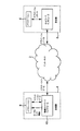
無線装置は、例えば、GPRS、UMTS、HSDPA、Wimax、LTEまたはWifiなどの少なくとも一無線アクセス技術をサポートするユーザ装置(UE)であり得る。プロセッサにより実行されるソフトウェアは、図3に示したタイプのプロトコルスタックで構成される。図3はスタックの単なる一例を示すものである。現在使われている多くのバリエーションがあり、本発明はどのタイプのスタックにも適用できる。図3に例示したスタックは、アプリケーションレイヤ12、トランスポートレイヤ14、インターネットレイヤ16、及びリンクレイヤ18を含む。リンクレイヤは、物理リンクレイヤ20とメディアアクセスコントロール(MAC)レイヤ22に分かれる。
The wireless device may be a user equipment (UE) that supports at least one radio access technology such as, for example, GPRS, UMTS, HSDPA, Wimax, LTE, or WiFi. The software executed by the processor comprises a protocol stack of the type shown in FIG. FIG. 3 shows just one example of a stack. There are many variations currently in use and the present invention can be applied to any type of stack. The stack illustrated in FIG. 3 includes an
リンクレイヤは、装置4の通信技術の構成を担うものである。リンクレイヤ18中のメディアアクセスコントロールレイヤ22は、なかんずく、アドレッシング、複数のチャンネルの異なるユーザへの割り当て、及び輻輳の防止の機能を担う。具体的には、無線の動作モードの制御を担う。メディアアクセスコントロールレイヤ22は、送信するデータをキューイングするバッファと、監視回路を含むが、後でもっと詳しく説明する。各レイヤは、異なる無線装置中の自分と同じレイヤと通信でき、リンクレイヤ18は、フレームの形式のRFデータのレベルにおいて、異なる装置の対応するリンクレイヤと通信する。
The link layer is responsible for the configuration of the communication technology of the device 4. The media
インターネットレイヤは、IP(Internet Protocol)ヘッダを有するIPデータを運ぶパケットの形式でインターネット通信を提供し、IPアドレッシングを担う。 The Internet layer provides Internet communication in the form of packets carrying IP data having an IP (Internet Protocol) header and is responsible for IP addressing.
トランスポートレイヤ14は、例えば、トランスミッションコントロールプロトコル(TCP)またはユーザデータグラムプロトコル(UDP)によりホストツーホスト通信を実行する。この場合、ホストは無線通信をしようとする任意の種類のユーザ装置である。
The
アプリケーションレイヤ12は、通信しているホスト間のプロセスツープロセスレベルにおけるアプリケーションベースのインターラクションを処理する。チャンネルにより送信されるデータを生成するのは、ユーザアプリケーションを実行するのはこのレイヤである。このように、メディアアクセスコントロールレイヤ22を通して少なくとも一無線アクセス技術により、インターネット2に接続するユーザ装置が、少なくとも一アプリケーションを実行する場合における本発明の実施形態を説明した。
The
本発明は、複数の異なるアプリケーションと用いることができるが、具体的なある場合は、UE間のVoIP(Voice over Internet Protocol)、インスタントメッセージング(IM)チャット、または会議フレームワーク上で実行されるライブミーティングなどのソーシャルコミュニケーションに関する。アプリケーションは、これらの種類のサービスとともに、ファイル転送などのデータ転送、ソーシャルネットワーク中のコンタクトのプレゼンス情報の更新、または「キープアライブ」データなどの制御データを担い得る。 The present invention can be used with a number of different applications, but in certain cases, live over a Voice over Internet Protocol (VoIP), Instant Messaging (IM) chat between UEs, or live on a conference framework. Concerning social communication such as meetings. With these types of services, an application may be responsible for data transfer such as file transfer, updating contact presence information in a social network, or control data such as “keep alive” data.
好ましくは、インターネットによりリアルタイムデータを送信するアプリケーションは、エンドツーエンドレート制御方式が実装されており、リアルタイムデータのコーディングレートを決定する。このエンドツーエンド方式は、文献Jacobson, V.著「Congestion Avoidance and Control」(ACM Computer Communications Review,18(4):314―329、August1988)に記載されているような、本技術分野で知られた任意の方法であってもよい。かかる方式は一般的に2つのカテゴリーに入る:
・受信器ベースは、受信側がデータの受信に基づき、エンドツーエンド接続に用いる適当な帯域幅を推定するものである。
・送信器ベースは、送信側が受信器からフィードバックされる特殊なフィードバックに基づき、用いる帯域幅を決定するものである。
Preferably, an application that transmits real-time data via the Internet is implemented with an end-to-end rate control scheme and determines the coding rate of the real-time data. This end-to-end scheme is known in the art, as described in the document “Congestion Avoidance and Control” by Jacobson, V. (ACM Computer Communications Review, 18 (4): 314-329, August 1988). Any method may be used. Such schemes generally fall into two categories:
The receiver base estimates the appropriate bandwidth for the end-to-end connection based on the reception of data by the receiver.
The transmitter base determines the bandwidth to be used based on special feedback fed back from the receiver.
どちらの場合でも、アプリケーションにより提供されるエンドツーエンドの帯域幅の推定をBW_e2eと呼ぶ。エンドツーエンドレート制御が基づく情報は、受信器から送信器までネットワークを送られなければならない。そのため、遅延が生じる。このように、ネットワーク経路上のどこかで輻輳が発生した場合、それに対する送信器の反応は遅くなり、輻輳問題は悪化する。 In either case, the end-to-end bandwidth estimation provided by the application is referred to as BW_e2e. Information based on end-to-end rate control must be sent from the receiver to the transmitter over the network. Therefore, a delay occurs. Thus, if congestion occurs somewhere on the network path, the transmitter's response to it becomes slow and the congestion problem is exacerbated.
他のしかし好ましくはない実施形態では、エンドツーエンド推定は単純に直近の送信レートに等しくても良いが、ボトルネックがどこかにある場合、かかるアプローチには問題がある。 In other but less preferred embodiments, end-to-end estimation may simply be equal to the most recent transmission rate, but such an approach is problematic when the bottleneck is somewhere.
発明者は、多くの場合、通信経路において、無線アクセス技術、特にそのアップリンクが最も弱いリンクであり、輻輳源になりやすいことを知っている。この輻輳は、リアルタイムアプリケーション実行中に、同じ装置またはコンピュータにおける、しかし異なるネットワークレイヤにおける、パケットキューの発生(a build-up of a packet queue)として現れる。説明した本発明の実施形態では、下位ネットワークレイヤ20、22は、アプリケーションレイヤに、自レイヤの内部バッファの状態または無線レベルでモニタされたその他の通信関連パラメータに関して通知し続ける。この情報は、次のパラメータのうちの一または複数のパラメータを含み得る:
・時間単位(d(k))、バイト単位(N(k))などの現在のバッファサイズ。これら2つは、関係N(k)=d(k)*R(k)により互換性がある。ここでR(k)は直近の送信レートである。そこで、以下d(k)としても一般性は失わない。
・専用の輻輳表示パラメータc(k)。
・アンテナ信号対雑音比(SNR)などのs(k)。
・他のアプリケーションにより送信されたトラフィックの表示であって、例えば、Xtr(k)=tr_0(k)/tr_tot(k)、ここで、tr_0はアプリケーション自体の送信レートであって、tr_totはすべてのアプリケーションの総送信レートであり、kはカウンティングインデックスである。この情報は所定時間間隔で、または好ましくは適応的に供給され、輻輳などの至急情報が、それが発生するとすぐにアプリケーションレイヤに与えられる。
The inventor knows that, in many cases, the radio access technology, especially its uplink, is the weakest link in the communication path and is likely to be a source of congestion. This congestion manifests as a build-up of a packet queue at the same device or computer but at different network layers during real-time application execution. In the described embodiment of the invention, the lower network layers 20, 22 keep informing the application layer about the state of its own internal buffer or other communication-related parameters monitored at the radio level. This information may include one or more of the following parameters:
The current buffer size in units of time (d (k)), bytes (N (k)), etc. These two are compatible by the relationship N (k) = d (k) * R (k). Here, R (k) is the latest transmission rate. Therefore, the generality is not lost even when d (k) is used.
A dedicated congestion display parameter c (k).
S (k) such as antenna signal-to-noise ratio (SNR).
An indication of traffic sent by other applications, eg Xtr (k) = tr_0 (k) / tr_tot (k), where tr_0 is the transmission rate of the application itself and tr_tot is all The total transmission rate of the application, and k is a counting index. This information is provided at predetermined time intervals, or preferably adaptively, and urgent information such as congestion is provided to the application layer as soon as it occurs.
上記のパラメータの時間平均を使うこともできる。 A time average of the above parameters can also be used.
c(k)の実施例として、d(k)が所定閾値を超えたときc(k)=1と設定し、d(k)がそれより低い他の閾値より低くなったとき、c(k)=0に戻す。 As an example of c (k), when d (k) exceeds a predetermined threshold, c (k) = 1 is set, and when d (k) becomes lower than another lower threshold, c (k) ) = 0.
より低いネットワークレイヤから供給される情報を用いて、エンドツーエンド帯域幅推定を修正する。例えば、これらのパラメータを用いて、エンドツーエンド帯域幅に相関項を見つけることができる: The information supplied from the lower network layer is used to modify the end-to-end bandwidth estimation. For example, using these parameters, a correlation term can be found in the end-to-end bandwidth:

好ましい実施形態では、f()を用いる: In a preferred embodiment, f () is used:
d_aggr(k)の計算については、多くのオプションがある。一般的に、値は急激な変化を避けるようになめらかでなければならないが、輻輳が生じたときにはすぐに反応できなければならない。これは、適応的平滑化により達成できる。図4は、合成された瞬間値d_inst(k)の平滑化を示す概略的ブロック図である。合成されたオブザベーションd_inst(k)は、合成関数40により生成され、平滑化関数42により平滑化される。平滑化値d_aggr(k)は、現在の瞬間的オブザベーションd_inst(k)より小さければ、すばやく更新される。そうでなければ、ゆっくりと更新される。数学的には、これは次の式で表せる:
There are many options for calculating d_aggr (k). In general, the value should be smooth to avoid sudden changes, but should be able to react quickly when congestion occurs. This can be achieved by adaptive smoothing. FIG. 4 is a schematic block diagram illustrating smoothing of the synthesized instantaneous value d_inst (k). The synthesized observation d_inst (k) is generated by the
合成オブザベーションd_inst(k)は、d(k)、c(k)及びs(k)のうちの一部または全部の瞬間値を合成することにより生成できる。例えば:
・リンクレイヤから直接レポートされる平均キュー遅延を用いる:
The synthesized observation d_inst (k) can be generated by synthesizing some or all of the instantaneous values of d (k), c (k), and s (k). For example:
Use the average queue delay reported directly from the link layer:
ここで、d_cの合理的な値は、例えば、150msである。
好ましい実施形態では、s(k)を考慮して、信号品質が悪化すると、大きなステップを用いる:
Here, a reasonable value of d_c is, for example, 150 ms.
In the preferred embodiment, taking into account s (k), if the signal quality deteriorates, a large step is used:
いくつかの場合では、パラメータd(k)、c(k)及びs(k)のうちすべてが得られるわけではない。この場合、得られないパラメータを0に設定すれば、上記の式を直接用いることができる。しかし、大幅に改良するため、d(k)またはc(k)の少なくとも一方が得られなければならない:これらはバッファ状態インジケータと呼べる。ネットワークレイヤ18におけるトラフィック輻輳に関係するからである。
In some cases, not all of the parameters d (k), c (k) and s (k) are obtained. In this case, if a parameter that cannot be obtained is set to 0, the above formula can be used directly. However, to improve significantly, at least one of d (k) or c (k) must be obtained: these can be called buffer status indicators. This is because it relates to traffic congestion in the
上記の方法の潜在的な問題は、同じ環境で実行されている他のアプリケーションがフィードバックを聞いてなく、輻輳に反応しないかも知れないことである。かかるアプリケーションは、正しく反応しているアプリケーションから利用可能なすべての帯域幅を徐々に奪ってしまうおそれがある。それゆえ、好ましい実施形態では、Xtr(k)も考慮する。こうする一方法は、式(2)のalpha(k)をXtr(k)に依存させることである。例えば、上記の示唆の通りXtr(k)=tr_0(k)/tr_tot(k)である場合: A potential problem with the above method is that other applications running in the same environment may not hear feedback and respond to congestion. Such an application may gradually deprive all available bandwidth from a correctly responding application. Therefore, in the preferred embodiment, Xtr (k) is also considered. One way to do this is to make alpha (k) in equation (2) dependent on Xtr (k). For example, if Xtr (k) = tr_0 (k) / tr_tot (k) as suggested above:
帯域幅適応関数44は、ローカルリンク情報でe2e BWの推定を処理して、データ送信レートの設定に用いるアプリケーションの帯域幅の修正推定値を供給する。
The
言うまでもなく、上記の式は、単なる例示的実施形態であり、多くの変形が可能である。同様に、図5に示すように、パラメータ平滑化ステップと合成ステップを交換して、合成関数56とBW適応関数58の前に、個別の平滑化関数50、42、54を各パラメータに適用する。
Of course, the above equations are merely exemplary embodiments, and many variations are possible. Similarly, as shown in FIG. 5, the parameter smoothing step and the synthesis step are exchanged, and the individual smoothing functions 50, 42, and 54 are applied to the respective parameters before the
図6は、本発明の実施形態の実装に関連するコンポーネントのみを示す無線アクセスチップ10を示す概略的ブロック図である。このチップは、RF処理回路を有するアンテナ66を提供する。アンテナ66によりチップ10はRFデータを送受信できる。上記のように、かかるデータは、エンドツーエンド帯域幅推定を用いてレートを制御するとき、フィードバック及び/または帯域幅の推定を含み得る。また、データには、通信チャンネルにより伝送される、アプリケーションレイヤからのデータを含み得る。このチップは、バッファ60とモニタリング回路64も含むように例示されている。モニタリング回路64は、通信チャンネルの無線状態例えば信号対雑音比を監視して、パラメータs(k)を与える。チップ10は、バッファ状態インジケータd(k)に基づいて特殊輻輳インジケータc(k)を生成するロジックも含む。チップ10と装置の他のレイヤとの間の接続は、チップに入る及びチップから出る矢印によって模式的に示した。かかる接続を実際にどう実装して、送信するデータをアプリケーションから受け取り、リンクレイヤ18のチップ10からアプリケーションレイヤ12のアプリケーションまで通信関連パラメータを供給するかは、明らかである。
FIG. 6 is a schematic block diagram illustrating a
Claims (10)
前記無線装置上で実行されているアプリケーションが、前記通信チャンネルのエンドツーエンドの帯域幅の推定を提供するステップと、
前記アプリケーションが、前記無線装置中の無線アクセス回路から、少なくとも一通信関連パラメータを受け取るステップと、
前記アプリケーションにおいて、前記少なくとも一通信関連パラメータを用いて、前記エンドツーエンド帯域幅の推定を修正するステップと
を有する方法。 A method for controlling data transmission from a wireless device to a receiver connected via a communication channel, comprising:
An application running on the wireless device providing an end-to-end bandwidth estimate of the communication channel;
The application receiving at least one communication related parameter from a radio access circuit in the wireless device;
Modifying the end-to-end bandwidth estimate using the at least one communication-related parameter in the application.
前記無線アクセス回路のバッファ中のデータ量の表示と、
輻輳インジケータパラメータと、
前記無線アクセス回路により決定された無線信号品質パラメータと
のうちの一を含む、請求項1に記載の方法。 The at least one communication related parameter is:
An indication of the amount of data in the buffer of the wireless access circuit;
A congestion indicator parameter;
The method of claim 1, comprising one of radio signal quality parameters determined by the radio access circuit.
請求項2に記載の方法。 The at least one communication related parameter includes an indication of the amount of data in the buffer of the wireless access circuit, and the indication includes at least one of a time indication or a bit;
The method of claim 2.
前記無線装置において、エンドツーエンド帯域幅の推定を生成し、または、
リモート装置からエンドツーエンド帯域幅の推定を受け取るように構成されている、
請求項1ないし7いずれか一項に記載の方法。 The application is
Generating an end-to-end bandwidth estimate in the wireless device; or
Configured to receive an end-to-end bandwidth estimate from a remote device;
8. A method according to any one of the preceding claims.
前記プロセッサにロードされたアプリケーションは、無線アクセス回路から少なくとも一通信関連パラメータを受け取り、前記少なくとも一通信関連パラメータを用いて前記エンドツーエンド帯域幅の推定を修正するように動作可能である、プロセッサ。 A processor loaded with an application that operates to provide an end-to-end bandwidth estimation of a communication channel between the wireless device and the receiver for use in a wireless device that transmits data to a receiver over a wireless channel Because
An application loaded into the processor is operable to receive at least one communication-related parameter from a radio access circuit and to modify the end-to-end bandwidth estimate using the at least one communication-related parameter.
A computer program that, when executed on a processor, causes the method steps of any one of claims 1 to 8 to be executed.
Applications Claiming Priority (5)
| Application Number | Priority Date | Filing Date | Title |
|---|---|---|---|
| GB1117867.0A GB2495712B (en) | 2011-10-17 | 2011-10-17 | Controlling transmission of data |
| GB1117867.0 | 2011-10-17 | ||
| US13/341,287 US8868003B2 (en) | 2011-10-17 | 2011-12-30 | Controlling transmission of data |
| US13/341,287 | 2011-12-30 | ||
| PCT/US2012/060691 WO2013059377A1 (en) | 2011-10-17 | 2012-10-17 | Controlling transmission of data |
Publications (2)
| Publication Number | Publication Date |
|---|---|
| JP2014532379A true JP2014532379A (en) | 2014-12-04 |
| JP2014532379A5 JP2014532379A5 (en) | 2015-11-19 |
Family
ID=45219801
Family Applications (1)
| Application Number | Title | Priority Date | Filing Date |
|---|---|---|---|
| JP2014536000A Pending JP2014532379A (en) | 2011-10-17 | 2012-10-17 | Data transmission control |
Country Status (7)
| Country | Link |
|---|---|
| US (2) | US8868003B2 (en) |
| EP (1) | EP2759163A1 (en) |
| JP (1) | JP2014532379A (en) |
| KR (1) | KR20140088097A (en) |
| CN (1) | CN103108354B (en) |
| GB (1) | GB2495712B (en) |
| WO (1) | WO2013059377A1 (en) |
Cited By (1)
| Publication number | Priority date | Publication date | Assignee | Title |
|---|---|---|---|---|
| JP2018530226A (en) * | 2015-09-08 | 2018-10-11 | クゥアルコム・インコーポレイテッドQualcomm Incorporated | IMS authorization control and resource management via soft AP |
Families Citing this family (5)
| Publication number | Priority date | Publication date | Assignee | Title |
|---|---|---|---|---|
| GB2495712B (en) | 2011-10-17 | 2014-01-08 | Skype | Controlling transmission of data |
| US9867069B2 (en) * | 2012-02-22 | 2018-01-09 | Telefonaktiebolaget Lm Ericsson (Publ) | Measurement based QoS adaptation |
| US9172643B2 (en) * | 2012-10-25 | 2015-10-27 | Opanga Networks, Inc. | Method and system for cooperative congestion detection in cellular networks |
| GB201310665D0 (en) * | 2013-06-14 | 2013-07-31 | Microsoft Corp | Rate Control |
| CN109857415B (en) * | 2019-03-01 | 2022-10-04 | 广东盈科电子有限公司 | Burning device and automatic parameter selection burning method thereof |
Citations (8)
| Publication number | Priority date | Publication date | Assignee | Title |
|---|---|---|---|---|
| JP2002111688A (en) * | 2000-07-25 | 2002-04-12 | Hitachi Ltd | Network system and its communication band control method |
| JP2004266330A (en) * | 2003-01-30 | 2004-09-24 | Matsushita Electric Ind Co Ltd | Communication terminal and control method therefor |
| JP2007514364A (en) * | 2003-12-10 | 2007-05-31 | サムスン エレクトロニクス カンパニー リミテッド | Apparatus and method for transmitting reverse channel information of mobile station in mobile communication system |
| JP2008524921A (en) * | 2004-12-21 | 2008-07-10 | ソニー エリクソン モバイル コミュニケーションズ, エービー | System and method for improving voice quality of IP based systems using AMR payload format |
| JP2009526432A (en) * | 2006-02-06 | 2009-07-16 | テレフオンアクチーボラゲット エル エム エリクソン(パブル) | Uplink channel performance optimization in wireless communication networks |
| US7688788B2 (en) * | 2005-10-11 | 2010-03-30 | Microsoft Corporation | Congestion level and signal quality based estimator for bit-rate and automated load balancing for WLANS |
| JP2011502393A (en) * | 2007-10-30 | 2011-01-20 | テレフオンアクチーボラゲット エル エム エリクソン(パブル) | Channel-dependent frequency domain scheduling in orthogonal frequency division multiplexing communication systems |
| JP2011050042A (en) * | 2009-07-29 | 2011-03-10 | Kyocera Corp | Wireless terminal and transmission speed prediction method |
Family Cites Families (22)
| Publication number | Priority date | Publication date | Assignee | Title |
|---|---|---|---|---|
| US1502393A (en) | 1921-09-07 | 1924-07-22 | John L Morris | Die for casting bearing liners |
| US6961334B1 (en) * | 2001-03-29 | 2005-11-01 | Sonus Networks, Inc. | Intelligence engine |
| US7583637B2 (en) * | 2003-01-31 | 2009-09-01 | Alcatel-Lucent Usa Inc. | Methods of controlling data rate in wireless communications systems |
| US9191840B2 (en) * | 2005-10-14 | 2015-11-17 | Qualcomm Incorporated | Methods and apparatus for determining, communicating and using information which can be used for interference control |
| US9338767B2 (en) * | 2005-12-22 | 2016-05-10 | Qualcomm Incorporated | Methods and apparatus of implementing and/or using a dedicated control channel |
| FR2903257A1 (en) * | 2006-06-30 | 2008-01-04 | Thomson Licensing Sas | COMMUNICATION METHOD ADAPTED FOR TRANSMITTING DATA PACKETS |
| US8531954B2 (en) * | 2006-08-22 | 2013-09-10 | Centurylink Intellectual Property Llc | System and method for handling reservation requests with a connection admission control engine |
| US8064391B2 (en) * | 2006-08-22 | 2011-11-22 | Embarq Holdings Company, Llc | System and method for monitoring and optimizing network performance to a wireless device |
| US8537695B2 (en) * | 2006-08-22 | 2013-09-17 | Centurylink Intellectual Property Llc | System and method for establishing a call being received by a trunk on a packet network |
| US7684332B2 (en) * | 2006-08-22 | 2010-03-23 | Embarq Holdings Company, Llc | System and method for adjusting the window size of a TCP packet through network elements |
| US8903407B2 (en) * | 2006-11-25 | 2014-12-02 | Qualcomm Incorporated | System and method for adaptable multimedia download resulting in efficient airlink usage |
| ES2546019T3 (en) * | 2007-04-13 | 2015-09-17 | Deutsche Telekom Ag | Method and communication device in multiple connectivity mode for dynamic control of transmission rates |
| US8184656B2 (en) * | 2007-10-02 | 2012-05-22 | Microsoft Corporation | Control channel negotiated intermittent wireless communication |
| US8320385B1 (en) * | 2008-10-31 | 2012-11-27 | Sprint Communications Company L.P. | Wireless scheduler bandwidth estimation for quick start |
| GB2466208B (en) * | 2008-12-11 | 2013-09-11 | Skype | Controlling packet transmission |
| JP4702443B2 (en) * | 2008-12-17 | 2011-06-15 | ソニー株式会社 | COMMUNICATION SYSTEM, COMMUNICATION METHOD, COMMUNICATION DEVICE, AND PROGRAM |
| JP5677573B2 (en) * | 2010-08-11 | 2015-02-25 | トムソン ライセンシングThomson Licensing | Combining bandwidth-aware routing with channel selection and channel switching in multi-hop wireless home networks |
| US8620372B2 (en) * | 2010-09-30 | 2013-12-31 | Apple Inc. | Method and apparatus for transport format selection in a mobile wireless device |
| US8885467B2 (en) * | 2011-03-09 | 2014-11-11 | Cray Inc. | Congestion causation in a network interconnect |
| US8953442B2 (en) * | 2011-03-09 | 2015-02-10 | Cray Inc. | Congestion detection in a network interconnect |
| US8467330B2 (en) * | 2011-04-14 | 2013-06-18 | Alcatel Lucent | Method of scheduling and admission control for guaranteed bit rate and/or maximum bit rate services |
| GB2495712B (en) | 2011-10-17 | 2014-01-08 | Skype | Controlling transmission of data |
-
2011
- 2011-10-17 GB GB1117867.0A patent/GB2495712B/en active Active
- 2011-12-30 US US13/341,287 patent/US8868003B2/en active Active
-
2012
- 2012-10-17 JP JP2014536000A patent/JP2014532379A/en active Pending
- 2012-10-17 KR KR1020147010083A patent/KR20140088097A/en active Search and Examination
- 2012-10-17 CN CN201210394444.9A patent/CN103108354B/en active Active
- 2012-10-17 EP EP12787570.6A patent/EP2759163A1/en not_active Withdrawn
- 2012-10-17 WO PCT/US2012/060691 patent/WO2013059377A1/en unknown
-
2014
- 2014-10-02 US US14/505,158 patent/US9680754B2/en active Active
Patent Citations (8)
| Publication number | Priority date | Publication date | Assignee | Title |
|---|---|---|---|---|
| JP2002111688A (en) * | 2000-07-25 | 2002-04-12 | Hitachi Ltd | Network system and its communication band control method |
| JP2004266330A (en) * | 2003-01-30 | 2004-09-24 | Matsushita Electric Ind Co Ltd | Communication terminal and control method therefor |
| JP2007514364A (en) * | 2003-12-10 | 2007-05-31 | サムスン エレクトロニクス カンパニー リミテッド | Apparatus and method for transmitting reverse channel information of mobile station in mobile communication system |
| JP2008524921A (en) * | 2004-12-21 | 2008-07-10 | ソニー エリクソン モバイル コミュニケーションズ, エービー | System and method for improving voice quality of IP based systems using AMR payload format |
| US7688788B2 (en) * | 2005-10-11 | 2010-03-30 | Microsoft Corporation | Congestion level and signal quality based estimator for bit-rate and automated load balancing for WLANS |
| JP2009526432A (en) * | 2006-02-06 | 2009-07-16 | テレフオンアクチーボラゲット エル エム エリクソン(パブル) | Uplink channel performance optimization in wireless communication networks |
| JP2011502393A (en) * | 2007-10-30 | 2011-01-20 | テレフオンアクチーボラゲット エル エム エリクソン(パブル) | Channel-dependent frequency domain scheduling in orthogonal frequency division multiplexing communication systems |
| JP2011050042A (en) * | 2009-07-29 | 2011-03-10 | Kyocera Corp | Wireless terminal and transmission speed prediction method |
Cited By (1)
| Publication number | Priority date | Publication date | Assignee | Title |
|---|---|---|---|---|
| JP2018530226A (en) * | 2015-09-08 | 2018-10-11 | クゥアルコム・インコーポレイテッドQualcomm Incorporated | IMS authorization control and resource management via soft AP |
Also Published As
| Publication number | Publication date |
|---|---|
| US9680754B2 (en) | 2017-06-13 |
| WO2013059377A1 (en) | 2013-04-25 |
| US20150055465A1 (en) | 2015-02-26 |
| CN103108354B (en) | 2016-07-06 |
| GB2495712A (en) | 2013-04-24 |
| EP2759163A1 (en) | 2014-07-30 |
| US20130095764A1 (en) | 2013-04-18 |
| CN103108354A (en) | 2013-05-15 |
| US8868003B2 (en) | 2014-10-21 |
| GB2495712B (en) | 2014-01-08 |
| GB201117867D0 (en) | 2011-11-30 |
| KR20140088097A (en) | 2014-07-09 |
Similar Documents
| Publication | Publication Date | Title |
|---|---|---|
| Kliazovich et al. | Cross-layer congestion control in ad hoc wireless networks | |
| JP4430597B2 (en) | NETWORK SYSTEM, TRANSMITTER DISTRIBUTION DEVICE, PACKET COMMUNICATION METHOD, AND PACKET COMMUNICATION PROGRAM | |
| CN107979449B (en) | Data transmission method and device | |
| US10033653B2 (en) | Controlling a transmission control protocol congestion window size | |
| EP2053799A1 (en) | Communication apparatus and communication method | |
| CN107624232B (en) | Apparatus and method for controlling downlink throughput in communication system | |
| JP2014532379A (en) | Data transmission control | |
| KR20040074625A (en) | Wireless communication system which improves reliability and throughput of communication, and retransmission timeout determining method used for the same | |
| US9510354B2 (en) | Method and a device for low intrusive fast estimation of the bandwidth available between two IP nodes | |
| CN110943933A (en) | Method, device and system for realizing data transmission | |
| WO2015069944A1 (en) | Systems and methods for proactive congestion detection in radio access networks | |
| JP5573844B2 (en) | Communication terminal and communication method | |
| Shin et al. | Loss recovery scheme for TCP using MAC MIB over wireless access networks | |
| JPWO2008108144A1 (en) | Pseudo response frame communication system, pseudo response frame communication method, and pseudo response frame transmission apparatus | |
| US11785442B2 (en) | Data transport network protocol based on real time transport network congestion conditions | |
| JP4772053B2 (en) | Transmitting apparatus and transmission rate control method | |
| JP2013085135A (en) | Network terminal device and data transmission method | |
| JP2011176693A (en) | Mobile radio communication apparatus, tcp flow control device and method of the same | |
| WO2014171543A1 (en) | Data transmission device, data transmission method, and program therefor | |
| JP4750134B2 (en) | A method and apparatus for performing airtime allocation during a service interval in a wireless LAN. | |
| JP6223942B2 (en) | Wireless communication apparatus, wireless communication program, and method capable of changing aggregation amount according to wireless communication environment | |
| JPH11122296A (en) | Band control method | |
| WO2019124290A1 (en) | Transmit data volume control device, method, and recording medium | |
| KR20150125471A (en) | METHOD AND APPARATUS FOR CONTROLLING CONGESTION IN A WIRELESS NETWORK USING Transmission Control Protocol | |
| KR102139379B1 (en) | Server and mobile device, and method for transmitting/receiving packets |
Legal Events
| Date | Code | Title | Description |
|---|---|---|---|
| A521 | Request for written amendment filed |
Free format text: JAPANESE INTERMEDIATE CODE: A523 Effective date: 20150930 |
|
| A621 | Written request for application examination |
Free format text: JAPANESE INTERMEDIATE CODE: A621 Effective date: 20150930 |
|
| A977 | Report on retrieval |
Free format text: JAPANESE INTERMEDIATE CODE: A971007 Effective date: 20160527 |
|
| A131 | Notification of reasons for refusal |
Free format text: JAPANESE INTERMEDIATE CODE: A131 Effective date: 20160607 |
|
| A521 | Request for written amendment filed |
Free format text: JAPANESE INTERMEDIATE CODE: A523 Effective date: 20160907 |
|
| A02 | Decision of refusal |
Free format text: JAPANESE INTERMEDIATE CODE: A02 Effective date: 20170307 |