JP2014530563A - Low complexity remote presentation session encoder - Google Patents
Low complexity remote presentation session encoder Download PDFInfo
- Publication number
- JP2014530563A JP2014530563A JP2014531861A JP2014531861A JP2014530563A JP 2014530563 A JP2014530563 A JP 2014530563A JP 2014531861 A JP2014531861 A JP 2014531861A JP 2014531861 A JP2014531861 A JP 2014531861A JP 2014530563 A JP2014530563 A JP 2014530563A
- Authority
- JP
- Japan
- Prior art keywords
- frame
- component
- encoder
- frames
- encoding
- Prior art date
- Legal status (The legal status is an assumption and is not a legal conclusion. Google has not performed a legal analysis and makes no representation as to the accuracy of the status listed.)
- Pending
Links
Images


Classifications
-
- H—ELECTRICITY
- H04—ELECTRIC COMMUNICATION TECHNIQUE
- H04N—PICTORIAL COMMUNICATION, e.g. TELEVISION
- H04N19/00—Methods or arrangements for coding, decoding, compressing or decompressing digital video signals
- H04N19/85—Methods or arrangements for coding, decoding, compressing or decompressing digital video signals using pre-processing or post-processing specially adapted for video compression
- H04N19/88—Methods or arrangements for coding, decoding, compressing or decompressing digital video signals using pre-processing or post-processing specially adapted for video compression involving rearrangement of data among different coding units, e.g. shuffling, interleaving, scrambling or permutation of pixel data or permutation of transform coefficient data among different blocks
-
- H—ELECTRICITY
- H04—ELECTRIC COMMUNICATION TECHNIQUE
- H04N—PICTORIAL COMMUNICATION, e.g. TELEVISION
- H04N19/00—Methods or arrangements for coding, decoding, compressing or decompressing digital video signals
- H04N19/10—Methods or arrangements for coding, decoding, compressing or decompressing digital video signals using adaptive coding
- H04N19/102—Methods or arrangements for coding, decoding, compressing or decompressing digital video signals using adaptive coding characterised by the element, parameter or selection affected or controlled by the adaptive coding
- H04N19/103—Selection of coding mode or of prediction mode
-
- H—ELECTRICITY
- H04—ELECTRIC COMMUNICATION TECHNIQUE
- H04N—PICTORIAL COMMUNICATION, e.g. TELEVISION
- H04N19/00—Methods or arrangements for coding, decoding, compressing or decompressing digital video signals
- H04N19/10—Methods or arrangements for coding, decoding, compressing or decompressing digital video signals using adaptive coding
- H04N19/134—Methods or arrangements for coding, decoding, compressing or decompressing digital video signals using adaptive coding characterised by the element, parameter or criterion affecting or controlling the adaptive coding
- H04N19/136—Incoming video signal characteristics or properties
-
- H—ELECTRICITY
- H04—ELECTRIC COMMUNICATION TECHNIQUE
- H04N—PICTORIAL COMMUNICATION, e.g. TELEVISION
- H04N19/00—Methods or arrangements for coding, decoding, compressing or decompressing digital video signals
- H04N19/10—Methods or arrangements for coding, decoding, compressing or decompressing digital video signals using adaptive coding
- H04N19/134—Methods or arrangements for coding, decoding, compressing or decompressing digital video signals using adaptive coding characterised by the element, parameter or criterion affecting or controlling the adaptive coding
- H04N19/156—Availability of hardware or computational resources, e.g. encoding based on power-saving criteria
-
- H—ELECTRICITY
- H04—ELECTRIC COMMUNICATION TECHNIQUE
- H04N—PICTORIAL COMMUNICATION, e.g. TELEVISION
- H04N19/00—Methods or arrangements for coding, decoding, compressing or decompressing digital video signals
- H04N19/10—Methods or arrangements for coding, decoding, compressing or decompressing digital video signals using adaptive coding
- H04N19/169—Methods or arrangements for coding, decoding, compressing or decompressing digital video signals using adaptive coding characterised by the coding unit, i.e. the structural portion or semantic portion of the video signal being the object or the subject of the adaptive coding
- H04N19/186—Methods or arrangements for coding, decoding, compressing or decompressing digital video signals using adaptive coding characterised by the coding unit, i.e. the structural portion or semantic portion of the video signal being the object or the subject of the adaptive coding the unit being a colour or a chrominance component
-
- H—ELECTRICITY
- H04—ELECTRIC COMMUNICATION TECHNIQUE
- H04N—PICTORIAL COMMUNICATION, e.g. TELEVISION
- H04N19/00—Methods or arrangements for coding, decoding, compressing or decompressing digital video signals
- H04N19/70—Methods or arrangements for coding, decoding, compressing or decompressing digital video signals characterised by syntax aspects related to video coding, e.g. related to compression standards
-
- H—ELECTRICITY
- H04—ELECTRIC COMMUNICATION TECHNIQUE
- H04N—PICTORIAL COMMUNICATION, e.g. TELEVISION
- H04N19/00—Methods or arrangements for coding, decoding, compressing or decompressing digital video signals
- H04N19/10—Methods or arrangements for coding, decoding, compressing or decompressing digital video signals using adaptive coding
- H04N19/102—Methods or arrangements for coding, decoding, compressing or decompressing digital video signals using adaptive coding characterised by the element, parameter or selection affected or controlled by the adaptive coding
- H04N19/124—Quantisation
-
- H—ELECTRICITY
- H04—ELECTRIC COMMUNICATION TECHNIQUE
- H04N—PICTORIAL COMMUNICATION, e.g. TELEVISION
- H04N19/00—Methods or arrangements for coding, decoding, compressing or decompressing digital video signals
- H04N19/10—Methods or arrangements for coding, decoding, compressing or decompressing digital video signals using adaptive coding
- H04N19/134—Methods or arrangements for coding, decoding, compressing or decompressing digital video signals using adaptive coding characterised by the element, parameter or criterion affecting or controlling the adaptive coding
- H04N19/146—Data rate or code amount at the encoder output
Abstract
4:4:4でデーターをエンコードまたはデコードするように構成されていないエンコーダー/デコーダーを用いて、データーを4:4:4サブサンプリング方式でエンコードおよびデコードするための方法を開示する。実施形態では、エンコーダーは入力フレームを4:0:0方式の3つの成分フレームに平面化する。次いで、このエンコーダーは各成分フレームを4:0:0方式でエンコードし、エンコードした成分フレームを集計してビット・ストリームを得る。デコーダーは、このようなビット・ストリームを受信し、4:4:4でデーターをデコードするように構成されていないコンポーネントによって、これをデコードする。このデコーダーは、ビット・ストリームをデコードして、4:0:0の3つの成分フレームの表現を生成し、次いで、これら3つの成分フレームを集計して、4:4:4の元のフレームの表現を得る。【選択図】図6A method for encoding and decoding data in a 4: 4: 4 sub-sampling scheme is disclosed using an encoder / decoder that is not configured to encode or decode data in 4: 4: 4. In an embodiment, the encoder planarizes the input frame into three component frames of the 4: 0: 0 scheme. The encoder then encodes each component frame in a 4: 0: 0 format and aggregates the encoded component frames to obtain a bit stream. The decoder receives such a bit stream and decodes it by a component that is not configured to decode the data 4: 4: 4. The decoder decodes the bit stream to generate a representation of three component frames at 4: 0: 0, and then aggregates the three component frames to produce a 4: 4: 4 original frame Get an expression. [Selection] Figure 6
Description
[0001] リモート・プレゼンテーション・セッションでは、クライアント・コンピューターおよびサーバー・コンピューターが通信ネットワークを通じて通信する。クライアントは、マウス・カーソル移動やキーボード押下というような、局所的に受けた入力を送る。一方、サーバーはこの入力を受信し、ユーザー・セッションにおけるアプリケーションの実行というような、それに関連する処理を実行する。サーバーが処理を実行した結果、グラフィック出力または音響というような出力が得られたとき、サーバーはこの出力をプレゼンテーションのためにクライアントに送る。このように、アプリケーションは、クライアントのユーザーには、サーバー上で実際には実行するときでも、クライアント上で局所的に実行するように見える。 [0001] In a remote presentation session, a client computer and a server computer communicate over a communication network. The client sends locally received input such as mouse cursor movement or keyboard press. On the other hand, the server receives this input and performs related processing such as execution of the application in the user session. When the server performs processing, and produces an output such as graphic output or sound, the server sends this output to the client for presentation. In this way, the application appears to the client user to run locally on the client, even when it actually runs on the server.
[0002] サーバーが通例リモート・プレゼンテーション・セッションにおいて生成するグラフィクス・データーの量は、サーバーとクライアントとの間において利用可能な通信ネットワーク帯域幅の量を超過することもあり得る。この帯域幅制限を考慮して、サーバーは、通例、グラフィクス・データーをクライアントに送る前に、これを圧縮する。実施形態の中には、サーバーがグラフィクス・データーをクライアントに送る前に、これをビデオ・ストリームとしてエンコードする場合もある。リモート・プレゼンテーション・セッションにおいてグラフィクス・データーを圧縮しビデオ・ストリームとしてエンコードする既知の技法には多くの問題があり、その一部は周知である。 [0002] The amount of graphics data that a server typically generates in a remote presentation session may exceed the amount of communication network bandwidth available between the server and the client. Given this bandwidth limitation, servers typically compress graphics data before sending it to the client. In some embodiments, the server encodes the graphics data as a video stream before sending it to the client. There are many problems with known techniques for compressing graphics data and encoding it as a video stream in a remote presentation session, some of which are well known.
[0003] リモート・プレゼンテーション・セッションにおいてグラフィクス・データーを圧縮しビデオ・ストリームとしてエンコードする既知の技法に伴う問題の1つは、これらの既知の技法を使用すると、画像の忠実度が劣化し、ユーザー体験に悪影響を及ぼすような事態になることである。例えば、あるエンコーダー(H.264エンコーダーのような)はグラフィクス・データーをサブサンプリング技法によってエンコードする。サブサンプリング技法は、各画素の各値をサンプリングするのではない(例えば、エンコーダーには、4:2:2方式、4:2:1方式、および4:2:0方式というような、1つのルミナンス値および2つのクロミナンス値として表される画素から、あらゆるクロミナンス値を個々にサンプリングするのではない方式で、サブサンプリングするものもある)。本明細書において用いる場合、4:2:0または他の4:4:4以外のサブサンプリング方式に言及するときは、通常、4:4:4以外のサブサンプリング方式にも該当することができる。これらのエンコーダーがこのようにデーターをサブサンプリングすると、データーの一部が失われ、画像の忠実度が低下する。 [0003] One of the problems with known techniques for compressing graphics data and encoding it as a video stream in a remote presentation session is that using these known techniques degrades image fidelity and It is a situation that adversely affects the experience. For example, some encoders (such as H.264 encoder) encode graphics data by subsampling techniques. The sub-sampling technique does not sample each value of each pixel (for example, the encoder uses a single one such as 4: 2: 2 scheme, 4: 2: 1 scheme, and 4: 2: 0 scheme). Some sub-sample from a pixel represented as a luminance value and two chrominance values in a manner that does not sample every chrominance value individually). As used herein, when referring to sub-sampling schemes other than 4: 2: 0 or other 4: 4: 4, sub-sampling schemes other than 4: 4: 4 can also usually be applied. . When these encoders subsample the data in this way, some of the data is lost and the fidelity of the image is reduced.
[0004] この忠実度の低下は、明るい色の背景の上の濃い色の文字というような、画像の高コントラスト/高周波部分において起こる場合、一般に人によって知覚可能になる。この忠実度の低下は、一般に、このような画像において知覚可能になるのは、非常に色が異なる2つ以上の隣接する画素(例えば、白い背景の画素と黒いテキストの画素)の値が平均化されるか、またはそれ以外で互いに組み合わせられて、共有サブサンプル値(shared subsampled value)が生ずるからである。この値の平均化または組み合わせが、高コントラスト・エリア間の境界のメリハリ(crispness)を弱めるのである。 [0004] This loss of fidelity is generally perceptible by humans when it occurs in high contrast / high frequency portions of the image, such as dark text on a light colored background. This decrease in fidelity generally makes it perceivable in such images that the values of two or more adjacent pixels of very different colors (eg, white background pixels and black text pixels) average Or otherwise combined with each other to produce a shared subsampled value. This averaging or combination of values reduces the crispness of the boundaries between high contrast areas.
[0005] 4:2:0サブサンプリングを実行するように構成されたエンコーダーを、4:4:4サブサンプリングも実行するように構成し直すことによって、4:2:0におけるこの忠実度低下に取り組むことは、好ましくないと考えられる。このようなエンコーダーをこのように構成し直すことが好ましくないと考えられるのは、そうすることによって、エンコーダーの複雑さが高くなって好ましくないからである。加えて、4:4:4方式でサブサンプリングされたフレームをデコードするように構成されていない多くのデコーダーが現在展開されており、4:4:4をサポートするようにエンコーダーを構成し直すには、対応するデコーダーを構成し直して多くのコンピューターに展開し直すことも必要となるであろう。エンコーダーを構成し直すことに伴うこの問題を考慮して、本発明の実施形態は、4:2:0方式(しかし、4:4:4方式ではない)でエンコードするように構成されたエンコーダーを用いて、4:4:4方式で画像をエンコードするために用いることができる。また、本発明の実施形態は、4:2:0方式(しかし、4:4:4方式ではない)でデコードするように構成されたデコーダーを、4:4:4方式で画像を生成するために、前述のエンコーダーでエンコードした画像をデコードするために用いることもできる。 [0005] By reconfiguring an encoder configured to perform 4: 2: 0 subsampling to also perform 4: 4: 4 subsampling, this reduction in fidelity at 4: 2: 0 is achieved. It is considered undesirable to tackle. It is considered undesirable to reconfigure such an encoder in this way because doing so increases the complexity of the encoder. In addition, many decoders are currently deployed that are not configured to decode 4: 4: 4 subsampled frames, and to reconfigure the encoder to support 4: 4: 4. Will also need to reconfigure the corresponding decoder and redeploy it to many computers. In view of this problem associated with reconfiguring the encoder, embodiments of the present invention provide an encoder configured to encode in a 4: 2: 0 format (but not a 4: 4: 4 format). Can be used to encode images in 4: 4: 4 format. In addition, the embodiment of the present invention generates a picture in a 4: 4: 4 format using a decoder configured to decode in the 4: 2: 0 format (but not the 4: 4: 4 format). In addition, it can be used to decode an image encoded by the above-described encoder.
[0006] 本発明の実施形態は、リモート・プレゼンテーション・サーバーにおいて実現される。実施形態では、サーバーはグラフィクス・データーのフレームをRGB色空間(画素は、赤、緑、青値のトリプレット(triplet)によって表される)において受信する。サーバーは、このフレームをYUV色空間(画素は、ルミナンス(Y)および2つのクロミナンス値(UおよびV)のトリプレットによって表される)に変換し、YUVフレームから3つの成分フレーム、即ち、4:0:0サブサンプリング方式におけるフレームのY、U、およびV成分毎に1フレームずつ作成する。次いで、サーバーはこれらの成分フレームの各々をビデオとしてエンコーダーでエンコードする。このエンコーダーは、4:4:4サブサンプリング方式でフレームをエンコードするように構成されておらず、4:0:0サブサンプリング方式でフレームをエンコードするように構成される。次いで、サーバーは各成分フレームをビット・ストリームに集計し、このビット・ストリームをクライアントに、リモート・プレゼンテーション・セッション・プロトコルによって送る。 [0006] Embodiments of the invention are implemented in a remote presentation server. In an embodiment, the server receives a frame of graphics data in the RGB color space (pixels are represented by a triplet of red, green and blue values). The server converts this frame into a YUV color space (pixels are represented by a triplet of luminance (Y) and two chrominance values (U and V)) and converts the YUV frame into three component frames, ie, 4: One frame is created for each Y, U, and V component of the frame in the 0: 0 subsampling method. The server then encodes each of these component frames as video with an encoder. This encoder is not configured to encode a frame with a 4: 4: 4 subsampling scheme, but is configured to encode a frame with a 4: 0: 0 subsampling scheme. The server then aggregates each component frame into a bit stream and sends this bit stream to the client via the remote presentation session protocol.
[0007] また、本発明の実施形態は、リモート・プレゼンテーション・セッション・クライアントにおいても実現される。実施形態では、クライアントはRDPビット・ストリーム・データーをサーバーから受信する(ここでは、データーは別個のY、U、およびV成分フレームを構成する)。クライアントは、このビット・ストリームをデコーダーでデコードする。このデコーダーは、4:0:0サブサンプリング方式でフレームをデコードするように構成されるが、4:4:4サブサンプリング方式ではデコードせず、4:0:0サブサンプリング方式で3つの成分フレーム、即ち、Y、U、およびVを生成する。次いで、クライアントはこれら3つの成分フレームを4:0:0サンプリング方式で集計して、4:4:4サブサンプリング方式のYUVフレームを生成する。クライアントは、このYUVフレームをRGB色空間に変換し、RGBフレームをディスプレイ・デバイス上に表示する。 [0007] The embodiment of the present invention is also realized in a remote presentation session client. In an embodiment, the client receives RDP bit stream data from the server (where the data comprises separate Y, U, and V component frames). The client decodes this bit stream with a decoder. This decoder is configured to decode a frame with a 4: 0: 0 subsampling scheme, but does not decode with a 4: 4: 4 subsampling scheme and has three component frames with a 4: 0: 0 subsampling scheme. That is, Y, U, and V are generated. Next, the client aggregates these three component frames using the 4: 0: 0 sampling method, and generates a 4: 4: 4 sub-sampling YUV frame. The client converts the YUV frame into an RGB color space and displays the RGB frame on the display device.
[0008] 本発明の実施形態は、4:4:4サブサンプリング方式をサポートするように構成されていないエンコーダーおよびデコーダーを用いて、4:4:4サブサンプリング方式でデーターをエンコードして送ることを可能にする。フレームを成分フレームに分離することによって、フレームは、エンコーダーおよびデコーダーがサポートするように構成されたフォーマット、即ち、4:0:0の3つのフレームに分割される。フレームを成分フレームに分離することによって、エンコーダーやデコーダーを構成し直すことなく、データーを4:4:4サブサンプリング方式で送ることが可能になる。更に、サーバーが4:4:4フレームおよび4:2:0フレーム双方を表示のためにクライアントに送信するというシナリオもある。本発明は、4:4:4サブサンプリング方式もサポートするように付加的に構成されておらず複雑度が少ないエンコーダーを用いて、双方のフレームをエンコードおよびデコードすることを可能にする。 [0008] Embodiments of the present invention encode and send data in a 4: 4: 4 subsampling scheme using encoders and decoders that are not configured to support the 4: 4: 4 subsampling scheme. Enable. By separating the frame into component frames, the frame is divided into three frames that are configured to be supported by the encoder and decoder, ie 4: 0: 0. By separating the frame into component frames, it is possible to send data in a 4: 4: 4 sub-sampling scheme without reconfiguring the encoder or decoder. There is also a scenario where the server sends both 4: 4: 4 frames and 4: 2: 0 frames to the client for display. The present invention allows both frames to be encoded and decoded using a low complexity encoder that is not additionally configured to support a 4: 4: 4 subsampling scheme.
[0020] 本開示の種々の実施形態の完全な理解が得られるようにするために、以下の説明および図において、ある程度具体的な詳細を明記する。以下の開示では、本開示の種々の実施形態を不必要に曖昧にするのを避けるために、計算およびソフトウェア技術に付随することが多い一定の周知の詳細については、明記しない。更に、当業者は、以下に説明する詳細の内1つ以上がなくても、本開示の他の実施形態を実施できることは理解されよう。最後に、以下の開示ではステップおよびシーケンスを参照して種々の方法について説明するが、そのような説明は、本開示の実施形態の明確な実施態様を提示するために過ぎず、ステップおよびステップのシーケンスを、本開示を実施するために必須であると捉えてはならない。 [0020] In order to provide a thorough understanding of various embodiments of the present disclosure, certain specific details are set forth in the following description and drawings. In the following disclosure, certain well-known details that are often associated with computing and software techniques are not specified in order to avoid unnecessarily obscuring various embodiments of the present disclosure. Moreover, those skilled in the art will recognize that other embodiments of the disclosure may be practiced without one or more of the details described below. Finally, the following disclosure describes various methods with reference to steps and sequences, but such descriptions are merely for the purpose of providing a clear implementation of the embodiments of the present disclosure. The sequence should not be taken as essential for practicing the present disclosure.
[0021] 尚、本明細書において説明する種々の技法は、ハードウェアまたはソフトウェア、あるいはしかるべき場合には、双方の組み合わせに関して実現できることは言うまでもない。つまり、本開示の方法および装置、あるいはそのある種の態様または一部は、フロッピー(登録商標)・ディスケット、CD−ROM、ハード・ドライブ、または他のあらゆる機械読み取り可能記憶媒体というような、有形媒体に具体化されるプログラム・コード(即ち、命令)の形態をなすことができる。プログラム・コードが、コンピューターのような、機械にロードされこの機械によって実行されると、この機械は本開示を実施する装置になる。プログラマブル・コンピューター上におけるプログラム・コードの実行の場合、計算デバイスは、一般に、プロセッサー、このプロセッサーによって読み取り可能な記憶媒体(揮発性および不揮発性メモリーおよび/または記憶エレメントを含む)、少なくとも1つの入力デバイス、および少なくとも1つの出力デバイスを含む。1つ以上のプログラムは、例えば、アプリケーション・プログラミング・インターフェース(API)、再利用可能な制御手段等の使用を通じて、本開示に関して説明するプロセスを実装または利用することができる。このようなプログラムは、好ましくは、コンピューター・システムと通信するために、高級手続きプログラミング言語またはオブジェクト指向プログラミング言語で実現される。しかしながら、プログラム(1つまたは複数)は、望ましければ、アセンブリまたは機械語で実現することもできる。いずれの場合でも、言語は、コンパイル型言語またはインタプリター型言語でもよく、ハードウェアの実施態様と組み合わせることもできる。 [0021] It will be appreciated that the various techniques described herein may be implemented with hardware or software, or where appropriate, with a combination of both. That is, the disclosed method and apparatus, or certain aspects or portions thereof, are tangible, such as a floppy diskette, CD-ROM, hard drive, or any other machine-readable storage medium. It can take the form of program code (ie, instructions) embodied on a medium. When the program code is loaded into and executed by a machine, such as a computer, the machine becomes an apparatus for implementing the present disclosure. For execution of program code on a programmable computer, the computing device is typically a processor, a storage medium readable by the processor (including volatile and non-volatile memory and / or storage elements), at least one input device , And at least one output device. One or more programs may implement or utilize the processes described in connection with the present disclosure through the use of, for example, application programming interfaces (APIs), reusable controls, and the like. Such a program is preferably implemented in a high-level procedural programming language or object-oriented programming language to communicate with a computer system. However, the program (s) can also be implemented in assembly or machine language, if desired. In any case, the language may be a compiled or interpreted language and may be combined with a hardware implementation.
[0022] 回路という用語は、本開示全体にわたって使用される場合、ハードウェア割り込みコントローラー、ハード・ドライブ、ネットワーク・アダプター、グラフィクス・プロセッサー、ハードウェア・ベース・ビデオ/オーディオ・コデックというようなハードウェア・コンポーネント、およびこのようなハードウェアを動作させるために用いられるファームウェア/ソフトウェアを含むことができる。また、回路という用語は、ファームウェアまたはある方法で設定されるスイッチによって機能(1つまたは複数)を実行するように構成されたマイクロプロセッサー、あるいは1つ以上の論理プロセッサー、例えば、マルチコア汎用処理ユニットの1つ以上のコアも含むことができる。この例における論理プロセッサー(1つまたは複数)は、機能(1つまたは複数)を実行するように動作可能なロジックを具体化するソフトウェア命令によって構成することができ、このソフトウェア命令はメモリー、例えば、RAM、ROM、ファームウェア、および/または仮想メモリーからロードされる。回路がハードウェアおよびソフトウェアの組み合わせを含む実施形態例では、実施者(implementer)が、ロジックを具体化するソース・コードを書くことができ、続いてこのソース・コードが、機械読み取り可能コードにコンパイルされ、この機械読み取り可能コードを論理プロセッサーによって実行することができる。技術的現状は、ハードウェア、ソフトウェア、またはハードウェア/ソフトウェアの組み合わせの間に殆ど差がないところまで発展しており、機能を実施するためにハードウェアまたはソフトウェアのどちらを選択するかは、単に設計上の選択に過ぎないことを、当業者であれば認めることができよう。つまり、ソフトウェア・プロセスを等価なハードウェア構造に変形することができ、ハードウェア構造自体を等価なソフトウェア・プロセスに変形することができることを当業者は認めることができるので、ハードウェアによる実現またはソフトウェアによる実現の選択は、実施者に委ねられる。 [0022] The term circuit is used throughout this disclosure to refer to hardware interrupt controllers, hard drives, network adapters, graphics processors, hardware-based video / audio codecs, etc. Components and firmware / software used to operate such hardware can be included. The term circuit also refers to a microprocessor or one or more logical processors, eg, multi-core general-purpose processing units, configured to perform function (s) by firmware or a switch configured in some way. One or more cores may also be included. The logical processor (s) in this example may be configured by software instructions that embody logic operable to perform the function (s), which software instructions may be in memory, eg, Loaded from RAM, ROM, firmware, and / or virtual memory. In example embodiments where the circuit includes a combination of hardware and software, an implementer can write source code that embodies the logic, which is then compiled into machine-readable code. This machine readable code can then be executed by a logical processor. The technical state of the art has evolved to the point where there is little difference between hardware, software, or hardware / software combinations, simply choosing between hardware and software to perform a function is simply One skilled in the art will recognize that this is only a design choice. In other words, a person skilled in the art can recognize that a software process can be transformed into an equivalent hardware structure, and that the hardware structure itself can be transformed into an equivalent software process. The choice of implementation by is left to the implementer.
[0023] 本発明の実施形態は、1つ以上のコンピューター・システム上で実行することができる。図1および以下に続く論述は、本発明の実施形態を実現することができる、適した計算環境について端的で総合的な説明を行うことを意図している。 [0023] Embodiments of the invention may be executed on one or more computer systems. FIG. 1 and the discussion that follows are intended to provide a brief and comprehensive description of a suitable computing environment in which embodiments of the present invention may be implemented.
[0024] 図1は、計算システムの一例を示す。この計算システムは、処理ユニット21を含む、コンピューター20等を含む。処理ユニット21は、1つ以上のプロセッサーを備えてもよく、その各々が1つ以上の処理コアを有することもできる。マルチコア・プロセッサーは、頻繁にコールされる1つよりも多い処理コアを有するプロセッサーのように、1つのチップ・パッケージ内に収容された多数のプロセッサーを備える。 FIG. 1 shows an example of a calculation system. The calculation system includes a computer 20 including a processing unit 21. The processing unit 21 may comprise one or more processors, each of which may have one or more processing cores. A multi-core processor comprises multiple processors housed in a single chip package, such as a processor having more than one processing core that is frequently called.
[0025] また、コンピューター20はグラフィクス処理ユニット(GPU)90も備えることができる。GPU90は、コンピューター・グラフィクスを操作するように最適化されたマイクロプロセッサーである。処理ユニット21は、作業をGPU90に代行させる(offload)ことができる。GPU90は、それ自体のグラフィクス・メモリーを有することができ、および/またはシステム・メモリー22の一部にアクセスできるのでもよい。処理ユニット21と同様、GPU90は1つ以上の処理ユニットを備えることができ、各々が1つ以上のコアを有する。
The computer 20 can also include a graphics processing unit (GPU) 90. The
[0026] また、コンピューター20はシステム・メモリー22およびシステム・バス23も備えることができる。システム・バス23は、本システムが動作状態にあるとき、システム・メモリー22から処理ユニット21までを含む種々のシステム・コンポーネントを通信可能に結合する。システム・メモリー22は、リード・オンリー・メモリー(ROM)24およびランダム・アクセス・メモリー(RAM)25を含むことができる。基本的入力/出力システム26(BIOS)は、起動中というようなときに、コンピューター20内部にあるエレメント間で情報を転送するのに役立つ基本的なルーチンを収容し、ROM24に格納される。システム・バス23は、メモリー・バスまたはメモリー・コントローラー、周辺バス、または種々のバス・アーキテクチャーの内いずれかを実現するローカル・バスを含む、様々なタイプのバス構造の内いずれでもよい。処理ユニット21とは独立してメモリーから読み取るおよび/またはメモリーに書き込むように構成された直接メモリー・アクセス(DMA)コントローラー80が、システム・バス23に結合されるのでもよい。加えて、記憶ドライブI/F32または磁気ディスク・ドライブI/F33のような、システム・バス23に接続されるデバイスが、DMAコントローラー80を使用せずに、処理ユニット21とは独立して、メモリーから読み取るおよび/またはメモリーに書き込むように構成されてもよい。
The computer 20 can also include a system memory 22 and a system bus 23. System bus 23 communicatively couples various system components including system memory 22 to processing unit 21 when the system is in operation. The system memory 22 may include a read only memory (ROM) 24 and a random access memory (RAM) 25. A basic input / output system 26 (BIOS) contains basic routines that are useful for transferring information between elements within the computer 20, such as during startup, and is stored in the ROM 24. The system bus 23 may be any of various types of bus structures including a memory bus or memory controller, a peripheral bus, or a local bus that implements any of a variety of bus architectures. A direct memory access (DMA) controller 80 configured to read from and / or write to memory independent of processing unit 21 may be coupled to system bus 23. In addition, a device connected to the system bus 23, such as a storage drive I /
[0027] 更に、コンピューター20は、ハード・ディスク(図示せず)またはソリッド・ステート・ディスク(SSD)(図示せず)に対する読み取りおよび書き込みを行う記憶ドライブ27、リムーバブル磁気ディスク29に対する読み取りおよび書き込みを行う磁気ディスク・ドライブ28、ならびにCD ROMまたは他の光媒体というようなリムーバブル光ディスク31に対する読み取りおよび書き込みを行う光ディスク・ドライブ30も含むことができる。ハード・ディスク・ドライブ27、磁気ディスク・ドライブ28、および光ディスク・ドライブ30は、それぞれ、ハード・ディスク・ドライブ・インターフェース32、磁気ディスク・ドライブ・インターフェース33、および光ドライブ・インターフェース34によって、システム・バス23に接続されるように示されている。これらのドライブおよびそれらに付随するコンピューター読み取り可能記憶媒体は、コンピューター読み取り可能命令、データー構造、プログラム・モジュール、およびコンピューター20のためのその他のデーターの不揮発性格納のために設けられる。
In addition, the computer 20 reads and writes data to and from the storage drive 27 and the removable magnetic disk 29 that read from and write data to a hard disk (not shown) or a solid state disk (SSD) (not shown). A magnetic disk drive 28 that performs as well as an optical disk drive 30 that reads from and writes to a removable
[0028] 本明細書において説明する環境の一例は、ハード・ディスク、リムーバブル磁気ディスク29、およびリムーバブル光ディスク31を採用するが、他のタイプのコンピューター読み取り可能媒体であっても、フラッシュ・メモリー・カード、ディジタル・ビデオ・ディスク即ちディジタル・バーサタイル・ディスク(DVD)、ランダム・アクセス・メモリー(RAM)、リード・オンリー・メモリー(ROM)のように、コンピューターによってアクセス可能なデーターを格納できるのであれば、この動作環境の一例において使用できることは当業者には認められてしかるべきである。一般に、このようなコンピューター読み取り可能記憶媒体は、実施形態では、本開示の態様を具体化するプロセッサー実行可能命令を格納するために用いることができる。また、コンピューター20は、小型コンピューター・システム・インターフェース(SCSI)バス56を通じて記憶デバイス62に接続するホスト・アダプター55も備えることができる。
[0028] An example environment described herein employs a hard disk, a removable magnetic disk 29, and a removable
[0029] コンピューター読み取り可能命令を構成する多数のプログラム・モジュールは、ハード・ディスク、磁気ディスク29、光ディスク31、ROM24、またはRAM25のようなコンピューター読み取り可能媒体上に格納することができ、プログラム・モジュールには、オペレーティング・システム35、1つ以上のアプリケーション・プログラム36、他のプログラム・モジュール37、およびプログラム・データー38が含まれる。処理ユニットによる実行時に、コンピューター読み取り可能命令は、以下で更に詳しく説明する動作(action)を実行させるか、または種々のプログラム・モジュールをインスタンス化させる。ユーザーは、キーボード40およびポインティング・デバイス42のような入力デバイスを通じて、コマンドおよび情報をコンピューター20に入力することができる。他の入力デバイス(図示せず)には、マイクロフォン、ジョイスティック、ゲーム・パッド、衛星ディスク、スキャナー等を含むことができる。これらおよびその他の入力デバイスは、多くの場合、シリアル・ポート・インターフェース46を通じて処理ユニット21に接続される。シリアル・ポート・インターフェース46は、システム・バスに接続されるが、パラレル・ポート、ゲーム・ポート、またはユニバーサル・シリアル・バス(USB)のような他のインターフェースによって接続されてもよい。ディスプレイ47または他のタイプのディスプレイ・デバイスも、ビデオ・アダプター48のようなインターフェースを通じて、システム・バス23に接続することができる。ディスプレイ47に加えて、コンピューターは、通例、スピーカーおよびプリンターのような、他の周辺出力デバイス(図示せず)を含む。
[0029] A number of program modules comprising computer readable instructions can be stored on a computer readable medium such as a hard disk, magnetic disk 29,
[0030] コンピューター20は、リモート・コンピューター49のような、1つ以上のリモート・コンピューターへの論理接続を用いて、ネットワーク接続環境において動作することもできる。リモート・コンピューター49は、他のコンピューター、サーバー、ルーター、ネットワークPC、ピア・デバイス、または他の一般的なネットワーク・ノードであってもよく、通例、コンピューター20に関して先に説明したエレメントの多くまたは全てを含むことができるが、図1にはメモリー記憶デバイス50だけを示した。図1に示す論理接続は、ローカル・エリア・ネットワーク(LAN)51およびワイド・エリア・ネットワーク(WAN)52を含むことができる。このようなネットワーク接続環境は、事務所、企業規模のコンピューター・ネットワーク、イントラネット、およびインターネットでは極普通である。 [0030] The computer 20 may also operate in a networked environment using logical connections to one or more remote computers, such as a remote computer 49. The remote computer 49 may be another computer, server, router, network PC, peer device, or other common network node, and typically many or all of the elements described above with respect to the computer 20. Only the memory storage device 50 is shown in FIG. The logical connections shown in FIG. 1 can include a local area network (LAN) 51 and a wide area network (WAN) 52. Such network connection environments are extremely common in offices, enterprise-wide computer networks, intranets, and the Internet.
[0031] LANネットワーク接続環境において使用される場合、コンピューター20はネットワーク・インターフェースまたはアダプター53を通じてLAN51に接続することができる。WANネットワーク接続環境において使用される場合、コンピューター20は、通例、モデム54、またはインターネットのような広域ネットワーク52を通じて通信を確立する他の手段を含むことができる。モデム54は、内蔵型でも外付け型でもよく、シリアル・ポート・インターフェース46を通じてシステム・バス23に接続することができる。ネットワーク接続環境では、コンピューター20に関して図示したプログラム・モジュール、またはその一部は、離れたメモリー記憶デバイスに格納されてもよい。尚、図示したネットワーク環境は例示であり、コンピューター間に通信リンクを確立する他の手段を用いてもよい。
When used in a LAN network connection environment, the computer 20 can be connected to the
[0032] コンピューター20がネットワーク接続環境において動作するように構成される実施形態では、OS35はネットワーク上に離れて格納され、コンピューター20は、ローカルに格納されるOSからブートするのではなく、この離れて格納されたOSをネットブート(netboot)するのでもよい。一実施形態では、コンピューター20は、シン・クライアント(thin client)を構成し、この場合、OS35はOS全体ではなく、モニター47上におけるように、ネットワーク接続を扱い出力を表示するように構成されるカーネルとなる。
[0032] In an embodiment where the computer 20 is configured to operate in a networked environment, the
[0033] 図2は、本発明の態様を実現することができる環境の一例を全体的に示す。例えば、サーバー204は、図8および図9の動作手順を実現することができ、クライアント201は図10および図11の動作手順を実現することができる。当業者には、図2によって示されるエレメント例は、本発明を説明するための動作枠組みを規定するために示されることを認めることができよう。したがって、実施形態では、異なる実施方式に応じて、各環境の物理的レイアウトが異なることもあり得る。つまり、この動作枠組みの一例は、例示としてのみ扱うべきであり、請求項の範囲を限定するのでは決してない。 [0033] FIG. 2 generally illustrates an example of an environment in which aspects of the invention can be implemented. For example, the server 204 can realize the operation procedure of FIGS. 8 and 9, and the client 201 can realize the operation procedure of FIGS. 10 and 11. Those skilled in the art will appreciate that the example elements illustrated by FIG. 2 are shown to define an operating framework for describing the present invention. Thus, in embodiments, the physical layout of each environment may be different depending on different implementations. In other words, an example of this operational framework should be treated as an example only and should not limit the scope of the claims in any way.
[0034] 図2には、サーバー204が示され、このサーバー204は、リモート・プレゼンテーション・セッション・サーバーを実施する(effectuate)ように構成された回路を含むことができ、また他の実施形態では、サーバー204は、リモート・デスクトップ接続をサポートするように構成された回路を含むことができる。図示する例では、サーバー204は、セッション1からNまで(ここで、Nは2より大きい整数である)というような、クライアントを接続する1つ以上のセッションを生成するように構成することができる。端的に言うと、本発明の実施形態例におけるセッションは、一般に、複数のサブシステム、例えば、ソフトウェア・コードによって実施される動作環境を含むことができ、これらのサブシステムは、サーバー204のカーネルと相互作用するように構成される。例えば、セッションは、デスクトップ・ウィンドウのようなユーザー・インターフェースをインスタンス化するプロセス、このウィンドウ内におけるマウスの移動を追跡するサブシステム、アイコン上におけるマウスのクリックをプログラムのインスタンスを実施するコマンドに変換するサブシステム等を含むことができる。セッションは、ユーザー毎にサーバー204によって、例えば、サーバー204が接続要求をネットワーク接続を通じてクライアント201から受けたときに、サーバー204によって生成することができる。通常、接続要求は、最初にトランスポート・ロジック210によって扱われ、トランスポート・ロジック210は、例えば、サーバー204の回路によって実施することができる。実施形態によっては、トランスポート・ロジック210はネットワーク・アダプター、ファームウェア、およびソフトウェアを含むことができ、接続メッセージを受信してこれらをエンジン212に転送するように構成することができる。図2に示すように、トランスポート・ロジック210は、実施形態では、セッション毎にプロトコル・スタック・インスタンスを含むことができる。通常、各プロトコル・スタック・インスタンスは、ユーザー・インターフェース出力をクライアントに導き、クライアントから受信したユーザー入力を、そのセッションと関連するセッション・コア244に導くように構成することができる。
[0034] FIG. 2 illustrates a server 204, which may include circuitry configured to effectuate a remote presentation session server, and in other embodiments The server 204 can include circuitry configured to support remote desktop connections. In the illustrated example, the server 204 can be configured to generate one or more sessions connecting clients, such as
[0035] 図2の全体的な説明を続けると、本発明の実施形態例では、エンジン212は、セッション要求を処理し、セッション毎に機能を決定し、1組の物理リソースをそのセッションに割り当てることによってセッションを生成し、そのセッションに対してプロトコル・スタック・インスタンスをインスタンス化することができる。実施形態の中には、以上で述べた動作手順の一部を実現することができる特殊回路コンポーネントによって、エンジン212を実施できる場合もある。例えば、実施形態例における回路は、メモリーと、エンジン212を実施するコードを実行するように構成されるプロセッサーとを含むことができる。図2に示すように、例の中には、エンジン212が接続要求を受けて、例えば、ライセンスが入手可能でありその要求に対してセッションを生成できると判断することができる場合がある。サーバー204がリモート・デスクトップ能力を含むリモート・コンピューターである状況では、エンジン212は、ライセンスをチェックすることなく、接続要求に応答してセッションを生成するように構成することができる。図2に示すように、セッション・マネージャー216は、エンジン212からのメッセージを受けるように構成することができ、このメッセージに応答して、セッション・マネージャー216はセッション識別子を表に追加し、このセッション識別子にメモリーを割り当て、サブシステム・プロセスのシステム環境変数およびインスタンスを、セッション識別子に割り当てたメモリー内において生成することができる。 [0035] Continuing with the overall description of FIG. 2, in an example embodiment of the invention, engine 212 processes session requests, determines capabilities for each session, and assigns a set of physical resources to the session. A session can be created and a protocol stack instance can be instantiated for that session. In some embodiments, the engine 212 may be implemented with special circuit components that can implement some of the operational procedures described above. For example, the circuitry in the example embodiment may include a memory and a processor configured to execute code that implements the engine 212. As shown in FIG. 2, in some examples, the engine 212 may receive a connection request and determine, for example, that a license is available and a session can be generated for that request. In situations where server 204 is a remote computer that includes remote desktop capabilities, engine 212 can be configured to generate a session in response to a connection request without checking the license. As shown in FIG. 2, the session manager 216 can be configured to receive a message from the engine 212, and in response to this message, the session manager 216 adds a session identifier to the table and this session Memory can be allocated to the identifier and subsystem process system environment variables and instances can be created in the memory allocated to the session identifier.
[0036] 図2に示すように、セッション・マネージャー216は、セッション・コア244のようなカーネル・モード部を含むことができるランタイム・サブシステム240のような環境サブシステムをインスタンス化することができる。例えば、一実施形態における環境サブシステムは、サービスのある部分集合をアプリケーション・プログラムに露出し、アクセス・ポイントをオペレーティング・システム214のカーネルに供給するように構成される。実施形態例では、ランタイム・サブシステム240がプロセスおよびスレッドの実行を制御することができ、セッション・コア244が、スレッドに対してメモリーを割り当てこれらを実行するための時間をスケジューリングするために、要求をカーネル214のエクゼクティブ(executive)に送ることができる。一実施形態では、セッション・コア244は、グラフィクス表示インターフェース246(GDI)、セキュリティ・サブシステム250、および入力サブシステム252を含むことができる。入力サブシステム252は、これらの実施形態では、セッションに関連するプロトコル・スタック・インスタンスを通じてクライアント201からユーザー入力を受信し、該当するセッションのためにこの入力をセッション・コア244に送信することができる。ユーザー入力は、実施形態では、絶対的および/または相対的なマウスの移動命令を示す信号、マウスの座標、マウス・クリック、キーボード信号、ジョイスティック移動信号等を含むことができる。ユーザー入力、例えば、アイコン上におけるマウスのダブル・クリックは、セッション・コア244によって受け取ることができ、入力サブシステム252は、このダブル・クリックと関連付けられた座標にアイコンが位置すると判定するように構成することができる。次いで、入力サブシステム252は通知をランタイム・サブシステム240に送るように構成することができ、ランタイム・サブシステム240がこのアイコンに関連付けられたアプリケーションのプロセスを実行することができる。
[0036] As shown in FIG. 2, the session manager 216 can instantiate an environmental subsystem, such as a
[0037] クライアント201から入力を受信することに加えて、アプリケーションおよび/またはデスクトップからドロー(draw)コマンドも受け取り、GDI246によって処理することができる。一般に、GDI246は、グラフィック・オブジェクト・ドロー・コマンドを生成することができるプロセスを含むことができる。この実施形態例におけるGDI246は、その出力をリモート・ディスプレイ・サブシステム254に渡すように構成することができ、リモート・ディスプレイ・サブシステム254において、コマンドは、セッションに添付されるディスプレイ・ドライバーに合わせてフォーマットされる。ある種の実施形態例では、1つ以上の物理ディスプレイをサーバー204に、例えば、リモート・デスクトップの状況において、接続する(attach)ことができる。これらの実施形態例では、リモート・ディスプレイ・サブシステム254は、リモート・コンピューター・システムのディスプレイ・ドライバー(1つまたは複数)によってレンダリングされるドロー・コマンドをミラーリングする(mirror)ように構成し、ミラーリングした情報をクライアント201に、セッションに関連するスタック・インスタンスを通じて送信するように構成することができる。他の実施形態例では、サーバー204がリモート・プレゼンテーション・セッション・サーバーである場合、リモート・ディスプレイ・サブシステム254は、仮想ディスプレイ・ドライバー(1つまたは複数)を含むように構成することができる。仮想ディスプレイ・ドライバーは、サーバー204に物理的に接続されたディスプレイと関連付けられなくてもよい。例えば、サーバー204はヘッドレス(headless)で実行することもできる。この実施形態におけるリモート・ディスプレイ・サブシステム254は、1つ以上の仮想ディスプレイのためにドロー・コマンドを受け取り、これらをクライアント201に、セッションと関連するスタック・インスタンスを通じて送信するように構成することができる。本発明の一実施形態では、リモート・ディスプレイ・サブシステム254は、ディスプレイ・ドライバー毎に表示解像度を決定することができ、例えば、仮想ディスプレイに関連する仮想ディスプレイ・ドライバー(1つまたは複数)の表示解像度または物理ディスプレイに関連するディスプレイ・ドライバーの表示解像度を決定し、関連するプロトコル・スタック・インスタンスを通じてパケットをクライアント201に導出するように構成することができる。
[0037] In addition to receiving input from the client 201, draw commands can also be received from an application and / or desktop and processed by the
[0038] 実施形態例の中には、セッション・マネージャー216が、付加的に、セッションに対するログオンおよびログオフを扱うように構成することができるセッションのセッション識別子に関連するログオン・プロセスのインスタンスをインスタンス化することができる場合がある。これらの実施形態例では、ログオン・プロセスに関連するグラフィカル・ユーザー・インターフェースを示すドロー・コマンドをクライアント201に送信することができ、クライアント201のユーザーはアカウント識別子、例えば、ユーザー名/パスワードの組み合わせ、スマート・カード識別子、および/または生物計量情報をログオン画面に入力することができる。この情報は、サーバー204に送信され、エンジン212およびセッション・コア244のセキュリティ・サブシステム250に導くことができる。例えば、ある種の実施形態例では、エンジン212は、ユーザー・アカウントがライセンスと関連付けられるか否か判断するように構成することができ、セキュリティ・サブシステム250は、セッションに対してセキュリティ・トークンを生成するように構成することができる。 [0038] In some example embodiments, the session manager 216 additionally instantiates an instance of a logon process associated with the session identifier of the session that can be configured to handle logon and logoff for the session. You may be able to. In these example embodiments, a draw command may be sent to the client 201 indicating a graphical user interface associated with the logon process, and the user of the client 201 may receive an account identifier, eg, a username / password combination, A smart card identifier and / or biometric information can be entered into the logon screen. This information can be sent to the server 204 and routed to the engine 212 and the security subsystem 250 of the session core 244. For example, in certain example embodiments, engine 212 can be configured to determine whether a user account is associated with a license, and security subsystem 250 can generate a security token for the session. Can be configured to generate.
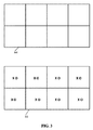
[0039] 図3は、4:4:4方式でサブサンプリングされた画像の一例を示す。4:4:4(および他のサブサンプリング方式)における数値の各々は、ソース画像上で行われたサブサンプリングの量を示す。サブサンプリングは、更に一般的には、J;a:bサブサンプリングとして表すこともでき、ここでJはサンプリングされる領域の行における画素数、および取り込まれるルミナンス・サンプル(YUV色空間におけるY)の数を示し、aはJ個の画素の最初の行において取り込まれるクロミナンス・サンプルの数(YUV色空間におけるUおよびV)を示し、bは、数値aに加えて、J個の画素の第2行において取り込まれるクロミナンス・サンプルの数を示す(b個のクロミナンス・サンプルも、YUV色空間におけるUおよびVであってよい)。 FIG. 3 shows an example of an image subsampled by the 4: 4: 4 method. Each of the numbers in 4: 4: 4 (and other subsampling schemes) indicates the amount of subsampling performed on the source image. Subsampling can also be expressed more generally as J; a: b subsampling, where J is the number of pixels in the row of the region being sampled, and the luminance sample that is captured (Y in the YUV color space). A represents the number of chrominance samples (U and V in the YUV color space) taken in the first row of J pixels, and b is the number of J pixels in addition to the numerical value a. Indicates the number of chrominance samples taken in two rows (b chrominance samples may also be U and V in YUV color space).
[0040] 画像300は、サブサンプル画像302が生成される元となる画像の一例である。画像300は、幅/行が4画素、高さ/列が2画素である。画素数は、画像300とサンプル画像302との間で同じままになっている。即ち、幅が4画素、高さが2画素である。画像300の各画素は、画像302におけるルミナンスに対して別個にサンプリングされており、画素に「x」の印を付けたのは、その画素がルミナンスに対してサンプリングされたことを意味する。加えて、画像300の各画素は、画像302におけるクロミナンスに対しても別個にサンプリングされており、画素に「o」の印を付けたのは、その画素がクロミナンスに対してサンプリングされたことを意味する。
The
[0041] サンプル画像302は、画像300の4:4:4サンプルを表す。何故ならJ、a、およびbは各々4に等しいからである。Jが4であるのは、問題のサンプリングされたエリアの幅が4画素であるからである。aが4であるのは、最上位行がクロミナンスに対して4回別個に、即ち、画素毎に1回サンプリングされたからである。bも4であるのは、最下位行がクロミナンスに対して更に4回別個にサンプリングされたからである(最上位行から取り込まれた4つのクロミナンス・サンプルに関して別個に追加の4回)。
[0041]
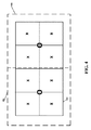
[0042] 図4は、4:2:0フォーマットでサンプリングされた図3の画像300の一例を示す。4:2:0サブサンプリングは、図300から取り込まれるクロミナンス・サンプルの方が少ないので、図3の画像302において示された4:4:4サブサンプリングとは異なる。ここでは、4:2:0サブサンプリング画像402において示すように、全部で8つの画素に対して2つのクロミナンス・サンプルだけが取り込まれる。4:2:0サブサンプリング方式では、aは2であるので、最上位行から2つのクロミナンス・サンプルが取り込まれる。加えて、bは0であるので、最下位行から取り込まれる追加のクロミナンス・サンプルはない。即ち、左側の4つ一組の画素404に対して1つのクロミナンス・サンプルが取り込まれ、そして右側の4つ一組の画素406に対して1つのクロミナンス・サンプルが取り込まれる。4:4:4サブサンプル画像302と4:2:0サブサンプル画像402との間の比較から分かるように、4:2:0サブサンプリング方式は、一般に、データー量を少なくして画像を格納することができるが、付随してその分忠実性が失われる。4:4:4サブサンプル画像302は、16個のサンプル、即ち、ルミナンスに8つ、クロミナンスに8つのサンプルを含む。4:2:0サブサンプル画像402は、10個のサンプル、即ち、ルミナンスに8つ、クロミナンスに2つのサンプルを含む。
FIG. 4 shows an example of the
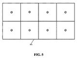
[0043] 図5は、4:0:0方式でサブサンプリングされた図3の画像300の一例を示す。図示のように、4:0:0サンプル画像502における8つの画素の各々は、ルミナンスに対してサンプリングされるが、これらのサンプルはいずれもクロミナンスに対してはサンプリングされない。4:0:0は、通常、白黒であると考えてよい。何故なら、ルミナンスはサンプリングするが、クロミナンスをサンプリングしないからである。4:0:0は、通常、ルミナンス値のみをサブサンプリングするために通例使用されることからグレースケールであると考えてもよいが、本発明の実施形態では一部のクロミナンス値のみをサンプリングするために使用することもできる。即ち、添付図面に関して説明するが、クロミナンス・データー(即ち、Yの代わりにUまたはV)は4:0:0方式でサンプリングすることができるので、そのクロミナンス・データーはサンプリングされるが、他方のクロミナンス・データー(即ち、UまたはVの他方)もルミナンス・データーもサンプリングされない。
FIG. 5 shows an example of the
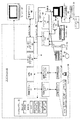
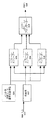
[0044] 図6は、本発明の実施形態を実現するエンコーダーのアーキテクチャーの一例を示す。図6のエンコーダー・アーキテクチャーは、例えば、図2のサーバー204において実現することができる。サーバー204は、図2のクライアント201とのリモート・プレゼンテーション・セッションを実行し、図7に示すデコーダーのアーキテクチャー例を実現することもできる。本発明の実施における種々の時点において、図6のアーキテクチャー例は、図3の画像300のような画像を取り込み、この画像から図3の4;4:4サンプル画像302、図4の4:2:0サンプル画像402、および/または図5の4:0:0サンプル画像を生成することができる。
FIG. 6 shows an example of an encoder architecture that implements an embodiment of the present invention. The encoder architecture of FIG. 6 can be implemented, for example, in the server 204 of FIG. The server 204 can also execute a remote presentation session with the client 201 of FIG. 2 to implement the example decoder architecture shown in FIG. At various points in the implementation of the present invention, the example architecture of FIG. 6 captures an image, such as
[0045] 最初に、データーのフレームがRGBフォーマットで取り込まれ、エンコーダーに対する入力600として用いられる。このデーターのフレームは、例えば、図2のGDI246がその出力を図2のリモート・ディスプレイ・サブシステム254に渡すに連れて取り込むことができ、この場合、図6のアーキテクチャーはリモート・ディスプレイ・サブシステム254において実現される。
[0045] Initially, a frame of data is captured in RGB format and used as
[0046] 色変換コンポーネント602は、入力フレーム600を取り込み、それをRGB色空間からYUV色空間(Y’UV、YCbCr、またはYPbPrと呼ばれることもある)に変換し、これから3つの成分フレーム、即ち、Y成分フレーム、U成分フレーム、およびV成分フレームを形成する。これら3つの成分フレームは、次に、1つまたは複数のエンコーダー・プロセスによって別個にエンコードされる。Y、U、およびV値は、これらとRGB値との間にある以下の関係を用いて決定することができる。
[0046] The
Y=0.299×R+0.114×G+0.587×B
U=0.436(B−Y/0.886)
V=0.615(R−Y/0.701)
[0047] 実施形態では、色変換コンポーネント602は入力フレーム600をRGB色空間からYUV色空間に変換する。次いで、色変換コンポーネント602は、YUVフレームを3つの別々の成分フレーム、即ち、Y、U、およびV成分毎に1つずつのフレームに平面化する(planarize)。これは、YUVフレームをビット・マスクで処理することによってというようにして、行うことができる。例えば、YUVフレームの各々が24ビット(Y、U、およびV値毎に8ビットずつ)を用いて表現される場合、Y成分フレームは、0xFF0000のビット・マスクを用いて各画素の論理ANDを取ることによって決定することができる(そして、UおよびVフレームは、それぞれ、0x00FF00および0x0000FFのビット・マスクを用いて論理ANDを取る)。本発明の実施形態では、1つの画素は、32ビットというような、24とは異なるビット数で表現することもでき、この場合、アルファ値は8ビットを用いて表現される。
Y = 0.299 × R + 0.114 × G + 0.587 × B
U = 0.436 (BY / 0.886)
V = 0.615 (R−Y / 0.701)
[0047] In an embodiment, the
[0048] 実施形態では、UおよびV値がそれらそれぞれの成分フレーム内において格納されている位置を変更して、それらの値が各画素の値の先頭に格納されるようにすることができる。即ち、UおよびV成分フレームの各画素を、それぞれ、8ビットおよび16ビットだけ論理的にビット単位で(bitwise)左にシフトすればよい(以上からの24ビット値の例を用いる)。例えば、値0xFF0000の画素を含むU成分フレームをビット単位で左に8ビット・シフトして、値0xFF0000の画素を生成することができる。この値の内左側8ビットを破棄し、この値の内右側16ビットを8ビットだけ左にシフトし、この値に8つのゼロを添付する。 [0048] In an embodiment, the position where the U and V values are stored in their respective component frames can be changed so that these values are stored at the beginning of the value of each pixel. That is, each pixel of the U and V component frames may be logically shifted to the left by 8 bits and 16 bits respectively (bitwise) (using the example of the 24-bit value from the above). For example, a U component frame including a pixel having a value of 0xFF0000 can be shifted to the left by 8 bits to generate a pixel having a value of 0xFF0000. Discard the left 8 bits of this value, shift the right 16 bits of this value to the left by 8 bits, and append 8 zeros to this value.
[0049] 本発明の実施形態は、UおよびV成分フレームに対してビット単位のシフトを実行するとよい。何故なら、エンコーダー608および610は4:0:0サブサンプリングを実行するように構成されるからである。この場合、ルミナンス値が通常位置するビットだけがサブサンプリングされる。UおよびV値が各画素値の最も左側に格納されるようにUおよびV成分フレームをビット単位でシフトすることにより、そして4:0:0サブサンプリングを実行するように構成されたエンコーダーを、これらのUおよびV成分フレームをサブサンプリングするために使用することができ、UおよびV値は通例画素の値の最も左側のビットには格納されない。
[0049] Embodiments of the present invention may perform bitwise shifts on U and V component frames. This is because
[0050] 本発明の実施形態は、必ずしも入力フレーム600をRGB色空間からYUV色空間に変換しなくてもよいが、更に一般的には、第1色空間から第2色空間に変換しなくてもよい。更に、本発明の実施形態では、フレームを第1色空間から第2色空間に全く変換しなくてもよい。入力フレームが同じ色空間において生成され、この同じ色空間においてフレーム・エンコーダー606〜610によってエンコードされる本発明の実施形態では、入力フレーム600が第1色空間から第2色空間に変換されないということでもよい。
[0050] The embodiment of the present invention does not necessarily convert the
[0051] 色変換コンポーネント602によって生成されたY、U、およびV成分フレームは、それぞれ、フレーム・エンコーダー606〜610に送られる。このエンコーディング・コンポーネントを、本明細書では、Yフレーム・エンコーダー606、Uフレーム・エンコーダー608、およびVフレーム・エンコーダー610と図示する。この図示は、論理的な図示であり、本発明の実施形態では、エンコーダー606、608、および610は、別個のエンコーダー・プロセスまたはコンポーネントであっても、またはなくてもよい。例えば、図6のエンコーダーがマルチプロセッサーまたはマルチコア・コンピューター・システム上のプロセスとして実現される場合、エンコーダー606、608、および610は別個のエンコーダー・プロセスであるとよい。図6のエンコーダーが単一プロセッサーまたは単一コア・コンピューター・システム上に実現される場合、あるいは1つのプロセッサーまたはコアだけにアクセスする場合、エンコーダー606、608、および610は、Y、U、およびVフレームを直列に処理する1つのエンコーダー・プロセスであるとよい。
[0051] The Y, U, and V component frames generated by the
[0052] 色変換コンポーネント602からのY、U、およびV成分フレームに加えて、エンコーダー606、608、および610は入力604も入力として取り込むことができる。これは、イントラ予測エンコーディングおよび/または量子化のためのモードを意味する。入力604は、4×4画素ルミネセンス・ブロックのイントラ予測モード、または16×16画素ルミネッセンス・ブロックのイントラ予測モードを意味することができる。実施形態では、4×4画素ブロックに対する予測は、入力604によって、垂直、水平、左下への対角線、右下への対角線、垂直右、水平下、垂直左、水平上、またはDCとして示すことができる。実施形態では、16×16画素ブロックに対する予測は、入力604によって、垂直、水平、平面、またはDCとして示すことができる。
[0052] In addition to the Y, U, and V component frames from
[0053] 量子化では、ある値の1つ以上の下位側ビットを破棄して、値を格納することができる空間の量を削減することができる。実施形態では、量子化は、指定されたビット数だけ値を論理的に右にシフトすることによって実現することができる。本発明の実施形態では、入力604は、実行する量子化の量を示すことができ、クライアントに送られるビット・ストリーム614の目標ビット・レートに基づくことができる。実施形態では、UおよびV値は、Y値よりも多い量だけ量子化するとよい。これは、通常人間はルミナンス情報よりもクロミナンス情報の欠如を認知し難いので、クロミナンス・データーの方がルミナス・データーよりも容易に廃棄でき、画像に対する忠実度を知覚可能な程に失うことがないからである。
[0053] In quantization, one or more lower-order bits of a value can be discarded to reduce the amount of space in which the value can be stored. In embodiments, quantization can be achieved by shifting the value logically to the right by a specified number of bits. In an embodiment of the present invention,
[0054] Yフレーム・エンコーダー606は、Y成分フレームをエンコードしたバージョンを4:0:0フォーマットで出力する。Y成分フレームは、図3の画像300を取り込み、これから図5のサブサンプリングされた4:0:0画像502を生成することができる。Yフレーム・エンコーダー606は、最初に、Y成分フレームを4:0:0方式でサンプリングし、次いでH.264ビデオのI−フレームのように、それをエンコードすることができる。I−フレームとは、以前のフレームや以後のフレームからの情報を用いることなくビデオの1フレームを表すフレームのことである。対照的に、P−フレームは以前のフレームからのデーターを参照し、B−フレームは以前のフレームおよび/または以後のフレームからのデーターを参照する。
The
[0055] Yフレーム・エンコーダー606によって実行される動作と同様、Uフレーム・エンコーダー608は、U成分フレームをエンコードしたバージョンを4:0:0フォーマットで出力し、Vフレーム・エンコーダー610は、V成分フレームをエンコードしたバージョンを4:0:0フォーマットで出力する。エンコーダー606、608、および610の各々は、それらのエンコードしたフレームをビット・ストリーム・アグリゲーター612に送る。
[0055] Similar to the operations performed by
[0056] ビット・ストリーム・アグリゲーター612は、エンコードされたフレームをビット・ストリームとしてエンコードする。H.264ビデオがクライアントにストリーミングされている場合、このビット・ストリームは、H.264ビデオのストリームを構成することができる。ビット・ストリーム・アグリゲーター612は、一般に、エンコードされたフレームを取り込み、これらをデーター・ストリームに組み立てることができる。データー・ストリームは、他のコンピューターにコンピューター・ネットワークを通じて、当該他のコンピューターによる表示のためにストリーミングされる。 [0056] The bit stream aggregator 612 encodes the encoded frame as a bit stream. H. If H.264 video is streamed to the client, this bit stream is H.264. A stream of H.264 video can be constructed. Bit stream aggregator 612 can generally capture encoded frames and assemble them into a data stream. The data stream is streamed to another computer over a computer network for display by the other computer.
[0057] ビット・ストリーム・アグリゲーター612は、更に、ビット・ストリームをクライアントに送る前に、これをカプセル化することができる。図示のように、フレームは既にエンコーダー608〜610によって圧縮されている場合もあり、更にビット・ストリーム・アグリゲーター612によって圧縮されてもよい。これは、レンペル−ジブ(Lempel-Ziv)圧縮(例えば、LZ77圧縮)のような、バルク圧縮技法を含むことができる。エンコードされた成分フレームを集計した後、ビット・ストリーム・アグリゲーター612は、エンコードされたビット・ストリーム614をRDPコンポーネント(図示せず)に送り、RDPコンポーネントは、次いで、このビット・ストリームをデコーディングおよび表示のためにクライアント(図2のクライアント201のような)に送信することができる。
[0057] The bit stream aggregator 612 may further encapsulate the bit stream before sending it to the client. As shown, the frame may already have been compressed by encoders 608-610 and may further be compressed by bit stream aggregator 612. This can include bulk compression techniques, such as Lempel-Ziv compression (eg, LZ77 compression). After summing the encoded component frames, the bit stream aggregator 612 sends the encoded
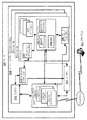
[0058] 図7は、本発明の実施形態を実現するデコーダーのアーキテクチャーの一例を示す。図7のデコーダー・アーキテクチャーは、例えば、図2のクライアント201において実現することができる。クライアント201は、図2のサーバー204とのリモート・プレゼンテーション・セッションを行う。サーバー204は、図6に示したエンコーダーのアーキテクチャーの一例を実現する。ネットワーク・データー700が、通信ネットワークを通じて受信される。実施形態では、ネットワーク・データーは、図6のエンコード・ビット・ストリーム614の表現となる。
[0058] FIG. 7 shows an example of the architecture of a decoder that implements an embodiment of the present invention. The decoder architecture of FIG. 7 can be realized, for example, in the client 201 of FIG. The client 201 performs a remote presentation session with the server 204 of FIG. The server 204 implements an example of the encoder architecture shown in FIG.
[0059] ネットワーク・データー700は、デコーダー702によってデコードされ、フレーム毎に3つの成分フレーム、即ち、Y成分フレーム、U成分フレーム、およびV成分フレームを生成する。ネットワーク・データー700がH.264ビデオとしてエンコードされリモート・プレゼンテーション・プロトコルによってカプセル化された場合、デコーダー702はネットワーク・データー700を分解し(un-encapsulate)デコードすることができる。デコーダー700は、ネットワーク・データー700をデコードして、1つのフレームのY、U、およびV成分フレームにすることができ、Y、U、およびV成分は4:0:0サブサンプリング方式になる。ネットワーク・データー702は、成分フレームのコピーではなく、成分フレームの表現にデコードしてもよく、この場合、ネットワーク・データーとして送られる前に、ある種の損失があるエンコーディングが成分フレームに対して実行される。例えば、成分フレームは、ネットワーク・データー700として送られる前に、量子化されてもよい。このように成分フレームが量子化されている場合、デコーダー702は成分フレームの複製ではなく、量子化された成分フレームの複製しか再生(recreate)することができなくてもよい。
[0059] The
[0060] 次に、デコーダー702によって生成された3つの成分フレームは、フレーム・アグリゲーター704に送られ、フレーム・アグリゲーター704はこれらの成分フレームを集計して、成分値の各々を含む1つのフレームにする。実施形態では、フレーム・アグリゲーター704は、最初にUおよびV成分フレームをそれぞれ8ビットおよび16ビット右にビット・シフトし、3つの成分フレームの論理ORを取ることによって、これらの成分フレームを組み合わせて1つのフレームにすることができる。
[0060] Next, the three component frames generated by the
[0061] 成分フレームにフレーム番号の指示が印される実施形態では(例えば、1つのフレームが3つの成分フレームに分割され、これらのフレームの各々に同じフレームの指示が印されるのでもよい)、フレーム・アグリゲーター704は、各成文フレームのフレーム番号の指示を判定し、同じ指示を共有する成分フレームを集計する。
[0061] In an embodiment where the frame number indication is marked on the component frame (eg, one frame may be divided into three component frames, and each of these frames may be marked with the same frame indication). The
[0062] 次いで、フレーム・アグリゲーター704は集計したフレームを色変換コンポーネント706に送る。色変換コンポーネントは、フレームを第1色空間から第2色空間に変換するように構成される。ここで、フレームがフレーム・アグリゲーター704からYUV色空間で受け取られ、RGB色空間でディスプレイ・デバイス上に表示される場合、色変換コンポーネント706はフレームをYUV色空間からRGB色空間に変換することができる。次いで、色変換コンポーネント706はRGB色空間のフレーム708をこのようなディスプレイ・デバイスに表示のために出力することができる。
Next, the
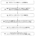
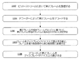
[0063] 図8は、本発明の実施形態を実現するエンコーダーの動作手順の一例を示す。実施形態では、図8の動作手順は、図2のリモート・プレゼンテーション・サーバー204において実現することができる。本発明の実施形態では、図8の動作手順全てが実施されるのではない場合もあり、および/または図8の動作手順は、図示したのとは異なる順序で実施される場合もある。これは、以下の図9〜図11の動作手順にも該当する。 FIG. 8 shows an example of the operation procedure of the encoder that realizes the embodiment of the present invention. In an embodiment, the operational procedure of FIG. 8 may be implemented in the remote presentation server 204 of FIG. In embodiments of the present invention, not all of the operational procedures of FIG. 8 may be performed and / or the operational procedures of FIG. 8 may be performed in a different order than illustrated. This also corresponds to the operation procedure shown in FIGS.
[0064] 動作802は、RGBフォーマットのフレームを受信することを示す。RGBフォーマットのフレームは、図6のRDP入力600が図6の色変換コンポーネント602によって受信されるのと同様に受信されればよい。
[0064] Operation 802 indicates receiving a frame in RGB format. The frame in the RGB format may be received in the same manner as the
[0065] 動作804は、フレームをY成分フレーム、U成分フレーム、およびV成分フレームに変換することによってというようにして、フレームをYUVに変換し、このフレームを平面化する(planarize)ことを示す。動作804は、図6の色変換コンポーネント602を実現するのと同様の方法で実現すればよい。実施形態では、動作804は、フレームが画面データーであると判断したことに応答して実行することができる。実施形態では、動作804は、このフレームの各成分フレームに共通指示(shared indication)を印して、これら3つの成分フレームが同じフレームに属するまたは同じフレームから生じたことが識別できるようにする。このような実施形態では、動作804は、エンコードされたY、U、およびY成分フレームの各々に、フレームに対する参照を印してもよい。
[0065] Operation 804 indicates converting the frame to YUV and planarizing the frame by converting the frame into a Y component frame, a U component frame, and a V component frame, and so on. . The operation 804 may be realized by the same method as that for realizing the
[0066] 動作806は、Y、U、およびV成分フレームの各々を4:0:0サブサンプリング・フォーマットでエンコードすることを示す。4:0:0サブサンプリング・フォーマットは、通常では、画像データーの画素の値をサブサンプリングすることを含むのでよい。動作806は、4:4:4サブサンプリング方式でフレームをエンコードするように構成されていない(各画素の各値が個々にサンプリングされる。例えば、各画素の各Y、U、およびV値が個々にサンプリングされる)が、4:2:0のように、各クロミナンス値を別個にサンプリングしないサブサンプリング方式でフレームをエンコードするように構成されたエンコーダーを用いて実行することができる。動作806は、図6のYフレーム・エンコーダー606、Uフレーム・エンコーダー608、およびVフレーム・エンコーダー610において実現することができる。実施形態では、動作806は、H.264イントラ・エンコーダーを用いて、4:0:0サブサンプリング方式でY、U、およびV成分フレームの各々のエンコードすることを含む。
[0066]
[0067] 実施形態では、動作806のエンコーディングは、一種のインフラ予測(infra prediction)に基づいて実行される。このような実施形態では、動作806は、Y、U、およびV成分フレームの各々をエンコードするために用いられるイントラ予測のレベルを決定することを含むとよく、このイントラ予測のレベルに基づいて、Y、U、およびV成分フレームの各々をエンコーダーによってイントラ予測エンコーディングすることを含む。このようなイントラ予測エンコーディングは、図8の動作手順を実現するコンピューターに利用可能な利用可能計算リソースの量を判定することに基づいて実行されるとよい。
[0067] In an embodiment, the encoding of
[0068] 実施形態では、動作806のエンコーディングは、量子化を実行することを含む。このような実施形態では、動作806は、エンコードされたY、U、およびV成分フレームをリモート・プレゼンテーション・セッション・プロトコル・ビット・ストリームにエンコードする前に、エンコードされたY、U、およびV成分フレームを量子化する量子化量を決定し、エンコードされたY、U、およびV成分を量子化することを含むとよい。実施形態では、エンコードされたY、U、およびV成分フレームを量子化する量子化量を決定する動作は、Y成分フレームを量子化する第1量子化量と、UおよびV成分フレームを量子化する第2量子化量とを決定する動作を含み、第1量子化量は第2量子化量よりも少ない量子化となる。実施形態では、エンコードされたY、U、およびV成分フレームを量子化する量子化量を決定するには、ビット・ストリームの目標ビット・レートに基づく。
[0068] In an embodiment, the encoding of
[0069] 動作808は、エンコードされたY、U、およびV成分フレームを、リモート・プレゼンテーション・セッション・プロトコル・ビット・ストリームにエンコードすることを示す。動作808は、図6のビット・ストリーム・アグリゲーター612において実現することができる。
[0069]
[0070] 動作810は、ビット・ストリームをコンピューターにリモート・プレゼンテーション・セッションを通じて送ることを示し、このコンピューターはビット・ストリームをデコードして、Y、U、およびV成分フレームの各々の4:0:0フォーマットとした表現を生成し、Y、U、およびV成分フレームの各々の表現を組み合わせて、4:4:4フォーマットのYUVフレームとし、このYUVフレームをコンピューターがディスプレイ・デバイス上に表示する。ビット・ストリームが送られる先のコンピューターは、図2のクライアント201とすることができる。
[0070]
[0071] 図9は、本発明の実施形態を実現するエンコーダーの動作手順の追加例を示す。図9の動作手順は、図2のサーバー204のような、図8の動作手順を実現する同じコンピューター上に実現することができる。図8は、グラフィック・データーをエンコードしてクライアント・コンピューターにビデオとして送り、クライアントが受信したビデオのフレームを4:4:4方式で再生することができる動作手順を示し、図9は、4:2:0方式のビデオのように、必要なサブサンプリングが少なくて済む方式で、グラフィック・データーをエンコードしてクライアント・コンピューターにビデオとして送るときの動作手順を示す。図8および図9の動作手順は双方共、同じコンピューター上において実現することができ、1つのリモート・プレゼンテーション・セッションにおいて、生成される異なるタイプのグラフィック・データーをエンコードするために用いることができる。即ち、コンピューターがあるタイプのデーター(画面データー、即ち、コンピューター・デスクトップのグラフィック出力のようなデーターであり、テキストが存在する場合もある)をエンコードしている場合、コンピューターは図8の動作手順を用いればよく、コンピューターが他のタイプのデーター(ビデオのようなデーター)をエンコードしているとき、コンピューターは図9の動作手順を用いればよい。 FIG. 9 shows an additional example of the operation procedure of the encoder that realizes the embodiment of the present invention. The operating procedure of FIG. 9 can be implemented on the same computer that implements the operating procedure of FIG. 8, such as the server 204 of FIG. FIG. 8 shows an operation procedure in which the graphic data is encoded and sent to the client computer as a video, and the video frame received by the client can be played back in the 4: 4: 4 format. An operation procedure for encoding graphic data and sending it to a client computer as a video in a format that requires less subsampling, such as a 2: 0 format video, is shown. Both the operating procedures of FIGS. 8 and 9 can be implemented on the same computer and can be used to encode different types of graphic data generated in a single remote presentation session. That is, if the computer is encoding some type of data (screen data, ie, data such as computer desktop graphic output, text may be present), the computer performs the operational procedure of FIG. The computer may use the operating procedure of FIG. 9 when the computer is encoding other types of data (data such as video).
[0072] 動作902は、RGBフォーマットの第2フレームを受信することを示す。実施形態では、動作902は、図6の色変換コンポーネント602がRGB入力600を受信するのと同様に実行する(effectuate)ことができる。
[0072] Act 902 indicates receiving a second frame in RGB format. In an embodiment, operation 902 can be effected in the same manner as
[0073] 動作904は、第2フレームがビデオ・データーであることに基づいて、第2フレームを平面化しないと決定することを示す。実施形態では、動作904は、第2フレームがビデオ・データーであることに基づいて、このフレームを第2Y成分フレーム、第2U成分フレーム、および第2V成分フレームに変換しないと決定することを含むのでよい。尚、フレームが成分フレームに平面化され次いでエンコードされる場合(4:4:4サブサンプリング方式のフレームをクライアントによって受信できるように)、このフレームはテキストを含む可能性が高い画面データーであるので、他のタイプのデーターよりも、それと共に伝えられる忠実度は一層重要になると言える。ここでは、第2フレームはビデオ・データーであると判定され、したがって、その結果、このフレームはその成分フレームに変換されなくてもよい。 [0073] Act 904 indicates deciding not to planarize the second frame based on the second frame being video data. In an embodiment, operation 904 includes determining not to convert this frame into a second Y component frame, a second U component frame, and a second V component frame based on the second frame being video data. Good. Note that if the frame is flattened into component frames and then encoded (so that a 4: 4: 4 subsampling frame can be received by the client), this frame is screen data that is likely to contain text. The fidelity conveyed with it is more important than other types of data. Here, the second frame is determined to be video data, and as a result, this frame may not be converted to its component frame.
[0074] 動作906は、第2フレームをYUVフォーマットに変換することを示す。実施形態では、動作906は図6の色変換コンポーネント602において実現することができるが、このような場合、色変換コンポーネント602は第2フレームを成分フレームに平面化しないでよい。
[0074] Act 906 indicates converting the second frame to YUV format. In an embodiment, operation 906 may be implemented in
[0075] 動作908は、変換された第2フレームをエンコーダーによってエンコードすることを示す。実施形態では、第2フレームは、4:2:2または4:2:0サブサンプリング方式のような、4:4:4サブサンプリング方式未満のいずれかで、エンコーダーによってエンコードされればよい。しかしながら、4:0:0サブサンプリング方式で成分フレームをエンコードするために図8において使用した同じエンコーダー(そして、これらの成分フレームを後に4:4:4サブサンプリング方式のフレームの表現として組み立て直すこともできる)を、動作908においても使用して、第2フレームを4:2:0サブサンプリング方式でエンコードすることもできる。本発明の実施形態では、第2フレームをエンコードする動作は、第2フレームをH.264ビデオのフレームにエンコードする動作を含むとよい。
[0075]
[0076] 動作910は、エンコードされた第2フレームをリモート・プレゼンテーション・セッション・プロトコル・ビット・ストリームにエンコードすることを示す。動作910は、図8の動作808が実現されたのと同じように実行することができる。
[0076] Act 910 indicates encoding the encoded second frame into a remote presentation session protocol bit stream. Operation 910 may be performed in the same manner as
[0077] 動作912は、ビット・ストリームをコンピューターに、リモート・プレゼンテーション・セッションを通じて送ることを示す。次いで、コンピューターは、ビット・ストリームに基づいて、第2フレームの表現をディスプレイ・デバイス上に表示することができる。動作912は、図8の動作810が実現されたのと同じように実行することができる。
[0077]
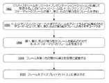
[0078] 図10は、本発明の実施形態を実現するデコーダーの動作手順の一例を示す。実施形態では、図10の動作手順は、図7のデコーダーを実現するために用いることができ、更に図6のエンコーダーによって生成されたビット・ストリームをデコードするために用いることもできる。 FIG. 10 shows an example of an operation procedure of the decoder that realizes the embodiment of the present invention. In an embodiment, the operational procedure of FIG. 10 can be used to implement the decoder of FIG. 7, and can also be used to decode the bit stream generated by the encoder of FIG.
[0079] 動作1002は、ビット・ストリームをリモート・プレゼンテーション・セッションを通じて受信することを示し、このビット・ストリームは、当該フレームの第1、第2、および第3成分フレームを含み、第1、第2、および第3成分フレームの各々は、4:0:0サブサンプリング・フォーマットになっている。これは、図8の動作810において生成されたビット・ストリームであってもよい。第1、第2、および第3成分フレームは、それぞれ、YUVフレームのY、U、およびV成分フレームであってもよい。リモート・プレゼンテーション・セッションを通じて受信されたビット・ストリームがリモート・プレゼンテーション・プロトコルによってカプセル化された実施形態では、動作1002はビット・ストリームを分解する(un-encapsulate)ことを含むとよい。
[0079]
[0080] 動作1004は、デコーダーによってというように、第1、第2、および第3成分フレームの各々をデコードすることを示す。実施形態では、動作1002は図7のデコーダー702において実現することができる。実施形態では、デコーダーは、4:4:4サブサンプリング方式でフレームをデコードするように構成されるのではなく、デコーダーは4:2:0サブサンプリング方式でエンコードするように構成される。
[0080]
[0081] 動作1006は、第1、第2、および第3成分フレームを組み合わせて4:4:4フォーマットのフレームを生成することを示す。実施形態では、動作1006は図7のフレーム・アグリゲーター704において実現することができる。実施形態では、動作1006は、論理OR演算によって、第1、第2、および第3成分フレームを組み合わせることを含むとよい。実施形態では、動作1006は、各々第2フレームの識別子を有する、第1、第2、および第3成分フレームに基づいて、第1、第2、および第3成分フレームを組み合わせることを決定することを含む。
[0081]
[0082] 動作1008は、フレームを第1色空間から第2色空間に変換することを示す。実施形態では、動作1008は図7の色変換コンポーネント706において実現することができる。実施形態では、動作1008は、フレームをディスプレイ・デバイス上に表示する前に、フレームをYUV色空間からRGB色空間に変換することを含むのでもよい。
[0082] Act 1008 indicates converting the frame from the first color space to the second color space. In an embodiment, operation 1008 may be implemented in
[0083] 動作1010は、フレームをディスプレイ・デバイス上に表示することを示す。図10の動作図が図1のコンピューター20において実現される場合、ディスプレイ・デバイス上にフレームを表示する動作は、図1のディスプレイ47上にフレームを表示することを含むとよい。 [0083] Act 1010 indicates displaying the frame on a display device. When the operation diagram of FIG. 10 is implemented in the computer 20 of FIG. 1, the operation of displaying the frame on the display device may include displaying the frame on the display 47 of FIG.
[0084] 図11は、本発明の実施形態を実現するエンコーダーの動作手順の追加例を示す。図11の動作手順は、図2のクライアント201のような、図10の動作手順を実現する同じコンピューター上に実現することができる。図10は、図8の動作手順を実現することによって生成される成分フレームのような、成分フレームをデコードし集計するために用いることができる動作手順を示す。対照的に、図11は、図9の動作手順を実現することによって生成される成分フレームのように、成分フレームとしてエンコードも送信もされなかったフレームをデコードするために用いることができる。 FIG. 11 shows an additional example of the operation procedure of the encoder that realizes the embodiment of the present invention. The operation procedure of FIG. 11 can be implemented on the same computer that implements the operation procedure of FIG. 10, such as the client 201 of FIG. 2. FIG. 10 illustrates an operational procedure that can be used to decode and aggregate component frames, such as the component frames generated by implementing the operational procedure of FIG. In contrast, FIG. 11 can be used to decode a frame that was not encoded or transmitted as a component frame, such as a component frame generated by implementing the operational procedure of FIG.
[0085] 動作1102は、ビット・ストリームにおいて第2フレームを受信することを示す。実施形態では、第2フレームは4:0:0サブサンプリング方式ではなく、4:2:0サブサンプリング方式になっている。動作1102は、図10の動作1002が実現されるのと同じように実現することができる。
[0085] Act 1102 indicates receiving a second frame in the bit stream. In the embodiment, the second frame is not a 4: 0: 0 subsampling method but a 4: 2: 0 subsampling method. Operation 1102 can be implemented in the same way that
[0086] 動作1004は、デコーダーによって第2フレームをデコードすることを示す。図8では、デコーダーは、4:0:0サブサンプリング方式で3つの成分フレームをデコードするために用いられた。ここでも、第2フレームはこのデコーダーによってデコードするのでよいが、第2フレームは成分フレームとは異なるサブサンプリング方式、例えば、4:2:0サブサンプリング方式または4:2:2サブサンプリング方式となる。
[0086]
[0087] 動作1106は、第2フレームが成分フレームでないことに基づいて、第2フレームを他のフレームと組み合わせないと決定することを示す。図10におけるように、成分フレームが受信された場合、これらを集計してその元のフレームの表現を生成することができる。第2フレームは成分フレームではない。これは、1つのフレーム内にその成分の全てを含む。第2フレームは成分フレームではないので、本発明の実施形態では、これは他のいずれのフレームとも集計されない。第2フレームが成分フレームではないと判定する動作は、例えば、第2フレームが4:0:0サブサンプリング方式ではないと判定することによって実行するとよい。フレームにフレーム指示または参照が付帯されるまたは印される実施形態では、第2フレームが成分フレームでないと判定する動作は、第2フレームには、それが成分フレームでないことを示す参照が付帯されているまたは印されていることを判定することによって実行するのでもよい。 [0087] Act 1106 indicates deciding not to combine the second frame with other frames based on the second frame not being a component frame. As in FIG. 10, when component frames are received, they can be aggregated to generate a representation of the original frame. The second frame is not a component frame. This includes all of its components in one frame. Since the second frame is not a component frame, in an embodiment of the present invention it is not aggregated with any other frame. The operation of determining that the second frame is not a component frame may be executed by determining that the second frame is not a 4: 0: 0 subsampling method, for example. In embodiments where a frame designation or reference is attached or marked to the frame, the act of determining that the second frame is not a component frame is accompanied by a reference indicating that it is not a component frame. It may be performed by determining that it is or is marked.
[0088] 動作1108は、デコードされた第2フレームをディスプレイ・デバイス上に表示することを示す。動作1108は、図10の動作1010が実現されるのと同様に実現することができる。
[0088]
[0089] 以上、種々の図に示される好ましい態様と関連付けて本発明について説明したが、他の同様の態様を使用してもよく、本開示から逸脱することなく、本開示の同じ機能を実行するために、説明した態様に対して変更や追加が行われてもよいことは言うまでもない。したがって、本開示は、いずれの1つの態様にも限定されず、逆に、添付する特許請求の範囲にしたがってその広さおよび範囲が解釈されてしかるべきである。例えば、本明細書において説明した種々の手順は、ハードウェアまたはソフトウェア、あるいは双方の組み合わせで実現することができる。本発明は、コンピューター読み取り可能記憶媒体および/またはコンピューター読み取り可能通信媒体で実現することもできる。つまり、本発明、あるいはそのある種の態様または部分は、フロッピー・ディスケット、CD−ROM、ハード・ドライブ、または他のあらゆる機械読み取り可能記憶媒体のような、有形媒体に具体化されたプログラム・コード(即ち、命令)の形態をなすことができる。同様に、本発明、あるいはそのある種の態様または部分は、伝搬信号、または他のあらゆる機械読み取り可能通信媒体において実現することもできる。プログラム・コードが、コンピューターのような機械にロードされこの機械によって実行されると、この機械が、開示した実施形態を実施するように構成された装置となる。本明細書において明示的に明記した具体的な実施態様に加えて、他の態様および実施態様も、ここに開示した明細書を検討することによって、当業者には明白であろう。尚、本明細書および図示した実施態様は、例示としてのみ考慮されることを意図している。 [0089] While the invention has been described in connection with the preferred embodiments shown in the various figures, other similar embodiments may be used and perform the same functions of the disclosure without departing from the disclosure. Needless to say, modifications and additions may be made to the described aspects. Accordingly, the present disclosure is not limited to any one aspect, but on the contrary, its breadth and scope should be construed in accordance with the appended claims. For example, the various procedures described herein can be implemented in hardware or software, or a combination of both. The present invention can also be realized in computer readable storage media and / or computer readable communication media. That is, the present invention, or certain aspects or portions thereof, is embodied in program code embodied in a tangible medium, such as a floppy diskette, CD-ROM, hard drive, or any other machine-readable storage medium. (That is, an instruction). Similarly, the invention, or certain aspects or portions thereof, may be implemented in a propagated signal or any other machine-readable communication medium. When the program code is loaded into and executed by a machine such as a computer, the machine becomes a device configured to implement the disclosed embodiments. In addition to the specific embodiments explicitly specified herein, other aspects and embodiments will be apparent to those skilled in the art from consideration of the specification disclosed herein. The specification and illustrated embodiments are intended to be considered as exemplary only.
Claims (10)
RGBフォーマットのフレームを、Y成分フレームと、U成分フレームと、V成分フレームとに変換するステップと、
前記Y、U、およびV成分フレームの各々を、前記第2サブサンプリング方式で前記エンコーダーによってエンコードするステップと、
前記エンコードされたY、U、およびV成分フレームをリモート・プレゼンテーション・セッション・プロトコル・ビット・ストリームにエンコードするステップと、
前記ビット・ストリームをコンピューターに、リモート・プレゼンテーション・セッションを通じて送るステップであって、前記コンピューターが、前記ビット・ストリームをデコードして、前記第2サブサンプリング方式の前記Y、U、およびV成分フレームの各々の表現を生成し、前記Y、U、およびV成分フレームの各々の前記表現を組み合わせて、前記コンピューターがディスプレイ・デバイス上に表示する、前記第1サンプリング方式のYUVフレームを得る、ステップと、
を含む、方法。 A method of encoding a remote presentation session using a first sub-sampling method, wherein the operation of sampling data using the first sub-sampling method is configured to encode a frame using a second sub-sampling method. Including an operation of individually sampling each pixel of image data by an encoder not configured to encode a frame by the first sampling method, and the operation of sampling the data by the second sub-sampling method includes: Including sub-sampling pixel values;
Converting a frame in RGB format into a Y component frame, a U component frame, and a V component frame;
Encoding each of the Y, U, and V component frames with the encoder in the second sub-sampling scheme;
Encoding the encoded Y, U, and V component frames into a remote presentation session protocol bit stream;
Sending the bit stream to a computer through a remote presentation session, wherein the computer decodes the bit stream and includes the Y, U, and V component frames of the second sub-sampling scheme. Generating each representation and combining the representation of each of the Y, U, and V component frames to obtain a YUV frame of the first sampling scheme that the computer displays on a display device;
Including a method.
H.264イントラ・エンコーダーによって、4:0:0サブサンプリング方式で前記Y、U、およびV成分フレームの各々をエンコードするステップを含む、方法。 The method of claim 1, wherein encoding each of the Y, U, and V component frames of the second subsampling scheme with the encoder comprises:
H. Encoding each of the Y, U, and V component frames in a 4: 0: 0 subsampling manner with a H.264 intra encoder.
前記Y、U、およびV成分フレームの各々をエンコードするためのイントラ予測のレベルを決定するステップと、前記イントラ予測のレベルに基づいて、前記エンコーダーによって、前記Y、U、およびV成分フレームの各々をイントラ予測エンコードするステップと、
を含む、方法。 The method of claim 1, wherein encoding each of the Y, U, and V component frames of the second subsampling scheme with the encoder comprises:
Determining an intra prediction level for encoding each of the Y, U, and V component frames; and, based on the intra prediction level, each of the Y, U, and V component frames by the encoder. Encoding for intra prediction,
Including a method.
利用可能な計算リソースの量に基づいて、前記イントラ予測のレベルを決定するステップを含む、方法。 4. The method of claim 3, wherein determining the level of intra prediction comprises:
Determining the level of intra prediction based on an amount of available computational resources.
前記エンコードされたY、U、およびV成分フレームを量子化するために、量子化量を決定するステップと、
前記エンコードされたY、U、およびV成分フレームを前記リモート・プレゼンテーション・セッション・プロトコル・ビット・ストリームにエンコードする前に、前記エンコードされたY、U、およびV成分フレームを量子化するステップと、
を含む、方法。 The method of claim 1, further comprising:
Determining a quantization amount to quantize the encoded Y, U, and V component frames;
Quantizing the encoded Y, U, and V component frames before encoding the encoded Y, U, and V component frames into the remote presentation session protocol bit stream;
Including a method.
前記Y成分フレームを量子化するための第1量子化量と、前記UおよびV成分フレームを量子化するための第2量子化量とを決定するステップを含み、前記第1量子化量が前記第2量子化量よりも少ない量子化である、方法。 6. The method of claim 5, wherein determining the amount of quantization to quantize the encoded Y, U, and V component frames comprises:
Determining a first quantization amount for quantizing the Y component frame and a second quantization amount for quantizing the U and V component frames, wherein the first quantization amount is A method, wherein the quantization is less than a second quantization amount.
前記ビット・ストリームの目標ビット・レートに基づいて、前記エンコードされたY、U、およびV成分フレームを量子化するための前記量子化量を決定するステップを含む、方法。 6. The method of claim 5, wherein determining the amount of quantization to quantize the encoded Y, U, and V component frames comprises:
Determining the amount of quantization for quantizing the encoded Y, U, and V component frames based on a target bit rate of the bit stream.
前記フレームが画面データーであると判定したことに基づいて、前記フレームを前記Y成分フレームと、前記U成分フレームと、前記V成分フレームとに変換するステップを含む、方法。 The method of claim 1, further comprising:
And converting the frame into the Y component frame, the U component frame, and the V component frame based on determining that the frame is screen data.
RGBフォーマットの第2フレームを受信するステップと、
前記第2フレームがビデオ・データーであることに基づいて、前記フレームを第2Y成分フレームと、第2U成分フレームと、第2V成分フレームとに変換しないと決定するステップと、
前記第2フレームをYUVフォーマットに変換するステップと、
前記変換された第2フレームを、前記エンコーダーによってエンコードするステップと、
前記エンコードされた第2フレームを、前記リモート・プレゼンテーション・セッション・プロトコル・ビット・ストリームにエンコードするステップと、
前記ビット・ストリームを前記コンピューターに、前記リモート・プレゼンテーション・セッションを通じて送るステップであって、前記コンピューターが、前記ビット・ストリームに基づいて、前記第2フレームの表現を前記ディスプレイ・デバイス上に表示するステップと、
を含む、方法。 9. The method of claim 8, further comprising:
Receiving a second frame in RGB format;
Determining not to convert the frame into a second Y component frame, a second U component frame, and a second V component frame based on the second frame being video data;
Converting the second frame to YUV format;
Encoding the transformed second frame by the encoder;
Encoding the encoded second frame into the remote presentation session protocol bit stream;
Sending the bit stream to the computer through the remote presentation session, the computer displaying a representation of the second frame on the display device based on the bit stream. When,
Including a method.
Applications Claiming Priority (2)
| Application Number | Priority Date | Filing Date | Title |
|---|---|---|---|
| US13/237,859 US9712847B2 (en) | 2011-09-20 | 2011-09-20 | Low-complexity remote presentation session encoder using subsampling in color conversion space |
| US13/237,859 | 2011-09-20 |
Publications (2)
| Publication Number | Publication Date |
|---|---|
| JP2014530563A true JP2014530563A (en) | 2014-11-17 |
| JP2014530563A5 JP2014530563A5 (en) | 2015-12-10 |
Family
ID=47858204
Family Applications (1)
| Application Number | Title | Priority Date | Filing Date |
|---|---|---|---|
| JP2014531861A Pending JP2014530563A (en) | 2011-09-20 | 2012-09-12 | Low complexity remote presentation session encoder |
Country Status (12)
| Country | Link |
|---|---|
| US (1) | US9712847B2 (en) |
| EP (1) | EP2759140B1 (en) |
| JP (1) | JP2014530563A (en) |
| KR (1) | KR101962990B1 (en) |
| CN (1) | CN102984512B (en) |
| AU (1) | AU2012312810B2 (en) |
| BR (1) | BR112014006576B1 (en) |
| CA (1) | CA2849091A1 (en) |
| HK (1) | HK1181227A1 (en) |
| MX (1) | MX2014003435A (en) |
| RU (1) | RU2603627C2 (en) |
| WO (1) | WO2013043420A1 (en) |
Families Citing this family (13)
| Publication number | Priority date | Publication date | Assignee | Title |
|---|---|---|---|---|
| WO2012013999A1 (en) * | 2010-07-29 | 2012-02-02 | B-K Medical Aps | Motion-compensated processing |
| US9769227B2 (en) | 2014-09-24 | 2017-09-19 | Microsoft Technology Licensing, Llc | Presentation of computing environment on multiple devices |
| US10448111B2 (en) | 2014-09-24 | 2019-10-15 | Microsoft Technology Licensing, Llc | Content projection |
| US10025684B2 (en) * | 2014-09-24 | 2018-07-17 | Microsoft Technology Licensing, Llc | Lending target device resources to host device computing environment |
| US10635296B2 (en) | 2014-09-24 | 2020-04-28 | Microsoft Technology Licensing, Llc | Partitioned application presentation across devices |
| US9691349B2 (en) | 2015-04-01 | 2017-06-27 | Apple Inc. | Source pixel component passthrough |
| US20170366819A1 (en) * | 2016-08-15 | 2017-12-21 | Mediatek Inc. | Method And Apparatus Of Single Channel Compression |
| CN106657960B (en) * | 2016-09-30 | 2018-12-25 | 北京集创北方科技股份有限公司 | Color space changover method |
| CN108259690A (en) * | 2016-12-28 | 2018-07-06 | 乐视汽车(北京)有限公司 | Image transfer method and device |
| US11638040B2 (en) | 2020-08-24 | 2023-04-25 | Schmied Enterprises LLC | Eco-friendly codec-based system for low latency transmission |
| CN114371811A (en) * | 2020-10-15 | 2022-04-19 | 伊姆西Ip控股有限责任公司 | Method, electronic device and computer program product for storage management |
| CN113365083B (en) * | 2021-07-08 | 2022-10-11 | 广州市保伦电子有限公司 | H.265-based YUV444 image coding and decoding method |
| US11838513B2 (en) * | 2022-01-14 | 2023-12-05 | Meta Platforms Technologies, Llc | Progressive transmission of detailed image data via video compression of successive subsampled frames |
Citations (5)
| Publication number | Priority date | Publication date | Assignee | Title |
|---|---|---|---|---|
| JP2004535126A (en) * | 2001-07-12 | 2004-11-18 | ドルビー・ラボラトリーズ・ライセンシング・コーポレーション | Method and system for improving compressed image chroma information |
| JP2005160048A (en) * | 2003-10-28 | 2005-06-16 | Matsushita Electric Ind Co Ltd | Intra-picture prediction coding method |
| WO2007034601A1 (en) * | 2005-09-20 | 2007-03-29 | Mitsubishi Electric Corporation | Image encoding method, image decoding method, image encoding apparatus, image decoding apparatus, image encoded bitstream and recording medium |
| WO2010004726A1 (en) * | 2008-07-08 | 2010-01-14 | パナソニック株式会社 | Image coding method, image decoding method, image coding device, image decoding device, program, and integrated circuit |
| JP2010068103A (en) * | 2008-09-09 | 2010-03-25 | Fujitsu Ltd | Encoding device and encoding program |
Family Cites Families (69)
| Publication number | Priority date | Publication date | Assignee | Title |
|---|---|---|---|---|
| US5384912A (en) * | 1987-10-30 | 1995-01-24 | New Microtime Inc. | Real time video image processing system |
| JPH07177502A (en) * | 1993-12-17 | 1995-07-14 | Sutajio Gen:Kk | Method for compressing picture information, compressed picture information recording medium, and compressed picture information reproducing device |
| JPH0983893A (en) * | 1995-09-08 | 1997-03-28 | Matsushita Electric Ind Co Ltd | Television receiver |
| JP2861890B2 (en) * | 1995-09-28 | 1999-02-24 | 日本電気株式会社 | Color image display |
| US5768429A (en) * | 1995-11-27 | 1998-06-16 | Sun Microsystems, Inc. | Apparatus and method for accelerating digital video decompression by performing operations in parallel |
| KR100186409B1 (en) * | 1996-04-23 | 1999-05-01 | 구자홍 | Circuit for processing pip image signal suitable type in the tv and pc |
| US5905536A (en) * | 1997-06-05 | 1999-05-18 | Focus Enhancements, Inc. | Video signal converter utilizing a subcarrier-based encoder |
| JP3448462B2 (en) * | 1997-06-25 | 2003-09-22 | 三洋電機株式会社 | Image data compression device |
| US6043845A (en) * | 1997-08-29 | 2000-03-28 | Logitech | Video capture and compression system and method for composite video |
| US6091777A (en) * | 1997-09-18 | 2000-07-18 | Cubic Video Technologies, Inc. | Continuously adaptive digital video compression system and method for a web streamer |
| JP4071328B2 (en) * | 1997-11-18 | 2008-04-02 | 富士通株式会社 | Document image processing apparatus and method |
| US6829301B1 (en) * | 1998-01-16 | 2004-12-07 | Sarnoff Corporation | Enhanced MPEG information distribution apparatus and method |
| US7103226B1 (en) * | 1998-03-23 | 2006-09-05 | Ati Technologies, Inc. | Video processor with composite graphics and video picture elements |
| US6661422B1 (en) * | 1998-11-09 | 2003-12-09 | Broadcom Corporation | Video and graphics system with MPEG specific data transfer commands |
| JP2000197050A (en) * | 1998-12-25 | 2000-07-14 | Canon Inc | Image processing unit and its method |
| US20020135683A1 (en) * | 1999-12-20 | 2002-09-26 | Hideo Tamama | Digital still camera system and method |
| US6707853B1 (en) * | 2000-01-10 | 2004-03-16 | Intel Corporation | Interface for performing motion compensation |
| US6961063B1 (en) * | 2000-06-30 | 2005-11-01 | Intel Corporation | Method and apparatus for improved memory management of video images |
| US20020090140A1 (en) * | 2000-08-04 | 2002-07-11 | Graham Thirsk | Method and apparatus for providing clinically adaptive compression of imaging data |
| US7576748B2 (en) * | 2000-11-28 | 2009-08-18 | Nintendo Co. Ltd. | Graphics system with embedded frame butter having reconfigurable pixel formats |
| JP3631169B2 (en) * | 2001-06-19 | 2005-03-23 | 三洋電機株式会社 | Digital camera |
| US6842484B2 (en) * | 2001-07-10 | 2005-01-11 | Motorola, Inc. | Method and apparatus for random forced intra-refresh in digital image and video coding |
| US7142251B2 (en) * | 2001-07-31 | 2006-11-28 | Micronas Usa, Inc. | Video input processor in multi-format video compression system |
| US6977659B2 (en) * | 2001-10-11 | 2005-12-20 | At & T Corp. | Texture replacement in video sequences and images |
| CA2380105A1 (en) * | 2002-04-09 | 2003-10-09 | Nicholas Routhier | Process and system for encoding and playback of stereoscopic video sequences |
| KR100930043B1 (en) * | 2002-11-23 | 2009-12-08 | 삼성전자주식회사 | Motion estimating apparatus and method for detecting scrolling text or graphic data |
| US7184094B2 (en) * | 2002-12-06 | 2007-02-27 | Motorola, Inc. | Decoding system, video color converter and method thereof |
| JP4270892B2 (en) * | 2003-01-27 | 2009-06-03 | Hoya株式会社 | False color reduction device |
| US7173635B2 (en) | 2003-03-25 | 2007-02-06 | Nvidia Corporation | Remote graphical user interface support using a graphics processing unit |
| JP4446674B2 (en) * | 2003-03-31 | 2010-04-07 | 株式会社メガチップス | Image processing apparatus and imaging apparatus |
| US20040225221A1 (en) * | 2003-05-06 | 2004-11-11 | Olsson Lars Jonas | Diagnostic ultrasound imaging system with adaptive persistence |
| US7362810B2 (en) * | 2003-05-13 | 2008-04-22 | Sigmatel, Inc. | Post-filter for deblocking and deringing of video data |
| US20050060754A1 (en) * | 2003-09-17 | 2005-03-17 | Wegener Communications, Inc. | Apparatus and method for distributed control of media dissemination |
| US20050062755A1 (en) | 2003-09-18 | 2005-03-24 | Phil Van Dyke | YUV display buffer |
| US7369707B2 (en) * | 2003-10-28 | 2008-05-06 | Matsushita Electric Industrial Co., Ltd. | Intra-picture prediction coding method |
| TWI228935B (en) * | 2003-12-22 | 2005-03-01 | Sunplus Technology Co Ltd | Method of motion detection for 3D comb filter video decoder |
| US20050219252A1 (en) * | 2004-03-30 | 2005-10-06 | Buxton Mark J | Two-dimensional buffer, texture and frame buffer decompression |
| CN1939066B (en) | 2004-04-02 | 2012-05-23 | 汤姆森许可贸易公司 | Method and apparatus for complexity scalable video decoder |
| JP2005340954A (en) * | 2004-05-24 | 2005-12-08 | Toshiba Corp | Information processor and method for controlling display |
| US20060008154A1 (en) * | 2004-07-01 | 2006-01-12 | Belle Ronny V | Video compression and decompression to virtually quadruple image resolution |
| US7590750B2 (en) | 2004-09-10 | 2009-09-15 | Microsoft Corporation | Systems and methods for multimedia remoting over terminal server connections |
| JP4737991B2 (en) | 2005-01-04 | 2011-08-03 | 株式会社東芝 | Playback device |
| JP4489605B2 (en) * | 2005-01-19 | 2010-06-23 | 株式会社メガチップス | Compression encoding apparatus, compression encoding method and program |
| US8285037B2 (en) | 2005-02-28 | 2012-10-09 | Nxp B.V. | Compression format and apparatus using the new compression format for temporarily storing image data in a frame memory |
| US20060282855A1 (en) | 2005-05-05 | 2006-12-14 | Digital Display Innovations, Llc | Multiple remote display system |
| US8306112B2 (en) * | 2005-09-20 | 2012-11-06 | Mitsubishi Electric Corporation | Image encoding method and image decoding method, image encoder and image decoder, and image encoded bit stream and recording medium |
| US7596280B2 (en) * | 2005-09-29 | 2009-09-29 | Apple Inc. | Video acquisition with integrated GPU processing |
| US7899864B2 (en) * | 2005-11-01 | 2011-03-01 | Microsoft Corporation | Multi-user terminal services accelerator |
| US20070133899A1 (en) * | 2005-12-09 | 2007-06-14 | Rai Barinder S | Triggering an image processing function |
| US7439989B2 (en) * | 2006-02-17 | 2008-10-21 | Microsoft Corporation | Detecting doctored JPEG images |
| US7929608B2 (en) | 2006-03-28 | 2011-04-19 | Sony Corporation | Method of reducing computations in intra-prediction and mode decision processes in a digital video encoder |
| US8509310B2 (en) | 2006-03-28 | 2013-08-13 | Samsung Electronics Co., Ltd. | Method, medium, and system encoding and/or decoding an image |
| US7460725B2 (en) * | 2006-11-09 | 2008-12-02 | Calista Technologies, Inc. | System and method for effectively encoding and decoding electronic information |
| US8054886B2 (en) | 2007-02-21 | 2011-11-08 | Microsoft Corporation | Signaling and use of chroma sample positioning information |
| US8902992B2 (en) * | 2007-04-04 | 2014-12-02 | Entropic Communications, Inc. | Decoder for selectively decoding predetermined data units from a coded bit stream |
| JPWO2009051010A1 (en) | 2007-10-15 | 2011-03-03 | 三菱電機株式会社 | Image encoding device, image decoding device, image encoding method, and image decoding method |
| US20090238198A1 (en) * | 2008-03-20 | 2009-09-24 | Sheng-Chun Niu | Packing Switching System and Method |
| JP5024632B2 (en) * | 2008-09-19 | 2012-09-12 | ソニー株式会社 | Image processing apparatus and method, and program |
| US8457194B2 (en) * | 2008-09-29 | 2013-06-04 | Microsoft Corporation | Processing real-time video |
| KR20100079037A (en) * | 2008-12-30 | 2010-07-08 | 삼성전자주식회사 | Method and apparatus for intra encoding by fast intra mode searching |
| US8171154B2 (en) | 2009-09-29 | 2012-05-01 | Net Power And Light, Inc. | Method and system for low-latency transfer protocol |
| EP2510454B1 (en) * | 2009-12-08 | 2018-04-25 | Citrix Systems, Inc. | Systems and methods for a client-side remote presentation of a multimedia stream |
| TWI423164B (en) * | 2010-05-07 | 2014-01-11 | Silicon Motion Inc | Method for generating a high quality up-scaled image, and associated device |
| US8625666B2 (en) * | 2010-07-07 | 2014-01-07 | Netzyn, Inc. | 4:4:4 color space video with 4:2:0 color space video encoders and decoders systems and methods |
| CN103155568B (en) * | 2010-07-08 | 2016-07-27 | 杜比实验室特许公司 | For using reference process signal to carry out the system and method for multi-layer image and transmission of video |
| WO2012013999A1 (en) * | 2010-07-29 | 2012-02-02 | B-K Medical Aps | Motion-compensated processing |
| US9697588B2 (en) * | 2010-11-15 | 2017-07-04 | Intuitive Surgical Operations, Inc. | System and method for multi-resolution sharpness transport across color channels |
| US9124853B2 (en) * | 2010-11-30 | 2015-09-01 | Verizon Patent And Licensing Inc. | HDMI device and interoperability testing systems and methods |
| JP4892096B1 (en) * | 2010-11-30 | 2012-03-07 | 株式会社東芝 | Image processing apparatus and image processing method |
-
2011
- 2011-09-20 US US13/237,859 patent/US9712847B2/en active Active
-
2012
- 2012-09-12 EP EP12834028.8A patent/EP2759140B1/en active Active
- 2012-09-12 CA CA2849091A patent/CA2849091A1/en not_active Abandoned
- 2012-09-12 JP JP2014531861A patent/JP2014530563A/en active Pending
- 2012-09-12 WO PCT/US2012/054702 patent/WO2013043420A1/en active Application Filing
- 2012-09-12 RU RU2014110506/07A patent/RU2603627C2/en active
- 2012-09-12 MX MX2014003435A patent/MX2014003435A/en unknown
- 2012-09-12 BR BR112014006576-4A patent/BR112014006576B1/en active IP Right Grant
- 2012-09-12 AU AU2012312810A patent/AU2012312810B2/en active Active
- 2012-09-12 KR KR1020147007319A patent/KR101962990B1/en active IP Right Grant
- 2012-09-19 CN CN201210352327.6A patent/CN102984512B/en active Active
-
2013
- 2013-07-18 HK HK13108410.0A patent/HK1181227A1/en unknown
Patent Citations (5)
| Publication number | Priority date | Publication date | Assignee | Title |
|---|---|---|---|---|
| JP2004535126A (en) * | 2001-07-12 | 2004-11-18 | ドルビー・ラボラトリーズ・ライセンシング・コーポレーション | Method and system for improving compressed image chroma information |
| JP2005160048A (en) * | 2003-10-28 | 2005-06-16 | Matsushita Electric Ind Co Ltd | Intra-picture prediction coding method |
| WO2007034601A1 (en) * | 2005-09-20 | 2007-03-29 | Mitsubishi Electric Corporation | Image encoding method, image decoding method, image encoding apparatus, image decoding apparatus, image encoded bitstream and recording medium |
| WO2010004726A1 (en) * | 2008-07-08 | 2010-01-14 | パナソニック株式会社 | Image coding method, image decoding method, image coding device, image decoding device, program, and integrated circuit |
| JP2010068103A (en) * | 2008-09-09 | 2010-03-25 | Fujitsu Ltd | Encoding device and encoding program |
Non-Patent Citations (1)
| Title |
|---|
| ADAMROCKER: "目指せ脱初心者! Androidプログラミングのレシピ 第7回 NDKを使いこなそう(2) なんと4", 日経ソフトウエア, vol. 第14巻,第6号, JPN6016039916, 24 April 2011 (2011-04-24), JP, pages 126 - 133, ISSN: 0003421551 * |
Also Published As
| Publication number | Publication date |
|---|---|
| RU2014110506A (en) | 2015-09-27 |
| CN102984512B (en) | 2015-08-26 |
| CA2849091A1 (en) | 2013-03-28 |
| AU2012312810A1 (en) | 2014-04-10 |
| WO2013043420A1 (en) | 2013-03-28 |
| EP2759140A4 (en) | 2015-05-20 |
| MX2014003435A (en) | 2014-05-01 |
| BR112014006576B1 (en) | 2022-06-14 |
| RU2603627C2 (en) | 2016-11-27 |
| US20130070844A1 (en) | 2013-03-21 |
| AU2012312810B2 (en) | 2016-05-12 |
| KR101962990B1 (en) | 2019-03-27 |
| CN102984512A (en) | 2013-03-20 |
| BR112014006576A2 (en) | 2017-03-28 |
| HK1181227A1 (en) | 2013-11-01 |
| EP2759140B1 (en) | 2022-08-03 |
| EP2759140A1 (en) | 2014-07-30 |
| US9712847B2 (en) | 2017-07-18 |
| KR20140066194A (en) | 2014-05-30 |
Similar Documents
| Publication | Publication Date | Title |
|---|---|---|
| JP2014530563A (en) | Low complexity remote presentation session encoder | |
| US10594901B2 (en) | Game engine application direct to video encoder rendering | |
| US9075560B2 (en) | Real-time compression with GPU/CPU | |
| US8385666B2 (en) | Classification and encoder selection based on content | |
| US20060164328A1 (en) | Method and apparatus for wireless display monitor | |
| US11265577B1 (en) | High precision frequency quantization for image and video encoding | |
| EP2652951B1 (en) | Method and system for encoding display data | |
| US20120082395A1 (en) | Entropy Coder for Image Compression | |
| CN110636305B (en) | Image rendering and encoding method and related device | |
| US20120218292A1 (en) | System and method for multistage optimized jpeg output | |
| US8891894B2 (en) | Psychovisual image compression | |
| US11445211B1 (en) | Psychovisually optimized dithering for image and video encoding | |
| US11218743B1 (en) | Linear light scaling service for non-linear light pixel values | |
| US10582207B2 (en) | Video processing systems | |
| CN116489132A (en) | Virtual desktop data transmission method, server, client and storage medium | |
| JP2012015639A (en) | Information processor, control method thereof, and program |
Legal Events
| Date | Code | Title | Description |
|---|---|---|---|
| A711 | Notification of change in applicant |
Free format text: JAPANESE INTERMEDIATE CODE: A711 Effective date: 20150525 |
|
| A621 | Written request for application examination |
Free format text: JAPANESE INTERMEDIATE CODE: A621 Effective date: 20150911 |
|
| A521 | Request for written amendment filed |
Free format text: JAPANESE INTERMEDIATE CODE: A523 Effective date: 20151021 |
|
| A977 | Report on retrieval |
Free format text: JAPANESE INTERMEDIATE CODE: A971007 Effective date: 20160506 |
|
| A131 | Notification of reasons for refusal |
Free format text: JAPANESE INTERMEDIATE CODE: A131 Effective date: 20160512 |
|
| A521 | Request for written amendment filed |
Free format text: JAPANESE INTERMEDIATE CODE: A523 Effective date: 20160809 |
|
| A131 | Notification of reasons for refusal |
Free format text: JAPANESE INTERMEDIATE CODE: A131 Effective date: 20161018 |
|
| A601 | Written request for extension of time |
Free format text: JAPANESE INTERMEDIATE CODE: A601 Effective date: 20170117 |
|
| A601 | Written request for extension of time |
Free format text: JAPANESE INTERMEDIATE CODE: A601 Effective date: 20170321 |
|
| A02 | Decision of refusal |
Free format text: JAPANESE INTERMEDIATE CODE: A02 Effective date: 20170613 |