JP2014513376A - Rack module - Google Patents
Rack module Download PDFInfo
- Publication number
- JP2014513376A JP2014513376A JP2014509826A JP2014509826A JP2014513376A JP 2014513376 A JP2014513376 A JP 2014513376A JP 2014509826 A JP2014509826 A JP 2014509826A JP 2014509826 A JP2014509826 A JP 2014509826A JP 2014513376 A JP2014513376 A JP 2014513376A
- Authority
- JP
- Japan
- Prior art keywords
- tray
- frame
- module
- rack
- hard disk
- Prior art date
- Legal status (The legal status is an assumption and is not a legal conclusion. Google has not performed a legal analysis and makes no representation as to the accuracy of the status listed.)
- Pending
Links
Images


Classifications
-
- H—ELECTRICITY
- H05—ELECTRIC TECHNIQUES NOT OTHERWISE PROVIDED FOR
- H05K—PRINTED CIRCUITS; CASINGS OR CONSTRUCTIONAL DETAILS OF ELECTRIC APPARATUS; MANUFACTURE OF ASSEMBLAGES OF ELECTRICAL COMPONENTS
- H05K7/00—Constructional details common to different types of electric apparatus
- H05K7/14—Mounting supporting structure in casing or on frame or rack
- H05K7/1485—Servers; Data center rooms, e.g. 19-inch computer racks
- H05K7/1488—Cabinets therefor, e.g. chassis or racks or mechanical interfaces between blades and support structures
- H05K7/1489—Cabinets therefor, e.g. chassis or racks or mechanical interfaces between blades and support structures characterized by the mounting of blades therein, e.g. brackets, rails, trays
-
- G—PHYSICS
- G11—INFORMATION STORAGE
- G11B—INFORMATION STORAGE BASED ON RELATIVE MOVEMENT BETWEEN RECORD CARRIER AND TRANSDUCER
- G11B33/00—Constructional parts, details or accessories not provided for in the other groups of this subclass
- G11B33/005—Means for locking the disc or cassette receiving slot, e.g. dummy cassettes locked in the slot
-
- G—PHYSICS
- G11—INFORMATION STORAGE
- G11B—INFORMATION STORAGE BASED ON RELATIVE MOVEMENT BETWEEN RECORD CARRIER AND TRANSDUCER
- G11B33/00—Constructional parts, details or accessories not provided for in the other groups of this subclass
- G11B33/02—Cabinets; Cases; Stands; Disposition of apparatus therein or thereon
-
- G—PHYSICS
- G11—INFORMATION STORAGE
- G11B—INFORMATION STORAGE BASED ON RELATIVE MOVEMENT BETWEEN RECORD CARRIER AND TRANSDUCER
- G11B33/00—Constructional parts, details or accessories not provided for in the other groups of this subclass
- G11B33/12—Disposition of constructional parts in the apparatus, e.g. of power supply, of modules
- G11B33/125—Disposition of constructional parts in the apparatus, e.g. of power supply, of modules the apparatus comprising a plurality of recording/reproducing devices, e.g. modular arrangements, arrays of disc drives
- G11B33/127—Mounting arrangements of constructional parts onto a chassis
- G11B33/128—Mounting arrangements of constructional parts onto a chassis of the plurality of recording/reproducing devices, e.g. disk drives, onto a chassis
-
- H—ELECTRICITY
- H05—ELECTRIC TECHNIQUES NOT OTHERWISE PROVIDED FOR
- H05K—PRINTED CIRCUITS; CASINGS OR CONSTRUCTIONAL DETAILS OF ELECTRIC APPARATUS; MANUFACTURE OF ASSEMBLAGES OF ELECTRICAL COMPONENTS
- H05K5/00—Casings, cabinets or drawers for electric apparatus
- H05K5/02—Details
- H05K5/0256—Details of interchangeable modules or receptacles therefor, e.g. cartridge mechanisms
-
- H—ELECTRICITY
- H05—ELECTRIC TECHNIQUES NOT OTHERWISE PROVIDED FOR
- H05K—PRINTED CIRCUITS; CASINGS OR CONSTRUCTIONAL DETAILS OF ELECTRIC APPARATUS; MANUFACTURE OF ASSEMBLAGES OF ELECTRICAL COMPONENTS
- H05K7/00—Constructional details common to different types of electric apparatus
- H05K7/14—Mounting supporting structure in casing or on frame or rack
- H05K7/1485—Servers; Data center rooms, e.g. 19-inch computer racks
- H05K7/1487—Blade assemblies, e.g. blade cases or inner arrangements within a blade
-
- H—ELECTRICITY
- H05—ELECTRIC TECHNIQUES NOT OTHERWISE PROVIDED FOR
- H05K—PRINTED CIRCUITS; CASINGS OR CONSTRUCTIONAL DETAILS OF ELECTRIC APPARATUS; MANUFACTURE OF ASSEMBLAGES OF ELECTRICAL COMPONENTS
- H05K7/00—Constructional details common to different types of electric apparatus
- H05K7/14—Mounting supporting structure in casing or on frame or rack
- H05K7/16—Mounting supporting structure in casing or on frame or rack on hinges or pivots
-
- H—ELECTRICITY
- H05—ELECTRIC TECHNIQUES NOT OTHERWISE PROVIDED FOR
- H05K—PRINTED CIRCUITS; CASINGS OR CONSTRUCTIONAL DETAILS OF ELECTRIC APPARATUS; MANUFACTURE OF ASSEMBLAGES OF ELECTRICAL COMPONENTS
- H05K7/00—Constructional details common to different types of electric apparatus
- H05K7/18—Construction of rack or frame
- H05K7/183—Construction of rack or frame support rails therefor
Abstract
ラック搭載用のモジュールであって、このモジュールは、フレームと、トレイと、を含み、フレームは、それをラックに搭載できるように構成され、トレイはフレームにスライド可能及び旋回可能に接続されており、トレイは、トレイがフレーム内に受けられ、フレームに対して実質的に平行に位置する第一の位置と、トレイがフレームの外で、フレームに対して斜めに位置する第二の位置との間で移動可能である。
【選択図】図13A rack mounting module, which includes a frame and a tray, the frame is configured to be mounted on the rack, and the tray is slidably and pivotally connected to the frame. The tray has a first position where the tray is received within the frame and located substantially parallel to the frame, and a second position where the tray is located obliquely with respect to the frame outside the frame. It can be moved between.
[Selection] Figure 13
Description
本出願はラックモジュールに関する。特に、本出願は電子ハードウェア、例えばコンピュータサーバ機器及び特にハードディスクドライブのためのラックモジュールに関する。 This application relates to rack modules. In particular, this application relates to rack modules for electronic hardware such as computer server equipment and in particular hard disk drives.
長年にわたり、ラックはコンピュータサーバ機器(これに限定されない)等の電子機器モジュールを搭載するために使用されてきた。このようなラックは、複数の機器モジュールを搭載することが可能な、標準化されたフレームまたは筐体である。 Over the years, racks have been used to mount electronic equipment modules such as, but not limited to, computer server equipment. Such a rack is a standardized frame or housing capable of mounting a plurality of equipment modules.
一般に、このようなラックは19インチラック規格に適合し、各モジュールは、モジュールをラックのフレームにねじで固定するための、両側に突出する縁または耳部を含めた幅が19インチ(482.6mm)のフロントパネルを有する。電子モジュールの高さは、1.75インチ(44.5mm)、即ち1ラックユニット(U)の倍数に標準化されている。 In general, such racks meet the 19 inch rack standard, and each module is 19 inches wide (482. 482. including the protruding edges or ears on both sides) for screwing the module to the rack frame. 6 mm) front panel. The height of the electronic module is standardized to 1.75 inches (44.5 mm), that is, a multiple of one rack unit (U).
ラックをコンピュータサーバ機器に使用することは特に好ましく、それは、床面積を過剰に占めることなく、または棚の使用を必要とせずに、高密度なハードウェア構成が可能になるからである。 The use of racks for computer server equipment is particularly preferred because it allows for high density hardware configurations without occupying excessive floor space or requiring the use of shelves.
点検修理のためによくアクセスされる機器は、ラックに直接搭載するのではなく、レール(またはスライド)を介して搭載してもよく、この場合、機器モジュールを支持レールに沿ってスライドさせてラックの中に入れることができる。 Equipment that is often accessed for inspection and repair may be mounted via rails (or slides) rather than mounted directly on the rack, in which case the equipment module is slid along the support rails to the rack. Can be put inside.
このようにレールに搭載される機器は、点検または保守時によりアクセスしやすくなるが、機器が高い所に搭載された時、特に使用者の目の高さより上に搭載された時には、依然としてアクセスの問題が残る。 Equipment mounted on rails in this way is easier to access during inspection or maintenance, but is still accessible when the equipment is mounted high, especially above the eye level of the user. The problem remains.
米国特許出願公開第2006/0010456号明細書は、ラックマウント型記憶ユニットを開示しており、これは記録ディスクドライブへの容易なアクセスが可能であると記されている。このユニットでは、複数のフレーム部材が支持キャビネット内に設けられている。各フレーム部材は基本的に、レール上に設置された引出しであり、これによってフレーム部材を支持キャビネットからスライドさせて出すことができる。各フレーム部材はこれらのレールに搭載され、レールは支持キャビネット内のガイドレール上に設置されている。フレーム部材とそのレールはキャビネットからスライドして引き出され、するとフレーム部材はレールに搭載され、これに対して垂直な支持シャフトの周囲で旋回できる。抑制部材が設けられており、これは、フレーム部材が引き出され、フレーム部材の周囲で回転させられると、所定の角度で停止することを意味する。記録ディスクドライブは、フレーム部材の中で直立した姿勢で保持され、フレーム部材がスライドして引き出され、ある角度位置まで旋回すると、フレーム部材から取り外すことができる。 U.S. Patent Application Publication No. 2006/0010456 discloses a rack mount storage unit, which is noted to allow easy access to a recording disk drive. In this unit, a plurality of frame members are provided in the support cabinet. Each frame member is basically a drawer installed on a rail, which allows the frame member to slide out of the support cabinet. Each frame member is mounted on these rails, and the rails are installed on guide rails in the support cabinet. The frame member and its rail are slid out of the cabinet and then the frame member is mounted on the rail and can pivot about a support shaft perpendicular thereto. A restraining member is provided, which means that when the frame member is pulled out and rotated around the frame member, it stops at a predetermined angle. The recording disk drive is held in an upright position in the frame member, and can be removed from the frame member when the frame member is slid out and turned to a certain angular position.
仏国特許第2622365号明細書は、各々が電気または電子機器を含む多数のモジュールを有する製品に関する。各モジュールは、支持ラック内に引出しを有し、この引出しは、引出しの中央に位置する転心の周囲で回転できる。モジュールは、長い支持手段の上に搭載された状態で示されている。 French Patent No. 2622365 relates to a product having a number of modules, each containing electrical or electronic equipment. Each module has a drawer in the support rack, which can rotate around a center of rotation located in the center of the drawer. The module is shown mounted on a long support means.
独国特許第3426102号明細書は、レール上のマウントラックを格納するキャビネットを開示している。コンポーネントがマウントラックの中に設置される。マウントラックはガイドレール上に設置され、それによってラックをスライドさせてキャビネットから出すことができる。マウントラックとそのレールがスライドしてキャビネットから完全に引き出されると、マウントラックはレールに取り付けられたボルトの周囲で旋回できる。マウントラックを旋回させると、これを外し、また交換することができる。 DE 3426102 discloses a cabinet for storing a mounting rack on rails. Components are installed in a mounting rack. The mounting rack is installed on the guide rail, so that the rack can be slid out of the cabinet. When the mounting rack and its rail slide and are pulled completely out of the cabinet, the mounting rack can pivot around the bolts attached to the rail. When the mounting rack is swiveled, it can be removed and replaced.
米国特許第2566064号明細書は、高周波数の装置を保持するためのキャビネットに関する。キャビネット内のシャーシは、スライドして引き出されると、入れ子型の溝部材で構成されるスライドアーム上で、異なる角度位置間で回転可能に移動する。シャーシの旋回は、回転によってフレームの外に出るスライドアーム上の転心の周囲で行われる。シャーシを外に移動させ、回転させると、シャーシの背後の制御部にアクセスできる。 U.S. Pat. No. 2,566,064 relates to a cabinet for holding high frequency devices. When the chassis in the cabinet is slid and pulled out, the chassis moves so as to be rotatable between different angular positions on a slide arm formed of a nested groove member. The chassis pivots around a center of rotation on a slide arm that rotates out of the frame. If you move the chassis out and rotate it, you can access the controls behind the chassis.
米国特許出願公開第2010/061064号明細書は、パッチポートが取り付けられた浅いトレイを有する銅製パッチングアセンブリに関する。このトレイは、フレームの高さの途中に位置付けられたスライドトラックの上のアセンブリからスライドして引き出すことができる。その後、トレイを上下に傾けることによってトレイの上面にアクセスしやすくなり、このトレイはスライドトラック上のピンの周囲で旋回される。 US 2010/061064 relates to a copper patching assembly having a shallow tray with attached patch ports. The tray can be slid out of the assembly above the slide track positioned in the middle of the frame height. Thereafter, tilting the tray up and down facilitates access to the top surface of the tray, which is pivoted around pins on the slide track.
独国特許第1183157号明細書は、スライドして引き出し、下方に旋回させることができる引き出し式の引出しを有するキャビネットを開示している。旋回は締付ボルトの軸の周囲で行われる。 DE 1183157 discloses a cabinet with a drawer that can be slid out and pulled out and swiveled downward. The pivoting takes place around the axis of the clamping bolt.
本発明は、改良されたラックモジュールを提供するために考案された。 The present invention has been devised to provide an improved rack module.
本発明によれば、第一の態様において、ラック内搭載用のモジュールが提供され、これはフレームと、トレイと、を含み、フレームはそれをラックに搭載できるように構成され、トレイはフレームにスライド可能及び旋回可能に接続されて、それによってトレイは、トレイがフレーム内に受けられ、フレームに対して実質的に平行に位置する第一の位置と、トレイがフレームの外に出て、フレームに対して斜めに位置する第二の位置との間で移動可能である。 According to the present invention, in a first aspect, a module for mounting in a rack is provided, which includes a frame and a tray, wherein the frame is configured so that it can be mounted on a rack, and the tray is attached to the frame. The tray is slidably and pivotally connected so that the tray receives the tray within the frame and is positioned substantially parallel to the frame, and the tray exits the frame and the frame It is possible to move between the second position located obliquely with respect to.
本発明はまた、第二の態様において、1つ以上の本発明の第一の態様のモジュールの設けられたラックを含むラックユニットも提供する。従って、ラックユニットはラックと、1つ以上の第一の態様のモジュールと、を含み、モジュールはラック内に搭載される。モジュールのラックへの搭載は、モジュールのフレームをラックに搭載することによって行われる。 The present invention also provides, in the second aspect, a rack unit including a rack provided with one or more modules of the first aspect of the present invention. Accordingly, the rack unit includes a rack and one or more modules according to the first aspect, and the module is mounted in the rack. The module is mounted on the rack by mounting the module frame on the rack.
本発明はまた、第三の態様において、第二の態様によるラックユニットを含むハードディスクドライブユニットも提供し、モジュールの1つ以上は、そのトレイ内に位置付けられたハードディスクドライブを有する。好ましくは、モジュールの各々がそのトレイ内に位置付けられたハードディスクドライブを有する。 The present invention also provides, in a third aspect, a hard disk drive unit including a rack unit according to the second aspect, wherein one or more of the modules have a hard disk drive positioned in the tray. Preferably, each of the modules has a hard disk drive positioned in its tray.
本発明のモジュールが先行技術の製品と異なる点は、それがフレームとフレーム内のトレイを含む点であり、トレイはフレームに関して移動可能であり、すると、フレームとトレイのモジュール全体をラック内に搭載できる。従って、フレームとトレイの両方を含むモジュールは自己内蔵型であり、ラックの中から取り出すことができる。先行技術の製品の多くは、単純にラック/キャビネットの中の移動可能な引出しが関わっているだけであり、この引出しはラック/キャビネットに関いて移動可能である。 The module of the present invention differs from prior art products in that it includes a frame and a tray within the frame, and the tray is movable with respect to the frame, so that the entire frame and tray module is mounted in the rack. it can. Therefore, the module including both the frame and the tray is self-contained and can be removed from the rack. Many of the prior art products simply involve a movable drawer in the rack / cabinet, which can be moved relative to the rack / cabinet.
本発明のモジュールの使用は、モジュールが個別のユニットであり、別々に設置し、容易に交換できるため、有利である。ラックの中に1つ以上の個々のモジュールを設置してラックユニットを形成し、ラックユニット内に設置された機器が、スライド可能及び旋回可能に移動できるトレイの中に位置付けられるようにすることは、トレイを、機器の点検修理、交換またはその他に関連する、機器へのアクセスしやすさのために設計でき、その一方で、モジュール全体(フレームとトレイ)を、通常の使用、例えばセキュリティや機器の冷却/温度制御の容易さ等に関連する基準を満たすように設計できることを意味する。 The use of the module of the invention is advantageous because the module is a separate unit and can be installed separately and easily replaced. It is possible to install one or more individual modules in a rack to form a rack unit so that the equipment installed in the rack unit is positioned in a tray that can be moved slidably and pivotably , Trays can be designed for easy access to equipment, related to equipment inspection, replacement or other, while the entire module (frame and tray) can be used for normal use, eg security or equipment This means that it can be designed to meet the standards related to the ease of cooling / temperature control.
先行技術は、複数のコンポーネントのモジュールをラック内に搭載することによって、通常の使用に関する所望の基準と、ラック内の機器の点検修理/アクセスに関する所望の基準の両方を満たす点で、このような柔軟性を実現できることに気付いていなかった。 The prior art is such that by mounting multiple component modules in the rack, both the desired criteria for normal use and the desired criteria for service / access of equipment in the rack are met. I didn't realize I could achieve flexibility.
本発明により、ラックユニット内に設置された機器に素早くアクセスでき、ラックに固定されたラックモジュールを取り外す必要がない。その代わりに、ラックモジュールのフレームはラックに固定されたままであり、単にフレームをスライドして引き出し、下方に旋回させれば、機器にアクセスできる。 According to the present invention, it is possible to quickly access the equipment installed in the rack unit, and it is not necessary to remove the rack module fixed to the rack. Instead, the frame of the rack module remains fixed to the rack, and the device can be accessed by simply sliding the frame out and turning it downward.
本発明のモジュールでは、そのトレイ内にハードドライブディスクを設置することができ、すると、これはデスクトップコンピュータ用のコンピュータケースとして自立できるほか、ラック内にも設置できる。 With the module of the present invention, a hard drive disk can be placed in the tray, which can then stand alone as a computer case for a desktop computer or in a rack.
所望による/好ましい特定の特徴の記述
1つの実施形態において、トレイは上面を含み、これは、トレイが第一の位置にある時はフレームの平面に対して平行に位置し、トレイが第二の位置にある時には、フレームの平面に対して斜めに位置し、フレームから外向きになるように構成され、トレイは、トレイ内に搭載されたコンポーネントに上面からアクセスできるように構成される。トレイは、コンポーネントを上面から取り出せるように構成してもよい。
Description of Specific Features Desired / Preferred In one embodiment, the tray includes a top surface that is positioned parallel to the plane of the frame when the tray is in the first position and the tray is in the second position. When in position, it is positioned obliquely with respect to the plane of the frame and is configured to face outward from the frame, and the tray is configured to allow access to the components mounted within the tray from above. The tray may be configured such that components can be removed from the top surface.
1つの実施形態では、トレイは、第二の位置において、トレイがフレームに対して垂直に位置するように構成される。 In one embodiment, the tray is configured such that in the second position, the tray is positioned perpendicular to the frame.
1つの実施形態において、1つ以上のホットスワップ可能な電子コンポーネントがトレイの中に搭載される。 In one embodiment, one or more hot-swappable electronic components are mounted in the tray.
1つの実施形態において、モジュールは、複数のハードディスクドライブを含むハードディスクアレイである。 In one embodiment, the module is a hard disk array that includes a plurality of hard disk drives.
1つの実施形態において、トレイは複数の区画を含み、各区画は、電子コンポーネントを着脱可能に支持し、コンポーネントとの必要な接続を提供するように設けられる。1つのこのような実施形態において、モジュールは、複数のハードディスクドライブを含むハードディスクアレイであり、各区画は、ハードディスクドライブを受け、その中にハードディスクドライブを支持し、ハードドライブとの必要な電源及びデータ接続を提供するように構成される。 In one embodiment, the tray includes a plurality of compartments, each compartment being provided to removably support an electronic component and provide the necessary connection with the component. In one such embodiment, the module is a hard disk array including a plurality of hard disk drives, each partition receiving the hard disk drive, supporting the hard disk drive therein, and the necessary power and data with the hard drive. Configured to provide connectivity.
1つの実施形態において、フレームは19インチラック内に搭載されるように構成される。フレームの高さは1Uまたはその倍数となるようにしてもよい。 In one embodiment, the frame is configured to be mounted in a 19 inch rack. The height of the frame may be 1U or a multiple thereof.
本発明のモジュールは、ラック内搭載用である。本発明のラックユニットは、1つ以上の本発明のモジュールが備えられるラックである。従って、ラックユニットは、ラックと、1つ以上の本発明のモジュールと、を含み、モジュールはラック内に搭載される。ラック内へのモジュールの搭載は、モジュールのフレームをラックに搭載することによって行われる。 The module of the present invention is for mounting in a rack. The rack unit of the present invention is a rack provided with one or more modules of the present invention. Accordingly, the rack unit includes a rack and one or more modules of the present invention, and the modules are mounted in the rack. The module is mounted in the rack by mounting the module frame on the rack.
1つの実施形態において、ラックは少なくとも1つの空洞を含み、その中に本発明の第一の態様のモジュールを納めることができる。好ましくは、ラックは、2つ以上のこのような空洞、例えば3つ以上、4つ以上、5つ以上、6つ以上、7つ以上、8つ以上、9つ以上、または10以上の空洞を含む。空洞は、本発明の1つのモジュールを受ける形状と大きさであってもよく、あるいは複数の本発明のモジュール、例えば2つのモジュール、3つのモジュール、4つ以上のモジュールを受けるような形状と大きさであってもよい。 In one embodiment, the rack includes at least one cavity in which the module of the first aspect of the present invention can be placed. Preferably, the rack has two or more such cavities, such as three or more, four or more, five or more, six or more, seven or more, eight or more, nine or more, or ten or more cavities. Including. The cavity may be shaped and sized to receive one module of the invention, or shaped and sized to receive a plurality of modules of the invention, eg, two modules, three modules, four or more modules. It may be.
1つの実施形態において、ラックには上面、下面、左側側壁、右側側壁が設けられる。任意選択的に、これは後壁を有していてもよい。適当な態様として、上面と下面の間に1つ以上の棚(例えば、2つ以上の棚、または3つ以上の棚)があってもよい。 In one embodiment, the rack is provided with an upper surface, a lower surface, a left side wall, and a right side wall. Optionally, this may have a back wall. As appropriate, there may be one or more shelves (eg, two or more shelves, or three or more shelves) between the top and bottom surfaces.
所望により、左側側壁と右側側壁の間に設けられた1つ以上の仕切り壁(例えば2つ以上の仕切り壁、または3つ以上の仕切り壁)があってもよい。 If desired, there may be one or more partition walls (eg, two or more partition walls, or three or more partition walls) provided between the left side wall and the right side wall.
好ましくは、壁と面は多数の空洞を画定し、空洞は、本発明の第一の態様の1つのモジュールを受けることができるような形状と大きさである。好ましくは、2つ以上のこのような空洞、例えば3つ以上、4つ以上、5つ以上、6つ以上、7つ以上、8つ以上、9つ以上、または10以上の空洞がある。空洞は、本発明の1つのモジュールを受ける形状と大きさであってもよく、またはこれらは複数の本発明のモジュール、例えば2つのモジュール、3つのモジュール、4つ以上のモジュールを受ける形状と大きさであってもよい。 Preferably, the walls and faces define a number of cavities, the cavities being shaped and sized to receive one module of the first aspect of the invention. Preferably there are two or more such cavities, for example three or more, four or more, five or more, six or more, seven or more, eight or more, nine or more, or ten or more cavities. The cavity may be shaped and sized to receive one module of the invention, or these may be shaped and sized to receive a plurality of modules of the invention, eg, two modules, three modules, four or more modules. It may be.
空洞が、複数の本発明のモジュールを受ける形状と大きさである場合、これらは、2つ以上のモジュールを互いの上に積み上げることができるようになっていてもよく、及び/またはこれらは2つ以上のモジュールを横並びに(並列に)位置付けることができるようになっていてもよい。 Where the cavities are shaped and sized to receive a plurality of the modules of the present invention, they may be adapted to allow two or more modules to be stacked on top of each other and / or One or more modules may be positioned side by side (in parallel).
ラックは、適当な態様として、例えばコンピュータサーバ機器、及び特にハードディスクドライブ(これらに限定されない)等の電子機器モジュールを搭載するためのラックであってもよい。このようなラックは、複数の機器モジュールを搭載することが可能な標準化されたフレームまたは筐体である。 The rack may be a rack for mounting electronic device modules such as, for example, but not limited to, a computer server device and, in particular, a hard disk drive, as appropriate. Such a rack is a standardized frame or casing capable of mounting a plurality of equipment modules.
ラックは、1つの実施形態において、19インチラック規格に適合していてもよく、この場合、ラックは空洞を有し、各空洞は、モジュールをラックのフレームにねじで固定するための、両側に突出する縁または耳部を含めた幅が19インチ(482.6mm)のフロントパネルを有するモジュールを受けることができる。 The rack, in one embodiment, may conform to a 19 inch rack standard, where the rack has cavities, each cavity on either side for screwing the module to the rack frame. A module having a front panel that is 19 inches (482.6 mm) wide including protruding edges or ears can be received.
ラックは、1つの実施形態において、各空洞が、1.75インチ(44.5mm)の倍数、即ち1ラックユニット(U)の高さのモジュールを受けることができるようになっていてもよい。例えば、各空洞は、高さが1U、2U、3Uまたは4Uのモジュールを受ける大きさであってもよい。 The rack may, in one embodiment, be such that each cavity can receive a module that is a multiple of 1.75 inches (44.5 mm), ie, one rack unit (U) high. For example, each cavity may be sized to receive a 1U, 2U, 3U or 4U module.
好ましくは、ラックは、各々が1.75インチ(44.5mm)の倍数、即ち1ラックユニット(U)の高さの空洞を有する。例えば、各キャビティの高さは1U、2U、3U、または4Uであってもよい。しかしながら、当業者にとっては当然のことながら、この高さのある程度の誤差は容認可能であり得、それゆえ、高さは1ラックユニットの正確な倍数でなくてもよい。誤差範囲は、例えば±15%、または±10%または±5%であってもよい。 Preferably, the racks each have a cavity that is a multiple of 1.75 inches (44.5 mm), ie, one rack unit (U) high. For example, the height of each cavity may be 1U, 2U, 3U, or 4U. However, it will be appreciated by those skilled in the art that some errors in this height may be acceptable and therefore the height may not be an exact multiple of one rack unit. The error range may be, for example, ± 15%, or ± 10%, or ± 5%.
1つの実施形態において、モジュールは、複数のモジュールがラックの幅にわたって納まるような大きさであってもよい。例えば、モジュールの各々が、ラックの幅にわたり、2つ以上、3つ以上、4つ以上のモジュールが収まる幅を有するようになっていてもよい。従って、これらのモジュールはラック内で横並びに(並列に)設置されてもよい。 In one embodiment, the modules may be sized so that multiple modules fit within the width of the rack. For example, each of the modules may have a width that can accommodate two or more, three or more, four or more modules across the width of the rack. Thus, these modules may be installed side by side (in parallel) in the rack.
他の実施形態において、モジュールは、ラックの幅にわたって1つのモジュールしか納まらない大きさである。 In other embodiments, the modules are sized to fit only one module across the width of the rack.
1つの実施形態において、モジュールは、各々が幅19インチとなる大きさである。特に、各モジュールは、モジュールをラックのフレームにねじで固定するための、両側に突出する縁または耳部を含めた幅が19インチ(482.6mm)のフロントパネルを有していてもよい。 In one embodiment, the modules are sized to be 19 inches wide each. In particular, each module may have a 19-inch (482.6 mm) wide front panel with protruding edges or ears on either side for screwing the module to the rack frame.
各モジュールは、フレームと、トレイと、を含み、フレームは、それをラックに搭載するように構成され、トレイはフレームにスライド可能及び旋回可能に接続され、それによって、トレイは、トレイがフレームの中に受けられ、フレームに対して実質的に平行に位置する第一の位置と、トレイがフレームの外で、フレームに対して斜めに位置する第二の位置との間で移動できる。 Each module includes a frame and a tray, the frame is configured to mount it in a rack, the tray is slidably and pivotally connected to the frame, whereby the tray is connected to the frame. The tray is movable between a first position positioned substantially parallel to the frame and a second position where the tray is positioned obliquely to the frame outside the frame.
各モジュールが、適当な態様として、1つのみのフレームを含むことが想定される。しかしながら、各モジュールは、1つのトレイまたは複数のトレイ(例えば2つのトレイ)を含んでいてもよい。モジュール内に複数のトレイがある場合、これらは横並びに位置付けられてトレイが相互に並行になり、各々が、トレイがフレーム内に受けられ、フレームに対して実質的に平行に位置する第一の位置と、トレイがフレームの外でフレームに対して斜めに位置する第二の位置との間で移動できることが想定される。1つの実施形態において、各モジュールは1つのフレームと、1つまたは2つまたは3つまたは4つのトレイと、を含む。 It is envisaged that each module contains only one frame as a suitable aspect. However, each module may include one tray or multiple trays (eg, two trays). If there are multiple trays in the module, they are positioned side by side so that the trays are parallel to each other, and each is a first where the trays are received in the frame and positioned substantially parallel to the frame. It is envisioned that the tray can move between a second position where the tray is located obliquely with respect to the frame outside the frame. In one embodiment, each module includes one frame and one or two or three or four trays.
モジュールが、ラックの幅にわたって複数のトレイがあるようになっていることが好ましい。これは、(i)ラックの幅にわたって複数のモジュールがあることによるか、(ii)各モジュールの幅にわたって複数のトレイがあることによるか、または(i)と(ii)の両方によってもよい。1つの実施形態において、これは、各モジュールの幅にわたって複数のトレイがあることによってもよい。 Preferably, the module is such that there are multiple trays across the width of the rack. This may be due to (i) having multiple modules across the width of the rack, (ii) having multiple trays across the width of each module, or both (i) and (ii). In one embodiment, this may be due to multiple trays across the width of each module.
ラックの幅にわたって複数のトレイがある設計を使用することが有利であり、それは、モジュールの幅にわたって格段に重い製品を収容する1つの引出しがある場合より、内容物(例えば、ハードディスクドライブ)の重量がこれらのトレイに分散されるからである。 It is advantageous to use a design with multiple trays across the width of the rack, which is the weight of the contents (eg hard disk drive) than if there is a single drawer that contains a much heavier product across the width of the module This is because these are distributed on these trays.
例えば、数枚のディスクを収容したトレイは通常、2〜3kgの重量である(但し、当業者にとっては当然のことながら、トレイの正確な大きさは必要に応じて設計でき、従って、各トレイの大きさと最大重量はカスタマイズできる)。これは、非常に重い、50kgのオーダーの重さの従来のディスクアレイ(即ち、ラックモジュール全体)と対照的である。 For example, a tray containing several discs typically weighs 2-3 kg (however, it will be appreciated by those skilled in the art that the exact size of the tray can be designed as needed, so each tray Size and maximum weight can be customized). This is in contrast to a very heavy conventional disk array (ie, the entire rack module) weighing on the order of 50 kg.
従って、トレイは、例えば必要に応じて出し入れし、使用中に必要な時にはより容易にその重量に耐えられるという点で、より操作しやすい。従って、大きな引出しがラックまたはキャビネットの幅全体を占め、従って重い重量を収容しうる先行技術のシステムと比較して、明らかに有利である。 Thus, the tray is easier to operate in that it can be taken in and out as needed, for example, and can more easily withstand its weight when needed during use. Thus, a large drawer occupies the entire width of the rack or cabinet and is therefore clearly advantageous compared to prior art systems that can accommodate heavy weights.
本発明のトレイ構成によれば、取扱がより容易となり、これは、各トレイの幅が公知のユニットの引出しの幅より小さくなり、従って、個人が必要に応じてトレイを制御された方法で移動させやすくなるという事実による。 The tray configuration of the present invention makes handling easier, because the width of each tray is smaller than the width of the drawer of a known unit, so that the individual can move the tray in a controlled manner as needed. This is due to the fact that
また、格段に軽量化された物を移動させることについては、考慮すべき衛生安全上の問題も殆ど(またはまったく)ない。 Also, there are few (or no) sanitary and safety issues to consider for moving significantly lighter items.
これに加えて、トレイをフレームから出し入れできるようにする機構も、軽量であるために構築しやすい。 In addition to this, a mechanism that allows the tray to be taken in and out of the frame is easy to construct due to its light weight.
本発明はまた、ラックユニット内の機器にアクセスするためにラックユニットの前面に必要な空間が少なくて済むという点でも有利であり、これは、機器にアクセスするために引出し/ラックモジュール全体をスライド可能に引き出すことが必要である場合と比較して、ラックモジュールのトレイ部分だけがスライド及び旋回して移動されるからである。 The present invention is also advantageous in that less space is required on the front of the rack unit to access the equipment in the rack unit, which slides the entire drawer / rack module to access the equipment. This is because only the tray portion of the rack module is slid and swiveled as compared to the case where it is necessary to pull it out.
好ましくは、本発明のモジュールは、トレイが、トレイがフレーム内に受けられ、フレームに対して実質的に平行に位置する第一の位置にある時に、閉じた箱を形成する。従って、この構成では、フレームのうち開放した面はすべてトレイの面で覆われる。 Preferably, the module of the present invention forms a closed box when the tray is in a first position where the tray is received within the frame and located substantially parallel to the frame. Therefore, in this configuration, all open surfaces of the frame are covered with the surface of the tray.
例えば、フレームは箱型であるが、使用時にトレイがその第一と第二の位置の間で移動できるような開放端を有するか、トレイが第一の位置にある時に、トレイの前壁が開放端を覆い、それによってモジュールが閉じた箱を形成するようになっていてもよい。 For example, the frame is box-shaped but has an open end that allows the tray to move between its first and second positions when in use, or when the tray is in the first position, the front wall of the tray The open end may be covered so that the module forms a closed box.
フレーム自体は閉じた箱でないことが好ましい。また、トレイ自体が閉じた箱でないことも好ましい。それゆえ、フレームとトレイは好ましくは、各々が少なくとも1つの開放面を有する。しかしながら、トレイがフレームの中に設置されると、これらの開放面が重複せず、それゆえ、閉じた箱が形成される。 The frame itself is preferably not a closed box. It is also preferred that the tray itself is not a closed box. Therefore, the frame and tray preferably each have at least one open surface. However, when the tray is installed in the frame, these open surfaces do not overlap, thus forming a closed box.
1つの実施形態において、トレイは少なくともその上面において開放する。これは、そのトレイ内に設置された機器にアクセスできる点で有利である。 In one embodiment, the tray opens at least on its upper surface. This is advantageous in that it allows access to equipment installed in the tray.
1つの実施形態において、フレームは少なくとも1つの端で開放している。従って、これにより、トレイが第一と第二の位置の間でフレームから出入りできる。 In one embodiment, the frame is open at at least one end. Thus, this allows the tray to enter and exit from the frame between the first and second positions.
しかしながら、トレイが第一の位置にある状態でのトレイとフレームの組み合わせにより、結果的な本発明のモジュールは閉じた箱を形成する。 However, due to the tray and frame combination with the tray in the first position, the resulting module of the present invention forms a closed box.
いくつかの先行技術の装置は単に、内容物、例えばハードディスクドライブを保持するための開放した引出しを提供しているだけである。従って、少なくとも上面が覆われていない。 Some prior art devices simply provide an open drawer to hold the contents, such as a hard disk drive. Therefore, at least the upper surface is not covered.
本発明は、閉じた構成を持たせることによって、モジュールに起因する電気災害が減り、それゆえエンドユーザにとって適当であるため、有利である。同様に、開放したアクセス可能な電気コンポーネントに関する考慮が不要であるため、衛生安全の問題が全くない(またはより少ない)。引出し型の構成を利用し、従って、常にその上面が開放している製品は、事故/故障のリスクがより高いことを意味し、この製品は専門技能/熟練度の低いエンドユーザにとっては適当でないであろう。 The present invention is advantageous because having a closed configuration reduces electrical hazards due to the module and is therefore suitable for the end user. Similarly, there is no (or fewer) sanitary safety issues because no consideration is required regarding open and accessible electrical components. A product that uses a drawer-type configuration and therefore always has an open top means that there is a higher risk of accidents / failures, and this product is not suitable for end users who are less skilled / skilled Will.
設計はまた、完全に取り囲まれた構成を提供するため、より事故を起こしにくく、また生産中の耐久性が高い。 The design also provides a completely enclosed configuration, making it less prone to accidents and more durable during production.
これに加えて、モジュールのために取り囲まれた構成を提供することにより、コンポーネント(例えばハードディスクドライブ)をより効率的に冷却でき、従って、コンポーネントのエネルギー効率が改善され、寿命が延びる。最適な動作温度を確保するための十分な冷却の実現は、コンピュータサーバ機器のような電子機器を搭載するためのラックモジュールの最重要点の1つである。 In addition, by providing an enclosed configuration for the module, the component (eg, hard disk drive) can be cooled more efficiently, thus improving the energy efficiency of the component and extending its lifetime. Achieving sufficient cooling to ensure an optimum operating temperature is one of the most important points of a rack module for mounting electronic equipment such as computer server equipment.
1つの実施形態において、トレイはスライド機構とは分離され、またはそれと分離可能であり、それによって、トレイをその第一と第二の位置の間での移動の中でスライドして動かすことができる。例えば、スライド機構(例えばレール)は、トレイではなくフレームに設置してもよく、またトレイに設置し、但しそこから着脱可能としてもよい。 In one embodiment, the tray is separate from or separable from the slide mechanism, so that the tray can be slid and moved in movement between its first and second positions. . For example, the slide mechanism (eg, rail) may be installed on the frame instead of the tray, or may be installed on the tray, but may be detachable therefrom.
この構成は、トレイがするとそれ自体、より小型のモジュール式ユニットとなることができ、要に応じて取り外し、交換できるため、有利となりうる。トレイにハードドライブディスクが収容されている場合、これは基本的に、より大型の仮想ハードディスクである。トレイには例えば、2つ以上のハードドライブディスク、例えば3つ以上、4つ以上、5つ以上、6つ以上、7つ以上、8つ以上、9つ以上、10以上のディスクが収容されていてもよい。 This arrangement can be advantageous because the tray itself can be a smaller modular unit and can be removed and replaced as needed. If the tray contains a hard drive disk, this is basically a larger virtual hard disk. The tray contains, for example, two or more hard drive disks, for example three or more, four or more, five or more, six or more, seven or more, eight or more, nine or more, ten or more disks. May be.
1つの実施形態において、トレイは、フレームに対して実質的に垂直(即ち、90度に近い角度、例えば90〜100度、または90〜95度、好ましくは90〜93度、または90〜92度、または90〜91度)である第二の位置まで移動可能である。これによって、ラックの背が高い場合に、機器への最適なアクセスが提供される。フレームに対するトレイの角度に言及する場合、当業者にとってはと当然のことながら、フレームの下面(即ち、使用時に最も下にある面)とトレイの下面(即ち、トレイが第一の位置にある時に最も下にある面)との間の角度を指す。 In one embodiment, the tray is substantially perpendicular to the frame (ie, an angle close to 90 degrees, such as 90-100 degrees, or 90-95 degrees, preferably 90-93 degrees, or 90-92 degrees). , Or 90 to 91 degrees). This provides optimal access to the equipment when the rack is tall. When referring to the angle of the tray with respect to the frame, it will be appreciated by those skilled in the art that the lower surface of the frame (ie, the lowest surface in use) and the lower surface of the tray (ie, when the tray is in the first position). The angle between the lowermost surface).
いくつかの実施形態において、トレイは、フレームに対して斜めの角度である第二の位置に移動可能である。例えば、この角度は95〜170度、好ましくは100〜165度、例えば105〜160度、または110〜150度であってもよい。 In some embodiments, the tray is movable to a second position that is at an oblique angle to the frame. For example, this angle may be 95 to 170 degrees, preferably 100 to 165 degrees, such as 105 to 160 degrees, or 110 to 150 degrees.
トレイには支持脚が設けられていてもよい。脚は、トレイがその第二の位置にある時に、脚がラックの外面と接触するように位置付けられていてもよい。 Support trays may be provided on the tray. The legs may be positioned such that the legs contact the outer surface of the rack when the tray is in its second position.
脚は、トレイの下面(即ち、使用中にトレイがその第一の位置にある時に最も下にある面)から延びていてもよい。脚は、トレイの前面(即ち、トレイのうち、使用中にトレイがその第一の位置にある時にラックから外向きになる面)に、またはその付近に位置付けられていてもよい。 The legs may extend from the bottom surface of the tray (ie, the bottom surface when the tray is in its first position during use). The legs may be positioned at or near the front surface of the tray (ie, the surface of the tray that faces away from the rack when the tray is in its first position during use).
脚は、一定の長さであっても、伸展可能、例えば入れ子式であってもよい。脚は、一定の向きであっても、または異なる向き間で移動可能(例えば、旋回可能)であってもよい。例えば、これはトレイがその第一の位置にある時、トレイの下面(即ち、使用中にトレイがその第一の位置にある時に最も下にある面)に当たって平坦に位置していてもよく、その後、使用者は脚を旋回させることを選択してもよく、それによって、トレイが第二の位置にある時にトレイの下面から外に向かってそれを延ばすことができる。もちろん、使用者はまた、その第二の位置でも、脚を下面に当たって平坦に位置した状態のままにすることを選択してもよい。 The legs may be of a certain length or extendable, for example nested. The legs may be in a fixed orientation or movable (eg, pivotable) between different orientations. For example, it may be flat when it hits the bottom surface of the tray when it is in its first position (i.e., the bottom surface when the tray is in its first position during use) Thereafter, the user may choose to swivel the legs so that when the tray is in the second position, it can extend outward from the bottom surface of the tray. Of course, the user may also choose to leave the leg in a flat position against the lower surface in the second position.
脚は、トレイが偶発的にその背後の何かにぶつかるのを防止するために使用できる。脚は、第二の位置にある時のトレイをわずかに斜めにするために使用してもよい。 The legs can be used to prevent the tray from accidentally hitting something behind it. The legs may be used to slightly tilt the tray when in the second position.
トレイは、任意のスライド機構を使って、スライドしてフレームから出し、またスライドしてフレームに戻してよい。 The tray may be slid out of the frame and slid back into the frame using any slide mechanism.
スライド機構は、トレイの下面及び/または、トレイの下面と係合するためにフレームの内側に位置付けられることが好ましい。 The slide mechanism is preferably positioned inside the frame to engage the lower surface of the tray and / or the lower surface of the tray.
1つの実施形態において、スライド機構には、軸受手段、例えば車輪、キャスター、ローラーまたはその他を設置することが関わる。これらは好ましくは、トレイの下面に設置される。しかしながら、トレイの下面と係合するためにフレームの内側にこれらを設置することも想定される。 In one embodiment, the sliding mechanism involves installing bearing means such as wheels, casters, rollers or others. These are preferably installed on the lower surface of the tray. However, it is also envisaged that these are placed inside the frame to engage the lower surface of the tray.
1つの実施形態において、レールまたは溝またはトラックまたはその他の案内手段を設置して、トレイのスライドを支援してもよい。軸受手段、例えば車輪、キャスター、ローラーまたはその他がトレイの下面に設置された場合、フレームの内側に、軸受手段と係合するための案内手段が設置される。軸受手段、例えば車輪、キャスター、ローラーまたはその他がフレームの内側に設置された場合は、軸受手段と係合するための案内手段がトレイの下面に設置される。 In one embodiment, rails or grooves or tracks or other guiding means may be installed to assist in sliding the tray. When bearing means such as wheels, casters, rollers or the like are installed on the lower surface of the tray, guide means for engaging the bearing means are installed inside the frame. When bearing means such as wheels, casters, rollers or others are installed inside the frame, guide means for engaging the bearing means are installed on the lower surface of the tray.
トレイの下(トレイの下面及び/または、トレイの下面と係合するためにフレームの内側の何れか)に設置されたスライド機構を使用することは、空間の点でより効率的である。これによって、トレイの側面に位置付けられたスライドを使用した場合に必要となるように、トレイをフレームより長くする必要がなくなる。 It is more efficient in terms of space to use a sliding mechanism installed under the tray (either on the bottom surface of the tray and / or inside the frame to engage the bottom surface of the tray). This eliminates the need for the tray to be longer than the frame, as is necessary when using slides positioned on the sides of the tray.
トレイの下に位置付けられたスライド機構を使用することによって、トレイ内の機器を他の機器または電源と接続する接続ケーブルすべての設置距離もまた最小限となる。接続ケーブルは、フレームの内側より外に延ばす必要がなくなる。 By using a sliding mechanism positioned under the tray, the installation distance of all connecting cables that connect the equipment in the tray to other equipment or power is also minimized. The connection cable does not need to extend outside the frame.
トレイは、どのような旋回機構を使ってフレームに関して旋回させてもよい。 The tray may be pivoted with respect to the frame using any pivoting mechanism.
旋回機構には、軸受手段、例えば車輪、キャスター、ローラーまたはその他の周囲での旋回が関わることが好ましい。 The swivel mechanism preferably involves swiveling around bearing means, such as wheels, casters, rollers or other surroundings.
好ましくは、旋回軸の位置は、トレイの上面(即ち、使用中にトレイがその第一の位置にある時に最も上にある面)の後縁(即ち、トレイのうち、使用中にトレイがその第一の位置にある時にラックの内側に面する縁)から垂直に延ばした位置に整列するかその背後の何れかにある。1つの実施形態において、旋回軸の位置はトレイの下面の後縁にある。 Preferably, the pivot axis is positioned at the trailing edge of the top surface of the tray (i.e., the top surface when the tray is in its first position during use) (i.e. Aligned or positioned behind a position extending vertically from the inside edge of the rack when in the first position. In one embodiment, the pivot axis is at the trailing edge of the lower surface of the tray.
転点をトレイの上面と整列するか、その背後の位置に設けることによって、空間を効率的に使用できる。これは、旋回動作のための十分な空間を確保するためにフレームをトレイより高くする必要がなくなるからである。 Space can be used efficiently by aligning the turning point with the top surface of the tray or at a position behind it. This is because it is not necessary to make the frame higher than the tray in order to ensure sufficient space for the turning operation.
好ましくは、旋回動作はフレームの開放した前面(即ち、フレームのうち、使用中にラックから外向きになる面)に、またはその付近で起こる。特に、旋回動作は、適当な態様として、フレームの開放した前面がフレームの下面と交わる縁で、またはその付近で起こってもよい。 Preferably, the pivoting action occurs at or near the open front face of the frame (ie, the face of the frame that faces away from the rack during use). In particular, the pivoting motion may occur at or near the edge where the open front of the frame meets the lower surface of the frame, as appropriate.
トレイの後面(即ち、トレイのうち、使用中にトレイがその第一の位置にある時にラックの内側に面する面)は、トレイの下面に対して垂直であってもよい。 The rear surface of the tray (ie, the surface of the tray that faces the inside of the rack when the tray is in its first position during use) may be perpendicular to the lower surface of the tray.
しかしながら、好ましい実施形態において、後面はトレイの下面に対して斜めの角度、例えば40〜85度、例えば45〜75度、好ましくは50〜70度の角度である。それゆえ、トレイの下面の後縁はトレイの上面の後縁の背後(よりラック内の奥)に位置付けられる。斜めの後面を使用することによって、構造的完全性が向上する。 However, in a preferred embodiment, the rear surface is at an oblique angle to the lower surface of the tray, such as 40 to 85 degrees, such as 45 to 75 degrees, preferably 50 to 70 degrees. Therefore, the rear edge of the lower surface of the tray is positioned behind the rear edge (more in the rack) of the upper surface of the tray. By using an oblique rear surface, structural integrity is improved.
トレイには、それを第一の位置に固定するためのロック機構を設けてもよい。すると使用者は、トレイを第二の位置に移動させたい時にロック機構のロックを外すことができる。ロック機構の使用によって、トレイが偶発的に滑り出ることが防止される。公知のどのようなロック機構も使用でき、例えば必要に応じて嵌合させ、釈放できる雄雌コネクター(例えば穴と突起)を利用するロック機構がある。 The tray may be provided with a lock mechanism for fixing it to the first position. Then, the user can unlock the lock mechanism when he / she wants to move the tray to the second position. Use of the locking mechanism prevents the tray from accidentally sliding out. Any known locking mechanism can be used, for example, a locking mechanism that utilizes male and female connectors (eg, holes and protrusions) that can be fitted and released as required.
好ましくは、トレイは上面を含み、これは、トレイが第一の位置にある時にフレームの平面に対して平行に位置し、トレイが第二の位置にある時にフレームの平面に対して斜めに位置し、フレームから外向きになるように構成され、トレイは、トレイ内に搭載されたコンポーネントに上面からアクセスできるように構成される。好ましくは、コンポーネントは、上面から取り出し、及び/または挿入してもよい。 Preferably, the tray includes an upper surface which is positioned parallel to the plane of the frame when the tray is in the first position and is oblique to the plane of the frame when the tray is in the second position. The tray is configured to face outward from the frame, and the tray is configured so that components mounted in the tray can be accessed from the top surface. Preferably, the component may be removed from the top surface and / or inserted.
最も好ましくは、トレイは、第二の位置においてトレイがフレームに対して垂直に位置するように構成される。トレイは、第一と第二の位置間の所望のどの角度にもロックできるように構成されてもよい。 Most preferably, the tray is configured so that the tray is positioned perpendicular to the frame in the second position. The tray may be configured to lock at any desired angle between the first and second positions.
1つ以上のホットスワップ可能な電子コンポーネントをトレイの中に搭載してもよい。好ましくは、モジュールは複数のハードディスクドライブを含むハードディスクアレイである。 One or more hot-swappable electronic components may be mounted in the tray. Preferably, the module is a hard disk array including a plurality of hard disk drives.
トレイは、複数の区画を含んでいてもよく、各区画は、電子コンポーネントを着脱可能に支持し、コンポーネントとの必要な接続を提供するために設けられる。各区画は、ハードディスクドライブを受け、ハードディスクドライブをその中に支持し、ハードドライブに必要な電源及びデータ接続を提供するように構成されてもよい。区画は、好ましくは、前述のように上面からアクセス可能である。 The tray may include a plurality of compartments, each compartment being provided to removably support an electronic component and provide the necessary connection with the component. Each partition may be configured to receive a hard disk drive, support the hard disk drive therein, and provide the necessary power and data connections for the hard drive. The compartment is preferably accessible from the top as described above.
フレームは、19インチラックの中に搭載するように構成されてもよい。フレームの高さは、1Uまたはその倍数、例えば2U、3U、4U等であってもよい。 The frame may be configured to be mounted in a 19 inch rack. The frame height may be 1U or multiples thereof, for example 2U, 3U, 4U, etc.
フレームは複数のトレイを受けてもよい。複数のトレイは各フレーム内に、横並び及び/または積み重ねの構成で設置してもよい。 The frame may receive multiple trays. Multiple trays may be installed in each frame in a side-by-side and / or stacked configuration.
本発明によれば、別の態様において、上の説明の何れかに記載された1つ以上のモジュールを格納するラックが提供される。 According to the present invention, in another aspect, a rack is provided for storing one or more modules as described in any of the above descriptions.
ここで、あくまでも例として、非限定的な実施形態を添付の図面を参照しながら説明する。 Here, by way of example only, non-limiting embodiments will be described with reference to the accompanying drawings.
図1〜6を参照すると、第一の実施形態によるラックモジュールが示されている。 1 to 6, a rack module according to a first embodiment is shown.
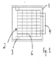
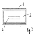
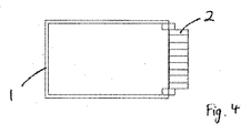
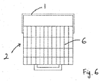
ラックモジュールは、フレーム1と、トレイ2と、を含む。フレームは、それをラック(図示せず)に搭載されるように構成されている。トレイはフレームにスライド可能及び旋回可能に搭載され、それによってトレイは第一の、閉じた位置(図1〜3に示される)と第二の、開いた位置(図4〜6に示される)との間で移動できる。
The rack module includes a frame 1 and a
第一の位置において、トレイはフレーム内に受けられ、フレームに対して実質的に平行に位置し、フレームは好ましくは、使用時に水平になるようにラック内に搭載される。第二の位置において、トレイはフレームの外で、フレームに対して斜めに位置する。ここで、第二の位置において、トレイはフレームに対して垂直に位置しているが、代替的実施形態においては、これはフレームに対して斜めに位置するように構成されてもよい。トレイは、延長線上の平行位置と図の垂直位置の間の角度範囲でロックできるように構成されてもよい。 In the first position, the tray is received in the frame and is positioned substantially parallel to the frame, and the frame is preferably mounted in the rack so that it is horizontal when in use. In the second position, the tray is located outside the frame and at an angle to the frame. Here, in the second position, the tray is positioned perpendicular to the frame, but in alternative embodiments it may be configured to be positioned at an angle to the frame. The tray may be configured so that it can be locked in an angular range between a parallel position on the extension line and a vertical position in the figure.
フレームは好ましくは、標準の19インチフレームラックの中に納まるように構成される。様々な深さのフレーム、及び従ってトレイが実現可能である。フレームの深さは、トレイがどのコンポーネントを受けるように構成されているかに大きく依存するであろう。19インチラックの規格に適合するために、フレームの最小深さは1U(1.75インチ(44.5mm))となる。しかしながら、その深さはUの倍数、即ち2U、3U、4U等であってもよい。 The frame is preferably configured to fit within a standard 19 inch frame rack. Various depth frames and thus trays are feasible. The depth of the frame will largely depend on which component the tray is configured to receive. In order to meet the 19-inch rack standard, the minimum depth of the frame is 1U (1.75 inches (44.5 mm)). However, the depth may be a multiple of U, ie 2U, 3U, 4U, etc.
フレームには好ましくは、縦に延びるその前縁から延び、固定するべきモジュール5をラックに従来の方法によりねじで固定できるようにするための縁辺または耳部(図示せず)が設けられている。
The frame is preferably provided with an edge or ear (not shown) extending from its longitudinally extending front edge so that the
フレームは、それをラック内に保持して、トレイをスライド可能及び回転可能に受けることができるようにするのに適した形態であってもよい。図のように、フレームは好ましくは、実質的に長方形である。 The frame may be in a form suitable to hold it in a rack so that the tray can be slidably and rotatably received. As shown, the frame is preferably substantially rectangular.
フレームは、前述のように、トレイを受ける。最も好ましくは、トレイはスライドレールを介してフレームに接続され、これによって、トレイとフレームの間のスライド運動、即ちトレイとフレームが相互に平行な状態のフレームの平面内での往復運動と、トレイとフレームの間の旋回運動、即ちトレイをフレームの平面に対して斜めに設置するための回転運動が可能となる。構成は、旋回運動が、トレイがスライドされてフレームの外に引き出された時にのみ可能というものである。 The frame receives the tray as described above. Most preferably, the tray is connected to the frame via a slide rail so that sliding movement between the tray, i.e. reciprocating movement in the plane of the frame with the tray and frame parallel to each other, and the tray Swivel movement between the frame and the frame, that is, rotation movement for placing the tray obliquely with respect to the plane of the frame. The configuration is such that a pivoting motion is only possible when the tray is slid and pulled out of the frame.
このような運動を可能にする、どのような適当な接続機構も利用できる。図中、接続機構3は、車輪機構として示されている。 Any suitable connection mechanism that allows such movement can be utilized. In the figure, the connection mechanism 3 is shown as a wheel mechanism.
例示的な接続機構は、第一、第二、第三、第四のペアのスライドレール部材を含む。第一のスライドレール部材はフレームに固定され、第二のペアのスライドレール部材をスライド可能に受けるように構成される。第二のペアのスライドレール部材は、第三のペアのスライドレール部材をスライド可能に受ける。第三のスライドレール部材は、第四のペアのスライドレール部材に接続される。第四のスライドレール部材はトレイに固定される。従来のストッパ手段が、第一、第二、第三のスライドレール部材が外れるのを防止するために設けられている。第三と第四のスライドレール部材は、旋回可能に相互に接続される。 An exemplary connection mechanism includes a first, second, third and fourth pair of slide rail members. The first slide rail member is fixed to the frame and is configured to slidably receive the second pair of slide rail members. The second pair of slide rail members slidably receives the third pair of slide rail members. The third slide rail member is connected to a fourth pair of slide rail members. The fourth slide rail member is fixed to the tray. Conventional stopper means are provided to prevent the first, second and third slide rail members from coming off. The third and fourth slide rail members are pivotally connected to each other.
第三と第四のスライドレール部材は、ロック可能な旋回接続手段によって接続される。接続手段によって、第三と第四のスライドレール部材が相互に平行になり、トレイがフレームに対して水平に保持され、その結果、それによってスライド可能に受けられる第一の位置が実現される。接続手段により更に、旋回設軸手段の周囲での回転運動の後に、第三と第四のスライドレール部材が平行ではなく、相互に対して斜めになる、少なくとも1つの別の位置が実現される。 The third and fourth slide rail members are connected by a lockable pivot connecting means. By means of the connecting means, the third and fourth slide rail members are parallel to each other and the tray is held horizontally with respect to the frame, thereby realizing a first position in which it can be slidably received. The connecting means further realizes at least one further position in which the third and fourth slide rail members are not parallel but are inclined relative to each other after rotational movement around the pivoting shaft means. .
最も好ましくは、この別の位置は、図4、5、6に示されるように、フレームに対して垂直である。旋回接続手段の周囲の回転運動は、スライドレール間で相対的にスライド運動して、トレイがフレームから外れた後にのみ可能となる。 Most preferably, this other position is perpendicular to the frame, as shown in FIGS. The rotational movement around the swivel connection means is only possible after the tray has been removed from the frame by relative sliding movement between the slide rails.
トレイをフレームに関して、平行と垂直の間の所望の何れの角度にもロックできるようにするロック機構を特徴とする構成が提供されてもよい。 An arrangement may be provided that features a locking mechanism that allows the tray to be locked at any desired angle between parallel and vertical with respect to the frame.
ロック可能な旋回接続手段は、どのような適当な形態をとってもよく、これは当業者であれば容易にわかるであろう。1つの可能な構成において、第四のスライドレールの各々に、離間された突起のペアが設けられ、これらは第三のスライド部材のそれぞれに設けられるそれぞれ第一と第二のスロットの中に受けられるように構成される。第一のスロットは閉じており、第三のスライド部材の長さ軸に平行に延び、第二のスロットはその上端で開放し、第一のスロットに対して実施的に垂直に延びる。このような構成によって、各ピンがそれぞれのスロットの中に位置付けられると、第三と第四のスライドレール部材は相互に平行に保持される。第二のピンが第二のスロットから外れると、第三と第四のスライドレール部材は、相互に関して旋回でき、これによって、図4〜6に示されるように、トレイがフレームに対して垂直になる。 The lockable pivot connection may take any suitable form, as will be readily appreciated by those skilled in the art. In one possible configuration, each of the fourth slide rails is provided with a pair of spaced projections that are received in respective first and second slots provided in each of the third slide members. Configured to be. The first slot is closed and extends parallel to the longitudinal axis of the third slide member, the second slot is open at its upper end and extends substantially perpendicular to the first slot. With such a configuration, the third and fourth slide rail members are held parallel to each other when each pin is positioned in a respective slot. When the second pin is out of the second slot, the third and fourth slide rail members can pivot with respect to each other so that the tray is perpendicular to the frame as shown in FIGS. Become.
第三と第四のスライドレール部材間の旋回運動は、以下のように行われる。
1)第四のスライドレールを第三のスライドレールに関して、第一のピン(第一の、閉じたスロットの中に保持される)の周囲で旋回させ、第二のピンが第二の、開いたスロットから外れるようにする。
2)第四のスライドレール部材を第三のスライドレール部材に関して、第二のピンが第三のスライドレール部材から外れるまでスライドさせる(第一のピンは第一の、閉じたスロットの中で移動する)。
3)第三と第四のレール部材を相互に関して旋回させて、第四のスライドレール部材を第三のスライドレール部材に対して垂直にする(それによってトレイは、図4〜6に示されるように、フレームに対して垂直となる)。
The turning motion between the third and fourth slide rail members is performed as follows.
1) swivel the fourth slide rail with respect to the third slide rail around the first pin (held in the first, closed slot) and the second pin is the second, open To be removed from the slot.
2) Slide the fourth slide rail member with respect to the third slide rail member until the second pin is disengaged from the third slide rail member (the first pin moves in the first, closed slot) To do).
3) swivel the third and fourth rail members relative to each other to bring the fourth slide rail member perpendicular to the third slide rail member (thereby the tray as shown in FIGS. 4-6) And perpendicular to the frame).
トレイには前面が設けられ、これは好ましくは、モジュールが第一の位置にある時には実質的に垂直であり、また、好ましくは図に示されるようにハンドル4が設けられ、使用者はこれを、スライド及び旋回運動させる時に把持してもよい。
The tray is provided with a front surface, which is preferably substantially vertical when the module is in the first position, and is preferably provided with a
トレイは上面を含み、これは、図に示されるように、トレイが第一の位置にある時にはフレームの平面に対して平行に位置し、トレイが第二の位置にある時には、フレームの平面に対して斜めに(最も好ましくは、図4〜6に示されるように垂直に)位置し、フレームから外向きになるように構成される。トレイは、トレイ内に搭載された電子コンポーネントに上面からアクセスできるように構成される。 The tray includes an upper surface, as shown in the figure, which is located parallel to the plane of the frame when the tray is in the first position, and in the plane of the frame when the tray is in the second position. It is obliquely (most preferably perpendicularly as shown in FIGS. 4-6) and is configured to face outward from the frame. The tray is configured to allow access to electronic components mounted in the tray from the top.
これは、本発明の重要な態様であり、これによって、着脱可能/点検修理可能なコンポーネントの高密度化と、更には容易なアクセスが可能となる。 This is an important aspect of the present invention, which allows for a higher density of removable / serviceable components and even easier access.
図の実施形態において、モジュールはハードディスクアレイとして構成され、これは複数の区画6(図の構成では48の区画が設けられている)を特徴とし、その各々が、トレイの上面から挿入し、取り出すことができるハードディスクドライブを着脱可能に支持するために提供され、この上面は、上で説明され、図4〜6に示されるように、トレイを旋回させることによって、アクセスしやすいように傾けてもよい。アレイのハードドライブは好ましくは、当業者であればわかるように、通常の方法でホットスワップ可能となるように構成される。ハードディスクドライブは、区画によって受けられるように構成されたケースの中に設置されてもよい。トレイは、必要なデータ及び電源接続が各区画の中で提供されるように構成される。 In the illustrated embodiment, the module is configured as a hard disk array, which features a plurality of compartments 6 (48 compartments are provided in the configuration shown), each of which is inserted and removed from the top surface of the tray. Provided to removably support a hard disk drive, and this top surface can be tilted for easy access by swiveling the tray as described above and shown in FIGS. Good. The hard drives of the array are preferably configured to be hot swappable in a conventional manner, as will be appreciated by those skilled in the art. The hard disk drive may be installed in a case configured to be received by the compartment. The tray is configured so that the necessary data and power connections are provided in each compartment.
しかしながら、当然のことながら、本発明はハードディスクアレイに限定されない。 However, it should be understood that the present invention is not limited to hard disk arrays.
上述のモジュールは、1つのトレイを受けるためのフレームを含むが、各フレームによって複数のトレイが受けられるようにすることも可能である。フレームは、2つ以上のトレイを横並びに、及び/または積み重ね式に受けるように構成されてもよい。 The module described above includes a frame for receiving a single tray, but each frame may receive a plurality of trays. The frame may be configured to receive two or more trays side by side and / or in a stacked manner.
当業者であれば容易にわかるように、ラックの他の構成も可能である。例えば、当業者には、別のスライド/旋回機構も容易に想定されるであろう。 Other configurations of the rack are possible, as will be readily appreciated by those skilled in the art. For example, those skilled in the art will readily envision other slide / swivel mechanisms.
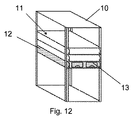
図7〜23を参照すると、本発明による別のラックモジュールが示されている。いくつかの図では、本発明によるラックモジュール11がラック10の中で使用されていることがわかり、ラックユニットを提供している。
7-23, another rack module according to the present invention is shown. In some of the figures, it can be seen that the
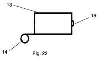
ラックモジュール11は、フレーム12と、トレイ13と、を含む。フレームは、それがラック10の中に搭載されるように構成される。トレイはフレームにスライド可能及び旋回可能に搭載され、それによってトレイは第一の、閉じた位置(図12と17に示される)と第二の、開いた位置(図7、9、11、13、15、18、21に示される)の間で移動できる。図8、10、14、20から、トレイが、トレイが部分的または完全にフレームからスライドされて引き出されているが、旋回されていない位置を介して、第一と第二の位置間で移動することがわかる。
The
第一の位置において、トレイはフレームの中に受けられ、フレームに対して実質的に平行に位置し、フレームは好ましくは、ラックの中に、それが使用中に水平になるように搭載される。第二の位置において、トレイはフレームの外で、フレームに対して斜めに位置する。第二の位置でトレイはフレームに対して垂直に位置してもよいことがわかる(図7、11、13、15、18、21に示される)が、代替的実施形態では、これはフレームに対して斜めの角度に位置するように(図9のように)構成されてもよい。 In the first position, the tray is received in the frame and is positioned substantially parallel to the frame, and the frame is preferably mounted in the rack so that it is horizontal during use. . In the second position, the tray is located outside the frame and at an angle to the frame. It will be appreciated that in the second position the tray may be positioned perpendicular to the frame (shown in FIGS. 7, 11, 13, 15, 18, 21), but in an alternative embodiment this is in the frame. On the other hand, it may be configured to be positioned at an oblique angle (as shown in FIG. 9).
トレイは、それが延長線上の平行位置とフレームの外の垂直位置またはその他の位置との間の角度範囲で、及びフレームに対してある角度でロックできるように構成されてもよい。 The tray may be configured so that it can lock at an angular range between a parallel position on the extension and a vertical position or other position outside the frame, and at an angle to the frame.
脚17が(図9に示されるように)トレイに設けられてもよい。脚は、トレイがその第二の位置にある時に、脚がラックの外面と背接触するように位置付けられてもよい。図9からわかるように、脚は、トレイの下面から延び、トレイの前面に、またはその付近に位置付けられてもよい。
脚は、トレイが偶発的にその背後の何かにぶつかるのを防止するために使用することができる。脚は、図9に示されるように、第二の位置にある時のトレイをわずかに斜めにするために使用してもよい。 The legs can be used to prevent the tray from accidentally hitting something behind it. The legs may be used to slightly tilt the tray when in the second position, as shown in FIG.
フレームは好ましくは、標準の19インチフレームラックの中に納まるように構成される。様々な深さのフレーム、及び従ってトレイが実現可能である。フレームの深さは、トレイがどのコンポーネントを受けるように構成されているかに大きく依存するであろう。19インチラックの規格に適合するために、フレームの最小深さは1U(1.75インチ(44.5mm))となる。しかしながら、その深さはUの倍数、即ち2U、3U、4U等であってもよい。 The frame is preferably configured to fit within a standard 19 inch frame rack. Various depth frames and thus trays are feasible. The depth of the frame will largely depend on which component the tray is configured to receive. In order to meet the 19-inch rack standard, the minimum depth of the frame is 1U (1.75 inches (44.5 mm)). However, the depth may be a multiple of U, ie 2U, 3U, 4U, etc.
フレームには好ましくは、縦に延びるその前縁から延び、固定するべきモジュールをラックに従来の方法によりねじまたはその他の固定手段で固定できるようにするための縁または耳部(図示せず)が設けられている。 The frame preferably has an edge or ear (not shown) extending from its longitudinally extending front edge so that the module to be secured can be secured to the rack by screws or other securing means in a conventional manner. Is provided.
フレームは、それをラック内に保持して、トレイをスライド可能及び回転可能に受けることができるようにするのに適した形態であってもよい。図のように、フレームは好ましくは、実質的に長方形である。 The frame may be in a form suitable to hold it in a rack so that the tray can be slidably and rotatably received. As shown, the frame is preferably substantially rectangular.
フレームは、前述のように、トレイを受け、トレイはフレームにスライド可能及び旋回可能に接続される。 The frame receives the tray as described above, and the tray is slidably and pivotally connected to the frame.
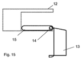
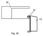
トレイは、どのようなスライド機構を用いて、スライド可能にフレームから出て、スライド可能にフレームの中に戻るようにしてもよい。図7〜11と14〜22は各種の適当なスライド機構を示しているが、これらは限定的ではない。スライド機構は好ましくは、トレイの下面に、及び/または、トレイの下面と係合するようにフレームの内側に位置付けられることがわかる。 The tray may be slidably out of the frame and slidably back into the frame using any slide mechanism. 7-11 and 14-22 show various suitable slide mechanisms, these are not limiting. It can be seen that the sliding mechanism is preferably positioned on the underside of the tray and / or on the inside of the frame to engage the underside of the tray.
好ましくは、スライド機構には軸受手段14、例えば車輪、キャスター、ローラーまたはその他を設置することが関わる。これらは、トレイの下面に、及び/または、トレイの下面と係合するようにフレームの内側に設置される。図は、軸受手段を車輪として示しているが、当然のことながら、これは軸受手段としての唯一の使用可能な選択肢ではない。 Preferably, the sliding mechanism involves installing bearing means 14, such as wheels, casters, rollers or the like. These are placed on the bottom surface of the tray and / or inside the frame to engage the bottom surface of the tray. Although the figure shows the bearing means as a wheel, it will be appreciated that this is not the only usable option as a bearing means.
好ましくは、スライド機構は、トレイのスライドを支援する案内手段15を含む。これらは、レールまたは溝またはトラックまたはその他であってもよい。図は、案内手段をトラックまたはスライドレールとして示しているが、当然のことながら、これは案内手段としての唯一の使用可能な選択肢ではない。 Preferably, the slide mechanism includes guide means 15 for supporting the slide of the tray. These may be rails or grooves or tracks or others. Although the figure shows the guide means as a track or slide rail, it will be appreciated that this is not the only available option as a guide means.
トレイは、どのような旋回機構を使ってフレームに関して旋回するようにしてもよい。旋回機構には、軸受手段14、例えば車輪、キャスター、ローラー、またはその他の周囲での旋回が関わることが好ましい。 The tray may be pivoted with respect to the frame using any pivoting mechanism. The swiveling mechanism preferably involves swiveling around the bearing means 14, such as wheels, casters, rollers, or other surroundings.
好ましくは、旋回軸14の位置は、トレイの上面の後縁から垂直に延ばした位置に整列するか、その背後にある(例えば、図8/9、15/16参照)。1つの実施形態において、旋回軸の位置はトレイの下面の後縁にある。
Preferably, the position of the
1つの実施形態において、トレイはスライドレールを介してフレームに接続され、これによって、トレイとフレームの間のスライド運動、即ちトレイとフレームが相互に平行な状態のフレームの平面内での往復運動と、トレイとフレームの間の旋回運動、即ちトレイをフレームの平面に対して斜めに設置するための回転運動が可能となる。構成は、旋回運動が、トレイがスライドされてフレームの外に引き出された時にのみ可能というものである。このような運動を可能にする、どのような適当な接続機構も利用できる。図中、接続機構は車輪機構として示されている。 In one embodiment, the tray is connected to the frame via a slide rail so that sliding movement between the tray and the frame, i.e. reciprocation in the plane of the frame with the tray and frame parallel to each other, Rotating motion between the tray and the frame, that is, rotational motion for installing the tray obliquely with respect to the plane of the frame is possible. The configuration is such that a pivoting motion is only possible when the tray is slid and pulled out of the frame. Any suitable connection mechanism that allows such movement can be utilized. In the figure, the connection mechanism is shown as a wheel mechanism.
旋回接続手段の周囲の回転は、案内手段に関して相対的にスライド運動し、トレイがフレームから外れた後にのみ可能となる。 Rotation around the swivel connection means is only possible after sliding relative to the guide means and after the tray has been removed from the frame.
前述のように、トレイをフレームに関して、平行と垂直の間の何れの所望の角度にもロックできるようにするロック機構を特徴とする構成が提供されてもよい。ロック可能な旋回接続手段は、当業者であれば容易にわかるように、どのような適当な形態をとってもよい。 As previously described, an arrangement may be provided that features a locking mechanism that allows the tray to be locked with respect to the frame at any desired angle between parallel and vertical. The lockable pivot connection means may take any suitable form, as will be readily appreciated by those skilled in the art.
いくつかの実施形態において、スライド機構は図20と21に示されるように、ストッパ18を含んでいてもよい。
In some embodiments, the slide mechanism may include a
本発明のモジュールは、トレイが、トレイがフレーム中に受けられ、フレームに対して実質的に平行に位置するその第一の位置にある時に閉じた箱を形成する。図からわかるように、トレイは少なくともその上面において開放し(これは、トレイ内に設置された機器にアクセスできる点で有利である)、フレームは少なくとも1つの端で開放し(これにより、トレイを第一と第二の位置の間でフレームに出入りするように移動できる)が、トレイがその第一の位置にある状態でのトレイとフレームの組み合わせにより、結果的な本発明のモジュールは閉じた箱を形成する。 The module of the present invention forms a closed box when the tray is in its first position where the tray is received in the frame and located substantially parallel to the frame. As can be seen, the tray is open at least on its top surface (which is advantageous in that it allows access to equipment installed in the tray), and the frame is open at at least one end (which allows the tray to be opened). Can move in and out of the frame between the first and second positions), but the combination of the tray and the frame with the tray in its first position closed the resulting module of the present invention Form a box.
トレイには前面が提供され、これは好ましくは、モジュールが第一の位置にある時に実質的に垂直であり、これには好ましくは、図に示されるようにハンドル16が設けられ、使用者はこれを、スライド及び水平運動させる際に把持してもよい。
The tray is provided with a front surface, which is preferably substantially vertical when the module is in the first position, and is preferably provided with a
トレイは上面を含み、これは、図に示されるように、トレイが第一の位置にある時にフレームの平面に対して平行に位置し、トレイが第二の位置にある時には、フレームの平面に対して斜め(最も好ましくは、図4〜6に示されるように垂直)に位置し、フレームから外向きになるように構成される。トレイは、トレイ内に搭載される電子コンポーネントに上面からアクセスできるように構成される。 The tray includes an upper surface, as shown in the figure, which is parallel to the plane of the frame when the tray is in the first position and is in the plane of the frame when the tray is in the second position. It is diagonally (most preferably vertical as shown in FIGS. 4-6) and is configured to face outward from the frame. The tray is configured to allow access to electronic components mounted in the tray from the top.
これは、本発明の重要な態様であり、これによって、着脱可能/点検修理可能なコンポーネントの高密度化と、更には容易なアクセスが可能となる。 This is an important aspect of the present invention, which allows for a higher density of removable / serviceable components and even easier access.
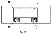
図12と13において、モジュールはハードディスクアレイとして構成される。これらの図に示される製品は、本発明によるラック10を含むハードディスクドライブユニットであり、その中で、モジュール11の1つ以上がそのトレイ13内に位置付けられたハードディスクドライブ19を有する。
12 and 13, the module is configured as a hard disk array. The product shown in these figures is a hard disk drive unit that includes a
トレイは複数の区画を含んでいてもよく、その各々は、トレイの上面から挿入し、取り出すことのできるハードディスクドライブを着脱可能に支持するために設けられ、この上面は、前述のように、トレイを旋回させることによって、アクセスしやすいように斜めにしてもよい。 The tray may include a plurality of compartments, each of which is provided to detachably support a hard disk drive that can be inserted and removed from the top surface of the tray, the top surface as described above. May be tilted for easy access by turning.
アレイのハードドライブは好ましくは、当業者であればわかるように、通常の方法でホットスワップ可能になるように構成される。ハードディスクドライブは、区画により受けられるように構成されたケースの中に設置されてもよい。トレイは、必要なデータ及び電源接続が各区画内に提供されるように構成される。 The hard drives of the array are preferably configured to be hot swappable in a conventional manner, as will be appreciated by those skilled in the art. The hard disk drive may be installed in a case configured to be received by the compartment. The tray is configured so that the necessary data and power connections are provided within each compartment.
しかしながら、当然のことながら、本発明はハードディクスアレイに限定されない。 However, it should be understood that the present invention is not limited to hard disk arrays.
上で説明し、図に示したモジュールは、1つのトレイまたは2つのトレイを受けるための1つのフレームを含んでいるが、各フレームにより他の数のトレイが受けられるようにすることもできる。図12と13は、2つのトレイが横並びの構成で設置されている実施形態を示しているが、当然のことながら、フレームは、2つ以上のトレイ(例えば、3つ以上または4つ以上のトレイ)を横並び及び/または積み重ねの構成で受けるように構成されてもよい。 The modules described above and shown in the figures include one frame for receiving one tray or two trays, but each frame can receive another number of trays. 12 and 13 illustrate an embodiment in which two trays are installed in a side-by-side configuration, it will be appreciated that the frame may have more than two trays (eg, more than two or more than four). Trays) may be configured to receive in a side-by-side and / or stacked configuration.
当業者であれば容易にわかるように、ラックの別の構成も可能である。例えば、他のスライド/旋回機構も当業者には容易に想定されるであろう。 Other configurations of the rack are possible as will be readily appreciated by those skilled in the art. For example, other slide / swivel mechanisms will be readily envisioned by those skilled in the art.
Claims (22)
フレームと、トレイと、を含み、前記フレームが、それを前記ラックに搭載できるように構成され、前記トレイが前記フレームにスライド可能及び旋回可能に接続され、それによって前記トレイは、前記トレイが前記フレーム内に受けられ、前記フレームに対して実質的に平行に位置する第一の位置と、前記トレイが前記フレームの外で、前記フレームに対して斜めに位置する第二の位置との間で移動可能であることを特徴とするモジュール。 In modules for rack mounting,
A frame and a tray, wherein the frame is configured to allow it to be mounted on the rack, the tray being slidably and pivotally connected to the frame, whereby the tray has the tray Between a first position received within the frame and located substantially parallel to the frame and a second position at which the tray is located obliquely to the frame outside the frame. A module characterized by being movable.
前記トレイが上面を含み、これは、前記トレイが前記第一の位置にある時は前記フレームの平面に対して平行に位置し、前記トレイが前記第二の位置にある時には、前記フレームの平面に対して斜めに位置し、前記フレームから外向きになるように構成され、前記トレイが、前記トレイ内に搭載されたコンポーネントに前記上面からアクセスできるように構成されることを特徴とするモジュール。 The module of claim 1, wherein
The tray includes an upper surface, which is positioned parallel to the plane of the frame when the tray is in the first position and the plane of the frame when the tray is in the second position. The module is configured to be inclined with respect to the frame and to face outward from the frame, and the tray is configured to be accessible from the top surface to components mounted in the tray.
前記トレイが、前記コンポーネントを前記上面から取り出せるように構成されることを特徴とするモジュール。 The module of claim 2,
A module wherein the tray is configured to allow the component to be removed from the top surface.
前記トレイが、前記第二の位置において、前記トレイが前記フレームに対して垂直に位置するように構成されることを特徴とするモジュール。 The module according to any one of claims 1 to 3,
The module is configured such that the tray is positioned perpendicular to the frame at the second position.
前記トレイ内に1つ以上のホットスワップ可能な電子コンポーネントが搭載されることを特徴とするモジュール。 The module according to any one of claims 1 to 4,
A module comprising one or more hot-swappable electronic components mounted in the tray.
前記モジュールが、複数のハードディスクドライブを含むハードディスクアレイであることを特徴とするモジュール。 The module according to any one of claims 1 to 5,
The module is a hard disk array including a plurality of hard disk drives.
前記トレイが複数の区画を含み、各区画が、電子コンポーネントを着脱可能に支持し、前記コンポーネントとの必要な接続を提供するように設けられることを特徴とするモジュール。 The module according to any one of claims 1 to 6,
The module, wherein the tray includes a plurality of compartments, each compartment being detachably supported for electronic components and provided with the necessary connections with the components.
各区画が、ハードディスクドライブを受け、その中に前記ハードディスクドライブを支持し、前記ハードドライブとの必要な電源及びデータ接続を提供するように構成されることを特徴とするモジュール。 The module of claim 7 when dependent on claim 6,
A module wherein each partition is configured to receive a hard disk drive, support the hard disk drive therein, and provide the necessary power and data connection with the hard drive.
前記フレームが、19インチラック内に搭載されるように構成されることを特徴とするモジュール。 The module according to any one of claims 1 to 8,
A module wherein the frame is configured to be mounted in a 19 inch rack.
前記フレームの高さが1Uまたはその倍数であることを特徴とするモジュール。 The module of claim 9,
The module is characterized in that the height of the frame is 1U or a multiple thereof.
前記モジュールの幅にわたって複数のトレイがあることを特徴とするモジュール。 The module according to any one of claims 1 to 10,
A module having a plurality of trays across the width of the module.
前記トレイがその第一の位置にある時に、前記モジュールが閉じた箱を形成することを特徴とするモジュール。 The module according to any one of claims 1 to 11,
A module wherein the module forms a closed box when the tray is in its first position.
前記トレイが前記フレームに関して、軸受手段を中心に旋回することを特徴とするモジュール。 The module according to any one of claims 1 to 12,
A module wherein the tray pivots about bearing means with respect to the frame.
前記トレイが前記フレームに関して、前記トレイの前記上面の後縁から垂直に延ばした位置に整列するか、その背後にあるか何れかの転心の周囲で旋回することを特徴とするモジュール。 The module according to any one of claims 1 to 13,
A module wherein the tray is aligned with a position extending perpendicularly from a trailing edge of the top surface of the tray with respect to the frame or pivots about a center of rotation behind or behind it.
前記トレイの前記後面が、前記トレイの前記下面に対して鋭角であることを特徴とするモジュール。 The module according to any one of claims 1 to 14,
The module, wherein the rear surface of the tray has an acute angle with respect to the lower surface of the tray.
前記ラックが2つ以上の空洞を含み、その中に1つ以上のモジュールが納まることを特徴とするラックユニット。 The rack unit according to claim 16, wherein
A rack unit, wherein the rack includes two or more cavities, and one or more modules are accommodated therein.
前記ラックが2つ以上の空洞を含み、各空洞の中に1つ以上のモジュールが搭載されることを特徴とするラックユニット。 The rack unit according to claim 17,
The rack unit includes two or more cavities, and one or more modules are mounted in each of the cavities.
前記空洞の各々の高さが1Uの倍数であることを特徴とするラックユニット。 The rack unit according to claim 17 or 18,
A rack unit, wherein the height of each of the cavities is a multiple of 1U.
前記ラックの幅にわたり複数のトレイがあることを特徴とするラックユニット。 The rack unit according to any one of claims 16 to 19,
A rack unit having a plurality of trays across the width of the rack.
前記モジュールの1つ以上が、そのトレイ内に位置付けられたハードディスクドライブを有することを特徴とするハードディスクドライブユニット。 A hard disk drive unit including the rack unit according to any one of claims 16 to 20,
A hard disk drive unit, wherein one or more of the modules has a hard disk drive positioned in its tray.
Applications Claiming Priority (3)
| Application Number | Priority Date | Filing Date | Title |
|---|---|---|---|
| GB1107860.7 | 2011-05-11 | ||
| GBGB1107860.7A GB201107860D0 (en) | 2011-05-11 | 2011-05-11 | Rack module |
| PCT/GB2012/051028 WO2012153141A1 (en) | 2011-05-11 | 2012-05-10 | Rack module |
Publications (2)
| Publication Number | Publication Date |
|---|---|
| JP2014513376A true JP2014513376A (en) | 2014-05-29 |
| JP2014513376A5 JP2014513376A5 (en) | 2015-07-09 |
Family
ID=44243940
Family Applications (1)
| Application Number | Title | Priority Date | Filing Date |
|---|---|---|---|
| JP2014509826A Pending JP2014513376A (en) | 2011-05-11 | 2012-05-10 | Rack module |
Country Status (13)
| Country | Link |
|---|---|
| US (2) | US9516777B2 (en) |
| EP (1) | EP2710867A1 (en) |
| JP (1) | JP2014513376A (en) |
| KR (1) | KR20140041536A (en) |
| CN (1) | CN103650654A (en) |
| AU (2) | AU2012252171A1 (en) |
| BR (1) | BR112013028752A2 (en) |
| CA (1) | CA2872438A1 (en) |
| GB (4) | GB201107860D0 (en) |
| MX (1) | MX349831B (en) |
| RU (1) | RU2013152334A (en) |
| SG (1) | SG2014001564A (en) |
| WO (1) | WO2012153141A1 (en) |
Cited By (2)
| Publication number | Priority date | Publication date | Assignee | Title |
|---|---|---|---|---|
| JP2017005065A (en) * | 2015-06-09 | 2017-01-05 | 新電元工業株式会社 | Electronic apparatus |
| JP2021502519A (en) * | 2017-11-13 | 2021-01-28 | エドワーズ リミテッド | Modules for vacuum pumps and / or abatement systems |
Families Citing this family (31)
| Publication number | Priority date | Publication date | Assignee | Title |
|---|---|---|---|---|
| GB201107860D0 (en) * | 2011-05-11 | 2011-06-22 | Manda Ion | Rack module |
| FR3000030B1 (en) * | 2012-12-21 | 2016-03-04 | Airbus Operations Sas | ELECTRICAL AND ELECTRONIC COMPARTMENT OF AN AIRCRAFT WITH AN IMPROVED ARCHITECTURE AND AN AIRCRAFT INCORPORATING THIS COMPARTMENT. |
| US9001514B2 (en) * | 2013-01-23 | 2015-04-07 | Dot Hill Systems Corporation | Safe rackmountable storage enclosure |
| US9763350B2 (en) * | 2013-01-23 | 2017-09-12 | Seagate Technology Llc | High density data storage system with improved storage device access |
| KR101623347B1 (en) * | 2013-12-30 | 2016-06-07 | 주식회사 효성 | Module withdrawing apparatus for HVDC system |
| TWI574602B (en) | 2014-01-16 | 2017-03-11 | 廣達電腦股份有限公司 | Server |
| WO2015122898A1 (en) | 2014-02-13 | 2015-08-20 | Hewlett-Packard Development Company, L.P. | Handle mechanism |
| US9635776B2 (en) * | 2014-04-25 | 2017-04-25 | Hong Fu Jin Precision Industry (Shenzhen) Co., Ltd. | Cabinet |
| US9173312B1 (en) | 2014-04-30 | 2015-10-27 | Quanta Computer Inc. | Cable storage under a drawer |
| US9854698B2 (en) | 2014-06-20 | 2017-12-26 | Hewlett Packard Enterprise Development Lp | Support member |
| TWI512438B (en) * | 2014-09-12 | 2015-12-11 | Quanta Comp Inc | Server device |
| CA2911343A1 (en) | 2014-11-06 | 2016-05-06 | Cinnos Technologies, Inc. | Smart mission critical rack |
| CN104536539A (en) * | 2014-12-04 | 2015-04-22 | 英业达科技有限公司 | Electronic device |
| US9491884B2 (en) * | 2015-01-15 | 2016-11-08 | Aic Inc. | Server cabinet drawer structure |
| FR3043850B1 (en) * | 2015-11-17 | 2017-12-15 | Legrand France | BREWING PANEL COMPRISING A DRAWER ATTACHING DEVICE |
| CN105425919B (en) * | 2015-12-17 | 2019-04-16 | 英业达科技有限公司 | A kind of server system and its position-limit mechanism of application |
| CN107402604A (en) * | 2016-05-20 | 2017-11-28 | 环旭电子股份有限公司 | The track groups of server shell |
| US11027366B2 (en) | 2016-08-26 | 2021-06-08 | Nlight, Inc. | Laser power distribution module |
| CN106647966B (en) * | 2016-12-02 | 2019-09-17 | 英业达科技有限公司 | Server |
| US10362706B2 (en) * | 2017-04-19 | 2019-07-23 | Hewlett Packard Enterprise Development Lp | Server systems with hinge mechanisms |
| US11019753B2 (en) * | 2017-06-27 | 2021-05-25 | Microsoft Technology Licensing, Llc | Cooling electronic devices within a data center |
| US20190044809A1 (en) * | 2017-08-30 | 2019-02-07 | Intel Corporation | Technologies for managing a flexible host interface of a network interface controller |
| GB2568493A (en) * | 2017-11-16 | 2019-05-22 | Moog Unna Gmbh | Pitch drive control module with sub-module |
| US10631431B2 (en) * | 2017-12-18 | 2020-04-21 | Quanta Computer Inc. | Low down seismic shock rack design |
| TWI668686B (en) * | 2018-02-13 | 2019-08-11 | 神雲科技股份有限公司 | Server system |
| TWI658772B (en) * | 2018-03-02 | 2019-05-01 | 緯創資通股份有限公司 | Electronic device and positioning structure capable of positioning casing |
| US11071228B2 (en) * | 2018-09-26 | 2021-07-20 | Apple Inc. | Computing workstation with accessible in a rack environment |
| TWI708543B (en) * | 2019-12-02 | 2020-10-21 | 友達光電股份有限公司 | Housing and electronic device thereof |
| US10939581B1 (en) * | 2020-01-15 | 2021-03-02 | Quanta Computer Inc. | Immersion liquid cooling rack |
| RU2763157C2 (en) * | 2020-02-14 | 2021-12-27 | Общество С Ограниченной Ответственностью «Яндекс» | Frame structure |
| US11308990B1 (en) * | 2020-10-16 | 2022-04-19 | Seagate Technology Llc | Selectively routing signals to data storage devices within a data storage system that includes a movable carriage |
Citations (5)
| Publication number | Priority date | Publication date | Assignee | Title |
|---|---|---|---|---|
| US5506750A (en) * | 1993-04-22 | 1996-04-09 | Bull S.A. | Mass memory subsystem having plates with pluralities of disk drives connected to central electronic cards |
| JP2000348475A (en) * | 1999-06-03 | 2000-12-15 | Sony Corp | Data recording/reproducing apparatus |
| JP2003036669A (en) * | 2001-07-13 | 2003-02-07 | Internatl Business Mach Corp <Ibm> | Electronic equipment and rack for storing electronic equipment |
| US20060010456A1 (en) * | 2004-07-08 | 2006-01-12 | Fujitsu Limited | Rack mount type storage unit enabling easy access |
| US6999306B2 (en) * | 2003-08-21 | 2006-02-14 | Hewlett-Packard Development Company, L.P. | Method and system and apparatus for storing data storage devices |
Family Cites Families (33)
| Publication number | Priority date | Publication date | Assignee | Title |
|---|---|---|---|---|
| US2566064A (en) | 1946-10-21 | 1951-08-28 | Gen Electric | Cabinet construction |
| DE1183157B (en) * | 1960-10-22 | 1964-12-10 | Calor Emag Elektrizitaets Ag | Control cabinet with drawer-like device combinations |
| US3586410A (en) * | 1969-10-24 | 1971-06-22 | James E Barrow | File cabinet ii |
| DE3426102A1 (en) * | 1984-07-16 | 1986-01-16 | Siemens AG, 1000 Berlin und 8000 München | Holder for a mounting rack |
| FR2622365B1 (en) * | 1987-10-23 | 1990-12-07 | Scle Sarl | HOUSING FOR THE EQUIPMENT OF AN ELECTRICAL POWER DISTRIBUTION CABINET |
| US5584396A (en) * | 1995-05-17 | 1996-12-17 | Dell Usa Lp | Sliding pivoting storage apparatus |
| US6988626B2 (en) * | 1998-07-31 | 2006-01-24 | Varghese Paily T | Computer component rack mounting arrangement |
| US6621693B1 (en) * | 2000-07-05 | 2003-09-16 | Network Engines, Inc. | Low profile, high density storage array |
| US6535391B2 (en) * | 2001-04-26 | 2003-03-18 | International Business Machines Corporation | Cage assembly for front service access and method of use |
| US20020171334A1 (en) * | 2001-05-15 | 2002-11-21 | Pinheiro Antonio Adjuto | Drawer for cabinet of microcomputer |
| US6892275B2 (en) * | 2002-02-05 | 2005-05-10 | Quantum Corporation | Storage system utilizing an active subset of drives during data storage and retrieval operations |
| US6826055B2 (en) * | 2003-03-17 | 2004-11-30 | Unisys Corporation | Movable module for computer system and method of use |
| US6788544B1 (en) * | 2003-04-11 | 2004-09-07 | Hewlett-Packard Development Company, L.P. | Field replaceable unit access device and method |
| US7042721B2 (en) * | 2003-09-22 | 2006-05-09 | Sun Microsystems, Inc. | Electronic assembly including a housing having a rotatable portion |
| WO2005088427A1 (en) * | 2004-03-15 | 2005-09-22 | Powerdsine, Ltd. | High density front access device |
| US20050265013A1 (en) * | 2004-06-01 | 2005-12-01 | Keith Scott M | Modular communications shelf system and methods for using the same |
| JP2006179650A (en) * | 2004-12-22 | 2006-07-06 | Roland Corp | Electronic instrument |
| WO2006129350A1 (en) * | 2005-05-31 | 2006-12-07 | Fujitsu Limited | Communication device, information processing device, and connection method of line wire cables |
| US7423870B2 (en) | 2005-11-18 | 2008-09-09 | International Business Machines Corporation | Blade server assembly |
| US7916423B2 (en) * | 2006-03-31 | 2011-03-29 | Spectra Logic Corporation | High density array system with active movable media drawers |
| US7769266B2 (en) * | 2006-06-23 | 2010-08-03 | Adc Gmbh | Slide and tilt mechanism for a telecommunications panel |
| US7474229B2 (en) * | 2006-09-13 | 2009-01-06 | Hewlett-Packard Development Company, L.P. | Computer system indicator panel with exposed indicator edge |
| CN201083654Y (en) * | 2007-09-05 | 2008-07-09 | 苏州试验仪器总厂 | Integral control cabinet |
| US8014156B2 (en) * | 2008-04-10 | 2011-09-06 | Netapp, Inc. | Storage blade |
| US8433063B2 (en) | 2008-09-08 | 2013-04-30 | Ortronics, Inc. | Horizontal copper patching assembly |
| GB2467622B (en) * | 2008-12-23 | 2011-12-14 | Nexsan Technologies Ltd | Data storage apparatus |
| GB0823407D0 (en) * | 2008-12-23 | 2009-01-28 | Nexan Technologies Ltd | Apparatus for storing data |
| US8538226B2 (en) * | 2009-05-21 | 2013-09-17 | Corning Cable Systems Llc | Fiber optic equipment guides and rails configured with stopping position(s), and related equipment and methods |
| CN201489427U (en) * | 2009-07-21 | 2010-05-26 | 英业达股份有限公司 | Server device with stretchable support arm |
| DE202010007778U1 (en) * | 2010-06-09 | 2010-10-07 | CCS Technology, Inc., Wilmington | Device for handling data conductors |
| WO2012063280A1 (en) * | 2010-11-09 | 2012-05-18 | Hitachi, Ltd. | Structual fabric of a storage apparatus for mounting storage devices |
| GB201107860D0 (en) * | 2011-05-11 | 2011-06-22 | Manda Ion | Rack module |
| US8797732B2 (en) * | 2012-03-05 | 2014-08-05 | Hewlett-Packard Development Company, L.P. | Server backplane |
-
2011
- 2011-05-11 GB GBGB1107860.7A patent/GB201107860D0/en not_active Ceased
-
2012
- 2012-05-10 BR BR112013028752A patent/BR112013028752A2/en not_active IP Right Cessation
- 2012-05-10 SG SG2014001564A patent/SG2014001564A/en unknown
- 2012-05-10 CN CN201280033325.9A patent/CN103650654A/en active Pending
- 2012-05-10 RU RU2013152334/07A patent/RU2013152334A/en not_active Application Discontinuation
- 2012-05-10 EP EP12728106.1A patent/EP2710867A1/en not_active Withdrawn
- 2012-05-10 AU AU2012252171A patent/AU2012252171A1/en not_active Abandoned
- 2012-05-10 KR KR1020137032677A patent/KR20140041536A/en not_active Application Discontinuation
- 2012-05-10 GB GB1208233.5A patent/GB2491453B/en not_active Expired - Fee Related
- 2012-05-10 GB GB1501682.7A patent/GB2525959B/en not_active Expired - Fee Related
- 2012-05-10 MX MX2013013155A patent/MX349831B/en active IP Right Grant
- 2012-05-10 JP JP2014509826A patent/JP2014513376A/en active Pending
- 2012-05-10 WO PCT/GB2012/051028 patent/WO2012153141A1/en active Application Filing
- 2012-05-10 US US14/116,920 patent/US9516777B2/en active Active
- 2012-05-10 CA CA2872438A patent/CA2872438A1/en not_active Abandoned
-
2015
- 2015-08-10 GB GBGB1514097.3A patent/GB201514097D0/en not_active Ceased
-
2016
- 2016-10-26 US US15/334,742 patent/US9943002B2/en not_active Expired - Fee Related
- 2016-11-28 AU AU2016262793A patent/AU2016262793A1/en not_active Abandoned
Patent Citations (6)
| Publication number | Priority date | Publication date | Assignee | Title |
|---|---|---|---|---|
| US5506750A (en) * | 1993-04-22 | 1996-04-09 | Bull S.A. | Mass memory subsystem having plates with pluralities of disk drives connected to central electronic cards |
| JP2000348475A (en) * | 1999-06-03 | 2000-12-15 | Sony Corp | Data recording/reproducing apparatus |
| JP2003036669A (en) * | 2001-07-13 | 2003-02-07 | Internatl Business Mach Corp <Ibm> | Electronic equipment and rack for storing electronic equipment |
| US6999306B2 (en) * | 2003-08-21 | 2006-02-14 | Hewlett-Packard Development Company, L.P. | Method and system and apparatus for storing data storage devices |
| US20060010456A1 (en) * | 2004-07-08 | 2006-01-12 | Fujitsu Limited | Rack mount type storage unit enabling easy access |
| JP2006024283A (en) * | 2004-07-08 | 2006-01-26 | Fujitsu Ltd | Rack-mounting storage unit and rack-mounting disk array device |
Cited By (3)
| Publication number | Priority date | Publication date | Assignee | Title |
|---|---|---|---|---|
| JP2017005065A (en) * | 2015-06-09 | 2017-01-05 | 新電元工業株式会社 | Electronic apparatus |
| JP2021502519A (en) * | 2017-11-13 | 2021-01-28 | エドワーズ リミテッド | Modules for vacuum pumps and / or abatement systems |
| JP7373493B2 (en) | 2017-11-13 | 2023-11-02 | エドワーズ リミテッド | Modules for vacuum pumps and/or abatement systems |
Also Published As
| Publication number | Publication date |
|---|---|
| US20170049002A1 (en) | 2017-02-16 |
| RU2013152334A (en) | 2015-06-20 |
| MX2013013155A (en) | 2014-07-14 |
| US9516777B2 (en) | 2016-12-06 |
| GB2525959B (en) | 2015-12-30 |
| AU2012252171A1 (en) | 2014-01-09 |
| GB201208233D0 (en) | 2012-06-20 |
| GB2491453A (en) | 2012-12-05 |
| GB2491453B (en) | 2015-06-17 |
| SG2014001564A (en) | 2014-04-28 |
| CA2872438A1 (en) | 2012-11-15 |
| US9943002B2 (en) | 2018-04-10 |
| KR20140041536A (en) | 2014-04-04 |
| EP2710867A1 (en) | 2014-03-26 |
| GB2491453A8 (en) | 2013-12-11 |
| MX349831B (en) | 2017-08-14 |
| GB201501682D0 (en) | 2015-03-18 |
| GB2525959A (en) | 2015-11-11 |
| WO2012153141A1 (en) | 2012-11-15 |
| GB201514097D0 (en) | 2015-09-23 |
| BR112013028752A2 (en) | 2017-11-07 |
| AU2016262793A1 (en) | 2016-12-15 |
| CN103650654A (en) | 2014-03-19 |
| US20140055959A1 (en) | 2014-02-27 |
| GB201107860D0 (en) | 2011-06-22 |
Similar Documents
| Publication | Publication Date | Title |
|---|---|---|
| JP2014513376A (en) | Rack module | |
| US10476285B2 (en) | Tablet storage and transportation device | |
| US9007766B2 (en) | Storage enclosure with pivotably mounted midplane assembly | |
| US10237998B2 (en) | System with movable computing devices | |
| US7362565B2 (en) | Disk drive support system | |
| JP5622221B2 (en) | Storage unit for electronic devices | |
| US6168250B1 (en) | Flat panel monitor mounting assembly | |
| WO2014122650A1 (en) | Cabinet | |
| JP2014513376A5 (en) | ||
| TWI602487B (en) | High density chassis for a server rack | |
| US9232677B2 (en) | Chassis for storage devices | |
| JP2009245976A (en) | Cable management apparatus and electronic apparatus | |
| US20130070422A1 (en) | Enclosure-integrated handle features for mounting storage devices | |
| CN108419405B (en) | Self-actuating latch for rack-mount drive chassis | |
| CN108693928B (en) | Server system | |
| US7430114B2 (en) | Dual use computer desk | |
| EP2672795B1 (en) | Movable lugs and assistance device for removing equipment from rack | |
| CN215708085U (en) | Cabinet for performance inspection instrument on stability augmentation system machine | |
| US7742292B1 (en) | Component array bracket assembly | |
| WO2014122503A1 (en) | Desk arrangement | |
| JP5859380B2 (en) | Arrangements and connectors | |
| US8011742B1 (en) | Tilt-out shelf guide mechanism suitable for rack mount computing systems | |
| CN111565534A (en) | Electronic device and electronic system | |
| CN216991804U (en) | Computer maintenance experiment table | |
| JP2005150436A (en) | Storage device for computer system |
Legal Events
| Date | Code | Title | Description |
|---|---|---|---|
| A521 | Written amendment |
Free format text: JAPANESE INTERMEDIATE CODE: A523 Effective date: 20150508 |
|
| A621 | Written request for application examination |
Free format text: JAPANESE INTERMEDIATE CODE: A621 Effective date: 20150508 |
|
| A977 | Report on retrieval |
Free format text: JAPANESE INTERMEDIATE CODE: A971007 Effective date: 20150924 |
|
| A131 | Notification of reasons for refusal |
Free format text: JAPANESE INTERMEDIATE CODE: A131 Effective date: 20151006 |
|
| A601 | Written request for extension of time |
Free format text: JAPANESE INTERMEDIATE CODE: A601 Effective date: 20160104 |
|
| A521 | Written amendment |
Free format text: JAPANESE INTERMEDIATE CODE: A523 Effective date: 20160404 |
|
| A02 | Decision of refusal |
Free format text: JAPANESE INTERMEDIATE CODE: A02 Effective date: 20160510 |
|
| A521 | Written amendment |
Free format text: JAPANESE INTERMEDIATE CODE: A523 Effective date: 20160912 |
|
| A521 | Written amendment |
Free format text: JAPANESE INTERMEDIATE CODE: A821 Effective date: 20161028 |
|
| A911 | Transfer to examiner for re-examination before appeal (zenchi) |
Free format text: JAPANESE INTERMEDIATE CODE: A911 Effective date: 20161118 |
|
| A912 | Re-examination (zenchi) completed and case transferred to appeal board |
Free format text: JAPANESE INTERMEDIATE CODE: A912 Effective date: 20170203 |
|
| A601 | Written request for extension of time |
Free format text: JAPANESE INTERMEDIATE CODE: A601 Effective date: 20171108 |