JP2014509221A - Medical device for placement in a luminal structure - Google Patents
Medical device for placement in a luminal structure Download PDFInfo
- Publication number
- JP2014509221A JP2014509221A JP2013551400A JP2013551400A JP2014509221A JP 2014509221 A JP2014509221 A JP 2014509221A JP 2013551400 A JP2013551400 A JP 2013551400A JP 2013551400 A JP2013551400 A JP 2013551400A JP 2014509221 A JP2014509221 A JP 2014509221A
- Authority
- JP
- Japan
- Prior art keywords
- stent
- surrounding
- elements
- forming element
- surrounding forming
- Prior art date
- Legal status (The legal status is an assumption and is not a legal conclusion. Google has not performed a legal analysis and makes no representation as to the accuracy of the status listed.)
- Pending
Links
- 229920000642 polymer Polymers 0.000 claims description 54
- 239000003550 marker Substances 0.000 claims description 47
- 238000013461 design Methods 0.000 abstract description 7
- 239000000203 mixture Substances 0.000 description 41
- 229920001577 copolymer Polymers 0.000 description 37
- 229960002930 sirolimus Drugs 0.000 description 30
- -1 ferrous salts Chemical class 0.000 description 28
- 229920001432 poly(L-lactide) Polymers 0.000 description 13
- 238000002425 crystallisation Methods 0.000 description 12
- 230000008025 crystallization Effects 0.000 description 12
- 239000011159 matrix material Substances 0.000 description 9
- 238000000034 method Methods 0.000 description 9
- 229920000747 poly(lactic acid) Polymers 0.000 description 9
- XEEYBQQBJWHFJM-UHFFFAOYSA-N Iron Chemical compound [Fe] XEEYBQQBJWHFJM-UHFFFAOYSA-N 0.000 description 8
- 239000000463 material Substances 0.000 description 8
- 229920001223 polyethylene glycol Polymers 0.000 description 8
- ZAHRKKWIAAJSAO-UHFFFAOYSA-N rapamycin Natural products COCC(O)C(=C/C(C)C(=O)CC(OC(=O)C1CCCCN1C(=O)C(=O)C2(O)OC(CC(OC)C(=CC=CC=CC(C)CC(C)C(=O)C)C)CCC2C)C(C)CC3CCC(O)C(C3)OC)C ZAHRKKWIAAJSAO-UHFFFAOYSA-N 0.000 description 8
- QFJCIRLUMZQUOT-HPLJOQBZSA-N sirolimus Chemical compound C1C[C@@H](O)[C@H](OC)C[C@@H]1C[C@@H](C)[C@H]1OC(=O)[C@@H]2CCCCN2C(=O)C(=O)[C@](O)(O2)[C@H](C)CC[C@H]2C[C@H](OC)/C(C)=C/C=C/C=C/[C@@H](C)C[C@@H](C)C(=O)[C@H](OC)[C@H](O)/C(C)=C/[C@@H](C)C(=O)C1 QFJCIRLUMZQUOT-HPLJOQBZSA-N 0.000 description 8
- 229910045601 alloy Inorganic materials 0.000 description 7
- 239000000956 alloy Substances 0.000 description 7
- 238000004519 manufacturing process Methods 0.000 description 7
- 229910052751 metal Inorganic materials 0.000 description 7
- 239000002184 metal Substances 0.000 description 7
- 239000000178 monomer Substances 0.000 description 7
- 230000015572 biosynthetic process Effects 0.000 description 6
- 239000003795 chemical substances by application Substances 0.000 description 6
- 238000002788 crimping Methods 0.000 description 6
- 239000013078 crystal Substances 0.000 description 6
- 229940079593 drug Drugs 0.000 description 6
- 239000003814 drug Substances 0.000 description 6
- 239000003112 inhibitor Substances 0.000 description 6
- 229920002959 polymer blend Polymers 0.000 description 6
- BNRNXUUZRGQAQC-UHFFFAOYSA-N sildenafil Chemical compound CCCC1=NN(C)C(C(N2)=O)=C1N=C2C(C(=CC=1)OCC)=CC=1S(=O)(=O)N1CCN(C)CC1 BNRNXUUZRGQAQC-UHFFFAOYSA-N 0.000 description 6
- 230000007704 transition Effects 0.000 description 6
- YFHICDDUDORKJB-UHFFFAOYSA-N trimethylene carbonate Chemical compound O=C1OCCCO1 YFHICDDUDORKJB-UHFFFAOYSA-N 0.000 description 6
- JJTUDXZGHPGLLC-IMJSIDKUSA-N 4511-42-6 Chemical compound C[C@@H]1OC(=O)[C@H](C)OC1=O JJTUDXZGHPGLLC-IMJSIDKUSA-N 0.000 description 5
- HTTJABKRGRZYRN-UHFFFAOYSA-N Heparin Chemical compound OC1C(NC(=O)C)C(O)OC(COS(O)(=O)=O)C1OC1C(OS(O)(=O)=O)C(O)C(OC2C(C(OS(O)(=O)=O)C(OC3C(C(O)C(O)C(O3)C(O)=O)OS(O)(=O)=O)C(CO)O2)NS(O)(=O)=O)C(C(O)=O)O1 HTTJABKRGRZYRN-UHFFFAOYSA-N 0.000 description 5
- 239000002202 Polyethylene glycol Substances 0.000 description 5
- 229920005601 base polymer Polymers 0.000 description 5
- 239000003102 growth factor Substances 0.000 description 5
- 239000008194 pharmaceutical composition Substances 0.000 description 5
- 229920001434 poly(D-lactide) Polymers 0.000 description 5
- 229920001610 polycaprolactone Polymers 0.000 description 5
- ZFXYFBGIUFBOJW-UHFFFAOYSA-N theophylline Chemical compound O=C1N(C)C(=O)N(C)C2=C1NC=N2 ZFXYFBGIUFBOJW-UHFFFAOYSA-N 0.000 description 5
- RKDVKSZUMVYZHH-UHFFFAOYSA-N 1,4-dioxane-2,5-dione Chemical compound O=C1COC(=O)CO1 RKDVKSZUMVYZHH-UHFFFAOYSA-N 0.000 description 4
- UCTWMZQNUQWSLP-UHFFFAOYSA-N adrenaline Chemical compound CNCC(O)C1=CC=C(O)C(O)=C1 UCTWMZQNUQWSLP-UHFFFAOYSA-N 0.000 description 4
- WYTGDNHDOZPMIW-RCBQFDQVSA-N alstonine Natural products C1=CC2=C3C=CC=CC3=NC2=C2N1C[C@H]1[C@H](C)OC=C(C(=O)OC)[C@H]1C2 WYTGDNHDOZPMIW-RCBQFDQVSA-N 0.000 description 4
- 239000003146 anticoagulant agent Substances 0.000 description 4
- 230000004888 barrier function Effects 0.000 description 4
- 229920002988 biodegradable polymer Polymers 0.000 description 4
- 239000004621 biodegradable polymer Substances 0.000 description 4
- 239000011248 coating agent Substances 0.000 description 4
- 238000000576 coating method Methods 0.000 description 4
- 150000001875 compounds Chemical class 0.000 description 4
- 230000007423 decrease Effects 0.000 description 4
- 229910052742 iron Inorganic materials 0.000 description 4
- JJTUDXZGHPGLLC-UHFFFAOYSA-N lactide Chemical group CC1OC(=O)C(C)OC1=O JJTUDXZGHPGLLC-UHFFFAOYSA-N 0.000 description 4
- 229910001000 nickel titanium Inorganic materials 0.000 description 4
- 210000001519 tissue Anatomy 0.000 description 4
- PAPBSGBWRJIAAV-UHFFFAOYSA-N ε-Caprolactone Chemical compound O=C1CCCCCO1 PAPBSGBWRJIAAV-UHFFFAOYSA-N 0.000 description 4
- RUDATBOHQWOJDD-UHFFFAOYSA-N (3beta,5beta,7alpha)-3,7-Dihydroxycholan-24-oic acid Natural products OC1CC2CC(O)CCC2(C)C2C1C1CCC(C(CCC(O)=O)C)C1(C)CC2 RUDATBOHQWOJDD-UHFFFAOYSA-N 0.000 description 3
- PEDCQBHIVMGVHV-UHFFFAOYSA-N Glycerine Chemical compound OCC(O)CO PEDCQBHIVMGVHV-UHFFFAOYSA-N 0.000 description 3
- MWUXSHHQAYIFBG-UHFFFAOYSA-N Nitric oxide Chemical class O=[N] MWUXSHHQAYIFBG-UHFFFAOYSA-N 0.000 description 3
- 239000000654 additive Substances 0.000 description 3
- 210000001367 artery Anatomy 0.000 description 3
- 230000015556 catabolic process Effects 0.000 description 3
- 230000004663 cell proliferation Effects 0.000 description 3
- 238000012512 characterization method Methods 0.000 description 3
- 231100000599 cytotoxic agent Toxicity 0.000 description 3
- 238000006731 degradation reaction Methods 0.000 description 3
- 238000009472 formulation Methods 0.000 description 3
- 229960002897 heparin Drugs 0.000 description 3
- 229920000669 heparin Polymers 0.000 description 3
- 230000003902 lesion Effects 0.000 description 3
- BQJCRHHNABKAKU-KBQPJGBKSA-N morphine Chemical compound O([C@H]1[C@H](C=C[C@H]23)O)C4=C5[C@@]12CCN(C)[C@@H]3CC5=CC=C4O BQJCRHHNABKAKU-KBQPJGBKSA-N 0.000 description 3
- 210000000056 organ Anatomy 0.000 description 3
- 230000036961 partial effect Effects 0.000 description 3
- OXCMYAYHXIHQOA-UHFFFAOYSA-N potassium;[2-butyl-5-chloro-3-[[4-[2-(1,2,4-triaza-3-azanidacyclopenta-1,4-dien-5-yl)phenyl]phenyl]methyl]imidazol-4-yl]methanol Chemical compound [K+].CCCCC1=NC(Cl)=C(CO)N1CC1=CC=C(C=2C(=CC=CC=2)C2=N[N-]N=N2)C=C1 OXCMYAYHXIHQOA-UHFFFAOYSA-N 0.000 description 3
- 238000001953 recrystallisation Methods 0.000 description 3
- 230000003252 repetitive effect Effects 0.000 description 3
- 230000035882 stress Effects 0.000 description 3
- 230000002792 vascular Effects 0.000 description 3
- JWZZKOKVBUJMES-UHFFFAOYSA-N (+-)-Isoprenaline Chemical compound CC(C)NCC(O)C1=CC=C(O)C(O)=C1 JWZZKOKVBUJMES-UHFFFAOYSA-N 0.000 description 2
- KWGRBVOPPLSCSI-WPRPVWTQSA-N (-)-ephedrine Chemical compound CN[C@@H](C)[C@H](O)C1=CC=CC=C1 KWGRBVOPPLSCSI-WPRPVWTQSA-N 0.000 description 2
- AKNNEGZIBPJZJG-MSOLQXFVSA-N (-)-noscapine Chemical compound CN1CCC2=CC=3OCOC=3C(OC)=C2[C@@H]1[C@@H]1C2=CC=C(OC)C(OC)=C2C(=O)O1 AKNNEGZIBPJZJG-MSOLQXFVSA-N 0.000 description 2
- KIUKXJAPPMFGSW-DNGZLQJQSA-N (2S,3S,4S,5R,6R)-6-[(2S,3R,4R,5S,6R)-3-Acetamido-2-[(2S,3S,4R,5R,6R)-6-[(2R,3R,4R,5S,6R)-3-acetamido-2,5-dihydroxy-6-(hydroxymethyl)oxan-4-yl]oxy-2-carboxy-4,5-dihydroxyoxan-3-yl]oxy-5-hydroxy-6-(hydroxymethyl)oxan-4-yl]oxy-3,4,5-trihydroxyoxane-2-carboxylic acid Chemical compound CC(=O)N[C@H]1[C@H](O)O[C@H](CO)[C@@H](O)[C@@H]1O[C@H]1[C@H](O)[C@@H](O)[C@H](O[C@H]2[C@@H]([C@@H](O[C@H]3[C@@H]([C@@H](O)[C@H](O)[C@H](O3)C(O)=O)O)[C@H](O)[C@@H](CO)O2)NC(C)=O)[C@@H](C(O)=O)O1 KIUKXJAPPMFGSW-DNGZLQJQSA-N 0.000 description 2
- 108020005544 Antisense RNA Proteins 0.000 description 2
- BSYNRYMUTXBXSQ-UHFFFAOYSA-N Aspirin Chemical compound CC(=O)OC1=CC=CC=C1C(O)=O BSYNRYMUTXBXSQ-UHFFFAOYSA-N 0.000 description 2
- VOVIALXJUBGFJZ-KWVAZRHASA-N Budesonide Chemical compound C1CC2=CC(=O)C=C[C@]2(C)[C@@H]2[C@@H]1[C@@H]1C[C@H]3OC(CCC)O[C@@]3(C(=O)CO)[C@@]1(C)C[C@@H]2O VOVIALXJUBGFJZ-KWVAZRHASA-N 0.000 description 2
- 229930186147 Cephalosporin Natural products 0.000 description 2
- VEXZGXHMUGYJMC-UHFFFAOYSA-M Chloride anion Chemical compound [Cl-] VEXZGXHMUGYJMC-UHFFFAOYSA-M 0.000 description 2
- JZUFKLXOESDKRF-UHFFFAOYSA-N Chlorothiazide Chemical compound C1=C(Cl)C(S(=O)(=O)N)=CC2=C1NCNS2(=O)=O JZUFKLXOESDKRF-UHFFFAOYSA-N 0.000 description 2
- 101710112752 Cytotoxin Proteins 0.000 description 2
- FBPFZTCFMRRESA-JGWLITMVSA-N D-glucitol Chemical compound OC[C@H](O)[C@@H](O)[C@H](O)[C@H](O)CO FBPFZTCFMRRESA-JGWLITMVSA-N 0.000 description 2
- IAZDPXIOMUYVGZ-UHFFFAOYSA-N Dimethylsulphoxide Chemical compound CS(C)=O IAZDPXIOMUYVGZ-UHFFFAOYSA-N 0.000 description 2
- 241000283086 Equidae Species 0.000 description 2
- 102000003951 Erythropoietin Human genes 0.000 description 2
- 108090000394 Erythropoietin Proteins 0.000 description 2
- 102000008857 Ferritin Human genes 0.000 description 2
- 108050000784 Ferritin Proteins 0.000 description 2
- 238000008416 Ferritin Methods 0.000 description 2
- GHASVSINZRGABV-UHFFFAOYSA-N Fluorouracil Chemical compound FC1=CNC(=O)NC1=O GHASVSINZRGABV-UHFFFAOYSA-N 0.000 description 2
- RPTUSVTUFVMDQK-UHFFFAOYSA-N Hidralazin Chemical compound C1=CC=C2C(NN)=NN=CC2=C1 RPTUSVTUFVMDQK-UHFFFAOYSA-N 0.000 description 2
- UETNIIAIRMUTSM-UHFFFAOYSA-N Jacareubin Natural products CC1(C)OC2=CC3Oc4c(O)c(O)ccc4C(=O)C3C(=C2C=C1)O UETNIIAIRMUTSM-UHFFFAOYSA-N 0.000 description 2
- JVTAAEKCZFNVCJ-REOHCLBHSA-N L-lactic acid Chemical compound C[C@H](O)C(O)=O JVTAAEKCZFNVCJ-REOHCLBHSA-N 0.000 description 2
- FBOZXECLQNJBKD-ZDUSSCGKSA-N L-methotrexate Chemical compound C=1N=C2N=C(N)N=C(N)C2=NC=1CN(C)C1=CC=C(C(=O)N[C@@H](CCC(O)=O)C(O)=O)C=C1 FBOZXECLQNJBKD-ZDUSSCGKSA-N 0.000 description 2
- PVNIIMVLHYAWGP-UHFFFAOYSA-N Niacin Chemical compound OC(=O)C1=CC=CN=C1 PVNIIMVLHYAWGP-UHFFFAOYSA-N 0.000 description 2
- IQPSEEYGBUAQFF-UHFFFAOYSA-N Pantoprazole Chemical compound COC1=CC=NC(CS(=O)C=2NC3=CC=C(OC(F)F)C=C3N=2)=C1OC IQPSEEYGBUAQFF-UHFFFAOYSA-N 0.000 description 2
- 208000031481 Pathologic Constriction Diseases 0.000 description 2
- CXOFVDLJLONNDW-UHFFFAOYSA-N Phenytoin Chemical compound N1C(=O)NC(=O)C1(C=1C=CC=CC=1)C1=CC=CC=C1 CXOFVDLJLONNDW-UHFFFAOYSA-N 0.000 description 2
- GLUUGHFHXGJENI-UHFFFAOYSA-N Piperazine Chemical compound C1CNCCN1 GLUUGHFHXGJENI-UHFFFAOYSA-N 0.000 description 2
- 229920002732 Polyanhydride Polymers 0.000 description 2
- 229920000954 Polyglycolide Polymers 0.000 description 2
- 229920000331 Polyhydroxybutyrate Polymers 0.000 description 2
- TUZYXOIXSAXUGO-UHFFFAOYSA-N Pravastatin Natural products C1=CC(C)C(CCC(O)CC(O)CC(O)=O)C2C(OC(=O)C(C)CC)CC(O)C=C21 TUZYXOIXSAXUGO-UHFFFAOYSA-N 0.000 description 2
- QJJXYPPXXYFBGM-LFZNUXCKSA-N Tacrolimus Chemical compound C1C[C@@H](O)[C@H](OC)C[C@@H]1\C=C(/C)[C@@H]1[C@H](C)[C@@H](O)CC(=O)[C@H](CC=C)/C=C(C)/C[C@H](C)C[C@H](OC)[C@H]([C@H](C[C@H]2C)OC)O[C@@]2(O)C(=O)C(=O)N2CCCC[C@H]2C(=O)O1 QJJXYPPXXYFBGM-LFZNUXCKSA-N 0.000 description 2
- NKANXQFJJICGDU-QPLCGJKRSA-N Tamoxifen Chemical compound C=1C=CC=CC=1C(/CC)=C(C=1C=CC(OCCN(C)C)=CC=1)/C1=CC=CC=C1 NKANXQFJJICGDU-QPLCGJKRSA-N 0.000 description 2
- MUMGGOZAMZWBJJ-DYKIIFRCSA-N Testostosterone Chemical compound O=C1CC[C@]2(C)[C@H]3CC[C@](C)([C@H](CC4)O)[C@@H]4[C@@H]3CCC2=C1 MUMGGOZAMZWBJJ-DYKIIFRCSA-N 0.000 description 2
- JXLYSJRDGCGARV-WWYNWVTFSA-N Vinblastine Natural products O=C(O[C@H]1[C@](O)(C(=O)OC)[C@@H]2N(C)c3c(cc(c(OC)c3)[C@]3(C(=O)OC)c4[nH]c5c(c4CCN4C[C@](O)(CC)C[C@H](C3)C4)cccc5)[C@@]32[C@H]2[C@@]1(CC)C=CCN2CC3)C JXLYSJRDGCGARV-WWYNWVTFSA-N 0.000 description 2
- HZEWFHLRYVTOIW-UHFFFAOYSA-N [Ti].[Ni] Chemical compound [Ti].[Ni] HZEWFHLRYVTOIW-UHFFFAOYSA-N 0.000 description 2
- 229960001138 acetylsalicylic acid Drugs 0.000 description 2
- AKNNEGZIBPJZJG-UHFFFAOYSA-N alpha-noscapine Natural products CN1CCC2=CC=3OCOC=3C(OC)=C2C1C1C2=CC=C(OC)C(OC)=C2C(=O)O1 AKNNEGZIBPJZJG-UHFFFAOYSA-N 0.000 description 2
- 239000003098 androgen Substances 0.000 description 2
- 239000003242 anti bacterial agent Substances 0.000 description 2
- 230000000702 anti-platelet effect Effects 0.000 description 2
- 239000004019 antithrombin Chemical class 0.000 description 2
- 230000001588 bifunctional effect Effects 0.000 description 2
- 210000004204 blood vessel Anatomy 0.000 description 2
- 229960004436 budesonide Drugs 0.000 description 2
- RYYVLZVUVIJVGH-UHFFFAOYSA-N caffeine Chemical compound CN1C(=O)N(C)C(=O)C2=C1N=CN2C RYYVLZVUVIJVGH-UHFFFAOYSA-N 0.000 description 2
- 230000010261 cell growth Effects 0.000 description 2
- 229940124587 cephalosporin Drugs 0.000 description 2
- 150000001780 cephalosporins Chemical class 0.000 description 2
- 230000008859 change Effects 0.000 description 2
- RUDATBOHQWOJDD-BSWAIDMHSA-N chenodeoxycholic acid Chemical compound C([C@H]1C[C@H]2O)[C@H](O)CC[C@]1(C)[C@@H]1[C@@H]2[C@@H]2CC[C@H]([C@@H](CCC(O)=O)C)[C@@]2(C)CC1 RUDATBOHQWOJDD-BSWAIDMHSA-N 0.000 description 2
- 229960001091 chenodeoxycholic acid Drugs 0.000 description 2
- DQLATGHUWYMOKM-UHFFFAOYSA-L cisplatin Chemical compound N[Pt](N)(Cl)Cl DQLATGHUWYMOKM-UHFFFAOYSA-L 0.000 description 2
- 229960004316 cisplatin Drugs 0.000 description 2
- OROGSEYTTFOCAN-DNJOTXNNSA-N codeine Chemical compound C([C@H]1[C@H](N(CC[C@@]112)C)C3)=C[C@H](O)[C@@H]1OC1=C2C3=CC=C1OC OROGSEYTTFOCAN-DNJOTXNNSA-N 0.000 description 2
- 239000003184 complementary RNA Substances 0.000 description 2
- 238000007906 compression Methods 0.000 description 2
- 230000006835 compression Effects 0.000 description 2
- ZYGHJZDHTFUPRJ-UHFFFAOYSA-N coumarin Chemical compound C1=CC=C2OC(=O)C=CC2=C1 ZYGHJZDHTFUPRJ-UHFFFAOYSA-N 0.000 description 2
- 238000005336 cracking Methods 0.000 description 2
- 239000002619 cytotoxin Substances 0.000 description 2
- 230000002950 deficient Effects 0.000 description 2
- 238000010586 diagram Methods 0.000 description 2
- AAOVKJBEBIDNHE-UHFFFAOYSA-N diazepam Chemical compound N=1CC(=O)N(C)C2=CC=C(Cl)C=C2C=1C1=CC=CC=C1 AAOVKJBEBIDNHE-UHFFFAOYSA-N 0.000 description 2
- FGXWKSZFVQUSTL-UHFFFAOYSA-N domperidone Chemical compound C12=CC=CC=C2NC(=O)N1CCCN(CC1)CCC1N1C2=CC=C(Cl)C=C2NC1=O FGXWKSZFVQUSTL-UHFFFAOYSA-N 0.000 description 2
- 230000002526 effect on cardiovascular system Effects 0.000 description 2
- 229910000701 elgiloys (Co-Cr-Ni Alloy) Inorganic materials 0.000 description 2
- 238000005516 engineering process Methods 0.000 description 2
- 229940105423 erythropoietin Drugs 0.000 description 2
- 229940011871 estrogen Drugs 0.000 description 2
- 239000000262 estrogen Substances 0.000 description 2
- 238000001125 extrusion Methods 0.000 description 2
- YMTINGFKWWXKFG-UHFFFAOYSA-N fenofibrate Chemical compound C1=CC(OC(C)(C)C(=O)OC(C)C)=CC=C1C(=O)C1=CC=C(Cl)C=C1 YMTINGFKWWXKFG-UHFFFAOYSA-N 0.000 description 2
- 229960002297 fenofibrate Drugs 0.000 description 2
- 229960002949 fluorouracil Drugs 0.000 description 2
- RWSXRVCMGQZWBV-WDSKDSINSA-N glutathione Chemical compound OC(=O)[C@@H](N)CCC(=O)N[C@@H](CS)C(=O)NCC(O)=O RWSXRVCMGQZWBV-WDSKDSINSA-N 0.000 description 2
- 239000002271 gyrase inhibitor Substances 0.000 description 2
- LNEPOXFFQSENCJ-UHFFFAOYSA-N haloperidol Chemical compound C1CC(O)(C=2C=CC(Cl)=CC=2)CCN1CCCC(=O)C1=CC=C(F)C=C1 LNEPOXFFQSENCJ-UHFFFAOYSA-N 0.000 description 2
- 239000002628 heparin derivative Substances 0.000 description 2
- 229920002674 hyaluronan Polymers 0.000 description 2
- 229960003160 hyaluronic acid Drugs 0.000 description 2
- 125000002887 hydroxy group Chemical group [H]O* 0.000 description 2
- 239000007943 implant Substances 0.000 description 2
- CGIGDMFJXJATDK-UHFFFAOYSA-N indomethacin Chemical compound CC1=C(CC(O)=O)C2=CC(OC)=CC=C2N1C(=O)C1=CC=C(Cl)C=C1 CGIGDMFJXJATDK-UHFFFAOYSA-N 0.000 description 2
- 230000002401 inhibitory effect Effects 0.000 description 2
- NOESYZHRGYRDHS-UHFFFAOYSA-N insulin Chemical compound N1C(=O)C(NC(=O)C(CCC(N)=O)NC(=O)C(CCC(O)=O)NC(=O)C(C(C)C)NC(=O)C(NC(=O)CN)C(C)CC)CSSCC(C(NC(CO)C(=O)NC(CC(C)C)C(=O)NC(CC=2C=CC(O)=CC=2)C(=O)NC(CCC(N)=O)C(=O)NC(CC(C)C)C(=O)NC(CCC(O)=O)C(=O)NC(CC(N)=O)C(=O)NC(CC=2C=CC(O)=CC=2)C(=O)NC(CSSCC(NC(=O)C(C(C)C)NC(=O)C(CC(C)C)NC(=O)C(CC=2C=CC(O)=CC=2)NC(=O)C(CC(C)C)NC(=O)C(C)NC(=O)C(CCC(O)=O)NC(=O)C(C(C)C)NC(=O)C(CC(C)C)NC(=O)C(CC=2NC=NC=2)NC(=O)C(CO)NC(=O)CNC2=O)C(=O)NCC(=O)NC(CCC(O)=O)C(=O)NC(CCCNC(N)=N)C(=O)NCC(=O)NC(CC=3C=CC=CC=3)C(=O)NC(CC=3C=CC=CC=3)C(=O)NC(CC=3C=CC(O)=CC=3)C(=O)NC(C(C)O)C(=O)N3C(CCC3)C(=O)NC(CCCCN)C(=O)NC(C)C(O)=O)C(=O)NC(CC(N)=O)C(O)=O)=O)NC(=O)C(C(C)CC)NC(=O)C(CO)NC(=O)C(C(C)O)NC(=O)C1CSSCC2NC(=O)C(CC(C)C)NC(=O)C(NC(=O)C(CCC(N)=O)NC(=O)C(CC(N)=O)NC(=O)C(NC(=O)C(N)CC=1C=CC=CC=1)C(C)C)CC1=CN=CN1 NOESYZHRGYRDHS-UHFFFAOYSA-N 0.000 description 2
- 238000003698 laser cutting Methods 0.000 description 2
- AGBQKNBQESQNJD-UHFFFAOYSA-M lipoate Chemical compound [O-]C(=O)CCCCC1CCSS1 AGBQKNBQESQNJD-UHFFFAOYSA-M 0.000 description 2
- 229920002521 macromolecule Polymers 0.000 description 2
- 230000007246 mechanism Effects 0.000 description 2
- 239000012528 membrane Substances 0.000 description 2
- KBOPZPXVLCULAV-UHFFFAOYSA-N mesalamine Chemical compound NC1=CC=C(O)C(C(O)=O)=C1 KBOPZPXVLCULAV-UHFFFAOYSA-N 0.000 description 2
- 229960004963 mesalazine Drugs 0.000 description 2
- 229960000485 methotrexate Drugs 0.000 description 2
- 238000012986 modification Methods 0.000 description 2
- 230000004048 modification Effects 0.000 description 2
- 238000000465 moulding Methods 0.000 description 2
- PLPRGLOFPNJOTN-UHFFFAOYSA-N narcotine Natural products COc1ccc2C(OC(=O)c2c1OC)C3Cc4c(CN3C)cc5OCOc5c4OC PLPRGLOFPNJOTN-UHFFFAOYSA-N 0.000 description 2
- WYWIFABBXFUGLM-UHFFFAOYSA-N oxymetazoline Chemical compound CC1=CC(C(C)(C)C)=C(O)C(C)=C1CC1=NCCN1 WYWIFABBXFUGLM-UHFFFAOYSA-N 0.000 description 2
- 229960005019 pantoprazole Drugs 0.000 description 2
- 239000002245 particle Substances 0.000 description 2
- MRWQRJMESRRJJB-UHFFFAOYSA-N pentifylline Chemical compound O=C1N(CCCCCC)C(=O)N(C)C2=C1N(C)C=N2 MRWQRJMESRRJJB-UHFFFAOYSA-N 0.000 description 2
- 229960002036 phenytoin Drugs 0.000 description 2
- BASFCYQUMIYNBI-UHFFFAOYSA-N platinum Chemical compound [Pt] BASFCYQUMIYNBI-UHFFFAOYSA-N 0.000 description 2
- 239000005015 poly(hydroxybutyrate) Substances 0.000 description 2
- 229920001606 poly(lactic acid-co-glycolic acid) Polymers 0.000 description 2
- 239000004632 polycaprolactone Substances 0.000 description 2
- 229920000515 polycarbonate Polymers 0.000 description 2
- 239000004417 polycarbonate Substances 0.000 description 2
- 239000004626 polylactic acid Substances 0.000 description 2
- 229920001299 polypropylene fumarate Polymers 0.000 description 2
- 229960002965 pravastatin Drugs 0.000 description 2
- TUZYXOIXSAXUGO-PZAWKZKUSA-M pravastatin(1-) Chemical compound C1=C[C@H](C)[C@H](CC[C@@H](O)C[C@@H](O)CC([O-])=O)[C@H]2[C@@H](OC(=O)[C@@H](C)CC)C[C@H](O)C=C21 TUZYXOIXSAXUGO-PZAWKZKUSA-M 0.000 description 2
- 102000004196 processed proteins & peptides Human genes 0.000 description 2
- 108090000765 processed proteins & peptides Proteins 0.000 description 2
- 239000000583 progesterone congener Substances 0.000 description 2
- AQHHHDLHHXJYJD-UHFFFAOYSA-N propranolol Chemical compound C1=CC=C2C(OCC(O)CNC(C)C)=CC=CC2=C1 AQHHHDLHHXJYJD-UHFFFAOYSA-N 0.000 description 2
- 150000003180 prostaglandins Chemical class 0.000 description 2
- XSCHRSMBECNVNS-UHFFFAOYSA-N quinoxaline Chemical compound N1=CC=NC2=CC=CC=C21 XSCHRSMBECNVNS-UHFFFAOYSA-N 0.000 description 2
- 230000009467 reduction Effects 0.000 description 2
- 230000004044 response Effects 0.000 description 2
- IKGXIBQEEMLURG-BKUODXTLSA-N rutin Chemical compound O[C@H]1[C@H](O)[C@@H](O)[C@H](C)O[C@@H]1OC[C@H]1[C@H](O)[C@@H](O)[C@H](O)[C@@H](OC=2C(C3=C(O)C=C(O)C=C3OC=2C=2C=C(O)C(O)=CC=2)=O)O1 IKGXIBQEEMLURG-BKUODXTLSA-N 0.000 description 2
- 229920006126 semicrystalline polymer Polymers 0.000 description 2
- 229960003310 sildenafil Drugs 0.000 description 2
- 239000007787 solid Substances 0.000 description 2
- 230000036262 stenosis Effects 0.000 description 2
- 208000037804 stenosis Diseases 0.000 description 2
- UCSJYZPVAKXKNQ-HZYVHMACSA-N streptomycin Chemical compound CN[C@H]1[C@H](O)[C@@H](O)[C@H](CO)O[C@H]1O[C@@H]1[C@](C=O)(O)[C@H](C)O[C@H]1O[C@@H]1[C@@H](NC(N)=N)[C@H](O)[C@@H](NC(N)=N)[C@H](O)[C@H]1O UCSJYZPVAKXKNQ-HZYVHMACSA-N 0.000 description 2
- 239000000126 substance Substances 0.000 description 2
- NCEXYHBECQHGNR-QZQOTICOSA-N sulfasalazine Chemical compound C1=C(O)C(C(=O)O)=CC(\N=N\C=2C=CC(=CC=2)S(=O)(=O)NC=2N=CC=CC=2)=C1 NCEXYHBECQHGNR-QZQOTICOSA-N 0.000 description 2
- 229960001940 sulfasalazine Drugs 0.000 description 2
- NCEXYHBECQHGNR-UHFFFAOYSA-N sulfasalazine Natural products C1=C(O)C(C(=O)O)=CC(N=NC=2C=CC(=CC=2)S(=O)(=O)NC=2N=CC=CC=2)=C1 NCEXYHBECQHGNR-UHFFFAOYSA-N 0.000 description 2
- 238000003786 synthesis reaction Methods 0.000 description 2
- 229960001967 tacrolimus Drugs 0.000 description 2
- QJJXYPPXXYFBGM-SHYZHZOCSA-N tacrolimus Natural products CO[C@H]1C[C@H](CC[C@@H]1O)C=C(C)[C@H]2OC(=O)[C@H]3CCCCN3C(=O)C(=O)[C@@]4(O)O[C@@H]([C@H](C[C@H]4C)OC)[C@@H](C[C@H](C)CC(=C[C@@H](CC=C)C(=O)C[C@H](O)[C@H]2C)C)OC QJJXYPPXXYFBGM-SHYZHZOCSA-N 0.000 description 2
- YAPQBXQYLJRXSA-UHFFFAOYSA-N theobromine Chemical compound CN1C(=O)NC(=O)C2=C1N=CN2C YAPQBXQYLJRXSA-UHFFFAOYSA-N 0.000 description 2
- 229960000278 theophylline Drugs 0.000 description 2
- 229910052721 tungsten Inorganic materials 0.000 description 2
- 229940121358 tyrosine kinase inhibitor Drugs 0.000 description 2
- NQPDZGIKBAWPEJ-UHFFFAOYSA-N valeric acid Chemical compound CCCCC(O)=O NQPDZGIKBAWPEJ-UHFFFAOYSA-N 0.000 description 2
- 210000005167 vascular cell Anatomy 0.000 description 2
- 210000003462 vein Anatomy 0.000 description 2
- 229960003048 vinblastine Drugs 0.000 description 2
- JXLYSJRDGCGARV-XQKSVPLYSA-N vincaleukoblastine Chemical compound C([C@@H](C[C@]1(C(=O)OC)C=2C(=CC3=C([C@]45[C@H]([C@@]([C@H](OC(C)=O)[C@]6(CC)C=CCN([C@H]56)CC4)(O)C(=O)OC)N3C)C=2)OC)C[C@@](C2)(O)CC)N2CCC2=C1NC1=CC=CC=C21 JXLYSJRDGCGARV-XQKSVPLYSA-N 0.000 description 2
- RXPRRQLKFXBCSJ-GIVPXCGWSA-N vincamine Chemical compound C1=CC=C2C(CCN3CCC4)=C5[C@@H]3[C@]4(CC)C[C@](O)(C(=O)OC)N5C2=C1 RXPRRQLKFXBCSJ-GIVPXCGWSA-N 0.000 description 2
- 229960004528 vincristine Drugs 0.000 description 2
- OGWKCGZFUXNPDA-XQKSVPLYSA-N vincristine Chemical compound C([N@]1C[C@@H](C[C@]2(C(=O)OC)C=3C(=CC4=C([C@]56[C@H]([C@@]([C@H](OC(C)=O)[C@]7(CC)C=CCN([C@H]67)CC5)(O)C(=O)OC)N4C=O)C=3)OC)C[C@@](C1)(O)CC)CC1=C2NC2=CC=CC=C12 OGWKCGZFUXNPDA-XQKSVPLYSA-N 0.000 description 2
- OGWKCGZFUXNPDA-UHFFFAOYSA-N vincristine Natural products C1C(CC)(O)CC(CC2(C(=O)OC)C=3C(=CC4=C(C56C(C(C(OC(C)=O)C7(CC)C=CCN(C67)CC5)(O)C(=O)OC)N4C=O)C=3)OC)CN1CCC1=C2NC2=CC=CC=C12 OGWKCGZFUXNPDA-UHFFFAOYSA-N 0.000 description 2
- 150000003710 vitamin D derivatives Chemical class 0.000 description 2
- AHOUBRCZNHFOSL-YOEHRIQHSA-N (+)-Casbol Chemical compound C1=CC(F)=CC=C1[C@H]1[C@H](COC=2C=C3OCOC3=CC=2)CNCC1 AHOUBRCZNHFOSL-YOEHRIQHSA-N 0.000 description 1
- XWTYSIMOBUGWOL-UHFFFAOYSA-N (+-)-Terbutaline Chemical compound CC(C)(C)NCC(O)C1=CC(O)=CC(O)=C1 XWTYSIMOBUGWOL-UHFFFAOYSA-N 0.000 description 1
- XEEQGYMUWCZPDN-DOMZBBRYSA-N (-)-(11S,2'R)-erythro-mefloquine Chemical compound C([C@@H]1[C@@H](O)C=2C3=CC=CC(=C3N=C(C=2)C(F)(F)F)C(F)(F)F)CCCN1 XEEQGYMUWCZPDN-DOMZBBRYSA-N 0.000 description 1
- KZJWDPNRJALLNS-VPUBHVLGSA-N (-)-beta-Sitosterol Natural products O[C@@H]1CC=2[C@@](C)([C@@H]3[C@H]([C@H]4[C@@](C)([C@H]([C@H](CC[C@@H](C(C)C)CC)C)CC4)CC3)CC=2)CC1 KZJWDPNRJALLNS-VPUBHVLGSA-N 0.000 description 1
- CSVWWLUMXNHWSU-UHFFFAOYSA-N (22E)-(24xi)-24-ethyl-5alpha-cholest-22-en-3beta-ol Natural products C1CC2CC(O)CCC2(C)C2C1C1CCC(C(C)C=CC(CC)C(C)C)C1(C)CC2 CSVWWLUMXNHWSU-UHFFFAOYSA-N 0.000 description 1
- XUFXOAAUWZOOIT-SXARVLRPSA-N (2R,3R,4R,5S,6R)-5-[[(2R,3R,4R,5S,6R)-5-[[(2R,3R,4S,5S,6R)-3,4-dihydroxy-6-methyl-5-[[(1S,4R,5S,6S)-4,5,6-trihydroxy-3-(hydroxymethyl)-1-cyclohex-2-enyl]amino]-2-oxanyl]oxy]-3,4-dihydroxy-6-(hydroxymethyl)-2-oxanyl]oxy]-6-(hydroxymethyl)oxane-2,3,4-triol Chemical compound O([C@H]1O[C@H](CO)[C@H]([C@@H]([C@H]1O)O)O[C@H]1O[C@@H]([C@H]([C@H](O)[C@H]1O)N[C@@H]1[C@@H]([C@@H](O)[C@H](O)C(CO)=C1)O)C)[C@@H]1[C@@H](CO)O[C@@H](O)[C@H](O)[C@H]1O XUFXOAAUWZOOIT-SXARVLRPSA-N 0.000 description 1
- XMAYWYJOQHXEEK-OZXSUGGESA-N (2R,4S)-ketoconazole Chemical compound C1CN(C(=O)C)CCN1C(C=C1)=CC=C1OC[C@@H]1O[C@@](CN2C=NC=C2)(C=2C(=CC(Cl)=CC=2)Cl)OC1 XMAYWYJOQHXEEK-OZXSUGGESA-N 0.000 description 1
- NXWGWUVGUSFQJC-GFCCVEGCSA-N (2r)-1-[(2-methyl-1h-indol-4-yl)oxy]-3-(propan-2-ylamino)propan-2-ol Chemical compound CC(C)NC[C@@H](O)COC1=CC=CC2=C1C=C(C)N2 NXWGWUVGUSFQJC-GFCCVEGCSA-N 0.000 description 1
- KWPACVJPAFGBEQ-IKGGRYGDSA-N (2s)-1-[(2r)-2-amino-3-phenylpropanoyl]-n-[(3s)-1-chloro-6-(diaminomethylideneamino)-2-oxohexan-3-yl]pyrrolidine-2-carboxamide Chemical compound C([C@@H](N)C(=O)N1[C@@H](CCC1)C(=O)N[C@@H](CCCNC(N)=N)C(=O)CCl)C1=CC=CC=C1 KWPACVJPAFGBEQ-IKGGRYGDSA-N 0.000 description 1
- ZGGHKIMDNBDHJB-NRFPMOEYSA-M (3R,5S)-fluvastatin sodium Chemical compound [Na+].C12=CC=CC=C2N(C(C)C)C(\C=C\[C@@H](O)C[C@@H](O)CC([O-])=O)=C1C1=CC=C(F)C=C1 ZGGHKIMDNBDHJB-NRFPMOEYSA-M 0.000 description 1
- FELGMEQIXOGIFQ-CYBMUJFWSA-N (3r)-9-methyl-3-[(2-methylimidazol-1-yl)methyl]-2,3-dihydro-1h-carbazol-4-one Chemical compound CC1=NC=CN1C[C@@H]1C(=O)C(C=2C(=CC=CC=2)N2C)=C2CC1 FELGMEQIXOGIFQ-CYBMUJFWSA-N 0.000 description 1
- JJTUDXZGHPGLLC-ZXZARUISSA-N (3r,6s)-3,6-dimethyl-1,4-dioxane-2,5-dione Chemical compound C[C@H]1OC(=O)[C@H](C)OC1=O JJTUDXZGHPGLLC-ZXZARUISSA-N 0.000 description 1
- PUDHBTGHUJUUFI-SCTWWAJVSA-N (4r,7s,10s,13r,16s,19r)-10-(4-aminobutyl)-n-[(2s,3r)-1-amino-3-hydroxy-1-oxobutan-2-yl]-19-[[(2r)-2-amino-3-naphthalen-2-ylpropanoyl]amino]-16-[(4-hydroxyphenyl)methyl]-13-(1h-indol-3-ylmethyl)-6,9,12,15,18-pentaoxo-7-propan-2-yl-1,2-dithia-5,8,11,14,17-p Chemical compound C([C@H]1C(=O)N[C@H](CC=2C3=CC=CC=C3NC=2)C(=O)N[C@@H](CCCCN)C(=O)N[C@H](C(N[C@@H](CSSC[C@@H](C(=O)N1)NC(=O)[C@H](N)CC=1C=C2C=CC=CC2=CC=1)C(=O)N[C@@H]([C@@H](C)O)C(N)=O)=O)C(C)C)C1=CC=C(O)C=C1 PUDHBTGHUJUUFI-SCTWWAJVSA-N 0.000 description 1
- GMVPRGQOIOIIMI-UHFFFAOYSA-N (8R,11R,12R,13E,15S)-11,15-Dihydroxy-9-oxo-13-prostenoic acid Natural products CCCCCC(O)C=CC1C(O)CC(=O)C1CCCCCCC(O)=O GMVPRGQOIOIIMI-UHFFFAOYSA-N 0.000 description 1
- UCTWMZQNUQWSLP-VIFPVBQESA-N (R)-adrenaline Chemical compound CNC[C@H](O)C1=CC=C(O)C(O)=C1 UCTWMZQNUQWSLP-VIFPVBQESA-N 0.000 description 1
- 229930182837 (R)-adrenaline Natural products 0.000 description 1
- METKIMKYRPQLGS-GFCCVEGCSA-N (R)-atenolol Chemical compound CC(C)NC[C@@H](O)COC1=CC=C(CC(N)=O)C=C1 METKIMKYRPQLGS-GFCCVEGCSA-N 0.000 description 1
- LKJPYSCBVHEWIU-KRWDZBQOSA-N (R)-bicalutamide Chemical compound C([C@@](O)(C)C(=O)NC=1C=C(C(C#N)=CC=1)C(F)(F)F)S(=O)(=O)C1=CC=C(F)C=C1 LKJPYSCBVHEWIU-KRWDZBQOSA-N 0.000 description 1
- RTHCYVBBDHJXIQ-MRXNPFEDSA-N (R)-fluoxetine Chemical compound O([C@H](CCNC)C=1C=CC=CC=1)C1=CC=C(C(F)(F)F)C=C1 RTHCYVBBDHJXIQ-MRXNPFEDSA-N 0.000 description 1
- TVYLLZQTGLZFBW-ZBFHGGJFSA-N (R,R)-tramadol Chemical compound COC1=CC=CC([C@]2(O)[C@H](CCCC2)CN(C)C)=C1 TVYLLZQTGLZFBW-ZBFHGGJFSA-N 0.000 description 1
- BGRJTUBHPOOWDU-NSHDSACASA-N (S)-(-)-sulpiride Chemical compound CCN1CCC[C@H]1CNC(=O)C1=CC(S(N)(=O)=O)=CC=C1OC BGRJTUBHPOOWDU-NSHDSACASA-N 0.000 description 1
- ZKMNUMMKYBVTFN-HNNXBMFYSA-N (S)-ropivacaine Chemical compound CCCN1CCCC[C@H]1C(=O)NC1=C(C)C=CC=C1C ZKMNUMMKYBVTFN-HNNXBMFYSA-N 0.000 description 1
- TWBNMYSKRDRHAT-RCWTXCDDSA-N (S)-timolol hemihydrate Chemical compound O.CC(C)(C)NC[C@H](O)COC1=NSN=C1N1CCOCC1.CC(C)(C)NC[C@H](O)COC1=NSN=C1N1CCOCC1 TWBNMYSKRDRHAT-RCWTXCDDSA-N 0.000 description 1
- VPVXHAANQNHFSF-UHFFFAOYSA-N 1,4-dioxan-2-one Chemical compound O=C1COCCO1 VPVXHAANQNHFSF-UHFFFAOYSA-N 0.000 description 1
- KVHHQGIIZCJATJ-UHFFFAOYSA-N 1-(4-chlorophenyl)-4-(dimethylamino)-2,3-dimethyl-2-butanol Chemical compound CN(C)CC(C)C(C)(O)CC1=CC=C(Cl)C=C1 KVHHQGIIZCJATJ-UHFFFAOYSA-N 0.000 description 1
- ZCJYUTQZBAIHBS-UHFFFAOYSA-N 1-[2-(2,4-dichlorophenyl)-2-{[4-(phenylsulfanyl)benzyl]oxy}ethyl]imidazole Chemical compound ClC1=CC(Cl)=CC=C1C(OCC=1C=CC(SC=2C=CC=CC=2)=CC=1)CN1C=NC=C1 ZCJYUTQZBAIHBS-UHFFFAOYSA-N 0.000 description 1
- LEBVLXFERQHONN-UHFFFAOYSA-N 1-butyl-N-(2,6-dimethylphenyl)piperidine-2-carboxamide Chemical compound CCCCN1CCCCC1C(=O)NC1=C(C)C=CC=C1C LEBVLXFERQHONN-UHFFFAOYSA-N 0.000 description 1
- JLGKQTAYUIMGRK-UHFFFAOYSA-N 1-{2-[(7-chloro-1-benzothiophen-3-yl)methoxy]-2-(2,4-dichlorophenyl)ethyl}imidazole Chemical compound ClC1=CC(Cl)=CC=C1C(OCC=1C2=CC=CC(Cl)=C2SC=1)CN1C=NC=C1 JLGKQTAYUIMGRK-UHFFFAOYSA-N 0.000 description 1
- WJFKNYWRSNBZNX-UHFFFAOYSA-N 10H-phenothiazine Chemical compound C1=CC=C2NC3=CC=CC=C3SC2=C1 WJFKNYWRSNBZNX-UHFFFAOYSA-N 0.000 description 1
- TXQAZWIBPGKHOX-UHFFFAOYSA-N 1H-indol-3-amine Chemical compound C1=CC=C2C(N)=CNC2=C1 TXQAZWIBPGKHOX-UHFFFAOYSA-N 0.000 description 1
- SGTNSNPWRIOYBX-UHFFFAOYSA-N 2-(3,4-dimethoxyphenyl)-5-{[2-(3,4-dimethoxyphenyl)ethyl](methyl)amino}-2-(propan-2-yl)pentanenitrile Chemical compound C1=C(OC)C(OC)=CC=C1CCN(C)CCCC(C#N)(C(C)C)C1=CC=C(OC)C(OC)=C1 SGTNSNPWRIOYBX-UHFFFAOYSA-N 0.000 description 1
- RBMHUYBJIYNRLY-UHFFFAOYSA-N 2-[(1-carboxy-1-hydroxyethyl)-hydroxyphosphoryl]-2-hydroxypropanoic acid Chemical compound OC(=O)C(O)(C)P(O)(=O)C(C)(O)C(O)=O RBMHUYBJIYNRLY-UHFFFAOYSA-N 0.000 description 1
- VHVPQPYKVGDNFY-DFMJLFEVSA-N 2-[(2r)-butan-2-yl]-4-[4-[4-[4-[[(2r,4s)-2-(2,4-dichlorophenyl)-2-(1,2,4-triazol-1-ylmethyl)-1,3-dioxolan-4-yl]methoxy]phenyl]piperazin-1-yl]phenyl]-1,2,4-triazol-3-one Chemical compound O=C1N([C@H](C)CC)N=CN1C1=CC=C(N2CCN(CC2)C=2C=CC(OC[C@@H]3O[C@](CN4N=CN=C4)(OC3)C=3C(=CC(Cl)=CC=3)Cl)=CC=2)C=C1 VHVPQPYKVGDNFY-DFMJLFEVSA-N 0.000 description 1
- ACTOXUHEUCPTEW-BWHGAVFKSA-N 2-[(4r,5s,6s,7r,9r,10r,11e,13e,16r)-6-[(2s,3r,4r,5s,6r)-5-[(2s,4r,5s,6s)-4,5-dihydroxy-4,6-dimethyloxan-2-yl]oxy-4-(dimethylamino)-3-hydroxy-6-methyloxan-2-yl]oxy-10-[(2s,5s,6r)-5-(dimethylamino)-6-methyloxan-2-yl]oxy-4-hydroxy-5-methoxy-9,16-dimethyl-2-o Chemical compound O([C@H]1/C=C/C=C/C[C@@H](C)OC(=O)C[C@@H](O)[C@@H]([C@H]([C@@H](CC=O)C[C@H]1C)O[C@H]1[C@@H]([C@H]([C@H](O[C@@H]2O[C@@H](C)[C@H](O)[C@](C)(O)C2)[C@@H](C)O1)N(C)C)O)OC)[C@@H]1CC[C@H](N(C)C)[C@@H](C)O1 ACTOXUHEUCPTEW-BWHGAVFKSA-N 0.000 description 1
- XILVEPYQJIOVNB-UHFFFAOYSA-N 2-[3-(trifluoromethyl)anilino]benzoic acid 2-(2-hydroxyethoxy)ethyl ester Chemical compound OCCOCCOC(=O)C1=CC=CC=C1NC1=CC=CC(C(F)(F)F)=C1 XILVEPYQJIOVNB-UHFFFAOYSA-N 0.000 description 1
- MSWZFWKMSRAUBD-IVMDWMLBSA-N 2-amino-2-deoxy-D-glucopyranose Chemical compound N[C@H]1C(O)O[C@H](CO)[C@@H](O)[C@@H]1O MSWZFWKMSRAUBD-IVMDWMLBSA-N 0.000 description 1
- 125000000954 2-hydroxyethyl group Chemical group [H]C([*])([H])C([H])([H])O[H] 0.000 description 1
- FSKFPVLPFLJRQB-UHFFFAOYSA-N 2-methyl-1-(4-methylphenyl)-3-(1-piperidinyl)-1-propanone Chemical compound C=1C=C(C)C=CC=1C(=O)C(C)CN1CCCCC1 FSKFPVLPFLJRQB-UHFFFAOYSA-N 0.000 description 1
- KLEXDBGYSOIREE-UHFFFAOYSA-N 24xi-n-propylcholesterol Natural products C1C=C2CC(O)CCC2(C)C2C1C1CCC(C(C)CCC(CCC)C(C)C)C1(C)CC2 KLEXDBGYSOIREE-UHFFFAOYSA-N 0.000 description 1
- QOXOZONBQWIKDA-UHFFFAOYSA-N 3-hydroxypropyl Chemical group [CH2]CCO QOXOZONBQWIKDA-UHFFFAOYSA-N 0.000 description 1
- 229910000619 316 stainless steel Inorganic materials 0.000 description 1
- WZRJTRPJURQBRM-UHFFFAOYSA-N 4-amino-n-(5-methyl-1,2-oxazol-3-yl)benzenesulfonamide;5-[(3,4,5-trimethoxyphenyl)methyl]pyrimidine-2,4-diamine Chemical compound O1C(C)=CC(NS(=O)(=O)C=2C=CC(N)=CC=2)=N1.COC1=C(OC)C(OC)=CC(CC=2C(=NC(N)=NC=2)N)=C1 WZRJTRPJURQBRM-UHFFFAOYSA-N 0.000 description 1
- PGYDGBCATBINCB-UHFFFAOYSA-N 4-diethoxyphosphoryl-n,n-dimethylaniline Chemical compound CCOP(=O)(OCC)C1=CC=C(N(C)C)C=C1 PGYDGBCATBINCB-UHFFFAOYSA-N 0.000 description 1
- SUBDBMMJDZJVOS-UHFFFAOYSA-N 5-methoxy-2-{[(4-methoxy-3,5-dimethylpyridin-2-yl)methyl]sulfinyl}-1H-benzimidazole Chemical compound N=1C2=CC(OC)=CC=C2NC=1S(=O)CC1=NC=C(C)C(OC)=C1C SUBDBMMJDZJVOS-UHFFFAOYSA-N 0.000 description 1
- RZTAMFZIAATZDJ-HNNXBMFYSA-N 5-o-ethyl 3-o-methyl (4s)-4-(2,3-dichlorophenyl)-2,6-dimethyl-1,4-dihydropyridine-3,5-dicarboxylate Chemical compound CCOC(=O)C1=C(C)NC(C)=C(C(=O)OC)[C@@H]1C1=CC=CC(Cl)=C1Cl RZTAMFZIAATZDJ-HNNXBMFYSA-N 0.000 description 1
- BSYNRYMUTXBXSQ-FOQJRBATSA-N 59096-14-9 Chemical compound CC(=O)OC1=CC=CC=C1[14C](O)=O BSYNRYMUTXBXSQ-FOQJRBATSA-N 0.000 description 1
- USSIQXCVUWKGNF-UHFFFAOYSA-N 6-(dimethylamino)-4,4-diphenylheptan-3-one Chemical compound C=1C=CC=CC=1C(CC(C)N(C)C)(C(=O)CC)C1=CC=CC=C1 USSIQXCVUWKGNF-UHFFFAOYSA-N 0.000 description 1
- WYWHKKSPHMUBEB-UHFFFAOYSA-N 6-Mercaptoguanine Natural products N1C(N)=NC(=S)C2=C1N=CN2 WYWHKKSPHMUBEB-UHFFFAOYSA-N 0.000 description 1
- FHVDTGUDJYJELY-UHFFFAOYSA-N 6-{[2-carboxy-4,5-dihydroxy-6-(phosphanyloxy)oxan-3-yl]oxy}-4,5-dihydroxy-3-phosphanyloxane-2-carboxylic acid Chemical compound O1C(C(O)=O)C(P)C(O)C(O)C1OC1C(C(O)=O)OC(OP)C(O)C1O FHVDTGUDJYJELY-UHFFFAOYSA-N 0.000 description 1
- KYHQZNGJUGFTGR-LURJTMIESA-N 7-[(2s)-2-hydroxypropyl]-1,3-dimethylpurine-2,6-dione Chemical compound CN1C(=O)N(C)C(=O)C2=C1N=CN2C[C@@H](O)C KYHQZNGJUGFTGR-LURJTMIESA-N 0.000 description 1
- ZCYVEMRRCGMTRW-UHFFFAOYSA-N 7553-56-2 Chemical compound [I] ZCYVEMRRCGMTRW-UHFFFAOYSA-N 0.000 description 1
- NFLLKCVHYJRNRH-UHFFFAOYSA-N 8-chloro-1,3-dimethyl-7H-purine-2,6-dione 2-(diphenylmethyl)oxy-N,N-dimethylethanamine Chemical compound O=C1N(C)C(=O)N(C)C2=C1NC(Cl)=N2.C=1C=CC=CC=1C(OCCN(C)C)C1=CC=CC=C1 NFLLKCVHYJRNRH-UHFFFAOYSA-N 0.000 description 1
- GSDSWSVVBLHKDQ-UHFFFAOYSA-N 9-fluoro-3-methyl-10-(4-methylpiperazin-1-yl)-7-oxo-2,3-dihydro-7H-[1,4]oxazino[2,3,4-ij]quinoline-6-carboxylic acid Chemical compound FC1=CC(C(C(C(O)=O)=C2)=O)=C3N2C(C)COC3=C1N1CCN(C)CC1 GSDSWSVVBLHKDQ-UHFFFAOYSA-N 0.000 description 1
- 229930000680 A04AD01 - Scopolamine Natural products 0.000 description 1
- OPVPGKGADVGKTG-BQBZGAKWSA-N Ac-Asp-Glu Chemical compound CC(=O)N[C@@H](CC(O)=O)C(=O)N[C@H](C(O)=O)CCC(O)=O OPVPGKGADVGKTG-BQBZGAKWSA-N 0.000 description 1
- 102000009840 Angiopoietins Human genes 0.000 description 1
- 108010009906 Angiopoietins Proteins 0.000 description 1
- 102400000068 Angiostatin Human genes 0.000 description 1
- 108010079709 Angiostatins Proteins 0.000 description 1
- 108020004491 Antisense DNA Proteins 0.000 description 1
- 241000156948 Aphantopus hyperantus Species 0.000 description 1
- IYMAXBFPHPZYIK-BQBZGAKWSA-N Arg-Gly-Asp Chemical compound NC(N)=NCCC[C@H](N)C(=O)NCC(=O)N[C@@H](CC(O)=O)C(O)=O IYMAXBFPHPZYIK-BQBZGAKWSA-N 0.000 description 1
- 239000004475 Arginine Substances 0.000 description 1
- 206010060965 Arterial stenosis Diseases 0.000 description 1
- XUKUURHRXDUEBC-KAYWLYCHSA-N Atorvastatin Chemical compound C=1C=CC=CC=1C1=C(C=2C=CC(F)=CC=2)N(CC[C@@H](O)C[C@@H](O)CC(O)=O)C(C(C)C)=C1C(=O)NC1=CC=CC=C1 XUKUURHRXDUEBC-KAYWLYCHSA-N 0.000 description 1
- XUKUURHRXDUEBC-UHFFFAOYSA-N Atorvastatin Natural products C=1C=CC=CC=1C1=C(C=2C=CC(F)=CC=2)N(CCC(O)CC(O)CC(O)=O)C(C(C)C)=C1C(=O)NC1=CC=CC=C1 XUKUURHRXDUEBC-UHFFFAOYSA-N 0.000 description 1
- 241000283690 Bos taurus Species 0.000 description 1
- 239000002053 C09CA06 - Candesartan Substances 0.000 description 1
- OYPRJOBELJOOCE-UHFFFAOYSA-N Calcium Chemical compound [Ca] OYPRJOBELJOOCE-UHFFFAOYSA-N 0.000 description 1
- 229940127291 Calcium channel antagonist Drugs 0.000 description 1
- 239000006009 Calcium phosphide Substances 0.000 description 1
- 241000282472 Canis lupus familiaris Species 0.000 description 1
- BVKZGUZCCUSVTD-UHFFFAOYSA-L Carbonate Chemical compound [O-]C([O-])=O BVKZGUZCCUSVTD-UHFFFAOYSA-L 0.000 description 1
- 229940123587 Cell cycle inhibitor Drugs 0.000 description 1
- 241000282693 Cercopithecidae Species 0.000 description 1
- ZKLPARSLTMPFCP-UHFFFAOYSA-N Cetirizine Chemical compound C1CN(CCOCC(=O)O)CCN1C(C=1C=CC(Cl)=CC=1)C1=CC=CC=C1 ZKLPARSLTMPFCP-UHFFFAOYSA-N 0.000 description 1
- 229920001268 Cholestyramine Polymers 0.000 description 1
- LPZCCMIISIBREI-MTFRKTCUSA-N Citrostadienol Natural products CC=C(CC[C@@H](C)[C@H]1CC[C@H]2C3=CC[C@H]4[C@H](C)[C@@H](O)CC[C@]4(C)[C@H]3CC[C@]12C)C(C)C LPZCCMIISIBREI-MTFRKTCUSA-N 0.000 description 1
- HZZVJAQRINQKSD-UHFFFAOYSA-N Clavulanic acid Natural products OC(=O)C1C(=CCO)OC2CC(=O)N21 HZZVJAQRINQKSD-UHFFFAOYSA-N 0.000 description 1
- GJSURZIOUXUGAL-UHFFFAOYSA-N Clonidine Chemical compound ClC1=CC=CC(Cl)=C1NC1=NCCN1 GJSURZIOUXUGAL-UHFFFAOYSA-N 0.000 description 1
- OMFXVFTZEKFJBZ-UHFFFAOYSA-N Corticosterone Natural products O=C1CCC2(C)C3C(O)CC(C)(C(CC4)C(=O)CO)C4C3CCC2=C1 OMFXVFTZEKFJBZ-UHFFFAOYSA-N 0.000 description 1
- 239000004971 Cross linker Substances 0.000 description 1
- 229920001651 Cyanoacrylate Polymers 0.000 description 1
- CMSMOCZEIVJLDB-UHFFFAOYSA-N Cyclophosphamide Chemical compound ClCCN(CCCl)P1(=O)NCCCO1 CMSMOCZEIVJLDB-UHFFFAOYSA-N 0.000 description 1
- PMATZTZNYRCHOR-CGLBZJNRSA-N Cyclosporin A Chemical compound CC[C@@H]1NC(=O)[C@H]([C@H](O)[C@H](C)C\C=C\C)N(C)C(=O)[C@H](C(C)C)N(C)C(=O)[C@H](CC(C)C)N(C)C(=O)[C@H](CC(C)C)N(C)C(=O)[C@@H](C)NC(=O)[C@H](C)NC(=O)[C@H](CC(C)C)N(C)C(=O)[C@H](C(C)C)NC(=O)[C@H](CC(C)C)N(C)C(=O)CN(C)C1=O PMATZTZNYRCHOR-CGLBZJNRSA-N 0.000 description 1
- 108010036949 Cyclosporine Proteins 0.000 description 1
- UHDGCWIWMRVCDJ-CCXZUQQUSA-N Cytarabine Chemical compound O=C1N=C(N)C=CN1[C@H]1[C@@H](O)[C@H](O)[C@@H](CO)O1 UHDGCWIWMRVCDJ-CCXZUQQUSA-N 0.000 description 1
- 108020004414 DNA Proteins 0.000 description 1
- 108010092160 Dactinomycin Proteins 0.000 description 1
- ARVGMISWLZPBCH-UHFFFAOYSA-N Dehydro-beta-sitosterol Natural products C1C(O)CCC2(C)C(CCC3(C(C(C)CCC(CC)C(C)C)CCC33)C)C3=CC=C21 ARVGMISWLZPBCH-UHFFFAOYSA-N 0.000 description 1
- 229920002307 Dextran Polymers 0.000 description 1
- 208000002251 Dissecting Aneurysm Diseases 0.000 description 1
- 108010061435 Enalapril Proteins 0.000 description 1
- 102400001047 Endostatin Human genes 0.000 description 1
- 108010079505 Endostatins Proteins 0.000 description 1
- 108010041308 Endothelial Growth Factors Proteins 0.000 description 1
- 102000004190 Enzymes Human genes 0.000 description 1
- 108090000790 Enzymes Proteins 0.000 description 1
- HKVAMNSJSFKALM-GKUWKFKPSA-N Everolimus Chemical compound C1C[C@@H](OCCO)[C@H](OC)C[C@@H]1C[C@@H](C)[C@H]1OC(=O)[C@@H]2CCCCN2C(=O)C(=O)[C@](O)(O2)[C@H](C)CC[C@H]2C[C@H](OC)/C(C)=C/C=C/C=C/[C@@H](C)C[C@@H](C)C(=O)[C@H](OC)[C@H](O)/C(C)=C/[C@@H](C)C(=O)C1 HKVAMNSJSFKALM-GKUWKFKPSA-N 0.000 description 1
- CWYNVVGOOAEACU-UHFFFAOYSA-N Fe2+ Chemical class [Fe+2] CWYNVVGOOAEACU-UHFFFAOYSA-N 0.000 description 1
- 241000282326 Felis catus Species 0.000 description 1
- 102000018233 Fibroblast Growth Factor Human genes 0.000 description 1
- 108050007372 Fibroblast Growth Factor Proteins 0.000 description 1
- 102000012673 Follicle Stimulating Hormone Human genes 0.000 description 1
- 108010079345 Follicle Stimulating Hormone Proteins 0.000 description 1
- 108010010803 Gelatin Proteins 0.000 description 1
- HEMJJKBWTPKOJG-UHFFFAOYSA-N Gemfibrozil Chemical compound CC1=CC=C(C)C(OCCCC(C)(C)C(O)=O)=C1 HEMJJKBWTPKOJG-UHFFFAOYSA-N 0.000 description 1
- 229930182566 Gentamicin Natural products 0.000 description 1
- CEAZRRDELHUEMR-URQXQFDESA-N Gentamicin Chemical compound O1[C@H](C(C)NC)CC[C@@H](N)[C@H]1O[C@H]1[C@H](O)[C@@H](O[C@@H]2[C@@H]([C@@H](NC)[C@@](C)(O)CO2)O)[C@H](N)C[C@@H]1N CEAZRRDELHUEMR-URQXQFDESA-N 0.000 description 1
- 235000008100 Ginkgo biloba Nutrition 0.000 description 1
- 244000194101 Ginkgo biloba Species 0.000 description 1
- 102400000321 Glucagon Human genes 0.000 description 1
- 108060003199 Glucagon Proteins 0.000 description 1
- SXRSQZLOMIGNAQ-UHFFFAOYSA-N Glutaraldehyde Chemical compound O=CCCCC=O SXRSQZLOMIGNAQ-UHFFFAOYSA-N 0.000 description 1
- 108010024636 Glutathione Proteins 0.000 description 1
- BLCLNMBMMGCOAS-URPVMXJPSA-N Goserelin Chemical compound C([C@@H](C(=O)N[C@H](COC(C)(C)C)C(=O)N[C@@H](CC(C)C)C(=O)N[C@@H](CCCN=C(N)N)C(=O)N1[C@@H](CCC1)C(=O)NNC(N)=O)NC(=O)[C@H](CO)NC(=O)[C@H](CC=1C2=CC=CC=C2NC=1)NC(=O)[C@H](CC=1NC=NC=1)NC(=O)[C@H]1NC(=O)CC1)C1=CC=C(O)C=C1 BLCLNMBMMGCOAS-URPVMXJPSA-N 0.000 description 1
- 108010069236 Goserelin Proteins 0.000 description 1
- 229940123011 Growth factor receptor antagonist Drugs 0.000 description 1
- 229940121710 HMGCoA reductase inhibitor Drugs 0.000 description 1
- 108090000100 Hepatocyte Growth Factor Proteins 0.000 description 1
- 102000003745 Hepatocyte Growth Factor Human genes 0.000 description 1
- 108010007267 Hirudins Chemical class 0.000 description 1
- 102000007625 Hirudins Human genes 0.000 description 1
- 241000282412 Homo Species 0.000 description 1
- STECJAGHUSJQJN-GAUPFVANSA-N Hyoscine Natural products C1([C@H](CO)C(=O)OC2C[C@@H]3N([C@H](C2)[C@@H]2[C@H]3O2)C)=CC=CC=C1 STECJAGHUSJQJN-GAUPFVANSA-N 0.000 description 1
- 235000017309 Hypericum perforatum Nutrition 0.000 description 1
- 244000141009 Hypericum perforatum Species 0.000 description 1
- HEFNNWSXXWATRW-UHFFFAOYSA-N Ibuprofen Chemical compound CC(C)CC1=CC=C(C(C)C(O)=O)C=C1 HEFNNWSXXWATRW-UHFFFAOYSA-N 0.000 description 1
- XDXDZDZNSLXDNA-TZNDIEGXSA-N Idarubicin Chemical compound C1[C@H](N)[C@H](O)[C@H](C)O[C@H]1O[C@@H]1C2=C(O)C(C(=O)C3=CC=CC=C3C3=O)=C3C(O)=C2C[C@@](O)(C(C)=O)C1 XDXDZDZNSLXDNA-TZNDIEGXSA-N 0.000 description 1
- XDXDZDZNSLXDNA-UHFFFAOYSA-N Idarubicin Natural products C1C(N)C(O)C(C)OC1OC1C2=C(O)C(C(=O)C3=CC=CC=C3C3=O)=C3C(O)=C2CC(O)(C(C)=O)C1 XDXDZDZNSLXDNA-UHFFFAOYSA-N 0.000 description 1
- 239000004609 Impact Modifier Substances 0.000 description 1
- 206010061218 Inflammation Diseases 0.000 description 1
- 102000004877 Insulin Human genes 0.000 description 1
- 108090001061 Insulin Proteins 0.000 description 1
- 108090000723 Insulin-Like Growth Factor I Proteins 0.000 description 1
- 102000005755 Intercellular Signaling Peptides and Proteins Human genes 0.000 description 1
- 108010070716 Intercellular Signaling Peptides and Proteins Proteins 0.000 description 1
- 102000014150 Interferons Human genes 0.000 description 1
- 108010050904 Interferons Proteins 0.000 description 1
- LPHGQDQBBGAPDZ-UHFFFAOYSA-N Isocaffeine Natural products CN1C(=O)N(C)C(=O)C2=C1N(C)C=N2 LPHGQDQBBGAPDZ-UHFFFAOYSA-N 0.000 description 1
- ZCVMWBYGMWKGHF-UHFFFAOYSA-N Ketotifene Chemical compound C1CN(C)CCC1=C1C2=CC=CC=C2CC(=O)C2=C1C=CS2 ZCVMWBYGMWKGHF-UHFFFAOYSA-N 0.000 description 1
- XUJNEKJLAYXESH-REOHCLBHSA-N L-Cysteine Chemical compound SC[C@H](N)C(O)=O XUJNEKJLAYXESH-REOHCLBHSA-N 0.000 description 1
- WTDRDQBEARUVNC-LURJTMIESA-N L-DOPA Chemical compound OC(=O)[C@@H](N)CC1=CC=C(O)C(O)=C1 WTDRDQBEARUVNC-LURJTMIESA-N 0.000 description 1
- WTDRDQBEARUVNC-UHFFFAOYSA-N L-Dopa Natural products OC(=O)C(N)CC1=CC=C(O)C(O)=C1 WTDRDQBEARUVNC-UHFFFAOYSA-N 0.000 description 1
- ONIBWKKTOPOVIA-BYPYZUCNSA-N L-Proline Chemical compound OC(=O)[C@@H]1CCCN1 ONIBWKKTOPOVIA-BYPYZUCNSA-N 0.000 description 1
- ODKSFYDXXFIFQN-BYPYZUCNSA-P L-argininium(2+) Chemical compound NC(=[NH2+])NCCC[C@H]([NH3+])C(O)=O ODKSFYDXXFIFQN-BYPYZUCNSA-P 0.000 description 1
- OUYCCCASQSFEME-QMMMGPOBSA-N L-tyrosine Chemical compound OC(=O)[C@@H](N)CC1=CC=C(O)C=C1 OUYCCCASQSFEME-QMMMGPOBSA-N 0.000 description 1
- NNJVILVZKWQKPM-UHFFFAOYSA-N Lidocaine Chemical compound CCN(CC)CC(=O)NC1=C(C)C=CC=C1C NNJVILVZKWQKPM-UHFFFAOYSA-N 0.000 description 1
- 108010007859 Lisinopril Proteins 0.000 description 1
- FYYHWMGAXLPEAU-UHFFFAOYSA-N Magnesium Chemical compound [Mg] FYYHWMGAXLPEAU-UHFFFAOYSA-N 0.000 description 1
- 241000124008 Mammalia Species 0.000 description 1
- OCJYIGYOJCODJL-UHFFFAOYSA-N Meclizine Chemical compound CC1=CC=CC(CN2CCN(CC2)C(C=2C=CC=CC=2)C=2C=CC(Cl)=CC=2)=C1 OCJYIGYOJCODJL-UHFFFAOYSA-N 0.000 description 1
- ZRVUJXDFFKFLMG-UHFFFAOYSA-N Meloxicam Chemical compound OC=1C2=CC=CC=C2S(=O)(=O)N(C)C=1C(=O)NC1=NC=C(C)S1 ZRVUJXDFFKFLMG-UHFFFAOYSA-N 0.000 description 1
- XADCESSVHJOZHK-UHFFFAOYSA-N Meperidine Chemical compound C=1C=CC=CC=1C1(C(=O)OCC)CCN(C)CC1 XADCESSVHJOZHK-UHFFFAOYSA-N 0.000 description 1
- NPPQSCRMBWNHMW-UHFFFAOYSA-N Meprobamate Chemical compound NC(=O)OCC(C)(CCC)COC(N)=O NPPQSCRMBWNHMW-UHFFFAOYSA-N 0.000 description 1
- AJXPJJZHWIXJCJ-UHFFFAOYSA-N Methsuximide Chemical compound O=C1N(C)C(=O)CC1(C)C1=CC=CC=C1 AJXPJJZHWIXJCJ-UHFFFAOYSA-N 0.000 description 1
- DUGOZIWVEXMGBE-UHFFFAOYSA-N Methylphenidate Chemical compound C=1C=CC=CC=1C(C(=O)OC)C1CCCCN1 DUGOZIWVEXMGBE-UHFFFAOYSA-N 0.000 description 1
- FQISKWAFAHGMGT-SGJOWKDISA-M Methylprednisolone sodium succinate Chemical compound [Na+].C([C@@]12C)=CC(=O)C=C1[C@@H](C)C[C@@H]1[C@@H]2[C@@H](O)C[C@]2(C)[C@@](O)(C(=O)COC(=O)CCC([O-])=O)CC[C@H]21 FQISKWAFAHGMGT-SGJOWKDISA-M 0.000 description 1
- 229930192392 Mitomycin Natural products 0.000 description 1
- PVLJETXTTWAYEW-UHFFFAOYSA-N Mizolastine Chemical compound N=1C=CC(=O)NC=1N(C)C(CC1)CCN1C1=NC2=CC=CC=C2N1CC1=CC=C(F)C=C1 PVLJETXTTWAYEW-UHFFFAOYSA-N 0.000 description 1
- UWWDHYUMIORJTA-HSQYWUDLSA-N Moexipril Chemical compound C([C@@H](C(=O)OCC)N[C@@H](C)C(=O)N1[C@@H](CC2=CC(OC)=C(OC)C=C2C1)C(O)=O)CC1=CC=CC=C1 UWWDHYUMIORJTA-HSQYWUDLSA-N 0.000 description 1
- NWIBSHFKIJFRCO-WUDYKRTCSA-N Mytomycin Chemical compound C1N2C(C(C(C)=C(N)C3=O)=O)=C3[C@@H](COC(N)=O)[C@@]2(OC)[C@@H]2[C@H]1N2 NWIBSHFKIJFRCO-WUDYKRTCSA-N 0.000 description 1
- IJHNSHDBIRRJRN-UHFFFAOYSA-N N,N-dimethyl-3-phenyl-3-(2-pyridinyl)-1-propanamine Chemical compound C=1C=CC=NC=1C(CCN(C)C)C1=CC=CC=C1 IJHNSHDBIRRJRN-UHFFFAOYSA-N 0.000 description 1
- STECJAGHUSJQJN-UHFFFAOYSA-N N-Methyl-scopolamin Natural products C1C(C2C3O2)N(C)C3CC1OC(=O)C(CO)C1=CC=CC=C1 STECJAGHUSJQJN-UHFFFAOYSA-N 0.000 description 1
- CMWTZPSULFXXJA-UHFFFAOYSA-N Naproxen Natural products C1=C(C(C)C(O)=O)C=CC2=CC(OC)=CC=C21 CMWTZPSULFXXJA-UHFFFAOYSA-N 0.000 description 1
- YSEXMKHXIOCEJA-FVFQAYNVSA-N Nicergoline Chemical compound C([C@@H]1C[C@]2([C@H](N(C)C1)CC=1C3=C2C=CC=C3N(C)C=1)OC)OC(=O)C1=CN=CC(Br)=C1 YSEXMKHXIOCEJA-FVFQAYNVSA-N 0.000 description 1
- 102000008052 Nitric Oxide Synthase Type III Human genes 0.000 description 1
- 108010075520 Nitric Oxide Synthase Type III Proteins 0.000 description 1
- 241000219925 Oenothera Species 0.000 description 1
- 235000004496 Oenothera biennis Nutrition 0.000 description 1
- BPQQTUXANYXVAA-UHFFFAOYSA-N Orthosilicate Chemical compound [O-][Si]([O-])([O-])[O-] BPQQTUXANYXVAA-UHFFFAOYSA-N 0.000 description 1
- 241000283973 Oryctolagus cuniculus Species 0.000 description 1
- 229930012538 Paclitaxel Natural products 0.000 description 1
- AHOUBRCZNHFOSL-UHFFFAOYSA-N Paroxetine hydrochloride Natural products C1=CC(F)=CC=C1C1C(COC=2C=C3OCOC3=CC=2)CNCC1 AHOUBRCZNHFOSL-UHFFFAOYSA-N 0.000 description 1
- 241001494479 Pecora Species 0.000 description 1
- BYPFEZZEUUWMEJ-UHFFFAOYSA-N Pentoxifylline Chemical compound O=C1N(CCCCC(=O)C)C(=O)N(C)C2=C1N(C)C=N2 BYPFEZZEUUWMEJ-UHFFFAOYSA-N 0.000 description 1
- 102000003728 Peroxisome Proliferator-Activated Receptors Human genes 0.000 description 1
- 108090000029 Peroxisome Proliferator-Activated Receptors Proteins 0.000 description 1
- 102100038831 Peroxisome proliferator-activated receptor alpha Human genes 0.000 description 1
- RGCVKNLCSQQDEP-UHFFFAOYSA-N Perphenazine Chemical compound C1CN(CCO)CCN1CCCN1C2=CC(Cl)=CC=C2SC2=CC=CC=C21 RGCVKNLCSQQDEP-UHFFFAOYSA-N 0.000 description 1
- GMZVRMREEHBGGF-UHFFFAOYSA-N Piracetam Chemical compound NC(=O)CN1CCCC1=O GMZVRMREEHBGGF-UHFFFAOYSA-N 0.000 description 1
- 102000001938 Plasminogen Activators Human genes 0.000 description 1
- 108010001014 Plasminogen Activators Proteins 0.000 description 1
- 108010038512 Platelet-Derived Growth Factor Proteins 0.000 description 1
- 102000010780 Platelet-Derived Growth Factor Human genes 0.000 description 1
- 229920003171 Poly (ethylene oxide) Polymers 0.000 description 1
- 229920001244 Poly(D,L-lactide) Polymers 0.000 description 1
- 229920001710 Polyorthoester Polymers 0.000 description 1
- 241000288906 Primates Species 0.000 description 1
- ONIBWKKTOPOVIA-UHFFFAOYSA-N Proline Natural products OC(=O)C1CCCN1 ONIBWKKTOPOVIA-UHFFFAOYSA-N 0.000 description 1
- ZGUGWUXLJSTTMA-UHFFFAOYSA-N Promazinum Chemical compound C1=CC=C2N(CCCN(C)C)C3=CC=CC=C3SC2=C1 ZGUGWUXLJSTTMA-UHFFFAOYSA-N 0.000 description 1
- QPCVHQBVMYCJOM-UHFFFAOYSA-N Propiverine Chemical compound C=1C=CC=CC=1C(C=1C=CC=CC=1)(OCCC)C(=O)OC1CCN(C)CC1 QPCVHQBVMYCJOM-UHFFFAOYSA-N 0.000 description 1
- 102000001253 Protein Kinase Human genes 0.000 description 1
- VRDIULHPQTYCLN-UHFFFAOYSA-N Prothionamide Chemical compound CCCC1=CC(C(N)=S)=CC=N1 VRDIULHPQTYCLN-UHFFFAOYSA-N 0.000 description 1
- BKRGVLQUQGGVSM-KBXCAEBGSA-N Revanil Chemical compound C1=CC(C=2[C@H](N(C)C[C@H](C=2)NC(=O)N(CC)CC)C2)=C3C2=CNC3=C1 BKRGVLQUQGGVSM-KBXCAEBGSA-N 0.000 description 1
- FTALBRSUTCGOEG-UHFFFAOYSA-N Riluzole Chemical compound C1=C(OC(F)(F)F)C=C2SC(N)=NC2=C1 FTALBRSUTCGOEG-UHFFFAOYSA-N 0.000 description 1
- IIDJRNMFWXDHID-UHFFFAOYSA-N Risedronic acid Chemical compound OP(=O)(O)C(P(O)(O)=O)(O)CC1=CC=CN=C1 IIDJRNMFWXDHID-UHFFFAOYSA-N 0.000 description 1
- NCDNCNXCDXHOMX-UHFFFAOYSA-N Ritonavir Natural products C=1C=CC=CC=1CC(NC(=O)OCC=1SC=NC=1)C(O)CC(CC=1C=CC=CC=1)NC(=O)C(C(C)C)NC(=O)N(C)CC1=CSC(C(C)C)=N1 NCDNCNXCDXHOMX-UHFFFAOYSA-N 0.000 description 1
- 241000283984 Rodentia Species 0.000 description 1
- SMTZFNFIKUPEJC-UHFFFAOYSA-N Roxane Chemical compound CC(=O)OCC(=O)NCCCOC1=CC=CC(CN2CCCCC2)=C1 SMTZFNFIKUPEJC-UHFFFAOYSA-N 0.000 description 1
- QMQIQBOGXYYATH-IDABPMKMSA-N Ruscogenin Chemical compound O([C@@H]1[C@@H]([C@]2(CC[C@@H]3[C@@]4(C)[C@H](O)C[C@H](O)CC4=CC[C@H]3[C@@H]2C1)C)[C@@H]1C)[C@]11CC[C@@H](C)CO1 QMQIQBOGXYYATH-IDABPMKMSA-N 0.000 description 1
- BSUPFYRQXCQGLJ-UHFFFAOYSA-N Ruscogenin Natural products CC1CCC2(OC1)OC3C(O)C4C5CC=C6CC(O)CC(O)C6(C)C5CCC4(C)C3C2C BSUPFYRQXCQGLJ-UHFFFAOYSA-N 0.000 description 1
- RYMZZMVNJRMUDD-UHFFFAOYSA-N SJ000286063 Natural products C12C(OC(=O)C(C)(C)CC)CC(C)C=C2C=CC(C)C1CCC1CC(O)CC(=O)O1 RYMZZMVNJRMUDD-UHFFFAOYSA-N 0.000 description 1
- 241001163248 Schoenocaulon officinale Species 0.000 description 1
- GIIZNNXWQWCKIB-UHFFFAOYSA-N Serevent Chemical compound C1=C(O)C(CO)=CC(C(O)CNCCCCCCOCCCCC=2C=CC=CC=2)=C1 GIIZNNXWQWCKIB-UHFFFAOYSA-N 0.000 description 1
- MTCFGRXMJLQNBG-UHFFFAOYSA-N Serine Natural products OCC(N)C(O)=O MTCFGRXMJLQNBG-UHFFFAOYSA-N 0.000 description 1
- 102000013275 Somatomedins Human genes 0.000 description 1
- 239000004187 Spiramycin Substances 0.000 description 1
- 229920002472 Starch Polymers 0.000 description 1
- XNKLLVCARDGLGL-JGVFFNPUSA-N Stavudine Chemical compound O=C1NC(=O)C(C)=CN1[C@H]1C=C[C@@H](CO)O1 XNKLLVCARDGLGL-JGVFFNPUSA-N 0.000 description 1
- 229910000831 Steel Inorganic materials 0.000 description 1
- 241000282887 Suidae Species 0.000 description 1
- HMHVCUVYZFYAJI-UHFFFAOYSA-N Sultiame Chemical compound C1=CC(S(=O)(=O)N)=CC=C1N1S(=O)(=O)CCCC1 HMHVCUVYZFYAJI-UHFFFAOYSA-N 0.000 description 1
- CBPNZQVSJQDFBE-FUXHJELOSA-N Temsirolimus Chemical compound C1C[C@@H](OC(=O)C(C)(CO)CO)[C@H](OC)C[C@@H]1C[C@@H](C)[C@H]1OC(=O)[C@@H]2CCCCN2C(=O)C(=O)[C@](O)(O2)[C@H](C)CC[C@H]2C[C@H](OC)/C(C)=C/C=C/C=C/[C@@H](C)C[C@@H](C)C(=O)[C@H](OC)[C@H](O)/C(C)=C/[C@@H](C)C(=O)C1 CBPNZQVSJQDFBE-FUXHJELOSA-N 0.000 description 1
- GUGOEEXESWIERI-UHFFFAOYSA-N Terfenadine Chemical compound C1=CC(C(C)(C)C)=CC=C1C(O)CCCN1CCC(C(O)(C=2C=CC=CC=2)C=2C=CC=CC=2)CC1 GUGOEEXESWIERI-UHFFFAOYSA-N 0.000 description 1
- 239000004098 Tetracycline Substances 0.000 description 1
- 102000006601 Thymidine Kinase Human genes 0.000 description 1
- 108020004440 Thymidine kinase Proteins 0.000 description 1
- 229940123056 Thymidine kinase inhibitor Drugs 0.000 description 1
- AUYYCJSJGJYCDS-LBPRGKRZSA-N Thyrolar Chemical class IC1=CC(C[C@H](N)C(O)=O)=CC(I)=C1OC1=CC=C(O)C(I)=C1 AUYYCJSJGJYCDS-LBPRGKRZSA-N 0.000 description 1
- HJLSLZFTEKNLFI-UHFFFAOYSA-N Tinidazole Chemical compound CCS(=O)(=O)CCN1C(C)=NC=C1[N+]([O-])=O HJLSLZFTEKNLFI-UHFFFAOYSA-N 0.000 description 1
- JLRGJRBPOGGCBT-UHFFFAOYSA-N Tolbutamide Chemical compound CCCCNC(=O)NS(=O)(=O)C1=CC=C(C)C=C1 JLRGJRBPOGGCBT-UHFFFAOYSA-N 0.000 description 1
- KJADKKWYZYXHBB-XBWDGYHZSA-N Topiramic acid Chemical compound C1O[C@@]2(COS(N)(=O)=O)OC(C)(C)O[C@H]2[C@@H]2OC(C)(C)O[C@@H]21 KJADKKWYZYXHBB-XBWDGYHZSA-N 0.000 description 1
- NGBFQHCMQULJNZ-UHFFFAOYSA-N Torsemide Chemical compound CC(C)NC(=O)NS(=O)(=O)C1=CN=CC=C1NC1=CC=CC(C)=C1 NGBFQHCMQULJNZ-UHFFFAOYSA-N 0.000 description 1
- VXFJYXUZANRPDJ-WTNASJBWSA-N Trandopril Chemical compound C([C@@H](C(=O)OCC)N[C@@H](C)C(=O)N1[C@@H](C[C@H]2CCCC[C@@H]21)C(O)=O)CC1=CC=CC=C1 VXFJYXUZANRPDJ-WTNASJBWSA-N 0.000 description 1
- 108010009583 Transforming Growth Factors Proteins 0.000 description 1
- 102000009618 Transforming Growth Factors Human genes 0.000 description 1
- FNYLWPVRPXGIIP-UHFFFAOYSA-N Triamterene Chemical compound NC1=NC2=NC(N)=NC(N)=C2N=C1C1=CC=CC=C1 FNYLWPVRPXGIIP-UHFFFAOYSA-N 0.000 description 1
- XEFQLINVKFYRCS-UHFFFAOYSA-N Triclosan Chemical compound OC1=CC(Cl)=CC=C1OC1=CC=C(Cl)C=C1Cl XEFQLINVKFYRCS-UHFFFAOYSA-N 0.000 description 1
- UFLGIAIHIAPJJC-UHFFFAOYSA-N Tripelennamine Chemical compound C=1C=CC=NC=1N(CCN(C)C)CC1=CC=CC=C1 UFLGIAIHIAPJJC-UHFFFAOYSA-N 0.000 description 1
- 102000004142 Trypsin Human genes 0.000 description 1
- 108090000631 Trypsin Proteins 0.000 description 1
- 108060008682 Tumor Necrosis Factor Proteins 0.000 description 1
- 229910052770 Uranium Inorganic materials 0.000 description 1
- 102000003990 Urokinase-type plasminogen activator Human genes 0.000 description 1
- 108090000435 Urokinase-type plasminogen activator Proteins 0.000 description 1
- HDOVUKNUBWVHOX-QMMMGPOBSA-N Valacyclovir Chemical compound N1C(N)=NC(=O)C2=C1N(COCCOC(=O)[C@@H](N)C(C)C)C=N2 HDOVUKNUBWVHOX-QMMMGPOBSA-N 0.000 description 1
- 108010059993 Vancomycin Proteins 0.000 description 1
- 108010073929 Vascular Endothelial Growth Factor A Proteins 0.000 description 1
- 102000005789 Vascular Endothelial Growth Factors Human genes 0.000 description 1
- 108010019530 Vascular Endothelial Growth Factors Proteins 0.000 description 1
- 206010053648 Vascular occlusion Diseases 0.000 description 1
- OIRDTQYFTABQOQ-UHTZMRCNSA-N Vidarabine Chemical compound C1=NC=2C(N)=NC=NC=2N1[C@@H]1O[C@H](CO)[C@@H](O)[C@@H]1O OIRDTQYFTABQOQ-UHTZMRCNSA-N 0.000 description 1
- DDNCQMVWWZOMLN-IRLDBZIGSA-N Vinpocetine Chemical compound C1=CC=C2C(CCN3CCC4)=C5[C@@H]3[C@]4(CC)C=C(C(=O)OCC)N5C2=C1 DDNCQMVWWZOMLN-IRLDBZIGSA-N 0.000 description 1
- 241000700605 Viruses Species 0.000 description 1
- 229930003316 Vitamin D Natural products 0.000 description 1
- QYSXJUFSXHHAJI-XFEUOLMDSA-N Vitamin D3 Natural products C1(/[C@@H]2CC[C@@H]([C@]2(CCC1)C)[C@H](C)CCCC(C)C)=C/C=C1\C[C@@H](O)CCC1=C QYSXJUFSXHHAJI-XFEUOLMDSA-N 0.000 description 1
- YEEZWCHGZNKEEK-UHFFFAOYSA-N Zafirlukast Chemical compound COC1=CC(C(=O)NS(=O)(=O)C=2C(=CC=CC=2)C)=CC=C1CC(C1=C2)=CN(C)C1=CC=C2NC(=O)OC1CCCC1 YEEZWCHGZNKEEK-UHFFFAOYSA-N 0.000 description 1
- WREGKURFCTUGRC-POYBYMJQSA-N Zalcitabine Chemical compound O=C1N=C(N)C=CN1[C@@H]1O[C@H](CO)CC1 WREGKURFCTUGRC-POYBYMJQSA-N 0.000 description 1
- HCHKCACWOHOZIP-UHFFFAOYSA-N Zinc Chemical compound [Zn] HCHKCACWOHOZIP-UHFFFAOYSA-N 0.000 description 1
- OGQICQVSFDPSEI-UHFFFAOYSA-N Zorac Chemical compound N1=CC(C(=O)OCC)=CC=C1C#CC1=CC=C(SCCC2(C)C)C2=C1 OGQICQVSFDPSEI-UHFFFAOYSA-N 0.000 description 1
- 229960002632 acarbose Drugs 0.000 description 1
- XUFXOAAUWZOOIT-UHFFFAOYSA-N acarviostatin I01 Natural products OC1C(O)C(NC2C(C(O)C(O)C(CO)=C2)O)C(C)OC1OC(C(C1O)O)C(CO)OC1OC1C(CO)OC(O)C(O)C1O XUFXOAAUWZOOIT-UHFFFAOYSA-N 0.000 description 1
- 125000003668 acetyloxy group Chemical group [H]C([H])([H])C(=O)O[*] 0.000 description 1
- 229960004150 aciclovir Drugs 0.000 description 1
- MKUXAQIIEYXACX-UHFFFAOYSA-N aciclovir Chemical compound N1C(N)=NC(=O)C2=C1N(COCCO)C=N2 MKUXAQIIEYXACX-UHFFFAOYSA-N 0.000 description 1
- 230000002378 acidificating effect Effects 0.000 description 1
- USZYSDMBJDPRIF-SVEJIMAYSA-N aclacinomycin A Chemical compound O([C@H]1[C@@H](O)C[C@@H](O[C@H]1C)O[C@H]1[C@H](C[C@@H](O[C@H]1C)O[C@H]1C[C@]([C@@H](C2=CC=3C(=O)C4=CC=CC(O)=C4C(=O)C=3C(O)=C21)C(=O)OC)(O)CC)N(C)C)[C@H]1CCC(=O)[C@H](C)O1 USZYSDMBJDPRIF-SVEJIMAYSA-N 0.000 description 1
- 229960004176 aclarubicin Drugs 0.000 description 1
- 229930183665 actinomycin Natural products 0.000 description 1
- 125000002015 acyclic group Chemical group 0.000 description 1
- 230000002730 additional effect Effects 0.000 description 1
- 230000000996 additive effect Effects 0.000 description 1
- 230000002411 adverse Effects 0.000 description 1
- 230000032683 aging Effects 0.000 description 1
- 239000000556 agonist Substances 0.000 description 1
- NDAUXUAQIAJITI-UHFFFAOYSA-N albuterol Chemical compound CC(C)(C)NCC(O)C1=CC=C(O)C(CO)=C1 NDAUXUAQIAJITI-UHFFFAOYSA-N 0.000 description 1
- 229940072056 alginate Drugs 0.000 description 1
- 229920000615 alginic acid Polymers 0.000 description 1
- 235000010443 alginic acid Nutrition 0.000 description 1
- 229920003232 aliphatic polyester Polymers 0.000 description 1
- OFCNXPDARWKPPY-UHFFFAOYSA-N allopurinol Chemical compound OC1=NC=NC2=C1C=NN2 OFCNXPDARWKPPY-UHFFFAOYSA-N 0.000 description 1
- 229960003459 allopurinol Drugs 0.000 description 1
- 229960000711 alprostadil Drugs 0.000 description 1
- DKNWSYNQZKUICI-UHFFFAOYSA-N amantadine Chemical compound C1C(C2)CC3CC2CC1(N)C3 DKNWSYNQZKUICI-UHFFFAOYSA-N 0.000 description 1
- 229960003805 amantadine Drugs 0.000 description 1
- JBDGDEWWOUBZPM-XYPYZODXSA-N ambroxol Chemical compound NC1=C(Br)C=C(Br)C=C1CN[C@@H]1CC[C@@H](O)CC1 JBDGDEWWOUBZPM-XYPYZODXSA-N 0.000 description 1
- 229960005174 ambroxol Drugs 0.000 description 1
- 229940126575 aminoglycoside Drugs 0.000 description 1
- 229960004909 aminosalicylic acid Drugs 0.000 description 1
- 229960000836 amitriptyline Drugs 0.000 description 1
- KRMDCWKBEZIMAB-UHFFFAOYSA-N amitriptyline Chemical compound C1CC2=CC=CC=C2C(=CCCN(C)C)C2=CC=CC=C21 KRMDCWKBEZIMAB-UHFFFAOYSA-N 0.000 description 1
- 229960000528 amlodipine Drugs 0.000 description 1
- HTIQEAQVCYTUBX-UHFFFAOYSA-N amlodipine Chemical compound CCOC(=O)C1=C(COCCN)NC(C)=C(C(=O)OC)C1C1=CC=CC=C1Cl HTIQEAQVCYTUBX-UHFFFAOYSA-N 0.000 description 1
- 229920006125 amorphous polymer Polymers 0.000 description 1
- 229960003022 amoxicillin Drugs 0.000 description 1
- LSQZJLSUYDQPKJ-NJBDSQKTSA-N amoxicillin Chemical compound C1([C@@H](N)C(=O)N[C@H]2[C@H]3SC([C@@H](N3C2=O)C(O)=O)(C)C)=CC=C(O)C=C1 LSQZJLSUYDQPKJ-NJBDSQKTSA-N 0.000 description 1
- YBBLVLTVTVSKRW-UHFFFAOYSA-N anastrozole Chemical compound N#CC(C)(C)C1=CC(C(C)(C#N)C)=CC(CN2N=CN=C2)=C1 YBBLVLTVTVSKRW-UHFFFAOYSA-N 0.000 description 1
- 229960002932 anastrozole Drugs 0.000 description 1
- 229940035674 anesthetics Drugs 0.000 description 1
- 238000002399 angioplasty Methods 0.000 description 1
- 150000008064 anhydrides Chemical class 0.000 description 1
- 229940046836 anti-estrogen Drugs 0.000 description 1
- 230000001833 anti-estrogenic effect Effects 0.000 description 1
- 229940121363 anti-inflammatory agent Drugs 0.000 description 1
- 239000002260 anti-inflammatory agent Substances 0.000 description 1
- 229940124599 anti-inflammatory drug Drugs 0.000 description 1
- 230000001028 anti-proliverative effect Effects 0.000 description 1
- 229940088710 antibiotic agent Drugs 0.000 description 1
- 239000003529 anticholesteremic agent Substances 0.000 description 1
- 229940127226 anticholesterol agent Drugs 0.000 description 1
- 229940127219 anticoagulant drug Drugs 0.000 description 1
- 239000000427 antigen Substances 0.000 description 1
- 102000036639 antigens Human genes 0.000 description 1
- 108091007433 antigens Proteins 0.000 description 1
- 239000003080 antimitotic agent Substances 0.000 description 1
- 239000002246 antineoplastic agent Substances 0.000 description 1
- VEQOALNAAJBPNY-UHFFFAOYSA-N antipyrine Chemical compound CN1C(C)=CC(=O)N1C1=CC=CC=C1 VEQOALNAAJBPNY-UHFFFAOYSA-N 0.000 description 1
- 239000003816 antisense DNA Substances 0.000 description 1
- 229960004676 antithrombotic agent Drugs 0.000 description 1
- 210000000709 aorta Anatomy 0.000 description 1
- ODKSFYDXXFIFQN-UHFFFAOYSA-N arginine Natural products OC(=O)C(N)CCCNC(N)=N ODKSFYDXXFIFQN-UHFFFAOYSA-N 0.000 description 1
- 108010072041 arginyl-glycyl-aspartic acid Proteins 0.000 description 1
- FZCSTZYAHCUGEM-UHFFFAOYSA-N aspergillomarasmine B Natural products OC(=O)CNC(C(O)=O)CNC(C(O)=O)CC(O)=O FZCSTZYAHCUGEM-UHFFFAOYSA-N 0.000 description 1
- 229960002274 atenolol Drugs 0.000 description 1
- 229960005370 atorvastatin Drugs 0.000 description 1
- LMEKQMALGUDUQG-UHFFFAOYSA-N azathioprine Chemical compound CN1C=NC([N+]([O-])=O)=C1SC1=NC=NC2=C1NC=N2 LMEKQMALGUDUQG-UHFFFAOYSA-N 0.000 description 1
- 229960002170 azathioprine Drugs 0.000 description 1
- 229960004168 balsalazide Drugs 0.000 description 1
- IPOKCKJONYRRHP-FMQUCBEESA-N balsalazide Chemical compound C1=CC(C(=O)NCCC(=O)O)=CC=C1\N=N\C1=CC=C(O)C(C(O)=O)=C1 IPOKCKJONYRRHP-FMQUCBEESA-N 0.000 description 1
- 150000007656 barbituric acids Chemical class 0.000 description 1
- 159000000009 barium salts Chemical class 0.000 description 1
- 229940092705 beclomethasone Drugs 0.000 description 1
- NBMKJKDGKREAPL-DVTGEIKXSA-N beclomethasone Chemical compound C1CC2=CC(=O)C=C[C@]2(C)[C@]2(Cl)[C@@H]1[C@@H]1C[C@H](C)[C@@](C(=O)CO)(O)[C@@]1(C)C[C@@H]2O NBMKJKDGKREAPL-DVTGEIKXSA-N 0.000 description 1
- 239000002876 beta blocker Substances 0.000 description 1
- MSWZFWKMSRAUBD-UHFFFAOYSA-N beta-D-galactosamine Natural products NC1C(O)OC(CO)C(O)C1O MSWZFWKMSRAUBD-UHFFFAOYSA-N 0.000 description 1
- MJVXAPPOFPTTCA-UHFFFAOYSA-N beta-Sistosterol Natural products CCC(CCC(C)C1CCC2C3CC=C4C(C)C(O)CCC4(C)C3CCC12C)C(C)C MJVXAPPOFPTTCA-UHFFFAOYSA-N 0.000 description 1
- LGJMUZUPVCAVPU-UHFFFAOYSA-N beta-Sitostanol Natural products C1CC2CC(O)CCC2(C)C2C1C1CCC(C(C)CCC(CC)C(C)C)C1(C)CC2 LGJMUZUPVCAVPU-UHFFFAOYSA-N 0.000 description 1
- NJKOMDUNNDKEAI-UHFFFAOYSA-N beta-sitosterol Natural products CCC(CCC(C)C1CCC2(C)C3CC=C4CC(O)CCC4C3CCC12C)C(C)C NJKOMDUNNDKEAI-UHFFFAOYSA-N 0.000 description 1
- 229960000997 bicalutamide Drugs 0.000 description 1
- 210000000013 bile duct Anatomy 0.000 description 1
- 239000011230 binding agent Substances 0.000 description 1
- 230000000975 bioactive effect Effects 0.000 description 1
- 229910052797 bismuth Inorganic materials 0.000 description 1
- JCXGWMGPZLAOME-UHFFFAOYSA-N bismuth atom Chemical compound [Bi] JCXGWMGPZLAOME-UHFFFAOYSA-N 0.000 description 1
- 229920001400 block copolymer Polymers 0.000 description 1
- 229960000962 bufexamac Drugs 0.000 description 1
- MXJWRABVEGLYDG-UHFFFAOYSA-N bufexamac Chemical compound CCCCOC1=CC=C(CC(=O)NO)C=C1 MXJWRABVEGLYDG-UHFFFAOYSA-N 0.000 description 1
- 229960003150 bupivacaine Drugs 0.000 description 1
- RMRJXGBAOAMLHD-IHFGGWKQSA-N buprenorphine Chemical compound C([C@]12[C@H]3OC=4C(O)=CC=C(C2=4)C[C@@H]2[C@]11CC[C@]3([C@H](C1)[C@](C)(O)C(C)(C)C)OC)CN2CC1CC1 RMRJXGBAOAMLHD-IHFGGWKQSA-N 0.000 description 1
- 229960001736 buprenorphine Drugs 0.000 description 1
- 229960001948 caffeine Drugs 0.000 description 1
- VJEONQKOZGKCAK-UHFFFAOYSA-N caffeine Natural products CN1C(=O)N(C)C(=O)C2=C1C=CN2C VJEONQKOZGKCAK-UHFFFAOYSA-N 0.000 description 1
- 229960005069 calcium Drugs 0.000 description 1
- 229910052791 calcium Inorganic materials 0.000 description 1
- 239000011575 calcium Substances 0.000 description 1
- 159000000007 calcium salts Chemical class 0.000 description 1
- 229960000932 candesartan Drugs 0.000 description 1
- SGZAIDDFHDDFJU-UHFFFAOYSA-N candesartan Chemical compound CCOC1=NC2=CC=CC(C(O)=O)=C2N1CC(C=C1)=CC=C1C1=CC=CC=C1C1=NN=N[N]1 SGZAIDDFHDDFJU-UHFFFAOYSA-N 0.000 description 1
- 229960000830 captopril Drugs 0.000 description 1
- FAKRSMQSSFJEIM-RQJHMYQMSA-N captopril Chemical compound SC[C@@H](C)C(=O)N1CCC[C@H]1C(O)=O FAKRSMQSSFJEIM-RQJHMYQMSA-N 0.000 description 1
- FFGPTBGBLSHEPO-UHFFFAOYSA-N carbamazepine Chemical compound C1=CC2=CC=CC=C2N(C(=O)N)C2=CC=CC=C21 FFGPTBGBLSHEPO-UHFFFAOYSA-N 0.000 description 1
- 229960000623 carbamazepine Drugs 0.000 description 1
- 150000004649 carbonic acid derivatives Chemical class 0.000 description 1
- 229940097217 cardiac glycoside Drugs 0.000 description 1
- 239000002368 cardiac glycoside Substances 0.000 description 1
- 210000000748 cardiovascular system Anatomy 0.000 description 1
- 239000001913 cellulose Substances 0.000 description 1
- 229920006184 cellulose methylcellulose Polymers 0.000 description 1
- 210000003169 central nervous system Anatomy 0.000 description 1
- 229960001803 cetirizine Drugs 0.000 description 1
- 238000003486 chemical etching Methods 0.000 description 1
- BULLHNJGPPOUOX-UHFFFAOYSA-N chloroacetone Chemical compound CC(=O)CCl BULLHNJGPPOUOX-UHFFFAOYSA-N 0.000 description 1
- 229960001265 ciclosporin Drugs 0.000 description 1
- 229960001380 cimetidine Drugs 0.000 description 1
- CCGSUNCLSOWKJO-UHFFFAOYSA-N cimetidine Chemical compound N#CNC(=N/C)\NCCSCC1=NC=N[C]1C CCGSUNCLSOWKJO-UHFFFAOYSA-N 0.000 description 1
- 210000002358 circulating endothelial cell Anatomy 0.000 description 1
- 229960002626 clarithromycin Drugs 0.000 description 1
- AGOYDEPGAOXOCK-KCBOHYOISA-N clarithromycin Chemical compound O([C@@H]1[C@@H](C)C(=O)O[C@@H]([C@@]([C@H](O)[C@@H](C)C(=O)[C@H](C)C[C@](C)([C@H](O[C@H]2[C@@H]([C@H](C[C@@H](C)O2)N(C)C)O)[C@H]1C)OC)(C)O)CC)[C@H]1C[C@@](C)(OC)[C@@H](O)[C@H](C)O1 AGOYDEPGAOXOCK-KCBOHYOISA-N 0.000 description 1
- HZZVJAQRINQKSD-PBFISZAISA-N clavulanic acid Chemical compound OC(=O)[C@H]1C(=C/CO)/O[C@@H]2CC(=O)N21 HZZVJAQRINQKSD-PBFISZAISA-N 0.000 description 1
- 229960003324 clavulanic acid Drugs 0.000 description 1
- 229960002227 clindamycin Drugs 0.000 description 1
- KDLRVYVGXIQJDK-AWPVFWJPSA-N clindamycin Chemical compound CN1C[C@H](CCC)C[C@H]1C(=O)N[C@H]([C@H](C)Cl)[C@@H]1[C@H](O)[C@H](O)[C@@H](O)[C@@H](SC)O1 KDLRVYVGXIQJDK-AWPVFWJPSA-N 0.000 description 1
- 229960002735 clobutinol Drugs 0.000 description 1
- 229960002896 clonidine Drugs 0.000 description 1
- 229940047766 co-trimoxazole Drugs 0.000 description 1
- 229960004126 codeine Drugs 0.000 description 1
- 238000010276 construction Methods 0.000 description 1
- 238000011109 contamination Methods 0.000 description 1
- 230000008602 contraction Effects 0.000 description 1
- 210000004351 coronary vessel Anatomy 0.000 description 1
- OMFXVFTZEKFJBZ-HJTSIMOOSA-N corticosterone Chemical compound O=C1CC[C@]2(C)[C@H]3[C@@H](O)C[C@](C)([C@H](CC4)C(=O)CO)[C@@H]4[C@@H]3CCC2=C1 OMFXVFTZEKFJBZ-HJTSIMOOSA-N 0.000 description 1
- 229960000956 coumarin Drugs 0.000 description 1
- 235000001671 coumarin Nutrition 0.000 description 1
- 150000004775 coumarins Chemical class 0.000 description 1
- 229960000265 cromoglicic acid Drugs 0.000 description 1
- 238000004132 cross linking Methods 0.000 description 1
- 239000003431 cross linking reagent Substances 0.000 description 1
- 238000005520 cutting process Methods 0.000 description 1
- NLCKLZIHJQEMCU-UHFFFAOYSA-N cyano prop-2-enoate Chemical class C=CC(=O)OC#N NLCKLZIHJQEMCU-UHFFFAOYSA-N 0.000 description 1
- 125000004122 cyclic group Chemical group 0.000 description 1
- 229960004397 cyclophosphamide Drugs 0.000 description 1
- 229930182912 cyclosporin Natural products 0.000 description 1
- 229960003843 cyproterone Drugs 0.000 description 1
- DUSHUSLJJMDGTE-ZJPMUUANSA-N cyproterone Chemical compound C1=C(Cl)C2=CC(=O)[C@@H]3C[C@@H]3[C@]2(C)[C@@H]2[C@@H]1[C@@H]1CC[C@@](C(=O)C)(O)[C@@]1(C)CC2 DUSHUSLJJMDGTE-ZJPMUUANSA-N 0.000 description 1
- 229960002433 cysteine Drugs 0.000 description 1
- XUJNEKJLAYXESH-UHFFFAOYSA-N cysteine Natural products SCC(N)C(O)=O XUJNEKJLAYXESH-UHFFFAOYSA-N 0.000 description 1
- 235000018417 cysteine Nutrition 0.000 description 1
- 229960000684 cytarabine Drugs 0.000 description 1
- 239000000824 cytostatic agent Substances 0.000 description 1
- 230000001085 cytostatic effect Effects 0.000 description 1
- 229940127089 cytotoxic agent Drugs 0.000 description 1
- 239000002254 cytotoxic agent Substances 0.000 description 1
- KWGRBVOPPLSCSI-UHFFFAOYSA-N d-ephedrine Natural products CNC(C)C(O)C1=CC=CC=C1 KWGRBVOPPLSCSI-UHFFFAOYSA-N 0.000 description 1
- 229960002947 dapiprazole Drugs 0.000 description 1
- RFWZESUMWJKKRN-UHFFFAOYSA-N dapiprazole Chemical compound CC1=CC=CC=C1N1CCN(CCC=2N3CCCCC3=NN=2)CC1 RFWZESUMWJKKRN-UHFFFAOYSA-N 0.000 description 1
- KXGVEGMKQFWNSR-LLQZFEROSA-N deoxycholic acid Chemical compound C([C@H]1CC2)[C@H](O)CC[C@]1(C)[C@@H]1[C@@H]2[C@@H]2CC[C@H]([C@@H](CCC(O)=O)C)[C@@]2(C)[C@@H](O)C1 KXGVEGMKQFWNSR-LLQZFEROSA-N 0.000 description 1
- 229960003964 deoxycholic acid Drugs 0.000 description 1
- KXGVEGMKQFWNSR-UHFFFAOYSA-N deoxycholic acid Natural products C1CC2CC(O)CCC2(C)C2C1C1CCC(C(CCC(O)=O)C)C1(C)C(O)C2 KXGVEGMKQFWNSR-UHFFFAOYSA-N 0.000 description 1
- 230000001419 dependent effect Effects 0.000 description 1
- 229960004976 desogestrel Drugs 0.000 description 1
- RPLCPCMSCLEKRS-BPIQYHPVSA-N desogestrel Chemical compound C1CC[C@@H]2[C@H]3C(=C)C[C@](CC)([C@](CC4)(O)C#C)[C@@H]4[C@@H]3CCC2=C1 RPLCPCMSCLEKRS-BPIQYHPVSA-N 0.000 description 1
- 229960003662 desonide Drugs 0.000 description 1
- WBGKWQHBNHJJPZ-LECWWXJVSA-N desonide Chemical compound C1CC2=CC(=O)C=C[C@]2(C)[C@@H]2[C@@H]1[C@@H]1C[C@H]3OC(C)(C)O[C@@]3(C(=O)CO)[C@@]1(C)C[C@@H]2O WBGKWQHBNHJJPZ-LECWWXJVSA-N 0.000 description 1
- 230000001627 detrimental effect Effects 0.000 description 1
- 229960003957 dexamethasone Drugs 0.000 description 1
- UREBDLICKHMUKA-CXSFZGCWSA-N dexamethasone Chemical compound C1CC2=CC(=O)C=C[C@]2(C)[C@]2(F)[C@@H]1[C@@H]1C[C@@H](C)[C@@](C(=O)CO)(O)[C@@]1(C)C[C@@H]2O UREBDLICKHMUKA-CXSFZGCWSA-N 0.000 description 1
- NIJJYAXOARWZEE-UHFFFAOYSA-N di-n-propyl-acetic acid Natural products CCCC(C(O)=O)CCC NIJJYAXOARWZEE-UHFFFAOYSA-N 0.000 description 1
- 229960003529 diazepam Drugs 0.000 description 1
- 229960002877 dihydralazine Drugs 0.000 description 1
- VQKLRVZQQYVIJW-UHFFFAOYSA-N dihydralazine Chemical compound C1=CC=C2C(NN)=NN=C(NN)C2=C1 VQKLRVZQQYVIJW-UHFFFAOYSA-N 0.000 description 1
- 229960004166 diltiazem Drugs 0.000 description 1
- HSUGRBWQSSZJOP-RTWAWAEBSA-N diltiazem Chemical compound C1=CC(OC)=CC=C1[C@H]1[C@@H](OC(C)=O)C(=O)N(CCN(C)C)C2=CC=CC=C2S1 HSUGRBWQSSZJOP-RTWAWAEBSA-N 0.000 description 1
- 229940008099 dimethicone Drugs 0.000 description 1
- 239000004205 dimethyl polysiloxane Substances 0.000 description 1
- 235000013870 dimethyl polysiloxane Nutrition 0.000 description 1
- 229960001760 dimethyl sulfoxide Drugs 0.000 description 1
- 238000007598 dipping method Methods 0.000 description 1
- 229940120889 dipyrone Drugs 0.000 description 1
- VLARUOGDXDTHEH-UHFFFAOYSA-L disodium cromoglycate Chemical compound [Na+].[Na+].O1C(C([O-])=O)=CC(=O)C2=C1C=CC=C2OCC(O)COC1=CC=CC2=C1C(=O)C=C(C([O-])=O)O2 VLARUOGDXDTHEH-UHFFFAOYSA-L 0.000 description 1
- 238000002224 dissection Methods 0.000 description 1
- RXPRRQLKFXBCSJ-UHFFFAOYSA-N dl-Vincamin Natural products C1=CC=C2C(CCN3CCC4)=C5C3C4(CC)CC(O)(C(=O)OC)N5C2=C1 RXPRRQLKFXBCSJ-UHFFFAOYSA-N 0.000 description 1
- 229960001253 domperidone Drugs 0.000 description 1
- 229960000873 enalapril Drugs 0.000 description 1
- GBXSMTUPTTWBMN-XIRDDKMYSA-N enalapril Chemical compound C([C@@H](C(=O)OCC)N[C@@H](C)C(=O)N1[C@@H](CCC1)C(O)=O)CC1=CC=CC=C1 GBXSMTUPTTWBMN-XIRDDKMYSA-N 0.000 description 1
- 238000005538 encapsulation Methods 0.000 description 1
- 230000003511 endothelial effect Effects 0.000 description 1
- 229940088598 enzyme Drugs 0.000 description 1
- 229960002179 ephedrine Drugs 0.000 description 1
- 229960005139 epinephrine Drugs 0.000 description 1
- QMQIQBOGXYYATH-UHFFFAOYSA-N epiruscogenin Natural products CC1C(C2(CCC3C4(C)C(O)CC(O)CC4=CCC3C2C2)C)C2OC11CCC(C)CO1 QMQIQBOGXYYATH-UHFFFAOYSA-N 0.000 description 1
- 229930013356 epothilone Natural products 0.000 description 1
- 150000003883 epothilone derivatives Chemical class 0.000 description 1
- 229960003133 ergot alkaloid Drugs 0.000 description 1
- 150000002148 esters Chemical class 0.000 description 1
- 239000000328 estrogen antagonist Substances 0.000 description 1
- SBNKFTQSBPKMBZ-UHFFFAOYSA-N ethenzamide Chemical compound CCOC1=CC=CC=C1C(N)=O SBNKFTQSBPKMBZ-UHFFFAOYSA-N 0.000 description 1
- 125000001301 ethoxy group Chemical group [H]C([H])([H])C([H])([H])O* 0.000 description 1
- 125000001495 ethyl group Chemical group [H]C([H])([H])C([H])([H])* 0.000 description 1
- 229960001493 etofenamate Drugs 0.000 description 1
- 229960003501 etofibrate Drugs 0.000 description 1
- XXRVYAFBUDSLJX-UHFFFAOYSA-N etofibrate Chemical compound C=1C=CN=CC=1C(=O)OCCOC(=O)C(C)(C)OC1=CC=C(Cl)C=C1 XXRVYAFBUDSLJX-UHFFFAOYSA-N 0.000 description 1
- 229960005420 etoposide Drugs 0.000 description 1
- VJJPUSNTGOMMGY-MRVIYFEKSA-N etoposide Chemical compound COC1=C(O)C(OC)=CC([C@@H]2C3=CC=4OCOC=4C=C3[C@@H](O[C@H]3[C@@H]([C@@H](O)[C@@H]4O[C@H](C)OC[C@H]4O3)O)[C@@H]3[C@@H]2C(OC3)=O)=C1 VJJPUSNTGOMMGY-MRVIYFEKSA-N 0.000 description 1
- 238000011156 evaluation Methods 0.000 description 1
- 229960005167 everolimus Drugs 0.000 description 1
- 229960004396 famciclovir Drugs 0.000 description 1
- GGXKWVWZWMLJEH-UHFFFAOYSA-N famcyclovir Chemical compound N1=C(N)N=C2N(CCC(COC(=O)C)COC(C)=O)C=NC2=C1 GGXKWVWZWMLJEH-UHFFFAOYSA-N 0.000 description 1
- XUFQPHANEAPEMJ-UHFFFAOYSA-N famotidine Chemical compound NC(N)=NC1=NC(CSCCC(N)=NS(N)(=O)=O)=CS1 XUFQPHANEAPEMJ-UHFFFAOYSA-N 0.000 description 1
- 229960001596 famotidine Drugs 0.000 description 1
- 229960003580 felodipine Drugs 0.000 description 1
- 229960002428 fentanyl Drugs 0.000 description 1
- PJMPHNIQZUBGLI-UHFFFAOYSA-N fentanyl Chemical compound C=1C=CC=CC=1N(C(=O)CC)C(CC1)CCN1CCC1=CC=CC=C1 PJMPHNIQZUBGLI-UHFFFAOYSA-N 0.000 description 1
- 229960001274 fenticonazole Drugs 0.000 description 1
- 229940126864 fibroblast growth factor Drugs 0.000 description 1
- 229960004884 fluconazole Drugs 0.000 description 1
- RFHAOTPXVQNOHP-UHFFFAOYSA-N fluconazole Chemical compound C1=NC=NN1CC(C=1C(=CC(F)=CC=1)F)(O)CN1C=NC=N1 RFHAOTPXVQNOHP-UHFFFAOYSA-N 0.000 description 1
- 229960000390 fludarabine Drugs 0.000 description 1
- GIUYCYHIANZCFB-FJFJXFQQSA-N fludarabine phosphate Chemical compound C1=NC=2C(N)=NC(F)=NC=2N1[C@@H]1O[C@H](COP(O)(O)=O)[C@@H](O)[C@@H]1O GIUYCYHIANZCFB-FJFJXFQQSA-N 0.000 description 1
- 229960002464 fluoxetine Drugs 0.000 description 1
- 229960002390 flurbiprofen Drugs 0.000 description 1
- SYTBZMRGLBWNTM-UHFFFAOYSA-N flurbiprofen Chemical compound FC1=CC(C(C(O)=O)C)=CC=C1C1=CC=CC=C1 SYTBZMRGLBWNTM-UHFFFAOYSA-N 0.000 description 1
- 229960002074 flutamide Drugs 0.000 description 1
- MKXKFYHWDHIYRV-UHFFFAOYSA-N flutamide Chemical compound CC(C)C(=O)NC1=CC=C([N+]([O-])=O)C(C(F)(F)F)=C1 MKXKFYHWDHIYRV-UHFFFAOYSA-N 0.000 description 1
- 229960003765 fluvastatin Drugs 0.000 description 1
- 229960002848 formoterol Drugs 0.000 description 1
- BPZSYCZIITTYBL-UHFFFAOYSA-N formoterol Chemical compound C1=CC(OC)=CC=C1CC(C)NCC(O)C1=CC=C(O)C(NC=O)=C1 BPZSYCZIITTYBL-UHFFFAOYSA-N 0.000 description 1
- YMDXZJFXQJVXBF-STHAYSLISA-N fosfomycin Chemical compound C[C@@H]1O[C@@H]1P(O)(O)=O YMDXZJFXQJVXBF-STHAYSLISA-N 0.000 description 1
- 229960000308 fosfomycin Drugs 0.000 description 1
- 229960002963 ganciclovir Drugs 0.000 description 1
- IRSCQMHQWWYFCW-UHFFFAOYSA-N ganciclovir Chemical compound O=C1NC(N)=NC2=C1N=CN2COC(CO)CO IRSCQMHQWWYFCW-UHFFFAOYSA-N 0.000 description 1
- 210000001035 gastrointestinal tract Anatomy 0.000 description 1
- 239000000499 gel Substances 0.000 description 1
- 239000008273 gelatin Substances 0.000 description 1
- 229920000159 gelatin Polymers 0.000 description 1
- 235000019322 gelatine Nutrition 0.000 description 1
- 235000011852 gelatine desserts Nutrition 0.000 description 1
- 229960003627 gemfibrozil Drugs 0.000 description 1
- 238000001415 gene therapy Methods 0.000 description 1
- 239000003193 general anesthetic agent Substances 0.000 description 1
- 229940045109 genistein Drugs 0.000 description 1
- 235000006539 genistein Nutrition 0.000 description 1
- TZBJGXHYKVUXJN-UHFFFAOYSA-N genistein Natural products C1=CC(O)=CC=C1C1=COC2=CC(O)=CC(O)=C2C1=O TZBJGXHYKVUXJN-UHFFFAOYSA-N 0.000 description 1
- ZCOLJUOHXJRHDI-CMWLGVBASA-N genistein 7-O-beta-D-glucoside Chemical compound O[C@@H]1[C@@H](O)[C@H](O)[C@@H](CO)O[C@H]1OC1=CC(O)=C2C(=O)C(C=3C=CC(O)=CC=3)=COC2=C1 ZCOLJUOHXJRHDI-CMWLGVBASA-N 0.000 description 1
- 229960002518 gentamicin Drugs 0.000 description 1
- 230000009477 glass transition Effects 0.000 description 1
- 229960004580 glibenclamide Drugs 0.000 description 1
- MASNOZXLGMXCHN-ZLPAWPGGSA-N glucagon Chemical compound C([C@@H](C(=O)N[C@H](C(=O)N[C@@H](CCC(N)=O)C(=O)N[C@@H](CC=1C2=CC=CC=C2NC=1)C(=O)N[C@@H](CC(C)C)C(=O)N[C@@H](CCSC)C(=O)N[C@@H](CC(N)=O)C(=O)N[C@@H]([C@@H](C)O)C(O)=O)C(C)C)NC(=O)[C@H](CC(O)=O)NC(=O)[C@H](CCC(N)=O)NC(=O)[C@H](C)NC(=O)[C@H](CCCNC(N)=N)NC(=O)[C@H](CCCNC(N)=N)NC(=O)[C@H](CO)NC(=O)[C@H](CC(O)=O)NC(=O)[C@H](CC(C)C)NC(=O)[C@H](CC=1C=CC(O)=CC=1)NC(=O)[C@H](CCCCN)NC(=O)[C@H](CO)NC(=O)[C@H](CC=1C=CC(O)=CC=1)NC(=O)[C@H](CC(O)=O)NC(=O)[C@H](CO)NC(=O)[C@@H](NC(=O)[C@H](CC=1C=CC=CC=1)NC(=O)[C@@H](NC(=O)CNC(=O)[C@H](CCC(N)=O)NC(=O)[C@H](CO)NC(=O)[C@@H](N)CC=1NC=NC=1)[C@@H](C)O)[C@@H](C)O)C1=CC=CC=C1 MASNOZXLGMXCHN-ZLPAWPGGSA-N 0.000 description 1
- 229960004666 glucagon Drugs 0.000 description 1
- 229960002442 glucosamine Drugs 0.000 description 1
- 150000002301 glucosamine derivatives Chemical class 0.000 description 1
- 229960003180 glutathione Drugs 0.000 description 1
- ZNNLBTZKUZBEKO-UHFFFAOYSA-N glyburide Chemical compound COC1=CC=C(Cl)C=C1C(=O)NCCC1=CC=C(S(=O)(=O)NC(=O)NC2CCCCC2)C=C1 ZNNLBTZKUZBEKO-UHFFFAOYSA-N 0.000 description 1
- 150000004676 glycans Chemical class 0.000 description 1
- 150000002314 glycerols Chemical class 0.000 description 1
- PCHJSUWPFVWCPO-UHFFFAOYSA-N gold Chemical compound [Au] PCHJSUWPFVWCPO-UHFFFAOYSA-N 0.000 description 1
- 229960002913 goserelin Drugs 0.000 description 1
- 238000010559 graft polymerization reaction Methods 0.000 description 1
- 239000003966 growth inhibitor Substances 0.000 description 1
- 239000007952 growth promoter Substances 0.000 description 1
- 229960003602 guanethidine Drugs 0.000 description 1
- ACGDKVXYNVEAGU-UHFFFAOYSA-N guanethidine Chemical compound NC(N)=NCCN1CCCCCCC1 ACGDKVXYNVEAGU-UHFFFAOYSA-N 0.000 description 1
- 229960003878 haloperidol Drugs 0.000 description 1
- 230000009931 harmful effect Effects 0.000 description 1
- 229910001385 heavy metal Inorganic materials 0.000 description 1
- 229940006607 hirudin Drugs 0.000 description 1
- WQPDUTSPKFMPDP-OUMQNGNKSA-N hirudin Chemical class C([C@@H](C(=O)N[C@@H](CCC(O)=O)C(=O)N[C@@H](CCC(O)=O)C(=O)N[C@@H]([C@@H](C)CC)C(=O)N1[C@@H](CCC1)C(=O)N[C@@H](CCC(O)=O)C(=O)N[C@@H](CCC(O)=O)C(=O)N[C@@H](CC=1C=CC(OS(O)(=O)=O)=CC=1)C(=O)N[C@@H](CC(C)C)C(=O)N[C@@H](CCC(N)=O)C(O)=O)NC(=O)[C@H](CC(O)=O)NC(=O)CNC(=O)[C@H](CC(O)=O)NC(=O)[C@H](CC(N)=O)NC(=O)[C@H](CC=1NC=NC=1)NC(=O)[C@H](CO)NC(=O)[C@H](CCC(N)=O)NC(=O)[C@H]1N(CCC1)C(=O)[C@H](CCCCN)NC(=O)[C@H]1N(CCC1)C(=O)[C@@H](NC(=O)CNC(=O)[C@H](CCC(O)=O)NC(=O)CNC(=O)[C@@H](NC(=O)[C@@H](NC(=O)[C@H]1NC(=O)[C@H](CCC(N)=O)NC(=O)[C@H](CC(N)=O)NC(=O)[C@H](CCCCN)NC(=O)[C@H](CCC(O)=O)NC(=O)CNC(=O)[C@H](CC(O)=O)NC(=O)[C@H](CO)NC(=O)CNC(=O)[C@H](CC(C)C)NC(=O)[C@H]([C@@H](C)CC)NC(=O)[C@@H]2CSSC[C@@H](C(=O)N[C@@H](CCC(O)=O)C(=O)NCC(=O)N[C@@H](CO)C(=O)N[C@@H](CC(N)=O)C(=O)N[C@H](C(=O)N[C@H](C(NCC(=O)N[C@@H](CCC(N)=O)C(=O)NCC(=O)N[C@@H](CC(N)=O)C(=O)N[C@@H](CCCCN)C(=O)N2)=O)CSSC1)C(C)C)NC(=O)[C@H](CC(C)C)NC(=O)[C@H]1NC(=O)[C@H](CC(C)C)NC(=O)[C@H](CC(N)=O)NC(=O)[C@H](CCC(N)=O)NC(=O)CNC(=O)[C@H](CO)NC(=O)[C@H](CCC(O)=O)NC(=O)[C@H]([C@@H](C)O)NC(=O)[C@@H](NC(=O)[C@H](CC(O)=O)NC(=O)[C@@H](NC(=O)[C@H](CC=2C=CC(O)=CC=2)NC(=O)[C@@H](NC(=O)[C@@H](N)C(C)C)C(C)C)[C@@H](C)O)CSSC1)C(C)C)[C@@H](C)O)[C@@H](C)O)C1=CC=CC=C1 WQPDUTSPKFMPDP-OUMQNGNKSA-N 0.000 description 1
- 239000012510 hollow fiber Substances 0.000 description 1
- 229920001519 homopolymer Polymers 0.000 description 1
- 229960002474 hydralazine Drugs 0.000 description 1
- 229960002003 hydrochlorothiazide Drugs 0.000 description 1
- OROGSEYTTFOCAN-UHFFFAOYSA-N hydrocodone Natural products C1C(N(CCC234)C)C2C=CC(O)C3OC2=C4C1=CC=C2OC OROGSEYTTFOCAN-UHFFFAOYSA-N 0.000 description 1
- 239000000017 hydrogel Substances 0.000 description 1
- 230000003301 hydrolyzing effect Effects 0.000 description 1
- 125000004029 hydroxymethyl group Chemical group [H]OC([H])([H])* 0.000 description 1
- 239000002471 hydroxymethylglutaryl coenzyme A reductase inhibitor Substances 0.000 description 1
- 239000001866 hydroxypropyl methyl cellulose Substances 0.000 description 1
- 229920003088 hydroxypropyl methyl cellulose Polymers 0.000 description 1
- 235000010979 hydroxypropyl methyl cellulose Nutrition 0.000 description 1
- UFVKGYZPFZQRLF-UHFFFAOYSA-N hydroxypropyl methyl cellulose Chemical compound OC1C(O)C(OC)OC(CO)C1OC1C(O)C(O)C(OC2C(C(O)C(OC3C(C(O)C(O)C(CO)O3)O)C(CO)O2)O)C(CO)O1 UFVKGYZPFZQRLF-UHFFFAOYSA-N 0.000 description 1
- 229960000930 hydroxyzine Drugs 0.000 description 1
- ZQDWXGKKHFNSQK-UHFFFAOYSA-N hydroxyzine Chemical compound C1CN(CCOCCO)CCN1C(C=1C=CC(Cl)=CC=1)C1=CC=CC=C1 ZQDWXGKKHFNSQK-UHFFFAOYSA-N 0.000 description 1
- 206010020718 hyperplasia Diseases 0.000 description 1
- 229940043650 hypothalamic hormone Drugs 0.000 description 1
- 239000000601 hypothalamic hormone Substances 0.000 description 1
- 229960001680 ibuprofen Drugs 0.000 description 1
- 229960000908 idarubicin Drugs 0.000 description 1
- HOMGKSMUEGBAAB-UHFFFAOYSA-N ifosfamide Chemical compound ClCCNP1(=O)OCCCN1CCCl HOMGKSMUEGBAAB-UHFFFAOYSA-N 0.000 description 1
- 229960001101 ifosfamide Drugs 0.000 description 1
- 210000003090 iliac artery Anatomy 0.000 description 1
- BCGWQEUPMDMJNV-UHFFFAOYSA-N imipramine Chemical compound C1CC2=CC=CC=C2N(CCCN(C)C)C2=CC=CC=C21 BCGWQEUPMDMJNV-UHFFFAOYSA-N 0.000 description 1
- 229960004801 imipramine Drugs 0.000 description 1
- 239000012535 impurity Substances 0.000 description 1
- 238000011065 in-situ storage Methods 0.000 description 1
- 229960000905 indomethacin Drugs 0.000 description 1
- 230000006698 induction Effects 0.000 description 1
- 230000004054 inflammatory process Effects 0.000 description 1
- 230000005764 inhibitory process Effects 0.000 description 1
- 238000003780 insertion Methods 0.000 description 1
- 230000037431 insertion Effects 0.000 description 1
- 229940125396 insulin Drugs 0.000 description 1
- 229940079322 interferon Drugs 0.000 description 1
- 150000002496 iodine Chemical class 0.000 description 1
- 239000011630 iodine Substances 0.000 description 1
- 229910052740 iodine Inorganic materials 0.000 description 1
- UWKQSNNFCGGAFS-XIFFEERXSA-N irinotecan Chemical compound C1=C2C(CC)=C3CN(C(C4=C([C@@](C(=O)OC4)(O)CC)C=4)=O)C=4C3=NC2=CC=C1OC(=O)N(CC1)CCC1N1CCCCC1 UWKQSNNFCGGAFS-XIFFEERXSA-N 0.000 description 1
- 229960004768 irinotecan Drugs 0.000 description 1
- 229960001317 isoprenaline Drugs 0.000 description 1
- 229960004130 itraconazole Drugs 0.000 description 1
- 229960004125 ketoconazole Drugs 0.000 description 1
- DKYWVDODHFEZIM-UHFFFAOYSA-N ketoprofen Chemical compound OC(=O)C(C)C1=CC=CC(C(=O)C=2C=CC=CC=2)=C1 DKYWVDODHFEZIM-UHFFFAOYSA-N 0.000 description 1
- 229960000991 ketoprofen Drugs 0.000 description 1
- 229960004958 ketotifen Drugs 0.000 description 1
- 150000002596 lactones Chemical class 0.000 description 1
- 108010021336 lanreotide Proteins 0.000 description 1
- 229960002437 lanreotide Drugs 0.000 description 1
- 229960003174 lansoprazole Drugs 0.000 description 1
- MJIHNNLFOKEZEW-UHFFFAOYSA-N lansoprazole Chemical compound CC1=C(OCC(F)(F)F)C=CN=C1CS(=O)C1=NC2=CC=CC=C2N1 MJIHNNLFOKEZEW-UHFFFAOYSA-N 0.000 description 1
- 229960004502 levodopa Drugs 0.000 description 1
- 229960004194 lidocaine Drugs 0.000 description 1
- 230000000670 limiting effect Effects 0.000 description 1
- 235000019136 lipoic acid Nutrition 0.000 description 1
- 229960002394 lisinopril Drugs 0.000 description 1
- RLAWWYSOJDYHDC-BZSNNMDCSA-N lisinopril Chemical compound C([C@H](N[C@@H](CCCCN)C(=O)N1[C@@H](CCC1)C(O)=O)C(O)=O)CC1=CC=CC=C1 RLAWWYSOJDYHDC-BZSNNMDCSA-N 0.000 description 1
- 229960003587 lisuride Drugs 0.000 description 1
- SAPNXPWPAUFAJU-UHFFFAOYSA-N lofepramine Chemical compound C12=CC=CC=C2CCC2=CC=CC=C2N1CCCN(C)CC(=O)C1=CC=C(Cl)C=C1 SAPNXPWPAUFAJU-UHFFFAOYSA-N 0.000 description 1
- 229960002813 lofepramine Drugs 0.000 description 1
- 239000003509 long acting drug Substances 0.000 description 1
- 239000003120 macrolide antibiotic agent Substances 0.000 description 1
- 229910052749 magnesium Inorganic materials 0.000 description 1
- 239000011777 magnesium Substances 0.000 description 1
- 229940053326 magnesium salt Drugs 0.000 description 1
- 159000000003 magnesium salts Chemical class 0.000 description 1
- 230000014759 maintenance of location Effects 0.000 description 1
- FPYJFEHAWHCUMM-UHFFFAOYSA-N maleic anhydride Chemical compound O=C1OC(=O)C=C1 FPYJFEHAWHCUMM-UHFFFAOYSA-N 0.000 description 1
- 229960001474 meclozine Drugs 0.000 description 1
- 229960003464 mefenamic acid Drugs 0.000 description 1
- HYYBABOKPJLUIN-UHFFFAOYSA-N mefenamic acid Chemical compound CC1=CC=CC(NC=2C(=CC=CC=2)C(O)=O)=C1C HYYBABOKPJLUIN-UHFFFAOYSA-N 0.000 description 1
- 229960001962 mefloquine Drugs 0.000 description 1
- 229960001929 meloxicam Drugs 0.000 description 1
- 229960003134 mepindolol Drugs 0.000 description 1
- 229960004815 meprobamate Drugs 0.000 description 1
- 229960002260 meropenem Drugs 0.000 description 1
- DMJNNHOOLUXYBV-PQTSNVLCSA-N meropenem Chemical compound C=1([C@H](C)[C@@H]2[C@H](C(N2C=1C(O)=O)=O)[C@H](O)C)S[C@@H]1CN[C@H](C(=O)N(C)C)C1 DMJNNHOOLUXYBV-PQTSNVLCSA-N 0.000 description 1
- 210000001259 mesencephalon Anatomy 0.000 description 1
- 210000003975 mesenteric artery Anatomy 0.000 description 1
- 229960003729 mesuximide Drugs 0.000 description 1
- 239000002207 metabolite Substances 0.000 description 1
- 239000002923 metal particle Substances 0.000 description 1
- 150000002739 metals Chemical class 0.000 description 1
- LVWZTYCIRDMTEY-UHFFFAOYSA-N metamizole Chemical compound O=C1C(N(CS(O)(=O)=O)C)=C(C)N(C)N1C1=CC=CC=C1 LVWZTYCIRDMTEY-UHFFFAOYSA-N 0.000 description 1
- DJGAAPFSPWAYTJ-UHFFFAOYSA-M metamizole sodium Chemical compound [Na+].O=C1C(N(CS([O-])(=O)=O)C)=C(C)N(C)N1C1=CC=CC=C1 DJGAAPFSPWAYTJ-UHFFFAOYSA-M 0.000 description 1
- 229960003105 metformin Drugs 0.000 description 1
- XZWYZXLIPXDOLR-UHFFFAOYSA-N metformin Chemical compound CN(C)C(=N)NC(N)=N XZWYZXLIPXDOLR-UHFFFAOYSA-N 0.000 description 1
- 229960001797 methadone Drugs 0.000 description 1
- PMRYVIKBURPHAH-UHFFFAOYSA-N methimazole Chemical compound CN1C=CNC1=S PMRYVIKBURPHAH-UHFFFAOYSA-N 0.000 description 1
- OJLOPKGSLYJEMD-URPKTTJQSA-N methyl 7-[(1r,2r,3r)-3-hydroxy-2-[(1e)-4-hydroxy-4-methyloct-1-en-1-yl]-5-oxocyclopentyl]heptanoate Chemical compound CCCCC(C)(O)C\C=C\[C@H]1[C@H](O)CC(=O)[C@@H]1CCCCCCC(=O)OC OJLOPKGSLYJEMD-URPKTTJQSA-N 0.000 description 1
- 229960001344 methylphenidate Drugs 0.000 description 1
- 229960004584 methylprednisolone Drugs 0.000 description 1
- MJFJKKXQDNNUJF-UHFFFAOYSA-N metixene Chemical compound C1N(C)CCCC1CC1C2=CC=CC=C2SC2=CC=CC=C21 MJFJKKXQDNNUJF-UHFFFAOYSA-N 0.000 description 1
- 229960005103 metixene Drugs 0.000 description 1
- 229960004503 metoclopramide Drugs 0.000 description 1
- TTWJBBZEZQICBI-UHFFFAOYSA-N metoclopramide Chemical compound CCN(CC)CCNC(=O)C1=CC(Cl)=C(N)C=C1OC TTWJBBZEZQICBI-UHFFFAOYSA-N 0.000 description 1
- 229960000282 metronidazole Drugs 0.000 description 1
- VAOCPAMSLUNLGC-UHFFFAOYSA-N metronidazole Chemical compound CC1=NC=C([N+]([O-])=O)N1CCO VAOCPAMSLUNLGC-UHFFFAOYSA-N 0.000 description 1
- 229960005249 misoprostol Drugs 0.000 description 1
- 229960004857 mitomycin Drugs 0.000 description 1
- 238000002156 mixing Methods 0.000 description 1
- 229960001144 mizolastine Drugs 0.000 description 1
- 229960005170 moexipril Drugs 0.000 description 1
- INAXVFBXDYWQFN-XHSDSOJGSA-N morphinan Chemical compound C1C2=CC=CC=C2[C@]23CCCC[C@H]3[C@@H]1NCC2 INAXVFBXDYWQFN-XHSDSOJGSA-N 0.000 description 1
- 229960005181 morphine Drugs 0.000 description 1
- 125000004573 morpholin-4-yl group Chemical group N1(CCOCC1)* 0.000 description 1
- NETZHAKZCGBWSS-CEDHKZHLSA-N nalbuphine Chemical compound C([C@]12[C@H]3OC=4C(O)=CC=C(C2=4)C[C@@H]2[C@]1(O)CC[C@@H]3O)CN2CC1CCC1 NETZHAKZCGBWSS-CEDHKZHLSA-N 0.000 description 1
- 229960000805 nalbuphine Drugs 0.000 description 1
- 229960004127 naloxone Drugs 0.000 description 1
- UZHSEJADLWPNLE-GRGSLBFTSA-N naloxone Chemical compound O=C([C@@H]1O2)CC[C@@]3(O)[C@H]4CC5=CC=C(O)C2=C5[C@@]13CCN4CC=C UZHSEJADLWPNLE-GRGSLBFTSA-N 0.000 description 1
- 229960002009 naproxen Drugs 0.000 description 1
- CMWTZPSULFXXJA-VIFPVBQESA-N naproxen Chemical compound C1=C([C@H](C)C(O)=O)C=CC2=CC(OC)=CC=C21 CMWTZPSULFXXJA-VIFPVBQESA-N 0.000 description 1
- 229960003255 natamycin Drugs 0.000 description 1
- 239000004311 natamycin Substances 0.000 description 1
- NCXMLFZGDNKEPB-FFPOYIOWSA-N natamycin Chemical compound O[C@H]1[C@@H](N)[C@H](O)[C@@H](C)O[C@H]1O[C@H]1/C=C/C=C/C=C/C=C/C[C@@H](C)OC(=O)/C=C/[C@H]2O[C@@H]2C[C@H](O)C[C@](O)(C[C@H](O)[C@H]2C(O)=O)O[C@H]2C1 NCXMLFZGDNKEPB-FFPOYIOWSA-N 0.000 description 1
- 235000010298 natamycin Nutrition 0.000 description 1
- 229960002362 neostigmine Drugs 0.000 description 1
- LULNWZDBKTWDGK-UHFFFAOYSA-M neostigmine bromide Chemical compound [Br-].CN(C)C(=O)OC1=CC=CC([N+](C)(C)C)=C1 LULNWZDBKTWDGK-UHFFFAOYSA-M 0.000 description 1
- 210000005036 nerve Anatomy 0.000 description 1
- 229960003642 nicergoline Drugs 0.000 description 1
- HLXZNVUGXRDIFK-UHFFFAOYSA-N nickel titanium Chemical compound [Ti].[Ti].[Ti].[Ti].[Ti].[Ti].[Ti].[Ti].[Ti].[Ti].[Ti].[Ni].[Ni].[Ni].[Ni].[Ni].[Ni].[Ni].[Ni].[Ni].[Ni].[Ni].[Ni].[Ni].[Ni] HLXZNVUGXRDIFK-UHFFFAOYSA-N 0.000 description 1
- 229960003512 nicotinic acid Drugs 0.000 description 1
- 235000001968 nicotinic acid Nutrition 0.000 description 1
- 239000011664 nicotinic acid Substances 0.000 description 1
- HYIMSNHJOBLJNT-UHFFFAOYSA-N nifedipine Chemical compound COC(=O)C1=C(C)NC(C)=C(C(=O)OC)C1C1=CC=CC=C1[N+]([O-])=O HYIMSNHJOBLJNT-UHFFFAOYSA-N 0.000 description 1
- 229960001597 nifedipine Drugs 0.000 description 1
- NCYVXEGFNDZQCU-UHFFFAOYSA-N nikethamide Chemical compound CCN(CC)C(=O)C1=CC=CN=C1 NCYVXEGFNDZQCU-UHFFFAOYSA-N 0.000 description 1
- 239000002840 nitric oxide donor Substances 0.000 description 1
- OGJPXUAPXNRGGI-UHFFFAOYSA-N norfloxacin Chemical compound C1=C2N(CC)C=C(C(O)=O)C(=O)C2=CC(F)=C1N1CCNCC1 OGJPXUAPXNRGGI-UHFFFAOYSA-N 0.000 description 1
- 229960001180 norfloxacin Drugs 0.000 description 1
- 229960004708 noscapine Drugs 0.000 description 1
- 229960000988 nystatin Drugs 0.000 description 1
- VQOXZBDYSJBXMA-NQTDYLQESA-N nystatin A1 Chemical compound O[C@H]1[C@@H](N)[C@H](O)[C@@H](C)O[C@H]1O[C@H]1/C=C/C=C/C=C/C=C/CC/C=C/C=C/[C@H](C)[C@@H](O)[C@@H](C)[C@H](C)OC(=O)C[C@H](O)C[C@H](O)C[C@H](O)CC[C@@H](O)[C@H](O)C[C@](O)(C[C@H](O)[C@H]2C(O)=O)O[C@H]2C1 VQOXZBDYSJBXMA-NQTDYLQESA-N 0.000 description 1
- 229960001699 ofloxacin Drugs 0.000 description 1
- KVWDHTXUZHCGIO-UHFFFAOYSA-N olanzapine Chemical compound C1CN(C)CCN1C1=NC2=CC=CC=C2NC2=C1C=C(C)S2 KVWDHTXUZHCGIO-UHFFFAOYSA-N 0.000 description 1
- 229960005017 olanzapine Drugs 0.000 description 1
- QQBDLJCYGRGAKP-FOCLMDBBSA-N olsalazine Chemical compound C1=C(O)C(C(=O)O)=CC(\N=N\C=2C=C(C(O)=CC=2)C(O)=O)=C1 QQBDLJCYGRGAKP-FOCLMDBBSA-N 0.000 description 1
- 229960004110 olsalazine Drugs 0.000 description 1
- 229960000381 omeprazole Drugs 0.000 description 1
- 229960004031 omoconazole Drugs 0.000 description 1
- JMFOSJNGKJCTMJ-ZHZULCJRSA-N omoconazole Chemical compound C1=CN=CN1C(/C)=C(C=1C(=CC(Cl)=CC=1)Cl)\OCCOC1=CC=C(Cl)C=C1 JMFOSJNGKJCTMJ-ZHZULCJRSA-N 0.000 description 1
- 229960005343 ondansetron Drugs 0.000 description 1
- 239000003538 oral antidiabetic agent Substances 0.000 description 1
- 229940124585 oral penicillin Drugs 0.000 description 1
- 150000002894 organic compounds Chemical class 0.000 description 1
- AHLBNYSZXLDEJQ-FWEHEUNISA-N orlistat Chemical compound CCCCCCCCCCC[C@H](OC(=O)[C@H](CC(C)C)NC=O)C[C@@H]1OC(=O)[C@H]1CCCCCC AHLBNYSZXLDEJQ-FWEHEUNISA-N 0.000 description 1
- 229960001243 orlistat Drugs 0.000 description 1
- LPMXVESGRSUGHW-HBYQJFLCSA-N ouabain Chemical compound O[C@@H]1[C@H](O)[C@@H](O)[C@H](C)O[C@H]1O[C@@H]1C[C@@]2(O)CC[C@H]3[C@@]4(O)CC[C@H](C=5COC(=O)C=5)[C@@]4(C)C[C@@H](O)[C@@H]3[C@@]2(CO)[C@H](O)C1 LPMXVESGRSUGHW-HBYQJFLCSA-N 0.000 description 1
- 229960001019 oxacillin Drugs 0.000 description 1
- UWYHMGVUTGAWSP-JKIFEVAISA-N oxacillin Chemical compound N([C@@H]1C(N2[C@H](C(C)(C)S[C@@H]21)C(O)=O)=O)C(=O)C1=C(C)ON=C1C1=CC=CC=C1 UWYHMGVUTGAWSP-JKIFEVAISA-N 0.000 description 1
- 229960003483 oxiconazole Drugs 0.000 description 1
- QRJJEGAJXVEBNE-MOHJPFBDSA-N oxiconazole Chemical compound ClC1=CC(Cl)=CC=C1CO\N=C(C=1C(=CC(Cl)=CC=1)Cl)\CN1C=NC=C1 QRJJEGAJXVEBNE-MOHJPFBDSA-N 0.000 description 1
- 229960001528 oxymetazoline Drugs 0.000 description 1
- LSQZJLSUYDQPKJ-UHFFFAOYSA-N p-Hydroxyampicillin Natural products O=C1N2C(C(O)=O)C(C)(C)SC2C1NC(=O)C(N)C1=CC=C(O)C=C1 LSQZJLSUYDQPKJ-UHFFFAOYSA-N 0.000 description 1
- 229960001592 paclitaxel Drugs 0.000 description 1
- 229960002296 paroxetine Drugs 0.000 description 1
- VOKSWYLNZZRQPF-GDIGMMSISA-N pentazocine Chemical compound C1C2=CC=C(O)C=C2[C@@]2(C)[C@@H](C)[C@@H]1N(CC=C(C)C)CC2 VOKSWYLNZZRQPF-GDIGMMSISA-N 0.000 description 1
- 229960005301 pentazocine Drugs 0.000 description 1
- 229960002371 pentifylline Drugs 0.000 description 1
- 229960001476 pentoxifylline Drugs 0.000 description 1
- 108091008725 peroxisome proliferator-activated receptors alpha Proteins 0.000 description 1
- 229960000762 perphenazine Drugs 0.000 description 1
- 229960000482 pethidine Drugs 0.000 description 1
- 229960005222 phenazone Drugs 0.000 description 1
- 229960001190 pheniramine Drugs 0.000 description 1
- 229950000688 phenothiazine Drugs 0.000 description 1
- 229960002895 phenylbutazone Drugs 0.000 description 1
- VYMDGNCVAMGZFE-UHFFFAOYSA-N phenylbutazonum Chemical compound O=C1C(CCCC)C(=O)N(C=2C=CC=CC=2)N1C1=CC=CC=C1 VYMDGNCVAMGZFE-UHFFFAOYSA-N 0.000 description 1
- 230000004962 physiological condition Effects 0.000 description 1
- YVUQSNJEYSNKRX-UHFFFAOYSA-N pimozide Chemical compound C1=CC(F)=CC=C1C(C=1C=CC(F)=CC=1)CCCN1CCC(N2C(NC3=CC=CC=C32)=O)CC1 YVUQSNJEYSNKRX-UHFFFAOYSA-N 0.000 description 1
- 229960003634 pimozide Drugs 0.000 description 1
- 229960002508 pindolol Drugs 0.000 description 1
- PHUTUTUABXHXLW-UHFFFAOYSA-N pindolol Chemical compound CC(C)NCC(O)COC1=CC=CC2=NC=C[C]12 PHUTUTUABXHXLW-UHFFFAOYSA-N 0.000 description 1
- 229960005141 piperazine Drugs 0.000 description 1
- 229960004526 piracetam Drugs 0.000 description 1
- RMHMFHUVIITRHF-UHFFFAOYSA-N pirenzepine Chemical compound C1CN(C)CCN1CC(=O)N1C2=NC=CC=C2NC(=O)C2=CC=CC=C21 RMHMFHUVIITRHF-UHFFFAOYSA-N 0.000 description 1
- 229960004633 pirenzepine Drugs 0.000 description 1
- 229960002702 piroxicam Drugs 0.000 description 1
- QYSPLQLAKJAUJT-UHFFFAOYSA-N piroxicam Chemical compound OC=1C2=CC=CC=C2S(=O)(=O)N(C)C=1C(=O)NC1=CC=CC=N1 QYSPLQLAKJAUJT-UHFFFAOYSA-N 0.000 description 1
- 239000000419 plant extract Substances 0.000 description 1
- 229940127126 plasminogen activator Drugs 0.000 description 1
- 239000000106 platelet aggregation inhibitor Substances 0.000 description 1
- 229910052697 platinum Inorganic materials 0.000 description 1
- HWLDNSXPUQTBOD-UHFFFAOYSA-N platinum-iridium alloy Chemical compound [Ir].[Pt] HWLDNSXPUQTBOD-UHFFFAOYSA-N 0.000 description 1
- 229920001308 poly(aminoacid) Polymers 0.000 description 1
- 229920000435 poly(dimethylsiloxane) Polymers 0.000 description 1
- 229920000728 polyester Polymers 0.000 description 1
- 239000004633 polyglycolic acid Substances 0.000 description 1
- 229920001184 polypeptide Polymers 0.000 description 1
- 239000003910 polypeptide antibiotic agent Substances 0.000 description 1
- 229920001282 polysaccharide Polymers 0.000 description 1
- 239000005017 polysaccharide Substances 0.000 description 1
- 230000029279 positive regulation of transcription, DNA-dependent Effects 0.000 description 1
- XAEFZNCEHLXOMS-UHFFFAOYSA-M potassium benzoate Chemical compound [K+].[O-]C(=O)C1=CC=CC=C1 XAEFZNCEHLXOMS-UHFFFAOYSA-M 0.000 description 1
- 229960003089 pramipexole Drugs 0.000 description 1
- FASDKYOPVNHBLU-ZETCQYMHSA-N pramipexole Chemical compound C1[C@@H](NCCC)CCC2=C1SC(N)=N2 FASDKYOPVNHBLU-ZETCQYMHSA-N 0.000 description 1
- IENZQIKPVFGBNW-UHFFFAOYSA-N prazosin Chemical compound N=1C(N)=C2C=C(OC)C(OC)=CC2=NC=1N(CC1)CCN1C(=O)C1=CC=CO1 IENZQIKPVFGBNW-UHFFFAOYSA-N 0.000 description 1
- 229960001289 prazosin Drugs 0.000 description 1
- 229960005205 prednisolone Drugs 0.000 description 1
- OIGNJSKKLXVSLS-VWUMJDOOSA-N prednisolone Chemical compound O=C1C=C[C@]2(C)[C@H]3[C@@H](O)C[C@](C)([C@@](CC4)(O)C(=O)CO)[C@@H]4[C@@H]3CCC2=C1 OIGNJSKKLXVSLS-VWUMJDOOSA-N 0.000 description 1
- 229960004919 procaine Drugs 0.000 description 1
- MFDFERRIHVXMIY-UHFFFAOYSA-N procaine Chemical compound CCN(CC)CCOC(=O)C1=CC=C(N)C=C1 MFDFERRIHVXMIY-UHFFFAOYSA-N 0.000 description 1
- 230000008569 process Effects 0.000 description 1
- 238000012545 processing Methods 0.000 description 1
- 229960003598 promazine Drugs 0.000 description 1
- 229960003510 propiverine Drugs 0.000 description 1
- 229960003712 propranolol Drugs 0.000 description 1
- 229960002189 propyphenazone Drugs 0.000 description 1
- PXWLVJLKJGVOKE-UHFFFAOYSA-N propyphenazone Chemical compound O=C1C(C(C)C)=C(C)N(C)N1C1=CC=CC=C1 PXWLVJLKJGVOKE-UHFFFAOYSA-N 0.000 description 1
- 150000003815 prostacyclins Chemical class 0.000 description 1
- GMVPRGQOIOIIMI-DWKJAMRDSA-N prostaglandin E1 Chemical compound CCCCC[C@H](O)\C=C\[C@H]1[C@H](O)CC(=O)[C@@H]1CCCCCCC(O)=O GMVPRGQOIOIIMI-DWKJAMRDSA-N 0.000 description 1
- 239000002089 prostaglandin antagonist Substances 0.000 description 1
- 108060006633 protein kinase Proteins 0.000 description 1
- 235000018102 proteins Nutrition 0.000 description 1
- 108090000623 proteins and genes Proteins 0.000 description 1
- 102000004169 proteins and genes Human genes 0.000 description 1
- 229960000918 protionamide Drugs 0.000 description 1
- 229960004767 proxyphylline Drugs 0.000 description 1
- URKOMYMAXPYINW-UHFFFAOYSA-N quetiapine Chemical compound C1CN(CCOCCO)CCN1C1=NC2=CC=CC=C2SC2=CC=CC=C12 URKOMYMAXPYINW-UHFFFAOYSA-N 0.000 description 1
- 229960004431 quetiapine Drugs 0.000 description 1
- 229960001455 quinapril Drugs 0.000 description 1
- JSDRRTOADPPCHY-HSQYWUDLSA-N quinapril Chemical compound C([C@@H](C(=O)OCC)N[C@@H](C)C(=O)N1[C@@H](CC2=CC=CC=C2C1)C(O)=O)CC1=CC=CC=C1 JSDRRTOADPPCHY-HSQYWUDLSA-N 0.000 description 1
- FLSLEGPOVLMJMN-YSSFQJQWSA-N quinaprilat Chemical compound C([C@H](N[C@@H](C)C(=O)N1[C@@H](CC2=CC=CC=C2C1)C(O)=O)C(O)=O)CC1=CC=CC=C1 FLSLEGPOVLMJMN-YSSFQJQWSA-N 0.000 description 1
- 229960001007 quinaprilat Drugs 0.000 description 1
- 229960003401 ramipril Drugs 0.000 description 1
- HDACQVRGBOVJII-JBDAPHQKSA-N ramipril Chemical compound C([C@@H](C(=O)OCC)N[C@@H](C)C(=O)N1[C@@H](C[C@@H]2CCC[C@@H]21)C(O)=O)CC1=CC=CC=C1 HDACQVRGBOVJII-JBDAPHQKSA-N 0.000 description 1
- 229920005604 random copolymer Polymers 0.000 description 1
- 229960000620 ranitidine Drugs 0.000 description 1
- VMXUWOKSQNHOCA-LCYFTJDESA-N ranitidine Chemical compound [O-][N+](=O)/C=C(/NC)NCCSCC1=CC=C(CN(C)C)O1 VMXUWOKSQNHOCA-LCYFTJDESA-N 0.000 description 1
- 229910052761 rare earth metal Inorganic materials 0.000 description 1
- 229940044551 receptor antagonist Drugs 0.000 description 1
- 239000002464 receptor antagonist Substances 0.000 description 1
- 102000005962 receptors Human genes 0.000 description 1
- 108020003175 receptors Proteins 0.000 description 1
- 230000002829 reductive effect Effects 0.000 description 1
- 210000002254 renal artery Anatomy 0.000 description 1
- 230000008439 repair process Effects 0.000 description 1
- 230000010076 replication Effects 0.000 description 1
- 229960004181 riluzole Drugs 0.000 description 1
- 229940089617 risedronate Drugs 0.000 description 1
- NCDNCNXCDXHOMX-XGKFQTDJSA-N ritonavir Chemical compound N([C@@H](C(C)C)C(=O)N[C@H](C[C@H](O)[C@H](CC=1C=CC=CC=1)NC(=O)OCC=1SC=NC=1)CC=1C=CC=CC=1)C(=O)N(C)CC1=CSC(C(C)C)=N1 NCDNCNXCDXHOMX-XGKFQTDJSA-N 0.000 description 1
- 229960000311 ritonavir Drugs 0.000 description 1
- 229960001879 ropinirole Drugs 0.000 description 1
- UHSKFQJFRQCDBE-UHFFFAOYSA-N ropinirole Chemical compound CCCN(CCC)CCC1=CC=CC2=C1CC(=O)N2 UHSKFQJFRQCDBE-UHFFFAOYSA-N 0.000 description 1
- 229960001549 ropivacaine Drugs 0.000 description 1
- 229960003320 roxatidine Drugs 0.000 description 1
- 229940109990 ruscogenin Drugs 0.000 description 1
- 229960004555 rutoside Drugs 0.000 description 1
- 229960002052 salbutamol Drugs 0.000 description 1
- 229960001860 salicylate Drugs 0.000 description 1
- YGSDEFSMJLZEOE-UHFFFAOYSA-M salicylate Chemical compound OC1=CC=CC=C1C([O-])=O YGSDEFSMJLZEOE-UHFFFAOYSA-M 0.000 description 1
- 229960004017 salmeterol Drugs 0.000 description 1
- 150000003839 salts Chemical class 0.000 description 1
- 229960002646 scopolamine Drugs 0.000 description 1
- STECJAGHUSJQJN-FWXGHANASA-N scopolamine Chemical compound C1([C@@H](CO)C(=O)O[C@H]2C[C@@H]3N([C@H](C2)[C@@H]2[C@H]3O2)C)=CC=CC=C1 STECJAGHUSJQJN-FWXGHANASA-N 0.000 description 1
- MEZLKOACVSPNER-GFCCVEGCSA-N selegiline Chemical compound C#CCN(C)[C@H](C)CC1=CC=CC=C1 MEZLKOACVSPNER-GFCCVEGCSA-N 0.000 description 1
- 229960003946 selegiline Drugs 0.000 description 1
- 229960005429 sertaconazole Drugs 0.000 description 1
- GZKLJWGUPQBVJQ-UHFFFAOYSA-N sertindole Chemical compound C1=CC(F)=CC=C1N1C2=CC=C(Cl)C=C2C(C2CCN(CCN3C(NCC3)=O)CC2)=C1 GZKLJWGUPQBVJQ-UHFFFAOYSA-N 0.000 description 1
- 229960000652 sertindole Drugs 0.000 description 1
- 229910001285 shape-memory alloy Inorganic materials 0.000 description 1
- 229910052709 silver Inorganic materials 0.000 description 1
- 239000004332 silver Substances 0.000 description 1
- 229960002855 simvastatin Drugs 0.000 description 1
- RYMZZMVNJRMUDD-HGQWONQESA-N simvastatin Chemical compound C([C@H]1[C@@H](C)C=CC2=C[C@H](C)C[C@@H]([C@H]12)OC(=O)C(C)(C)CC)C[C@@H]1C[C@@H](O)CC(=O)O1 RYMZZMVNJRMUDD-HGQWONQESA-N 0.000 description 1
- 229950005143 sitosterol Drugs 0.000 description 1
- KZJWDPNRJALLNS-VJSFXXLFSA-N sitosterol Chemical compound C1C=C2C[C@@H](O)CC[C@]2(C)[C@@H]2[C@@H]1[C@@H]1CC[C@H]([C@H](C)CC[C@@H](CC)C(C)C)[C@@]1(C)CC2 KZJWDPNRJALLNS-VJSFXXLFSA-N 0.000 description 1
- NLQLSVXGSXCXFE-UHFFFAOYSA-N sitosterol Natural products CC=C(/CCC(C)C1CC2C3=CCC4C(C)C(O)CCC4(C)C3CCC2(C)C1)C(C)C NLQLSVXGSXCXFE-UHFFFAOYSA-N 0.000 description 1
- 235000015500 sitosterol Nutrition 0.000 description 1
- 230000008470 skin growth Effects 0.000 description 1
- 230000015590 smooth muscle cell migration Effects 0.000 description 1
- 210000000329 smooth muscle myocyte Anatomy 0.000 description 1
- 229960002370 sotalol Drugs 0.000 description 1
- ZBMZVLHSJCTVON-UHFFFAOYSA-N sotalol Chemical compound CC(C)NCC(O)C1=CC=C(NS(C)(=O)=O)C=C1 ZBMZVLHSJCTVON-UHFFFAOYSA-N 0.000 description 1
- 229960000341 spaglumic acid Drugs 0.000 description 1
- UNFWWIHTNXNPBV-WXKVUWSESA-N spectinomycin Chemical compound O([C@@H]1[C@@H](NC)[C@@H](O)[C@H]([C@@H]([C@H]1O1)O)NC)[C@]2(O)[C@H]1O[C@H](C)CC2=O UNFWWIHTNXNPBV-WXKVUWSESA-N 0.000 description 1
- 229960000268 spectinomycin Drugs 0.000 description 1
- 229960001294 spiramycin Drugs 0.000 description 1
- 235000019372 spiramycin Nutrition 0.000 description 1
- 229930191512 spiramycin Natural products 0.000 description 1
- HRWCVUIFMSZDJS-SZMVWBNQSA-N spirapril Chemical compound C([C@@H](C(=O)OCC)N[C@@H](C)C(=O)N1[C@@H](CC2(C1)SCCS2)C(O)=O)CC1=CC=CC=C1 HRWCVUIFMSZDJS-SZMVWBNQSA-N 0.000 description 1
- 229960002909 spirapril Drugs 0.000 description 1
- 108700035424 spirapril Proteins 0.000 description 1
- LXMSZDCAJNLERA-ZHYRCANASA-N spironolactone Chemical compound C([C@@H]1[C@]2(C)CC[C@@H]3[C@@]4(C)CCC(=O)C=C4C[C@H]([C@@H]13)SC(=O)C)C[C@@]21CCC(=O)O1 LXMSZDCAJNLERA-ZHYRCANASA-N 0.000 description 1
- 229960002256 spironolactone Drugs 0.000 description 1
- 238000005507 spraying Methods 0.000 description 1
- 239000008107 starch Substances 0.000 description 1
- 235000019698 starch Nutrition 0.000 description 1
- 229960001203 stavudine Drugs 0.000 description 1
- 239000010959 steel Substances 0.000 description 1
- 229930002534 steroid glycoside Natural products 0.000 description 1
- 150000003431 steroids Chemical class 0.000 description 1
- 238000005728 strengthening Methods 0.000 description 1
- 229960005322 streptomycin Drugs 0.000 description 1
- 230000007847 structural defect Effects 0.000 description 1
- 210000003270 subclavian artery Anatomy 0.000 description 1
- 239000000758 substrate Substances 0.000 description 1
- MNQYNQBOVCBZIQ-JQOFMKNESA-A sucralfate Chemical compound O[Al](O)OS(=O)(=O)O[C@@H]1[C@@H](OS(=O)(=O)O[Al](O)O)[C@H](OS(=O)(=O)O[Al](O)O)[C@@H](COS(=O)(=O)O[Al](O)O)O[C@H]1O[C@@]1(COS(=O)(=O)O[Al](O)O)[C@@H](OS(=O)(=O)O[Al](O)O)[C@H](OS(=O)(=O)O[Al](O)O)[C@@H](OS(=O)(=O)O[Al](O)O)O1 MNQYNQBOVCBZIQ-JQOFMKNESA-A 0.000 description 1
- 229960004291 sucralfate Drugs 0.000 description 1
- GGCSSNBKKAUURC-UHFFFAOYSA-N sufentanil Chemical compound C1CN(CCC=2SC=CC=2)CCC1(COC)N(C(=O)CC)C1=CC=CC=C1 GGCSSNBKKAUURC-UHFFFAOYSA-N 0.000 description 1
- 229960004739 sufentanil Drugs 0.000 description 1
- 229960005256 sulbactam Drugs 0.000 description 1
- FKENQMMABCRJMK-RITPCOANSA-N sulbactam Chemical compound O=S1(=O)C(C)(C)[C@H](C(O)=O)N2C(=O)C[C@H]21 FKENQMMABCRJMK-RITPCOANSA-N 0.000 description 1
- 229940124530 sulfonamide Drugs 0.000 description 1
- 150000003456 sulfonamides Chemical class 0.000 description 1
- 229960004940 sulpiride Drugs 0.000 description 1
- OPYGFNJSCUDTBT-PMLPCWDUSA-N sultamicillin Chemical compound C1([C@@H](N)C(=O)N[C@H]2[C@H]3SC([C@@H](N3C2=O)C(=O)OCOC(=O)[C@H]2C(S(=O)(=O)[C@H]3N2C(C3)=O)(C)C)(C)C)=CC=CC=C1 OPYGFNJSCUDTBT-PMLPCWDUSA-N 0.000 description 1
- 229960001326 sultamicillin Drugs 0.000 description 1
- 229960002573 sultiame Drugs 0.000 description 1
- KQKPFRSPSRPDEB-UHFFFAOYSA-N sumatriptan Chemical compound CNS(=O)(=O)CC1=CC=C2NC=C(CCN(C)C)C2=C1 KQKPFRSPSRPDEB-UHFFFAOYSA-N 0.000 description 1
- 229960003708 sumatriptan Drugs 0.000 description 1
- 238000013268 sustained release Methods 0.000 description 1
- 239000012730 sustained-release form Substances 0.000 description 1
- YLJREFDVOIBQDA-UHFFFAOYSA-N tacrine Chemical compound C1=CC=C2C(N)=C(CCCC3)C3=NC2=C1 YLJREFDVOIBQDA-UHFFFAOYSA-N 0.000 description 1
- 229960001685 tacrine Drugs 0.000 description 1
- 229960001603 tamoxifen Drugs 0.000 description 1
- 229910052715 tantalum Inorganic materials 0.000 description 1
- GUVRBAGPIYLISA-UHFFFAOYSA-N tantalum atom Chemical compound [Ta] GUVRBAGPIYLISA-UHFFFAOYSA-N 0.000 description 1
- AJKIRUJIDFJUKJ-UHFFFAOYSA-N taurolidine Chemical compound C1NS(=O)(=O)CCN1CN1CNS(=O)(=O)CC1 AJKIRUJIDFJUKJ-UHFFFAOYSA-N 0.000 description 1
- 229960004267 taurolidine Drugs 0.000 description 1
- RCINICONZNJXQF-MZXODVADSA-N taxol Chemical compound O([C@@H]1[C@@]2(C[C@@H](C(C)=C(C2(C)C)[C@H](C([C@]2(C)[C@@H](O)C[C@H]3OC[C@]3([C@H]21)OC(C)=O)=O)OC(=O)C)OC(=O)[C@H](O)[C@@H](NC(=O)C=1C=CC=CC=1)C=1C=CC=CC=1)O)C(=O)C1=CC=CC=C1 RCINICONZNJXQF-MZXODVADSA-N 0.000 description 1
- 229960000565 tazarotene Drugs 0.000 description 1
- 229960000235 temsirolimus Drugs 0.000 description 1
- QFJCIRLUMZQUOT-UHFFFAOYSA-N temsirolimus Natural products C1CC(O)C(OC)CC1CC(C)C1OC(=O)C2CCCCN2C(=O)C(=O)C(O)(O2)C(C)CCC2CC(OC)C(C)=CC=CC=CC(C)CC(C)C(=O)C(OC)C(O)C(C)=CC(C)C(=O)C1 QFJCIRLUMZQUOT-UHFFFAOYSA-N 0.000 description 1
- NRUKOCRGYNPUPR-QBPJDGROSA-N teniposide Chemical compound COC1=C(O)C(OC)=CC([C@@H]2C3=CC=4OCOC=4C=C3[C@@H](O[C@H]3[C@@H]([C@@H](O)[C@@H]4O[C@@H](OC[C@H]4O3)C=3SC=CC=3)O)[C@@H]3[C@@H]2C(OC3)=O)=C1 NRUKOCRGYNPUPR-QBPJDGROSA-N 0.000 description 1
- 229960001278 teniposide Drugs 0.000 description 1
- WZWYJBNHTWCXIM-UHFFFAOYSA-N tenoxicam Chemical compound O=C1C=2SC=CC=2S(=O)(=O)N(C)C1=C(O)NC1=CC=CC=N1 WZWYJBNHTWCXIM-UHFFFAOYSA-N 0.000 description 1
- 229960002871 tenoxicam Drugs 0.000 description 1
- 238000009864 tensile test Methods 0.000 description 1
- VCKUSRYTPJJLNI-UHFFFAOYSA-N terazosin Chemical compound N=1C(N)=C2C=C(OC)C(OC)=CC2=NC=1N(CC1)CCN1C(=O)C1CCCO1 VCKUSRYTPJJLNI-UHFFFAOYSA-N 0.000 description 1
- 229960001693 terazosin Drugs 0.000 description 1
- DOMXUEMWDBAQBQ-WEVVVXLNSA-N terbinafine Chemical compound C1=CC=C2C(CN(C\C=C\C#CC(C)(C)C)C)=CC=CC2=C1 DOMXUEMWDBAQBQ-WEVVVXLNSA-N 0.000 description 1
- 229960002722 terbinafine Drugs 0.000 description 1
- 229960000195 terbutaline Drugs 0.000 description 1
- 229960000351 terfenadine Drugs 0.000 description 1
- 229960003604 testosterone Drugs 0.000 description 1
- 150000003515 testosterones Chemical class 0.000 description 1
- 229960002180 tetracycline Drugs 0.000 description 1
- 229930101283 tetracycline Natural products 0.000 description 1
- 235000019364 tetracycline Nutrition 0.000 description 1
- 150000003522 tetracyclines Chemical class 0.000 description 1
- 229960004559 theobromine Drugs 0.000 description 1
- 230000001225 therapeutic effect Effects 0.000 description 1
- 230000010512 thermal transition Effects 0.000 description 1
- 229960002178 thiamazole Drugs 0.000 description 1
- 229960002663 thioctic acid Drugs 0.000 description 1
- 239000003803 thymidine kinase inhibitor Substances 0.000 description 1
- 229940036555 thyroid hormone Drugs 0.000 description 1
- 239000005495 thyroid hormone Substances 0.000 description 1
- 229960004605 timolol Drugs 0.000 description 1
- 229960005053 tinidazole Drugs 0.000 description 1
- MNRILEROXIRVNJ-UHFFFAOYSA-N tioguanine Chemical compound N1C(N)=NC(=S)C2=NC=N[C]21 MNRILEROXIRVNJ-UHFFFAOYSA-N 0.000 description 1
- 229960003087 tioguanine Drugs 0.000 description 1
- SLYPOVJCSQHITR-UHFFFAOYSA-N tioxolone Chemical compound OC1=CC=C2SC(=O)OC2=C1 SLYPOVJCSQHITR-UHFFFAOYSA-N 0.000 description 1
- 229960003070 tioxolone Drugs 0.000 description 1
- FDBWMYOFXWMGEY-UHFFFAOYSA-N tiropramide Chemical compound C=1C=CC=CC=1C(=O)NC(C(=O)N(CCC)CCC)CC1=CC=C(OCCN(CC)CC)C=C1 FDBWMYOFXWMGEY-UHFFFAOYSA-N 0.000 description 1
- 229960001899 tiropramide Drugs 0.000 description 1
- XFYDIVBRZNQMJC-UHFFFAOYSA-N tizanidine Chemical compound ClC=1C=CC2=NSN=C2C=1NC1=NCCN1 XFYDIVBRZNQMJC-UHFFFAOYSA-N 0.000 description 1
- 229960000488 tizanidine Drugs 0.000 description 1
- 229960005371 tolbutamide Drugs 0.000 description 1
- 229960004603 tolcapone Drugs 0.000 description 1
- MIQPIUSUKVNLNT-UHFFFAOYSA-N tolcapone Chemical compound C1=CC(C)=CC=C1C(=O)C1=CC(O)=C(O)C([N+]([O-])=O)=C1 MIQPIUSUKVNLNT-UHFFFAOYSA-N 0.000 description 1
- FUSNMLFNXJSCDI-UHFFFAOYSA-N tolnaftate Chemical compound C=1C=C2C=CC=CC2=CC=1OC(=S)N(C)C1=CC=CC(C)=C1 FUSNMLFNXJSCDI-UHFFFAOYSA-N 0.000 description 1
- 229960004880 tolnaftate Drugs 0.000 description 1
- 229960005334 tolperisone Drugs 0.000 description 1
- 229960004394 topiramate Drugs 0.000 description 1
- UCFGDBYHRUNTLO-QHCPKHFHSA-N topotecan Chemical compound C1=C(O)C(CN(C)C)=C2C=C(CN3C4=CC5=C(C3=O)COC(=O)[C@]5(O)CC)C4=NC2=C1 UCFGDBYHRUNTLO-QHCPKHFHSA-N 0.000 description 1
- 229960000303 topotecan Drugs 0.000 description 1
- 229960005461 torasemide Drugs 0.000 description 1
- 231100000331 toxic Toxicity 0.000 description 1
- 230000002588 toxic effect Effects 0.000 description 1
- 229960004380 tramadol Drugs 0.000 description 1
- TVYLLZQTGLZFBW-GOEBONIOSA-N tramadol Natural products COC1=CC=CC([C@@]2(O)[C@@H](CCCC2)CN(C)C)=C1 TVYLLZQTGLZFBW-GOEBONIOSA-N 0.000 description 1
- 229960001262 tramazoline Drugs 0.000 description 1
- QQJLHRRUATVHED-UHFFFAOYSA-N tramazoline Chemical compound N1CCN=C1NC1=CC=CC2=C1CCCC2 QQJLHRRUATVHED-UHFFFAOYSA-N 0.000 description 1
- 229960002051 trandolapril Drugs 0.000 description 1
- 238000013518 transcription Methods 0.000 description 1
- 230000035897 transcription Effects 0.000 description 1
- 238000013519 translation Methods 0.000 description 1
- 229960005294 triamcinolone Drugs 0.000 description 1
- GFNANZIMVAIWHM-OBYCQNJPSA-N triamcinolone Chemical compound O=C1C=C[C@]2(C)[C@@]3(F)[C@@H](O)C[C@](C)([C@@]([C@H](O)C4)(O)C(=O)CO)[C@@H]4[C@@H]3CCC2=C1 GFNANZIMVAIWHM-OBYCQNJPSA-N 0.000 description 1
- 229960001288 triamterene Drugs 0.000 description 1
- 229960003500 triclosan Drugs 0.000 description 1
- 229960002341 trifluperidol Drugs 0.000 description 1
- GPMXUUPHFNMNDH-UHFFFAOYSA-N trifluperidol Chemical compound C1CC(O)(C=2C=C(C=CC=2)C(F)(F)F)CCN1CCCC(=O)C1=CC=C(F)C=C1 GPMXUUPHFNMNDH-UHFFFAOYSA-N 0.000 description 1
- 229960003962 trifluridine Drugs 0.000 description 1
- VSQQQLOSPVPRAZ-RRKCRQDMSA-N trifluridine Chemical compound C1[C@H](O)[C@@H](CO)O[C@H]1N1C(=O)NC(=O)C(C(F)(F)F)=C1 VSQQQLOSPVPRAZ-RRKCRQDMSA-N 0.000 description 1
- 229960001082 trimethoprim Drugs 0.000 description 1
- IEDVJHCEMCRBQM-UHFFFAOYSA-N trimethoprim Chemical compound COC1=C(OC)C(OC)=CC(CC=2C(=NC(N)=NC=2)N)=C1 IEDVJHCEMCRBQM-UHFFFAOYSA-N 0.000 description 1
- 125000003258 trimethylene group Chemical group [H]C([H])([*:2])C([H])([H])C([H])([H])[*:1] 0.000 description 1
- 229960002431 trimipramine Drugs 0.000 description 1
- ZSCDBOWYZJWBIY-UHFFFAOYSA-N trimipramine Chemical compound C1CC2=CC=CC=C2N(CC(CN(C)C)C)C2=CC=CC=C21 ZSCDBOWYZJWBIY-UHFFFAOYSA-N 0.000 description 1
- 229960003223 tripelennamine Drugs 0.000 description 1
- LENZDBCJOHFCAS-UHFFFAOYSA-N tris Chemical compound OCC(N)(CO)CO LENZDBCJOHFCAS-UHFFFAOYSA-N 0.000 description 1
- 229960000875 trofosfamide Drugs 0.000 description 1
- UMKFEPPTGMDVMI-UHFFFAOYSA-N trofosfamide Chemical compound ClCCN(CCCl)P1(=O)OCCCN1CCCl UMKFEPPTGMDVMI-UHFFFAOYSA-N 0.000 description 1
- 229960000281 trometamol Drugs 0.000 description 1
- 229960001322 trypsin Drugs 0.000 description 1
- 239000012588 trypsin Substances 0.000 description 1
- 102000003390 tumor necrosis factor Human genes 0.000 description 1
- WFKWXMTUELFFGS-UHFFFAOYSA-N tungsten Chemical compound [W] WFKWXMTUELFFGS-UHFFFAOYSA-N 0.000 description 1
- 239000010937 tungsten Substances 0.000 description 1
- OUYCCCASQSFEME-UHFFFAOYSA-N tyrosine Natural products OC(=O)C(N)CC1=CC=C(O)C=C1 OUYCCCASQSFEME-UHFFFAOYSA-N 0.000 description 1
- 239000005483 tyrosine kinase inhibitor Substances 0.000 description 1
- 210000000689 upper leg Anatomy 0.000 description 1
- 150000003672 ureas Chemical class 0.000 description 1
- 210000000626 ureter Anatomy 0.000 description 1
- 210000003708 urethra Anatomy 0.000 description 1
- 210000001635 urinary tract Anatomy 0.000 description 1
- 210000002229 urogenital system Anatomy 0.000 description 1
- 229960005356 urokinase Drugs 0.000 description 1
- RUDATBOHQWOJDD-UZVSRGJWSA-N ursodeoxycholic acid Chemical compound C([C@H]1C[C@@H]2O)[C@H](O)CC[C@]1(C)[C@@H]1[C@@H]2[C@@H]2CC[C@H]([C@@H](CCC(O)=O)C)[C@@]2(C)CC1 RUDATBOHQWOJDD-UZVSRGJWSA-N 0.000 description 1
- 229960001661 ursodiol Drugs 0.000 description 1
- 229940093257 valacyclovir Drugs 0.000 description 1
- 229940005605 valeric acid Drugs 0.000 description 1
- MSRILKIQRXUYCT-UHFFFAOYSA-M valproate semisodium Chemical compound [Na+].CCCC(C(O)=O)CCC.CCCC(C([O-])=O)CCC MSRILKIQRXUYCT-UHFFFAOYSA-M 0.000 description 1
- 229960000604 valproic acid Drugs 0.000 description 1
- 229960003165 vancomycin Drugs 0.000 description 1
- MYPYJXKWCTUITO-UHFFFAOYSA-N vancomycin Natural products O1C(C(=C2)Cl)=CC=C2C(O)C(C(NC(C2=CC(O)=CC(O)=C2C=2C(O)=CC=C3C=2)C(O)=O)=O)NC(=O)C3NC(=O)C2NC(=O)C(CC(N)=O)NC(=O)C(NC(=O)C(CC(C)C)NC)C(O)C(C=C3Cl)=CC=C3OC3=CC2=CC1=C3OC1OC(CO)C(O)C(O)C1OC1CC(C)(N)C(O)C(C)O1 MYPYJXKWCTUITO-UHFFFAOYSA-N 0.000 description 1
- MYPYJXKWCTUITO-LYRMYLQWSA-O vancomycin(1+) Chemical compound O([C@@H]1[C@@H](O)[C@H](O)[C@@H](CO)O[C@H]1OC1=C2C=C3C=C1OC1=CC=C(C=C1Cl)[C@@H](O)[C@H](C(N[C@@H](CC(N)=O)C(=O)N[C@H]3C(=O)N[C@H]1C(=O)N[C@H](C(N[C@@H](C3=CC(O)=CC(O)=C3C=3C(O)=CC=C1C=3)C([O-])=O)=O)[C@H](O)C1=CC=C(C(=C1)Cl)O2)=O)NC(=O)[C@@H](CC(C)C)[NH2+]C)[C@H]1C[C@](C)([NH3+])[C@H](O)[C@H](C)O1 MYPYJXKWCTUITO-LYRMYLQWSA-O 0.000 description 1
- 231100000216 vascular lesion Toxicity 0.000 description 1
- 208000021331 vascular occlusion disease Diseases 0.000 description 1
- 229940124549 vasodilator Drugs 0.000 description 1
- 239000003071 vasodilator agent Substances 0.000 description 1
- 229960003819 vecuronium Drugs 0.000 description 1
- BGSZAXLLHYERSY-XQIGCQGXSA-N vecuronium Chemical compound N1([C@@H]2[C@@H](OC(C)=O)C[C@@H]3CC[C@H]4[C@@H]5C[C@@H]([C@@H]([C@]5(CC[C@@H]4[C@@]3(C)C2)C)OC(=O)C)[N+]2(C)CCCCC2)CCCCC1 BGSZAXLLHYERSY-XQIGCQGXSA-N 0.000 description 1
- PNVNVHUZROJLTJ-UHFFFAOYSA-N venlafaxine Chemical compound C1=CC(OC)=CC=C1C(CN(C)C)C1(O)CCCCC1 PNVNVHUZROJLTJ-UHFFFAOYSA-N 0.000 description 1
- 229960004688 venlafaxine Drugs 0.000 description 1
- 229960001722 verapamil Drugs 0.000 description 1
- 229940094720 viagra Drugs 0.000 description 1
- 229960003636 vidarabine Drugs 0.000 description 1
- PJDFLNIOAUIZSL-UHFFFAOYSA-N vigabatrin Chemical compound C=CC(N)CCC(O)=O PJDFLNIOAUIZSL-UHFFFAOYSA-N 0.000 description 1
- 229960005318 vigabatrin Drugs 0.000 description 1
- 229960002726 vincamine Drugs 0.000 description 1
- GBABOYUKABKIAF-GHYRFKGUSA-N vinorelbine Chemical compound C1N(CC=2C3=CC=CC=C3NC=22)CC(CC)=C[C@H]1C[C@]2(C(=O)OC)C1=CC([C@]23[C@H]([C@]([C@H](OC(C)=O)[C@]4(CC)C=CCN([C@H]34)CC2)(O)C(=O)OC)N2C)=C2C=C1OC GBABOYUKABKIAF-GHYRFKGUSA-N 0.000 description 1
- 229960002066 vinorelbine Drugs 0.000 description 1
- 229960000744 vinpocetine Drugs 0.000 description 1
- 235000019166 vitamin D Nutrition 0.000 description 1
- 239000011710 vitamin D Substances 0.000 description 1
- 229940046008 vitamin d Drugs 0.000 description 1
- XLYOFNOQVPJJNP-UHFFFAOYSA-N water Substances O XLYOFNOQVPJJNP-UHFFFAOYSA-N 0.000 description 1
- 239000013585 weight reducing agent Substances 0.000 description 1
- MTZBBNMLMNBNJL-UHFFFAOYSA-N xipamide Chemical compound CC1=CC=CC(C)=C1NC(=O)C1=CC(S(N)(=O)=O)=C(Cl)C=C1O MTZBBNMLMNBNJL-UHFFFAOYSA-N 0.000 description 1
- 229960000537 xipamide Drugs 0.000 description 1
- 229960004764 zafirlukast Drugs 0.000 description 1
- 229960000523 zalcitabine Drugs 0.000 description 1
- HBOMLICNUCNMMY-XLPZGREQSA-N zidovudine Chemical compound O=C1NC(=O)C(C)=CN1[C@@H]1O[C@H](CO)[C@@H](N=[N+]=[N-])C1 HBOMLICNUCNMMY-XLPZGREQSA-N 0.000 description 1
- 229960002555 zidovudine Drugs 0.000 description 1
- 229910052725 zinc Inorganic materials 0.000 description 1
- 239000011701 zinc Substances 0.000 description 1
- LRXTYHSAJDENHV-UHFFFAOYSA-H zinc phosphate Chemical compound [Zn+2].[Zn+2].[Zn+2].[O-]P([O-])([O-])=O.[O-]P([O-])([O-])=O LRXTYHSAJDENHV-UHFFFAOYSA-H 0.000 description 1
- 229910000165 zinc phosphate Inorganic materials 0.000 description 1
- 229960001360 zolmitriptan Drugs 0.000 description 1
- UTAZCRNOSWWEFR-ZDUSSCGKSA-N zolmitriptan Chemical compound C=1[C]2C(CCN(C)C)=CN=C2C=CC=1C[C@H]1COC(=O)N1 UTAZCRNOSWWEFR-ZDUSSCGKSA-N 0.000 description 1
- ZAFYATHCZYHLPB-UHFFFAOYSA-N zolpidem Chemical compound N1=C2C=CC(C)=CN2C(CC(=O)N(C)C)=C1C1=CC=C(C)C=C1 ZAFYATHCZYHLPB-UHFFFAOYSA-N 0.000 description 1
- 229960001475 zolpidem Drugs 0.000 description 1
Images


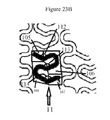


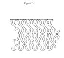
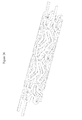


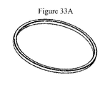


Classifications
-
- A—HUMAN NECESSITIES
- A61—MEDICAL OR VETERINARY SCIENCE; HYGIENE
- A61F—FILTERS IMPLANTABLE INTO BLOOD VESSELS; PROSTHESES; DEVICES PROVIDING PATENCY TO, OR PREVENTING COLLAPSING OF, TUBULAR STRUCTURES OF THE BODY, e.g. STENTS; ORTHOPAEDIC, NURSING OR CONTRACEPTIVE DEVICES; FOMENTATION; TREATMENT OR PROTECTION OF EYES OR EARS; BANDAGES, DRESSINGS OR ABSORBENT PADS; FIRST-AID KITS
- A61F2/00—Filters implantable into blood vessels; Prostheses, i.e. artificial substitutes or replacements for parts of the body; Appliances for connecting them with the body; Devices providing patency to, or preventing collapsing of, tubular structures of the body, e.g. stents
- A61F2/82—Devices providing patency to, or preventing collapsing of, tubular structures of the body, e.g. stents
- A61F2/86—Stents in a form characterised by the wire-like elements; Stents in the form characterised by a net-like or mesh-like structure
- A61F2/90—Stents in a form characterised by the wire-like elements; Stents in the form characterised by a net-like or mesh-like structure characterised by a net-like or mesh-like structure
- A61F2/91—Stents in a form characterised by the wire-like elements; Stents in the form characterised by a net-like or mesh-like structure characterised by a net-like or mesh-like structure made from perforated sheet material or tubes, e.g. perforated by laser cuts or etched holes
- A61F2/915—Stents in a form characterised by the wire-like elements; Stents in the form characterised by a net-like or mesh-like structure characterised by a net-like or mesh-like structure made from perforated sheet material or tubes, e.g. perforated by laser cuts or etched holes with bands having a meander structure, adjacent bands being connected to each other
-
- A—HUMAN NECESSITIES
- A61—MEDICAL OR VETERINARY SCIENCE; HYGIENE
- A61F—FILTERS IMPLANTABLE INTO BLOOD VESSELS; PROSTHESES; DEVICES PROVIDING PATENCY TO, OR PREVENTING COLLAPSING OF, TUBULAR STRUCTURES OF THE BODY, e.g. STENTS; ORTHOPAEDIC, NURSING OR CONTRACEPTIVE DEVICES; FOMENTATION; TREATMENT OR PROTECTION OF EYES OR EARS; BANDAGES, DRESSINGS OR ABSORBENT PADS; FIRST-AID KITS
- A61F2/00—Filters implantable into blood vessels; Prostheses, i.e. artificial substitutes or replacements for parts of the body; Appliances for connecting them with the body; Devices providing patency to, or preventing collapsing of, tubular structures of the body, e.g. stents
- A61F2/82—Devices providing patency to, or preventing collapsing of, tubular structures of the body, e.g. stents
- A61F2/86—Stents in a form characterised by the wire-like elements; Stents in the form characterised by a net-like or mesh-like structure
- A61F2/89—Stents in a form characterised by the wire-like elements; Stents in the form characterised by a net-like or mesh-like structure the wire-like elements comprising two or more adjacent rings flexibly connected by separate members
-
- A—HUMAN NECESSITIES
- A61—MEDICAL OR VETERINARY SCIENCE; HYGIENE
- A61F—FILTERS IMPLANTABLE INTO BLOOD VESSELS; PROSTHESES; DEVICES PROVIDING PATENCY TO, OR PREVENTING COLLAPSING OF, TUBULAR STRUCTURES OF THE BODY, e.g. STENTS; ORTHOPAEDIC, NURSING OR CONTRACEPTIVE DEVICES; FOMENTATION; TREATMENT OR PROTECTION OF EYES OR EARS; BANDAGES, DRESSINGS OR ABSORBENT PADS; FIRST-AID KITS
- A61F2/00—Filters implantable into blood vessels; Prostheses, i.e. artificial substitutes or replacements for parts of the body; Appliances for connecting them with the body; Devices providing patency to, or preventing collapsing of, tubular structures of the body, e.g. stents
- A61F2/82—Devices providing patency to, or preventing collapsing of, tubular structures of the body, e.g. stents
- A61F2/86—Stents in a form characterised by the wire-like elements; Stents in the form characterised by a net-like or mesh-like structure
- A61F2/90—Stents in a form characterised by the wire-like elements; Stents in the form characterised by a net-like or mesh-like structure characterised by a net-like or mesh-like structure
- A61F2/91—Stents in a form characterised by the wire-like elements; Stents in the form characterised by a net-like or mesh-like structure characterised by a net-like or mesh-like structure made from perforated sheet material or tubes, e.g. perforated by laser cuts or etched holes
- A61F2/915—Stents in a form characterised by the wire-like elements; Stents in the form characterised by a net-like or mesh-like structure characterised by a net-like or mesh-like structure made from perforated sheet material or tubes, e.g. perforated by laser cuts or etched holes with bands having a meander structure, adjacent bands being connected to each other
- A61F2002/91525—Stents in a form characterised by the wire-like elements; Stents in the form characterised by a net-like or mesh-like structure characterised by a net-like or mesh-like structure made from perforated sheet material or tubes, e.g. perforated by laser cuts or etched holes with bands having a meander structure, adjacent bands being connected to each other within the whole structure different bands showing different meander characteristics, e.g. frequency or amplitude
-
- A—HUMAN NECESSITIES
- A61—MEDICAL OR VETERINARY SCIENCE; HYGIENE
- A61F—FILTERS IMPLANTABLE INTO BLOOD VESSELS; PROSTHESES; DEVICES PROVIDING PATENCY TO, OR PREVENTING COLLAPSING OF, TUBULAR STRUCTURES OF THE BODY, e.g. STENTS; ORTHOPAEDIC, NURSING OR CONTRACEPTIVE DEVICES; FOMENTATION; TREATMENT OR PROTECTION OF EYES OR EARS; BANDAGES, DRESSINGS OR ABSORBENT PADS; FIRST-AID KITS
- A61F2/00—Filters implantable into blood vessels; Prostheses, i.e. artificial substitutes or replacements for parts of the body; Appliances for connecting them with the body; Devices providing patency to, or preventing collapsing of, tubular structures of the body, e.g. stents
- A61F2/82—Devices providing patency to, or preventing collapsing of, tubular structures of the body, e.g. stents
- A61F2/86—Stents in a form characterised by the wire-like elements; Stents in the form characterised by a net-like or mesh-like structure
- A61F2/90—Stents in a form characterised by the wire-like elements; Stents in the form characterised by a net-like or mesh-like structure characterised by a net-like or mesh-like structure
- A61F2/91—Stents in a form characterised by the wire-like elements; Stents in the form characterised by a net-like or mesh-like structure characterised by a net-like or mesh-like structure made from perforated sheet material or tubes, e.g. perforated by laser cuts or etched holes
- A61F2/915—Stents in a form characterised by the wire-like elements; Stents in the form characterised by a net-like or mesh-like structure characterised by a net-like or mesh-like structure made from perforated sheet material or tubes, e.g. perforated by laser cuts or etched holes with bands having a meander structure, adjacent bands being connected to each other
- A61F2002/9155—Adjacent bands being connected to each other
- A61F2002/91558—Adjacent bands being connected to each other connected peak to peak
-
- A—HUMAN NECESSITIES
- A61—MEDICAL OR VETERINARY SCIENCE; HYGIENE
- A61F—FILTERS IMPLANTABLE INTO BLOOD VESSELS; PROSTHESES; DEVICES PROVIDING PATENCY TO, OR PREVENTING COLLAPSING OF, TUBULAR STRUCTURES OF THE BODY, e.g. STENTS; ORTHOPAEDIC, NURSING OR CONTRACEPTIVE DEVICES; FOMENTATION; TREATMENT OR PROTECTION OF EYES OR EARS; BANDAGES, DRESSINGS OR ABSORBENT PADS; FIRST-AID KITS
- A61F2210/00—Particular material properties of prostheses classified in groups A61F2/00 - A61F2/26 or A61F2/82 or A61F9/00 or A61F11/00 or subgroups thereof
- A61F2210/0004—Particular material properties of prostheses classified in groups A61F2/00 - A61F2/26 or A61F2/82 or A61F9/00 or A61F11/00 or subgroups thereof bioabsorbable
-
- A—HUMAN NECESSITIES
- A61—MEDICAL OR VETERINARY SCIENCE; HYGIENE
- A61F—FILTERS IMPLANTABLE INTO BLOOD VESSELS; PROSTHESES; DEVICES PROVIDING PATENCY TO, OR PREVENTING COLLAPSING OF, TUBULAR STRUCTURES OF THE BODY, e.g. STENTS; ORTHOPAEDIC, NURSING OR CONTRACEPTIVE DEVICES; FOMENTATION; TREATMENT OR PROTECTION OF EYES OR EARS; BANDAGES, DRESSINGS OR ABSORBENT PADS; FIRST-AID KITS
- A61F2230/00—Geometry of prostheses classified in groups A61F2/00 - A61F2/26 or A61F2/82 or A61F9/00 or A61F11/00 or subgroups thereof
- A61F2230/0002—Two-dimensional shapes, e.g. cross-sections
- A61F2230/0004—Rounded shapes, e.g. with rounded corners
- A61F2230/0013—Horseshoe-shaped, e.g. crescent-shaped, C-shaped, U-shaped
-
- A—HUMAN NECESSITIES
- A61—MEDICAL OR VETERINARY SCIENCE; HYGIENE
- A61F—FILTERS IMPLANTABLE INTO BLOOD VESSELS; PROSTHESES; DEVICES PROVIDING PATENCY TO, OR PREVENTING COLLAPSING OF, TUBULAR STRUCTURES OF THE BODY, e.g. STENTS; ORTHOPAEDIC, NURSING OR CONTRACEPTIVE DEVICES; FOMENTATION; TREATMENT OR PROTECTION OF EYES OR EARS; BANDAGES, DRESSINGS OR ABSORBENT PADS; FIRST-AID KITS
- A61F2250/00—Special features of prostheses classified in groups A61F2/00 - A61F2/26 or A61F2/82 or A61F9/00 or A61F11/00 or subgroups thereof
- A61F2250/0014—Special features of prostheses classified in groups A61F2/00 - A61F2/26 or A61F2/82 or A61F9/00 or A61F11/00 or subgroups thereof having different values of a given property or geometrical feature, e.g. mechanical property or material property, at different locations within the same prosthesis
- A61F2250/0039—Special features of prostheses classified in groups A61F2/00 - A61F2/26 or A61F2/82 or A61F9/00 or A61F11/00 or subgroups thereof having different values of a given property or geometrical feature, e.g. mechanical property or material property, at different locations within the same prosthesis differing in diameter
Landscapes
- Health & Medical Sciences (AREA)
- Engineering & Computer Science (AREA)
- Biomedical Technology (AREA)
- Life Sciences & Earth Sciences (AREA)
- General Health & Medical Sciences (AREA)
- Transplantation (AREA)
- Heart & Thoracic Surgery (AREA)
- Vascular Medicine (AREA)
- Cardiology (AREA)
- Animal Behavior & Ethology (AREA)
- Oral & Maxillofacial Surgery (AREA)
- Public Health (AREA)
- Veterinary Medicine (AREA)
- Physics & Mathematics (AREA)
- Optics & Photonics (AREA)
- Media Introduction/Drainage Providing Device (AREA)
- Prostheses (AREA)
Abstract
【解決手段】 本発明は、高い柔軟性および径方向強度を呈する幾何学的設計を伴った拡張型ステントに関する。本発明のステントは、複数の拡張可能な第1および第2の周囲形成要素を有し、略円筒形状に形成された本体を有する。当該ステントが拡張されると、前記第2の周囲形成要素はリング状またはフープ状の構造を形成する。特定の実施形態では、前記本体に、複数の拡張可能な第1、第2、および第3の周囲形成要素が含まれ、前記第2および第3の周囲形成要素の双方は、拡張時、リング状またはフープ状の構造を形成する。前記ステントは、さらに、前記本体のキャップとなる端部ゾーン、すなわち前記本体の両端部に位置する2つの端部ゾーンを有することができる。
【選択図】 図1The present invention relates to an expandable stent with a geometric design that exhibits high flexibility and radial strength. The stent of the present invention has a plurality of expandable first and second perimeter forming elements and a body formed in a generally cylindrical shape. When the stent is expanded, the second perimeter forming element forms a ring-like or hoop-like structure. In certain embodiments, the body includes a plurality of expandable first, second, and third perimeter forming elements, both of the second and third perimeter forming elements being rings when expanded. Form a hoop-like or hoop-like structure. The stent may further have end zones that serve as caps of the body, i.e., two end zones located at both ends of the body.
[Selection] Figure 1
Description
本願は、2011年1月27日付で出願された米国仮特許出願第61/436,793号に対して優先権を主張するものである。 This application claims priority to US Provisional Patent Application No. 61 / 436,793, filed Jan. 27, 2011.
本発明は、ステントに関する。特に、本発明は、高い径方向強度および柔軟性を呈するステントの幾何学的設計に関する。 The present invention relates to a stent. In particular, the present invention relates to a geometric design of a stent that exhibits high radial strength and flexibility.
ステントは、病変のある管部分の内側に留置されてその管壁を支える骨組みである。血管形成術中、ステントは、血管を修復し、再形成するため使用される。動脈病変部にステントを留置すると、当該動脈の弾性収縮および閉塞が防止される。また、ステントは、中膜の局所的な動脈解離を防ぐ。生理学的にいうと、ステントは、任意空間の管腔、例えば動脈、静脈、胆管、尿路、消化管、気管気管支樹、中脳水道、泌尿生殖器系の内側に留置できる。ステントは、ヒト以外の動物、例えば霊長類、馬、牛、および羊の管腔の内側に留置するもできる。 A stent is a framework that is placed inside a lesioned tube section to support the tube wall. During angioplasty, stents are used to repair and remodel blood vessels. When a stent is placed in an arterial lesion, elastic contraction and occlusion of the artery are prevented. Stents also prevent local arterial dissection of the media. Physiologically speaking, a stent can be placed inside a lumen of any space, such as an artery, vein, bile duct, urinary tract, gastrointestinal tract, tracheobronchial tree, midbrain aqueduct, urogenital system. Stents can also be placed inside the lumens of non-human animals such as primates, horses, cows, and sheep.
一般に、ステントには自己拡張型およびバルーン拡張型の2タイプがある。自己拡張型ステントは、一度リリースすると自動的に拡張し、展開・拡張された状態になる。自己拡張型ステントは、圧縮した状態で病変部、例えば狭窄領域に挿入することにより管内に留置される。ステントの圧縮またはクリンプは、クリンプ装置を使って達成される(2009年4月http://www.machinesolutions.org/stent_crimping.htmを参照)。また、ステントは、管病変部の内径より小さい外径を有するチューブを使っても圧縮できる。圧縮力を取り除き、または温度を上げると、ステントは拡張して管の内腔を埋める。チューブ内に閉じ込めていたステントをチューブ外にリリースすると、ステントは拡張して元の形状に戻り、その過程で管の内壁に抗して強固に固定される。 In general, there are two types of stents: self-expandable and balloon expandable. A self-expanding stent automatically expands once released and is in a deployed and expanded state. The self-expanding stent is placed in a tube by being inserted into a lesioned part, for example, a stenosis region in a compressed state. Stent compression or crimping is accomplished using a crimping apparatus (see April 2009 http://www.machinesolutions.org/sent_crimping.htm). The stent can also be compressed using a tube having an outer diameter smaller than the inner diameter of the vascular lesion. When the compressive force is removed or the temperature is increased, the stent expands to fill the lumen of the tube. When the stent confined in the tube is released out of the tube, the stent expands and returns to its original shape, and is firmly fixed against the inner wall of the tube in the process.
バルーン拡張型ステントは、膨張可能なバルーンカテーテルを使って拡張される。バルーン拡張型ステントは、未拡張またはクリンプした状態のステントをカテーテルのバルーン部分に装着することにより留置できる。カテーテルは、クリンプしたステントを上から装着した後、管壁を穿刺して設けた孔口に挿通され、修復の必要な管部分に位置付けられるまで前記管内を通される。次に、前記ステントは、前記管の内壁に抗して前記バルーンカテーテルを膨張させることにより拡張される。具体的にいうと、ステントは、その口径が広がり当該ステントが拡張するようバルーンを膨張させることで可塑的に変形される。 Balloon expandable stents are expanded using an inflatable balloon catheter. The balloon expandable stent can be placed by attaching an unexpanded or crimped stent to the balloon portion of the catheter. After the crimped stent is mounted from above, the catheter is inserted into a hole provided by puncturing the tube wall and passed through the tube until it is positioned at a tube portion that needs to be repaired. The stent is then expanded by inflating the balloon catheter against the inner wall of the tube. Specifically, the stent is plastically deformed by inflating the balloon so that the diameter of the stent increases and the stent expands.
多くのステントには、共通する機能的な制限がある。その問題として、例えばクリンプ状態および展開状態のステントの比剛性と、柔軟性の制約とがあり、これらのため細い管内への送達および留置が困難になっている。本発明は、ステントに幾何学的設計を提供して、高い柔軟性および著しい径方向強度の双方をもたらす。また、このステント設計により、蛇行した管構造を有する小口径管への挿入が可能になる。 Many stents have common functional limitations. The problems include, for example, the specific stiffness and flexibility limitations of the crimped and deployed stents, which make delivery and placement in narrow tubes difficult. The present invention provides a geometric design for the stent, providing both high flexibility and significant radial strength. This stent design also allows insertion into a small diameter tube having a serpentine tube structure.
本発明は、少なくとも1つの生体吸収性ポリマーを有するステントであって、複数の第1の周囲形成要素(circumferential element)および複数の第2の周囲形成要素を有するステントを提供する。前記第1の周囲形成要素および前記第2の周囲形成要素は、交互に繰り返すパターンで構成される。隣接しあう第1および第2の周囲形成要素は、少なくとも1つの連結要素により連結される。前記第1の周囲形成要素の周囲は、前記第2の周囲形成要素の周囲より長い。前記第1の周囲形成要素は、複数の波状形状を有する。前記第2の周囲形成要素は、拡張時にフープ状の構造を有する。前記ステントは、クリンプでき、または拡張させることができる。 The present invention provides a stent having at least one bioabsorbable polymer having a plurality of first circumferential elements and a plurality of second surrounding elements. The first surrounding forming element and the second surrounding forming element are configured in an alternating pattern. Adjacent first and second surrounding forming elements are connected by at least one connecting element. The circumference of the first surrounding element is longer than the circumference of the second surrounding element. The first surrounding forming element has a plurality of wavy shapes. The second surrounding forming element has a hoop-like structure when expanded. The stent can be crimped or expanded.
本発明は、さらに、少なくとも1つの生体吸収性ポリマーを有するステントであって、複数の第1の周囲形成要素、複数の第2の周囲形成要素、および複数の第3の周囲形成要素を有するステントを提供する。前記第1、第2、および第3の周囲形成要素は、少なくとも3回繰り返される群を形成する。隣接しあう第1および第2の周囲形成要素は、少なくとも1つの連結要素により連結される。隣接しあう第1および第3の周囲形成要素は、少なくとも1つの連結要素により連結される。隣接しあう第2および第3の周囲形成要素は、少なくとも1つの連結要素により連結される。前記第1の周囲形成要素の周囲は、前記第2および第3の周囲形成要素の周囲より長い。前記第1の周囲形成要素は、複数の波状形状を有する。前記第2の周囲形成要素は、拡張時にフープ状の構造を有する。前記第3の周囲形成要素は、拡張時にフープ状の構造を有する。前記ステントは、クリンプでき、または拡張させることができる。 The present invention further includes a stent having at least one bioabsorbable polymer having a plurality of first perimeter forming elements, a plurality of second perimeter forming elements, and a plurality of third perimeter forming elements. I will provide a. The first, second, and third surrounding forming elements form a group that is repeated at least three times. Adjacent first and second surrounding forming elements are connected by at least one connecting element. Adjacent first and third surrounding forming elements are connected by at least one connecting element. Adjacent second and third surrounding forming elements are connected by at least one connecting element. The circumference of the first surrounding forming element is longer than the circumference of the second and third surrounding forming elements. The first surrounding forming element has a plurality of wavy shapes. The second surrounding forming element has a hoop-like structure when expanded. The third surrounding forming element has a hoop-like structure when expanded. The stent can be crimped or expanded.
前記第1の周囲形成要素内の少なくとも1つの波状形状は、少なくとも1つの角度を成す少なくとも2つのセグメントを有し、前記少なくとも1つの角度は、前記ステントが未拡張のとき、約30°〜約180°または約60°〜約150°の範囲にできる。前記セグメントは、長さが等しく、または等しくなくてもよい。前記セグメントは、直線状でも曲線状でもよい。 The at least one undulating shape in the first surrounding forming element has at least two segments forming at least one angle, the at least one angle being between about 30 ° and about when the stent is unexpanded. It can be 180 ° or in the range of about 60 ° to about 150 °. The segments may or may not be equal in length. The segment may be linear or curved.
前記第1の周囲形成要素は、複数の第1の波状形状および複数の第2の波状形状を有することができる。前記第1の周囲形成要素は、複数の第1の波状形状、複数の第2の波状形状、および複数の第3の波状形状を有することができる。 The first surrounding forming element can have a plurality of first wavy shapes and a plurality of second wavy shapes. The first surrounding forming element can have a plurality of first wavy shapes, a plurality of second wavy shapes, and a plurality of third wavy shapes.
隣接しあう第1および第2の周囲形成要素は、2つまたは3つの連結要素により連結される。隣接しあう第1の周囲形成要素および第2の周囲形成要素は、少なくとも1つの第1の支柱により連結してもよく、または直接連結することができる。前記第2の周囲形成要素は、クリンプ時に正弦波パターンであってもよい。前記第2の周囲形成要素は、少なくとも1つの凹部、例えばノッチを有する(notched)構造をさらに有することができる。 Adjacent first and second surrounding forming elements are connected by two or three connecting elements. The adjacent first and second surrounding elements may be connected by at least one first strut, or may be directly connected. The second surrounding forming element may be a sinusoidal pattern when crimped. The second perimeter forming element may further comprise a structure having at least one recess, for example a notched.
前記ステントは、さらに、前記ステントの一端部または両端部に位置少なくとも1つの端部ゾーンを有することができ、その端部ゾーンは、複数の円筒形要素を有する。前記第2の周囲形成要素は、未拡張時、正弦波パターンであってもよい。前記端部ゾーンは、少なくとも1つの第2の支柱により前記第1の周囲形成要素に取り付けることができる。前記端部ゾーンは、前記第1の周囲形成要素に直接取り付けることができる。前記端部ゾーンは、少なくとも1つの放射線不透過性マーカーをさらに有してもよい。 The stent may further have at least one end zone located at one or both ends of the stent, the end zone having a plurality of cylindrical elements. The second surrounding forming element may be a sine wave pattern when unexpanded. The end zone can be attached to the first surrounding forming element by at least one second strut. The end zone can be directly attached to the first surrounding forming element. The end zone may further comprise at least one radiopaque marker.
隣接しあう第1および第2の周囲形成要素は、2つの連結要素により連結することができる。隣接しあう第1および第3の周囲形成要素は、2つの連結要素により連結することができる。隣接しあう第2および第3の周囲形成要素は、6つの連結要素により連結することができる。隣接しあう第2の周囲形成要素および第3の周囲形成要素は、少なくとも1つの第1の支柱により連結することができる。隣接しあう第1の周囲形成要素および第2の周囲形成要素は、直接連結することができる。隣接しあう第1の周囲形成要素および第3の周囲形成要素は、直接連結することができる。 Adjacent first and second surrounding forming elements can be connected by two connecting elements. Adjacent first and third surrounding forming elements can be connected by two connecting elements. Adjacent second and third surrounding forming elements can be connected by six connecting elements. The adjacent second and third surrounding elements can be connected by at least one first strut. The adjacent first and second surrounding elements can be directly connected. The adjacent first and third surrounding elements can be directly connected.
前記第2の周囲形成要素は、未拡張時、正弦波パターンであってもよい。前記第3の周囲形成要素は、未拡張時、正弦波パターンであってもよい。 The second surrounding forming element may be a sine wave pattern when unexpanded. The third surrounding forming element may be a sine wave pattern when not expanded.
本発明は、高い柔軟性および径方向強度を有する幾何学的設計を伴った拡張型ステントに関する。本発明のステントは、複数の拡張可能な第1および第2の周囲形成要素を有し、略円筒形状に形成された本体を有する。当該ステントが拡張されると、前記第2の周囲形成要素はリング状またはフープ状の構造を形成する。そのため、拡張した当該ステントは、単一リングを重ねたものが、拡張した第1の周囲形成要素により分離された構造を有する。特定の実施形態では、前記本体に、複数の拡張可能な第1、第2、および第3の周囲形成要素が含まれ、前記第2および第3の周囲形成要素の双方は、拡張時、リング状またはフープ状の構造を形成する。そのため、拡張した当該ステントは、二重のリングを重ねたものが、拡張した第1の周囲形成要素により分離された構造を有する。特定の実施形態において、ステントは、複数の三重リングが、拡張した第1の周囲形成要素により分離された構造を有することができる。前記ステントは、さらに、前記本体のキャップとなる端部ゾーン、すなわち前記本体の両端に配置された2つの端部ゾーンを有することができる。 The present invention relates to an expandable stent with a geometric design having high flexibility and radial strength. The stent of the present invention has a plurality of expandable first and second perimeter forming elements and a body formed in a generally cylindrical shape. When the stent is expanded, the second perimeter forming element forms a ring-like or hoop-like structure. Thus, the expanded stent has a structure in which a single ring is separated by an expanded first surrounding forming element. In certain embodiments, the body includes a plurality of expandable first, second, and third perimeter forming elements, both of the second and third perimeter forming elements being rings when expanded. Form a hoop-like or hoop-like structure. Thus, the expanded stent has a structure in which the double rings are separated by the expanded first surrounding forming element. In certain embodiments, the stent can have a structure in which a plurality of triple rings are separated by an expanded first surrounding forming element. The stent may further have end zones that serve as caps of the body, i.e. two end zones located at both ends of the body.
特定の実施形態において、前記ステントの本体は、交互に繰り返すパターンで構成された複数の第1および第2の周囲形成要素を含んでよい。前記周囲形成要素は、前記本体の筒軸と共線的な筒軸を有する。前記周囲形成要素は、実質的に波状の形態であり、交互に繰り返す一連の谷および山を提供する。また、それらの周囲形成要素は、他の形態、例えば鋸歯状のパターンをとることもできる。放射状に拡張する力がステントにかかると、前記周囲形成要素は放射状に拡張し、周囲に沿って伸長する。逆に、圧縮力が外からステントにかかると、前記周囲形成要素は放射状に収縮し、周囲に沿って短くなる。前記第1の周囲形成要素の周囲は、前記第2の周囲形成要素の周囲より長くてもよい。あるいは、前記第1の周囲形成要素の周囲は、前記第2の周囲形成要素の周囲と比べて短くても、等しくてもよい。前記第1および第2の周囲形成要素は、互いに異なっても実質的に同一であってもよい。 In certain embodiments, the body of the stent may include a plurality of first and second perimeter forming elements configured in an alternating repeating pattern. The surrounding forming element has a cylindrical axis that is collinear with the cylindrical axis of the main body. The surrounding forming elements are substantially wavy in shape and provide a series of alternating valleys and peaks. The surrounding forming elements can also take other forms, for example a sawtooth pattern. When a radially expanding force is applied to the stent, the perimeter forming element expands radially and extends along the periphery. Conversely, when a compressive force is applied to the stent from the outside, the surrounding forming element contracts radially and shortens along the periphery. The circumference of the first surrounding element may be longer than the circumference of the second surrounding element. Alternatively, the periphery of the first surrounding forming element may be shorter or the same as the surrounding of the second surrounding forming element. The first and second surrounding forming elements may be different from each other or substantially the same.
第1の周囲形成要素は、複数の蛇行した要素(meandering elements)または波状形状(undulations)を有することができる。波状形状は、様式化されたS、Z、L(l)、M、N、Wの形状をとることができる。また、波状形状は、他のいかなる適切な構成でもよい。前記波状形状は、一体的に接合してパターンを形成できる。前記ステントがクリンプ(crimp)されているとき、そのパターンは繰り返しても繰り返さなくてもよい。1つの周囲形成要素内の波状形状は、同一であっても異なってもよい。例えば、第1の周囲形成要素は、複数の第1の波状形状および複数の第2の波状形状を有することができる。1つの周囲形成要素は、複数の第1の波状形状、複数の第2の波状形状、および複数の第3の波状形状を有することもできる。本発明では、1つの周囲形成要素内に、さらに多くのタイプの波状形状を含めてもよい。前記波状形状は、一体的に接合して交互に繰り返すパターンまたは他の繰り返しパターンを形成できる。前記繰り返しパターンの非限定的な例としては、正弦波形、方形波形、矩形波形、三角波形、スパイク波形、台形波形、およびのこぎり波形などがある。また、周囲形成要素の波状形状は、一体的に接合して非繰り返しパターンを形成できる。本発明に使用できるパターンとしては、径方向の拡張力がステントにかかったとき前記周囲形成要素が拡張でき、外から圧縮力がかかったときは折り畳まれるようにする任意の適切なパターンなどがある。 The first surrounding forming element can have a plurality of meandering elements or undulations. The wavy shape can take the form of stylized S, Z, L (l), M, N, W. The wavy shape may have any other suitable configuration. The wavy shapes can be joined together to form a pattern. When the stent is crimped, the pattern may or may not repeat. The wavy shapes within one surrounding forming element may be the same or different. For example, the first surrounding forming element can have a plurality of first wavy shapes and a plurality of second wavy shapes. One surrounding forming element can also have a plurality of first wavy shapes, a plurality of second wavy shapes, and a plurality of third wavy shapes. In the present invention, more types of corrugated shapes may be included within one surrounding forming element. The wavy shape can be joined together to form an alternating pattern or other repeating pattern. Non-limiting examples of the repetitive pattern include a sine waveform, a square waveform, a rectangular waveform, a triangular waveform, a spike waveform, a trapezoidal waveform, and a sawtooth waveform. Further, the wavy shape of the surrounding forming elements can be integrally joined to form a non-repeating pattern. Patterns that can be used in the present invention include any suitable pattern that allows the surrounding forming element to expand when a radial expansion force is applied to the stent and to fold when a compression force is applied from the outside. .
波状形状は、少なくとも1つの振幅を有することができる。本明細書において、波状形状の振幅とは、その波状形状の谷(または谷の1つ)と山(または山の1つ)との間の軸距離で定義される。放射状に拡張する力がステントにかかると、前記波状形状の振幅は収縮する。逆に、圧縮力が外からステントにかかると、前記波状形状の振幅は大きくなる。周囲形成要素が1より多くの波状形状を含む場合、それら波状形状の振幅は同一であっても異なってもよい。第2の周囲形成要素では、各山を各谷から同様な距離で軸方向に離間させて、当該第2の周囲形成要素の波状形状が同一の振幅を有するようにできる。 The wavy shape can have at least one amplitude. In the present specification, the amplitude of the wavy shape is defined by the axial distance between the trough (or one of the troughs) and the mountain (or one of the peaks) of the wavy shape. As the radially expanding force is applied to the stent, the wavy amplitude contracts. Conversely, when a compressive force is applied to the stent from the outside, the amplitude of the wavy shape increases. If the surrounding forming elements contain more than one wavy shape, the amplitudes of the wavy shapes may be the same or different. In the second surrounding forming element, each peak can be axially spaced from each valley by a similar distance so that the wavy shape of the second surrounding forming element has the same amplitude.
あるいは、前記第2の周囲形成要素の波状形状の振幅は、場合により異なる。前記第1の周囲形成要素の波状形状の振幅は、前記第2の周囲形成要素の波状形状の振幅と比べ、大きくても、等しくても、小さくてもよい。 Alternatively, the amplitude of the wavy shape of the second surrounding forming element varies depending on the case. The amplitude of the wavy shape of the first surrounding forming element may be larger, equal or smaller than the amplitude of the wavy shape of the second surrounding forming element.
第1の周囲形成要素は、同一の波状形状を含んでも、異なる波状形状を含んでもよい。例えば、前記波状形状が同一でない場合は、交互に繰り返すパターンで構成された複数の第1の波状形状および複数の第2の波状形状を第1の周囲形成要素に含めることができる。また、複数の第1の波状形状、複数の第2の波状形状、および複数の第3の波状形状を第1の周囲形成要素に含めることもできる。第1の周囲形成要素内の波状形状タイプの数は、1〜20、1〜15、2〜10、または2〜6の範囲にできる。 The first surrounding forming elements may include the same wavy shape or different wavy shapes. For example, if the wavy shapes are not the same, a plurality of first wavy shapes and a plurality of second wavy shapes configured in an alternating pattern can be included in the first surrounding forming element. A plurality of first wavy shapes, a plurality of second wavy shapes, and a plurality of third wavy shapes can also be included in the first surrounding forming element. The number of corrugated shape types in the first surrounding forming element can range from 1-20, 1-15, 2-10, or 2-6.
第2の周囲形成要素は、繰り返しまたは非繰り返しパターンを形成する複数の波状形状を含んでよい。例えばクリンプ時、前記第2の周囲形成要素は、正弦波パターンにできる。上述のように、前記第2の周囲形成要素は、いかなる適切な構成もとれる。一実施形態において、前記第2の周囲形成要素は、拡張時にリング状またはフープ状の構造を有することができ、そのリングまたはフープは実質的に同じ平面内に位置する。本明細書における用語「平面」は、ステントの筒軸と実質的に直交する理論的な2次元単位と定義される。第2の周囲形成要素は、同一の波状形状を含んでも、異なる波状形状を含んでもよい。例えば、前記波状形状が同一でない場合は、複数の第1の波状形状および複数の第2の波状形状があってよい。 The second surrounding forming element may include a plurality of wavy shapes that form a repeating or non-repeating pattern. For example, when crimping, the second surrounding forming element can be a sinusoidal pattern. As described above, the second perimeter forming element can be in any suitable configuration. In one embodiment, the second perimeter forming element can have a ring-like or hoop-like structure when expanded, and the ring or hoop is located in substantially the same plane. As used herein, the term “plane” is defined as a theoretical two-dimensional unit that is substantially orthogonal to the tube axis of the stent. The second surrounding forming elements may include the same wavy shape or different wavy shapes. For example, if the wavy shapes are not the same, there may be a plurality of first wavy shapes and a plurality of second wavy shapes.
1つの波状形状は、1つのセグメント、または少なくとも2つの隣接しあうセグメントが角度を成す少なくとも2つのセグメントを有することができる。前記セグメントは、直線状でも曲線状でもよい。セグメントが曲線状のとき、その曲率は場合により異なる。セグメントは、凹状でも凸状でもよい。セグメントは、一体的に接合された直線状の部分のみ、または一体的に接合された曲線状の部分のみを含んでよい。あるいは、セグメントは、一体的に接合された直線状の部分および曲線状の部分の双方を含んでよい。直線状の部分は、ステントの筒軸に平行であっても、またはステントの筒軸に対し約0°〜約60°または約0°〜約45°範囲の角度を成してもよい。前記セグメントは、その長手方向に沿って選択された点に配置された屈曲を少なくとも1つ有することができる。例えば、1つのセグメントは、様式化されたn、C、U、Vなどの形状をとることができる。また、1つのセグメントはループ形状にでき、そのループを円形または半円形にできる。前記セグメントは、本質的にいかなる適切な構成にもできる。 A wavy shape can have one segment or at least two segments that are angled by at least two adjacent segments. The segment may be linear or curved. When a segment is curved, its curvature varies from case to case. The segment may be concave or convex. A segment may include only linear portions joined together, or only curved portions joined together. Alternatively, the segment may include both straight and curved portions joined together. The straight portion may be parallel to the stent tube axis or may form an angle in the range of about 0 ° to about 60 ° or about 0 ° to about 45 ° relative to the stent tube axis. The segment may have at least one bend disposed at a selected point along its length. For example, a segment can take the form of stylized n, C, U, V, etc. Also, one segment can be a loop shape, and the loop can be circular or semi-circular. The segments can be essentially any suitable configuration.
少なくとも2つのセグメントは、一体的に接合して波状形状の若しくは蛇行した要素を形成できる。1つの波状形状には、0〜N−1個の角度を成して隣接しあう0〜N−1対のセグメントを伴ったN個のセグメントを含めることができる(Nは任意の正整数、すなわち1、2、3、4、5など)。例えば、第1の周囲形成要素において、波状形状は、対向しあって角度を成した2つのセグメントを有することができる。1つの波状形状には、0、1、または2つの角度を成す3つのセグメントを含めることができる。1つの波状形状には、0、1、2、または3つの角度を成す4つのセグメントを含めることができる。波状形状の数と、隣接しあうセグメントが成す角度の数とがそれより多い場合も、本発明に包含される。1つの波状形状内で、前記角度は一定であっても異なってもよい。一実施形態の第1の周囲形成要素では、2つの対向しあう角度を成したセグメントが各波状形状にあってよく、それらのセグメントは各波状形状内で角度を成す。第1の周囲形成要素内で、前記セグメントが成す角度は、波状形状ごとに一定であっても異なってもよい。前記第1の周囲形成要素内の1つの波状形状におけるセグメントの長さ、幅、および厚さは、等しくても等しくなくてもよい。特定の実施形態では、1つの周囲形成要素がセグメントのみ有する。
The at least two segments can be joined together to form a wavy or serpentine element. A wavy shape can include N segments with 0-N-1 pairs of segments adjacent to each other at 0-N-1 angles, where N is any positive integer,
また、隣接しあう波状形状が角度を成すこともできる。第1の周囲形成要素において、隣接しあう波状形状が成す角度は、一定であっても異なってもよい。波状形状内で隣接しあうセグメントが成す角度は、隣接しあう波状形状が成す角度と比べ、大きくても、等しくても、小さくてもよい。前記ステントがクリンプされている場合、前記角度は、約30°〜約180°、約45°〜約160°、約60°〜約150°、または約90°〜約120°の範囲にできる。 Adjacent wavy shapes can also form an angle. In the first surrounding forming element, the angle formed by the adjacent wavy shapes may be constant or different. The angle formed by the adjacent segments in the wavy shape may be larger, equal, or smaller than the angle formed by the adjacent wavy shapes. When the stent is crimped, the angle can range from about 30 ° to about 180 °, from about 45 ° to about 160 °, from about 60 ° to about 150 °, or from about 90 ° to about 120 °.
特定の実施形態において、少なくとも2つの隣接しあうセグメントは、第1の角度を成し、隣接しあう少なくとも2つの波状形状は、第2の角度を成す。 In certain embodiments, at least two adjacent segments form a first angle and at least two adjacent wavy shapes form a second angle.
前記周囲形成要素のフィラメント幅は、約0.05mm〜約2.5mm、約0.05mm〜約1.3mm、約1mm〜約2mm、約1.5mm〜約2.5mm、約0.05mm〜約1.5mm、約0.05mm〜約1mm、約0.05mm〜約0.5mm、約0.05mm〜約0.3mm、約0.08mm〜約0.25mm、約0.1mm〜約0.25mm、約0.12mm〜約0.2mm、約0.18mm〜約0.20mm、または約0.13mmの範囲にできる。 The filament width of the surrounding forming element is about 0.05 mm to about 2.5 mm, about 0.05 mm to about 1.3 mm, about 1 mm to about 2 mm, about 1.5 mm to about 2.5 mm, about 0.05 mm to About 1.5 mm, about 0.05 mm to about 1 mm, about 0.05 mm to about 0.5 mm, about 0.05 mm to about 0.3 mm, about 0.08 mm to about 0.25 mm, about 0.1 mm to about 0 .25 mm, about 0.12 mm to about 0.2 mm, about 0.18 mm to about 0.20 mm, or about 0.13 mm.
隣接しあう周囲形成要素は、少なくとも1つの連結要素により連結できる。例えば、第1の周囲形成要素は、隣接する第2の周囲形成要素に少なくとも1つの連結要素で連結できる。隣接しあう周囲形成要素は、1つの連結要素、2、3、4、5、6、7、8、9、10の連結要素により連結できる。連結要素の数がそれより多い場合も、本発明に包含される。 Adjacent surrounding forming elements can be connected by at least one connecting element. For example, a first surrounding forming element can be connected to an adjacent second surrounding forming element with at least one connecting element. Adjacent surrounding forming elements can be connected by one connecting element, 2, 3, 4, 5, 6, 7, 8, 9, 10 connecting elements. The case where the number of connecting elements is larger than that is also included in the present invention.
連結要素は、種々の構成をとることができる。連結要素は、単に隣接しあう周囲形成要素を連結する点または領域であってよい。この場合、隣接しあう周囲形成要素(例えば、第1の周囲形成要素とそれに隣接する第2の周囲形成要素、第1の周囲形成要素とそれに隣接する第3の周囲形成要素、または第2の周囲形成要素とそれに隣接する第3の周囲形成要素)は、直接連結される。連結要素は、支柱を有してよい。例えば、隣接しあう周囲形成要素(例えば、第1の周囲形成要素とそれに隣接する第2の周囲形成要素、第1の周囲形成要素とそれに隣接する第3の周囲形成要素、または第2の周囲形成要素とそれに隣接する第3の周囲形成要素)は、少なくとも1つの第1の支柱により連結できる。特定の実施形態において、連結要素は、隣接しあう周囲形成要素の波状形状の対向しあう側同士を斜めに相互連結する第1の支柱を有する。連結要素は、2若しくはそれ以上の支柱を有してよい。例えば、隣接しあう周囲形成要素は、少なくとも1つの第1の支柱および少なくとも1つの第2の支柱によっても連結できる。一実施形態において、連結要素は、2つの交差しあう支柱を有する。前記支柱は、ステントの筒軸に対し、0〜20°、20〜40°、および40〜60°を含む種々の角度を成すことができる(これら支柱の角度は、当該ステントの筒軸に対して正または負にできる)。前記支柱は、直線状でも曲線状でもよい。曲線状の支柱は凹状であっても凸状であってもよく、選択された支柱部分には曲率が存在する。曲率は場合により異なる。 The connecting element can take various configurations. A connecting element may simply be a point or region connecting adjacent surrounding forming elements. In this case, adjacent surrounding forming elements (eg, the first surrounding forming element and the second surrounding forming element adjacent thereto, the first surrounding forming element and the third surrounding forming element adjacent thereto, or the second surrounding forming element) The surrounding forming element and the third surrounding forming element adjacent thereto are directly connected. The connecting element may have a post. For example, adjacent surrounding forming elements (eg, a first surrounding forming element and a second surrounding forming element adjacent thereto, a first surrounding forming element and a third surrounding forming element adjacent thereto, or a second surrounding The forming element and the third surrounding forming element adjacent thereto) can be connected by at least one first strut. In certain embodiments, the connecting element has a first strut that diagonally interconnects the wavy, opposing sides of adjacent surrounding forming elements. The connecting element may have two or more struts. For example, adjacent surrounding forming elements can also be connected by at least one first strut and at least one second strut. In one embodiment, the connecting element has two intersecting struts. The struts can form various angles with respect to the stent tube axis, including 0-20 °, 20-40 °, and 40-60 ° (the angles of the struts are relative to the stent tube axis). Can be positive or negative). The support column may be linear or curved. The curved struts may be concave or convex, and the selected strut portion has a curvature. Curvature varies from case to case.
連結要素は、周囲形成要素の波状形状の山を、それに隣接した周囲形成要素の波状形状の谷に連結できる。連結要素は、周囲形成要素の波状形状の山(谷)を、それに隣接した周囲形成要素の波状形状の谷(山)に連結できる。本質的に、隣接しあう周囲形成要素のいかなる領域も連結要素で連結できる。 The connecting element can connect the wavy peaks of the surrounding forming elements to the adjacent wavy valleys of the surrounding forming elements. The connecting element can connect a wave-shaped peak (valley) of the surrounding forming element to a wave-shaped valley (peak) of the surrounding forming element adjacent thereto. Essentially any region of surrounding forming elements that are adjacent can be connected by a connecting element.
前記連結要素の形態、数、および位置は、望ましいステント特性を結果的にもたらすようにできる。前記連結要素は、H字状、S字状、O字状、I字状、L字状、M字状、X字状、Y字状などにできる。他種の連結要素も実施可能である。本発明に使用できる前記連結要素の他の実施形態例を、図32に示す。 The form, number and location of the connecting elements can result in desirable stent properties. The connecting element may be H-shaped, S-shaped, O-shaped, I-shaped, L-shaped, M-shaped, X-shaped, Y-shaped, or the like. Other types of connecting elements are also possible. FIG. 32 shows another embodiment of the connecting element that can be used in the present invention.
隣接しあう周囲形成要素間の連結要素の数は、前記ステントの柔軟性に適すよう修正できる。例えば、隣接しあう周囲形成要素間の連結要素数を減らすと、前記ステントはより柔軟になる。隣接しあう周囲形成要素間の連結要素数を1より多くすると、前記ステント周囲上の動径方向位置で、前記連結要素を対称的または非対称的に配置できる。前記連結要素を対称的に配置すると、各連結要素ペア間、例えばA−BおよびB−Cの動径方向の距離が等しくなる。ここで前記連結要素について掲げる動径方向位置は、単なる例示目的で提供するものであり、当業者であれば、必要以上に実験を行うことなく前記ステント周囲上の任意点に前記連結要素を配置することができる。例えば、前記連結要素の位置決めは、360°をnで除算することにより決定でき、ここで、nは隣接しあう周囲形成要素間の連結要素の数である。n=3の場合、前記連結要素は、前記ステントの周囲に沿って約120°間隔で対称的に配置できる。隣接しあう周囲形成要素間に等間隔で離間された2つの連結要素は、互いに約180°離れて位置する。すなわち、それら2つの連結要素は互いに対向して配置される。 The number of connecting elements between adjacent surrounding forming elements can be modified to suit the flexibility of the stent. For example, reducing the number of connecting elements between adjacent surrounding forming elements makes the stent more flexible. When the number of connecting elements between adjacent surrounding forming elements is more than 1, the connecting elements can be arranged symmetrically or asymmetrically at a radial position on the periphery of the stent. When the connecting elements are arranged symmetrically, distances between the connecting element pairs, for example, AB and BC in the radial direction are equal. The radial positions listed for the connecting elements here are provided for illustrative purposes only, and those skilled in the art will place the connecting elements at any point on the periphery of the stent without undue experimentation. can do. For example, the positioning of the connecting elements can be determined by dividing 360 ° by n, where n is the number of connecting elements between adjacent surrounding forming elements. For n = 3, the connecting elements can be symmetrically arranged at about 120 ° intervals along the circumference of the stent. Two connecting elements that are equally spaced between adjacent surrounding forming elements are located about 180 ° apart from each other. That is, the two connecting elements are arranged to face each other.
隣接しあう周囲形成要素が少なくとも1つの第1の支柱により連結されている場合、前記第1の支柱の数は場合により異なる。例えば、1、2、3、4、5、または6の第1の支柱が、隣接しあう周囲形成要素を連結するようにできる。第1の支柱の数がそれより多い場合も、本発明に包含される。前記第1の支柱は、ステントの筒軸に対し、0°〜20°、20°〜40°、および40°〜60°、0〜70°、20°〜60°、30°〜55°、および45°〜50°を含む多種多様な角度を成すことができる。また、それらの角度は負にもでき、すなわち前記ステントの筒軸の反対側になってもよい。前記第1の支柱は、互いに同じか異なる角度を有することができる。 When adjacent surrounding forming elements are connected by at least one first column, the number of the first columns varies depending on the case. For example, 1, 2, 3, 4, 5, or 6 first struts can connect adjacent surrounding forming elements. The case where the number of the first struts is larger than that is also included in the present invention. The first struts are 0 ° to 20 °, 20 ° to 40 °, and 40 ° to 60 °, 0 to 70 °, 20 ° to 60 °, 30 ° to 55 ° with respect to the tube axis of the stent. And a wide variety of angles including 45 ° to 50 °. Also, these angles can be negative, i.e., on the opposite side of the stent tube axis. The first support columns may have the same or different angles.
別の実施形態では、本ステントの本体が複数の第1の周囲形成要素と、複数の第2の周囲形成要素と、複数の第3の周囲形成要素とを有する。それら第1、第2、および第3の周囲形成要素は、繰り返しパターンで構成される。前記第1、第2、および第3の周囲形成要素は、少なくとも2回、少なくとも3回、少なくとも4回、少なくとも5回、2回、3回、4回、5回、6回繰り返される群を形成する。すなわち、前記群において、第1の周囲形成要素は第2の周囲形成要素に隣接し、第2の周囲形成要素は第3の周囲形成要素に隣接する。前記本体には、第1、第2、および第3の周囲形成要素を有する前記群の繰り返しを2回、3回、4回、5回、または6回を含めることができる。前記第1の周囲形成要素の周囲は、前記第2および第3の周囲形成要素の周囲より長い。あるいは、前記第1の周囲形成要素の周囲は、前記第2および第3の周囲形成要素の周囲と比べて等しくても短くてもよい。第1の周囲形成要素は、複数の波状形状または蛇行した要素を有することができる。1つの波状形状は、1つのセグメント、または少なくとも2つの隣接しあうセグメントが角度を成す少なくとも2つのセグメントを有することができる。前記セグメントは、直線状でも曲線状でもよい。少なくとも2つのセグメントは、一体的に接合して波状形状の若しくは蛇行した要素を形成できる。セグメントおよび波状形状のほか、セグメントまたは波状形状が成す角度に関する詳しい説明は、上記を参照。 In another embodiment, the main body of the stent has a plurality of first perimeter elements, a plurality of second perimeter elements, and a plurality of third perimeter elements. The first, second and third surrounding forming elements are configured in a repeating pattern. The first, second, and third surrounding forming elements comprise a group that is repeated at least 2, at least 3, at least 4, at least 5, 2, 3, 4, 5, 6 Form. That is, in the group, the first surrounding forming element is adjacent to the second surrounding forming element, and the second surrounding forming element is adjacent to the third surrounding forming element. The body can include two, three, four, five, or six repetitions of the group having first, second, and third surrounding forming elements. The circumference of the first surrounding forming element is longer than the circumference of the second and third surrounding forming elements. Alternatively, the circumference of the first surrounding forming element may be equal to or shorter than the surroundings of the second and third surrounding forming elements. The first surrounding forming element can have a plurality of undulating or serpentine elements. A wavy shape can have one segment or at least two segments that are angled by at least two adjacent segments. The segment may be linear or curved. The at least two segments can be joined together to form a wavy or serpentine element. See above for a more detailed description of the angles formed by segments or wavy shapes, as well as segments and wavy shapes.
前記周囲形成要素は、複数の波状形状を有する。前記第1の周囲形成要素において、各波状形状は、角度を成す少なくとも2つのセグメントを有する。前記第2の周囲形成要素では、各山を各谷から同様な距離で軸方向に離間させて、各第2の周囲形成要素が一定の振幅を有するようにできる。あるいは、前記第2の周囲形成要素の振幅は、場合により異なる。前記第3の周囲形成要素では、各山を各谷から同様な距離で軸方向に離間させて、各第3の周囲形成要素が一定の振幅を有するようにできる。あるいは、前記第3の周囲形成要素の振幅は、場合により異なる。前記第2および第3の周囲形成要素は、互いに異なっても実質的に同一であってもよい。 The surrounding forming element has a plurality of wavy shapes. In the first surrounding forming element, each corrugated shape has at least two segments forming an angle. In the second surrounding forming element, each peak can be axially spaced from each valley by a similar distance so that each second surrounding forming element has a constant amplitude. Alternatively, the amplitude of the second surrounding forming element varies from case to case. In the third surrounding forming element, each crest can be axially spaced from each trough by a similar distance so that each third surrounding forming element has a constant amplitude. Alternatively, the amplitude of the third surrounding forming element varies from case to case. The second and third surrounding forming elements may be different from each other or substantially the same.
前記第2の周囲形成要素は、繰り返しまたは非繰り返しパターンを形成する複数の波状形状を含んでよい。例えばクリンプ時、前記第2の周囲形成要素は、正弦波パターンにできる。前記第2の周囲形成要素は、いかなる適切な構成もとれる。一実施形態において、前記第2の周囲形成要素は、拡張時にフープ状の構造を有することができ、そのフープは実質的に同じ平面内に位置する。 The second surrounding forming element may include a plurality of wavy shapes that form a repeating or non-repeating pattern. For example, when crimping, the second surrounding forming element can be a sinusoidal pattern. The second perimeter forming element can take any suitable configuration. In one embodiment, the second perimeter forming element can have a hoop-like structure when expanded, and the hoop is located in substantially the same plane.
前記第3の周囲形成要素は、繰り返しまたは非繰り返しパターンを形成する複数の波状形状を含んでよい。例えばクリンプ時、前記第3の周囲形成要素は、正弦波パターンにできる。前記第3の周囲形成要素は、いかなる適切な構成もとれる。一実施形態において、前記第3の周囲形成要素は、拡張時にフープ状の構造を有することができ、そのフープは実質的に同じ平面内に位置する。 The third surrounding forming element may include a plurality of wavy shapes that form a repeating or non-repeating pattern. For example, when crimping, the third surrounding forming element can be a sinusoidal pattern. The third surrounding forming element can take any suitable configuration. In one embodiment, the third perimeter forming element can have a hoop-like structure when expanded, and the hoop is located in substantially the same plane.
第1の周囲形成要素は、隣接する第2または第3の周囲形成要素に少なくとも1つの連結要素で連結される。同様に、第2の周囲形成要素は、隣接する第3の周囲形成要素に少なくとも1つの連結要素で連結される。 The first surrounding forming element is connected to the adjacent second or third surrounding forming element with at least one connecting element. Similarly, the second surrounding forming element is connected to an adjacent third surrounding forming element with at least one connecting element.
例えば、前記第2および第3の周囲形成要素は、少なくとも1つの第1の支柱で連結できる。また、第1の周囲形成要素、第2の周囲形成要素、連結要素、第1の支柱などに関する詳しい説明は、上記を参照。 For example, the second and third surrounding forming elements can be connected by at least one first strut. Also, see above for a detailed description of the first perimeter forming element, the second perimeter forming element, the connecting element, the first struts and the like.
前記第1の周囲形成要素の振幅は、約0.5mm〜約3mm、約0.5mm〜約2.5mm、約0.5mm〜約2mm、約1mm〜約2mm、約1mm〜約1.5mm、または1.47mmの範囲にできる。前記第2または第3の周囲形成要素の振幅は、約0.2mm〜約2mm、約0.3mm〜約1.5mm、約0.3mm〜約1mm、約0.5mm〜約1mm、0.81mm、または0.83mmの範囲にできる。 The amplitude of the first surrounding forming element is about 0.5 mm to about 3 mm, about 0.5 mm to about 2.5 mm, about 0.5 mm to about 2 mm, about 1 mm to about 2 mm, about 1 mm to about 1.5 mm. Or in the range of 1.47 mm. The amplitude of the second or third surrounding forming element is about 0.2 mm to about 2 mm, about 0.3 mm to about 1.5 mm, about 0.3 mm to about 1 mm, about 0.5 mm to about 1 mm,. It can be in the range of 81 mm or 0.83 mm.
本発明のステントには、1つ、2つ、またはそれ以上の端部ゾーンを使用できる。前記端部ゾーンは、多数の形態をとれる。端部ゾーンは複数の円筒形要素から形成でき、1若しくはそれ以上の架橋要素において前記本体に連結される。隣接しあう円筒形要素は、直接連結でき、または少なくとも1つの第2の支柱により連結できる。一実施形態において、端部ゾーンは、第1の円筒形要素および第2の円筒形要素を含む。前記第1の円筒形要素は、回転されて異なる配向(向き)を有する点を除き、前記第2の円筒形要素と実質的に同一である。 One, two, or more end zones can be used with the stent of the present invention. The end zone can take a number of forms. The end zone can be formed from a plurality of cylindrical elements and is connected to the body in one or more bridging elements. Adjacent cylindrical elements can be directly connected or connected by at least one second strut. In one embodiment, the end zone includes a first cylindrical element and a second cylindrical element. The first cylindrical element is substantially identical to the second cylindrical element except that it is rotated to have a different orientation (orientation).
前記端部ゾーンは、少なくとも1つの放射線不透過性マーカーをさらに有することができる。当該技術分野でよく知られた放射線不透過性マーカーの設計および構成の評価については、www.nitinol−europe.com/pdfs/stentdesign.pdfを参照。前記放射線不透過性マーカーは、多種多様なサイズおよび形状をとる。例えば、放射線不透過性マーカーには、中央に配置されたマーカー用の穴を含めることができる。前記マーカー用の穴は円形または半円形にできるが、他の形状をとることもでき、例えば前記周囲の一部に配置された押出成形部またはディンプル加工部を伴う半円形の穴、またはハート形状の穴などがある。 The end zone may further comprise at least one radiopaque marker. For evaluation of radiopaque markers design and construction well known in the art, see www. nitinol-europe. com / pdfs / sentdesign. See pdf. The radiopaque markers take a wide variety of sizes and shapes. For example, a radiopaque marker can include a centrally located marker hole. The marker hole can be circular or semi-circular, but can take other shapes, for example, a semi-circular hole with an extruded or dimpled portion located in the periphery, or a heart shape There are holes.
前記放射線不透過性マーカーは、電子密度の高い、またはX線を屈折させるマーカー、例えば金属粒子または塩であってもよい。適切なマーカー金属の非限定的な例としては、鉄、金、コロイド銀、亜鉛、およびマグネシウムの純粋な形態または有機化合物のどちらかなどがある。他の放射線不透過性材料は、タンタル、タングステン、プラチナイリジウム、またはプラチナである。重金属および重希土類元素は、種々の化合物、例えば第一鉄塩、有機ヨウ素物質、ビスマスまたはバリウム塩などにおいて有用である。利用可能なさらに別の実施形態としては、架橋剤により付加的な架橋結合が可能な、自然鉄粒子が内包された、例えばフェリチンなどがある。フェリチンゲルは、低濃度(0.1〜2%)のグルタルアルデヒドとの架橋結合により調製できる。前記放射線不透過性マーカーは、1若しくはそれ以上の生物分解性ポリマー、例えばPLLA、PDLA、PLGA、PEGなどの結合剤で構成される。放射線不透過性マーカーを有する一実施形態では、鉄を含有する化合物または鉄粒子をPLAポリマーマトリックスに内包させてペースト状の物質を生成し、これを前記ステントに含まれる中空のレセプタクル(容器)に注入し、または入れることができる。 The radiopaque marker may be a marker having a high electron density or refracting X-rays, such as metal particles or a salt. Non-limiting examples of suitable marker metals include either pure forms of iron, gold, colloidal silver, zinc, and magnesium or organic compounds. Other radiopaque materials are tantalum, tungsten, platinum iridium, or platinum. Heavy metals and heavy rare earth elements are useful in various compounds such as ferrous salts, organic iodine materials, bismuth or barium salts. Yet another embodiment that can be used is, for example, ferritin, in which natural iron particles are encapsulated that can be additionally crosslinked by a crosslinking agent. Ferritin gels can be prepared by cross-linking with low concentrations (0.1-2%) of glutaraldehyde. The radiopaque marker is composed of a binder such as one or more biodegradable polymers such as PLLA, PDLA, PLGA, PEG. In one embodiment having a radiopaque marker, a compound containing iron or iron particles is encapsulated in a PLA polymer matrix to produce a paste-like material, which is placed in a hollow receptacle (container) contained in the stent. Can be injected or filled.
前記ステントは、前記端部ゾーンと前記本体間に移行ゾーンを有することもできる。この移行ゾーンは複数の波状形状から形成でき、各波状形状は、ループにより連結された2つの隣接しあう支柱を有し、前記ループの幅は、当該移行ゾーン全体にわたり変化する。この移行ゾーンは、複数の多角形を有することができ、当該移行ゾーン内で隣接しあう多角形の表面積は、周囲に沿って増加する。米国特許公開第20110125251号。前記移行ゾーンは、他の適切な構成の形態をとってもよい。 The stent may also have a transition zone between the end zone and the body. The transition zone can be formed from a plurality of undulating shapes, each undulating shape having two adjacent struts connected by a loop, the width of the loop varying throughout the transition zone. The transition zone can have a plurality of polygons, and the surface area of the polygons that are adjacent in the transition zone increases along the perimeter. US Patent Publication No. 201110125251. The transition zone may take the form of other suitable configurations.
前記ステントの寸法は場合により異なり、長さ約10mm〜約300mm、長さ20mm〜約300mm、長さ約40mm〜約300mm、長さ約20mm〜約200mm、長さ約60mm〜約150mm、または長さ約80mm〜約120mmである。一実施形態では、前記ステントを約88.9mmとできる。前記ステントの内径(internal diameter:I.D.)の範囲は、約2mm〜約25mm、約2mm〜約5mm(例えば、冠動脈用)、約4mm〜約8mm(例えば、CNSにおける神経のための空間用、血管および非血管の双方)、約6mm〜約12mm(例えば、腸骨大腿用)、約10mm〜約20mm(例えば、腸骨動脈用)、および約10mm〜約25mm(例えば、大動脈用)とすることができる。 The dimensions of the stent may vary from length to about 10 mm to about 300 mm, length 20 mm to about 300 mm, length about 40 mm to about 300 mm, length about 20 mm to about 200 mm, length about 60 mm to about 150 mm, or length The length is about 80 mm to about 120 mm. In one embodiment, the stent can be about 88.9 mm. The stent has an internal diameter (ID) range of about 2 mm to about 25 mm, about 2 mm to about 5 mm (eg, for coronary arteries), about 4 mm to about 8 mm (eg, space for nerves in the CNS) , Both vascular and non-vascular), about 6 mm to about 12 mm (eg, for the iliac femur), about 10 mm to about 20 mm (eg, for the iliac artery), and about 10 mm to about 25 mm (eg, for the aorta) It can be.
図13Aは、未拡張状態にある前記ステントの一実施形態の平面図である。本明細書において、未拡張状態とは、切断した状態またはクリンプした状態をいう。未拡張状態とは、切断した状態またはクリンプした状態をいうが、ステントの前記切断した状態の断面口径は、前記クリンプした状態の断面口径より大きい場合もある。前記ステントは、本体1および2つの端部ゾーン2、3を有する。前記本体は、交互に繰り返すパターンで構成された複数の第1の周囲形成要素4および複数の第2の周囲形成要素5を有する。前記第1の周囲形成要素4の周囲は、前記第2の周囲形成要素5の周囲より長い。
FIG. 13A is a plan view of one embodiment of the stent in an unexpanded state. In this specification, the unexpanded state refers to a disconnected state or a crimped state. The unexpanded state refers to a cut state or a crimped state, and the sectional diameter of the cut state of the stent may be larger than the sectional diameter of the crimped state. The stent has a body 1 and two end zones 2, 3. The body has a plurality of first surrounding forming
前記第1の周囲形成要素4は、複数の第1の波状形状10および複数の第2の波状形状11を有する(斜線領域。図の明瞭性のため、選ばれた波状形状のみ示しているが、より多くの波状形状がある)。前記第1および第2の波状形状は、前記第1の周囲形成要素4において交互に繰り返すパターンで構成される。前記波状形状10は、3つのセグメント201〜203を有する(実線で囲まれた領域内に示されたセグメント)。前記波状形状11は、5つのセグメント204〜208を有する。前記セグメントは、一体的に接合された直線状および曲線状の部分の双方を含む。前記ステントの未拡張時、前記セグメント201〜203は角度209、210を成す。同様に、セグメント204〜208は角度211〜214を成す(明瞭性のため、選ばれた角度群のみ図示されていることに注意)。前記第2の波状形状11の振幅は7で示している。
The first surrounding forming
前記第2の周囲形成要素5は、正弦波パターンを形成する複数の波状形状を含む(図13A〜C)。拡張時、前記第2の周囲形成要素は、フープ状の構造を形成し、そのフープは実質的に同じ平面内に位置する。前記第2の周囲形成要素では、各山が各谷から同様な距離で軸方向に離間され、当該第2の周囲形成要素の波状形状が一定の振幅9を共有するようにされる。前記第1の周囲形成要素4の前記波状形状11の前記振幅7は、前記第2の周囲形成要素5の前記波状形状の前記振幅9より大きい。
The second surrounding forming element 5 includes a plurality of wavy shapes that form a sinusoidal pattern (FIGS. 13A-C). When expanded, the second perimeter forming element forms a hoop-like structure, the hoop being substantially in the same plane. In the second surrounding forming element, each mountain is axially spaced from each valley by a similar distance so that the wavy shape of the second surrounding forming element shares a constant amplitude 9. The amplitude 7 of the
前記第1の周囲形成要素4は、それに隣接した第2の周囲形成要素5に連結要素25、26、126により連結され、これら連結要素25、26、126は、前記第1の周囲形成要素4および第2の周囲形成要素5を連結する領域である。この場合、隣接しあう第1の周囲形成要素4および第2の周囲形成要素5は、直接連結されて4方接合部を形成する。前記連結要素25、26、126は対称的に配置されるため、各連結要素ペア間の動径方向の距離は等しい。3つの連結要素25、26、126は、隣接しあう周囲形成要素4、5間に等間隔で離間されるため、互いに約120°離れて位置する。
The first
図13Aの前記ステントは、2つの端部ゾーン2、3も使用している。前記端部ゾーン2(または3)は、円筒形要素27、28(または端部ゾーン3の場合29、30)から形成され、架橋要素31、32、132(または端部ゾーン3の場合33、34、134)で前記本体に連結される。前記円筒形要素同士は、複数の第2の支柱35(または端部ゾーン3の場合36。明瞭性のため、選ばれた第2の支柱群のみ示していることに注意)により連結される。前記端部ゾーン2、3は、端部ゾーン2用に放射線不透過性マーカー37、また端部ゾーン3用に放射線不透過性マーカー38をさらに有する。前記放射線不透過性マーカー37、38は、中央に配置されたマーカー用の穴を含む。 The stent of FIG. 13A also uses two end zones 2,3. Said end zone 2 (or 3) is formed from cylindrical elements 27, 28 (or 29, 30 for end zone 3) and bridging elements 31, 32, 132 (or 33 for end zone 3), 34, 134) to the main body. The cylindrical elements are connected by a plurality of second struts 35 (or in the case of the end zone 3 36; note that only a selected second strut group is shown for the sake of clarity). The end zones 2 and 3 further comprise a radiopaque marker 37 for the end zone 2 and a radiopaque marker 38 for the end zone 3. The radiopaque markers 37 and 38 include a marker hole arranged in the center.
図14Aは、未拡張状態にある前記ステントの一実施形態の平面図である。このステントは、本体1および2つの端部ゾーン2、3を有する。前記本体は、複数の第1の周囲形成要素51、複数の第2の周囲形成要素52、および複数の第3の周囲形成要素53を有する。前記第1の周囲形成要素51、第2の周囲形成要素52、および第3の周囲形成要素53は繰り返しパターンで構成され、前記本体は、第1の周囲形成要素、第2の周囲形成要素、および第3の周囲形成要素の繰り返しを4回分有する(すなわち、第1の周囲形成要素51の後に第2の周囲形成要素52、その後さらに第3の周囲形成要素53が続く)。2つの第1の周囲形成要素51は、前記繰り返しブロックの両端に配置され、前記端部ゾーン2および3とそれぞれ直接連結している。前記第1の周囲形成要素の周囲51は、前記第2の周囲形成要素52および第3の周囲形成要素53の周囲より長い。 FIG. 14A is a plan view of one embodiment of the stent in an unexpanded state. This stent has a body 1 and two end zones 2, 3. The body has a plurality of first surrounding elements 51, a plurality of second surrounding elements 52, and a plurality of third surrounding elements 53. The first surrounding forming element 51, the second surrounding forming element 52, and the third surrounding forming element 53 are configured in a repeating pattern, and the main body includes a first surrounding forming element, a second surrounding forming element, And 4 repetitions of the third surrounding forming element (ie, the first surrounding forming element 51 followed by the second surrounding forming element 52 and then the third surrounding forming element 53). Two first surrounding forming elements 51 are arranged at both ends of the repeating block and are directly connected to the end zones 2 and 3, respectively. The perimeter 51 of the first perimeter forming element is longer than the perimeters of the second perimeter forming element 52 and the third perimeter forming element 53.
前記第1の周囲形成要素51は、複数の第1の波状形状59および複数の第2の波状形状60を有する(斜線領域。図の明瞭性のため、選ばれた波状形状のみ示しているが、より多くの波状形状がある)。前記第1の波状形状59および第2の波状形状60は、前記第1の周囲形成要素51において交互に繰り返すパターンで構成される。各波状形状59、60は、4つの角度を成したセグメント101〜104(波状形状59。実線で囲まれた領域内に示されたセグメント)または105〜108(波状形状60)を有する。前記セグメントは、一体的に接合された直線状および曲線状の部分の双方を含む。前記ステントのクリンプ時、前記セグメント101〜104は角度109〜111を成す。同様に、セグメント105〜108は角度112〜114を成す(明瞭性のため、選ばれた角度群のみ図示されていることに注意)。
The first surrounding forming element 51 has a plurality of first wavy shapes 59 and a plurality of second wavy shapes 60 (hatched area. For clarity of illustration, only a selected wavy shape is shown. , There are more wavy shapes). The first wavy shape 59 and the second
前記第2の周囲形成要素52は、正弦波パターンを形成する複数の波状形状を含む(図14A〜C)。前記第3の周囲形成要素53は、正弦波パターンを形成する複数の波状形状を含む(図14A〜C)。拡張時、前記第2および第3の周囲形成要素は、フープ状の構造を形成し、そのフープは実質的に同じ平面内に位置する。前記第1の波状形状59の振幅は54で示している。前記第2の波状形状60の振幅は55で示している。前記第2の周囲形成要素52では、各山が各谷から同様な距離で軸方向に離間され、当該第2の周囲形成要素52の波状形状が一定の振幅57を共有するようにされる。前記第3の周囲形成要素53では、各山が各谷から同様な距離で軸方向に離間され、当該第3の周囲形成要素53の波状形状が一定の振幅58を共有するようにされる。前記第1の周囲形成要素51の前記波状形状の前記振幅54(または55)は、前記第2の周囲形成要素52の前記波状形状の前記振幅57より大きく、前記第3の周囲形成要素53の前記波状形状の前記振幅58より大きい。
The second surrounding forming element 52 includes a plurality of wavy shapes that form a sinusoidal pattern (FIGS. 14A-C). The third surrounding forming element 53 includes a plurality of wavy shapes that form a sinusoidal pattern (FIGS. 14A-C). When expanded, the second and third surrounding forming elements form a hoop-like structure, the hoops being substantially in the same plane. The amplitude of the first wavy shape 59 is indicated by 54. The amplitude of the second
前記第1の周囲形成要素51は、それに隣接した第2の周囲形成要素52に連結要素69、70により連結され、これら連結要素69、70は、隣接しあう前記第1の周囲形成要素および第2の周囲形成要素を連結する領域である。この場合、隣接しあう第1の周囲形成要素および第2の周囲形成要素は、直接連結されて4方接合部を形成する。前記連結要素69、70は対称的に配置されるため、各連結要素ペア間の動径方向の距離は等しい。隣接しあう第1および第2の周囲形成要素51、52の間に等間隔で離間された2つの連結要素69、70は、互いに約180°離れて位置する。 The first surrounding forming element 51 is connected to the second surrounding forming element 52 adjacent to the first surrounding forming element 51 by connecting elements 69 and 70, and the connecting elements 69 and 70 are connected to the first surrounding forming element and the adjacent first surrounding forming element 51 and 70. 2 is a region connecting two surrounding forming elements. In this case, the adjacent first and second surrounding forming elements are directly connected to form a four-way joint. Since the connecting elements 69 and 70 are arranged symmetrically, the radial distance between each pair of connecting elements is equal. Two connecting elements 69, 70 spaced equidistantly between the adjacent first and second surrounding forming elements 51, 52 are located approximately 180 ° apart from each other.
前記第1の周囲形成要素51は、それに隣接した第3の周囲形成要素53に連結要素72、73により連結され、これら連結要素72、73は、隣接しあう前記第1の周囲形成要素および第3の周囲形成要素を連結する領域である。この場合、隣接しあう第1の周囲形成要素および第3の周囲形成要素は、直接連結されて4方接合部を形成する。前記連結要素72、73は対称的に配置されるため、各連結要素ペア間の動径方向の距離は等しい。隣接しあう第1および第3の周囲形成要素51、53の間に等間隔で離間された2つの連結要素72、73は、互いに約180°離れて位置する。 The first surrounding forming element 51 is connected to a third surrounding forming element 53 adjacent to the first surrounding forming element 51 by connecting elements 72 and 73, and the connecting elements 72 and 73 are connected to the first surrounding forming element and the first surrounding forming element 51 and 73. 3 is a region for connecting the three surrounding forming elements. In this case, the first and third surrounding forming elements that are adjacent to each other are directly connected to form a four-way joint. Since the connecting elements 72 and 73 are arranged symmetrically, the radial distance between each connecting element pair is equal. Two connecting elements 72, 73 spaced equidistantly between the adjacent first and third surrounding forming elements 51, 53 are located about 180 ° apart from each other.
前記第2の周囲形成要素52は、それに隣接した第3の周囲形成要素53に第1の支柱75により連結される(図の明瞭性のため、選ばれた第1の支柱群のみ示しているが、より多くの第1の支柱がある)。 The second surrounding forming element 52 is connected to the third surrounding forming element 53 adjacent thereto by a first support column 75 (for the sake of clarity of the drawing, only the selected first support column group is shown. But there are more first struts).
図14Aの前記ステントは、2つの端部ゾーン2、3も使用している。前記端部ゾーン2、3は、円筒形要素27、28(端部ゾーン2)、29、30(端部ゾーン3)から形成され、前記本体1の前記第1の周囲形成要素51に直接連結される。前記円筒形要素27、28は、複数の第2の支柱79により連結される。前記円筒形要素29、30は、複数の第3の支柱81により連結される(明瞭性のため、選ばれた第2および第3の支柱群のみ示していることに注意)。前記端部ゾーン2、3は、放射線不透過性マーカー82、83をさらに有する。前記放射線不透過性マーカー82、83は、中央に配置されたマーカー用の穴を含む。 The stent of FIG. 14A also uses two end zones 2,3. The end zones 2, 3 are formed from cylindrical elements 27, 28 (end zone 2), 29, 30 (end zone 3) and are directly connected to the first surrounding forming element 51 of the body 1. Is done. The cylindrical elements 27 and 28 are connected by a plurality of second struts 79. The cylindrical elements 29, 30 are connected by a plurality of third struts 81 (note that only the selected second and third strut groups are shown for clarity). The end zones 2 and 3 further have radiopaque markers 82 and 83. The radiopaque markers 82 and 83 include a marker hole arranged in the center.
図17Aは、未拡張状態にある前記ステントの一実施形態の平面図である。このステントは、本体1および2つの端部ゾーン2、3を有する。前記本体は、交互に繰り返すパターンで構成された複数の第1の周囲形成要素4および複数の第2の周囲形成要素5を有する。前記第1の周囲形成要素4の周囲は、前記第2の周囲形成要素5の周囲より長い。
FIG. 17A is a plan view of one embodiment of the stent in an unexpanded state. This stent has a body 1 and two end zones 2, 3. The body has a plurality of first surrounding forming
前記第1の周囲形成要素4は、複数の第1の波状形状10および複数の第2の波状形状11を有する(斜線領域。図の明瞭性のため、選ばれた波状形状のみ示しているが、より多くの波状形状がある)。前記第1の波状形状10および第2の波状形状11は、前記第1の周囲形成要素4において繰り返しパターンで構成される。各波状形状10または11は、4つのセグメント101〜104(波状形状10。実線で囲まれた領域内に示されたセグメント)、105〜108(波状形状11)を有する。前記セグメントは、一体的に接合された直線状および曲線状の部分の双方を含む。前記ステントの未拡張時、前記セグメント101〜104は角度109〜111を成す。同様に、セグメント105〜108は角度112〜114を成す(明瞭性のため、選ばれた角度群のみ図示されていることに注意)。前記第1の波状形状10および前記第2の波状形状11の振幅は、それぞれ6、7で示している。
The first surrounding forming
前記第2の周囲形成要素5は、正弦波パターンを形成する複数の波状形状を含む(図17A〜C)。拡張時、前記第2の周囲形成要素は、フープ状の構造を形成し、そのフープは実質的に同じ平面内に位置する。前記第2の周囲形成要素では、各山が各谷から同様な距離で軸方向に離間され、当該第2の周囲形成要素の波状形状が一定の振幅9を共有するようにされる。前記第1の周囲形成要素4の前記波状形状の前記振幅6(または7)は、前記第2の周囲形成要素5の前記波状形状の前記振幅9より大きい。
The second surrounding forming element 5 includes a plurality of wavy shapes that form a sinusoidal pattern (FIGS. 17A-C). When expanded, the second perimeter forming element forms a hoop-like structure, the hoop being substantially in the same plane. In the second surrounding forming element, each mountain is axially spaced from each valley by a similar distance so that the wavy shape of the second surrounding forming element shares a constant amplitude 9. The amplitude 6 (or 7) of the wavy shape of the first surrounding forming
前記第1の周囲形成要素4は、それに隣接した第2の周囲形成要素5に連結要素25、26により連結され、これら連結要素25、26は、前記第1の周囲形成要素および第2の周囲形成要素を連結する領域である。この場合、隣接しあう第1の周囲形成要素および第2の周囲形成要素は、直接連結されて4方接合部を形成する。前記連結要素25、26は対称的に配置されるため、各連結要素ペア間の動径方向の距離は等しい。2つの連結要素25、26は、隣接しあう周囲形成要素4、5間に等間隔で離間される場合、互いに約180°離れて位置する。すなわち、それら2つの連結要素25、26は互いに対向して配置される。
The first surrounding forming
図17Aの前記ステントは、2つの端部ゾーン2、3も使用している。前記端部ゾーン2(または3)は、円筒形要素27、28(または端部ゾーン3の場合29、30)から形成され、架橋要素31、32(または端部ゾーン3の場合33、34)で前記本体に直接連結される。前記円筒形要素同士は、複数の第2の支柱35(または端部ゾーン3の場合36。明瞭性のため、選ばれた第2の支柱群のみ示していることに注意)により連結される。前記端部ゾーン2、3は、端部ゾーン2用に放射線不透過性マーカー37、また端部ゾーン3用に放射線不透過性マーカー38をさらに有する。前記放射線不透過性マーカー37、38は、中央に配置されたマーカー用の穴を含む。 The stent of FIG. 17A also uses two end zones 2,3. Said end zone 2 (or 3) is formed from cylindrical elements 27, 28 (or 29, 30 for end zone 3) and bridging elements 31, 32 (or 33, 34 for end zone 3). And directly connected to the main body. The cylindrical elements are connected by a plurality of second struts 35 (or in the case of the end zone 3 36; note that only a selected second strut group is shown for the sake of clarity). The end zones 2 and 3 further comprise a radiopaque marker 37 for the end zone 2 and a radiopaque marker 38 for the end zone 3. The radiopaque markers 37 and 38 include a marker hole arranged in the center.
図23Aは、未拡張状態にある前記ステントの一実施形態の平面図である。このステントは、本体1および2つの端部ゾーン2、3を有する。前記本体は、交互に繰り返すパターンで構成された複数の第1の周囲形成要素4および複数の第2の周囲形成要素5を有する。前記第1の周囲形成要素4の周囲は、前記第2の周囲形成要素5の周囲より長い。
FIG. 23A is a plan view of one embodiment of the stent in an unexpanded state. This stent has a body 1 and two end zones 2, 3. The body has a plurality of first surrounding forming
前記第1の周囲形成要素4は、複数の第1の波状形状10および複数の第2の波状形状11を有する(斜線領域。図の明瞭性のため、選ばれた波状形状のみ示しているが、より多くの波状形状がある)。前記第1の波状形状10および第2の波状形状11は、前記第1の周囲形成要素4において繰り返しパターンで構成される。各波状形状10または11は、4つのセグメント101〜104(波状形状10。実線で囲まれた領域内に示されたセグメント)、105〜108(波状形状11)を有する。前記セグメントは、一体的に接合された直線状および曲線状の部分の双方を含む。前記ステントの未拡張時、前記セグメント101〜104は角度109〜111を成す。同様に、セグメント105〜108は角度112〜114を成す(明瞭性のため、選ばれた角度群のみ図示されていることに注意)。前記第1の波状形状10および前記第2の波状形状11の振幅は、それぞれ6および7で示している。
The first surrounding forming
前記第2の周囲形成要素5は、正弦波パターンを形成する複数の波状形状を含む(図23A〜C)。拡張時、前記第2の周囲形成要素は、フープ状の構造を形成し、そのフープは実質的に同じ平面内に位置する。前記第2の周囲形成要素では、各山が各谷から同様な距離で軸方向に離間され、当該第2の周囲形成要素の波状形状が一定の振幅9を共有するようにされる。前記第1の周囲形成要素4の前記波状形状の前記振幅6(または7)は、前記第2の周囲形成要素5の前記波状形状の前記振幅9より大きい。
The second surrounding forming element 5 includes a plurality of wavy shapes that form a sinusoidal pattern (FIGS. 23A-C). When expanded, the second perimeter forming element forms a hoop-like structure, the hoop being substantially in the same plane. In the second surrounding forming element, each mountain is axially spaced from each valley by a similar distance so that the wavy shape of the second surrounding forming element shares a constant amplitude 9. The amplitude 6 (or 7) of the wavy shape of the first surrounding forming
前記第1の周囲形成要素4は、それに隣接した第2の周囲形成要素5に少なくとも1つの連結要素25、26により連結され、これら連結要素25、26は、前記第1の周囲形成要素および第2の周囲形成要素を連結する領域である。この場合、隣接しあう第1の周囲形成要素および第2の周囲形成要素は、直接連結されて4方接合部を形成する。前記連結要素25、26は対称的に配置されるため、各連結要素ペア間の動径方向の距離は等しい。2つの連結要素25、26は、隣接しあう周囲形成要素4、5間に等間隔で離間される場合、互いに約180°離れて位置する。すなわち、それら2つの連結要素25、26は互いに対向して配置される。
The first
図23Aの前記ステントは、2つの端部ゾーン2、3も使用している。前記端部ゾーン2(または3)は、円筒形要素27、28(または端部ゾーン3の場合29、30)から形成され、架橋要素31、32(または端部ゾーン3の場合33、34)で前記本体に連結される。前記円筒形要素同士は、複数の第2の支柱35(または端部ゾーン3の場合36。明瞭性のため、選ばれた第2の支柱群のみ示していることに注意)により連結される。前記端部ゾーン2、3は、端部ゾーン2用に放射線不透過性マーカー37、また端部ゾーン3用に放射線不透過性マーカー38をさらに有する。前記放射線不透過性マーカー37、38は、中央に配置されたマーカー用の穴を含む。 The stent of FIG. 23A also uses two end zones 2,3. Said end zone 2 (or 3) is formed from cylindrical elements 27, 28 (or 29, 30 for end zone 3) and bridging elements 31, 32 (or 33, 34 for end zone 3). To be connected to the main body. The cylindrical elements are connected by a plurality of second struts 35 (or in the case of the end zone 3 36; note that only a selected second strut group is shown for the sake of clarity). The end zones 2 and 3 further comprise a radiopaque marker 37 for the end zone 2 and a radiopaque marker 38 for the end zone 3. The radiopaque markers 37 and 38 include a marker hole arranged in the center.
図24は、第2の周囲形成要素が波状形状の山および谷領域においてノッチ201〜211を有するステントの一部を示したものである。これらのノッチは、他種の凹部にしてもよい。前記凹部は、前記第2の周囲形成要素のいかなる点または領域にあってもよい。当該ステントが拡張すると、前記第2の周囲形成要素は円周が拡張してリング状またはフープ状の構造を形成する。前記ノッチ(または他の適切な凹部)は、例えばその拡張応力が集中する点の数を増加させることにより、前記拡張応力を前記第2の周囲形成要素のより長い範囲に沿って均一に分散させる上で役立つ。本ステントには任意の適切な凹部、例えばディンプル加工部、丸みを帯びた凹部、角度を付けた切断部、n字状の凹部などを使用できる。第2の周囲形成要素の前記凹部の数は場合により異なり、0〜24、2〜12、3〜12、6〜12の範囲である。凹部の数がそれより多い場合も、本発明に包含される。 FIG. 24 shows a portion of a stent in which the second perimeter-forming element has notches 201-211 in the undulating peak and valley regions. These notches may be other types of recesses. The recess may be at any point or region of the second surrounding forming element. As the stent expands, the second perimeter forming element expands in circumference to form a ring-like or hoop-like structure. The notches (or other suitable recesses) distribute the expansion stress evenly along the longer extent of the second surrounding forming element, for example by increasing the number of points where the expansion stress is concentrated. Help on. Any suitable recess, such as a dimple-processed portion, a rounded recess, an angled cut, an n-shaped recess, or the like can be used for the stent. The number of the recesses of the second surrounding forming element varies depending on the case and is in the range of 0-24, 2-12, 3-12, 6-12. A case where the number of the recesses is larger than that is also included in the present invention.
本願のステントは、少なくとも1つの生体吸収性ポリマーを有することができる。その生体吸収性ポリマーは、結晶性(crystallizable)であってよい。特定の実施形態では、前記第2(または第3)の周囲形成要素が拡張時にフープまたはリングを形成する。図33Aは、拡張時のフープまたはリングを例示した一部上面図であり、一方、図33Bは、非拡張時のそのようなフープまたはリングを例示しているが、ステント実施形態の、蛇行した正弦曲線の(33B)生体吸収性要素で構成されたものとして示している。図33Cは、生体吸収性ステントのフープまたはリング要素を例示したもので、動径方向または横方向の荷重がいかにリング構造を通じて分散され、当該リング構造の周囲方向の拡張を可能にするかを示している。図示したように、このような構造では、より適切に力が分散され、通常であれば変形を生じる当該ステントを、開いた状態に保つ。図33Dは、フープが径方向に徐々に拡張している状態を例示したものである。図33Eは、ステントリングが径方向に徐々に拡張している状態を示したものである。前記周囲形成要素は、まっすぐになって変形する。その引張モジュラスは、約250,000PSI〜約550,000PSIの範囲になる可能性がある。変形には、(幅および厚さを伴う)前記周囲形成要素のセグメントの1つの断面寸法の減少が含まれる。前記リングのセグメントの1つは、変形したのち、結晶が変化し、および/または断面積が減少する可能性がある。一実施形態では、結晶構造の変化を伴わずに前記断面積が減少する。径方向の拡張中、そのような結晶形成および断面積減少を経る前記周囲形成要素のセグメントの数は、前記周囲形成要素またはステントリング(フープ)の全体がそのような変化を経るまで、1、2、3からnへと増加する。この現象は「ネッキング」とも呼ばれ、前記周囲形成要素の特定の部分で小環(ringlet)の断面積が減少し、前記リングの周囲に沿って結晶化が広がる。図33F。「ポリマーにおけるネッキング現象は、よく知られており、通常、均一な固体ポリマーの棒状体(膜またはフィラメント)であって、伸長率λに対し軸力Sが非単調に依存するものが、一軸延伸されたときに起こる。この場合、前記ポリマーの棒状体は均一に変形されない。その代わり、ほぼ均一な2つの部分が当該試料に生じ、その一方はその初期厚さにほぼ等しく、他方はその断面寸法より有意に細い。」例えば、Leonov,A.I.「A Theory of Necking in Semi −Crystal line Polymers」(半結晶性ポリマーにおけるネッキング理論)、Int'l J.of Solids and structures、39(2002)5913−5916を参照。http://www.eng.uc.edu/〜gbeaucag/Classes/Characterization/StressStrainhtml/StressStrain.html(2010年5月6日)も参照。また、http://materials.npl.co.uk/NewIOP/Polymer.html(2010年5月6日)も参照。 The stent of the present application can have at least one bioabsorbable polymer. The bioabsorbable polymer may be crystallizable. In certain embodiments, the second (or third) perimeter forming element forms a hoop or ring when expanded. FIG. 33A is a partial top view illustrating a hoop or ring when expanded, while FIG. 33B illustrates such a hoop or ring when unexpanded, but is meandering for a stent embodiment. Shown as being composed of sinusoidal (33B) bioabsorbable elements. FIG. 33C illustrates a bioresorbable stent hoop or ring element and shows how radial or lateral loads are distributed through the ring structure to allow circumferential expansion of the ring structure. ing. As shown, such a structure keeps the stent open, with the force distributed more properly and otherwise deforming. FIG. 33D illustrates a state where the hoop is gradually expanding in the radial direction. FIG. 33E shows a state where the stent ring is gradually expanded in the radial direction. The surrounding forming element is straightened and deformed. Its tensile modulus can range from about 250,000 PSI to about 550,000 PSI. Deformation includes a reduction in the cross-sectional dimension of one of the surrounding forming element segments (with width and thickness). After one of the segments of the ring is deformed, the crystal may change and / or the cross-sectional area may decrease. In one embodiment, the cross-sectional area decreases without changing the crystal structure. During radial expansion, the number of segments of the surrounding forming element that undergo such crystal formation and cross-sectional area reduction is 1, until the entire surrounding forming element or stent ring (hoop) undergoes such a change, Increase from 2, 3 to n. This phenomenon is also referred to as “necking”, where the cross-sectional area of the ringlet decreases at a specific portion of the surrounding forming element and crystallization spreads along the periphery of the ring. FIG. 33F. “The necking phenomenon in polymers is well known and is usually a uniform solid polymer rod (membrane or filament) whose axial force S is non-monotonically dependent on the elongation ratio λ. In this case, the rod of polymer is not uniformly deformed, instead, two substantially uniform parts occur in the sample, one of which is approximately equal to its initial thickness and the other is its cross-section. Significantly smaller than the dimensions. "For example, Leonov, A. et al. I. “A Theory of Necking in Semi-Crystal line Polymers” (Necking Theory in Semicrystalline Polymers), Int'l J. et al. of Solids and structures, 39 (2002) 5913-5916. http: // www. eng. uc. edu / ~ gbeaucag / Classes / Characterization / StressStrainhtml / StressStrain. See also html (May 6, 2010). Also, see http: // materials. npl. co. uk / NewIOP / Polymer. See also html (May 6, 2010).
本発明の装置は、自己拡張型ステントとして使用でき、または米国特許第6,168,617号、第6,222,097号、第6,331,186号、および第6,478,814号に説明されているバルーンカテーテルステント送達システムを含む任意のバルーンカテーテル送達システムと併用できる。一実施形態において、本装置は、米国特許第7,169,162号で開示されたバルーンカテーテルシステムと併用される。 The device of the present invention can be used as a self-expanding stent or in US Pat. Nos. 6,168,617, 6,222,097, 6,331,186, and 6,478,814. It can be used with any balloon catheter delivery system, including the balloon catheter stent delivery system described. In one embodiment, the device is used in conjunction with the balloon catheter system disclosed in US Pat. No. 7,169,162.
本発明の装置は、任意の適切なカテーテルと併用でき、そのカテーテルの口径範囲は、約0.8mm〜約5.5mm、約1.0mm〜約4.5mm、約1.2mm〜約2.2mm、または約1.8〜約3mmとできる。一実施形態において、前記カテーテルは、口径約6フレンチ(2mm)である。別の実施形態において、前記カテーテルは、口径約5フレンチ(1.7mm)である。 The device of the present invention can be used in conjunction with any suitable catheter, the caliber ranges of which are from about 0.8 mm to about 5.5 mm, from about 1.0 mm to about 4.5 mm, from about 1.2 mm to about 2. It can be 2 mm, or about 1.8 to about 3 mm. In one embodiment, the catheter is about 6 French (2 mm) in diameter. In another embodiment, the catheter is about 5 French (1.7 mm) in diameter.
前記ステントは、体内の任意の管または体腔の内腔に挿入でき、その内腔断面を拡張させる。本発明は、任意の動脈、静脈、導管、または他の管、例えば尿管または尿道で展開でき、冠動脈、鼠径下動脈、大動脈腸骨動脈、鎖骨下動脈、腸間膜動脈、または腎動脈を含む任意の動脈の狭窄化または狭窄を治療する上で使用できる。他種の管閉塞、例えば解離性動脈瘤により生じるものも、本発明に含まれる。 The stent can be inserted into the lumen of any vessel or body cavity in the body, expanding its lumen cross section. The present invention can be deployed in any artery, vein, conduit, or other tube, such as the ureter or urethra, to coronary, inguinal, aortoiliac, subclavian, mesenteric, or renal arteries. It can be used to treat any arterial stenosis or stenosis including. Other types of vascular occlusions such as those caused by dissecting aneurysms are also included in the present invention.
本発明のステントおよび方法を使って治療可能な対象は、ヒト、ウマ、イヌ、ネコ、ブタ、ウサギ、げっ歯類、サルなどを含む哺乳類である。 Subjects that can be treated using the stents and methods of the present invention are mammals including humans, horses, dogs, cats, pigs, rabbits, rodents, monkeys and the like.
本発明のステントは、広範囲の種々のポリマーを代表する少なくとも1つの生体吸収性ポリマーから成形される。通常、生体吸収性ポリマーは、ラクチド骨格をベースとした脂肪族ポリエステルを有し、これにはポリL−ラクチド、ポリD−ラクチド、ポリD,L−ラクチド、メソラクチド、グリコリド、ラクトン(ホモポリマーまたはコポリマーとしてのほか、コモノマーを伴うコポリマー部分(moiety)に形成されたものとして、例えば、トリメチレンカーボネート(trimethylene carbonate:TMC)、またはε−カプロラクトン(ε−caprolactone:ECL))などがある。米国特許第6,706,854号および第6,607,548号;EP 0401844;およびJeonらの「Synthesis and Characterization of Poly(L−lactide)−Poly(ε−caprolactone)」(ポリ(L−ラクチド)−ポリ(ε−カプロラクトン)の合成および特徴付け)、Multiblock Copolymers Macromolecules 2003年:36、5585〜5592。前記コポリマーは、十分な長さのL−ラクチドまたはD−ラクチドなどの部分(moiety)を有することで当該コポリマーが結晶化でき、グリコリド、ポリエチレングリコール(polyethylene glycol:PEG)、ε−カプロラクトン、トリメチレンカーボネート、またはモノメトキシ基を末端に有するPEG(monomethoxy−terminated PEG:PEG−MME)の存在による立体障害を受けない例えば、10、100、または250を超える一定の実施形態では、LまたはD−ラクチドをポリマー内で順次配列できる。また、前記ステントは、生体吸収性ポリマー組成物、例えば米国特許第7,846,361号で開示されたもの、ならびに本出願人の同時係属米国特許公開第2010/0093946号から構成できる。 The stent of the present invention is molded from at least one bioabsorbable polymer representing a wide variety of polymers. Usually, the bioabsorbable polymer comprises an aliphatic polyester based on a lactide backbone, which includes poly L-lactide, poly D-lactide, poly D, L-lactide, mesolactide, glycolide, lactone (homopolymer or In addition to the copolymer, examples of a copolymer formed with a comonomer include trimethylene carbonate (TMC) or ε-caprolactone (ECL). U.S. Pat. Nos. 6,706,854 and 6,607,548; EP 0401844; and Jeon et al., "Synthesis and Characterisation of Poly (L-lactide) -Poly (ε-caprolactone)" (poly (L-lactide)). ) -Synthesis and characterization of poly (ε-caprolactone)), Multiblock Polymers Macromolecules 2003: 36, 5585-5592. The copolymer has a sufficient length of a moiety such as L-lactide or D-lactide, so that the copolymer can be crystallized. Glycolide, polyethylene glycol (PEG), ε-caprolactone, trimethylene Not subject to steric hindrance by the presence of carbonate, or monomethoxy-terminated PEG (PEG-MME), for example in more than 10, 100, or 250 certain embodiments, L or D-lactide Can be sequentially arranged in the polymer. The stent may also comprise a bioabsorbable polymer composition, such as that disclosed in US Pat. No. 7,846,361, as well as applicant's co-pending US Patent Publication No. 2010/0093946.
ここで、以下の分類を、前記モノマータイプの存在に基づく前記ポリマー分類と併用していく。 Here, the following classification is used in combination with the polymer classification based on the presence of the monomer type.
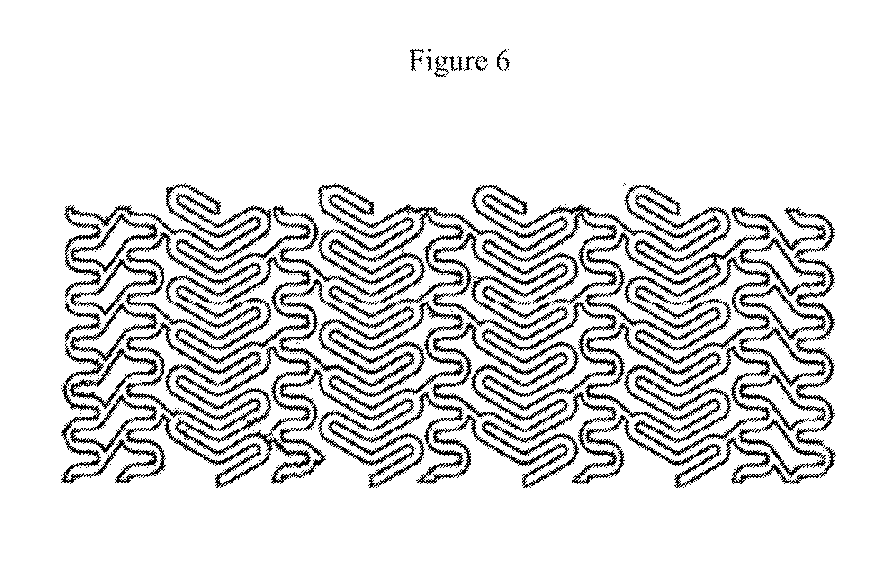
本発明の一実施形態において、前記組成物は、ポリ(L−ラクチド)またはポリ(D−ラクチド)のベースポリマーを有する。有利なベースポリマー組成物としては、ポリ(L−ラクチド)およびポリ(D−ラクチド)のブレンドなどがある。他の有利なベースポリマー組成物としては、D,L−ラクチドコモノマーモル比10〜30%のポリ(L−ラクチド−D,L−ラクチドコポリマー)またはポリ(D−ラクチド−D,L−ラクチドコポリマー)、グリコリドコモノマーモル比10〜20%のポリ(L−ラクチド−グリコリドコポリマー)またはポリ(D−ラクチド−グリコリドコポリマー)などがある。 In one embodiment of the invention, the composition has a base polymer of poly (L-lactide) or poly (D-lactide). Advantageous base polymer compositions include blends of poly (L-lactide) and poly (D-lactide). Other advantageous base polymer compositions include poly (L-lactide-D, L-lactide copolymer) or poly (D-lactide-D, L-lactide copolymer) having a D, L-lactide comonomer molar ratio of 10-30%. ), Glycolide comonomer molar ratio 10-20% poly (L-lactide-glycolide copolymer) or poly (D-lactide-glycolide copolymer).
別の実施形態は、ポリ(L−ラクチド)部分(moiety)および/またはポリ(D−ラクチド)部分を備えたベースポリマーをその修飾コポリマーに結合させたものを具体化し、これには、ポリ(L−ラクチド−トリメチレンカーボネートコポリマー)またはポリ(D−ラクチド−トリメチレンカーボネートコポリマー)および(L−ラクチド−ε−カプロラクトン)、またはポリ(D−ラクチド−ε−カプロラクトンコポリマー)であって、ブロックコポリマーまたはブロック型(blocky)ランダムコポリマーの形態のものが含まれ、その場合、ラクチド鎖長は、部分(moiety)を越えた結晶化をもたらす上で十分である。 Another embodiment embodies a base polymer with a poly (L-lactide) moiety and / or a poly (D-lactide) moiety attached to the modified copolymer, which includes a poly ( L-lactide-trimethylene carbonate copolymer) or poly (D-lactide-trimethylene carbonate copolymer) and (L-lactide-ε-caprolactone) or poly (D-lactide-ε-caprolactone copolymer), a block copolymer Or in the form of a blocky random copolymer, where the lactide chain length is sufficient to provide crystallization beyond the moiety.
別の実施形態において、前記ポリマー組成物は、LおよびD部分(moiety)の前記ラクチドラセミ体(ステレオ複合体)結晶構造の生成を可能にして前記生体吸収性ポリマー医療装置の機械的特性をさらに強化する。前記ラセミ体(ステレオ複合体)結晶構造の形成は、以下の組み合わせなどの配合物から生じさせることができる。 In another embodiment, the polymer composition further enhances the mechanical properties of the bioabsorbable polymer medical device by allowing the formation of the lactidolic (stereocomplex) crystal structure of the L and D moieties. To do. Formation of the racemic (stereocomplex) crystal structure can occur from a formulation such as the following combinations.
ポリ L−ラクチド、ポリ D−ラクチド、およびポリ L−ラクチド−TMCコポリマー
ポリ D−ラクチドおよびポリ L−ラクチド−TMCコポリマー
ポリ L−ラクチドおよびポリ D−ラクチド−TMCコポリマー
ポリ L−ラクチド、ポリ D−ラクチド、およびポリ D−ラクチド−TMCコポリマー
ポリ L−ラクチド−PEGコポリマーおよびポリ D−ラクチド−TMCコポリマー
ポリ D−ラクチド−PEGコポリマーおよびポリ L−ラクチド−TMCコポリマー
本実施形態のポリ−ラクチドラセミ体組成物は、熱を加えることなく「低温で成形可能または曲げ可能である」という特に有利な特徴を有することができる。本発明の、低温で曲げられる骨組みは、キャリア装置にクリンプし、または不規則形状の器官空間に対応する上で十分柔軟になるための外力を必要としない。低温で曲げられる周囲温度は、30℃を超えない室温と定義される。低温で曲げられる骨組みは、例えば、器官空間、例えば脈動する血管の内腔に留置された場合、拡張された骨組み装置に十分な柔軟性をもたらす。例えば、ステントについては、製造後に大部分が非結晶性ポリマー部分(moiety)であり、前記入れ子にされ若しくは端部に配置された二次的な蛇行する支柱が、前記骨組みが、留置のためのバルーン膨張時の伸長によりひずんだとき、特に結晶化可能なポリマー組成物を利用することが望ましい。そのような低温で曲げられるポリマーの骨組み実施形態は、脆性ではなく、曲線的表面を有する体内空間への留置前に柔軟な状態にするための予熱も不要である。低温での可屈曲性により、これらのブレンドはひび割れすることなく室温でクリンプでき、さらに、ひび割れすることなく生理学的条件で拡張可能である。
Poly L-lactide, poly D-lactide, and poly L-lactide-TMC copolymer Poly D-lactide and poly L-lactide-TMC copolymer Poly L-lactide and poly D-lactide-TMC copolymer Poly L-lactide, poly D- Lactide, and poly D-lactide-TMC copolymer Poly L-lactide-PEG copolymer and poly D-lactide-TMC copolymer Poly D-lactide-PEG copolymer and poly L-lactide-TMC copolymer Poly-lactide racemic composition of this embodiment Can have the particularly advantageous feature of being “moldable or bendable at low temperatures” without the application of heat. The low temperature bendable skeleton of the present invention does not require external forces to be crimped to a carrier device or to be sufficiently flexible to accommodate irregularly shaped organ spaces. Ambient temperature bent at low temperature is defined as room temperature not exceeding 30 ° C. Skeletons that are bent at low temperatures, for example, provide sufficient flexibility to an expanded skeleton device when placed in an organ space, such as the lumen of a pulsating blood vessel. For example, for a stent, it is mostly a non-crystalline polymer moiety after manufacture, and the secondary serpentine struts that are nested or placed at the ends are used to place the skeleton for placement. It is desirable to utilize a polymer composition that is particularly crystallizable when distorted by elongation during balloon inflation. Such low temperature bendable polymer framework embodiments are not brittle and do not require preheating to be flexible prior to placement in a body space having a curved surface. Due to the flexibility at low temperatures, these blends can be crimped at room temperature without cracking, and can be expanded under physiological conditions without cracking.
本明細書の実施形態のポリラクチドラセミ体組成物および非ラセミ体組成物は、当該ブレンド組成物に耐衝撃性改良剤を加えた場合でも部分(moiety)を越えた結晶化を可能にするブロック型部分(moiety)を有するよう処理できる。このようなブレンドは、1つまたは2つのTg(ガラス転移点)をもたらすことにより、装置固有のポリマー組成物または混合物を設計できる可能性を生む。 The polylactide racemic and non-racemic compositions of the embodiments herein are block-types that allow crystallization beyond the moiety even when impact modifiers are added to the blend composition. It can be processed to have a moiety. Such blends create the possibility of designing device-specific polymer compositions or mixtures by providing one or two Tg (glass transition points).
ポリラクチドラセミ体組成物は、例えば非ラセミ体PLDL−ラクチドブレンドと比べ、再結晶能力を著しく改善できる。異なるポリラクチド部分(moiety)の有利なラセミ体配列は、例えば、これに限定されるものではないが、必要な留置口径への拡張中の伸長時を含む場合に、異なるポリラクチドステレオ部分(stereomoieties)間でラセミ体結晶を形成できる前記ポリ L−ラクチド−TMCコポリマーと、ポリ−D−ラクチドを混合することにより実現される。このひずみに誘発される結晶化は、有害なひび割れを伴うことなく、結果的に機械的特性を高め、ひいては基材ベースのモジュラスデータに望ましい変化をもたらす。 Polylactide racemic compositions can significantly improve the recrystallization ability compared to, for example, non-racemic PLDL-lactide blends. An advantageous racemic arrangement of different polylactide moieties is, for example, but not limited to, between different polylactide stereo moieties, including when extended during expansion to the required indwelling caliber. The poly L-lactide-TMC copolymer capable of forming a racemic crystal is mixed with poly-D-lactide. This strain-induced crystallization results in enhanced mechanical properties without detrimental cracks, and thus desirable changes in substrate-based modulus data.
組成物のコポリマーとの部分(moiety)を超えた結晶化は、モノマーモル比が約90:10〜50:50範囲のコポリマーに限定されるものと見られる。実際、50:50のモル比ではポリマー部分(moiety)が結晶化に立体障害を及ぼす一方、それを超える比は、部分(moiety)を越えた結晶化に著しく適している。実験的に誘発した結晶化、また各種濃度のラクチドコポリマー、例えばTMCまたはεCLとの種々のブレンドであって、L−ラクチド成分とのラセミ体配列のため過剰なポリ(D−ラクチド)が加えられたものに基づき、ラセミ体組成物における前記コポリマーの効果的濃度は、40%に等しいかそれ未満である。これを受け、部分(moiety)間の結晶化により形成される熱的架橋結合は、伸長またはクリープを軽減するとともに、意図された強化機序を維持する役割を果たす。この有利に強靭なラセミ体組成物は、引張試験でモジュラスデータを向上させ、前記ポリマーブレンドにおける引張強度を軽減する方法を回避する。 Crystallization across the composition with the copolymer appears to be limited to copolymers having a monomer molar ratio in the range of about 90:10 to 50:50. In fact, at a 50:50 molar ratio, the polymer moiety has steric hindrance to crystallization, while ratios above that are remarkably suitable for crystallization beyond the moiety. Experimentally induced crystallization and various blends with various concentrations of lactide copolymers such as TMC or εCL, with excess poly (D-lactide) added due to racemic alignment with the L-lactide component Based on the above, the effective concentration of the copolymer in the racemic composition is less than or equal to 40%. In response, the thermal crosslinks formed by crystallization between the moieties play a role in reducing elongation or creep and maintaining the intended strengthening mechanism. This advantageously tough racemic composition avoids methods of improving modulus data in tensile testing and reducing tensile strength in the polymer blend.
有利なラセミ体組成物の一実施形態は、高残留モノマーレベルの点から劣化を最低限に抑えた生体吸収性ポリマーを提供し、混入モノマーの残留画分が約0.5%を超えないよう、好ましくは約0.3%を超えないようにする。本発明のポリマーの実施形態におけるモノマー混入濃度は、約0.2%まで低減されている。 One embodiment of an advantageous racemic composition provides a bioabsorbable polymer with minimal degradation in terms of high residual monomer levels so that the residual fraction of contaminating monomers does not exceed about 0.5%. Preferably not exceeding about 0.3%. The monomer contamination concentration in the polymer embodiments of the present invention is reduced to about 0.2%.
本明細書で説明する実施形態のポリマー組成物は、当該組成物に対して約70重量%〜約95重量%、または約70重量%〜約80重量%存在するベースポリマーを有することができる。例えば一実施形態において、前記ポリマー配合物は、約70重量%以上のポリ L−ラクチド(約2.5〜3IV)をポリ L−ラクチド−TMCコポリマー(70/30モル比)(1.4〜1.6IV)とともに有することができる。別の実施形態において、前記ポリマー配合物は、70重量%のトリブロックポリ L−ラクチド−PEGコポリマー(99/01モル比)(約2.5〜3IV)をポリ L−ラクチド−TMCコポリマー(70/30モル比)(1.4〜1.6IV)とともに有することができる。さらに、前記ポリマー配合物は、約70重量%のジブロックポリ L−ラクチド−PEG−MMEコポリマー(95/05モル比)(約2.5〜3IV)およびポリ L−ラクチド−TMCコポリマー(70/30モル比)(1.4〜1.6IV)の配合物を有することができる。他の実施形態では、組成物中でε−カプロラクトンが上述のTMCと置き換えられた配合物を提供する。同様に、一実施形態では、PEG−MMEをPEGと置換できる配合物を提供できる。 The polymer composition of the embodiments described herein can have a base polymer present from about 70% to about 95%, or from about 70% to about 80% by weight relative to the composition. For example, in one embodiment, the polymer blend comprises about 70% or more poly L-lactide (about 2.5-3IV) by poly L-lactide-TMC copolymer (70/30 molar ratio) (1.4- 1.6IV). In another embodiment, the polymer blend comprises 70% by weight of triblock poly L-lactide-PEG copolymer (99/01 molar ratio) (about 2.5-3IV) to poly L-lactide-TMC copolymer (70 / 30 molar ratio) (1.4-1.6 IV). Further, the polymer blend comprises about 70% by weight diblock poly L-lactide-PEG-MME copolymer (95/05 molar ratio) (about 2.5-3IV) and poly L-lactide-TMC copolymer (70 / 30 mole ratio) (1.4-1.6 IV). In other embodiments, a formulation is provided in which ε-caprolactone is replaced with the TMC described above in the composition. Similarly, in one embodiment, a formulation that can replace PEG-MME with PEG can be provided.
当該分野で理解されているように、本発明のポリマー組成物は、選ばれた医療装置の種々の要件に対応するようカスタマイズできる。それらの要件としては、生理学的および局所的な解剖学的条件下での機械的強度、弾性、柔軟性、弾力性、および劣化率などがある。具体的な組成物の付加的な効果は、代謝産物の溶解度、親水性および水の取り込み、そして付着するマトリックスまたは封入される医薬品の放出率に関する。 As is understood in the art, the polymer composition of the present invention can be customized to meet the various requirements of a selected medical device. These requirements include mechanical strength, elasticity, flexibility, elasticity, and rate of degradation under physiological and local anatomical conditions. Additional effects of specific compositions relate to metabolite solubility, hydrophilicity and water uptake, and the rate of release of the adhering matrix or encapsulated pharmaceutical.
前記ポリマーインプラントの実用性は、質量損失、分子量の減少、機械的特性の保持、および/または組織反応を測定することにより評価できる。骨組みとしてより重要な性能は、加水分解安定性、熱転移、結晶化度、および配向である。骨組み性能に悪影響を及ぼす他の決定要因としては、モノマー不純物、環式および非環式オリゴマー、構造的欠陥、および老朽化などがあるが、これに限定されるものではない。 The utility of the polymer implant can be evaluated by measuring mass loss, molecular weight reduction, retention of mechanical properties, and / or tissue response. More important performance as a framework is hydrolytic stability, thermal transition, crystallinity, and orientation. Other determinants that adversely affect skeletal performance include, but are not limited to, monomer impurities, cyclic and acyclic oligomers, structural defects, and aging.
上記のポリマー組成物から作製された医療装置は、押出成形または金型成形の後、有意に非結晶性の可能性がある。そのような装置は、制御下で再結晶化を行うことにより、結晶化度を漸進的に進め、機械的強度を高めることができる。装置配備時にひずみが導入されると、結晶化をさらに誘発することができる。そのような漸進的再結晶化は、二次的または最終的な製造(例えば、レーザー切断による)前の「ブランク」装置上、またはそのような二次的製造後のどちらかで行える。また、結晶化(したがって機械的特性)は、付加的な製造加工前に、ポリマーチューブ、中空繊維、シートまたは膜、あるいはモノフィラメントの「冷間」引き抜きなどでひずみを導入することにより、最大限に伸ばすことができる。結晶化度は、前記医療装置の剛性強化に寄与することが認められている。そのため、前記骨組みのポリマー組成物および立体複合体は、非結晶性およびパラ結晶性双方の部分(moiety)を有する。初期に半結晶性であったポリマー部分は、所与の装置を伸長または拡張して操作できる。しかし、前記ポリマー装置の柔軟性および弾性を達成するには、十分な量の非結晶性ポリマー特性が望まれる。通常のモノマー成分としては、ラクチド、グリコリド、カプロラクトン、ジオキサノン、およびトリメチレンカーボネートなどがある。また、前記ステントは、生体吸収中に前記ポリマー構造上で灌流し、これに作用する局所組織または循環器の生物活性因子および酵素に対し、比較的均一な露出を実現するよう構成されている。 Medical devices made from the above polymer compositions can be significantly non-crystalline after extrusion or molding. Such an apparatus can progressively increase the crystallinity and increase the mechanical strength by performing recrystallization under control. If strain is introduced during device deployment, crystallization can be further induced. Such gradual recrystallization can be performed either on a “blank” device before secondary or final manufacturing (eg, by laser cutting) or after such secondary manufacturing. Crystallization (and therefore mechanical properties) can be maximized by introducing strain, such as “cold” drawing of polymer tubes, hollow fibers, sheets or membranes, or monofilaments, before additional manufacturing processing. Can be stretched. It has been observed that crystallinity contributes to the rigidity enhancement of the medical device. As such, the framework polymer composition and steric complex have both amorphous and paracrystalline moieties. The polymer portion that was initially semi-crystalline can be manipulated by stretching or expanding a given device. However, a sufficient amount of amorphous polymer properties is desired to achieve the flexibility and elasticity of the polymer device. Common monomer components include lactide, glycolide, caprolactone, dioxanone, and trimethylene carbonate. The stent is also configured to achieve relatively uniform exposure to local tissue or cardiovascular bioactive factors and enzymes that perfuse over and act on the polymer structure during bioabsorption.
有利なことに、器官空間インプラント、例えば心臓血管ステントの前記ポリマーマトリックスのin situ分解反応速度は、組織の過負荷、炎症反応、または他の比較的有害な影響を回避する上で十分緩やかである。一実施形態において、前記骨組みは、少なくとも1か月存続するよう製造される。 Advantageously, the in situ degradation kinetics of the polymer matrix of organ space implants, such as cardiovascular stents, are slow enough to avoid tissue overload, inflammatory reactions, or other relatively harmful effects . In one embodiment, the skeleton is manufactured to last at least one month.
前記ポリマーには、例えば当該ポリマーの活性部位にグラフト重合またはコーティングを行うことにより、医薬組成物を導入できる。本発明に係るポリマーの一実施形態では、前記ポリマーマトリックスまたはポリマーコーティングに生体治癒因子または他の薬剤を付着させ、または導入することが可能である。 A pharmaceutical composition can be introduced into the polymer, for example, by performing graft polymerization or coating on the active site of the polymer. In one embodiment of the polymer according to the present invention, a biohealing factor or other drug can be attached to or introduced into the polymer matrix or polymer coating.
別の実施形態では、前記ポリマーマトリックスに薬剤を構造的に封入し、または付着させるよう前記組成物を構成できる。そのような添加剤の目的は、例えばステントについては、前記医療装置ポリマーが接触する心臓血管系または血管部位の治療を提供することである。前記ポリマーにおける薬剤の封入または付着の種類は、前記装置からの放出率を左右する。例えば、前記ポリマーマトリックスには、これに限定されるものではないが、共有結合、非極性結合のほか、エステルまたは同様な生体可逆性結合手段を含む種々の既知の方法で、前記薬剤または他の添加剤を結合させることができる。 In another embodiment, the composition can be configured to structurally encapsulate or attach a drug to the polymer matrix. The purpose of such additives is, for example, for stents, to provide treatment of the cardiovascular system or site where the medical device polymer contacts. The type of drug encapsulation or attachment in the polymer will determine the rate of release from the device. For example, the polymer matrix may be a variety of known methods including, but not limited to, covalent bonds, non-polar bonds, as well as esters or similar bioreversible binding means, such as, but not limited to, Additives can be combined.
一実施形態において、生体吸収性の体内留置可能な医療装置は、1若しくはそれ以上の障壁層を含む生物分解性および生体吸収性のコーティングで覆うことができ、前記ポリマーマトリックスは、以上に述べた医薬物質のうち1若しくはそれ以上を含む。この実施形態において、前記障壁層は、以下を含む適切な生物分解性ポリマーを含む適切な生物分解性材料を有することができるが、これに限定されるものではない。ポリエステル、例えばPLA、PGA、PLGA、PPF、PCL、PCC、TMC、およびこれらの任意のコポリマー;ポリカルボン酸、無水マレイン酸ポリマーを含むポリ無水物;ポリオルトエステル;ポリアミノ酸;ポリエチレンオキシド;polyphosphacenes;ポリ乳酸、ポリグリコール酸とそのコポリマーおよび混合物、例えばポリ(L−乳酸)(PLLA)、ポリ(D,L−ラクチド)、ポリ(乳酸−グリコール酸コポリマー)、50/50(DL−ラクチド−グリコリドコポリマー);polydixanone;ポリプロピレンフマラート;ポリデプシペプチド;ポリカプロラクトンとそのコポリマーおよび混合物、例えばポリ(D,L−ラクチド−カプロラクトンコポリマー)およびポリカプロラクトン−アクリル酸ブチルコポリマー;吉草酸ポリヒドロキシブチラートとそのブレンド;ポリカーボネート、例えばチロシン由来のポリカーボネートおよびアリール化物(arylates)、ポリイミノカーボネート、およびポリジメチルトリメチルカーボネート;シアノアクリレート;リン化カルシウム;ポリグリコサミノグリカン;巨大分子、例えば多糖類(ヒアルロン酸;セルロース、およびヒドロキシプロピルメチルセルロース;ゼラチン;デンプン;デキストラン;アルギン酸塩とその誘導体を含む)、タンパク質、およびポリペプチド;ならびに以上のいずれかの混合物およびコポリマー。また、前記生物分解性ポリマーは、表面侵食可能なポリマー、例えばポリヒドロキシブチラートとそのコポリマー、ポリカプロラクトン、ポリ無水物(結晶性および非結晶性の双方)、無水マレイン酸コポリマー、およびリン酸亜鉛カルシウムとすることもできる。装置上のポリマーの骨組みが有することのできる障壁層の数は、患者の治療に必要とされる量に応じて異なる。例えば、治療が長期的になるほど、その期間中に必要とされる治療用の物質、医薬物質を適切なタイミングで提供するための障壁層の数も増える。 In one embodiment, a bioabsorbable indwellable medical device can be covered with a biodegradable and bioabsorbable coating that includes one or more barrier layers, the polymer matrix described above. Contains one or more of the medicinal substances. In this embodiment, the barrier layer can have a suitable biodegradable material including, but not limited to, a suitable biodegradable polymer including: Polyesters such as PLA, PGA, PLGA, PPF, PCL, PCC, TMC, and any copolymers thereof; polycarboxylic anhydrides, polyanhydrides including maleic anhydride polymers; polyorthoesters; polyamino acids; polyethylene oxides; Polylactic acid, polyglycolic acid and copolymers and mixtures thereof, such as poly (L-lactic acid) (PLLA), poly (D, L-lactide), poly (lactic acid-glycolic acid copolymer), 50/50 (DL-lactide-glycolide) Copolymer); polydixone; polypropylene fumarate; polydepsipeptide; polycaprolactone and copolymers and mixtures thereof, such as poly (D, L-lactide-caprolactone copolymer) and polycaprolactone- Polybutylbutyrate copolymer; valeric acid polyhydroxybutyrate and blends thereof; polycarbonates such as tyrosine-derived polycarbonates and arylates, polyiminocarbonates, and polydimethyltrimethyl carbonates; cyanoacrylates; calcium phosphide; polyglycosamino Glycans; macromolecules such as polysaccharides (hyaluronic acid; cellulose and hydroxypropylmethylcellulose; gelatin; starch; dextran; including alginate and its derivatives), proteins, and polypeptides; and mixtures and copolymers of any of the foregoing. The biodegradable polymer may also be a surface erodible polymer such as polyhydroxybutyrate and copolymers thereof, polycaprolactone, polyanhydrides (both crystalline and non-crystalline), maleic anhydride copolymers, and zinc phosphate It can also be calcium. The number of barrier layers that the polymer framework on the device can have depends on the amount required to treat the patient. For example, the longer the treatment, the greater the number of barrier layers required to provide the therapeutic and pharmaceutical substances needed at that time.
別の実施形態において、前記ポリマー組成物中の前記添加剤は、前記マトリックス内の複数成分の医薬組成物の形態にでき、例えば早期の新生内膜過形成または平滑筋細胞の遊走および増殖を遅延させる持続放出医薬製剤および管の開存性を保つ長時間作用型の薬剤または血管径を拡大させる薬剤を放出する二次的な生体内安定性のマトリックス、例えば血管内皮型一酸化窒素合成酵素(endothelial nitric oxide synthase:eNOS)、一酸化窒素供与体とその誘導体、例えばアスピリンまたはその誘導体、一酸化窒素生成ヒドロゲル、PPAR作動薬、例えばPPAR−α gands、組織プラスミノーゲン活性化因子、スタチン、例えばアトルバスタチン、エリスロポエチン、darbepotin、セリンプロテイナーゼ−1(serine proteinase−1:SERP−1)およびプラバスタチン、ステロイド、および/または抗生物質を含む。 In another embodiment, the additive in the polymer composition can be in the form of a multi-component pharmaceutical composition within the matrix, for example, to delay early neointimal hyperplasia or smooth muscle cell migration and proliferation. Sustained-release pharmaceutical formulations and long-acting drugs that preserve the patency of the tube or secondary biostable matrices that release drugs that enlarge the vessel diameter, such as vascular endothelial nitric oxide synthase ( endothelial toxic oxide synthase (eNOS), nitric oxide donors and derivatives thereof, such as aspirin or derivatives thereof, nitric oxide producing hydrogels, PPAR agonists such as PPAR-α gands, tissue plasminogen activators, statins such as Atorvastatin, erythropoietin, darbepotin , Serine proteinase-1 (SERP-1) and pravastatin, steroids and / or antibiotics.
医薬組成物は、前記ポリマーに導入でき、または前記ポリマーの混合および押出成形後、スプレー、ディッピング、または塗布により、あるいはマイクロカプセル化したのち当該ポリマー混合物に混合して、当該ポリマーの表面にコーティングできる。米国特許第6,020,385号。前記医薬組成物は、共有結合により前記ポリマーブレンドに結合されるとき、ヘテロまたはホモ二官能性架橋剤により結合される(http://www.piercenet.com/products/browse.cfm?fldID=020306を参照)。 The pharmaceutical composition can be introduced into the polymer or coated on the surface of the polymer after mixing and extruding the polymer, by spraying, dipping or coating, or microencapsulated and then mixed with the polymer mixture. . US Patent No. 6,020,385. When the pharmaceutical composition is covalently attached to the polymer blend, it is bound by a hetero- or homobifunctional cross-linker (http://www.piercenet.com/products/browse.cfm?fldID=020306 See).
前記ステントに導入でき、または前記ステントにコーティングできる薬剤としては、以下が含まれるが、これに限定されるものではない。(i)薬剤、例えば(a)抗血栓剤、例えばヘパリン、ヘパリン誘導体、ウロキナーゼ、およびPPack(デキストロフェニルアラニン・プロリン・アルギニン・クロロメチルケトン);(b)抗炎症剤、例えばデキサメタゾン、プレドニゾロン、コルチコステロン、ブデソニド、エストロゲン、スルファサラジン、およびメサラミン;(c)抗腫瘍性剤、抗増殖性剤、または抗有糸分裂性剤、例えばパクリタキセル、5−フルオロウラシル、シスプラチン、ビンブラスチン、ビンクリスチン、エポチロン、エンドスタチン、アンギオスタチン、アンギオペプチン、平滑筋細胞の増殖を阻害できるモノクローナル抗体、チミジンキナーゼ阻害剤、ラパマイシン、40−0−(2−ヒドロキシエチル)ラパマイシン(エベロリムス)、40−0−ベンジル−ラパマイシン、40−0(4'−ヒドロキシメチル)ベンジル−ラパマイシン、40−0−[4'−(1,2−ジヒドロキシエチル)]ベンジル−ラパマイシン、40−アリル−ラパマイシン、40−0−[3'−(2,2−ジメチル−1,3−ジオキソラン−4(S)−yl−prop−2'−en−l'−yl]−20 ラパマイシン、(2':E,4'S)−40−0−(4',5'.:ジヒドロキシペント−2'−en−l'−yl)、ラパマイシン 40−0(2 ヒドロキシ) エトキシカルボニルメチル−ラパマイシン、40−0−(3−ヒドロキシプロピル−ラパマイシン 40−0−((ヒドロキシ)へキシル−ラパマイシン 40−0−[2−(2−ヒドロキシ)エトキシ]エチル−ラパマイシン、40−0−[(3S)−2,2ジメチルジオキソラン−3−yl]メチル−ラパマイシン、40−0−[(2S)−2,3−ジヒドロキシプロプ−l−yl]−ラパマイシン、40−0−(2−アセトキシ)ethyl−ラパマイシン、40−0−(2−ニコチノイルオキシ)エチル−ラパマイシン、40−0−[2−(N−25 モルホリノ)アセトキシエチル−ラパマイシン、40−0−(2−N−イミダゾリルアセトキシ)エチル−ラパマイシン、40−0[2−(N−メチル−N'−ピペラジニル)アセトキシ]エチル−ラパマイシン、39−0−デスメチル−3.9,40−0,0 エチレン−ラパマイシン、(26R)−26−ジヒドロ−40−0−(2−ヒドロキシ)エチル−ラパマイシン、28−0 Methyrapamycin、40−0−(2−アミノエチル)−ラパマイシン、40−0−(2−アセトアミノエチル)−ラパマイシン、40−0(2−ニコチンアミドエチル)−ラパマイシン、40−0−(2−(N−メチル−イミダゾ−2' ylcarbcthoxamido)エチル)−30 ラパマイシン、40−0−(2−エトキシカルボニルアミノエチル)−ラパマイシン、40−0−(2−トリルスルホンアミドエチル)−ラパマイシン、40−0−[2−(4',5'−ジカルボエトキシ−1',2';3'−triazol−l'−yl)−エチル]ラパマイシン、42−Epi−(telrazolyl)ラパマイシン(タクロリムス)、および42−[3−ヒドロキシ−2−(ヒドロキシメチル)−2−メチルプロパノアート]ラパマイシン(テムシロリムス)(WO2008/086369);(d)麻酔薬、例えばリドカイン、ブピバカイン、およびロピバカイン;(e)抗凝固薬、例えばD−Phe−Pro−Argクロロメチルケトン、RGDペプチド含有化合物、ヘパリン、ヒルジン、抗トロンビン化合物、血小板受容体拮抗薬、抗トロンビン抗体、抗血小板受容体抗体、アスピリン、プロスタグランジン阻害剤、血小板阻害剤、およびダニ抗血小板ペプチド;(f)血管細胞成長促進剤、例えば成長因子、転写活性化因子、および翻訳促進剤;(g)血管細胞成長阻害剤、例えば成長因子阻害剤、成長因子受容体拮抗薬、転写抑制剤、翻訳抑制剤、複製阻害剤、阻害抗体、成長因子に対する抗体、成長因子および細胞毒素から成る二官能性分子、抗体および細胞毒素から成る二官能性分子;(h)タンパク質キナーゼおよびチロシンキナーゼ阻害剤(例えば、チルホスチン、ゲニステイン、キノキサリン);(i)プロスタサイクリン類似体;(j)コレステロール低下剤;(k)アンジオポイエチン;(l)抗菌剤、例えばトリクロサン、セファロスポリン、アミノグリコシド、およびニトロフラントイン;(m)細胞毒性剤、細胞増殖抑制剤、および細胞増殖影響因子;(n)血管拡張剤;および(o)内因性血管作用機構を妨げる薬剤、(ii)アンチセンスDNAおよびRNAのほか、以下のためのDNAコーディングを含む遺伝子治療剤(a)アンチセンスRNA、(b)欠陥または欠損した内因性分子に置き換わるtRNAまたはrRNA、(c)成長因子、例えば酸性およびアルカリ性線維芽細胞成長因子、血管内皮成長因子、上皮成長因子、形質転換成長因子aおよびP、血小板由来の内皮成長因子、血小板由来の成長因子、腫瘍壊死因子、肝細胞成長因子、およびインスリン様成長因子を含む血管新生因子、(d)CD阻害剤を含む細胞周期阻害剤、および(e)チミジンキナーゼ(「T」)および細胞増殖を妨げる上で有用な他の薬剤。 Agents that can be introduced into or coated on the stent include, but are not limited to: (I) drugs, such as (a) antithrombotic agents such as heparin, heparin derivatives, urokinase, and PPack (dextrophenylalanine, proline, arginine, chloromethyl ketone); (b) anti-inflammatory agents such as dexamethasone, prednisolone, corti Costerone, budesonide, estrogens, sulfasalazine, and mesalamine; (c) antitumor agents, antiproliferative agents, or antimitotic agents such as paclitaxel, 5-fluorouracil, cisplatin, vinblastine, vincristine, epothilone, endostatin , Angiostatin, angiopeptin, monoclonal antibody capable of inhibiting smooth muscle cell proliferation, thymidine kinase inhibitor, rapamycin, 40-0- (2-hydroxyethyl) rapamycin (everolimus), 40- Benzyl-rapamycin, 40-0 (4′-hydroxymethyl) benzyl-rapamycin, 40-0- [4 ′-(1,2-dihydroxyethyl)] benzyl-rapamycin, 40-allyl-rapamycin, 40-0- [3 ′-(2,2-dimethyl-1,3-dioxolane-4 (S) -yl-prop-2′-en-l′-yl] -20 rapamycin, (2 ′: E, 4 ′S) -40-0- (4 ', 5' .: dihydroxypent-2'-en-1'-yl), rapamycin 40-0 (2 hydroxy) ethoxycarbonylmethyl-rapamycin, 40-0- (3-hydroxypropyl -Rapamycin 40-0-((hydroxy) hexyl-Rapamycin 40-0- [2- (2-hydroxy) ethoxy] ethyl-rapamycin, 40-0-[(3S) -2 , 2 dimethyldioxolane-3-yl] methyl-rapamycin, 40-0-[(2S) -2,3-dihydroxyprop-1-yl] -rapamycin, 40-0- (2-acetoxy) ethyl-rapamycin, 40 -0- (2-nicotinoyloxy) ethyl-rapamycin, 40-0- [2- (N-25 morpholino) acetoxyethyl-rapamycin, 40-0- (2-N-imidazolylacetoxy) ethyl-rapamycin, 40- 0 [2- (N-methyl-N′-piperazinyl) acetoxy] ethyl-rapamycin, 39-0-desmethyl-3.9,40-0,0 ethylene-rapamycin, (26R) -26-dihydro-40-0 -(2-Hydroxy) ethyl-rapamycin, 28-0 Methyrapamycin, 40-0- (2-A Minoethyl) -rapamycin, 40-0- (2-acetaminoethyl) -rapamycin, 40-0 (2-nicotinamidoethyl) -rapamycin, 40-0- (2- (N-methyl-imidazo-2 'ylcarbbcoxamido) Ethyl) -30 rapamycin, 40-0- (2-ethoxycarbonylaminoethyl) -rapamycin, 40-0- (2-tolylsulfonamidoethyl) -rapamycin, 40-0- [2- (4 ′, 5′- Dicarboethoxy-1 ′, 2 ′; 3′-triazol-l′-yl) -ethyl] rapamycin, 42-Epi- (telrazolyl) rapamycin (tacrolimus), and 42- [3-hydroxy-2- (hydroxymethyl) ) -2-Methylpropanoate] rapamycin (temsirolimus) (WO200 (086369); (d) anesthetics such as lidocaine, bupivacaine and ropivacaine; (e) anticoagulants such as D-Phe-Pro-Arg chloromethyl ketone, RGD peptide-containing compounds, heparin, hirudin, antithrombin compounds, Platelet receptor antagonists, antithrombin antibodies, antiplatelet receptor antibodies, aspirin, prostaglandin inhibitors, platelet inhibitors, and tick antiplatelet peptides; (f) vascular cell growth promoters such as growth factors, transcriptional activation (G) vascular cell growth inhibitors such as growth factor inhibitors, growth factor receptor antagonists, transcription inhibitors, translation inhibitors, replication inhibitors, inhibitory antibodies, antibodies to growth factors, growth A bifunctional molecule comprising a factor and a cytotoxin, a bifunctional molecule comprising an antibody and a cytotoxin; (h) a tamper Protein kinases and tyrosine kinase inhibitors (eg, tyrphostin, genistein, quinoxaline); (i) prostacyclin analogs; (j) cholesterol-lowering agents; (k) angiopoietin; (l) antibacterial agents such as triclosan, cephalo Sporins, aminoglycosides, and nitrofurantoins; (m) cytotoxic agents, cytostatics, and cell growth influencing factors; (n) vasodilators; and (o) agents that interfere with the mechanism of endogenous vasoactivity, (ii) ) In addition to antisense DNA and RNA, gene therapy agents comprising DNA coding for: (a) antisense RNA, (b) tRNA or rRNA that replaces defective or defective endogenous molecules, (c) growth factors such as Acidic and alkaline fibroblast growth factor, vascular endothelial growth factor, (D) CD inhibition, including skin growth factor, transforming growth factors a and P, platelet-derived endothelial growth factor, platelet-derived growth factor, tumor necrosis factor, hepatocyte growth factor, and insulin-like growth factor Cell cycle inhibitors, including agents, and (e) thymidine kinase ("T") and other agents useful in preventing cell proliferation.
前記ステントに導入できる他の薬剤としては、以下が含まれるが、これに限定されるものではない。アカルボース、抗原、β受容体遮断薬、非ステロイド性抗炎症薬(non−steroidal antiinflammatory drugs:NSAID、強心配糖体、アセチルサリチル酸、ウイルス抑制薬、アクラルビシン、アシクロビル、シスプラチン、アクチノマイシン、αおよびβ交感神経興奮剤(dmeprazole、アロプリノール、アルプロスタジル、プロスタグランジン、アマンタジン、アンブロキソール、アムロジピン、メトトレキサート、S−アミノサリチル酸、アミトリプチリン、アモキシシリン、アナストロゾール、アテノロール、アザチオプリン、バルサラジド、ベクロメタゾン、ベタヒスチン、ベザフィブラート、ビカルタミド、ジアゼパムおよびジアゼパム誘導体、ブデソニド、ブフェキサマク、ブプレノルフィン、メタドン、カルシウム塩、カリウム塩、マグネシウム塩、カンデサルタン、カルバマゼピン、カプトプリル、セファロスポリン、セチリジン、ケノデオキシコール酸、ウルソデオキシコール酸、テオフィリンおよびテオフィリン誘導体、トリプシン、シメチジン、クラリスロマイシン、クラブラン酸、クリンダマイシン、クロブチノール、クロニジン、コトリモキサゾール、コデイン、カフェイン、ビタミンDおよびビタミンD誘導体、コレスチラミン、クロモグリク酸、クマリンおよびクマリン誘導体、システイン、シタラビン、シクロホスファミド、シクロスポリン、シプロテロン、シタバリン(cytabarine)、ダピプラゾール、デソゲストレル、デソニド、ジヒドララジン、ジルチアゼム、麦角アルカロイド、ジメンヒドリナート、ジメチルスルホキシド、ジメチコン、ドンペリドンおよびドンペリドン誘導体(domperidone and domperidan derivatives)、誘導体、ドーパミン、ドキサゾシン、ドキソルビジン(doxorubizin)、ドキシラミン、ダピプラゾール、ベンゾジアゼピン、ジクロフェナク、グリコシド抗生物質、デシプラミン、エコナゾール、ACE阻害剤、エナラプリル、エフェドリン、エピネフリン、エリスロポエチンおよびエリスロポエチン誘導体、モルフィナン、カルシウム拮抗薬、イリノテカン、モダフミル(modafmil)、オルリスタット、ペプチド抗生物質、フェニトイン、リルゾール、リセドロネート、シルデナフィル、トピラマート、マクロライド抗生物質、エストロゲンおよびエストロゲン誘導体、プロゲストゲンおよびプロゲストゲン誘導体、テストステロンおよびテストステロン誘導体、アンドロゲンアンドロゲン誘導体、エテンザミド、エトフェナメート、エトフィブラート、フェノフィブラート、etofylHne、エトポシド、ファムシクロビル、ファモチジン、フェロジピン、フェノフィブラート、フェンタニル、フェンチコナゾール、ジャイレース阻害剤、フルコナゾール、フルダラビン、フルアリジン(fluarizine)、フルオロウラシル、フルオキセチン、フルルビプロフェン、イブプロフェン、フルタミド、フルバスタチン、ホリトロピン、フォルモテロール、ホスホマイシン(fosfomicin)、フロセミド、フシジン酸、ガロパミル、ガンシクロビル(ganciclovir)、ゲムフィブロジル、ゲンタマイシン(gentamicin)、イチョウ、セイヨウオトギリソウ、グリベンクラミド、経口抗糖尿病剤としての尿素誘導体、グルカゴン、グルコサミンおよびグルコサミン誘導体、グルタチオン、グリセロールおよびグリセロール誘導体、視床下部ホルモン、ゴセレリン、ジャイレース阻害剤、グアネチジン、ハロファントリン、ハロペリドール、ヘパリンおよびヘパリン誘導体、ヒアルロン酸、ヒドララジン、ヒドロクロロチアジドおよびヒドロクロロチアジド誘導体、サリチレート、ヒドロキシジン、イダルビシン、イホスファミド、イミプラミン、インドメタシン、インドラミン(indoramine)、インスリン、インターフェロン、ヨウ素およびヨウ素誘導体、イソコナゾール、イソプレナリン、グルシトールおよびグルシトール誘導体、イトラコナゾール、ケトコナゾール、ケトプロフェン、ケトチフェン、ラシジピン、ランソプラゾール、レボドパ、レボメタドン、甲状腺ホルモン、リポ酸およびリポ酸誘導体、リシノプリル、リスリド、ロフェプラミン、ロムスチン、ロペラミド、ロラタジン、マプロチリン、メベンダゾル、メベベリン、メクロジン、メフェナム酸、メフロキン、メロキシカム、メピンドロール、メプロバメート、メロペネム、メサラジン、メスクシミド、メタミゾール、メトホルミン、メトトレキサート、メチルフェニデート、メチルプレドニゾロン、メチキセン、メトクロプラミド、メトプロロール、メトロニダゾール、ミアンセリン、ミコナゾール、ミノサイクリン、ミノキシジル、ミソプロストール、マイトマイシン、ミゾラスチン、モエキシプリル、モルヒネおよびモルヒネ誘導体、オオマツヨイグサ、ナルブフィン、ナロキソン、チリジン、ナプロキセン、ナルコチン、ナタマイシン、ネオスチグミン、ニセルゴリン、ニケタミド、ニフェジピン、ニフルム酸、ニモジピン、ニモラゾール、ニムスチン、ニソルジピン、アドレナリンおよびアドレナリン誘導体、ノルフロキサシン、ノバミンスルホン(novamine sulfone)、ノスカピン、ナイスタチン、オフロキサシン、オランザピン、オルサラジン、オメプラゾール、オモコナゾール、オンダンセトロン、オキサセプロール、オキサシリン、オキシコナゾール、オキシメタゾリン、パントプラゾール、パラセタモール、パロキセチン、ペンシクロビル、経口ペニシリン、ペンタゾシン、ペンチフィリン、ペントキシフィリン、パーフェナジン、ペチジン、植物抽出物、フェナゾン、フェニラミン、バルビツール酸誘導体、フェニルブタゾン、フェニトイン、ピモジド、ピンドロール、ピペラジン、ピラセタム、ピレンゼピン、ピリベジル、ピロキシカム、プラミペキソール、プラバスタチン、プラゾシン、プロカイン、プロマジン、プロピベリン、プロプラノロール、プロピフェナゾン、プロスタグランジン、プロチオナミド、プロキシフィリン、クエチアピン、キナプリル、キナプリラト(quinaprilat)、ラミプリル、ラニチジン、レプロテロール、レセルピン、リバビリン、リファンピシン、リスペリドン、リトナビル、ロピニロール、ロキサチジン、ロキシスロマイシン、ルスコゲニン、ルトシドおよびルトシド誘導体、サバジラ、サルブタモール、サルメテロール、スコポラミン、セレギリン、セルタコナゾール、セルチンドール、セルトラリオン(sertralion)、ケイ酸塩、シルデナフィル、シンバスタチン、シトステロール、ソタロール、スパグルム酸、スパルフロキサシン、スペクチノマイシン、スピラマイシン、スピラプリル、スピロノラクトン、スタブジン、ストレプトマイシン、スクラルファート、スフェンタニル、スルバクタム、スルホンアミド、スルファサラジン、スルピリド、スルタミシリン、スルチアム、スマトリプタン、塩化スキサメトニウム、タクリン、タクロリムス、タリオロール(taliolol)、タモキシフェン、タウロリジン、タザロテン、テマゼパム、テニポシド、テノキシカム、テラゾシン、テルビナフィン、テルブタリン、テルフェナジン、テルリプレシン、テルタトロール、テトラサイクリン、テリゾリン(teryzoline)、テオブロミン、テオフィリン、ブチジン(butizine)、チアマゾール、フェノチアジン、チオテパ、チアガビン、チアプリド、プロピオン酸誘導体、チクロピジン、チモロール、チニダゾール、チオコナゾール、チオグアニン、チオキソロン、チロプラミド、チザニジン、トラゾリン、トルブタミド、トルカポン、トルナフテート、トルペリゾン、トポテカン、トラセミド、抗エストロゲン、トラマドール、トラマゾリン、トランドラプリル、トラニルシプロミン、トラピジル、トラゾドン、トリアムシノロンおよびトリアムシノロン誘導体、トリアムテレン、トリフルペリドール、トリフルリジン、トリメトプリム、トリミプラミン、トリペレナミン、トリプロリジン、トリフォスファミド(trifosfamide)、トロマンタジン、トロメタモール、トロパルピン(tropalpin)、トロキセルチン(troxerutine)、ツロブテロール、チラミン、チロトリシン、ウラピジル、ウルソデオキシコール酸、ケノデオキシコール酸、バラシクロビル、バルプロ酸、バンコマイシン、塩化ベクロニウム、バイアグラ、ベンラファクシン、ベラパミル、ビダラビン、ビガバトリン、ビロアジン(viloazine)、ビンブラスチン、ビンカミン、ビンクリスチン、ビンデシン、ビノレルビン、ビンポセチン、ビクイジル(viquidil)、ワルファリン、ニコチン酸キサンチノール、キシパミド、ザフィルルカスト、ザルシタビン、ジドブジン、ゾルミトリプタン、ゾルピデム、ゾプリコン(zoplicone)、ゾチピン(zotipine)など。例えば、米国特許第6,897,205号、第6,838,528号、および第6,497,729号を参照。 Other drugs that can be introduced into the stent include, but are not limited to: Acarbose, antigen, beta-receptor blocker, non-stereoidal anti-inflammatory drugs (NSAID), cardiac glycoside, acetylsalicylic acid, virus inhibitor, aclarubicin, acyclovir, cisplatin, actinomycin, alpha and beta sympathy Neurostimulants (dmeprazole, allopurinol, alprostadil, prostaglandin, amantadine, ambroxol, amlodipine, methotrexate, S-aminosalicylic acid, amitriptyline, amoxicillin, anastrozole, atenolol, azathioprine, balsalazide, beclomethasone, betahistol , Bicalutamide, diazepam and diazepam derivatives, budesonide, bufexamac, bupre Norphine, methadone, calcium salt, potassium salt, magnesium salt, candesartan, carbamazepine, captopril, cephalosporin, cetirizine, chenodeoxycholic acid, ursodeoxycholic acid, theophylline and theophylline derivatives, trypsin, cimetidine, clarithromycin, clavulanic acid, Clindamycin, clobutinol, clonidine, cotrimoxazole, codeine, caffeine, vitamin D and vitamin D derivatives, cholestyramine, cromoglycic acid, coumarin and coumarin derivatives, cysteine, cytarabine, cyclophosphamide, cyclosporine, cyproterone, Cytabaline, dapiprazole, desogestrel, desonide, dihydralazine, diltiazem, ergot alkaloids, Menhydrinate, Dimethylsulfoxide, Dimethicone, Domperidone and Domperidone derivatives Inhibitors, enalapril, ephedrine, epinephrine, erythropoietin and erythropoietin derivatives, morphinan, calcium antagonists, irinotecan, modafmil, orlistat, peptide antibiotics, phenytoin, riluzole, risedronate, sildenafil, topiramate, macrolide Strogen and estrogen derivatives, progestogen and progestogen derivatives, testosterone and testosterone derivatives, androgen androgen derivatives, etenzamide, etofenamate, etofibrate, fenofibrate, etofylHne, etoposide, famciclovir, famotidine, felodipine, fenofibrate, Fentanyl, fenticonazole, gyrase inhibitor, fluconazole, fludarabine, fluarizine, fluorouracil, fluoxetine, flurbiprofen, ibuprofen, flutamide, fluvastatin, follitropin, formoterol, fosfomycin, fosemidin , Galopamil, ganciclovir (g anciclovir), gemfibrozil, gentamicin, ginkgo biloba, hypericum perforatum, glibenclamide, urea derivatives as oral antidiabetic agents, glucagon, glucosamine and glucosamine derivatives, glutathione, glycerol and glycerol derivatives, hypothalamic hormone, goserelin, gyrase inhibitor , Guanethidine, halophanthrin, haloperidol, heparin and heparin derivatives, hyaluronic acid, hydralazine, hydrochlorothiazide and hydrochlorothiazide derivatives, salicylate, hydroxyzine, idarubicin, ifosfamide, imipramine, indomethacin, indolamine, insulin, interferon and iodine Derivatives, iso Nazole, isoprenaline, glucitol and glucitol derivatives, itraconazole, ketoconazole, ketoprofen, ketotifen, rasidipine, lansoprazole, levodopa, levmethadone, thyroid hormone, lipoic acid and lipoic acid derivatives, lisinopril, lisuride, lofepramine, lomusadroline, lopermendrazol , Mebevelin, Meclozine, Mefenamic acid, Mefloquine, Meloxicam, Mepindolol, Meprobamate, Meropenem, Mesalazine, Mesuximide, Metamizole, Metformin, Methotrexate, Methylphenidate, Methylprednisolone, Methixene, Metoclopramide, Metopromizomidoricoline, Metronidazole Jill, misoprostol, mitomycin, mizolastine, moexipril, morphine and morphine derivatives, evening primrose, nalbuphine, naloxone, thyridine, naproxen, narcotine, natamycin, neostigmine, nicergoline, niketamide, nifedipine, niflumizine, nifluzolpine, nifluzolpine Adrenaline and adrenaline derivatives, norfloxacin, novamin sulfone, noscapine, nystatin, ofloxacin, olanzapine, olsalazine, omeprazole, omoconazole, ondansetron, oxaceptol, oxacillin, oxyconazole, oxymetazoline, pantoprazole, pantoprazole , Paroxetine, pensi Lovir, oral penicillin, pentazocine, pentifylline, pentoxifylline, perphenazine, pethidine, plant extract, phenazone, pheniramine, barbituric acid derivatives, phenylbutazone, phenytoin, pimozide, pindolol, piperazine, piracetam, pirenzepine, pyrivedil, Piroxicam, pramipexole, pravastatin, prazosin, procaine, promazine, propiverine, propranolol, propifenazone, prostaglandin, prothionamide, proxyphylline, quetiapine, quinapril, quinaprilat, ramipril, ranitidine, celipridin, celipridolin, celproritrol Ritonavir, ropinirole, roxatidine, roxisuro Isine, ruscogenin, rutoside and rutoside derivatives, sabadilla, salbutamol, salmeterol, scopolamine, selegiline, sertaconazole, sertindole, sertralion, silicate, sildenafil, simvastatin, sitosterol, sotalol, spaglumic acid, sparfloxa Syn, spectinomycin, spiramycin, spirapril, spironolactone, stavudine, streptomycin, sucralfate, sufentanil, sulbactam, sulfonamide, sulfasalazine, sulpiride, sultamicillin, sultiam, sumatriptan, skisamethonium chloride, tacrine, tacrolimus, olol Tamoxifen, Taurolidine, Tazarotene, Temazepa , Teniposide, tenoxicam, terazosin, terbinafine, terbutaline, terfenadine, telliprecine, tertatrol, tetracycline, terizolin, theobromine, theophylline, butizine, thiamazole, phenothiazine, thiotepadine, titeprodine, titeprodone , Timolol, tinidazole, thioconazole, thioguanine, thioxolone, tiropramide, tizanidine, torazoline, tolbutamide, tolcapone, tolnaftate, tolperisone, topotecan, torasemide, antiestrogens, tramadol, tramazoline, trandolapril, tolanil cipromine, torapidil citronone Triamcinolone induction , Triamterene, trifluperidol, trifluridine, trimethoprim, trimipramine, tripelenamine, triprolysine, trifosfamide, tromantazine, trometamol, tropalpine, troxertin, trurobutyrolol Deoxycholic acid, chenodeoxycholic acid, valaciclovir, valproic acid, vancomycin, vecuronium chloride, viagra, venlafaxine, verapamil, vidarabine, vigabatrin, viloazine, vinblastine, vincamine, vincristine, vinoresine, vinorelbine, vinpocetine v , Warfari , Kisanchinoru nicotinic acid, xipamide, zafirlukast, zalcitabine, zidovudine, zolmitriptan, zolpidem, Zopurikon (zoplicone), such as Zochipin (zotipine). See, for example, U.S. Patent Nos. 6,897,205, 6,838,528, and 6,497,729.
また、前記ステントは、少なくとも1タイプの抗体でコーティングできる。例えば、前記ステントは、循環内皮細胞を捕捉できる抗体またはポリマーマトリックスでコーティング可能である。米国特許第7,037,772号(米国特許公開第20070213801号、第200701196422号、第20070191932号、第20070156232号、第20070141107号、第20070055367号、第20070042017号、第20060135476号、第20060121012号も参照)。 The stent can be coated with at least one type of antibody. For example, the stent can be coated with an antibody or polymer matrix capable of capturing circulating endothelial cells. U.S. Patent No. 7,037,772 (see also U.S. Patent Publication Nos. 20070213801, 200701196422, 20070119332, 20070156232, 20070141107, 20070055367, 20070420417, 200601135476, 20060121012) ).
本発明のステントは、金属、例えばニッケルチタン(Ni−Ti)からも成形できる。前記装置の金属組成物および製造工程は、米国特許第6,013,854号に開示されている。前記装置用の超弾性金属は、超弾性合金であることが好ましい。超弾性合金は、一般に「形状記憶合金」と呼ばれており、通常の金属であれば永久変形する程度まで変形された後も、元の形状に戻る。本発明に有用な超弾性合金としては、Elgiloy(登録商標)およびPhynox(登録商標)バネ合金(Elgiloy(登録商標)合金は、Carpenter Technology Corporation、米国ペンシルバニア州Readingから入手できる;Phynox(登録商標)合金は、Metal Imphy of Imphy、フランスから入手できる)、316ステンレス鋼およびMP35N合金(Carpenter Technology corporationおよびLatrobe Steel Company、米国ペンシルバニア州Latrobeから入手できる)、および超弾性ニチノールニッケルチタン合金(Shape Memory Applications、米国カリフォルニア州Santa Clara、米国特許第5,891,191号から入手できる)などがある。 The stent of the present invention can also be formed from a metal such as nickel titanium (Ni-Ti). The metal composition and manufacturing process of the device is disclosed in US Pat. No. 6,013,854. The superelastic metal for the device is preferably a superelastic alloy. A superelastic alloy is generally called a “shape memory alloy”, and if it is a normal metal, it returns to its original shape even after being deformed to the extent of permanent deformation. Superelastic alloys useful in the present invention include Elgiloy® and Phynox® spring alloys (Elgiloy® alloys are available from Carpenter Technology Corporation, Reading, Pa., USA; Physox® Alloys are available from Metal Imphy of Imphy, France), 316 stainless steel and MP35N alloy (available from Carpenter Technology corporation and Latrobe Steel Company, Latrobe, Pa., USA), and superelastic Nitinol nickel titanium alloy Sa, California, USA nta Clara, available from US Pat. No. 5,891,191).
本発明の装置は、多数の方法で製造できる。当該装置は、チューブの壁の種々の部分を取り除いて本明細書で説明したパターンを成形することにより、前記チューブから成形できる。その結果得られる装置は連続した単一の材料ピースから成形されるため、種々のセグメントを一体的に連結する必要はなくなる。前記チューブからの材料は、レーザー(例えば、YAGレーザー)、放電、化学エッチング、金属切削、これらの技術の組み合わせ、または他のよく知られた技術を含む種々の技術を使って取り除かれる。米国特許第5,879,381号および第6,117,165号は、この参照によりその全体が本明細書に組み込まれる。この態様でステントを成形すると、実質的に応力のない構造が作製可能になる。特に、長さは、ステントを内部に留置する管腔の病変部に適合させることができる。これにより、別個のステントを使って病変領域全体をカバーすることを回避できる。 The device of the present invention can be manufactured in a number of ways. The apparatus can be formed from the tube by removing various portions of the tube wall and forming the pattern described herein. The resulting device is formed from a single continuous piece of material, eliminating the need to connect the various segments together. Material from the tube is removed using a variety of techniques including lasers (eg, YAG laser), electrical discharge, chemical etching, metal cutting, combinations of these techniques, or other well-known techniques. US Pat. Nos. 5,879,381 and 6,117,165 are hereby incorporated by reference in their entirety. Forming a stent in this manner makes it possible to produce a substantially stress free structure. In particular, the length can be adapted to the lesion of the lumen in which the stent is placed. This avoids using a separate stent to cover the entire lesion area.
一代替実施形態において、チューブ形状のステントを製造する方法は、ラセミポリラクチド混合物を調製する工程と、前記ラセミポリラクチド混合物の生物分解性ポリマーチューブを製造する工程と、そのような骨組みが成形されるまで、前記チューブをレーザー切断する工程とを有する。この実施形態において、前記骨組みの製造は、実質的に無溶媒の金型成形技術、または押出成形技術を使って行える。 In an alternative embodiment, a method of manufacturing a tube-shaped stent includes preparing a racemic polylactide mixture, manufacturing a biodegradable polymer tube of the racemic polylactide mixture, and until such a framework is formed. And a step of laser cutting the tube. In this embodiment, the framework can be manufactured using a substantially solvent-free molding technique or an extrusion technique.
また、米国特許第7,329,277号、第7,169,175号、第7,846,197号、第7,846,361号、第7,833,260号、第6,0254,688号、第6,254,631号、第6,132,461号、第6,821,292号、第6,245,103号、および第7,279,005号も参照し、この参照によりその全体が本願に組み込まれる。さらに、米国特許出願第11/781,230号、第12/507,663号、第12/508,442号、第12/986,862号、第11/781,233号、第12/434,596号、第11/875,887号、第12/464,042号、第12/576,965号、第12/578,432号、第11/875,892号、第11/781,229号、第11/781,353号、第11/781,232号、第11/781,234号、第12/603,279号、第12/779,767号、および第11/454,968号に加え、米国特許公開第2001/0029397号も各々の全体が組み込まれる。 US Pat. Nos. 7,329,277, 7,169,175, 7,846,197, 7,846,361, 7,833,260, 6,0254,688 No. 6,254,631, No. 6,132,461, No. 6,821,292, No. 6,245,103, and No. 7,279,005. The entirety is incorporated herein. Further, U.S. Patent Application Nos. 11 / 781,230, 12 / 507,663, 12 / 508,442, 12 / 986,862, 11 / 781,233, 12/434, 596, 11 / 875,887, 12 / 464,042, 12 / 576,965, 12 / 578,432, 11 / 875,892, 11 / 781,229 11 / 781,353, 11 / 781,232, 11 / 781,234, 12 / 603,279, 12 / 779,767, and 11 / 454,968 In addition, US Patent Publication No. 2001/0029397 is also incorporated in its entirety.
本発明の範囲は、本明細書において以上で具体的に示され、また説明された内容に限定されるものではない。当業者であれば、図示された材料、構成、構造、および寸法の例に代わる適切なものがあることが理解できるであろう。本発明の説明においては、特許および種々の出版物を含む多数の参考文献を引用して説明している。そのような参考文献の引用および説明は、単に本発明の説明を明瞭化するため提供しているものであり、任意の参考文献が、本明細書で説明する本発明の先行技術であることを認めるものではない。本明細書で引用し説明したすべての文献は、参照によりその全体が本明細書に組み込まれる。当業者であれば、本明細書で説明したものの変形形態、変更形態、および他の実施態様を、本発明の要旨を逸脱しない範囲で考案できるであろう。以上、本発明の特定の実施形態について示し説明してきたが、当業者であれば、本発明の要旨を逸脱しない範囲で、変更形態および修正形態が可能であることは明らかであろう。以上の説明および添付の図面に記載した内容は、例示目的でのみ提供されたものであり、限定的なものではない。 The scope of the present invention is not limited to what is specifically shown and described herein above. One skilled in the art will appreciate that there are suitable alternatives to the illustrated materials, configurations, structures, and example dimensions. In the description of the present invention, numerous references including patents and various publications are cited. Citations and descriptions of such references are provided merely for clarity of explanation of the invention and any reference is prior art to the invention described herein. It is not an admission. All references cited and described herein are hereby incorporated by reference in their entirety. Those skilled in the art will be able to devise variations, modifications, and other embodiments of what has been described herein without departing from the spirit of the invention. While specific embodiments of the present invention have been shown and described above, it will be apparent to those skilled in the art that changes and modifications can be made without departing from the spirit of the invention. The contents described above and in the accompanying drawings are provided for illustrative purposes only and are not limiting.
Claims (44)
複数の第1の周囲形成要素(circumferential element)と、
複数の第2の周囲形成要素と
を有し、
前記第1の周囲形成要素および前記第2の周囲形成要素は、交互に繰り返すパターンで構成され、
隣接しあう第1および第2の周囲形成要素は、少なくとも1つの連結要素により連結され、
前記第1の周囲形成要素の周囲は、前記第2の周囲形成要素の周囲より長く、
前記第1の周囲形成要素は、複数の波状形状を有し、
前記第2の周囲形成要素は、拡張時にフープ状の構造を有する
ステント。 A stent having at least one bioabsorbable polymer comprising:
A plurality of first ambient elements;
A plurality of second surrounding forming elements;
The first surrounding forming element and the second surrounding forming element are configured in an alternating pattern,
The adjacent first and second surrounding forming elements are connected by at least one connecting element;
The circumference of the first surrounding element is longer than the circumference of the second surrounding element;
The first surrounding forming element has a plurality of wavy shapes;
The second perimeter forming element has a hoop-like structure when expanded.
当該ステントの一端部または両端部に位置する少なくとも1つの端部ゾーンを有し、当該端部ゾーンは複数の円筒形要素を有するものであるステント。 The stent of claim 1, further comprising:
A stent having at least one end zone located at one or both ends of the stent, the end zone having a plurality of cylindrical elements.
少なくとも1つの放射線不透過性マーカーを有するものであるステント。 The stent according to claim 16, wherein the end zone further comprises:
A stent that has at least one radiopaque marker.
複数の第1の周囲形成要素と、
複数の第2の周囲形成要素と、
複数の第3の周囲形成要素と
を有し、
前記第1、第2、および第3の周囲形成要素は、少なくとも3回繰り返される群を形成し、
隣接しあう第1および第2の周囲形成要素は、少なくとも1つの連結要素により連結され、
隣接しあう第1および第3の周囲形成要素は、少なくとも1つの連結要素により連結され、
隣接しあう第2および第3の周囲形成要素は、少なくとも1つの連結要素により連結され、
前記第1の周囲形成要素の周囲は、前記第2および第3の周囲形成要素の周囲より長く、
前記第1の周囲形成要素は、複数の波状形状を有し、
前記第2の周囲形成要素は、拡張時にフープ状の構造を有する
前記第3の周囲形成要素は、拡張時にフープ状の構造を有する
ステント。 A stent having at least one bioabsorbable polymer comprising:
A plurality of first surrounding forming elements;
A plurality of second surrounding forming elements;
A plurality of third surrounding forming elements;
The first, second and third surrounding forming elements form a group repeated at least three times;
The adjacent first and second surrounding forming elements are connected by at least one connecting element;
The adjacent first and third surrounding forming elements are connected by at least one connecting element;
The adjacent second and third surrounding forming elements are connected by at least one connecting element;
The circumference of the first surrounding element is longer than the circumference of the second and third surrounding elements;
The first surrounding forming element has a plurality of wavy shapes;
The second surrounding forming element has a hoop-like structure when expanded. The third surrounding forming element has a hoop-like structure when expanded. Stent.
前記ステントの一端部または両端部に位置する少なくとも1つの端部ゾーンを有し、当該端部ゾーンは複数の円筒形要素を有するものであるステント。 25. The stent of claim 24, further comprising:
A stent having at least one end zone located at one or both ends of the stent, the end zone having a plurality of cylindrical elements.
少なくとも1つの放射線不透過性マーカーを有するものであるステント。 40. The stent of claim 39, wherein the end zone further comprises:
A stent that has at least one radiopaque marker.
Applications Claiming Priority (3)
| Application Number | Priority Date | Filing Date | Title |
|---|---|---|---|
| US201161436793P | 2011-01-27 | 2011-01-27 | |
| US61/436,793 | 2011-01-27 | ||
| PCT/US2012/023041 WO2012103527A1 (en) | 2011-01-27 | 2012-01-27 | Medical device for implantation into luminal structures |
Publications (2)
| Publication Number | Publication Date |
|---|---|
| JP2014509221A true JP2014509221A (en) | 2014-04-17 |
| JP2014509221A5 JP2014509221A5 (en) | 2015-03-19 |
Family
ID=46581201
Family Applications (1)
| Application Number | Title | Priority Date | Filing Date |
|---|---|---|---|
| JP2013551400A Pending JP2014509221A (en) | 2011-01-27 | 2012-01-27 | Medical device for placement in a luminal structure |
Country Status (5)
| Country | Link |
|---|---|
| US (1) | US20130345790A1 (en) |
| EP (1) | EP2667828A4 (en) |
| JP (1) | JP2014509221A (en) |
| CN (1) | CN103429196B (en) |
| WO (1) | WO2012103527A1 (en) |
Cited By (2)
| Publication number | Priority date | Publication date | Assignee | Title |
|---|---|---|---|---|
| JPWO2018151007A1 (en) * | 2017-02-14 | 2019-11-14 | 株式会社パイオラックスメディカルデバイス | Stent |
| JP2020189811A (en) * | 2019-05-23 | 2020-11-26 | 国立大学法人 奈良先端科学技術大学院大学 | Gel composition and gel dried product |
Families Citing this family (7)
| Publication number | Priority date | Publication date | Assignee | Title |
|---|---|---|---|---|
| EP2908772B1 (en) * | 2012-10-22 | 2019-12-11 | Orbusneich Medical Pte. Ltd | Medical device for implantation into luminal structures |
| US9980835B2 (en) | 2013-10-22 | 2018-05-29 | Orbusneich Medical Inc. | Medical device for implantation into luminal structures incorporating corrugated structural elements |
| LT3079751T (en) * | 2013-12-12 | 2019-07-25 | Hollister Incorporated | Water disintegrable flushable catheter with a hydrophilic coating |
| CN104127269B (en) * | 2014-06-16 | 2017-01-18 | 苏州固基电子科技有限公司 | Vascular stent |
| EP3188698A1 (en) * | 2014-09-04 | 2017-07-12 | Boston Scientific Scimed, Inc. | Bioerodible polymeric stent scaffolding pattern |
| GB201502592D0 (en) * | 2015-02-16 | 2015-04-01 | Steripharm Ltd | Medical device |
| US11986408B2 (en) | 2020-07-24 | 2024-05-21 | Medtronic Vascular, Inc. | Stent with mid-crowns |
Citations (2)
| Publication number | Priority date | Publication date | Assignee | Title |
|---|---|---|---|---|
| JPH10328312A (en) * | 1997-05-20 | 1998-12-15 | Jomed Implantate Gmbh | Coronary stent |
| US20080051875A1 (en) * | 2006-07-20 | 2008-02-28 | Orbusneich Medical, Inc. | Bioabsorbable Polymeric Medical Device |
Family Cites Families (12)
| Publication number | Priority date | Publication date | Assignee | Title |
|---|---|---|---|---|
| JP4636634B2 (en) * | 1996-04-26 | 2011-02-23 | ボストン サイエンティフィック サイムド,インコーポレイテッド | Intravascular stent |
| US20040106985A1 (en) * | 1996-04-26 | 2004-06-03 | Jang G. David | Intravascular stent |
| SG86458A1 (en) * | 2000-03-01 | 2002-02-19 | Medinol Ltd | Longitudinally flexible stent |
| US7621947B2 (en) * | 2000-03-01 | 2009-11-24 | Medinol, Ltd. | Longitudinally flexible stent |
| US7758627B2 (en) * | 2000-03-01 | 2010-07-20 | Medinol, Ltd. | Longitudinally flexible stent |
| EP1370193A2 (en) * | 2001-03-20 | 2003-12-17 | GMP Cardiac Care, Inc. | Rail stent |
| US8439964B2 (en) * | 2005-08-23 | 2013-05-14 | Boston Scientific Scimed, Inc. | Stent with web-inducing nodes for increased surface area |
| CN101516291B (en) * | 2006-07-20 | 2013-08-21 | 奥巴斯尼茨医学公司 | Bioabsorbable polymeric medical device |
| US8414637B2 (en) * | 2006-09-08 | 2013-04-09 | Boston Scientific Scimed, Inc. | Stent |
| JP4871692B2 (en) * | 2006-09-29 | 2012-02-08 | テルモ株式会社 | In vivo indwelling stent and biological organ dilator |
| WO2009140256A1 (en) * | 2008-05-13 | 2009-11-19 | Ethicon, Inc. | Method of manufacturing a polymeric stent with a hybrid support structure |
| US8366763B2 (en) * | 2009-07-02 | 2013-02-05 | Tryton Medical, Inc. | Ostium support for treating vascular bifurcations |
-
2012
- 2012-01-27 CN CN201280012983.XA patent/CN103429196B/en not_active Expired - Fee Related
- 2012-01-27 JP JP2013551400A patent/JP2014509221A/en active Pending
- 2012-01-27 US US13/980,951 patent/US20130345790A1/en not_active Abandoned
- 2012-01-27 WO PCT/US2012/023041 patent/WO2012103527A1/en active Application Filing
- 2012-01-27 EP EP12739457.5A patent/EP2667828A4/en not_active Withdrawn
Patent Citations (2)
| Publication number | Priority date | Publication date | Assignee | Title |
|---|---|---|---|---|
| JPH10328312A (en) * | 1997-05-20 | 1998-12-15 | Jomed Implantate Gmbh | Coronary stent |
| US20080051875A1 (en) * | 2006-07-20 | 2008-02-28 | Orbusneich Medical, Inc. | Bioabsorbable Polymeric Medical Device |
Cited By (3)
| Publication number | Priority date | Publication date | Assignee | Title |
|---|---|---|---|---|
| JPWO2018151007A1 (en) * | 2017-02-14 | 2019-11-14 | 株式会社パイオラックスメディカルデバイス | Stent |
| JP2020189811A (en) * | 2019-05-23 | 2020-11-26 | 国立大学法人 奈良先端科学技術大学院大学 | Gel composition and gel dried product |
| JP7312429B2 (en) | 2019-05-23 | 2023-07-21 | 国立大学法人 奈良先端科学技術大学院大学 | Gel composition and dried gel |
Also Published As
| Publication number | Publication date |
|---|---|
| EP2667828A4 (en) | 2016-01-13 |
| CN103429196B (en) | 2016-02-17 |
| WO2012103527A1 (en) | 2012-08-02 |
| CN103429196A (en) | 2013-12-04 |
| US20130345790A1 (en) | 2013-12-26 |
| EP2667828A1 (en) | 2013-12-04 |
Similar Documents
| Publication | Publication Date | Title |
|---|---|---|
| EP2822504B1 (en) | Medical device for implantation into luminal structures | |
| JP2014509221A (en) | Medical device for placement in a luminal structure | |
| US20110130822A1 (en) | Bioabsorbable Polymeric Compositions and Medical Devices | |
| EP2429453B1 (en) | Self-expanding stent with polygon transition zone | |
| EP2908772B1 (en) | Medical device for implantation into luminal structures | |
| US7846197B2 (en) | Bioabsorbable polymeric medical device | |
| US8460364B2 (en) | Bioabsorbable polymeric medical device | |
| US20130245206A1 (en) | Bioabsorbable Polymeric Compositions and Medical Devices | |
| US9980835B2 (en) | Medical device for implantation into luminal structures incorporating corrugated structural elements | |
| WO2010132899A1 (en) | Bioabsorbable polymeric compositions and medical devices | |
| JP6509840B2 (en) | Medical device integrated with a corrugated structural element for implantation within a luminal structure |
Legal Events
| Date | Code | Title | Description |
|---|---|---|---|
| A521 | Request for written amendment filed |
Free format text: JAPANESE INTERMEDIATE CODE: A523 Effective date: 20150127 |
|
| A621 | Written request for application examination |
Free format text: JAPANESE INTERMEDIATE CODE: A621 Effective date: 20150127 |
|
| A977 | Report on retrieval |
Free format text: JAPANESE INTERMEDIATE CODE: A971007 Effective date: 20151224 |
|
| A131 | Notification of reasons for refusal |
Free format text: JAPANESE INTERMEDIATE CODE: A131 Effective date: 20160105 |
|
| A601 | Written request for extension of time |
Free format text: JAPANESE INTERMEDIATE CODE: A601 Effective date: 20160404 |
|
| A601 | Written request for extension of time |
Free format text: JAPANESE INTERMEDIATE CODE: A601 Effective date: 20160602 |
|
| A521 | Request for written amendment filed |
Free format text: JAPANESE INTERMEDIATE CODE: A523 Effective date: 20160705 |
|
| A02 | Decision of refusal |
Free format text: JAPANESE INTERMEDIATE CODE: A02 Effective date: 20161227 |