JP2014504413A - Augmented reality display content based on understanding and intention - Google Patents
Augmented reality display content based on understanding and intention Download PDFInfo
- Publication number
- JP2014504413A JP2014504413A JP2013544548A JP2013544548A JP2014504413A JP 2014504413 A JP2014504413 A JP 2014504413A JP 2013544548 A JP2013544548 A JP 2013544548A JP 2013544548 A JP2013544548 A JP 2013544548A JP 2014504413 A JP2014504413 A JP 2014504413A
- Authority
- JP
- Japan
- Prior art keywords
- user
- objects
- interact
- intention
- determining
- Prior art date
- Legal status (The legal status is an assumption and is not a legal conclusion. Google has not performed a legal analysis and makes no representation as to the accuracy of the status listed.)
- Pending
Links
- 230000003190 augmentative effect Effects 0.000 title claims description 20
- 238000000034 method Methods 0.000 claims abstract description 104
- 210000001508 eye Anatomy 0.000 claims description 82
- 230000000007 visual effect Effects 0.000 claims description 24
- 230000033001 locomotion Effects 0.000 claims description 20
- 230000004424 eye movement Effects 0.000 claims description 7
- 210000003128 head Anatomy 0.000 claims description 4
- 230000000704 physical effect Effects 0.000 claims description 4
- 230000002708 enhancing effect Effects 0.000 claims description 3
- 238000000638 solvent extraction Methods 0.000 claims description 3
- 230000008569 process Effects 0.000 description 70
- 230000003993 interaction Effects 0.000 description 28
- 238000012545 processing Methods 0.000 description 26
- 230000003287 optical effect Effects 0.000 description 24
- 238000013459 approach Methods 0.000 description 16
- 238000004891 communication Methods 0.000 description 16
- 238000005516 engineering process Methods 0.000 description 13
- 238000010586 diagram Methods 0.000 description 10
- 238000005286 illumination Methods 0.000 description 9
- 230000006870 function Effects 0.000 description 8
- 239000000758 substrate Substances 0.000 description 7
- 238000012800 visualization Methods 0.000 description 7
- 230000009471 action Effects 0.000 description 6
- 230000005540 biological transmission Effects 0.000 description 6
- 230000008859 change Effects 0.000 description 6
- 230000000875 corresponding effect Effects 0.000 description 6
- 238000004458 analytical method Methods 0.000 description 5
- 238000004364 calculation method Methods 0.000 description 5
- 230000002596 correlated effect Effects 0.000 description 4
- 230000000694 effects Effects 0.000 description 4
- 239000011521 glass Substances 0.000 description 4
- 238000003384 imaging method Methods 0.000 description 4
- 210000001747 pupil Anatomy 0.000 description 4
- 230000002123 temporal effect Effects 0.000 description 4
- 235000013549 apple pie Nutrition 0.000 description 3
- 238000001514 detection method Methods 0.000 description 3
- 238000009499 grossing Methods 0.000 description 3
- 230000001965 increasing effect Effects 0.000 description 3
- 230000006855 networking Effects 0.000 description 3
- 230000002093 peripheral effect Effects 0.000 description 3
- 230000004044 response Effects 0.000 description 3
- RZVAJINKPMORJF-UHFFFAOYSA-N Acetaminophen Chemical compound CC(=O)NC1=CC=C(O)C=C1 RZVAJINKPMORJF-UHFFFAOYSA-N 0.000 description 2
- 241000282412 Homo Species 0.000 description 2
- 230000001133 acceleration Effects 0.000 description 2
- 239000011149 active material Substances 0.000 description 2
- 239000003086 colorant Substances 0.000 description 2
- 230000007123 defense Effects 0.000 description 2
- 230000004927 fusion Effects 0.000 description 2
- 239000010985 leather Substances 0.000 description 2
- 239000004973 liquid crystal related substance Substances 0.000 description 2
- 230000010363 phase shift Effects 0.000 description 2
- 238000009877 rendering Methods 0.000 description 2
- 238000005070 sampling Methods 0.000 description 2
- 235000011888 snacks Nutrition 0.000 description 2
- 230000005236 sound signal Effects 0.000 description 2
- 210000000707 wrist Anatomy 0.000 description 2
- 241001025261 Neoraja caerulea Species 0.000 description 1
- 206010039740 Screaming Diseases 0.000 description 1
- XUIMIQQOPSSXEZ-UHFFFAOYSA-N Silicon Chemical compound [Si] XUIMIQQOPSSXEZ-UHFFFAOYSA-N 0.000 description 1
- 206010047571 Visual impairment Diseases 0.000 description 1
- 230000003416 augmentation Effects 0.000 description 1
- 230000008901 benefit Effects 0.000 description 1
- 210000000988 bone and bone Anatomy 0.000 description 1
- 210000004087 cornea Anatomy 0.000 description 1
- 210000005069 ears Anatomy 0.000 description 1
- 210000000887 face Anatomy 0.000 description 1
- 230000001815 facial effect Effects 0.000 description 1
- 230000008921 facial expression Effects 0.000 description 1
- 238000003780 insertion Methods 0.000 description 1
- 230000037431 insertion Effects 0.000 description 1
- 230000010354 integration Effects 0.000 description 1
- 239000000463 material Substances 0.000 description 1
- 238000005259 measurement Methods 0.000 description 1
- 230000009467 reduction Effects 0.000 description 1
- 238000002310 reflectometry Methods 0.000 description 1
- 210000001525 retina Anatomy 0.000 description 1
- 229910052710 silicon Inorganic materials 0.000 description 1
- 239000010703 silicon Substances 0.000 description 1
- 239000000126 substance Substances 0.000 description 1
- 238000012546 transfer Methods 0.000 description 1
- 238000002834 transmittance Methods 0.000 description 1
- 230000004393 visual impairment Effects 0.000 description 1
Images


Classifications
-
- G—PHYSICS
- G06—COMPUTING; CALCULATING OR COUNTING
- G06F—ELECTRIC DIGITAL DATA PROCESSING
- G06F3/00—Input arrangements for transferring data to be processed into a form capable of being handled by the computer; Output arrangements for transferring data from processing unit to output unit, e.g. interface arrangements
- G06F3/01—Input arrangements or combined input and output arrangements for interaction between user and computer
- G06F3/011—Arrangements for interaction with the human body, e.g. for user immersion in virtual reality
- G06F3/013—Eye tracking input arrangements
-
- G—PHYSICS
- G02—OPTICS
- G02B—OPTICAL ELEMENTS, SYSTEMS OR APPARATUS
- G02B27/00—Optical systems or apparatus not provided for by any of the groups G02B1/00 - G02B26/00, G02B30/00
- G02B27/01—Head-up displays
-
- G—PHYSICS
- G02—OPTICS
- G02B—OPTICAL ELEMENTS, SYSTEMS OR APPARATUS
- G02B27/00—Optical systems or apparatus not provided for by any of the groups G02B1/00 - G02B26/00, G02B30/00
- G02B27/01—Head-up displays
- G02B27/017—Head mounted
-
- G—PHYSICS
- G06—COMPUTING; CALCULATING OR COUNTING
- G06F—ELECTRIC DIGITAL DATA PROCESSING
- G06F3/00—Input arrangements for transferring data to be processed into a form capable of being handled by the computer; Output arrangements for transferring data from processing unit to output unit, e.g. interface arrangements
- G06F3/01—Input arrangements or combined input and output arrangements for interaction between user and computer
- G06F3/017—Gesture based interaction, e.g. based on a set of recognized hand gestures
-
- G—PHYSICS
- G06—COMPUTING; CALCULATING OR COUNTING
- G06T—IMAGE DATA PROCESSING OR GENERATION, IN GENERAL
- G06T17/00—Three dimensional [3D] modelling, e.g. data description of 3D objects
-
- H—ELECTRICITY
- H04—ELECTRIC COMMUNICATION TECHNIQUE
- H04N—PICTORIAL COMMUNICATION, e.g. TELEVISION
- H04N21/00—Selective content distribution, e.g. interactive television or video on demand [VOD]
- H04N21/20—Servers specifically adapted for the distribution of content, e.g. VOD servers; Operations thereof
- H04N21/25—Management operations performed by the server for facilitating the content distribution or administrating data related to end-users or client devices, e.g. end-user or client device authentication, learning user preferences for recommending movies
- H04N21/258—Client or end-user data management, e.g. managing client capabilities, user preferences or demographics, processing of multiple end-users preferences to derive collaborative data
- H04N21/25866—Management of end-user data
- H04N21/25891—Management of end-user data being end-user preferences
-
- H—ELECTRICITY
- H04—ELECTRIC COMMUNICATION TECHNIQUE
- H04N—PICTORIAL COMMUNICATION, e.g. TELEVISION
- H04N21/00—Selective content distribution, e.g. interactive television or video on demand [VOD]
- H04N21/40—Client devices specifically adapted for the reception of or interaction with content, e.g. set-top-box [STB]; Operations thereof
- H04N21/47—End-user applications
- H04N21/472—End-user interface for requesting content, additional data or services; End-user interface for interacting with content, e.g. for content reservation or setting reminders, for requesting event notification, for manipulating displayed content
- H04N21/47205—End-user interface for requesting content, additional data or services; End-user interface for interacting with content, e.g. for content reservation or setting reminders, for requesting event notification, for manipulating displayed content for manipulating displayed content, e.g. interacting with MPEG-4 objects, editing locally
-
- H—ELECTRICITY
- H04—ELECTRIC COMMUNICATION TECHNIQUE
- H04N—PICTORIAL COMMUNICATION, e.g. TELEVISION
- H04N21/00—Selective content distribution, e.g. interactive television or video on demand [VOD]
- H04N21/40—Client devices specifically adapted for the reception of or interaction with content, e.g. set-top-box [STB]; Operations thereof
- H04N21/47—End-user applications
- H04N21/472—End-user interface for requesting content, additional data or services; End-user interface for interacting with content, e.g. for content reservation or setting reminders, for requesting event notification, for manipulating displayed content
- H04N21/4722—End-user interface for requesting content, additional data or services; End-user interface for interacting with content, e.g. for content reservation or setting reminders, for requesting event notification, for manipulating displayed content for requesting additional data associated with the content
- H04N21/4725—End-user interface for requesting content, additional data or services; End-user interface for interacting with content, e.g. for content reservation or setting reminders, for requesting event notification, for manipulating displayed content for requesting additional data associated with the content using interactive regions of the image, e.g. hot spots
-
- H—ELECTRICITY
- H04—ELECTRIC COMMUNICATION TECHNIQUE
- H04N—PICTORIAL COMMUNICATION, e.g. TELEVISION
- H04N5/00—Details of television systems
- H04N5/222—Studio circuitry; Studio devices; Studio equipment
- H04N5/262—Studio circuits, e.g. for mixing, switching-over, change of character of image, other special effects ; Cameras specially adapted for the electronic generation of special effects
-
- G—PHYSICS
- G02—OPTICS
- G02B—OPTICAL ELEMENTS, SYSTEMS OR APPARATUS
- G02B27/00—Optical systems or apparatus not provided for by any of the groups G02B1/00 - G02B26/00, G02B30/00
- G02B27/01—Head-up displays
- G02B27/0101—Head-up displays characterised by optical features
- G02B2027/014—Head-up displays characterised by optical features comprising information/image processing systems
-
- G—PHYSICS
- G02—OPTICS
- G02B—OPTICAL ELEMENTS, SYSTEMS OR APPARATUS
- G02B27/00—Optical systems or apparatus not provided for by any of the groups G02B1/00 - G02B26/00, G02B30/00
- G02B27/01—Head-up displays
- G02B27/017—Head mounted
- G02B2027/0178—Eyeglass type
-
- G—PHYSICS
- G02—OPTICS
- G02B—OPTICAL ELEMENTS, SYSTEMS OR APPARATUS
- G02B27/00—Optical systems or apparatus not provided for by any of the groups G02B1/00 - G02B26/00, G02B30/00
- G02B27/01—Head-up displays
- G02B27/0179—Display position adjusting means not related to the information to be displayed
- G02B2027/0187—Display position adjusting means not related to the information to be displayed slaved to motion of at least a part of the body of the user, e.g. head, eye
Landscapes
- Engineering & Computer Science (AREA)
- Physics & Mathematics (AREA)
- Databases & Information Systems (AREA)
- Theoretical Computer Science (AREA)
- General Engineering & Computer Science (AREA)
- Human Computer Interaction (AREA)
- General Physics & Mathematics (AREA)
- Signal Processing (AREA)
- Multimedia (AREA)
- Optics & Photonics (AREA)
- Computer Graphics (AREA)
- Software Systems (AREA)
- Geometry (AREA)
- User Interface Of Digital Computer (AREA)
- Position Input By Displaying (AREA)
- Closed-Circuit Television Systems (AREA)
- Testing, Inspecting, Measuring Of Stereoscopic Televisions And Televisions (AREA)
- Processing Or Creating Images (AREA)
Abstract
透視ディスプレイ・デバイスまたは頭部装着ディスプレイ・デバイスというような、ニアアイ・ディスプレイ・デバイスを用いるときに、ユーザーの体験を改良する方法およびシステムを提供する。場面において1つ以上の物体と相互作用するユーザーの意図を判定する。ユーザーの意図に基づいて、ユーザーに最適画像を生成する。この最適画像は、透視ディスプレイ・デバイスを介して、ユーザーに表示される。最適画像は、場面においてユーザーが相互作用しようとする物体の外観を視覚的に強調し、場面においてユーザーが相互作用しようとしない物体の外観を目立たなくする。最適画像は、ユーザーの理解を高める物体の外観を視覚的に強調することができる。
【選択図】図14Methods and systems are provided for improving the user experience when using near-eye display devices, such as fluoroscopic display devices or head mounted display devices. Determine a user's intention to interact with one or more objects in the scene. An optimal image is generated for the user based on the user's intention. This optimal image is displayed to the user via a fluoroscopic display device. The optimal image visually enhances the appearance of objects that the user wants to interact in the scene and makes the appearance of objects that the user does not try to interact in the scene inconspicuous. Optimal images can visually enhance the appearance of objects that enhance user understanding.
[Selection] Figure 14
Description
[0001] 拡張現実(augmented reality)とは、仮想形像(virtual imagery)を実世界の物理環境または空間と混合することを可能にする技術である。通例、仮想物体および実物体の混合形像を見るために、ユーザーは透視ニアアイ・ディスプレイ(see through near eye display)を着用する。一般に、ニアアイ・ディスプレイは、光学素子と立体素子(stereopsis)との組み合わせを用いて、仮想形像を空間内において合焦する。 [0001] Augmented reality is a technology that allows a virtual imagery to be mixed with a real-world physical environment or space. Typically, the user wears a see through near eye display to see a mixed image of virtual and real objects. In general, a near-eye display uses a combination of optical and stereopsis to focus a virtual image in space.
[0002] ある種の状況では、ニアアイ・ディスプレイ・デバイスを介してユーザーに表示される仮想形象が、仮想物体を含んだり、または非常に詳細なグラフィクスを含むオブジェクト(object)を含む場合がある。しかしながら、一般に移動体であるニアアイ・ディスプレイ・デバイスは、計算リソースが限られていることが多く、仮想形象を精度高くユーザーに提示できないことがある。加えて、ニアアイ・ディスプレイ・デバイスを着用しているユーザーには、通例、ユーザーが必ずしも見ることに興味があるとは限らない大量の情報が提示される。 [0002] In certain situations, a virtual shape displayed to a user via a near-eye display device may include a virtual object or an object that includes very detailed graphics. However, the near-eye display device, which is generally a mobile object, often has limited computational resources and may not be able to present a virtual figure to the user with high accuracy. In addition, a user wearing a near-eye display device is typically presented with a large amount of information that the user is not necessarily interested in seeing.
[0003] 本明細書において開示するのは、ユーザーに表示する可視化情報(visualized information)を最適化することによって、透視ディスプレイ・デバイスまたは頭部装着ディスプレイ・デバイスというようなニアアイ・ディスプレイ・デバイスを用いるときに、ユーザーの体験を改良する方法およびシステムである。可視化情報を最適化するには、ユーザーに表示される可視化情報に優先順位を付ける。1つの手法では、可視化情報に優先順位を付ける際に、ユーザーの環境における1つ以上の物体と相互作用する(interact)ユーザーの意図を推論して判定するか、または意図が表現されたことを判定する。一実施形態では、優先順位を付けた視覚情報に基づいて、最適画像を生成する。最適加増は、ユーザーがユーザーの環境において相互作用しようとする物体の外観を視覚的に強調し、および/またはユーザーがユーザーの環境において相互作用しようとしない物体の外観を目立たなくさせる(diminish)。1つの手法では、ユーザーの意図を判定するには、ユーザーの目の動きを分析し、ユーザーの環境における物体上でのユーザーの凝視の強さを分析する。他の手法では、ユーザーの意図は、ユーザーに関係があるユーザー特定情報に基づいて、自動的に判定する。一実施形態では、最適画像は、可視化情報を処理しユーザーに提示する間に頭部装着ディスプレイ・デバイスによって要求される計算リソースを削減する。 [0003] Disclosed herein uses a near-eye display device, such as a fluoroscopic display device or a head-mounted display device, by optimizing the visualized information displayed to the user. Sometimes a method and system that improves the user experience. To optimize visualization information, prioritize visualization information displayed to the user. In one approach, when prioritizing visualization information, the user's intention to interact with one or more objects in the user's environment is inferred or determined or expressed. judge. In one embodiment, an optimal image is generated based on prioritized visual information. Optimal augmentation visually enhances the appearance of objects that the user attempts to interact with in the user's environment and / or diminishes the appearance of objects that the user does not attempt to interact with in the user's environment. In one approach, to determine a user's intention, the user's eye movement is analyzed and the strength of the user's gaze on an object in the user's environment is analyzed. In other approaches, user intent is automatically determined based on user specific information relevant to the user. In one embodiment, the optimal image reduces the computational resources required by the head mounted display device while processing the visualization information and presenting it to the user.
[0004] 開示する技術の他の実施形態では、ユーザーの環境における1つ以上の物体を自動的に強調することによって、ユーザーの環境における可視化情報のユーザーの理解を高める。一実施形態では、ユーザーの理解を高める1つ以上の物体の外観を視覚的に強調した最適画像を生成する。他の実施形態では、最適画像において1つ以上の視覚的に強調した物体と相互作用するユーザーの位置を判定する。 [0004] In other embodiments of the disclosed technology, one or more objects in the user's environment are automatically highlighted to enhance the user's understanding of the visualization information in the user's environment. In one embodiment, an optimal image is generated that visually enhances the appearance of one or more objects that enhance user understanding. In other embodiments, the location of the user interacting with one or more visually enhanced objects in the optimal image is determined.
[0005] 一実施形態では、拡張現実システムにおけるユーザーの意図に基づいて最適画像を生成する方法を提供する。1つの手法では、この方法は、ユーザーが透視ディスプレイ・デバイスを用いて見ている場面において関心がある物体または人を判定するステップを含む。ユーザーの視野を判定する。視野は、ユーザーが見ている空間または環境の一部である。視野内におけるユーザーの焦点領域を判定する。ユーザーの焦点領域における1つ以上の物体または人と相互作用するユーザーの意図を判定する。一実施形態では、ユーザーの意図に基づいてユーザーに対して最適画像を生成する。最適画像は、透視ディスプレイ・デバイスによってユーザーに表示される。 [0005] In one embodiment, a method for generating an optimal image based on a user's intention in an augmented reality system is provided. In one approach, the method includes determining an object or person of interest in a scene that the user is viewing using a fluoroscopic display device. Determine the user's field of view. The field of view is the part of the space or environment that the user is looking at. Determine the user's focal area within the field of view. Determine a user's intention to interact with one or more objects or people in the user's focal region. In one embodiment, an optimal image is generated for the user based on the user's intention. The optimal image is displayed to the user by a fluoroscopic display device.
[0006] この摘要は、詳細な説明の章において以下で更に説明する概念から選択したものを簡略化された形式で紹介するために、設けられている。この摘要は、特許請求する主題の主要な特徴や必須の特徴を特定することを意図するのではなく、特許請求する主題の範囲を判断する際に補助として用いられることを意図するのでもない。更に、特許請求する主題は、本開示のいずれの部分に記されているいずれの欠点を解決する実施態様にも、そして全ての欠点を解決する実施態様にも限定されないものとする。 [0006] This summary is provided to introduce a selection of concepts in a simplified form that are further described below in the Detailed Description chapter. This summary is not intended to identify key features or essential features of the claimed subject matter, nor is it intended to be used as an aid in determining the scope of the claimed subject matter. Furthermore, the claimed subject matter is not limited to implementations that solve any or all disadvantages noted in any part of this disclosure.
[0032] ニアアイ・ディスプレイ・デバイスを用いたときのユーザーの体験を改良する技術を開示する。ユーザーは、頭部装着ディスプレイ・デバイスのようなニアアイ・ディスプレイ・デバイスを介して場面を見る。ユーザーの視野は、ユーザーが観察することができる環境または空間の一部であり、このユーザーの視野を判定する。また、視野内において興味を示す可能性がある物体も判定する。視野は、ユーザーの焦点領域、即ち、ユーザーが実際に視野内において注目しているものを含むことができる。ユーザーの焦点領域を判定するには、視野におけるユーザーの目の位置を追跡する。次いで、視野における1つ以上の物体と相互作用することのユーザーの意図を推論して判定するか、または意図が表現されたことを判定する。1つの手法では、ユーザーの焦点領域において1つ以上の物体と相互作用するユーザーの位置を判定するには、ユーザーの焦点領域におけるユーザーの目の動きのパターンを検出し、ユーザーの焦点領域においてユーザーによって見られている1つ以上の物体上におけるユーザーの凝視の強さを判定する。他の手法では、ユーザーの焦点領域において1つ以上の物体と相互作用するユーザーの意図は、ユーザーに関係するユーザー特定情報にアクセスすることによって自動的に判定する。他の手法では、ユーザーの焦点領域において1つ以上の物体と相互作用するユーザーの意図は、音声入力、キーボード入力、接触感応デバイス、またはジェスチャーというようなユーザーの身体的行為によって、1つ以上の物体と相互作用する意図を指定するようにユーザーに促すことによって、判定する。更に他の実施形態では、1つ以上の物体と相互作用する意図を推論して判定するか、または意図が表現されたことを判定際、環境、ならびに1日の時間、位置、および外部入力というような他の要因によって判定する。ユーザーの要望または意図に基づいて、最適画像を生成する。最適画像は、頭部装着ディスプレイ・デバイスを介して、ユーザーに表示される。最適画像は、ユーザーの焦点領域における物体の強調した外観、ユーザーの焦点領域の外側であるがユーザーの視野内にある物体の目立たなくした外観、および仮想画像、またはユーザーの焦点領域においてユーザーが相互作用しようとする物体に関係する仮想物体、というような拡張コンテンツの内1つ以上を含むことができる。このような強調のいずれかの1つ以上を組み合わせて用いてもよい。 [0032] A technique for improving the user experience when using a near-eye display device is disclosed. The user views the scene through a near-eye display device such as a head-mounted display device. The user's field of view is the part of the environment or space that the user can observe and determines the user's field of view. Also, an object that may be interested in the visual field is also determined. The field of view can include the user's focal region, i.e., what the user is actually looking at in the field of view. To determine the user's focus area, the user's eye position in the field of view is tracked. It is then inferred to determine the user's intention to interact with one or more objects in the field of view, or it is determined that the intention has been expressed. In one approach, to determine a user's position interacting with one or more objects in the user's focal region, the user's eye movement pattern in the user's focal region is detected and the user's focus region is detected. Determine the strength of the user's gaze on one or more objects being viewed by. In another approach, a user's intention to interact with one or more objects in the user's focal region is automatically determined by accessing user-specific information related to the user. In other approaches, a user's intention to interact with one or more objects in the user's focal region is that the user's physical actions, such as voice input, keyboard input, touch sensitive devices, or gestures, The decision is made by prompting the user to specify an intention to interact with the object. In yet other embodiments, when inferring and determining an intention to interact with one or more objects, or determining that an intention has been expressed, the environment and the time, position, and external input of the day Judgment by other factors such as: An optimal image is generated based on the user's desire or intention. The optimal image is displayed to the user via the head mounted display device. An optimal image is an enhanced appearance of an object in the user's focus area, an unobtrusive appearance of an object outside the user's focus area but within the user's field of view, and a virtual image or user interaction with each other in the user's focus area. One or more of the extended contents such as a virtual object related to the object to be acted on may be included. Any one or more of such enhancements may be used in combination.
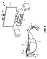
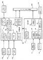
[0033] 図1は、ユーザーの意図に基づいて最適画像を生成するシステム10の一実施形態のコンポーネント例を示すブロック図である。システム10は、ワイヤ6を通じて演算装置4と通信するニアアイ頭部装着ディスプレイ・デバイス2のような、透視ディスプレイ・デバイスを含む。
[0033] FIG. 1 is a block diagram illustrating example components of one embodiment of a
[0034] 他の実施形態では、頭部装着ディスプレイ・デバイス2は、ワイヤレス通信によって演算装置4と通信する。頭部装着ディスプレイ・デバイス2は、一実施形態ではめがねの形状であり、ユーザーがディスプレイを透視しこれによってユーザーの前方にある空間の実際の直接視(actual and direct view)を有することができるように、ユーザーの頭部に着用する。「実際の直接視」という用語の使用は、形成された物体の画像表現を見るのではなく、人間の目で直接実世界の物体を見る能力を指す。例えば、ガラスを通して室内を見ると、ユーザーはその部屋の実際の直接視を有することができ、一方テレビジョンにおいて部屋のビデオを見ることは、その部屋の実際の直接視ではない。頭部装着ディスプレイ・デバイス2のこれ以上の詳細については、以下で説明する。
[0034] In another embodiment, the head mounted
[0035] 一実施形態では、演算装置4は、ユーザーの手首に着用され、頭部装着ディスプレイ・デバイス2を動作させるために用いられる計算パワーの多くを含む。演算装置4は、1つ以上のハブ計算システム12にワイヤレスで通信する(例えば、WiFi、Bluetooth(登録商標)、赤外線、または他のワイヤレス通信手段)。
[0035] In one embodiment, the
[0036] ハブ計算システム12は、コンピューター、ゲーミング・システムまたはコンソール等であってもよい。一実施形態例によれば、ハブ計算システム12は、このハブ計算システム12が、ゲーミング・アプリケーション、ゲーム以外のアプリケーション等のようなアプリケーションを実行するために用いることができるように、ハードウェア・コンポーネントおよび/またはソフトウェア・コンポーネントを含むことができる。一実施形態では、ハブ計算システム12は、本明細書において記載するプロセスを実行するためにプロセッサー読み取り可能記憶デバイスに格納されている命令を実行することができる、標準的なプロセッサー、特殊プロセッサー、マイクロプロセッサー等のようなプロセッサーを含むことができる。
[0036] The
[0037] 更に、ハブ計算システム12は、キャプチャー・デバイス20Aおよび20Bのような、1つ以上のキャプチャー・デバイスも含む。他の実施形態では、2つよりも多いまたは少ないキャプチャー・デバイスを用いることができる。一実施態様例では、キャプチャー・デバイス20Aおよび20Bは、部屋の異なる部分を取り込むように、異なる方向に照準を向けられている。尚、2つのキャプチャー・デバイスの視野が多少重複し、ハブ計算システム12が、これらのキャプチャー・デバイスの視野が互いにどのように関係するのか把握できるようにすると有利であると考えられる。このように、複数のキャプチャー・デバイスを用いて、部屋全体(または他の空間)を見る(view)ことができる。あるいは、動作中に1つのキャプチャー・デバイスをパンニングすることができ、関連する空間全体が経時的にそのキャプチャー・デバイスによって見ることができるような場合、1つのキャプチャー・デバイスを用いることもできる。重複しないキャプチャー・デバイスであっても、ユーザーが着用している頭部装着ディスプレイの位置というような、他の既知の点に関して視野を判定することができる。
[0037] In addition, the
[0038] キャプチャー・デバイス20Aおよび20Bは、例えば、1人以上のユーザーおよび周囲の空間を視覚的に監視するカメラとするとよく、周囲の空間の構造だけでなく、1人以上のユーザーによって行われるジェスチャーおよび/または動きも取り込み、分析し、そして追跡して、アプリケーションにおいて1つ以上の制御または動作(action)を実行する、および/またはアバターまたは画面上のキャラクターを動画化することができるとよい。
[0038] The
[0039] ハブ計算システム12は、ゲームまたはアプリケーションの映像部分を供給することができるテレビジョン、モニター、高品位テレビジョン(HDTV)等のようなオーディオビジュアル・デバイス16に接続されていてもよい。例えば、ハブ計算システム12は、ゲーム・アプリケーション、ゲーム以外のアプリケーション等と関連するオーディオビジュアル信号を供給することができる、グラフィクス・カードのようなビデオ・アダプター、および/またはサウンド・カードのようなオーディオ・アダプターを含んでもよい。オーディオビジュアル・デバイス16は、ハブ計算システム12からオーディオビジュアル信号を受け取ることができ、次いでこのオーディオビジュアル信号と関連するゲームまたはアプリケーションの映像部分および/またはオーディオを出力することができる。一実施形態によれば、オーディオビジュアル・デバイス16は、例えば、S−Videoケーブル、同軸ケーブル、HDMI(登録商標)ケーブル、DVIケーブル、VGAケーブル、コンポーネント・ビデオ・ケーブル、RCAケーブル等によって、ハブ計算システム12に接続されるとよい。一例では、オーディオビジュアル・デバイス16は内部スピーカを含む。他の実施形態では、オーディオビジュアル・デバイス16、別個のステレオ、またはハブ計算システム12を外部スピーカ22に接続する。
[0039] The
[0040] ハブ計算デバイス10は、キャプチャー・デバイス20Aおよび20Bと共に、人間(または他のタイプの)ターゲットを認識、分析、および/または追跡するために用いることができる。例えば、キャプチャー・デバイス20Aおよび20Bを用いて、頭部装着ディスプレイ・デバイス2を着用しているユーザーを追跡することができ、ユーザーのジェスチャーおよび/または動きを取り込んでアバターまたは画面上のキャラクターを動画化することができ、および/またはハブ計算システム12が実行しているアプリケーションに作用するために用いることができる制御として、ユーザーのジェスチャーおよび/または動きを解釈することもできる。
[0040] The
[0041] 開示する技術の一実施形態では、以下で詳細に論ずるように、システム10は、ユーザーの環境において1つ以上の物体と相互作用するユーザーの意図を判定することに基づいて、ユーザーに最適な画像を生成する。この最適画像は、ユーザーが相互作用しようとする物体の強調した外観、ユーザーが相互作用しようとしない物体の目立たなくした外観、または双方を含むことができる。最適画像は、頭部装着ディスプレイ・デバイス2を介して、ユーザーに表示される。
[0041] In one embodiment of the disclosed technology, as discussed in detail below, the
[0042] 図2は、頭部装着ディスプレイ・デバイス2の一部の上面図を示し、弦102および鼻ブリッジ104を含むフレームの一部を含む。頭部装着ディスプレイ・デバイス2の右側だけが図示されている。鼻ブリッジ104の中には、以下で説明するように、音を記録しそのオーディオ・データーを演算装置4に送信するマイクロフォン110が組み込まれている。頭部装着ディスプレイ・デバイス2の前方には、ビデオおよび静止画像を取り込むことができるビデオ・カメラ113に面する部屋がある。これらの画像は、以下で説明するように、演算装置4に送信される。
FIG. 2 shows a top view of a portion of the head mounted
[0043] 頭部装着ディスプレイ・デバイス2のフレームの一部が、ディスプレイ(1つ以上の光学エレメントを含む)を包囲する。頭部装着ディスプレイ・デバイス2のコンポーネントを示すために、ディスプレイを包囲するフレームの一部は図示されていない。一実施形態では、このディスプレイは、導光光エレメント112、不透明フィルター114、透視レンズ116、および透視レンズ118を含む。一実施形態では、不透明フィルター114は、透視レンズ116の後ろにあってこれと整列されており、導光光学エレメント112は不透明フィルター114の後ろにあってこれと整列されており、透視レンズ118は、導光光学エレメント112の後ろにあってこれと整列されている。透視レンズ116および118は、めがねに用いられる標準的なレンズであり、いずれの処方(prescription)に合わせてでも(処方がない場合も含む)作成することができる。一実施形態では、透視レンズ116および118は、可変処方レンズと置き換えることができる。実施形態の中には、頭部装着ディスプレイ・デバイス2が1つの透視レンズしか含まない場合、または透視レンズを含まない場合もある。他の代替案では、処方レンズは導光光学エレメント112の内側に入ることができる。不透明フィルター114は、自然光(画素毎または均一にのいずれか)を排除して、仮想形像のコントラストを強調する。導光光学エレメント112は、人工光を目まで伝える。不透明フィルター114および導光光学エレメント112のこれ以上の詳細については、以下で説明する。代替実施形態では、不透明フィルター114を利用しなくてもよい。
[0043] A portion of the frame of the head mounted
[0044] 弦102には、またはその内側には、画像ソースが装着されており、(一実施形態では)仮想画像を投射するマイクロ・ディスプレイ・アセンブリー120と、マイクロ・ディスプレイ120からの画像を導光光学エレメント112に導く連ス122とを含む。一実施形態では、レンズ122は、平行化レンズである。
[0044] An image source is mounted on or inside the
[0045] 制御回路136は、頭部装着ディスプレイ・デバイス2の他のコンポーネントをサポートする種々の電子回路を設ける。制御回路136のこれ以上の詳細については、以下で図3に関して示すことにする。弦102の内側には、イヤホン130、慣性センサー132、および温度センサー138があり、またはこれらは弦102に取り付けられる。一実施形態では、慣性センサー132は、三軸磁力計132A、三軸ジャイロ132B、および三軸加速度計132C(図3参照)を含む。慣性センサーは、頭部装着ディスプレイ・デバイス2の位置、向き、急激な加速を検知するためにある。
The
[0046] マイクロ・ディスプレイ120は、レンズ122を通して画像を投射する。マイクロ・ディスプレイ120を実現するために用いることができる、異なる画像生成技術がある。例えば、マイクロ・ディスプレイ120は、透過型投射技術を用いて実現することができる。この場合、光源は、白色光によるバックライトを受ける、光学的にアクティブな材料によって変調される。これらの技術は、通常、強力なバックライトおよび高い光エネルギ密度を有するLCD型ディスプレイを用いて実現されている。また、マイクロ・ディスプレイ120は、反射技術を用いて実現することもできる。この場合、外部光が反射され光学的にアクティブな材料によって変調される。技術に応じて、白色光源またはRGB光源のいずれかによって、照明を前方に発する。ディジタル光処理(DLP)、シリコン上液晶(LCOS)、およびQualcomm, inc.(クアルコム社)からのMirasol(登録商標)表示技術は全て、反射技術の例である。これらの技術は、殆どのエネルギーが変調構造(modulated structure)から遠ざかるように反射されるので効率的であり、本明細書において記載するシステムにおいて用いることができる。加えて、マイクロ・ディスプレイ120は、発光技術(emissive technology)を用いて実現することもできる。この場合、ディスプレイによって光を生成する。例えば、Microvision, Inc.(マイクロビジョン社)からのPicoP(登録商標)は、レーザー信号を、マイクロ・ミラー制御(steering)によって、透過エレメントとして作用する小さな画面上に出すか、または直接目に向けて放つ(例えば、レーザー)。
The
[0047] 導光光学エレメント112は、マイクロ・ディスプレイ120からの光を透過させて、頭部装着ディスプレイ・デバイス2を着用しているユーザーの目140に向かわせる。また、導光光学エレメント112は、矢印142によって示されるように、頭部装着ディスプレイ・デバイス2の前方からの光も、導光光学エレメント112を介して目140に向けて透過させることができ、これによってユーザーがマイクロ・ディスプレイ120からの仮想画像を受け取ることに加えて、頭部装着ディスプレイ・デバイス2の前方にある空間の実際の直接視を有することを可能にする。つまり、導光光学エレメント112の壁は、透けて見える(see-through)。導光光学エレメント112は、第1反射面124(例えば、ミラーまたは他の表面)を含む。マイクロ・ディスプレイ120からの光は、レンズ・システム122を通過して、反射面124に入射する。反射面124は、マイクロ・ディスプレイ120からの入射光を反射して、導光光学エレメント112を構成する平面基板の内側に、内反射によって光が取り込まれるようにする。この基板の表面を数回反射した後、取り込まれた光波は、選択的反射面126のアレイに到達する。尚、図面が混みすぎるのを防止するために、5つの表面の内1つだけに126を付していることを注記しておく。反射面126は、基板の外側からこれらの反射面上に入射した光波を、ユーザーの目140に結合する。異なる光線が進行し異なる角度で基板の内側から反射する(bounce off)と、異なる光線が種々の反射面126に異なる角度で衝突する。したがって、異なる光線が、反射面の異なる1つ1つによって、基板から反射される。どの光線をどの表面126によって基板から反射させるかという選択は、表面126の適した角度を選択することによって管理される。一実施形態では、各目がそれ自体の導光光学エレメント112を有する。頭部装着ディスプレイ・デバイスが2つの導光光学エレメントを有するとき、各目は、それ自体のマイクロ・ディスプレイ120を有し、双方の目で同じ画像を表示すること、または2つの目で異なる画像を表示することができる。他の実施形態では、光を双方の目に反射させる1つの導光光学エレメントを設けることができる。
The light guide
[0048] 不透明フィルター114は、導光光学エレメント112と整列されており、選択的に自然光が、均一にまたは画素毎に、導光光学エレメント112を通過するのを遮断する。一実施形態では、不透明フィルターは、透視LCDパネル、エレクトロクロミック・フィルム、または不透明フィルターとして役割を果たすことができる同様のデバイスとすることができる。このような透視LCDパネルは、従来のLCDから基板、バックライト、およびディフューザーの種々の層を除去することによって得ることができる。LCDパネルは、光に液晶を通過させる1つ以上の光透過性LCDチップを含むことができる。このようなチップは、例えば、LCDプロジェクターにおいて使用されている。
[0048] The
[0049] 不透明フィルター114は、密集した画素の格子を含むことができ、各画素の光透過度は、最低透過度および最高透過度の間で個々に制御可能である。透過度の範囲は0〜100%が理想的であるが、これよりも限られた範囲でも容認可能である。一例として、偏光フィルターが2つしかないモノクロームLCDパネルでも、画素当たり約50%から90%の不透明度範囲をLCDの分解能まで与えるには十分である。最低の50%において、レンズは多少着色した外観を有するが、許容可能である。100%の透過度は、完全に透明なレンズを表す。「アルファ」スケールを0〜100%まで定めることができ、0%では光を通過させず、100%では光を通過させる。アルファの値は、以下で説明する不透明フィルター制御回路224によって、画素毎に設定することができる。
[0050] 実世界物体の代用にz−バッファリングを行った後、レンダリング・パイプラインからアルファ値のマスクを用いることができる。本システムは、拡張現実表示のために場面をレンダリングするとき、どの実世界物体がどの仮想物体の前にあるか注意を払う。仮想物体が実世界物体の前にある場合、仮想物体が遮るエリアを不透明にしなければならない。仮想物体が(仮想的に)実世界物体の後ろにある場合、ユーザーが実際の光のその対応するエリア(1画素以上のサイズ)の実世界の物体だけを見るように、その画素に対するあらゆる色だけでなく不透明性もオフにする。遮蔽(coverage)は、画素毎であるので、本システムは、仮想物体の一部が実世界の物体の前にある場合、仮想物体の一部が実世界の物体の後ろにある場合、そして仮想物体の一部が実世界の物体と同じ位置にある場合も扱うことができる。0%から100%まで不透明性を可変にすることができる低コスト、低パワーおよび軽量のディスプレイが、この使用には最も望ましい。更に、不透明フィルターは、カラーLCDによって、または有機LEDのような他のディスプレイによって、カラーでレンダリングし、広い視野を設けることができる。不透明フィルターについてのこれ以上の詳細は、"Opacity Filter For See-Through Mounted Display"(透視装着ディスプレイ用不透明フィルター)と題し、2010年9月21日に出願された米国特許出願第12/887,426号において示されている。この出願をここで引用したことにより、その内容全体が本願にも含まれることとする。
[0049] The
[0050] After performing z-buffering on behalf of real-world objects, an alpha value mask can be used from the rendering pipeline. The system pays attention to which real world objects are in front of which virtual objects when rendering a scene for augmented reality display. If the virtual object is in front of a real-world object, the area covered by the virtual object must be opaque. If the virtual object is (virtually) behind a real-world object, any color for that pixel so that the user sees only the real-world object in its corresponding area of real light (one or more pixels) Not only opacity is turned off. Since the coverage is per pixel, the system can be used when a part of a virtual object is in front of a real world object, a part of a virtual object is behind a real world object, and a virtual A case where a part of an object is at the same position as an object in the real world can also be handled. Low cost, low power and lightweight displays that can vary opacity from 0% to 100% are most desirable for this use. Furthermore, the opaque filter can be rendered in color by a color LCD or by other displays such as organic LEDs to provide a wide field of view. Further details about the opacity filter are described in US patent application Ser. No. 12 / 887,426, filed Sep. 21, 2010, entitled “Opacity Filter For See-Through Mounted Display”. It is shown in the issue. By quoting this application here, the entire contents thereof are also included in the present application.
[0051] LCDのような不透明フィルターは、一般に、本明細書において記載するような透視レンズには用いられなかった。何故なら、このように目に近い距離では、焦点がはずれる可能性があるからである。しかしながら、場合によっては、この結果が望ましいこともあり得る。ユーザーは、焦点が合うように設計された、追加カラーを用いた通常のHMDディスプレイによって、生き生きとしたカラー・グラフィクスによる仮想画像を見る。LCDパネルは、曖昧な黒い境界があらゆる仮想コンテンツを包囲するように、このディスプレイの「後ろに」配され、これを所望通りに不透明にする。本システムは、自然なぼけという欠点を変換して、アンチエリアシングおよび帯域幅削減という特徴を功利的に獲得する。これらは、低解像度で焦点がはずれた画像を用いることの当然の結果である。ディジタル的にサンプリングした画像には、効果的なスムージングがある。あらゆるディジタル画像にはエリアシングが生じ、サンプリングの離散的性質のために、自然なアナログおよび連続信号と比較すると、光の波長の周りで誤差が生ずる。スムージングが意味するのは、理想的なアナログ信号に視覚的に近づけることである。低解像度にしたことによって失われた情報は復元されないが、結果的に生ずる誤差は、さほど目立たない。 [0051] Opaque filters such as LCDs were generally not used in fluoroscopic lenses as described herein. This is because there is a possibility of defocusing at such a distance close to the eyes. However, in some cases this result may be desirable. A user views a virtual image with vibrant color graphics through a normal HMD display with additional colors designed to be in focus. The LCD panel is placed “behind” this display so that an obscure black border surrounds any virtual content, making it opaque as desired. The system takes advantage of the anti-aliasing and bandwidth reduction features by translating the drawbacks of natural blur. These are the natural consequences of using low resolution and defocused images. Digitally sampled images have effective smoothing. Every digital image is aliased, and due to the discrete nature of sampling, there is an error around the wavelength of light when compared to natural analog and continuous signals. Smoothing means visually approaching an ideal analog signal. Information lost due to the low resolution is not restored, but the resulting error is less noticeable.
[0052] 一実施形態では、ディスプレイおよび不透明フィルターを同時にレンダリングし、角度−オフセットの問題を補償するために空間におけるユーザーの正確な位置に合わせてディスプレイおよび不透明フィルターを較正する。視野の両端における正しい画像オフセットを計算するために、目追跡を採用することができる。実施形態の中には、不透明フィルターにおいて、不透明量の時間的または空間的衰退(fade)を用いることができる。同様に、仮想画像の時間的または空間的衰退も用いることができる。1つの手法では、不透明フィルターの不透明量の時間的衰退は、仮想画像の時間的衰退に対応する。他の手法では、不透明フィルターの不透明量の空間的衰退が、仮想画像の空間的衰退に対応する。 [0052] In one embodiment, the display and opacity filter are rendered simultaneously, and the display and opacity filter are calibrated to the user's exact location in space to compensate for angle-offset issues. Eye tracking can be employed to calculate the correct image offset at both ends of the field of view. In some embodiments, an opaque amount of temporal or spatial fade can be used in an opacity filter. Similarly, temporal or spatial decay of virtual images can be used. In one approach, the temporal decay of the opacity amount of the opacity filter corresponds to the temporal decay of the virtual image. In another approach, the spatial decay of the opacity amount of the opacity filter corresponds to the spatial decay of the virtual image.
[0053] 1つの手法では、特定したユーザーの目の位置の視界から、仮想画像の後ろに来る不透明フィルターの画素には、不透明性を増大して与える。このように、仮想画像の後ろに来る画素を暗くして、実世界場面の対応部分からの光が、ユーザーの目に達しないように遮断する。これによって、仮想画像が現実的となり、最大範囲の色および輝度を表すことが可能になる。更に、拡張現実エミッタによる電力消費が低減する。何故なら、仮想画像は低い輝度で供給されるからである。不透明フィルターがないと、仮想画像が区別でき透明にならないようにするためには、実世界場面の対応する部分よりも明るい十分高い輝度で、仮想画像を供給しなければならない。一般に、不透明フィルターの画素を暗くする際、仮想画像の閉じた周囲を辿る画素を、その周囲の内部にある画素と共に暗くする。この周囲の直ぐ外側にありこの周囲を包囲する画素も暗くなるように(同じレベルの暗さ、または周囲の内部にある画素よりは暗くない)、多少の重複が得られることが望ましいこともあり得る。周囲の直ぐ外側にあるこれらの重複する画素は、周囲の内側における暗さから周囲の外側における最大量の不透明までの衰退(例えば、徐々に変わる不透明性の推移)を規定することができる。 In one method, the opacity of the opacity filter pixel behind the virtual image is increased and given opacity from the field of view of the identified user's eye position. In this way, the pixels behind the virtual image are darkened to block light from corresponding parts of the real world scene from reaching the user's eyes. This makes the virtual image realistic and allows the maximum range of colors and brightness to be represented. Furthermore, power consumption by the augmented reality emitter is reduced. This is because the virtual image is supplied with low brightness. Without the opacity filter, the virtual image must be supplied with a sufficiently high brightness that is brighter than the corresponding part of the real world scene, so that the virtual image is not distinguishable and transparent. In general, when the pixels of the opaque filter are darkened, the pixels that follow the closed periphery of the virtual image are darkened together with the pixels inside the periphery. It may be desirable to have some overlap so that the pixels that are just outside this perimeter and surround the perimeter are also dark (same level of darkness or less dark than the pixels inside the perimeter) obtain. These overlapping pixels just outside the perimeter can define a decay (eg, a gradual change in opacity) from darkness inside the perimeter to the maximum amount of opacity outside the perimeter.
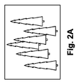
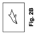
[0054] 不透明フィルターの動作の一例を挙げるために、図2Aは、頭部装着ディスプレイ・デバイス2を介して見ているユーザーの目に見ることができる森の実世界場面例を示す。図2Bは、仮想画像を示すが、この場合いるかである。図2Cは、図2Bの仮想画像の形状に基づく不透明フィルターの外形例を示す。不透明フィルターは、不透明性が増大した暗化領域を規定し、この中にいるかをレンダリングする。不透明性の増大とは、一般に、白黒方式における異なるグレー・レベルへの暗化(darkening)、またはカラー方式における異なるカラー・レベルへの暗化を含む、画素の暗化を指す。モノクローム方式では異なるグレー・レベル(または黒)への暗化、またはカラー方式では異なるカラー・レベルへの暗化を用いることができる。図2Dは、ユーザーによって見られる画像例を示す。これは、いるかの仮想画像をユーザーの視界に投射し、不透明フィルターを用いて、いるかの仮想画像の位置に対応する画素に対する光を除去した結果である。見て分かるように、背景は、いるかを通して見ることはできない。比較の目的のために、図2Eは、不透明フィルターを用いない、仮想画像の実画像への挿入を示す。見て分かるように、実背景は、いるかの仮想画像を通して見ることができる。
[0054] To give an example of the operation of the opacity filter, FIG. 2A shows an example of a real world scene of a forest that can be seen by a user viewing through a head mounted
[0055] また、頭部装着ディスプレイ・デバイス2は、ユーザーの目の位置を追跡するシステムも含む。以下で説明するが、このシステムは、ユーザーの視野を判定できるようにユーザーの位置および向きを追跡する。しかしながら、人間は、彼らの前にあるあらゆるものを認知する訳ではない。逆に、ユーザーの目は環境の内一部(subset)に向けられる。したがって、一実施形態では、本システムは、ユーザーの視野の測定を厳密に行う(refine)ために、ユーザーの目の位置を追跡する技術を含む。例えば、頭部装着ディスプレイ・デバイス2は、目追跡アセンブリー134(図2参照)を含む。目追跡アセンブリー134は、目追跡照明デバイス134A、および目追跡カメラ134B(図3参照)を含む。一実施形態では、目追跡照明源134Aは、IR光を目に向けて放出する1つ以上の赤外線(IR)発光器を含む。目追跡カメラ134Bは、反射したIR光を検知する1つ以上のカメラを含む。瞳の位置は、角膜の反射を検出する既知の撮像技法によって特定することができる。例えば、2008年7月22日にKranz et al.,に発行された"Head Mounted Eye Tracking and Display System"(頭部装着目追跡および表示システム)と題する米国特許第7,401,920号を参照のこと。この特許をここで引用したことにより、その内容全体が本願にも含まれるものとする。このような技法は、追跡カメラに対する目の中心の位置を突き止めることができる。一般に、目の追跡には、目の画像を得て、コンピューター映像技法を用いて眼窩内部における瞳の位置を判定する必要がある。一実施形態では、1つの目の位置を追跡すれば十分である。何故なら、目は通常一緒に動くからである。しかしながら、各目を別々に追跡することも可能である。あるいは、目追跡カメラは、照明源を用いてまたは用いずに、いずれかの目の動きに基づく画像を用いて位置を追跡する、代わりの形態の追跡カメラであってもよい。
[0055] The head mounted
[0056] 一実施形態では、本システムは、頭部装着ディスプレイ・デバイス2のレンズの角毎に1つずつのIR LEDおよびIR光検出器があるように、矩形配列とした4つのIRLEDおよび4つのIR光検出器を用いる。LEDからの光は目で反射する。4つのIR光検出器の各々において検出された赤外線光量によって、瞳の方向を判定する。即ち、目における白および黒の量から、その特定の光検出器に対して目から反射する光の量を判定する。こうして、光検出器は白目または黒目の量を測定する。4つのサンプルから、本システムは目の方向を判定することができる。
[0056] In one embodiment, the system includes four IRLEDs and 4 in a rectangular array such that there is one IR LED and IR photodetector for each corner of the head mounted
[0057] 他の代替案は、先に論じたように、4つの赤外線LEDを用いるが、頭部装着ディスプレイ・デバイス2のレンズの側には1つの赤外線CCDしか用いないことである。このCCDは、小型のミラーおよび/またはレンズ(魚眼)を用い、このCCDがめがねのフレームから見ることができる目の75%までを撮像することができるようにしている。次いで、このCCDは、先に論じたのと全く同じように、画像を検知し、コンピューター映像を用いて画像を発見する。つまり、図2は1つのIR発光器を有する1つのアセンブリーを示すが、図2の構造は、4つのIR送信機および/または4つのIRセンサーを有するように調節することができる。4つよりも多いまたは少ないIR送信機および/またはIRセンサーを用いることもできる。
[0057] Another alternative is to use four infrared LEDs as discussed above, but only one infrared CCD on the lens side of the head mounted
[0058] 目の方向を追跡する他の実施形態は、電荷追跡に基づく。この概念は、網膜が測定可能な正の電荷を保持し、角膜は負の電荷を有するという観察に基づく。目が動き回る間に電位を検出するために、ユーザーの耳にセンサーを装着し(イヤホン130の近く)、これらのセンサーは、目が何をしているのかリアル・タイムで効果的に読み出す。めがねの内部に装着された小型カメラというような、目を追跡するための他の実施形態を用いることもできる。 [0058] Another embodiment for tracking the direction of the eye is based on charge tracking. This concept is based on the observation that the retina retains a measurable positive charge and the cornea has a negative charge. Sensors are worn on the user's ears (near the earphones 130) to detect the potential as the eyes move around, and these sensors effectively read out what the eyes are doing in real time. Other embodiments for tracking the eyes can be used, such as a small camera mounted inside the glasses.
[0059] 尚、頭部装着ディスプレイ・デバイス2上には、1つ以上の追加の検出器を含めてもよいことは言うまでもない。このような検出器には、限定ではなく、SONAR、LIDAR、構造化光、および/またはデバイスを着用している者が見ているかもしれない情報を検出するように位置付けられた飛行時間距離検出器を含むことができる。
[0059] Needless to say, one or more additional detectors may be included on the head-mounted
[0060] 図2は、頭部装着ディスプレイ・デバイス2の半分のみを示す。頭部装着ディスプレイ・デバイス全体では、もう1組の透視レンズ、他の不透明フィルター、他の導光光学エレメント、他のマイクロ・ディスプレイ136、他のレンズ・システム122、部屋に面するカメラ、目追跡アセンブリー、マイクロ・ディスプレイ、イヤホン、および温度センサーを含む。頭部装着ディスプレイ・デバイス2のこれ以上の詳細は、"Fusing Virtual Content Into Real Content"(仮想コンテンツの実コンテンツへの融合)と題し2010年10月15日に出願された米国特許出願第12/905,952号において示されている。この特許出願をここで引用したことにより、その内容全体が本願にも含まれるものとする。
FIG. 2 shows only half of the head mounted
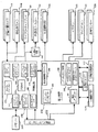
[0061] 図3は、頭部装着ディスプレイ・デバイス2の種々のコンポーネントを示すブロック図である。図4は、演算装置4の種々のコンポーネントを説明するブロック図である。頭部装着ディスプレイ・デバイス2は、そのコンポーネントが図3に示されており、ユーザーの環境において1つ以上の物体と相互作用するユーザーの意図を判定することに基づいて、ユーザーに最適画像を表示するために用いられる。加えて、図3の頭部装着ディスプレイ・デバイスのコンポーネントは、種々の状態を追跡する多くのセンサーを含む。頭部装着ディスプレイ・デバイス2は、仮想画像についての命令を演算装置4から受け、逆にセンサー情報を演算装置4に提供する。演算装置4は、そのコンポーネントが図3に示されており、頭部装着ディスプレイ2から、そしてハブ計算デバイス12(図1参照)からもセンサー情報を受け取る。この情報に基づいて、演算装置4は、仮想画像をどこにそしていつユーザーに供給すべきか判断し、それに応じて命令を図3の頭部装着ディスプレイ・デバイスに送る。
FIG. 3 is a block diagram illustrating various components of the head mounted
[0062] 尚、図3のコンポーネントの一部(例えば、後部境対面カメラ113、目追跡カメラ134B、マイクロ・ディスプレイ120、不透明フィルター114、目追跡照明134A、イヤホン130、および温度センサー138)は、これらのデバイスが各々2つずつあり、1つが頭部装着ディスプレイ・デバイス2の左側、そして1つが右側にあることを示すために、影を付けて(in shadow)図示されていることを注記しておく。図3は、電力管理回路202と通信する制御回路200を示す。制御回路200は、プロセッサー210、メモリー214(例えば、D−RAM)と通信可能なメモリー・コントローラー212、カメラ・インターフェース216、カメラ・バッファー218、ディスプレイ・ドライバー220、ディスプレイ・フォーマッター222、タイミング・ジェネレーター226、ディスプレイ出力インターフェース228、およびディスプレイ入力インターフェース230を含む。一実施形態では、制御回路220のコンポーネントは全て、互いに、専用線または1つ以上のバスを介して通信する。他の実施形態では、制御回路200のコンポーネントは全て、プロセッサー210と通信する。カメラ・インターフェース216は、2つの部屋対面カメラ113にインターフェースを設け、部屋対面カメラから受け取った画像をカメラ・バッファー218に格納する。ディスプレイ・ドライバー220は、マイクロ・ディスプレイ120を駆動する。ディスプレイ・フォーマッター222は、マイクロ・ディスプレイ120上に表示されている仮想画像についての情報を、不透明フィルター114を制御する不透明制御回路224に提供する。タイミング・ジェネレーター226は、システムにタイミング・データーを供給するために用いられる。ディスプレイ出力インターフェース228は、部屋対面カメラ113から演算装置4に画像を供給するためのバッファーである。ディスプレイ入力230は、マイクロ・ディスプレイ120に表示しようとする仮想画像のような画像を受け取るためのバッファーである。ディスプレイ出力228およびディスプレイ入力230は、演算装置4に対するインターフェースである帯域インターフェース232と通信する。
[0062] It should be noted that some of the components in FIG. 3 (for example, the rear
[0063] 電力管理回路202は、電圧レギュレーター234、目追跡照明ドライバー236、オーディオDACおよび増幅器238、マイクロフォン・プリアンプおよびオーディオADC240、温度センサー・インターフェース242、ならびにクロック・ジェネレーター244を含む。電圧レギュレーター234は、演算装置4から帯域インターフェース232を介して電力を受け、その電力を頭部装着ディスプレイ・デバイス2の他のコンポーネントに供給する。目追跡照明ドライバー236は、前述のように、IR光源を目追跡照明134Aのために設ける。オーディオDACおよび増幅器238は、オーディオ情報をイヤホン130から受け取る。マイクロフォン・プリアンプおよびオーディオADC240は、マイクロフォン110に対するインターフェースを設ける。温度センサー・インターフェース242は、温度センサー138に対するインターフェースである。また、電力管理ユニット202は、電力を供給し、三軸磁力計132A、三軸ジャイロ132B、および三軸加速度計132Cからは逆にデーターを受け取る。
[0063] The
[0064] 図4は、演算装置4の種々のコンポーネントを説明するブロック図である。図4は、電力管理回路306と通信する制御回路304を示す。制御回路304は、中央演算装置(CPU)320、グラフィクス処理ユニット(GPU)322、キャッシュ324、RAM326、メモリー330(例えば、D−RAM)と通信するメモリー制御部328、フラッシュ・メモリー334(または他のタイプの不揮発性ストレージ)と通信するフラッシュ・メモリー・コントローラー332、帯域インターフェース302および帯域インターフェース232を介して頭部装着ディスプレイ・デバイス2と通信するディスプレイ出力バッファー326、帯域インターフェース302および帯域インターフェース232を介して頭部装着ディスプレイ・デバイス2と通信するディスプレイ入力バッファー338、マイクロフォンに接続するために外部マイクロフォン・コネクター342と通信可能なマイクロフォン・インターフェース340、ワイヤレス通信デバイス346に接続するためのPCIエクスプレス・インターフェース、ならびにUSBポート(1つまたは複数)348を含む。一実施形態では、ワイヤレス通信コンポーネント346は、Wi−Fi対応通信デバイス、BlueTooth(登録商標)通信デバイス、赤外線通信デバイス等を含むことができる。USBポートは、演算装置4をハブ計算デバイス12にドッキングして、データーまたはソフトウェアを演算装置4にロードするため、および演算装置4を充電するために用いることができる。一実施形態では、CPU320およびGPU322は、どこに、いつ、そしてどのように仮想画像をユーザーの視野に挿入すべきか判断するための主要な機械(workhorse)である。これ以上の詳細は、以下で示す。
FIG. 4 is a block diagram illustrating various components of the
[0065] 電力管理回路306は、クロック・ジェネレーター360、アナログ/ディジタル変換器362、バッテリー充電器364、電圧レギュレーター366、頭部装着ディスプレイ電源376、および温度センサー374(演算装置4の手首バンド上に配置されている)と通信可能な温度センサー・インターフェース372を含む。アナログ/ディジタル変換器362が、AC供給電力を受け、本システムのためにDC供給電力を発電するために、充電ジャック370に接続されている。電圧レギュレーター366は、本システムに電力を供給するために、バッテリー368と通信する。バッテリー充電器364は、充電ジャック370から受電すると、バッテリー368を充電する(電圧レギュレーター366を介して)ために用いられる。HMD電力インターフェース376は、電力を頭部装着ディスプレイ・デバイス2に供給する。
The
[0066] 前述のシステムは、仮想画像が実世界物体の映像(view)と置き換わるように、ユーザーの視野内に仮想画像を挿入するように構成される。あるいは、仮想画像は、実世界物体の画像を置き換えることなく、挿入することもできる。種々の実施形態において、置き換えられる物体または画像が挿入されようとしている環境に基づいて、しかるべき向き、サイズ、および形状に一致するように、仮想画像を調節する。加えて、仮想画像は、反射(reflectivity)および影を含むように調節することができる。一実施形態では、頭部装着ディスプレイ・デバイス12、演算装置4、およびハブ計算デバイス12は、一緒に動作する。これは、これらのデバイスの各々が、どこに、いつ、そしてどのように仮想画像を挿入すべきか判断するためのデーターを得るために用いられるセンサーの一部(subset)を含むからである。一実施形態では、どこに、いつ、そしてどのように仮想画像を挿入すべきか判断する計算は、ハブ計算デバイス12が実行する。他の実施形態では、これらの計算は演算装置4によって実行される。他の実施形態では、これらの計算の一部はハブ計算デバイス12によって実行するが、他の計算は演算装置4によって実行する。他の実施形態では、これらの計算は頭部装着ディスプレイ・デバイス12によって実行することができる。
[0066] The system described above is configured to insert a virtual image into the user's field of view such that the virtual image replaces a view of a real world object. Alternatively, the virtual image can be inserted without replacing the image of the real world object. In various embodiments, the virtual image is adjusted to match the appropriate orientation, size, and shape based on the environment into which the object or image to be replaced is being inserted. In addition, the virtual image can be adjusted to include reflectivity and shadows. In one embodiment, head mounted
[0067] 一実施形態例では、ハブ計算デバイス12は、ユーザーが存在する環境のモデルを作成し、その環境内において動いている種々の物体を追跡する。代替実施形態では、環境において関心のある物体およびユーザーを、他の手段によって判定する。加えて、ハブ計算デバイス12は、頭部装着ディスプレイ・デバイス2の位置および向きを追跡することによって、頭部装着ディスプレイ・デバイス2の視野を追跡する。モデルおよび追跡情報を、ハブ計算デバイス12から演算装置4に供給する。頭部装着ディスプレイ・デバイス2によって得られたセンサー情報を、演算装置4に送信する。すると、演算装置4は、頭部装着ディスプレイ・デバイス2からそれが受け取った追加のセンサー情報を用いて、ユーザーの視野を厳密に定め(refine)、どのように、どこに、そしていつ仮想画像を挿入すべきかについての命令を頭部装着ディスプレイ・デバイス2に供給する。
[0067] In one example embodiment, the
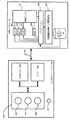
[0068] 図5は、ハブ計算システム12の一実施形態例を、キャプチャー・デバイスと共に示す。一実施形態では、キャプチャー・デバイス20Aおよび20Bは同じ構造であり、したがって、図5はキャプチャー・デバイス20Aのみを示す。一実施形態例によれば、キャプチャー・デバイス20Aは、深度値を含むこともできる深度画像を含む深度情報によって、いずれかの適した技法によってビデオを取り込むように構成するとよい。適した技法には、例えば、飛行時間、構造化光、ステレオ撮像等が含まれる。一実施形態によれば、キャプチャー・デバイス20Aは、深度情報を「Zレイヤー」に編成することができる。即ち、深度カメラからその見通し線に沿って延びるZ軸に対して垂直であるとよいレイヤーに編成することができる。
[0068] FIG. 5 illustrates an example embodiment of the
[0069] 図5に示すように、キャプチャー・デバイス20Aはカメラ・コンポーネント423を含むことができる。一実施形態例によれば、カメラ・コンポーネント423は、場面の深度画像を取り込むことができる深度カメラであってもよく、またはこの深度カメラを含むのでもよい。深度画像は、取り込まれた場面の二次元(2−D)画素エリアを含むことができ、この2−D画素エリアにおける各画素は、カメラからの取り込まれた場面における物体の距離というような深度値を、例えば、センチメートル、ミリメートル等を単位として表すことができる。
[0069] As shown in FIG. 5, the
[0070] カメラ・コンポーネント23は、赤外線(IR)発光コンポーネント425、三次元(3D)カメラ426、および場面の深度画像を取り込むために用いることができるRGB(視覚画像)カメラ428を含むことができる。例えば、飛行時間分析では、キャプチャー・デバイス20AのIR発光コンポーネント425は、キャプチャー・エリアに向けて赤外線光を出すことができ、次いでセンサー(実施形態の中には、図示されていないセンサーを含む場合もある)を用いて、その場面内にある1つ以上のターゲットおよび物体の表面からの後方散乱光を、例えば、3Dカメラ426および/またはRGBカメラ428を用いて検出することができる。実施形態の中には、パルス状赤外線光を用いて、発射光パルスと対応する入射光パルスとの間の時間を測定し、キャプチャー・デバイス20Aから場面内にあるターゲットまたは物体上における特定の場所までの物理的距離を判定するために用いられるようにするとよい場合がある。加えて、他の実施形態例では、発射光波の位相を着信光波の位相と比較して、位相ずれを判定することもできる。次いで、この位相ずれを用いて、キャプチャー・デバイスからターゲットまたは物体上の特定の場所までの物理的距離を判定することができる。
[0070] The camera component 23 can include an infrared (IR) light emitting
[0071] 他の一実施形態例によれば、飛行時間分析を用いて、例えば、散乱光パルス撮像(shuttered light pulse imaging)を含む種々の技法によって、経時的な光の反射ビームの強度を分析することによって、キャプチャー・デバイス20Aからターゲットまたは物体上の特定の位置までの物理的距離を間接的に判定することができる。
[0071] According to another example embodiment, time-of-flight analysis is used to analyze the intensity of the reflected beam of light over time by various techniques including, for example, shuttered light pulse imaging. By doing so, the physical distance from the
[0072] 他の一実施形態例では、キャプチャー・デバイス20Aは、構造化光を用いて深度情報を取り込むことができる。このような分析では、パターン光(即ち、格子パターン、縞パターン、または異なるパターンのような既知のパターンとして表示される光)を、例えば、IR発光コンポーネント424によって、場面に向けて投射する。場面において1つ以上のターゲットまたは物体の表面に衝突したときに、それに応答して、パターンが変形すると考えられる。このようなパターンの変形を、例えば、3Dカメラ426および/またはRGBカメラ428(および/または他のセンサー)によって取り込むことができ、次いで分析して、キャプチャー・デバイスからターゲットまたは物体上における特定の位置までの物理的距離を判定することができる。実施態様の中には、IR発光コンポーネント425をカメラ425および426から変位させて、カメラ425および426からの距離を判定するために三角測量法を用いることができるようにしたものもある。実施態様の中には、キャプチャー・デバイス20Aが、IR光を検知するために専用のIRセンサー、またはIRフィルターを有するセンサーを含む場合もある。
[0072] In another example embodiment, the
[0073] 他の実施形態によれば、キャプチャー・デバイス20Aは、2つ以上の物理的に分離されたカメラを含むことができ、これらが異なる角度から場面を捕らえて、視覚的な立体データーを得て、これを解明することによって深度情報を生成することができる。他のタイプの深度画像センサーも、深度画像を形成するために用いることができる。
[0073] According to other embodiments, the
[0074] 更に、キャプチャー・デバイス20Aは、マイクロフォン430も含むことができる。マイクロフォン430は、音を受けて電気信号に変換することができる変換器またはセンサーを含む。マイクロフォン430は、オーディオ信号を受け取るために用いることもできる。オーディオ信号は、ハブ計算デバイス12によって供給することもできる。
[0074] Further, the
[0075] 一実施形態例では、キャプチャー・デバイス20Aは、更に、撮像カメラ・コンポーネント423と通信することができるプロセッサー432も含むことができる。プロセッサー432は、標準的なプロセッサー、特殊プロセッサー、マイクロプロセッサー等を含むことができ、例えば、深度画像を受け取る命令、しかるべきデーター・フォーマット(例えば、フレーム)を生成する命令、およびデーターをハブ計算デバイス12に送信する命令を含む命令を実行することができる。
[0075] In one example embodiment, the
[0076] キャプチャー・デバイス20Aは、更に、プロセッサー432が実行する命令、3−Dカメラおよび/またはRGBカメラによって取り込まれた画像または画像のフレーム、あるいは他の適した情報、画像等であればいずれでも格納することができるメモリー434も含むことができる。一実施形態例によれば、メモリー434は、ランダム・アクセス・メモリー(RAM)、リード・オンリー・メモリー(ROM)、キャッシュ、フラッシュ・メモリー、ハード・ディスク、または他の適した記憶コンポーネントであればいずれでも含むことができる。図5に示すように、一実施形態では、メモリー434は、画像キャプチャー・コンポーネント423およびプロセッサー432と通信する別個のコンポーネントであってもよい。他の実施形態によれば、メモリー434をプロセッサー432および/または画像キャプチャー・コンポーネント422に統合してもよい。
[0076] The
[0077] キャプチャー・デバイス20Aおよび20Bは、通信リンク436を介して、ハブ計算デバイス12と通信することができる。通信リンク436は、例えば、USB接続、Firewire接続、イーサネット(登録商標)・ケーブル接続等を含む有線接続、および/またはワイヤレス802.1b、g、a、またはn接続というようなワイヤレス接続とすることができる。一実施形態によれば、ハブ計算デバイス12は、クロックをキャプチャー・デバイス20Aに供給することができる。このクロックは、例えば、通信リンク436を介して場面を取り込むときを決定するために用いることができる。加えて、キャプチャー・デバイス20Aは、例えば、3−Dカメラ426および/またはRGBカメラ428によって取り込まれた深度情報ならびに視覚(例えば、RGB)画像をハブ計算デバイス12に、通信リンク436を介して供給する。一実施形態では、深度画像および視覚画像は、毎秒30フレームで送られる。しかしながら、他のフレーム・レートも用いることができる。次いで、ハブ計算デバイス12はモデルを作成し、このモデル、深度情報、および取り込まれた画像を用いて、例えば、ゲームまたはワード・プロセッサーのようなアプリケーションを制御すること、および/またはアバターまたは画面上のキャラクターを動画化することができる。
[0077]
[0078] ハブ計算システム12は、深度画像処理および骨格追跡モジュール450を含む。このモジュール450は、深度画像を用いて、キャプチャー・デバイス20Aの深度カメラ機能によって検出可能な1人以上の人を追跡する。深度画像処理および骨格追跡モジュール450は、追跡情報をアプリケーション452に提供する。アプリケーション452は、ビデオ・ゲーム、生産性アプリケーション、通信アプリケーション、または他のソフトウェア・アプリケーション等とすることができる。また、オーディオ・データーおよびビジュアル画像データーも、アプリケーション452および深度画像処理および骨格追跡モジュール450に供給する。アプリケーション452は、追跡情報、オーディオ・データー、およびビジュアル画像データーを認識エンジン454に供給する。他の実施形態では、認識エンジン454は、追跡情報を直接深度画像処理および骨格追跡モジュール450から受け取り、オーディオ・データーおよびビジュアル画像データーを直接キャプチャー・デバイス20Aおよび20Bから受け取る。
[0078] The
[0079] 認識エンジン454は、フィルター460、462、464、...、466の集合体と関連付けられている。各フィルターは、キャプチャー・デバイス20Aまたは20Bによって検出可能なあらゆる人あるいは物体によって行うことができるジェスチャー、行為、または状態に関する情報を含む。例えば、キャプチャー・デバイス20Aからのデーターは、フィルター460、462、464、...、466によって処理して、ユーザーまたはユーザーのグループが1つ以上のジェスチャーまたは他の行為を行ったときを特定することができる。これらのジェスチャーには、アプリケーション452の種々の制御、物体、または条件と関連付けることもできる。つまり、ハブ計算デバイス12は、これらのフィルターと共に認識エンジン454を用いて、物体(人を含む)の動きを解釈し追跡することができる。
[0079] The
[0080] キャプチャー・デバイス20Aおよび20Bは、RGB画像(あるいは他のフォーマットまたは色空間における視覚画像)および深度画像を、ハブ計算デバイス12に供給する。深度画像は、複数の被観察画素とすることもでき、各被観察画素は観察画素値を有する。例えば、深度画像は、取り込まれた場面の二次元(2−D)画素エリアを含むことができ、この2−D画素エリアにおける各画素は、取り込まれた場面における物体のキャプチャー・デバイスからの距離というような、深度値を有することができる。ハブ計算デバイス12は、RGB画像および深度画像を用いて、ユーザーまたは物体の動きを追跡する。例えば、本システムは、深度画像を用いて人の骨格を追跡する。深度画像を用いて人の骨格を追跡するために用いることができる方法は、数多くある。深度画像を用いて骨格を追跡するのに適した一例が、2009年10月21日に出願されたCraig, et al.の米国特許出願第12/603,437号、"Pose Tracking Pipeline"(姿勢追跡パイプライン)に示されている(以後、’437出願と呼ぶ)。この出願をここで引用したことにより、その内容全体が本願にも含まれるものとする。’437出願のプロセスは、深度画像を取り込み、データーをダウン・サンプリングするステップと、高分散ノイズ・データー(high variance noisy data)を除去および/またはスムージングするステップと、背景を特定および除去するステップと、前景画素の各々を身体の異なる部分に指定するステップを含む。これらのステップに基づいて、本システムは、モデルをこのデーターに当てはめ、骨格を形成する。この骨格は、1組の関節と、これらの関節間にある接続とを含む。他の追跡方法を用いることもできる。また、適した追跡技術が以下の4件の米国特許出願にも開示されている。その全てをここで引用することにより、その内容全体が本願にも含まれるものとする。2009年5月29日に出願された米国特許出願第12/475,308号、"Device for Identifying and Tracking Multiple Humans Over Time"(複数の人間を経時的に特定および追跡するデバイス)、2010年1月29日に出願された米国特許出願第12/696,282号、"Visual Based Identity Tracking"(外見に基づく識別追跡)、2009年12月18日に出願された米国特許第12/641,788号、"Motion Detection Using Depth Images"(深度画像を用いた動き検出)、および2009年10月7日に出願された米国特許第12/575,388号、"Human Tracking System"(人間追跡システム)。
[0080] The
[0081] 認識エンジン454は、ジェスチャーまたは行為を判定するために複数のフィルター460、462、464、...、466を含む。フィルターは、ジェスチャー、行為、または状態を定義する情報を、そのジェスチャー、行為、または状態についてのパラメーター、またはメタデーターと共に含む。例えば、投げる動作は、一方の手が身体の背後から身体の前方を通過する動きを含み、その動きが深度カメラによって取り込まれると、ユーザーの一方の手が身体の背後から身体の前方を通過する動きを表す情報を含むジェスチャーとして実現することができる。次いで、このジェスチャーに対してパラメーターを設定することができる。ジェスチャーが投げる動作である場合、パラメーターは、手が達しなければならない閾値速度、手が移動する距離(ユーザー全体のサイズに対して絶対的、または相対的のいずれか)、および認識エンジンによる、ジェスチャーが行われたことの信頼度格付けとするとよい。ジェスチャーに対するこれらのパラメーターは、アプリケーション間、1つのアプリケーションのコンテキスト間、または1つのアプリケーションの1つのコンテキスト内において、ときの経過に連れて様々に変化するのであってもよい。
[0081] The
[0082] フィルターは、モジュール状または相互交換可能であるとよい。一実施形態では、フィルターは、複数の入力(これらの入力の各々はある型を有する)と、複数の出力(これらの出力の各々はある型を有する)とを有する。認識エンジンのアーキテクチャーの他の態様を全く変更することなく、第1のフィルターを、この第1のフィルターと同じ数および同じ型の入力と出力とを有する第の2フィルターと交換することができる。例えば、入力として骨格データーを取り込み、そのフィルターと関連するジェスチャーが行われている確実度と、操縦角度とを出力する駆動用第1フィルターがあってもよい。おそらくは第2駆動フィルターの方が効率的であり必要な処理リソースが少なくて済むために、この第1駆動フィルターを第2駆動フィルターと交換したい場合、第2フィルターが同じ入力および出力、即ち、骨格データー型である1つの入力と、確実度型および角度型である2つの出力を有する限り、単に第1フィルターを第2フィルターと交換することによって、そうすることができる。 [0082] The filters may be modular or interchangeable. In one embodiment, the filter has a plurality of inputs (each of these inputs having a type) and a plurality of outputs (each of these outputs having a type). Without altering any other aspect of the recognition engine architecture, the first filter can be replaced with a second filter having the same number and type of inputs and outputs as the first filter. . For example, there may be a first drive filter that takes skeleton data as an input and outputs a certainty that a gesture related to the filter is performed and a steering angle. If the first drive filter is to be replaced with the second drive filter, perhaps because the second drive filter is more efficient and requires less processing resources, the second filter has the same input and output, i.e. the skeleton. As long as you have one input that is a data type and two outputs that are a certainty type and an angular type, you can do so by simply replacing the first filter with a second filter.
[0083] フィルターがパラメーターを有する必要はない。例えば、ユーザーの身長を戻す「ユーザー身長」フィルターが、調整することができるパラメーターを全く考慮しなくてもよい。代わりの「ユーザー身長」フィルターが、ユーザーの身長を判定するときに、ユーザーの靴、髪形、帽子、および姿勢を考慮に入れるべきか否かというような、調整可能なパラメーターを有してもよい。 [0083] The filter need not have parameters. For example, a “user height” filter that returns the user's height may not take into account any parameters that can be adjusted. An alternative “user height” filter may have adjustable parameters such as whether the user's shoes, hairstyle, hat, and posture should be taken into account when determining the user's height .
[0084] フィルターへの入力は、関節において合体する骨によって形成される角度のような、ユーザーの関節位置についての関節データー、場面からのRGBカラー・データー、およびユーザーの態様の変化率というような事項を含むことができる。フィルターからの出力は、所与のジェスチャーが行われる確実度、ジェスチャーの動きが行われる速度、およびジェスチャーの動きが行われた時刻というような事項を含むことができる。 [0084] The inputs to the filter are joint data about the user's joint position, such as the angle formed by the bones that coalesce at the joint, RGB color data from the scene, and the rate of change of the user's aspect Matters can be included. The output from the filter can include such things as the certainty that a given gesture is performed, the speed at which the gesture movement is performed, and the time at which the gesture movement is performed.
[0085] 認識エンジン454は、前述のフィルターに機能を設ける基本認識エンジンを有することができる。一実施形態では、認識エンジン454が実装する機能は、認識されたジェスチャーおよび他の入力を追跡する経時的入力アーカイブ、隠れマルコフ・モデルの実装(モデル化されるシステムは、未知のパラメーターを有するマルコフ・プロセスであると仮定する。このプロセスでは、現在の状態が、今後の状態を判定するために必要なあらゆる過去の状態情報をカプセル化するので、この目的のために他の過去の状態情報を維持しなくてもよく、隠れているパラメーターを、観察可能なデーターから判定する)、およびジェスチャー認識の特定の場合(instance)を解決するために必要とされる他の機能を含む。
[0085] The
[0086] フィルター460、462、464、...、466は、認識エンジン454の上にロードされ実装され、認識エンジン454によって全てのフィルター460、462、464、...、466に提供されるサービスを利用することができる。一実施形態では、認識エンジン454は、いずれかのフィルター460、462、464、...、466の要件を満たすか否か判断するためにデーターを受け取る。入力の解析というような、これらの提供されるサービスは、各フィルター460、462、464、...、466によってではなく、認識エンジン454によって1回提供されるので、このようなサービスは、ある時間期間に1回だけ処理されればよいのであって、その期間においてフィルター毎に1回ずつ処理されるのではない。したがって、ジェスチャーを判定するために用いられる処理が少なくなる。
[0086]
[0087] アプリケーション452は、認識エンジン454に設けられたフィルター460、462、464、...、466を用いることができ、またはそれ自体のフィルターを設けることもできる。このフィルターは、認識エンジン454に差し込まれる。一実施形態では、全てのフィルターは、この差し込み特性を可能にするために、共通のインターフェースを有する。更に、全てのフィルターはパラメーターを利用することができるので、以下の1つのジェスチャー・ツールを用いて、フィルター・システム全体のデバッグおよび調整(tune)を行うことができる。
[0087] The
[0088] 認識エンジン454についてのこれ以上の情報は、2009年4月13日に出願された米国特許出願第12/422,661号、"Gesture Recognizer System Architecture"(ジェスチャー認識システムのアーキテクチャー)において見いだすことができる。この特許出願をここで引用したことにより、その内容全体が本願にも含まれるものとする。ジェスチャー認識についてのこれ以上の情報は、2009年2月23日に出願された米国特許出願第12/391,150号、"Standard Gestures"(標準的ジェスチャー)、および2009年5月29日に出願された米国特許第12/474,655号、"Gesture Tool"(ジェスチャー・ツール)において見いだすことができる。これら双方の特許出願をここで引用したことにより、それらの内容全体が本願にも含まれるものとする。
[0088] Further information on the
[0089] 一実施形態では、計算システム12は、ハブ計算システム12と相互作用する1人以上のユーザーに関するユーザー特定情報を含むユーザー・プロファイル・データーベース470を含む。一例では、ユーザー特定情報は、ユーザーの表現した好み、ユーザーの友人のリスト、ユーザーが好む活動、ユーザーの備忘録のリスト、ユーザーのソーシャル・グループ、ユーザーの現在地、ユーザーの環境ならびにユーザーの写真、画像、および記録ビデオというような、その他のユーザー作成コンテンツにおける物体と相互作用したユーザーの過去の意図というような、ユーザーに関する情報を含む。一実施形態では、ユーザー特定情報は、ユーザーのソーシャル・ネットワーキング・サイト、住所録、電子メール・データー、インスタント・メッセージング・データー、ユーザー・プロファイル、またはインターネット上の他のソースというような、1つ以上のデーター・ソースから得ることができる。1つの手法では、そして以下で詳細に論ずるように、ユーザー特定情報は、ユーザーの環境において1つ以上の物体と相互作用するユーザーの意図を自動的に判定するために利用される。
[0089] In one embodiment, the
[0090] 図6は、ハブ計算デバイス12を実現するために用いることができる計算システムの一実施形態例を示す。図6に示すように、マルチメディア・コンソール500は、中央演算装置(CPU)501を有する。CPU501は、レベル1(L1)キャッシュ502、レベル2(L2)キャッシュ504、およびフラッシュROM(リード・オンリー・メモリー)506を有する。レベル1キャッシュ502およびレベル2キャッシュ504は、一時的にデーターを格納し、したがってメモリー・アクセス・サイクル回数を減らすことによって、処理速度およびスループットを向上させる。CPU501は、1つよりも多いコア、つまり追加のレベル1およびレベル2キャッシュ502および504を有するものが、設けられてもよい。フラッシュROM506は、実行可能コードを格納することができる。実行可能コードは、マルチメディア・コンソール500に最初に電力を投入するときのブート・プロセスの初期フェーズの間にロードされる。
FIG. 6 illustrates an example embodiment of a computing system that can be used to implement the
[0091] グラフィクス処理ユニット(GPU)508およびビデオ・エンコーダー/ビデオ・コデック(コーダー/デコーダー)514は、高速および高分解能グラフィクス処理のためのビデオ処理パイプラインを形成する。データーは、グラフィクス処理ユニット508からビデオ・エンコーダー/ビデオ・コデック514に、バスを通じて搬送される。ビデオ処理パイプラインが、テレビジョンまたはその他の表示装置への送信のために、データーをA/V(オーディオ/ビデオ)ポート540に出力する。メモリー・コントローラー510がGPU508に接続されており、限定ではないが、RAM(ランダム・アクセス・メモリー)のような、種々の形式のメモリー512にプロセッサーがアクセスし易くする。
[0091] A graphics processing unit (GPU) 508 and a video encoder / video codec (coder / decoder) 514 form a video processing pipeline for high speed and high resolution graphics processing. Data is carried from the
[0092] マルチメディア・コンソール500は、I/Oコントローラー520、システム管理コントローラー522、オーディオ処理ユニット523、ネットワーク・インターフェース・コントローラー524、第1USBホスト・コントローラー526、第2USBコントローラー528、およびフロント・パネルI/Oサブアセンブリー530を含む。これらは、モジュール518上に実装することが好ましい。USBコントローラー526および528は、ペリフェラル・コントローラー542(1)〜542(2)、ワイヤレス・アダプター548、および外部メモリー・ユニット546(例えば、フラッシュ・メモリー、外部CD/DVD ROMドライブ、リムーバブル・メディア等)のホストとしての役割を果たす。ネットワーク・インターフェース524および/またはワイヤレス・アダプター548は、ネットワーク(例えば、インターネット、ホーム・ネットワーク等)へのアクセスを与え、イーサネット(登録商標)・カード、モデム、Bluetooth(登録商標)モジュール、ケーブル・モデム等を含む、多種多様の様々な有線またはワイヤレス・アダプター・コンポーネントの内いずれでもよい。
[0092] The multimedia console 500 includes an I /
[0093] システム・メモリー543は、ブート・プロセスの間にロードされるアプリケーション・データーを格納するために設けられている。メディア・ドライブ544が設けられており、DVD/CDドライブ、ブルー・レイ・ドライブ、ハード・ディスク・ドライブ、またはその他のリムーバブル・メディア・ドライブ等を含むことができる。メディア・ドライブ144は、マルチメディア・コンソール500の内部でも外部でもよい。マルチメディア・コンソール500による実行、再生(playback)等のために、マルチメディア・コンソール500はアプリケーション・データー544にアクセスすることができる。メディア・ドライブ544は、シリアルATAバスまたはその他の高速接続(例えば、IEEE1394)のようなバスを通じて、I/Oコントローラー520に接続されている。
[0093] System memory 543 is provided for storing application data that is loaded during the boot process. A media drive 544 is provided and may include a DVD / CD drive, a blue ray drive, a hard disk drive, or other removable media drive. Media drive 144 may be internal or external to multimedia console 500. The multimedia console 500 can access application data 544 for execution, playback, etc. by the multimedia console 500. Media drive 544 is connected to I /
[0094] システム管理コントローラー522は、マルチメディア・コンソール500の利用可能性を確保することに関する種々のサービス機能を提供する。オーディオ処理ユニット523およびオーディオ・コデック532は、高信頼度およびステレオ・オーディオ処理を備えた、対応するオーディオ処理パイプラインを形成する。通信リンクが、オーディオ処理ユニット523とオーディオ・コデック526との間において、オーディオ・データーを伝達することができる。オーディオ処理パイプラインは、外部オーディオ・ユーザーまたはオーディオ能力を有するデバイスによる再生のために、A/Vポート540にデーターを出力する。
[0094] The system management controller 522 provides various service functions related to ensuring the availability of the multimedia console 500.
[0095] フロント・パネルI/Oサブアセンブリー530は、電力ボタン550およびイジェクト・ボタン552の機能をサポートし、更にマルチメディア・コンソール500の外面上に露出するあらゆるLED(発光ダイオード)またはその他のインディケーターの機能もサポートする。システム電源モジュール536は、電力をマルチメディア・コンソール100のコンポーネントに供給する。ファン538は、マルチメディア・コンソール500内部にある回路を冷却する。
[0095] The front panel I / O subassembly 530 supports the functions of the
[0096] CPU501、GPU508、メモリー・コントローラー510、およびマルチメディア・コンソール500内部にある種々の他のコンポーネントは、1つ以上のバスによって相互接続されている。これらのバスには、シリアルおよびパラレル・バス、メモリー・バス、ペリフェラル・バス、ならびに種々のバス・アーキテクチャーの内いずれかを用いたプロセッサー・バスまたはローカル・バスが含まれる。一例として、このようなアーキテクチャーは、周辺コンポーネント相互接続(PCI)バス、PCI−Expressバス等を含むことができる。
[0096] The CPU 501,
[0097] マルチメディア・コンソール500に電源を投入すると、アプリケーション・データーをシステム・メモリー543からメモリー512および/またはキャッシュ502、504にロードすることができ、CPU501において実行することができる。アプリケーションは、マルチメディア・コンソール500において利用可能な異なるメディア・タイプにナビゲートするときに、一貫性のあるユーザー体験を提供するグラフィカル・ユーザー・インターフェースを提示することができる。動作において、アプリケーションおよび/またはメディア・ドライブ544内に含まれているその他のメディアをメディア・ドライブから起動または再生して、追加の機能をマルチメディア・コンソール500に提供することもできる。
[0097] When the multimedia console 500 is powered on, application data can be loaded from the system memory 543 into the memory 512 and / or the
[0098] マルチメディア・コンソール500は、単に単体システムをテレビジョンまたはその他のディスプレイに接続することによって、その単体システムとして動作させることができる。この単体モードでは、マルチメディア・コンソール500は、1人以上のユーザーがシステムと相互作用すること、ムービーを見ること、音楽を聞くこと等を可能にする。しかしながら、ネットワーク・インターフェース524またはワイヤレス・アダプター548を通じて利用可能なブロードバンド接続の統合により、マルチメディア・コンソール500は、更に、それよりも大きなネットワーク共同体における参加者として動作することができる。加えて、マルチメディア・コンソール500は、演算装置4とワイヤレス・アダプター548を介して通信することができる。
[0098] The multimedia console 500 can be operated as a standalone system simply by connecting the standalone system to a television or other display. In this standalone mode, the multimedia console 500 allows one or more users to interact with the system, watch movies, listen to music, and the like. However, with the integration of broadband connections available through the
[0099] マルチメディア・コンソール500の電源をオンにすると、マルチメディア・コンソールのオペレーティング・システムによって、設定されている量のハードウェア・リソースがシステムの使用のために確保される。これらのリソースは、メモリー、CPUおよびGPUサイクル、ネットワーキング帯域幅等の確保を含むことができる。これらのリソースは、システムのブート時に確保されるので、確保されたリソースは、アプリケーションの視点からは存在しない。特に、メモリーの確保は、起動カーネル、コンカレント・システム・アプリケーション、およびドライバーを含めるのに十分大きいことが好ましい。確保されたCPUの使用がそのシステム・アプリケーションによって用いられない場合、アイドル状態にあるスレッドが未使用サイクルの内いずれかを消費するように、CPUの確保を一定に維持することが好ましい。 [0099] When the multimedia console 500 is powered on, a set amount of hardware resources is reserved for system use by the multimedia console operating system. These resources can include securing memory, CPU and GPU cycles, networking bandwidth, and the like. Since these resources are reserved when the system is booted, the reserved resources do not exist from the viewpoint of the application. In particular, the memory reservation is preferably large enough to include the boot kernel, concurrent system applications, and drivers. If the reserved CPU usage is not used by the system application, it is preferable to keep the CPU allocation constant so that idle threads will consume any of the unused cycles.
[00100] GPUの確保に関して、GPU割り込みを用いることによって、システム・アプリケーション(例えば、ポップアップ)によって生成される軽量メッセージを表示して、ポップアップをオーバーレイにレンダリングするコードをスケジューリングする。オーバーレイに必要とされるメモリー量は、オーバーレイのエリア・サイズに依存し、オーバーレイは画面の解像度と共にスケーリングする(scale)ことが好ましい。コンカレント・システム・アプリケーションによってユーザー・インターフェース全体が用いられる場合、アプリケーションの解像度とは独立した解像度を用いることが好ましい。周波数を変更しTVの同期を取り直す必要性をなくすように、スケーラーを用いてこの解像度を設定するとよい。 [00100] With respect to GPU reservation, the GPU interrupt is used to display a lightweight message generated by a system application (eg, popup) and schedule code to render the popup into an overlay. The amount of memory required for the overlay depends on the area size of the overlay, and the overlay preferably scales with the screen resolution. When the entire user interface is used by a concurrent system application, it is preferable to use a resolution that is independent of the application resolution. This resolution may be set using a scaler so that there is no need to change the frequency and resync the TV.
[00101] マルチメディア・コンソール500がブートして、システム・リソースが確保された後、コンカレント・システム・アプリケーションが実行してシステム機能を提供する。これらのシステム機能は、前述の確保したシステム・リソースの内部で実行する1組のシステム・アプリケーション内にカプセル化されている。オペレーティング・システム・カーネルは、システム・アプリケーション・スレッドと、ゲーミング・アプリケーション・スレッドとの間でスレッドを識別する。一貫したシステム・リソース・ビューをアプリケーションに提供するために、システム・アプリケーションは、所定の時点および間隔でCPU501において実行するようにスケジューリングされていることが好ましい。このスケジューリングは、コンソールにおいて実行しているゲーミング・アプリケーションに対するキャッシュの分裂(disruption)を最少に抑えるためにある。 [00101] After the multimedia console 500 boots and system resources are reserved, a concurrent system application executes to provide system functionality. These system functions are encapsulated within a set of system applications that execute within the reserved system resources described above. The operating system kernel identifies threads between system application threads and gaming application threads. In order to provide a consistent system resource view to the application, the system application is preferably scheduled to run on the CPU 501 at predetermined times and intervals. This scheduling is to minimize cache disruption to gaming applications running on the console.
[00102] コンカレント・システム・アプリケーションがオーディオを必要とする場合、時間に敏感であるため、オーディオ処理を非同期にゲーミング・アプリケーションにスケジューリングする。マルチメディア・コンソール・アプリケーション管理部(以下で説明する)は、システム・アプリケーションがアクティブのとき、ゲーミング・アプリケーションのオーディオ・レベル(例えば、無音化、減衰)を制御する。 [00102] When a concurrent system application requires audio, it is time sensitive and therefore schedules audio processing asynchronously to the gaming application. A multimedia console application manager (described below) controls the audio level (eg, silence, attenuation) of the gaming application when the system application is active.
[00103] 任意選択肢の入力デバイス(例えば、コントローラー542(1)および542(2))は、ゲーミング・アプリケーションおよびシステム・アプリケーションによって共有される。入力デバイスは、確保されたリソースではないが、システム・アプリケーションとゲーミング・アプリケーションとの間で切り換えられて、各々がそのデバイスのフォーカス(a focus of the device)を有するようにする。アプリケーション管理部は、好ましくは、ゲーミング・アプリケーションの知識を知ることなく、入力ストリームの切換を制御し、ドライバーがフォーカス・スイッチ(focus switches)に関する状態情報を維持する。キャプチャー・デバイス20Aおよび20Bは、コンソール500のための追加の入力デバイスを、USBコントローラー526または他のインターフェースを介して、定めることができる。他の実施形態では、ハブ計算システム12は、他のハードウェア・アーキテクチャーを用いて実現することができる。ハードウェア・アーキテクチャーが1つである必要はない。
[00103] Optional input devices (eg, controllers 542 (1) and 542 (2)) are shared by gaming and system applications. The input devices are not reserved resources, but are switched between system applications and gaming applications so that each has a focus of the device. The application manager preferably controls the switching of the input stream without knowing the gaming application knowledge, and the driver maintains state information regarding the focus switches. The
[00104] 図1は、1つのハブ計算デバイス12(ハブと呼ぶ)と通信する1つの頭部装着ディスプレイ・デバイス2および演算装置4(纏めて移動体ディスプレイ・デバイスと呼ぶ)を示す。他の実施形態では、複数の移動体ディスプレイ・デバイスが1つのハブと通信することができる。これらの移動体ディスプレイ・デバイスの各々は、前述のように、ワイヤレス通信を用いてハブと通信する。このような実施形態では、移動体ディスプレイ・デバイスの全てに有用である情報の多くが、ハブにおいて計算および格納され、移動体ディスプレイ・デバイスの各々に送られることが考えられる。例えば、ハブは環境のモデルを生成し、ハブと通信する移動体ディスプレイ・デバイスの全てにこのモデルを供給する。加えて、ハブは、移動体ディスプレイ・デバイスの位置および向きを追跡し、更に部屋内において動いている物体の位置および向きを追跡し、その情報を移動体ディスプレイ・デバイスの各々に転送することができる。
[00104] FIG. 1 shows a head mounted
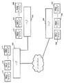
[00105] 他の実施形態では、システムが多数のハブを含むことができ、各ハブが1つ以上の移動体ディスプレイ・デバイスを含む。これらのハブは、互いに直接またはインターネット(または他のネットワーク)を介して通信することができる。例えば、図7はハブ560、562、および564を示す。ハブ560は、直接ハブ562と通信する。ハブ560は、ハブ564とインターネットを介して通信する。ハブ560は、移動体ディスプレイ・デバイス570、572、...、574と通信する。ハブ562は、移動体ディスプレイ・デバイス578、580、...、582と通信する。ハブ564は、移動体ディスプレイ・デバイス584、586、...、588と通信する。先に論じたように、移動体ディスプレイ・デバイスの各々は、それらそれぞれのハブと、ワイヤレス通信を介して通信する。これらのハブが共通の環境にある場合、これらのハブの各々は環境のモデルの一部を設けることができ、または1つのハブが他のハブのためにモデルを作成することができる。これらのハブの各々は、動いている物体の一部(subset)を追跡し、その情報を他のハブと共有する。一方、他のハブは、しかるべき移動体ディスプレイ・デバイスとこの情報を共有する。移動体ディスプレイ・デバイスについてのセンサー情報が、それらそれぞれのハブに提供され、次いで他のハブに分配され、最終的に他の移動体ディスプレイ・デバイスに分配される。つまり、ハブ間で共有される情報は、骨格追跡、モデルについての情報、アプリケーションの種々の状態、およびその他の追跡を含むことができる。ハブおよびそれらそれぞれの移動体ディスプレイ・デバイス間で伝えられる情報には、動いている物体の追跡情報、世界モデルについての状態および物理的更新(physics updates)、幾何学的形状および表面模様の情報、ビデオおよびオーディオ、ならびに本明細書において記載される動作を実行するために用いられる他の情報が含まれる。
[00105] In other embodiments, the system can include multiple hubs, each hub including one or more mobile display devices. These hubs can communicate with each other directly or via the Internet (or other network). For example, FIG. 7 shows
[00106] 図8は、頭部装着ディスプレイ・デバイスのユーザーに提示する可視化情報の表示を最適化するプロセスの一実施形態を説明する。ステップ600において、システム10を構成する。例えば、アプリケーション(図5のアプリケーション452)が、場面の三次元モデルにおける指定位置に最適画像を挿入することを示すように、本システムを構成することができる。他の例では、ハブ計算システム12上で実行するアプリケーションが、ビデオ・ゲームまたは他のプロセスの一部として拡張コンテンツ(特定の仮想画像または仮想物体というような)を場面内に挿入するように指示する。
[00106] FIG. 8 illustrates one embodiment of a process for optimizing the display of visualization information to be presented to a user of a head mounted display device. In
[00107] ステップ605において、ユーザーの環境において関心のある物体を判定する。一実施形態では、これは、ステップ602から606において概要を説明するように、ユーザーの空間の三次元モデルを作成することによって行うことができる。ステップ602において、本システムは、頭部装着ディスプレイ・デバイス2を配置する空間の立体モデルを作成する。一実施形態では、例えば、ハブ計算デバイス12は、1つ以上の深度カメラからの深度画像を用いて、頭部装着ディスプレイ・デバイス2を配置する環境または場面の三次元モデルを作成する。ステップ604において、このモデルを1つ以上の物体に区分する。例えば、ハブ計算デバイス12が部屋の三次元モデルを作成する場合、この部屋はその内部に多数の物体を有することがありそうに思われる。部屋の中にある可能性がある物体の例には、人、椅子、テーブル、ソファ等が含まれる。ステップ604は、別個の物体を互いから区別することを含む。ステップ606において、本システムはこれらの物体を特定する。例えば、ハブ計算デバイス12は、1つの特定の物体がテーブルであり、他の物体が椅子であることを特定することができる。
[00107] In
[00108] あるいは、ステップ605は、多数の手段のいずれでも実行することができる。一実施形態では、部屋の中にある1つ以上の物体または個人にセンサーを埋め込むこともできる。センサーは、対象の物体を識別する検出可能な信号を発信し、または物体のタイプおよび特定のアプリケーションに対して物体に対して抱くかもしれない関心のレベルというような追加情報を提供する検出可能な信号を発信し、ユーザーの環境において物体を識別するために用いることができる。あるいは、先に開示したキャプチャー・デバイス、または他の距離検出センサー技術(SONAR、LIDAR、構造化光、および/または飛行時間距離検出器)を採用した他のセンサー・デバイスを環境内または頭部装着ディスプレイ・デバイス上に配し、その範囲内にある物体を識別するために他のセンサー技術を用いることもできる。これらは全て、可能な注目物体(focal object)およびその形状を規定するために用いることができる。 [00108] Alternatively, step 605 may be performed by any of a number of means. In one embodiment, the sensor may be embedded in one or more objects or individuals in the room. The sensor emits a detectable signal that identifies the object of interest, or provides a detectable information that provides additional information such as the type of object and the level of interest that the object may have for a particular application. Signals can be sent and used to identify objects in the user's environment. Alternatively, the previously disclosed capture devices or other sensor devices that employ other distance sensing sensor technologies (SONAR, LIDAR, structured light, and / or time-of-flight distance detectors) can be mounted in the environment or head mounted Other sensor technologies can also be used to identify objects that are placed on and within the display device. All of these can be used to define possible focal objects and their shapes.
[00109] 他の代替案は、以上で説明した深度カメラの内1つ以上を用いて、環境のステレオ再現を、一度に1フレームずつ実行することである。更に他の代替案では、物体自体が、頭部装着ディスプレイに向けられた光パルスを放出し、その物体が対象であること、そしてこの物体を含む表示の部分を強調すべきことを、ディスプレイに示すのでもよい。 [00109] Another alternative is to perform stereo reproduction of the environment one frame at a time using one or more of the depth cameras described above. In yet another alternative, the display itself indicates that the object itself emits a light pulse directed at the head mounted display, that the object is of interest, and that the portion of the display that contains this object should be emphasized. It may be shown.
[00110] 図8のステップ608において、本システムは、モデルまたは以上の技法に基づいてユーザーの視野を判定する。即ち、本システムはユーザーが見ている環境または空間の部分を判定する。一実施形態では、ステップ608は、ハブ計算デバイス12、演算装置4、および頭部装着ディスプレイ・デバイス2を用いて実行することができる。一実施態様例では、ハブ計算デバイス12がユーザーおよび頭部装着ディスプレイ・デバイス2を追跡して、頭部装着ディスプレイ・デバイス2の位置および向きについて暫定的な判定を行う。頭部装着ディスプレイ・デバイス2上にあるセンサーを用いて、判定した向きを厳密に定める。例えば、先に説明した慣性センサー34は、頭部装着ディスプレイ・デバイス2の向きを厳密に定めるために用いることができる。加えて、以下で説明する目追跡プロセスも、最初に判定した視野の内、特にユーザーが見ているところ、あるい視野においてユーザーの焦点領域または深度焦点として把握したところに対応する一部(subset)を特定するために用いることができる。これ以上の詳細については、図12、図13A、および図13Bに関して以下で説明する。
[00110] In
[00111] ステップ610において、演算装置4において実行するソフトウェアというような本システムは、ユーザーの視野内においてユーザーの現焦点領域を判定する。図13Aおよび図13Bにおいて以下で更に論ずるが、目毎に目追跡カメラ134によって取り込まれたデーターに基づく目追跡処理によって、ユーザーの現在の焦点領域を規定することができる。例えば、瞳間の収斂(convergence)は、ユーザーの顔の位置を示すデーターと共に、焦点曲線、即ち、ホロプター上の焦点距離まで三角測量するために用いることができる。焦点領域、即ち、パナムの融合エリアは、この焦点から計算することができる。パナムの融合エリアとは、人間の目によって用いられる両眼立体視に対する単一視のエリアである。
[00111] In
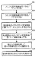
[00112] ステップ612において、演算装置4は、単独でまたはハブ計算デバイス12と協同して(ソフトウェアの制御下で)、ユーザーの焦点領域内において1つ以上の物体と相互作用するユーザーの意図を判定する。ステップ614において、ソフトウェアの制御の下で、演算装置4は、単独でまたはハブ計算デバイス12と協同して、1つ以上の物体と相互作用するユーザーの意図に基づいて最適画像を生成し、この最適画像をユーザーに表示する。
[00112] In
[00113] ステップ616において、頭部装着ディスプレイ・デバイス2のユーザーは、頭部装着ディスプレイ・デバイス2上に表示された最適画像に基づいて、ハブ計算デバイス12(または他の計算デバイス)上で実行するアプリケーションと相互作用を行う。図8の処理ステップ(608〜616)は、ユーザーが彼または彼女の頭部を動かすに連れてユーザーの視野および焦点領域を更新し、ユーザーの焦点領域において1つ以上の物体と相互作用するユーザーの意図を判定し、ユーザーの意図に基づいて最適画像をユーザーに表示するように、本システムの動作中に連続して実行することができる。ステップ604〜614の各々については、以下で詳細に説明する。
[00113] In
[00114] 図9は、ユーザーの空間のモデルを作成するプロセスの一実施形態を説明する。例えば、図9のプロセスは、図8のステップ602の一実施態様例である。ステップ620において、ハブ計算デバイス12は頭部装着ディスプレイ・デバイス2が存在する空間の、図1に示したもののような、多数の視線(perspective)に対する1つ以上の深度画像を受け取る。例えば、ハブ計算デバイス12は、多数の深度カメラから深度画像を得ることができ、あるいはカメラを異なる方向に向けることによって、またはモデルを構築する空間の全視野(full view)を可能にするレンズを有する深度カメラを用いることによって、同じカメラから複数の深度画像を得ることができる。ステップ622において、種々の深度画像からの深度データーを共通座標系に基づいて組み合わせる。例えば、このシステムが深度画像を多数のカメラから受け取る場合、本システムは2つの画像を相関付けて共通の座標系を有する(例えば、画像を並べる)。ステップ624において、深度データーを用いて、空間の立体記述を作成する。
[00114] FIG. 9 illustrates one embodiment of a process for creating a model of a user's space. For example, the process of FIG. 9 is an example implementation of
[00115] 図10は、空間のモデルを物体に区分するプロセスの一実施形態を説明するフローチャートである。例えば、図10のプロセスは、図8のステップ604の一実現例である。図10のステップ626において、本システムは、先に論じたように、1つ以上の深度画像を1つ以上の深度カメラから受け取る。あるいは、本システムは、既に受け取っている1つ以上の深度画像にアクセスすることもできる。ステップ628において、本システムは、1つ以上の仮想画像を前述したカメラから受け取る。あるいは、本システムは、既に受け取られている1つ以上の仮想画像にアクセスすることもできる。ステップ630において、ハブ計算システム12は、深度画像および/または視覚画像に基づいて1人以上の人を検出する。例えば、本システムは1つ以上の骨格を認識する。ステップ632において、ハブ計算デバイス12は、深度画像および/または視覚画像に基づいてモデル内で縁端を検出する。ステップ634において、ハブ計算デバイス12は、検出した縁端を用いて、別個の物体を互いから識別する。例えば、縁端が物体間の境界であると仮定する。ステップ636において、モデルのどの部分が異なる物体と関連付けられているかを示すために、図9のプロセスを用いて作成したモデルを更新する。
[00115] FIG. 10 is a flow chart describing one embodiment of a process for partitioning a spatial model into objects. For example, the process of FIG. 10 is an implementation of
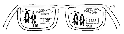
[00116] 図11Aは、物体を特定するプロセスの一実施形態を説明するフローチャートである。例えば、図11Aのプロセスは、図8のステップ606の一実施態様例である。ステップ640において、ハブ計算デバイス12は、特定した人をユーザー個人情報(identity)と照合する。例えば、ユーザー・プロファイルが、キャプチャー・デバイスによって受け取られた検出物体の画像と照合することができる視覚画像を有することができる。あるいは、ユーザーのプロファイルが、深度画像または視覚画像に基づいて照合することができる人の特徴を記述することもできる。他の実施形態では、ユーザーが本システムにログインするのでもよく、ハブ計算デバイス12がログイン・プロセスを用いて個々のユーザーを特定し、本明細書において記載する相互作用の間にわたってユーザーを追跡することができる。ステップ642において、ハブ計算デバイス12は形状のデーターベースにアクセスする。ステップ644において、ハブ計算デバイスは、モデル内にあるだけの物体をデーターベースにおける形状と照合する。ステップ646において、一致しない形状を強調して、ユーザーに表示する(例えば、モニター16を用いる)。ステップ648において、ハブ計算デバイス12は、強調された形状の各々(または一部(subset))を特定するユーザー入力を受け取る。例えば、ユーザーはキーボード、マウス、音声入力、または他のタイプの入力を用いて、特定されなかった形状の各々が何であるのか示すことができる。ステップ650において、ステップ648におけるユーザー入力に基づいて、形状のデーターベースを更新する。ステップ652において、ステップ602において作成しそしてステップ636において更新した環境のモデルに、更に、物体の各々についてのメタデーターを追加することによって、このモデルを更新する。メタデーターは物体を識別する。例えば、メタデーターは、特定の物体が、丸く輝くテーブル、ジョン・ドウ(John Doe)、緑色の革製ソファー等であることを示すこともできる。
[00116] FIG. 11A is a flowchart illustrating one embodiment of a process for identifying an object. For example, the process of FIG. 11A is an example implementation of
[00117] 図11Bは、動く物体(例えば、動く人または他のタイプの物体)に応答して、図8のプロセスによって作成したモデルを更新するプロセスの一実施形態を説明するフロー・チャートである。ステップ654において、本システムは、物体が動いていることを判定する。例えば、本システムは、連続的に深度画像を受け取る。深度画像がときの経過と共に変化した場合、物体が動いていることになる。動いている物体が検出されない場合、本システムは深度画像を受け続け、動いている物体を探し続ける。
[00117] FIG. 11B is a flow chart illustrating one embodiment of a process for updating a model created by the process of FIG. 8 in response to a moving object (eg, a moving person or other type of object). . In
[00118] 動いている物体がある場合、ステップ654において、本システムはその動いている物体を特定する。動いている物体を認識し、認識した物体を図8のステップ606において特定した物体の内1つと相関付けるために、フレーム差分抽出(differencing)または種々の追跡技術の内いずれかを用いることができる。物体の中には、動いているときに形状を変化させるものもある。例えば、人間が歩くまたは走ると、人間は体形が変化する場合がある。ステップ658において、動く物体の新たな位置および形状に基づいて、以前に作られた環境のモデルを更新する。ステップ660において、動く物体の新たな形状を特定し、格納する。図11Bのプロセスは、ハブ計算デバイス12の演算装置4によって実行することができる。
[00118] If there is a moving object, in
[00119] 図12は、図8のステップ608の一実施態様例である、ユーザーの視野を判定するプロセス、更に図8のステップ610の一実施態様例である、ユーザーの焦点領域を判定するプロセスの一実施形態を説明するフローチャートである。図12のプロセスは、ハブ計算デバイス12からの情報および先に説明した目追跡技術を拠り所とする。図13Aは、図12のプロセスにおいて用いられる追跡情報を提供するためにハブ計算システムによって実行するプロセスの一実施形態を説明するフローチャートである。図13Bは、目を追跡するプロセスの一実施形態を説明するフローチャートであり、この結果は図12のプロセスによって用いられる。
[00119] FIG. 12 is a process for determining a user's field of view, which is an example embodiment of
[00120] 図13Aのステップ686において、ハブ計算デバイス12は、ユーザーの位置を追跡する。例えば、ハブ計算デバイス12は、1つ以上の深度画像および1つ以上の視覚画像を用いてユーザーを追跡する(例えば、骨格追跡を用いる)。1つ以上の深度画像および1つ以上の視覚画像は、ステップ688において頭部装着ディスプレイ・デバイス2の位置、および頭部装着ディスプレイ・デバイス2の向きを判定するために用いることができる。ステップ690において、ユーザーおよび頭部装着ディスプレイ・デバイス2の位置ならびに向きを、ハブ計算デバイス12から演算装置4に送信する。ステップ692において、演算装置4においてこの位置および配向情報を受け取る。図13Aの処理ステップは、ユーザーを連続的に追跡するように、本システムの動作中継続して実行することができる。
[00120] In
[00121] 図13Bは、環境においてユーザーの目の位置を追跡する一実施形態を説明するフローチャートである。ステップ662において、目に照明を当てる。例えば、目追跡照明134Aからの赤外線光を用いて、目に照明を当てることができる。ステップ664において、1つ以上の目追跡カメラ134Bを用いて目からの反射を検出する。ステップ665において、頭部装着ディスプレイ・デバイス2から演算装置4に反射データーを送る。ステップ668において、演算装置4は、先に論じたように、反射データーに基づいて目の位置を判定する。
[00121] FIG. 13B is a flowchart describing one embodiment of tracking the position of a user's eyes in an environment. In
[00122] 図12は、ユーザーの視野を判定するプロセス(例えば、図8のステップ608)およびユーザーの焦点領域を判定するプロセス(例えば、図8のステップ610)の一実施形態を説明するフローチャートである。ステップ670において、演算装置4は、ハブから受け取った最新の位置および配向情報にアクセスする。図12のプロセスは、ステップ814からステップ810への矢印によって示されるように、連続的に実行することができ、したがって、演算装置4は周期的に更新された位置および配向情報を、ハブ計算デバイス12から受け取る。しかしながら、演算装置4は、ハブ計算デバイス12から更新情報を受け取るよりも高い頻度で仮想画像を描画する必要がある。したがって、演算装置4は、ローカルに(例えば、頭部装着ディスプレイ・デバイス2から)検知された情報を拠り所として、ハブ計算デバイス12からのサンプルの間に、向きに対する更新を行う必要がある。
[00122] FIG. 12 is a flowchart describing one embodiment of a process for determining a user's field of view (eg,
[00123] ステップ672において、演算装置4は、三軸ジャイロ132Bからのデーターにアクセスする。ステップ674において、演算装置4は三軸加速度132Cからのデーターにアクセスする。ステップ676において、演算装置4は三軸磁力計132Aからのデーターにアクセスする。ステップ678において、演算装置4は、ジャイロ、加速度計、および磁力計からのデーターによって、ハブ計算デバイス12からの位置および配向データーを厳密に定める(または、言い換えると、更新する)。ステップ680において、演算装置4は、頭部装着ディスプレイ・デバイスの位置および向きに基づいて、潜在的な視点(point of view)を判定する。
[00123] In
[00124] ステップ682において、演算装置4は最新の目位置情報にアクセスする。ステップ684において、演算装置4は、ユーザーによって見られているモデルの部分を、潜在的な視野の一部として目の位置に基づいて判定する。例えば、ユーザーが壁に向かっていることもあり、したがって、頭部装着ディスプレイの視点は、壁に沿ったいずれかの場所を含むこともあり得る。しかしながら、ユーザーの目が右に向けられている場合、ステップ684では、ユーザーの視野は壁の右側部分のみであると結論付ける。ステップ684の終了時には、演算装置4は頭部装着ディスプレイ2を介したユーザーの視点を判定し終えている。次いで、演算装置4は、その視野内において、不透明フィルターを用いて仮想画像を挿入し光を遮断する位置を特定することができる。図12の処理ステップは、ユーザーが彼または彼女の頭部を動かすに連れてユーザーの視野および焦点領域が連続的に更新されるように、本システムの動作中に連続的に実行することができる。
[00124] In
[00125] 図14は、ユーザーの焦点領域において1つ以上の物体と相互作用するユーザーの意図を推論して判定するか、または意図が表現されたことを判定するプロセスの一実施形態を説明するフローチャートである。例えば、図14のプロセスは、図8のステップ612の一実施態様例である。図14のステップは、ソフトウェアの制御の下で、ハブ計算デバイス12または演算装置4によって実行することができる。図14は、ユーザーの焦点領域内において1つ以上の物体と相互作用するユーザーの意図を、ユーザーの焦点領域におけるユーザーの目の移動パターンの検出に基づいて判定し、更にユーザーの焦点領域においてユーザーが見ている1つ以上の物体上におけるユーザーの凝視の強さを判定するプロセスについて説明する。図14Aは、ユーザーに関するユーザー特定情報に基づいて、1つ以上の物体または人と相互作用するユーザーの意図を推論するプロセスを説明する。図14Bは、ユーザーが表現した1つ以上の物体と相互作用する意図に基づいて、1つ以上の物体と相互作用する意図を判定するプロセスを説明する。
[00125] FIG. 14 illustrates one embodiment of a process for inferring and determining a user's intention to interact with one or more objects in the user's focal region or determining that the intention has been expressed. It is a flowchart. For example, the process of FIG. 14 is an example implementation of
[00126] 図14のステップ690において、ユーザーの焦点領域におけるユーザーの目の移動パターンを検出する。認められるように、目の動きは、通例、目の凝視がある位置において停止しているとき、および他の位置に動くときに、固視(fixation)および断続性運動(saccades)にそれぞれ分割される。したがって、目移動パターンは、画像または視覚的場面を見ているときに、ユーザーの目が続けて行う(follow)一連の固視および断続性運動として定義することができる。結果的に得られる一連の固視および断続性運動は、一般に、スキャンパス(scanpath)と呼ばれる。これは、視覚的場面を見ているときにユーザーの目が辿る経路である。加えて、目からの情報の殆どは、固視の間に入手可能になる。視角(眼窩)の中央の1度または2度は、大量の視覚的情報を提供し、それよりも大きな離心(周辺)からの入力の方が情報が少ない。つまり、スキャンパスに沿った固視の位置は、視覚的場面を見ているときにユーザーの目によって処理される刺激に関する情報位置(information loci)を示す。一例では、スキャンパスに沿った固視の位置は、ユーザーの焦点領域においてユーザーが見ている1つ以上の物体を検出するために用いることができる。
[00126] In
[00127] ステップ692において、ユーザーがユーザーの焦点領域において1つ以上の物体を見ているか否か判定を行う。先に論じたように、一例では、スキャンパスに沿った固視の位置は、ユーザーがユーザーの焦点領域において1つ以上の物体を見ているか否か検出するために用いることができる。ユーザーが何の物体も見ていないと判定した場合、一実施形態では、図14Aにおいて説明するステップ(710〜716)を実行する。
[00127] At
[00128] ユーザーがユーザーの焦点領域において1つ以上の物体を見ていると判定した場合、ステップ694において、ユーザーが見ている物体を特定する。図11において説明したプロセスを利用することによって、1つ以上の物体を特定することができる。例えば、物体は、壁掛け時計、丸く輝くテーブル、ジョン・ドウ、緑色の革製ソファー等として特定することができる。ステップ696において、ユーザーの焦点領域においてユーザーが見ている1つ以上の物体上におけるユーザーの凝視の強さを判定する。一例では、ユーザーの凝視の強さは、ある時間枠以内における物体上のユーザーの凝視(または固視)の期間を判定することに基づいて判定する。
[00128] If the user determines that he or she is looking at one or more objects in the user's focus area, then in
[00129] ステップ698において、ユーザーの凝視の強さが既定の閾値よりも大きいか否か判定を行う。一例では、既定の閾値は10秒である。凝視の強さが既定の閾値よりも大きい場合、ステップ700において、ユーザーの焦点領域において1つ以上の物体と相互作用するユーザーの意図を推論する。一例では、ユーザーの環境の中にある物体の各々が、物体と相互作用するユーザーの位置を表すパラメータを含むことができる。一例では、システム10は、物体と相互作用するユーザーの意図を判定するとき、二進値を物体のパラメータに割り当てることができる。二進値が1のとき、物体と相互作用するユーザーの意図を表す。ステップ700において、ユーザーの意図をユーザー・プロファイル・データーベース470に格納する。
[00129] In
[00130] 他の例では、ユーザーの凝視の強さ(ステップ696において判定した)は、物体を見ながらユーザーが行っている活動の形式も判定することができる。例えば、ユーザーの凝視の強さから導かれた断続性運動のシーケンスの長さを用いて、ユーザーが物体を調べているのか/漫然と見ているのか、物体によって表示される文章を読んでいるのか、物体について考えているのか、または物体を真剣に見ているのか判定することができる。一実施形態では、ユーザーが行っている活動の形式を、物体上におけるユーザーの凝視の強さによって判定し、更に物体と相互作用するユーザーの意図を推論するために用いることもできる。 [00130] In another example, the strength of the user's gaze (determined in step 696) can also determine the type of activity the user is performing while looking at the object. For example, whether the user is looking at the object / looking loosely, or reading the text displayed by the object, using the length of the intermittent motion sequence derived from the user's gaze intensity , Whether you are thinking about the object or you are seriously looking at the object. In one embodiment, the type of activity a user is performing may be determined by the strength of the user's gaze on the object and may be used to infer the user's intention to interact with the object.
[00131] ステップ698において、ユーザーの凝視の強さが既定の閾値より大きくないと判定した場合、一実施形態では、図14Bにおいて説明するプロセスのステップ(720〜724)を実行する。
[00131] If it is determined in
[00132] 図14Aは、ユーザーの焦点領域において1つ以上の物体と相互作用するユーザーの意図を判定するプロセスの他の実施形態を説明するフローチャートである。一実施形態では、図14Aにおいて説明するプロセスを実行するのは、ユーザーがユーザーの焦点領域においていずれの特定の物体も見ていないことを、ユーザーの目の移動パターンが示すとき(例えば、図14のステップ692)である。例えば、HMDデバイスを着用しているユーザーの視力が正常でなく、彼または彼女の環境において物体または人々を非常に明確に見ることができないかもしれないという状況例について考える。1つの手法では、1つ以上の物体または人と相互作用するユーザーの意図は、ユーザーに関するユーザー特定情報にアクセスすることによって、自動的に推論することができる。ユーザーの意図を自動的に判定するプロセスについては、ステップ710〜716において以下で説明する。 [00132] FIG. 14A is a flowchart describing another embodiment of a process for determining a user's intention to interact with one or more objects in the user's focal region. In one embodiment, the process described in FIG. 14A is performed when the movement pattern of the user's eyes indicates that the user is not looking at any particular object in the user's focus area (eg, FIG. 14). Step 692). For example, consider an example situation where a user wearing an HMD device has abnormal vision and may not be able to see objects or people very clearly in his or her environment. In one approach, a user's intention to interact with one or more objects or people can be inferred automatically by accessing user-specific information about the user. The process of automatically determining user intent is described below in steps 710-716.
[00133] ステップ710において、ユーザーに関するユーザー特定情報に、ユーザー・プロファイル・データーベース470からアクセスする。先に論じたように、ユーザー特定情報は、ユーザーが表現した好み、ユーザーの友人のリスト、ユーザーが好む活動、ユーザーの備忘録のリスト、ユーザーのソーシャル・グループ、ユーザーの現在地、ユーザーの環境、ならびにユーザーの写真、画像、および記録ビデオというような、その他のユーザー作成コンテンツといった、ユーザーに関する情報を含むことができる。
[00133] In
[00134] ステップ712において、ユーザーの焦点領域における物体または人のいずれかが、ユーザー特定情報と相関があるか否か判定を行う。例えば、ユーザーがパーティにおいて彼または彼女の友人を見つけようとしていうという状況例では、ユーザーの焦点領域内に現れる人を、ユーザーに関するユーザー特定情報と相関付けて、これらの人々の1人以上がユーザーの友人のいずれかに対応するか否か判定を行うことができる。例えば、ユーザーの焦点領域内にいる人々の画像を、ユーザー・プロファイル・データーベース470に格納されているユーザーの友人の視角画像と相関付けて、ユーザーの焦点領域内にいる人々の内ひとり以上が、ユーザーの友人のいずれかに対応するか否か判定を行うために、顔認識技法を利用することもできる。
[00134] In
[00135] ステップ712において、ユーザーの視野における物体や人々のいずれもユーザー特定情報と相関がないと判定した場合、本プロセスは、図8におけるステップ608におけるユーザーの視野追跡に戻る。一例では、ユーザーの視野における物体や人々のいずれもユーザー特定情報と相関がないと判定した場合、「現在貴方の焦点領域には対象の物体や人はいません」というような仮想テキスト・メッセージを、ユーザーのHMDを介して、ユーザーに表示することができる。
[00135] If in
[00136] ステップ714において、相関に基づいて、1つ以上の物体または人を特定する。例えば、ユーザーの友人、ジョン・ドウ、およびサリー・ドウ(Sally Doe)として、人を識別することができる。他の実施形態では、ユーザーのキー(key)が、場面内に置かれたものとして識別することができる。ステップ716において、特定された物体または人と相互作用するユーザーの意図を、相関に基づいて自動的に推論する。先に論じたように、一例では、本システムは、物体または人と相互作用するユーザーの意図を判定したときに、1つ以上の識別した物体または人によって表されるパラメーターに二進値を割り当てる。ステップ716において、ユーザー・プロファイル・データーベース470に、1つ以上の識別した物体と相互作用するユーザーの意図を格納する。ステップ716は、ユーザー特定の要因または外部の要因に基づいて、自動的に意図を推論することを含んでもよい。このような要因には、限定ではなく、ユーザーのカレンダーまたはスケジュール情報、連絡先データーベースまたはソーシャル・グラフ(social graph)に格納されているユーザーの友人情報、地理的測位情報、時刻等を含むことができる。例えば、ユーザー特定情報が、月曜日にユーザーが会議に出席する予定になっていることを示し、ユーザーのラップトップが視野内にある。図15Cにおいて以下で示す説明にしたがって、本システムは、ラップトップを強調して、そのラップトップを会議に持って行くことを忘れないように、ユーザーに説き勧めることができる。
[00136] At
[00137] 図14Bは、1つ以上の物体と相互作用することを表現したユーザーの意図に基づいて、1つ以上の物体と相互作用するユーザーの意図を判定するプロセスの他の実施形態を説明するフローチャートである。一実施形態では、図14Bにおいて説明するプロセスを実行するのは、例えば、ユーザーがユーザーの焦点領域内で1つ以上の物体を見ているが、ユーザーの凝視の強さは十分に長くないときである(即ち、図14のステップ698において論じたように、既定の閾値よりも大きくない)。ステップ720において、ユーザーの焦点領域において1つ以上の物体と相互作用する意図を指定または表現するように、ユーザーに促す。一例では、本システムは、ユーザーのHMDデバイスを介してユーザーに仮想テキストを表示して、1つ以上の物体と相互作用する意図を指定するようにユーザーに促すことができる。例えば、音声入力、キーボード入力、接触、またはジェスチャーというような、ユーザーの身体的行為によって意図を指定するように、ユーザーに促すことができる。音声入力は、発話した単語、口笛、叫び、およびその他の発声というような、ユーザーが発声する音声コマンドとすることができる。例えば、ユーザーがパーティにおいて彼または彼女の友人を見つけようとする状況例では、ユーザーは、「私の友人を見つけるのを手伝って下さい」というようなコマンドを発声することができる。
[00137] FIG. 14B illustrates another embodiment of a process for determining a user's intention to interact with one or more objects based on the user's intention expressing interacting with one or more objects. It is a flowchart to do. In one embodiment, the process described in FIG. 14B is performed when, for example, the user is looking at one or more objects in the user's focus area, but the user's gaze intensity is not long enough. (Ie, not greater than a predetermined threshold as discussed in
[00138] 手を叩くというような音声以外の音響も、ユーザーから受け取ることができる。一例では、音声入力または音声以外の音響は、図3に示した頭部装着ディスプレイにおけるマイクロフォン110、または図5に示したキャプチャー・デバイス423におけるマイクロフォン430によって取り込むことができる。ユーザーからのジェスチャーは、微笑み、笑い顔、または激励というような、ユーザーが行う顔の表情を含むことができる。一例では、ジェスチャーは、ハブ計算デバイス12における認識エンジン454によって取り込むことができる。
[00138] Sounds other than sound such as clapping can be received from the user. In one example, voice input or sound other than voice can be captured by the
[00139] ステップ722において、1つ以上の物体と相互作用する意図がユーザーによって受け取られたか否か判定を行う。ユーザーの意図が未だ受け取られていない場合、ステップ704において、本プロセスは図8におけるステップ608のユーザーの視野追跡に戻る。ユーザーの意図が受け取られている場合(身体的行為によって)、1つ以上の物体と相互作用するユーザーの意図を判定し、ユーザーが指定した意図または表現した意図を、ユーザー・プロファイル・データーベース470に格納する。
[00139] In
[00140] 図15Aは、1つ以上の物体と相互作用するユーザーの意図を推論して判定するか、または意図が表現されたことを判定することに基づいて最適画像を生成し、この最適画像をユーザーに表示するプロセスの一実施形態を説明するフローチャートである。一実施形態では、最適画像を生成するには、ユーザーの焦点領域においてユーザーが相互作用しようとする物体の外観を視覚的に強調すること、およびユーザーの焦点領域の外側であるがユーザーの視野内にあり、ユーザーが相互作用しようとしない物体の外観を目立たなくすることを含む。例えば、図15Aのプロセスは、図8のステップ614の一実施態様例である。図15Aのステップは、ソフトウェアの制御の下で、ハブ計算デバイス12または演算装置4によって実行することができる。
[00140] FIG. 15A generates an optimal image based on inferring or determining a user's intention to interact with one or more objects, or determining that the intention has been expressed, 6 is a flowchart illustrating one embodiment of a process for displaying a message to a user. In one embodiment, an optimal image is generated by visually enhancing the appearance of an object that the user wants to interact with in the user's focal region, and outside the user's focal region but within the user's field of view. And obscure the appearance of objects that the user does not attempt to interact with. For example, the process of FIG. 15A is an example implementation of
[00141] ステップ730において、ユーザーの焦点領域の外側であるがユーザーの視野内に入る物体の外観を目立たなくする。一実施形態では、HMDデバイス2における不透明フィルター114を利用して、ユーザーの焦点領域の外側にある物体を遮るか暗くして、ユーザーの焦点領域の外側にある物体の外観を目立たなくする。つまり、実世界場面の内、ユーザーに関心がない部分は、不透明フィルター114によってユーザーの目に届かないように遮ることができ、ユーザーの焦点領域においてユーザーが相互作用しようとする物体が、ユーザーにとって明白に見えるようにする。
[00141] In
[00142] ステップ732において、ユーザーの焦点領域においてユーザーが相互作用しようとする物体を視覚的に強調する。一実施形態では、HMDデバイス2におけるマイクロ・ディスプレイ・アセンブリー120を利用して、ユーザーの焦点領域内にある物体を視覚的に強調する。1つの手法では、物体の縁端を際立たせることによって視覚的に強調する。他の手法では、物体が配置されている領域内において仮想的なボックス、円、または仮想的なインディケーターを表示することによって、物体を視覚的に強調する。加えて、物体を視覚的に強調するには、カラーも用いることができる。
[00142] At
[00143] ステップ734において、1つ以上の物体に関係がある拡張コンテンツを読み出す。一例では、拡張コンテンツは、ユーザー・プロファイル・データーベース470から読み出したユーザー特定情報を含むことができる。他の例では、拡張コンテンツは、ユーザーのソーシャル・ネットワーキング・サイト、住所録、電子メール・データー、インスタント・メッセージング・データー、ユーザー・プロファイル、またはインターネット上にあるその他のソースからリアル・タイムで読み出されたユーザー特定情報を含むこともできる。
[00143] In
[00144] ステップ736において、特定した物体に関係があるオーディオ・コンテンツを抽出する。ステップ736は任意選択肢である。例えば、ユーザーがユーザーの居間において壁掛け時計を見ており、ユーザーが壁掛け時計オブジェクトと相互作用しようとしていると判定した場合、時刻についてのオーディオ情報をユーザーが聴くことができる。また、例えば、ユーザーが彼または彼女の友人と共にパーティにおり、ユーザーがそのパーティにおいて特定の友人のグループと交流しようとしていると判定した場合、ユーザーはその特定のユーザーのグループからの声のみを聴くことができる。
[00144] In
[00145] ステップ738において、ユーザーの焦点領域における1つ以上の物体に被せて、またはその隣りに、拡張コンテンツを投射する。一例では、拡張コンテンツは、ユーザーに表示される1つ以上の仮想物体または仮想テキストを含む仮想画像である。他の例では、拡張コンテンツは、1つ以上の選択肢があるメニューというような、仮想物体を含むこともできる。
[00145] In
[00146] ステップ740において、頭部装着ディスプレイ・デバイス2を介してユーザーに最適画像を表示する。最適画像は、ユーザーの焦点領域において強調した外観の物体、およびユーザーの焦点領域の外側で外観を目立たなくした物体を含み、任意に、1つ以上の物体に関係する拡張コンテンツも含むことができる。最適画像を生成しこの最適画像をユーザーに表示する様子の図示例を、図16A〜図16C、図17A〜図17D、および図18A〜図18Cに示す。
[00146] In
[00147] 一例では、演算装置4が、拡張コンテンツをマイクロ・ディスプレイ120上に表示する命令を、制御回路136のディスプレイ・ドライバー220に送る。次いで、レンズ・システム122が、マイクロ・ディスプレイ120から受け取った仮想画像を、反射面124上に、そしてユーザーの目に向けて、または導光光学エレメント112内に、ユーザーが見るために投射する。一実施態様では、ユーザーが頭部装着ディスプレイ・デバイスにおいて透視しているディスプレイ(例えば、導光光学エレメント112)を、画素に分割する。最適画像は、これらの画素によってターゲット位置において表示される。加えて、非現実的な視覚効果を防止するために不透明フィルター114を用いてもよい。例えば、不透明フィルター114は、前景仮想物体を通して背景仮想物体が見られないように、導光光学エレメント112内の画素への光を変更することができる。
[00147] In one example, the
[00148] 図15Bは、最適画像内に表示された拡張コンテンツと相互作用するユーザーの意図を推論して判定するか、または意図が表現されたことを判定することに基づいて、追加の拡張コンテンツを表示するプロセスの一実施形態を説明するフローチャートである。一例では、図15Aのステップ740において説明したように最適画像を表示するときに、ユーザーに追加の拡張情報を提示することができる。例えば、ユーザーがユーザーの居間にあるテーブルの上に置かれたりんごの籠を見ており、ユーザーがこのりんごの籠と相互作用しようとしていると判定したという状況を考える。りんごの籠の外観を視覚的に強調した最適画像を、ユーザーに表示する。また、最適画像は、選択肢のメニューというような仮想物体を含む拡張コンテンツもユーザーに投射することを仮定する。
[00148] FIG. 15B illustrates additional augmented content based on inferring or determining a user's intention to interact with the expanded content displayed in the optimal image or determining that the intention has been expressed. FIG. 6 is a flowchart illustrating an embodiment of a process for displaying. In one example, additional extended information can be presented to the user when displaying the optimal image as described in
[00149] ステップ756において、メニューによって表示された選選択肢と相互作用するユーザーの意図を判定する。ユーザーの意図は、図14において説明したプロセスによって論じたように、判定するとよい。ステップ760において、ユーザーの意図に基づいて、メニューにおける選択肢のユーザー選択を受け取る。ステップ762において、拡張コンテンツを読み出し、更に任意にメニューの選択肢に関係するオーディオ情報を読み出す。ステップ762において、最適画像において視覚的に強調した物体に被せて、またはその隣に拡張コンテンツを投射する。選択肢のメニューを含む最適画像を表示し、メニューの選択肢と相互作用するユーザーの意図を判定する様子の図示例を、図17A〜図17Dに示す。
[00149] In
[00150] ここで開示する技術の他の実施形態では、ユーザーの環境における可視情報のユーザーの理解は、ユーザーの環境における所要の物体を自動的に強調することによって、高められる。図15Cは、ユーザーの環境において可視情報のユーザーの理解を高めるプロセスを説明する。ステップ770において、ユーザーの焦点領域において、ユーザーの環境のユーザーの理解を高める1つ以上の物体を特定する。一例では、ユーザーの理解を高める物体は、ユーザーの環境についての情報をリアル・タイムで収集することによって、特定することができる。例えば、この情報には、ユーザーの環境における緊急事態の合図、あるいはユーザーの環境における有害物質の存在または鋭い物体の存在を含むことができる。他の例では、ユーザーの理解を高める物体は、図14Bに関して先に注記したように、ユーザーに関係があるユーザー特定情報に基づいて特定することもできる。例えば、ユーザーに関係があるユーザー特定情報は、ユーザーの居間においてりんごの籠のような物体が特定されたときに、ユーザーがおやつを食べるときであることを指定する備忘録を含むことができる。
[00150] In other embodiments of the disclosed technology, the user's understanding of visible information in the user's environment is enhanced by automatically highlighting the required objects in the user's environment. FIG. 15C illustrates a process for enhancing the user's understanding of visible information in the user's environment. In
[00151] ステップ772において、ユーザーの理解を高める1つ以上の物体を含む最適画像を生成する。一実施形態では、最適画像は、ユーザーの環境においてユーザーの理解を高める1つ以上の物体の外観を視覚的に強調する。1つの手法では、物体の縁端を際立たせ、物体が配置されている領域において仮想的なボックス、円、または仮想インディケーターを表示することによって、視覚的に強調する。
[00151] In
[00152] ステップ774において、最適画像において1つ以上の視覚的に強調した物体と相互作用するユーザーの意図を判定する。一例では、視覚的に強調した物体の内1つ以上と相互作用するユーザーの意図を推論することによって(図14または図14Aにおいて論じたように)、ユーザーの意図を判定することができる。他の例では、視覚的に強調した物体の内1つ以上と相互作用する意図をユーザーが表現したことに基づいて、ユーザーの意図を判定することもできる。 [00152] At step 774, the user's intention to interact with one or more visually enhanced objects in the optimal image is determined. In one example, the user's intention can be determined by inferring the user's intention to interact with one or more of the visually emphasized objects (as discussed in FIG. 14 or FIG. 14A). In another example, the user's intention may be determined based on the user's representation of the intention to interact with one or more of the visually emphasized objects.
[00153] 図16A〜図16Cは、ユーザーの環境における1つ以上の物体とのユーザーの相互作用、およびこのユーザーの相互作用に基づいた最適画像の生成の一実施形態を示す。図16Aは、ユーザーがHMDデバイス2を用いて部屋1100において1つ以上の物体を見る環境を示す。部屋1100は、前壁1102、側面壁1104、および床1108を含み、照明1106、椅子1107、壁掛け時計1118、およびテーブル1120というような家具の例も含む。ビデオ表示画面1110が、この例では、壁1102に取り付けられており、ハブ1116がテーブル1120上に載っている。状況の一例では、ユーザー1112は、HMDデバイス2を介して、前壁1102上に置かれている壁掛け時計1118のような物体を見る。1121は、ユーザーの視野を表し、1122は、ユーザーの焦点領域を表す。
[00153] FIGS. 16A-16C illustrate one embodiment of user interaction with one or more objects in the user's environment and generation of an optimal image based on the user interaction. FIG. 16A illustrates an environment in which a user views one or more objects in a
[00154] 図16Bは、壁掛け時計オブジェクト1118と相互作用するユーザーの意図を判定したときに、図16AのHMDデバイスのカメラが生成する最適画像を示す。一実施形態では、ユーザーの意図は、図14において説明したプロセスによって論じられたように、判定することができる。図16Bに示すように、最適画像1124は、ユーザーの焦点領域内における壁掛け時計オブジェクト1118の強調した外観と、ユーザーの焦点領域の外側であるがユーザーの視野内にある照明1106、表示画面1110、ハブ1116、およびテーブル1120の目立たない外観とを含む。この図示例では、壁掛け時計オブジェクト1118が、その外観を強調するために、際立たされている。物体1106、1110、1116、および1120を囲む点線は、それらの目立たない外観を示す。加えて、最適画像は壁掛け時計オブジェクト1118の隣に、時刻をディジタル・フォーマットで示す拡張コンテンツ1126を表示する。一例では、この時刻についてのオーディオ情報も、ユーザーは聴くことができる。
[00154] FIG. 16B shows the optimal image generated by the camera of the HMD device of FIG. 16A when determining the user's intention to interact with the
[00155] 図16Cは、HMDデバイスを介してユーザーが見る、図16Bの最適画像を示す。この最適画像は、HMDデバイス2のレンズ116および118の各々によって、それぞれ、供給される。開放領域1127および1128は、表示画面からの光がユーザーの目に入る位置を示す。
[00155] FIG. 16C shows the optimal image of FIG. 16B as viewed by the user through the HMD device. This optimal image is supplied by each of the
[00156] 図17A〜図17Dは、ユーザーの環境における1つ以上の物体とのユーザーの相互作用、およびユーザーの相互作用に基づく最適画像の生成の他の実施形態を示す。図17Aは、ユーザー1112がHMDデバイス2を用いて、部屋1100における1つ以上の物体を見ている環境(図16Aに示すような)を示す。図17Aの図示では、ユーザー1112は、テーブル1130上に置かれているりんごの籠1132を見ている。1121は、ユーザーの視野を表し、1122は、ユーザーの焦点領域を表す。
[00156] FIGS. 17A-17D illustrate another embodiment of user interaction with one or more objects in the user's environment and generation of an optimal image based on the user interaction. FIG. 17A shows an environment (as shown in FIG. 16A) in which the
[00157] 図17Bは、りんごの籠1132と相互作用するユーザーの意図を判定したときに、図17AのHMDデバイスのカメラによって生成する最適画像を示す。一実施形態では、図14において説明したプロセスによって、ユーザーの意図を判定することができる。最適画像1133は、ユーザーの焦点領域内におけるりんごの籠1132の強調した外観と、ユーザーの焦点領域の外側であるがユーザーの視野内にあるテーブル1120の目立たなくした外観とを含む。他の実施形態では、りんごの籠がユーザーの環境のユーザーの理解を高めると判定することに基づいて、りんごの籠の外観を自動的に強調することもできる。ユーザーの焦点領域におけるりんごの籠1132の強調した外観を含む最適画像は、図15Cにおいて説明したプロセスにしたがって生成することができる。また、最適画像1133は、拡張コンテンツ1134も表示することができる。図示する例では、拡張コンテンツ1134は、選択肢があるメニューであり、「アップル・パイを作りたいですか」または「貴方の防備録を見たいですか」をユーザー1112に表示する。
[00157] FIG. 17B shows an optimal image generated by the camera of the HMD device of FIG. 17A when determining the user's intention to interact with
[00158] 図17Cは、メニューに表示された選択肢の内1つと相互作用するユーザーの意図を判定したときにユーザーに表示する他の最適画像を示す。一実施形態では、ユーザーの意図は、図14において説明したプロセスによって判定することができる。図示する例では、最適画像1133は、ユーザーがメニューの選択肢「アップル・パイを作りたいですか」と相互作用しようとしていると判定したときに、アップル・パイを作るための材料を含む拡張コンテンツを含む。
[00158] FIG. 17C illustrates another optimal image displayed to the user when determining the user's intention to interact with one of the options displayed on the menu. In one embodiment, the user intent can be determined by the process described in FIG. In the illustrated example, the
[00159] 図17Dは、メニューにおいて表示された選択肢の内1つと相互作用するユーザーの意図を判定したときに、ユーザーに表示する最適画像を示す。図示する例では、最適画像1133は、ユーザーがメニュー選択肢「貴方の防備録を見たいですか」と相互作用しようとしていると判定したときに、ユーザーが彼または彼女のおやつを食べる時間であるというユーザーに対する備忘録を含む。
[00159] FIG. 17D shows the optimal image displayed to the user when determining the user's intention to interact with one of the options displayed in the menu. In the example shown, the
[00160] 図18A〜図18Cは、ユーザーの環境における1つ以上の物体とのユーザーの相互作用、およびユーザーの相互作用に基づく最適画像の生成の他の実施形態を示す。図18Aは、ユーザーの近所で行われた懇親会においてユーザー1112が多数の人々と会っている環境を示す。図18Aに示す状況例では、ユーザー1112は、正常な視力を有しておらず、HMDデバイス2を介して懇親会における全ての人々を明確に見ることができない可能性がある。または、ユーザーは、彼らの名前を思い出せないために、懇親会において人々とじかに交流することを望んでいないということもあり得る。
[00160] FIGS. 18A-18C illustrate another embodiment of user interaction with one or more objects in the user's environment and generation of an optimal image based on the user interaction. FIG. 18A shows an environment where a
[00161] 図18Bは、懇親会におけるひとり以上の人と交流するユーザーの意図を自動的に判定することによって、ユーザーに表示する最適画像を示す。1つの手法では、そして図14Aにおいて論じたように、ユーザーの焦点領域においてひとり以上の人と交流するユーザーの意図は、ユーザーに関係があるユーザー特定情報にアクセスすることによって、自動的に推論することができる。他の手法では、そして図14Bにおいて論じたように、ユーザーの焦点領域においてひとり以上の人と交流するユーザーの意図は、「私の友人を見つけるのを手伝って下さい」というような音声コマンドをユーザーから受け取ることによって判定することができる。最適画像1136は、ユーザーの親友である、ジョン・ドウ1136およびサリー・ドウ1138の強調された外観、ならびにユーザーの焦点領域の外側にいるがユーザーの視野内にいる、パーティにおける他の人々1138の目立たなくした外観とを含む。また、最適画像1133は、それぞれ「ここにジョン・ドウがいる」および「ここにサリー・ドウがいる」というような仮想テキスト・メッセージによって、ユーザーの友人である、ジョン・ドウ1136およびサリー・ドウ1138を特定する拡張コンテンツも表示する。ユーザーが交流しようとするかもしれない個人の判定は、ユーザーのソーシャル・グラフ(ユーザー特定情報に格納されている)の分析によって、または同時にユーザーを捜している可能性があるユーザーの友人を参照することによって(どのように判定したかは関係ない)、行うことができる。
[00161] FIG. 18B shows an optimal image displayed to the user by automatically determining the user's intention to interact with one or more people at the social gathering. In one approach, and as discussed in FIG. 14A, the user's intention to interact with one or more people in the user's focus area is automatically inferred by accessing user-specific information relevant to the user. be able to. In another approach, and as discussed in FIG. 14B, the intention of the user to interact with one or more people in the user's focus area is to prompt the user with a voice command such as “Help me find my friend”. Can be determined by receiving from. The
[00162] 図18Cは、HMDデバイスを介してユーザーが見る、図18Bの最適画像を示す。この最適画像は、HMDデバイス2のレンズ116および118の各々によって、それぞれ、供給される。開放領域1127および1128は、ビデオ表示画面からの光がユーザーの目に入る位置を示す。
[00162] FIG. 18C shows the optimal image of FIG. 18B as viewed by the user through the HMD device. This optimal image is supplied by each of the
[00163] 以上、構造的特徴および/または方法論的動作に特定な文言で主題について説明したが、添付した特許請求の範囲に定められている主題は、以上で説明した特定の特徴や動作には必ずしも限定されないことは理解されてしかるべきである。逆に、以上で説明した特定の特徴および動作は、特許請求の範囲を実現する形態例として開示されたまでである。本発明の範囲は、添付する特許請求の範囲によって定義されることを意図している。 [00163] While the subject matter has been described in language specific to structural features and / or methodological operations, the subject matter defined in the claims appended hereto is not limited to the specific features and operations described above. It should be understood that it is not necessarily limited. On the contrary, the specific features and operations described above have been disclosed as example forms for realizing the claims. The scope of the present invention is intended to be defined by the appended claims.
Claims (10)
ユーザーが透視ディスプレイ・デバイスを用いている場面において1つ以上の対象物体を判定するステップと、
前記場面におけるユーザーの視野を判定し、前記視野内において前記ユーザーの焦点領域を判定するステップと、
前記ユーザーの焦点領域において1つ以上の物体と相互作用する前記ユーザーの意図を判定するステップと、
前記ユーザーの意図に基づいて最適画像を生成するステップと、
前記透視ディスプレイ・デバイスを介して、前記最適画像を前記ユーザーに表示するステップと、
を備えている、方法。 A method of generating an optimal image based on a user's intention in an augmented reality system,
Determining one or more target objects in a scene where the user is using a fluoroscopic display device;
Determining a user's field of view in the scene and determining the user's focal region within the field of view;
Determining the user's intention to interact with one or more objects in the user's focal region;
Generating an optimal image based on the user's intention;
Displaying the optimal image to the user via the fluoroscopic display device;
A method.
前記三次元モデルを、前記場面を構成する前記物体の1つ以上に区分し、前記場面において前記1つ以上の物体を特定するステップを備えている、方法。 The method of claim 1, wherein the step of determining one or more target objects comprises creating a three-dimensional model of the scene,
Partitioning the three-dimensional model into one or more of the objects comprising the scene and identifying the one or more objects in the scene.
前記場面の三次元モデル内において、前記ユーザーの頭部の位置および向きを判定するステップを含む、方法。 The method of claim 2, wherein determining the user's field of view further comprises:
Determining a position and orientation of the user's head within a three-dimensional model of the scene.
前記ユーザーの焦点領域における前記ユーザーの目の移動パターンを検出するステップと、
前記ユーザーの焦点領域においてユーザーによって見られている1つ以上の物体上における前記ユーザーの凝視の強さを判定するステップと、
前記目の移動パターンおよび前記ユーザーの凝視の強さに基づいて、前記ユーザーの焦点領域において前記1つ以上の物体と相互作用するユーザーの意図を推論するステップと、
を含む、方法。 The method of claim 1, wherein determining the user's intent to interact with one or more objects in the user's focal region.
Detecting a movement pattern of the user's eyes in the focus area of the user;
Determining the strength of the user's gaze on one or more objects viewed by the user in the user's focus area;
Inferring a user's intention to interact with the one or more objects in the user's focal region based on the eye movement pattern and the user's gaze intensity;
Including a method.
前記ユーザーに関係があるユーザー特定情報にアクセスするステップと、
前記ユーザーの焦点領域における前記物体の1つ以上を、前記ユーザー特定情報と相関付けるステップと、
前記相関に基づいて、前記ユーザーの焦点領域において前記1つ以上の物体と相互作用するユーザーの意図を自動的に推論するステップと、
を含む、方法。 The method of claim 1, wherein determining the user's intention to interact with one or more objects in the user's focal region further comprises:
Accessing user specific information relevant to the user;
Correlating one or more of the objects in the focus area of the user with the user specific information;
Automatically inferring a user's intention to interact with the one or more objects in the focus area of the user based on the correlation;
Including a method.
前記ユーザーの焦点領域において前記物体の1つ以上と相互作用する意図を指定するように、前記ユーザーに促すステップと、
ユーザーの身体的行為の少なくとも1つによって、ユーザーの意図を受けるステップと、
前記ユーザーの身体的行為に基づいて、前記1つ以上の物体と相互作用するユーザーの意図を判定するステップと、
を含む、方法。 The method of claim 1, wherein determining the user's intent to interact with one or more objects in the user's focal region.
Prompting the user to specify an intent to interact with one or more of the objects in the user's focal region;
Receiving the user's intention by at least one of the user's physical actions;
Determining a user's intention to interact with the one or more objects based on the user's physical behavior;
Including a method.
前記ユーザーの焦点領域において、ユーザーが相互作用しようとする前記1つ以上の物体の外観を視覚的に強調するステップと、
前記ユーザーの焦点領域の外側であるが前記ユーザーの視野内にあり、前記ユーザーが相互作用しようとしない前記1つ以上の物体の外観を目立たなくするステップと、
前記ユーザーの焦点領域における前記1つ以上の物体に関係する拡張コンテンツまたはオーディオ・コンテンツの内少なくとも1つを読み出すステップと、
前記ユーザーの焦点領域において、前記1つ以上の物体に被せてまたはその隣りに、前記拡張コンテンツまたはオーディオ情報を投射するステップと、
を含む、方法。 The method of claim 1, wherein generating the optimal image further comprises:
Visually enhancing the appearance of the one or more objects with which the user wishes to interact in the user's focal region;
Making the appearance of the one or more objects out of the user's focus area but within the user's field of view and unattended to interact with the user unobtrusive;
Reading at least one of extended content or audio content related to the one or more objects in the user's focus area;
Projecting the augmented content or audio information over or adjacent to the one or more objects in the user's focal region;
Including a method.
透視ディスプレイ・デバイスと、
前記透視ディスプレイに取り付けられ、ユーザーが見る場面において1つ以上の物体と相互作用する前記ユーザーの意図を判定することに基づいて、前記ユーザーに最適画像を表示するマイクロ・ディスプレイ・デバイスと、
前記マイクロ・ディスプレイ・デバイスに通信状態で結合されているプロセッサーと、
前記プロセッサーによってアクセス可能であり、ソフトウェアおよびデーターを格納するメモリーと、
を備えており、
ソフトウェアの制御の下で、前記プロセッサーが、前記ユーザーの焦点領域において前記1つ以上の物体と相互作用するユーザーの意図を判定し、前記ユーザーの意図に基づいて、前記ユーザーのために最適画像を生成する、拡張現実システム。 An augmented reality system,
A fluoroscopic display device;
A micro display device attached to the fluoroscopic display and displaying an optimal image to the user based on determining the user's intention to interact with one or more objects in a scene viewed by the user;
A processor communicatively coupled to the micro display device;
Memory accessible by the processor and storing software and data;
With
Under software control, the processor determines a user's intention to interact with the one or more objects in the user's focal region, and based on the user's intention, selects an optimal image for the user. Generate an augmented reality system.
Applications Claiming Priority (3)
| Application Number | Priority Date | Filing Date | Title |
|---|---|---|---|
| US12/970,695 US9213405B2 (en) | 2010-12-16 | 2010-12-16 | Comprehension and intent-based content for augmented reality displays |
| US12/970,695 | 2010-12-16 | ||
| PCT/US2011/063350 WO2012082444A1 (en) | 2010-12-16 | 2011-12-05 | Comprehension and intent-based content for augmented reality displays |
Publications (2)
| Publication Number | Publication Date |
|---|---|
| JP2014504413A true JP2014504413A (en) | 2014-02-20 |
| JP2014504413A5 JP2014504413A5 (en) | 2015-01-08 |
Family
ID=46233877
Family Applications (1)
| Application Number | Title | Priority Date | Filing Date |
|---|---|---|---|
| JP2013544548A Pending JP2014504413A (en) | 2010-12-16 | 2011-12-05 | Augmented reality display content based on understanding and intention |
Country Status (9)
| Country | Link |
|---|---|
| US (1) | US9213405B2 (en) |
| EP (1) | EP2652940B1 (en) |
| JP (1) | JP2014504413A (en) |
| KR (1) | KR101935061B1 (en) |
| CN (1) | CN102566756B (en) |
| AR (1) | AR084345A1 (en) |
| HK (1) | HK1171103A1 (en) |
| TW (1) | TWI549505B (en) |
| WO (1) | WO2012082444A1 (en) |
Cited By (16)
| Publication number | Priority date | Publication date | Assignee | Title |
|---|---|---|---|---|
| JP2015176526A (en) * | 2014-03-18 | 2015-10-05 | セイコーエプソン株式会社 | Head-mounted type display device and control method of the same |
| JP2016024690A (en) * | 2014-07-22 | 2016-02-08 | Necパーソナルコンピュータ株式会社 | Movement recognition device, movement recognition method and program |
| JP2016042680A (en) * | 2014-08-19 | 2016-03-31 | セイコーエプソン株式会社 | Head-mounted display device, image display system, control method of head-mounted display device, and computer program |
| JP2017055993A (en) * | 2015-09-16 | 2017-03-23 | グリー株式会社 | Game processing program, game processing device, and game processing method |
| JP2017510877A (en) * | 2014-01-25 | 2017-04-13 | ソニー インタラクティブ エンタテインメント アメリカ リミテッド ライアビリテイ カンパニー | Menu navigation on head mounted display |
| JPWO2016002445A1 (en) * | 2014-07-03 | 2017-04-27 | ソニー株式会社 | Information processing apparatus, information processing method, and program |
| JP2017519999A (en) * | 2014-04-22 | 2017-07-20 | アルブーゾフ, イワンARBOUZOV, Ivan | Thermal imaging accessories for head mounted smart devices |
| JP2017526078A (en) * | 2014-05-09 | 2017-09-07 | グーグル インコーポレイテッド | System and method for biomechanics-based ocular signals for interacting with real and virtual objects |
| KR20180083252A (en) * | 2015-08-15 | 2018-07-20 | 구글 엘엘씨 | System and method for biomechanically based eye signals for interacting with real and virtual objects |
| WO2018198320A1 (en) * | 2017-04-28 | 2018-11-01 | 株式会社オプティム | Wearable terminal display system, wearable terminal display method and program |
| JPWO2017169158A1 (en) * | 2016-03-29 | 2019-02-07 | ソニー株式会社 | Information processing apparatus, information processing method, and program |
| JPWO2017187708A1 (en) * | 2016-04-26 | 2019-02-28 | ソニー株式会社 | Information processing apparatus, information processing method, and program |
| US10228895B2 (en) | 2012-11-06 | 2019-03-12 | Sony Corporation | Image display device, image display method, and computer program |
| US10297062B2 (en) | 2014-03-18 | 2019-05-21 | Seiko Epson Corporation | Head-mounted display device, control method for head-mounted display device, and computer program |
| JP2019533824A (en) * | 2016-07-25 | 2019-11-21 | マジック リープ, インコーポレイテッドMagic Leap,Inc. | Imaging correction, display, and visualization using augmented reality and virtual reality eyewear |
| JP2023501553A (en) * | 2019-11-11 | 2023-01-18 | リアルシー・(ベイジン)・テクノロジー・カンパニー・リミテッド | Information reproduction method, apparatus, computer-readable storage medium and electronic equipment |
Families Citing this family (270)
| Publication number | Priority date | Publication date | Assignee | Title |
|---|---|---|---|---|
| WO2011148884A1 (en) * | 2010-05-28 | 2011-12-01 | 楽天株式会社 | Content output device, content output method, content output program, and recording medium with content output program thereupon |
| US9132352B1 (en) | 2010-06-24 | 2015-09-15 | Gregory S. Rabin | Interactive system and method for rendering an object |
| US9429438B2 (en) * | 2010-12-23 | 2016-08-30 | Blackberry Limited | Updating map data from camera images |
| JP5841538B2 (en) * | 2011-02-04 | 2016-01-13 | パナソニック インテレクチュアル プロパティ コーポレーション オブアメリカPanasonic Intellectual Property Corporation of America | Interest level estimation device and interest level estimation method |
| JP5377537B2 (en) * | 2011-02-10 | 2013-12-25 | 株式会社エヌ・ティ・ティ・ドコモ | Object display device, object display method, and object display program |
| US10895917B2 (en) * | 2011-03-12 | 2021-01-19 | Uday Parshionikar | Multipurpose controllers and methods |
| US20130010068A1 (en) * | 2011-04-12 | 2013-01-10 | Radiation Monitoring Devices, Inc. | Augmented reality system |
| US8836771B2 (en) * | 2011-04-26 | 2014-09-16 | Echostar Technologies L.L.C. | Apparatus, systems and methods for shared viewing experience using head mounted displays |
| US8885877B2 (en) * | 2011-05-20 | 2014-11-11 | Eyefluence, Inc. | Systems and methods for identifying gaze tracking scene reference locations |
| JP5757166B2 (en) * | 2011-06-09 | 2015-07-29 | ソニー株式会社 | Sound control apparatus, program, and control method |
| US9996972B1 (en) | 2011-06-10 | 2018-06-12 | Amazon Technologies, Inc. | User/object interactions in an augmented reality environment |
| US10008037B1 (en) * | 2011-06-10 | 2018-06-26 | Amazon Technologies, Inc. | User/object interactions in an augmented reality environment |
| US9921641B1 (en) | 2011-06-10 | 2018-03-20 | Amazon Technologies, Inc. | User/object interactions in an augmented reality environment |
| US20120326948A1 (en) * | 2011-06-22 | 2012-12-27 | Microsoft Corporation | Environmental-light filter for see-through head-mounted display device |
| US9288468B2 (en) * | 2011-06-29 | 2016-03-15 | Microsoft Technology Licensing, Llc | Viewing windows for video streams |
| US8558759B1 (en) * | 2011-07-08 | 2013-10-15 | Google Inc. | Hand gestures to signify what is important |
| WO2013028908A1 (en) | 2011-08-24 | 2013-02-28 | Microsoft Corporation | Touch and social cues as inputs into a computer |
| JP5762892B2 (en) * | 2011-09-06 | 2015-08-12 | ビッグローブ株式会社 | Information display system, information display method, and information display program |
| CA2847975A1 (en) * | 2011-09-07 | 2013-03-14 | Tandemlaunch Technologies Inc. | System and method for using eye gaze information to enhance interactions |
| US9690100B1 (en) * | 2011-09-22 | 2017-06-27 | Sprint Communications Company L.P. | Wireless communication system with a liquid crystal display embedded in an optical lens |
| US20150199081A1 (en) * | 2011-11-08 | 2015-07-16 | Google Inc. | Re-centering a user interface |
| USH2282H1 (en) * | 2011-11-23 | 2013-09-03 | The United States Of America, As Represented By The Secretary Of The Navy | Automatic eye tracking control |
| US9229231B2 (en) * | 2011-12-07 | 2016-01-05 | Microsoft Technology Licensing, Llc | Updating printed content with personalized virtual data |
| US9182815B2 (en) | 2011-12-07 | 2015-11-10 | Microsoft Technology Licensing, Llc | Making static printed content dynamic with virtual data |
| US9183807B2 (en) | 2011-12-07 | 2015-11-10 | Microsoft Technology Licensing, Llc | Displaying virtual data as printed content |
| US9256071B1 (en) * | 2012-01-09 | 2016-02-09 | Google Inc. | User interface |
| JP5620414B2 (en) | 2012-01-18 | 2014-11-05 | 株式会社スクウェア・エニックス | Game device |
| US9829715B2 (en) | 2012-01-23 | 2017-11-28 | Nvidia Corporation | Eyewear device for transmitting signal and communication method thereof |
| US9625720B2 (en) | 2012-01-24 | 2017-04-18 | Accipiter Radar Technologies Inc. | Personal electronic target vision system, device and method |
| FR2987155A1 (en) * | 2012-02-16 | 2013-08-23 | Univ Paris Curie | METHOD FOR DISPLAYING AT LEAST ONE MOVING ELEMENT IN A SCENE AS WELL AS A PORTABLE DEVICE OF INCREASED REALITY USING SAID METHOD |
| EP2629498A1 (en) * | 2012-02-17 | 2013-08-21 | Sony Ericsson Mobile Communications AB | Portable electronic equipment and method of visualizing sound |
| WO2013144670A1 (en) * | 2012-03-30 | 2013-10-03 | Sony Mobile Communications Ab | Optimizing selection of a media object type in which to present content to a user of a device |
| GB2501567A (en) * | 2012-04-25 | 2013-10-30 | Christian Sternitzke | Augmented reality information obtaining system |
| US9165381B2 (en) | 2012-05-31 | 2015-10-20 | Microsoft Technology Licensing, Llc | Augmented books in a mixed reality environment |
| JP5483761B2 (en) * | 2012-06-29 | 2014-05-07 | 株式会社ソニー・コンピュータエンタテインメント | Video output device, stereoscopic video observation device, video presentation system, and video output method |
| US9557565B2 (en) | 2012-07-02 | 2017-01-31 | Nvidia Corporation | Near-eye optical deconvolution displays |
| US9494797B2 (en) | 2012-07-02 | 2016-11-15 | Nvidia Corporation | Near-eye parallax barrier displays |
| USRE47984E1 (en) | 2012-07-02 | 2020-05-12 | Nvidia Corporation | Near-eye optical deconvolution displays |
| US9841537B2 (en) | 2012-07-02 | 2017-12-12 | Nvidia Corporation | Near-eye microlens array displays |
| US9361730B2 (en) * | 2012-07-26 | 2016-06-07 | Qualcomm Incorporated | Interactions of tangible and augmented reality objects |
| US20150156196A1 (en) * | 2012-07-31 | 2015-06-04 | Intellectual Discovery Co., Ltd. | Wearable electronic device and method for controlling same |
| US9329678B2 (en) | 2012-08-14 | 2016-05-03 | Microsoft Technology Licensing, Llc | Augmented reality overlay for control devices |
| US10408857B2 (en) * | 2012-09-12 | 2019-09-10 | Alpinereplay, Inc. | Use of gyro sensors for identifying athletic maneuvers |
| US10548514B2 (en) | 2013-03-07 | 2020-02-04 | Alpinereplay, Inc. | Systems and methods for identifying and characterizing athletic maneuvers |
| KR101989893B1 (en) * | 2012-10-29 | 2019-09-30 | 엘지전자 주식회사 | A Head Mounted Display and A Method of Outputting Audio Signal Using the Same |
| JP5787099B2 (en) * | 2012-11-06 | 2015-09-30 | コニカミノルタ株式会社 | Guidance information display device |
| US9619911B2 (en) * | 2012-11-13 | 2017-04-11 | Qualcomm Incorporated | Modifying virtual object display properties |
| TWI486629B (en) * | 2012-11-21 | 2015-06-01 | Ind Tech Res Inst | Optical-see-through head mounted display system and interactive operation |
| US9189021B2 (en) * | 2012-11-29 | 2015-11-17 | Microsoft Technology Licensing, Llc | Wearable food nutrition feedback system |
| US20140152530A1 (en) * | 2012-12-03 | 2014-06-05 | Honeywell International Inc. | Multimedia near to eye display system |
| US9851783B2 (en) * | 2012-12-06 | 2017-12-26 | International Business Machines Corporation | Dynamic augmented reality media creation |
| WO2014089542A1 (en) | 2012-12-06 | 2014-06-12 | Eyefluence, Inc. | Eye tracking wearable devices and methods for use |
| US9317972B2 (en) * | 2012-12-18 | 2016-04-19 | Qualcomm Incorporated | User interface for augmented reality enabled devices |
| US9996150B2 (en) * | 2012-12-19 | 2018-06-12 | Qualcomm Incorporated | Enabling augmented reality using eye gaze tracking |
| US20140168264A1 (en) | 2012-12-19 | 2014-06-19 | Lockheed Martin Corporation | System, method and computer program product for real-time alignment of an augmented reality device |
| US10514541B2 (en) * | 2012-12-27 | 2019-12-24 | Microsoft Technology Licensing, Llc | Display update time reduction for a near-eye display |
| US9497448B2 (en) | 2012-12-31 | 2016-11-15 | Lg Display Co., Ltd. | Image processing method of transparent display apparatus and apparatus thereof |
| GB2524216B (en) * | 2013-01-03 | 2018-06-27 | Icrealisations Bvba | Dual sensor system and related data manipulation methods and uses |
| KR102019124B1 (en) * | 2013-01-04 | 2019-09-06 | 엘지전자 주식회사 | Head mounted display and method for controlling the same |
| US20140195968A1 (en) * | 2013-01-09 | 2014-07-10 | Hewlett-Packard Development Company, L.P. | Inferring and acting on user intent |
| US9812046B2 (en) * | 2013-01-10 | 2017-11-07 | Microsoft Technology Licensing, Llc | Mixed reality display accommodation |
| US10365874B2 (en) * | 2013-01-28 | 2019-07-30 | Sony Corporation | Information processing for band control of a communication stream |
| US10133342B2 (en) | 2013-02-14 | 2018-11-20 | Qualcomm Incorporated | Human-body-gesture-based region and volume selection for HMD |
| US9791921B2 (en) | 2013-02-19 | 2017-10-17 | Microsoft Technology Licensing, Llc | Context-aware augmented reality object commands |
| MX2015011424A (en) * | 2013-03-06 | 2016-06-06 | Arthur J Zito Jr | Multi-media presentation system. |
| JP5962547B2 (en) * | 2013-03-08 | 2016-08-03 | ソニー株式会社 | Information processing apparatus, information processing method, and program |
| EP4193906A1 (en) | 2013-03-11 | 2023-06-14 | Magic Leap, Inc. | Method for augmented and virtual reality |
| US20140280505A1 (en) | 2013-03-15 | 2014-09-18 | John Cronin | Virtual reality interaction with 3d printing |
| US20140280506A1 (en) | 2013-03-15 | 2014-09-18 | John Cronin | Virtual reality enhanced through browser connections |
| US20140280503A1 (en) | 2013-03-15 | 2014-09-18 | John Cronin | System and methods for effective virtual reality visitor interface |
| US11228805B2 (en) * | 2013-03-15 | 2022-01-18 | Dish Technologies Llc | Customized commercial metrics and presentation via integrated virtual environment devices |
| CN107656618B (en) | 2013-03-15 | 2021-03-23 | 奇跃公司 | Display system and method |
| US20140280644A1 (en) | 2013-03-15 | 2014-09-18 | John Cronin | Real time unified communications interaction of a predefined location in a virtual reality location |
| US20140280502A1 (en) | 2013-03-15 | 2014-09-18 | John Cronin | Crowd and cloud enabled virtual reality distributed location network |
| EP2972678A4 (en) * | 2013-03-15 | 2016-11-02 | Interaxon Inc | Wearable computing apparatus and method |
| US20140267581A1 (en) | 2013-03-15 | 2014-09-18 | John Cronin | Real time virtual reality leveraging web cams and ip cams and web cam and ip cam networks |
| US9838506B1 (en) | 2013-03-15 | 2017-12-05 | Sony Interactive Entertainment America Llc | Virtual reality universe representation changes viewing based upon client side parameters |
| JP5900393B2 (en) * | 2013-03-21 | 2016-04-06 | ソニー株式会社 | Information processing apparatus, operation control method, and program |
| EP2790126B1 (en) * | 2013-04-08 | 2016-06-01 | Cogisen SRL | Method for gaze tracking |
| CN105190480B (en) * | 2013-05-09 | 2018-04-10 | 索尼电脑娱乐公司 | Message processing device and information processing method |
| CN103246350A (en) * | 2013-05-14 | 2013-08-14 | 中国人民解放军海军航空工程学院 | Man-machine interface device and method for achieving auxiliary information prompting based on regions of interest |
| US9230368B2 (en) * | 2013-05-23 | 2016-01-05 | Microsoft Technology Licensing, Llc | Hologram anchoring and dynamic positioning |
| US10019057B2 (en) * | 2013-06-07 | 2018-07-10 | Sony Interactive Entertainment Inc. | Switching mode of operation in a head mounted display |
| US9710130B2 (en) | 2013-06-12 | 2017-07-18 | Microsoft Technology Licensing, Llc | User focus controlled directional user input |
| US10955665B2 (en) | 2013-06-18 | 2021-03-23 | Microsoft Technology Licensing, Llc | Concurrent optimal viewing of virtual objects |
| US9329682B2 (en) * | 2013-06-18 | 2016-05-03 | Microsoft Technology Licensing, Llc | Multi-step virtual object selection |
| US10330931B2 (en) * | 2013-06-28 | 2019-06-25 | Microsoft Technology Licensing, Llc | Space carving based on human physical data |
| KR102056221B1 (en) * | 2013-07-12 | 2019-12-16 | 삼성전자주식회사 | Method and apparatus For Connecting Devices Using Eye-tracking |
| US9582075B2 (en) | 2013-07-19 | 2017-02-28 | Nvidia Corporation | Gaze-tracking eye illumination from display |
| US9880325B2 (en) | 2013-08-14 | 2018-01-30 | Nvidia Corporation | Hybrid optics for near-eye displays |
| KR20150020918A (en) * | 2013-08-19 | 2015-02-27 | 엘지전자 주식회사 | Display device and control method thereof |
| KR102160650B1 (en) * | 2013-08-26 | 2020-09-28 | 삼성전자주식회사 | Mobile device for providing information by automatically recognizing intention and operating method thereof |
| US9658454B2 (en) | 2013-09-06 | 2017-05-23 | Omnivision Technologies, Inc. | Eyewear display system providing vision enhancement |
| US9729864B2 (en) * | 2013-09-30 | 2017-08-08 | Sony Interactive Entertainment Inc. | Camera based safety mechanisms for users of head mounted displays |
| US9630105B2 (en) * | 2013-09-30 | 2017-04-25 | Sony Interactive Entertainment Inc. | Camera based safety mechanisms for users of head mounted displays |
| US9489765B2 (en) * | 2013-11-18 | 2016-11-08 | Nant Holdings Ip, Llc | Silhouette-based object and texture alignment, systems and methods |
| US10338776B2 (en) * | 2013-12-06 | 2019-07-02 | Telefonaktiebolaget Lm Ericsson (Publ) | Optical head mounted display, television portal module and methods for controlling graphical user interface |
| JP6331374B2 (en) * | 2013-12-17 | 2018-05-30 | セイコーエプソン株式会社 | Head-mounted display device |
| CN103752010B (en) * | 2013-12-18 | 2017-07-11 | 微软技术许可有限责任公司 | For the augmented reality covering of control device |
| JP2015118556A (en) * | 2013-12-18 | 2015-06-25 | マイクロソフト コーポレーション | Augmented reality overlay for control devices |
| US9484005B2 (en) | 2013-12-20 | 2016-11-01 | Qualcomm Incorporated | Trimming content for projection onto a target |
| TWI530909B (en) | 2013-12-31 | 2016-04-21 | 財團法人工業技術研究院 | System and method for image composition |
| JP2015134079A (en) * | 2014-01-17 | 2015-07-27 | 株式会社ユニバーサルエンターテインメント | Gaming machine |
| TWI486631B (en) * | 2014-01-24 | 2015-06-01 | Quanta Comp Inc | Head mounted display and control method thereof |
| US9437159B2 (en) | 2014-01-25 | 2016-09-06 | Sony Interactive Entertainment America Llc | Environmental interrupt in a head-mounted display and utilization of non field of view real estate |
| US9792406B2 (en) | 2014-02-10 | 2017-10-17 | Neuronetics, Inc. | Head modeling for a therapeutic or diagnostic procedure |
| JP2015158748A (en) * | 2014-02-21 | 2015-09-03 | ソニー株式会社 | Control apparatus, information processing apparatus, control method, information processing method, information processing system and wearable device |
| EP3117290B1 (en) * | 2014-03-10 | 2022-03-09 | BAE Systems PLC | Interactive information display |
| KR102227659B1 (en) * | 2014-03-12 | 2021-03-15 | 삼성전자주식회사 | System and method for displaying vertual image via head mounted device |
| US10083675B2 (en) | 2014-04-02 | 2018-09-25 | Beijing Zhigu Rui Tuo Tech Co., Ltd | Display control method and display control apparatus |
| CN103927966A (en) * | 2014-04-02 | 2014-07-16 | 北京智谷睿拓技术服务有限公司 | Display control method and display control device |
| US10564714B2 (en) | 2014-05-09 | 2020-02-18 | Google Llc | Systems and methods for biomechanically-based eye signals for interacting with real and virtual objects |
| KR20150131577A (en) * | 2014-05-15 | 2015-11-25 | 엘지전자 주식회사 | Glass Type Terminal |
| CN103984413B (en) * | 2014-05-19 | 2017-12-08 | 北京智谷睿拓技术服务有限公司 | Information interacting method and information interactive device |
| KR102266195B1 (en) * | 2014-06-20 | 2021-06-17 | 삼성전자주식회사 | Apparatus and method for providing information associated with object |
| US10371944B2 (en) * | 2014-07-22 | 2019-08-06 | Sony Interactive Entertainment Inc. | Virtual reality headset with see-through mode |
| KR102437104B1 (en) | 2014-07-29 | 2022-08-29 | 삼성전자주식회사 | Mobile device and method for pairing with electric device |
| WO2016017945A1 (en) | 2014-07-29 | 2016-02-04 | Samsung Electronics Co., Ltd. | Mobile device and method of pairing the same with electronic device |
| US9830395B2 (en) * | 2014-08-15 | 2017-11-28 | Daqri, Llc | Spatial data processing |
| US9799143B2 (en) * | 2014-08-15 | 2017-10-24 | Daqri, Llc | Spatial data visualization |
| US9799142B2 (en) | 2014-08-15 | 2017-10-24 | Daqri, Llc | Spatial data collection |
| US9829708B1 (en) * | 2014-08-19 | 2017-11-28 | Boston Incubator Center, LLC | Method and apparatus of wearable eye pointing system |
| EP3192058A4 (en) | 2014-09-08 | 2018-05-02 | Simx LLC | Augmented reality simulator for professional and educational training |
| US9924143B2 (en) * | 2014-09-23 | 2018-03-20 | Intel Corporation | Wearable mediated reality system and method |
| US10495726B2 (en) | 2014-11-13 | 2019-12-03 | WorldViz, Inc. | Methods and systems for an immersive virtual reality system using multiple active markers |
| GB201421000D0 (en) | 2014-11-26 | 2015-01-07 | Bae Systems Plc | Improvements in and relating to displays |
| ES2642263T3 (en) * | 2014-12-23 | 2017-11-16 | Nokia Technologies Oy | Virtual reality content control |
| US20160189268A1 (en) * | 2014-12-31 | 2016-06-30 | Saumil Ashvin Gandhi | Wearable device for interacting with media-integrated vendors |
| US9407865B1 (en) * | 2015-01-21 | 2016-08-02 | Microsoft Technology Licensing, Llc | Shared scene mesh data synchronization |
| WO2016134031A1 (en) | 2015-02-17 | 2016-08-25 | Alpinereplay, Inc | Systems and methods to control camera operations |
| US11468639B2 (en) * | 2015-02-20 | 2022-10-11 | Microsoft Technology Licensing, Llc | Selective occlusion system for augmented reality devices |
| EP3062142B1 (en) | 2015-02-26 | 2018-10-03 | Nokia Technologies OY | Apparatus for a near-eye display |
| CN104754497B (en) * | 2015-04-02 | 2018-10-16 | 清华大学 | A kind of communication connection method for building up of vision attention power drive |
| JP6892213B2 (en) | 2015-04-30 | 2021-06-23 | ソニーグループ株式会社 | Display device and initial setting method of display device |
| CA2981107A1 (en) * | 2015-05-04 | 2016-11-10 | Magic Leap, Inc. | Separated pupil optical systems for virtual and augmented reality and methods for displaying images using same |
| US9910275B2 (en) | 2015-05-18 | 2018-03-06 | Samsung Electronics Co., Ltd. | Image processing for head mounted display devices |
| WO2016190458A1 (en) * | 2015-05-22 | 2016-12-01 | 삼성전자 주식회사 | System and method for displaying virtual image through hmd device |
| US11252399B2 (en) * | 2015-05-28 | 2022-02-15 | Microsoft Technology Licensing, Llc | Determining inter-pupillary distance |
| EP3314564A4 (en) * | 2015-06-24 | 2018-05-02 | Magic Leap, Inc. | Augmented reality devices, systems and methods for purchasing |
| US10464482B2 (en) * | 2015-07-21 | 2019-11-05 | Utherverse Digital Inc. | Immersive displays |
| KR102389807B1 (en) * | 2015-09-16 | 2022-04-21 | 매직 립, 인코포레이티드 | Head pose mixing of audio files |
| US10321208B2 (en) | 2015-10-26 | 2019-06-11 | Alpinereplay, Inc. | System and method for enhanced video image recognition using motion sensors |
| US10466780B1 (en) * | 2015-10-26 | 2019-11-05 | Pillantas | Systems and methods for eye tracking calibration, eye vergence gestures for interface control, and visual aids therefor |
| US9990689B2 (en) | 2015-12-16 | 2018-06-05 | WorldViz, Inc. | Multi-user virtual reality processing |
| US11386556B2 (en) | 2015-12-18 | 2022-07-12 | Orthogrid Systems Holdings, Llc | Deformed grid based intra-operative system and method of use |
| US10052170B2 (en) | 2015-12-18 | 2018-08-21 | MediLux Capitol Holdings, S.A.R.L. | Mixed reality imaging system, apparatus and surgical suite |
| CN112667190A (en) * | 2015-12-18 | 2021-04-16 | 麦克赛尔株式会社 | Head-mounted display device |
| US10037085B2 (en) * | 2015-12-21 | 2018-07-31 | Intel Corporation | Techniques for real object and hand representation in virtual reality content |
| US10095928B2 (en) | 2015-12-22 | 2018-10-09 | WorldViz, Inc. | Methods and systems for marker identification |
| AU2017220404B2 (en) * | 2016-02-18 | 2019-06-06 | Apple Inc. | Head-mounted display for virtual and mixed reality with inside-out positional, user body and environment tracking |
| JP6632443B2 (en) * | 2016-03-23 | 2020-01-22 | 株式会社ソニー・インタラクティブエンタテインメント | Information processing apparatus, information processing system, and information processing method |
| US10824638B2 (en) * | 2016-03-25 | 2020-11-03 | Microsoft Technology Licensing, Llc | Enhancing object representations using inferred user intents |
| US9807383B2 (en) * | 2016-03-30 | 2017-10-31 | Daqri, Llc | Wearable video headset and method for calibration |
| US10242501B1 (en) | 2016-05-03 | 2019-03-26 | WorldViz, Inc. | Multi-user virtual and augmented reality tracking systems |
| US10238001B2 (en) | 2016-05-19 | 2019-03-19 | Cimcon Lighting, Inc. | Configurable data center platform |
| US10089071B2 (en) | 2016-06-02 | 2018-10-02 | Microsoft Technology Licensing, Llc | Automatic audio attenuation on immersive display devices |
| FR3052565B1 (en) * | 2016-06-10 | 2019-06-28 | Stereolabs | INDIVIDUAL VISUAL IMMERSION DEVICE FOR MOVING PERSON |
| US20190235622A1 (en) * | 2016-06-20 | 2019-08-01 | Huawei Technologies Co., Ltd. | Augmented Reality Display Method and Head-Mounted Display Device |
| CN106204743B (en) * | 2016-06-28 | 2020-07-31 | Oppo广东移动通信有限公司 | Control method and device for augmented reality function and mobile terminal |
| GB2553086B (en) | 2016-07-20 | 2022-03-02 | V Nova Int Ltd | Decoder devices, methods and computer programs |
| US11570454B2 (en) | 2016-07-20 | 2023-01-31 | V-Nova International Limited | Use of hierarchical video and image coding for telepresence |
| US20180310066A1 (en) * | 2016-08-09 | 2018-10-25 | Paronym Inc. | Moving image reproduction device, moving image reproduction method, moving image distribution system, storage medium with moving image reproduction program stored therein |
| EP3501014A1 (en) * | 2016-08-17 | 2019-06-26 | VID SCALE, Inc. | Secondary content insertion in 360-degree video |
| CN107077755B (en) * | 2016-09-30 | 2021-06-04 | 达闼机器人有限公司 | Virtual and reality fusion method and system and virtual reality equipment |
| US20190253743A1 (en) * | 2016-10-26 | 2019-08-15 | Sony Corporation | Information processing device, information processing system, and information processing method, and computer program |
| US20190258313A1 (en) * | 2016-11-07 | 2019-08-22 | Changchun Ruixinboguan Technology Development Co., Ltd. | Systems and methods for interaction with an application |
| US10979721B2 (en) | 2016-11-17 | 2021-04-13 | Dolby Laboratories Licensing Corporation | Predicting and verifying regions of interest selections |
| US10152851B2 (en) * | 2016-11-29 | 2018-12-11 | Microsoft Technology Licensing, Llc | Notification artifact display |
| CN106888203B (en) | 2016-12-13 | 2020-03-24 | 阿里巴巴集团控股有限公司 | Virtual object distribution method and device based on augmented reality |
| US10650552B2 (en) | 2016-12-29 | 2020-05-12 | Magic Leap, Inc. | Systems and methods for augmented reality |
| EP3343267B1 (en) | 2016-12-30 | 2024-01-24 | Magic Leap, Inc. | Polychromatic light out-coupling apparatus, near-eye displays comprising the same, and method of out-coupling polychromatic light |
| CN106531073B (en) * | 2017-01-03 | 2018-11-20 | 京东方科技集团股份有限公司 | Processing circuit, display methods and the display device of display screen |
| JP6266814B1 (en) * | 2017-01-27 | 2018-01-24 | 株式会社コロプラ | Information processing method and program for causing computer to execute information processing method |
| GB2560177A (en) | 2017-03-01 | 2018-09-05 | Thirdeye Labs Ltd | Training a computational neural network |
| JP2018163461A (en) * | 2017-03-24 | 2018-10-18 | ソニー株式会社 | Information processing apparatus, information processing method, and program |
| CN110494793B (en) * | 2017-04-04 | 2022-01-18 | 国立大学法人福井大学 | Video generation device and video generation method |
| US10872289B2 (en) | 2017-04-08 | 2020-12-22 | Geun Il Kim | Method and system for facilitating context based information |
| US10403050B1 (en) * | 2017-04-10 | 2019-09-03 | WorldViz, Inc. | Multi-user virtual and augmented reality tracking systems |
| EP4137918A1 (en) | 2017-06-06 | 2023-02-22 | Maxell, Ltd. | Mixed reality display system and mixed reality display terminal |
| US10366691B2 (en) | 2017-07-11 | 2019-07-30 | Samsung Electronics Co., Ltd. | System and method for voice command context |
| WO2019015765A1 (en) * | 2017-07-20 | 2019-01-24 | Universitätsklinikum Hamburg-Eppendorf | Apparatus for measuring or training an emotion or behavior |
| US10578870B2 (en) | 2017-07-26 | 2020-03-03 | Magic Leap, Inc. | Exit pupil expander |
| WO2019032307A1 (en) * | 2017-08-07 | 2019-02-14 | Standard Cognition, Corp. | Predicting inventory events using foreground/background processing |
| US20190057180A1 (en) * | 2017-08-18 | 2019-02-21 | International Business Machines Corporation | System and method for design optimization using augmented reality |
| US10943399B2 (en) | 2017-08-28 | 2021-03-09 | Microsoft Technology Licensing, Llc | Systems and methods of physics layer prioritization in virtual environments |
| US10904615B2 (en) * | 2017-09-07 | 2021-01-26 | International Business Machines Corporation | Accessing and analyzing data to select an optimal line-of-sight and determine how media content is distributed and displayed |
| CN107656613B (en) * | 2017-09-08 | 2020-12-18 | 国网智能科技股份有限公司 | Human-computer interaction system based on eye movement tracking and working method thereof |
| US10437328B2 (en) * | 2017-09-27 | 2019-10-08 | Igt | Gaze detection using secondary input |
| CN107835361B (en) * | 2017-10-27 | 2020-02-11 | Oppo广东移动通信有限公司 | Imaging method and device based on structured light and mobile terminal |
| AU2018379105B2 (en) | 2017-12-10 | 2023-12-21 | Magic Leap, Inc. | Anti-reflective coatings on optical waveguides |
| CN111712751B (en) | 2017-12-20 | 2022-11-01 | 奇跃公司 | Insert for augmented reality viewing apparatus |
| CN108108025A (en) * | 2018-01-03 | 2018-06-01 | 上海闻泰电子科技有限公司 | Information guidance method, device, helmet and medium based on helmet |
| WO2019143117A1 (en) | 2018-01-18 | 2019-07-25 | Samsung Electronics Co., Ltd. | Method and apparatus for adjusting augmented reality content |
| EP3741113B1 (en) | 2018-01-19 | 2022-03-16 | PCMS Holdings, Inc. | Multi-focal planes with varying positions |
| JP7042644B2 (en) * | 2018-02-15 | 2022-03-28 | 株式会社ソニー・インタラクティブエンタテインメント | Information processing equipment, image generation method and computer program |
| US11716548B2 (en) * | 2018-03-13 | 2023-08-01 | Meta Platforms Technologies, Llc | Timing of multiplexed sensor phase measurements in a depth camera assembly for depth determination using fringe interferometry |
| WO2019178567A1 (en) | 2018-03-15 | 2019-09-19 | Magic Leap, Inc. | Image correction due to deformation of components of a viewing device |
| JP6774975B2 (en) | 2018-03-19 | 2020-10-28 | 株式会社東芝 | Eye rotation detectors, electronic devices and systems |
| JP2021518701A (en) | 2018-03-23 | 2021-08-02 | ピーシーエムエス ホールディングス インコーポレイテッド | Multifocal plane-based method (MFP-DIBR) for producing a stereoscopic viewpoint in a DIBR system |
| WO2019189965A1 (en) * | 2018-03-30 | 2019-10-03 | 데이터얼라이언스 주식회사 | System and method for controlling iot device by using virtual reality and augmented reality |
| JP2021525902A (en) | 2018-05-30 | 2021-09-27 | マジック リープ, インコーポレイテッドMagic Leap,Inc. | Small variable focus configuration |
| JP7319303B2 (en) | 2018-05-31 | 2023-08-01 | マジック リープ, インコーポレイテッド | Radar head pose localization |
| US10825424B2 (en) | 2018-06-05 | 2020-11-03 | Magic Leap, Inc. | Homography transformation matrices based temperature calibration of a viewing system |
| US11092812B2 (en) | 2018-06-08 | 2021-08-17 | Magic Leap, Inc. | Augmented reality viewer with automated surface selection placement and content orientation placement |
| US20210097754A1 (en) * | 2018-06-22 | 2021-04-01 | Hewlett-Packard Development Company, L.P. | Virtual display monitors |
| JP2020005038A (en) * | 2018-06-25 | 2020-01-09 | キヤノン株式会社 | Transmission device, transmission method, reception device, reception method, and program |
| WO2020010097A1 (en) | 2018-07-02 | 2020-01-09 | Magic Leap, Inc. | Pixel intensity modulation using modifying gain values |
| US11856479B2 (en) | 2018-07-03 | 2023-12-26 | Magic Leap, Inc. | Systems and methods for virtual and augmented reality along a route with markers |
| US11510027B2 (en) | 2018-07-03 | 2022-11-22 | Magic Leap, Inc. | Systems and methods for virtual and augmented reality |
| CN112585963B (en) | 2018-07-05 | 2024-04-09 | Pcms控股公司 | Method and system for 3D-aware near-eye focal plane overlay of content on 2D displays |
| US11169601B2 (en) | 2018-07-12 | 2021-11-09 | Toyota Research Institute, Inc. | Methods and systems for determining teleoperating user intent via eye tracking |
| US10607083B2 (en) * | 2018-07-19 | 2020-03-31 | Microsoft Technology Licensing, Llc | Selectively alerting users of real objects in a virtual environment |
| WO2020023543A1 (en) | 2018-07-24 | 2020-01-30 | Magic Leap, Inc. | Viewing device with dust seal integration |
| US11598651B2 (en) | 2018-07-24 | 2023-03-07 | Magic Leap, Inc. | Temperature dependent calibration of movement detection devices |
| EP3831058A4 (en) | 2018-08-02 | 2022-04-20 | Magic Leap, Inc. | A viewing system with interpupillary distance compensation based on head motion |
| CN112789544B (en) | 2018-08-03 | 2023-06-30 | 奇跃公司 | Fusion gesture based drift correction of fusion gestures for totem in a user interaction system |
| US11336968B2 (en) * | 2018-08-17 | 2022-05-17 | Samsung Electronics Co., Ltd. | Method and device for generating content |
| TWI669703B (en) | 2018-08-28 | 2019-08-21 | 財團法人工業技術研究院 | Information display method and information display apparatus suitable for multi-person viewing |
| CN112639579B (en) | 2018-08-31 | 2023-09-15 | 奇跃公司 | Spatially resolved dynamic dimming for augmented reality devices |
| US10832482B2 (en) | 2018-09-11 | 2020-11-10 | International Business Machines Corporation | Augmented reality layers enhancement |
| US11540794B2 (en) | 2018-09-12 | 2023-01-03 | Orthogrid Systesm Holdings, LLC | Artificial intelligence intra-operative surgical guidance system and method of use |
| US11589928B2 (en) | 2018-09-12 | 2023-02-28 | Orthogrid Systems Holdings, Llc | Artificial intelligence intra-operative surgical guidance system and method of use |
| US10764558B2 (en) * | 2018-09-27 | 2020-09-01 | Valve Corporation | Reduced bandwidth stereo distortion correction for fisheye lenses of head-mounted displays |
| CN109324689A (en) * | 2018-09-30 | 2019-02-12 | 平安科技(深圳)有限公司 | Test topic amplification method, system and equipment based on eyeball moving track |
| US11279036B2 (en) * | 2018-10-01 | 2022-03-22 | Toyota Research Institute, Inc. | Methods and systems for implementing customized motions based on individual profiles for identified users |
| WO2020071728A1 (en) * | 2018-10-02 | 2020-04-09 | 한국전자통신연구원 | Method and device for controlling audio signal for applying audio zoom effect in virtual reality |
| KR102458962B1 (en) | 2018-10-02 | 2022-10-26 | 한국전자통신연구원 | Method and apparatus for controlling audio signal for applying audio zooming effect in virtual reality |
| US10915776B2 (en) | 2018-10-05 | 2021-02-09 | Facebook, Inc. | Modifying capture of video data by an image capture device based on identifying an object of interest within capturted video data to the image capture device |
| CN112822992A (en) * | 2018-10-05 | 2021-05-18 | 脸谱科技有限责任公司 | Providing enhanced interaction with physical objects using neuromuscular signals in augmented reality environments |
| CN113196138B (en) | 2018-11-16 | 2023-08-25 | 奇跃公司 | Image size triggered clarification for maintaining image sharpness |
| TWI715903B (en) | 2018-12-24 | 2021-01-11 | 財團法人工業技術研究院 | Motion tracking system and method thereof |
| CN113544560A (en) * | 2018-12-28 | 2021-10-22 | 奇跃公司 | Virtual and augmented reality display system with light emitting microdisplay |
| US11064255B2 (en) * | 2019-01-30 | 2021-07-13 | Oohms Ny Llc | System and method of tablet-based distribution of digital media content |
| USD910652S1 (en) | 2019-01-31 | 2021-02-16 | OrthoGrid Systems, Inc | Display screen or portion thereof with a graphical user interface |
| JP2022519292A (en) | 2019-02-06 | 2022-03-22 | マジック リープ, インコーポレイテッド | Target Intent-based Clock Rate Determination and Adjustment to Limit Total Heat Generated by Multiple Processors |
| WO2020185405A1 (en) | 2019-03-12 | 2020-09-17 | Magic Leap, Inc. | Registration of local content between first and second augmented reality viewers |
| EP3963565A4 (en) | 2019-05-01 | 2022-10-12 | Magic Leap, Inc. | Content provisioning system and method |
| JP7336266B2 (en) * | 2019-06-04 | 2023-08-31 | キヤノン株式会社 | ELECTRONIC DEVICE, CONTROL METHOD FOR ELECTRONIC DEVICE, PROGRAM, STORAGE MEDIUM |
| CN110398988A (en) * | 2019-06-28 | 2019-11-01 | 联想(北京)有限公司 | A kind of control method and electronic equipment |
| US11589094B2 (en) * | 2019-07-22 | 2023-02-21 | At&T Intellectual Property I, L.P. | System and method for recommending media content based on actual viewers |
| CN114174895A (en) | 2019-07-26 | 2022-03-11 | 奇跃公司 | System and method for augmented reality |
| JP7359941B2 (en) | 2019-08-12 | 2023-10-11 | マジック リープ, インコーポレイテッド | Systems and methods for virtual reality and augmented reality |
| US11381710B2 (en) | 2019-09-13 | 2022-07-05 | International Business Machines Corporation | Contextual masking of objects in social photographs |
| US11132827B2 (en) | 2019-09-19 | 2021-09-28 | Facebook Technologies, Llc | Artificial reality system architecture for concurrent application execution and collaborative 3D scene rendering |
| WO2021089111A1 (en) * | 2019-11-04 | 2021-05-14 | Telefonaktiebolaget Lm Ericsson (Publ) | See-through display, method for operating a see-through display and computer program |
| WO2021097323A1 (en) | 2019-11-15 | 2021-05-20 | Magic Leap, Inc. | A viewing system for use in a surgical environment |
| US11436828B1 (en) * | 2020-06-02 | 2022-09-06 | State Farm Mutual Automobile Insurance Company | Insurance inventory and claim generation |
| US11393198B1 (en) | 2020-06-02 | 2022-07-19 | State Farm Mutual Automobile Insurance Company | Interactive insurance inventory and claim generation |
| WO2021252160A1 (en) * | 2020-06-08 | 2021-12-16 | Apple Inc. | Presenting avatars in three-dimensional environments |
| US11630508B1 (en) * | 2020-06-12 | 2023-04-18 | Wells Fargo Bank, N.A. | Apparatuses and methods for securely presenting digital objects |
| US11303853B2 (en) | 2020-06-26 | 2022-04-12 | Standard Cognition, Corp. | Systems and methods for automated design of camera placement and cameras arrangements for autonomous checkout |
| US11361468B2 (en) | 2020-06-26 | 2022-06-14 | Standard Cognition, Corp. | Systems and methods for automated recalibration of sensors for autonomous checkout |
| US11490968B2 (en) | 2020-07-29 | 2022-11-08 | Karl Storz Se & Co. Kg | Devices, systems, and methods for labeling objects of interest during a medical procedure |
| US11861137B2 (en) | 2020-09-09 | 2024-01-02 | State Farm Mutual Automobile Insurance Company | Vehicular incident reenactment using three-dimensional (3D) representations |
| EP4182893A4 (en) * | 2020-10-08 | 2023-12-06 | Samsung Electronics Co., Ltd. | Method and electronic device for generating ar content based on intent and interaction of multiple-objects |
| US11630509B2 (en) * | 2020-12-11 | 2023-04-18 | Microsoft Technology Licensing, Llc | Determining user intent based on attention values |
| JP2022110509A (en) * | 2021-01-18 | 2022-07-29 | 富士フイルムビジネスイノベーション株式会社 | Information processing device and program |
| USD979578S1 (en) | 2021-02-08 | 2023-02-28 | Orthogrid Systems Holdings, Llc | Display screen or portion thereof with a graphical user interface |
| US11927756B2 (en) | 2021-04-01 | 2024-03-12 | Samsung Electronics Co., Ltd. | Method for providing augmented reality image and head mounted display device supporting the same |
| KR20220136776A (en) * | 2021-04-01 | 2022-10-11 | 삼성전자주식회사 | Method for providing augmented reality image and head mounted display device supporting the same |
| US11567569B2 (en) * | 2021-04-08 | 2023-01-31 | Google Llc | Object selection based on eye tracking in wearable device |
| WO2022220459A1 (en) * | 2021-04-14 | 2022-10-20 | Samsung Electronics Co., Ltd. | Method and electronic device for selective magnification in three dimensional rendering systems |
| US11579752B1 (en) * | 2021-07-20 | 2023-02-14 | Sony Interactive Entertainment Inc. | Augmented reality placement for user feedback |
| WO2023101882A1 (en) * | 2021-12-01 | 2023-06-08 | Rovi Guides, Inc. | Augmented reality display for content consumption based on field of view |
| US11638061B1 (en) | 2021-12-01 | 2023-04-25 | Rovi Guides, Inc. | Augmented reality display for content consumption relative to a field of view |
| US11979630B2 (en) | 2021-12-01 | 2024-05-07 | Rovi Guides, Inc. | Augmented reality display for content consumption based on field of view |
| US20230229685A1 (en) * | 2022-01-18 | 2023-07-20 | At&T Intellectual Property I, L.P. | System and method for creating and using immersive media |
| US11768544B2 (en) | 2022-02-01 | 2023-09-26 | Microsoft Technology Licensing, Llc | Gesture recognition based on likelihood of interaction |
| WO2024034825A1 (en) * | 2022-08-08 | 2024-02-15 | 삼성전자주식회사 | Method and device for determining content to instruct ar device to display |
| CN116225237B (en) * | 2023-05-06 | 2023-10-10 | 北京虹宇科技有限公司 | Interaction control method, device, equipment and storage medium in augmented reality space |
Citations (6)
| Publication number | Priority date | Publication date | Assignee | Title |
|---|---|---|---|---|
| JPH09204287A (en) * | 1996-01-25 | 1997-08-05 | Canon Inc | Method and device for selecting processing |
| JP2002041234A (en) * | 2000-05-09 | 2002-02-08 | Intel Corp | Micro-display system with function to detect object of stare |
| JP2002223458A (en) * | 2001-01-26 | 2002-08-09 | Nippon Hoso Kyokai <Nhk> | Stereoscopic video image generator |
| JP2003508808A (en) * | 1999-08-12 | 2003-03-04 | アライドシグナル インコーポレイテッド | Variable centralized vignette display |
| JP2003132068A (en) * | 2001-10-22 | 2003-05-09 | Nec Corp | Navigation system and navigation terminal |
| JP2006145922A (en) * | 2004-11-22 | 2006-06-08 | Olympus Corp | Image reproducing device |
Family Cites Families (97)
| Publication number | Priority date | Publication date | Assignee | Title |
|---|---|---|---|---|
| US4934773A (en) | 1987-07-27 | 1990-06-19 | Reflection Technology, Inc. | Miniature video display system |
| US5016282A (en) | 1988-07-14 | 1991-05-14 | Atr Communication Systems Research Laboratories | Eye tracking image pickup apparatus for separating noise from feature portions |
| EP0484076B1 (en) | 1990-10-29 | 1996-12-18 | Kabushiki Kaisha Toshiba | Video camera having focusing and image-processing function |
| JP2901116B2 (en) | 1992-11-30 | 1999-06-07 | 株式会社日立製作所 | Control method of autofocus device |
| US5471542A (en) | 1993-09-27 | 1995-11-28 | Ragland; Richard R. | Point-of-gaze tracker |
| US8330812B2 (en) | 1995-05-30 | 2012-12-11 | Simulated Percepts, Llc | Method and apparatus for producing and storing, on a resultant non-transitory storage medium, computer generated (CG) video in correspondence with images acquired by an image acquisition device tracked in motion with respect to a 3D reference frame |
| GB9511091D0 (en) | 1995-06-01 | 1995-07-26 | Silver Joshua D | Variable power spectacles |
| US6046712A (en) | 1996-07-23 | 2000-04-04 | Telxon Corporation | Head mounted communication system for providing interactive visual communications with a remote system |
| US5689619A (en) | 1996-08-09 | 1997-11-18 | The United States Of America As Represented By The Secretary Of The Army | Eyetracker control of heads-up displays |
| US6847336B1 (en) | 1996-10-02 | 2005-01-25 | Jerome H. Lemelson | Selectively controllable heads-up display system |
| EP1717677B1 (en) | 1998-01-26 | 2015-06-17 | Apple Inc. | Method and apparatus for integrating manual input |
| US6466207B1 (en) | 1998-03-18 | 2002-10-15 | Microsoft Corporation | Real-time image rendering with layered depth images |
| GB9805977D0 (en) | 1998-03-19 | 1998-05-20 | Silver Joshua D | Improvements in variable focus optical devices |
| US6597346B1 (en) | 1998-10-02 | 2003-07-22 | Honeywell Inc. | Hand held computer with see-through display |
| US7137069B2 (en) | 1998-12-18 | 2006-11-14 | Tangis Corporation | Thematic response to a computer user's context, such as by a wearable personal computer |
| US6433760B1 (en) | 1999-01-14 | 2002-08-13 | University Of Central Florida | Head mounted display with eyetracking capability |
| EP1190571A1 (en) | 1999-04-08 | 2002-03-27 | New York University | Extremely high resolution foveated display |
| US6053610A (en) | 1999-07-15 | 2000-04-25 | Lane Research | Actuation mechanism for variable focal length spectacles |
| US8686922B2 (en) | 1999-12-15 | 2014-04-01 | American Vehicular Sciences Llc | Eye-location dependent vehicular heads-up display system |
| US6711414B1 (en) | 2000-02-25 | 2004-03-23 | Charmed Technology, Inc. | Wearable computing device capable of responding intelligently to surroundings |
| JP2001264614A (en) | 2000-03-15 | 2001-09-26 | Fuji Photo Optical Co Ltd | Zoom lens |
| GB0007474D0 (en) | 2000-03-29 | 2000-05-17 | Hewlett Packard Co | Location-Dependent User Interface |
| EP1182541A3 (en) | 2000-08-22 | 2005-11-30 | Siemens Aktiengesellschaft | System and method for combined use of different display/apparatus types with system controlled context dependant information representation |
| JP3406965B2 (en) * | 2000-11-24 | 2003-05-19 | キヤノン株式会社 | Mixed reality presentation device and control method thereof |
| EP1371019A2 (en) | 2001-01-26 | 2003-12-17 | Zaxel Systems, Inc. | Real-time virtual viewpoint in simulated reality environment |
| US6975991B2 (en) | 2001-01-31 | 2005-12-13 | International Business Machines Corporation | Wearable display system with indicators of speakers |
| US6578962B1 (en) | 2001-04-27 | 2003-06-17 | International Business Machines Corporation | Calibration-free eye gaze tracking |
| US6886137B2 (en) | 2001-05-29 | 2005-04-26 | International Business Machines Corporation | Eye gaze control of dynamic information presentation |
| US7493153B2 (en) | 2001-06-13 | 2009-02-17 | Volume Interactions Pte., Ltd. | Augmented reality system controlled by probe position |
| US7133077B2 (en) | 2001-07-02 | 2006-11-07 | Canon Kabushiki Kaisha | Auto focus camera, lens apparatus and camera system with a vibration motor drive |
| GB0119859D0 (en) | 2001-08-15 | 2001-10-10 | Qinetiq Ltd | Eye tracking system |
| KR100427649B1 (en) * | 2001-12-26 | 2004-04-28 | 한국전자통신연구원 | System for observation of constellation based on augmented reality |
| KR100475247B1 (en) * | 2001-12-28 | 2005-03-10 | 한국전자통신연구원 | Apparatus and method for augmented reality game |
| US6659611B2 (en) | 2001-12-28 | 2003-12-09 | International Business Machines Corporation | System and method for eye gaze tracking using corneal image mapping |
| US20040008157A1 (en) | 2002-06-26 | 2004-01-15 | Brubaker Curtis M. | Cap-mounted monocular video/audio display |
| US6943754B2 (en) | 2002-09-27 | 2005-09-13 | The Boeing Company | Gaze tracking system, eye-tracking assembly and an associated method of calibration |
| US7401920B1 (en) | 2003-05-20 | 2008-07-22 | Elbit Systems Ltd. | Head mounted eye tracking and display system |
| US8072470B2 (en) | 2003-05-29 | 2011-12-06 | Sony Computer Entertainment Inc. | System and method for providing a real-time three-dimensional interactive environment |
| US20050047629A1 (en) | 2003-08-25 | 2005-03-03 | International Business Machines Corporation | System and method for selectively expanding or contracting a portion of a display using eye-gaze tracking |
| US7401300B2 (en) | 2004-01-09 | 2008-07-15 | Nokia Corporation | Adaptive user interface input device |
| US7532230B2 (en) | 2004-01-29 | 2009-05-12 | Hewlett-Packard Development Company, L.P. | Method and system for communicating gaze in an immersive virtual environment |
| JP4604190B2 (en) | 2004-02-17 | 2010-12-22 | 国立大学法人静岡大学 | Gaze detection device using distance image sensor |
| ATE552478T1 (en) | 2004-06-03 | 2012-04-15 | Making Virtual Solid L L C | NAVIGATIONAL DISPLAY METHOD AND APPARATUS FOR ON-GOING USING A HEAD-UP DISPLAY |
| SE525826C2 (en) * | 2004-06-18 | 2005-05-10 | Totalfoersvarets Forskningsins | Interactive information display method for mixed reality system, monitors visual focal point indicated field or object in image obtained by mixing virtual and actual images |
| US20060007308A1 (en) | 2004-07-12 | 2006-01-12 | Ide Curtis E | Environmentally aware, intelligent surveillance device |
| JP2008509438A (en) | 2004-08-06 | 2008-03-27 | ユニヴァーシティ オブ ワシントン | Optical display device scanned with variable fixed viewing distance |
| US7396129B2 (en) | 2004-11-22 | 2008-07-08 | Carestream Health, Inc. | Diagnostic system having gaze tracking |
| US20060146012A1 (en) | 2005-01-04 | 2006-07-06 | Arneson Theodore R | System and method for automatic display switching |
| US20060224046A1 (en) | 2005-04-01 | 2006-10-05 | Motorola, Inc. | Method and system for enhancing a user experience using a user's physiological state |
| US7457434B2 (en) | 2005-04-04 | 2008-11-25 | Massachusetts Eye & Ear Infirmary | Adaptively focusing extra-ocular vision prostheses |
| WO2006108017A2 (en) | 2005-04-04 | 2006-10-12 | Lc Technologies, Inc. | Explicit raytracing for gimbal-based gazepoint trackers |
| US20060250322A1 (en) * | 2005-05-09 | 2006-11-09 | Optics 1, Inc. | Dynamic vergence and focus control for head-mounted displays |
| JP2006330054A (en) | 2005-05-23 | 2006-12-07 | Konica Minolta Opto Inc | Lens barrel |
| JP2006330053A (en) | 2005-05-23 | 2006-12-07 | Konica Minolta Opto Inc | Lens barrel |
| US7822607B2 (en) | 2005-08-26 | 2010-10-26 | Palo Alto Research Center Incorporated | Computer application environment and communication system employing automatic identification of human conversational behavior |
| KR100695331B1 (en) | 2005-09-23 | 2007-03-16 | 한국전자통신연구원 | User interface apparatus for context-aware environments, and device controlling apparatus and it's operating method |
| WO2007066166A1 (en) | 2005-12-08 | 2007-06-14 | Abb Research Ltd | Method and system for processing and displaying maintenance or control instructions |
| US7522344B1 (en) | 2005-12-14 | 2009-04-21 | University Of Central Florida Research Foundation, Inc. | Projection-based head-mounted display with eye-tracking capabilities |
| WO2007085303A1 (en) | 2006-01-30 | 2007-08-02 | Verigy (Singapore) Pte. Ltd. | Information overlay system |
| US20070201859A1 (en) | 2006-02-24 | 2007-08-30 | Logitech Europe S.A. | Method and system for use of 3D sensors in an image capture device |
| US8725729B2 (en) * | 2006-04-03 | 2014-05-13 | Steven G. Lisa | System, methods and applications for embedded internet searching and result display |
| US8571580B2 (en) | 2006-06-01 | 2013-10-29 | Loopt Llc. | Displaying the location of individuals on an interactive map display on a mobile communication device |
| US7542210B2 (en) | 2006-06-29 | 2009-06-02 | Chirieleison Sr Anthony | Eye tracking head mounted display |
| KR100820639B1 (en) | 2006-07-25 | 2008-04-10 | 한국과학기술연구원 | System and method for 3-dimensional interaction based on gaze and system and method for tracking 3-dimensional gaze |
| KR100809479B1 (en) | 2006-07-27 | 2008-03-03 | 한국전자통신연구원 | Face mounted display apparatus and method for mixed reality environment |
| US7866816B2 (en) | 2006-10-10 | 2011-01-11 | Lane Research, Llc | Variable focus spectacles |
| WO2008091695A1 (en) | 2007-01-25 | 2008-07-31 | Samuel Pierce Baron | Virtual social interactions |
| US20090055739A1 (en) | 2007-08-23 | 2009-02-26 | Microsoft Corporation | Context-aware adaptive user interface |
| US20090225001A1 (en) | 2007-11-06 | 2009-09-10 | University Of Central Florida Research Foundation, Inc. | Hybrid Display Systems and Methods |
| US20090221368A1 (en) | 2007-11-28 | 2009-09-03 | Ailive Inc., | Method and system for creating a shared game space for a networked game |
| US20090174946A1 (en) | 2008-01-07 | 2009-07-09 | Roni Raviv | Customizable head mounted display |
| US8786675B2 (en) | 2008-01-23 | 2014-07-22 | Michael F. Deering | Systems using eye mounted displays |
| JP2009245392A (en) | 2008-03-31 | 2009-10-22 | Brother Ind Ltd | Head mount display and head mount display system |
| KR100947990B1 (en) | 2008-05-15 | 2010-03-18 | 성균관대학교산학협력단 | Gaze Tracking Apparatus and Method using Difference Image Entropy |
| US20090286570A1 (en) | 2008-05-15 | 2009-11-19 | Sony Ericsson Mobile Communications Ab | Portable communication device and method of processing embedded visual cues |
| KR20100009947A (en) * | 2008-07-21 | 2010-01-29 | 삼성전자주식회사 | Apparatus and method for mutual connection of virtual reality services |
| US7736000B2 (en) | 2008-08-27 | 2010-06-15 | Locarna Systems, Inc. | Method and apparatus for tracking eye movement |
| US7850306B2 (en) * | 2008-08-28 | 2010-12-14 | Nokia Corporation | Visual cognition aware display and visual data transmission architecture |
| US8957835B2 (en) | 2008-09-30 | 2015-02-17 | Apple Inc. | Head-mounted display apparatus for retaining a portable electronic device with display |
| US8267781B2 (en) | 2009-01-30 | 2012-09-18 | Microsoft Corporation | Visual target tracking |
| JP5272827B2 (en) * | 2009-03-18 | 2013-08-28 | ブラザー工業株式会社 | Head mounted display |
| US20100238161A1 (en) * | 2009-03-19 | 2010-09-23 | Kenneth Varga | Computer-aided system for 360º heads up display of safety/mission critical data |
| US20100257252A1 (en) | 2009-04-01 | 2010-10-07 | Microsoft Corporation | Augmented Reality Cloud Computing |
| US20120105486A1 (en) | 2009-04-09 | 2012-05-03 | Dynavox Systems Llc | Calibration free, motion tolerent eye-gaze direction detector with contextually aware computer interaction and communication methods |
| US8744121B2 (en) | 2009-05-29 | 2014-06-03 | Microsoft Corporation | Device for identifying and tracking multiple humans over time |
| US9030404B2 (en) | 2009-07-23 | 2015-05-12 | Qualcomm Incorporated | Method and apparatus for distributed user interfaces using wearable devices to control mobile and consumer electronic devices |
| US8436872B2 (en) | 2010-02-03 | 2013-05-07 | Oculus Info Inc. | System and method for creating and displaying map projections related to real-time images |
| US20120021828A1 (en) | 2010-02-24 | 2012-01-26 | Valve Corporation | Graphical user interface for modification of animation data using preset animation samples |
| KR20130000401A (en) | 2010-02-28 | 2013-01-02 | 오스터하우트 그룹 인코포레이티드 | Local advertising content on an interactive head-mounted eyepiece |
| US9122707B2 (en) | 2010-05-28 | 2015-09-01 | Nokia Technologies Oy | Method and apparatus for providing a localized virtual reality environment |
| JP5791131B2 (en) | 2010-07-20 | 2015-10-07 | アップル インコーポレイテッド | Interactive reality extension for natural interactions |
| US9107040B2 (en) | 2010-09-29 | 2015-08-11 | Apple Inc. | Systems, methods, and computer readable media for sharing awareness information |
| US9304319B2 (en) | 2010-11-18 | 2016-04-05 | Microsoft Technology Licensing, Llc | Automatic focus improvement for augmented reality displays |
| JP5735128B2 (en) | 2010-12-02 | 2015-06-17 | エンパイア テクノロジー ディベロップメント エルエルシー | Augmented reality system |
| US8223088B1 (en) | 2011-06-09 | 2012-07-17 | Google Inc. | Multimode input field for a head-mounted display |
| US8184070B1 (en) | 2011-07-06 | 2012-05-22 | Google Inc. | Method and system for selecting a user interface for a wearable computing device |
| US8209183B1 (en) | 2011-07-07 | 2012-06-26 | Google Inc. | Systems and methods for correction of text from different input types, sources, and contexts |
-
2010
- 2010-12-16 US US12/970,695 patent/US9213405B2/en active Active
-
2011
- 2011-11-08 TW TW100140759A patent/TWI549505B/en active
- 2011-12-05 KR KR1020137015226A patent/KR101935061B1/en active IP Right Grant
- 2011-12-05 WO PCT/US2011/063350 patent/WO2012082444A1/en unknown
- 2011-12-05 EP EP11849398.0A patent/EP2652940B1/en active Active
- 2011-12-05 JP JP2013544548A patent/JP2014504413A/en active Pending
- 2011-12-15 CN CN201110443987.0A patent/CN102566756B/en active Active
- 2011-12-16 AR ARP110104752A patent/AR084345A1/en not_active Application Discontinuation
-
2012
- 2012-11-21 HK HK12111910.0A patent/HK1171103A1/en not_active IP Right Cessation
Patent Citations (6)
| Publication number | Priority date | Publication date | Assignee | Title |
|---|---|---|---|---|
| JPH09204287A (en) * | 1996-01-25 | 1997-08-05 | Canon Inc | Method and device for selecting processing |
| JP2003508808A (en) * | 1999-08-12 | 2003-03-04 | アライドシグナル インコーポレイテッド | Variable centralized vignette display |
| JP2002041234A (en) * | 2000-05-09 | 2002-02-08 | Intel Corp | Micro-display system with function to detect object of stare |
| JP2002223458A (en) * | 2001-01-26 | 2002-08-09 | Nippon Hoso Kyokai <Nhk> | Stereoscopic video image generator |
| JP2003132068A (en) * | 2001-10-22 | 2003-05-09 | Nec Corp | Navigation system and navigation terminal |
| JP2006145922A (en) * | 2004-11-22 | 2006-06-08 | Olympus Corp | Image reproducing device |
Cited By (23)
| Publication number | Priority date | Publication date | Assignee | Title |
|---|---|---|---|---|
| US10228895B2 (en) | 2012-11-06 | 2019-03-12 | Sony Corporation | Image display device, image display method, and computer program |
| JP2017510877A (en) * | 2014-01-25 | 2017-04-13 | ソニー インタラクティブ エンタテインメント アメリカ リミテッド ライアビリテイ カンパニー | Menu navigation on head mounted display |
| JP2015176526A (en) * | 2014-03-18 | 2015-10-05 | セイコーエプソン株式会社 | Head-mounted type display device and control method of the same |
| US10297062B2 (en) | 2014-03-18 | 2019-05-21 | Seiko Epson Corporation | Head-mounted display device, control method for head-mounted display device, and computer program |
| JP2017519999A (en) * | 2014-04-22 | 2017-07-20 | アルブーゾフ, イワンARBOUZOV, Ivan | Thermal imaging accessories for head mounted smart devices |
| JP2017526078A (en) * | 2014-05-09 | 2017-09-07 | グーグル インコーポレイテッド | System and method for biomechanics-based ocular signals for interacting with real and virtual objects |
| US10827230B2 (en) | 2014-07-03 | 2020-11-03 | Sony Corporation | Information processing apparatus and information processing method |
| JPWO2016002445A1 (en) * | 2014-07-03 | 2017-04-27 | ソニー株式会社 | Information processing apparatus, information processing method, and program |
| JP2016024690A (en) * | 2014-07-22 | 2016-02-08 | Necパーソナルコンピュータ株式会社 | Movement recognition device, movement recognition method and program |
| JP2016042680A (en) * | 2014-08-19 | 2016-03-31 | セイコーエプソン株式会社 | Head-mounted display device, image display system, control method of head-mounted display device, and computer program |
| KR20180083252A (en) * | 2015-08-15 | 2018-07-20 | 구글 엘엘씨 | System and method for biomechanically based eye signals for interacting with real and virtual objects |
| KR102196975B1 (en) | 2015-08-15 | 2020-12-30 | 구글 엘엘씨 | System and method for biomechanical-based eyeball signals to interact with real and virtual objects |
| JP2017055993A (en) * | 2015-09-16 | 2017-03-23 | グリー株式会社 | Game processing program, game processing device, and game processing method |
| JPWO2017169158A1 (en) * | 2016-03-29 | 2019-02-07 | ソニー株式会社 | Information processing apparatus, information processing method, and program |
| JPWO2017187708A1 (en) * | 2016-04-26 | 2019-02-28 | ソニー株式会社 | Information processing apparatus, information processing method, and program |
| US11017257B2 (en) | 2016-04-26 | 2021-05-25 | Sony Corporation | Information processing device, information processing method, and program |
| JP2019533824A (en) * | 2016-07-25 | 2019-11-21 | マジック リープ, インコーポレイテッドMagic Leap,Inc. | Imaging correction, display, and visualization using augmented reality and virtual reality eyewear |
| US11327312B2 (en) | 2016-07-25 | 2022-05-10 | Magic Leap, Inc. | Imaging modification, display and visualization using augmented and virtual reality eyewear |
| JP7182538B2 (en) | 2016-07-25 | 2022-12-02 | マジック リープ, インコーポレイテッド | Imaging Modification, Display, and Visualization Using Augmented Reality and Virtual Reality Eyewear |
| US11808943B2 (en) | 2016-07-25 | 2023-11-07 | Magic Leap, Inc. | Imaging modification, display and visualization using augmented and virtual reality eyewear |
| WO2018198320A1 (en) * | 2017-04-28 | 2018-11-01 | 株式会社オプティム | Wearable terminal display system, wearable terminal display method and program |
| JP2023501553A (en) * | 2019-11-11 | 2023-01-18 | リアルシー・(ベイジン)・テクノロジー・カンパニー・リミテッド | Information reproduction method, apparatus, computer-readable storage medium and electronic equipment |
| JP7407929B2 (en) | 2019-11-11 | 2024-01-04 | リアルシー・(ベイジン)・テクノロジー・カンパニー・リミテッド | Information reproduction method, device, computer readable storage medium and electronic equipment |
Also Published As
| Publication number | Publication date |
|---|---|
| CN102566756B (en) | 2015-07-22 |
| TW201228380A (en) | 2012-07-01 |
| AR084345A1 (en) | 2013-05-08 |
| EP2652940A1 (en) | 2013-10-23 |
| CN102566756A (en) | 2012-07-11 |
| HK1171103A1 (en) | 2013-03-15 |
| WO2012082444A1 (en) | 2012-06-21 |
| TWI549505B (en) | 2016-09-11 |
| US9213405B2 (en) | 2015-12-15 |
| KR20130130740A (en) | 2013-12-02 |
| KR101935061B1 (en) | 2019-01-03 |
| EP2652940A4 (en) | 2015-05-20 |
| US20120154557A1 (en) | 2012-06-21 |
| EP2652940B1 (en) | 2018-08-22 |
Similar Documents
| Publication | Publication Date | Title |
|---|---|---|
| EP2652940B1 (en) | Comprehension and intent-based content for augmented reality displays | |
| US9690099B2 (en) | Optimized focal area for augmented reality displays | |
| US9727132B2 (en) | Multi-visor: managing applications in augmented reality environments | |
| US9710130B2 (en) | User focus controlled directional user input | |
| CN112114429B (en) | User-based context sensitive hologram response | |
| US8884984B2 (en) | Fusing virtual content into real content | |
| US9116666B2 (en) | Gesture based region identification for holograms | |
| US8576276B2 (en) | Head-mounted display device which provides surround video | |
| US9342610B2 (en) | Portals: registered objects as virtualized, personalized displays | |
| US10175483B2 (en) | Hybrid world/body locked HUD on an HMD | |
| US20130328925A1 (en) | Object focus in a mixed reality environment | |
| US20130342572A1 (en) | Control of displayed content in virtual environments | |
| US20130326364A1 (en) | Position relative hologram interactions | |
| US20160131902A1 (en) | System for automatic eye tracking calibration of head mounted display device |
Legal Events
| Date | Code | Title | Description |
|---|---|---|---|
| A521 | Written amendment |
Free format text: JAPANESE INTERMEDIATE CODE: A523 Effective date: 20141114 |
|
| A621 | Written request for application examination |
Free format text: JAPANESE INTERMEDIATE CODE: A621 Effective date: 20141114 |
|
| A711 | Notification of change in applicant |
Free format text: JAPANESE INTERMEDIATE CODE: A711 Effective date: 20150525 |
|
| A977 | Report on retrieval |
Free format text: JAPANESE INTERMEDIATE CODE: A971007 Effective date: 20151217 |
|
| A131 | Notification of reasons for refusal |
Free format text: JAPANESE INTERMEDIATE CODE: A131 Effective date: 20151222 |
|
| A02 | Decision of refusal |
Free format text: JAPANESE INTERMEDIATE CODE: A02 Effective date: 20160517 |