JP2014226376A - X-ray ct device - Google Patents
X-ray ct device Download PDFInfo
- Publication number
- JP2014226376A JP2014226376A JP2013109143A JP2013109143A JP2014226376A JP 2014226376 A JP2014226376 A JP 2014226376A JP 2013109143 A JP2013109143 A JP 2013109143A JP 2013109143 A JP2013109143 A JP 2013109143A JP 2014226376 A JP2014226376 A JP 2014226376A
- Authority
- JP
- Japan
- Prior art keywords
- ray
- detection
- data
- detector
- column direction
- Prior art date
- Legal status (The legal status is an assumption and is not a legal conclusion. Google has not performed a legal analysis and makes no representation as to the accuracy of the status listed.)
- Ceased
Links
- 238000001514 detection method Methods 0.000 claims abstract description 160
- 238000002591 computed tomography Methods 0.000 description 51
- 238000012545 processing Methods 0.000 description 18
- 238000007781 pre-processing Methods 0.000 description 12
- 238000010586 diagram Methods 0.000 description 10
- 230000006870 function Effects 0.000 description 10
- 230000005540 biological transmission Effects 0.000 description 7
- 238000000034 method Methods 0.000 description 6
- 238000004364 calculation method Methods 0.000 description 5
- 238000005259 measurement Methods 0.000 description 4
- 239000002184 metal Substances 0.000 description 3
- 238000012937 correction Methods 0.000 description 2
- 238000010894 electron beam technology Methods 0.000 description 2
- 239000011159 matrix material Substances 0.000 description 2
- 239000002245 particle Substances 0.000 description 2
- 230000002194 synthesizing effect Effects 0.000 description 2
- 238000006243 chemical reaction Methods 0.000 description 1
- 238000004891 communication Methods 0.000 description 1
- 239000002131 composite material Substances 0.000 description 1
- 238000007796 conventional method Methods 0.000 description 1
- 239000004973 liquid crystal related substance Substances 0.000 description 1
- 239000000696 magnetic material Substances 0.000 description 1
- 239000000203 mixture Substances 0.000 description 1
- 238000012986 modification Methods 0.000 description 1
- 230000004048 modification Effects 0.000 description 1
- 238000003672 processing method Methods 0.000 description 1
- 230000005855 radiation Effects 0.000 description 1
- 239000004065 semiconductor Substances 0.000 description 1
- 230000035945 sensitivity Effects 0.000 description 1
- 230000008054 signal transmission Effects 0.000 description 1
Images


Classifications
-
- A—HUMAN NECESSITIES
- A61—MEDICAL OR VETERINARY SCIENCE; HYGIENE
- A61B—DIAGNOSIS; SURGERY; IDENTIFICATION
- A61B6/00—Apparatus or devices for radiation diagnosis; Apparatus or devices for radiation diagnosis combined with radiation therapy equipment
- A61B6/02—Arrangements for diagnosis sequentially in different planes; Stereoscopic radiation diagnosis
- A61B6/03—Computed tomography [CT]
- A61B6/032—Transmission computed tomography [CT]
- A61B6/035—Mechanical aspects of CT
-
- A—HUMAN NECESSITIES
- A61—MEDICAL OR VETERINARY SCIENCE; HYGIENE
- A61B—DIAGNOSIS; SURGERY; IDENTIFICATION
- A61B6/00—Apparatus or devices for radiation diagnosis; Apparatus or devices for radiation diagnosis combined with radiation therapy equipment
- A61B6/02—Arrangements for diagnosis sequentially in different planes; Stereoscopic radiation diagnosis
- A61B6/03—Computed tomography [CT]
- A61B6/032—Transmission computed tomography [CT]
-
- A—HUMAN NECESSITIES
- A61—MEDICAL OR VETERINARY SCIENCE; HYGIENE
- A61B—DIAGNOSIS; SURGERY; IDENTIFICATION
- A61B6/00—Apparatus or devices for radiation diagnosis; Apparatus or devices for radiation diagnosis combined with radiation therapy equipment
- A61B6/06—Diaphragms
-
- A—HUMAN NECESSITIES
- A61—MEDICAL OR VETERINARY SCIENCE; HYGIENE
- A61B—DIAGNOSIS; SURGERY; IDENTIFICATION
- A61B6/00—Apparatus or devices for radiation diagnosis; Apparatus or devices for radiation diagnosis combined with radiation therapy equipment
- A61B6/40—Arrangements for generating radiation specially adapted for radiation diagnosis
- A61B6/4007—Arrangements for generating radiation specially adapted for radiation diagnosis characterised by using a plurality of source units
- A61B6/4014—Arrangements for generating radiation specially adapted for radiation diagnosis characterised by using a plurality of source units arranged in multiple source-detector units
-
- A—HUMAN NECESSITIES
- A61—MEDICAL OR VETERINARY SCIENCE; HYGIENE
- A61B—DIAGNOSIS; SURGERY; IDENTIFICATION
- A61B6/00—Apparatus or devices for radiation diagnosis; Apparatus or devices for radiation diagnosis combined with radiation therapy equipment
- A61B6/42—Arrangements for detecting radiation specially adapted for radiation diagnosis
- A61B6/4208—Arrangements for detecting radiation specially adapted for radiation diagnosis characterised by using a particular type of detector
- A61B6/4233—Arrangements for detecting radiation specially adapted for radiation diagnosis characterised by using a particular type of detector using matrix detectors
-
- A—HUMAN NECESSITIES
- A61—MEDICAL OR VETERINARY SCIENCE; HYGIENE
- A61B—DIAGNOSIS; SURGERY; IDENTIFICATION
- A61B6/00—Apparatus or devices for radiation diagnosis; Apparatus or devices for radiation diagnosis combined with radiation therapy equipment
- A61B6/42—Arrangements for detecting radiation specially adapted for radiation diagnosis
- A61B6/4266—Arrangements for detecting radiation specially adapted for radiation diagnosis characterised by using a plurality of detector units
-
- A—HUMAN NECESSITIES
- A61—MEDICAL OR VETERINARY SCIENCE; HYGIENE
- A61B—DIAGNOSIS; SURGERY; IDENTIFICATION
- A61B6/00—Apparatus or devices for radiation diagnosis; Apparatus or devices for radiation diagnosis combined with radiation therapy equipment
- A61B6/44—Constructional features of apparatus for radiation diagnosis
- A61B6/4429—Constructional features of apparatus for radiation diagnosis related to the mounting of source units and detector units
- A61B6/4452—Constructional features of apparatus for radiation diagnosis related to the mounting of source units and detector units the source unit and the detector unit being able to move relative to each other
-
- A—HUMAN NECESSITIES
- A61—MEDICAL OR VETERINARY SCIENCE; HYGIENE
- A61B—DIAGNOSIS; SURGERY; IDENTIFICATION
- A61B6/00—Apparatus or devices for radiation diagnosis; Apparatus or devices for radiation diagnosis combined with radiation therapy equipment
- A61B6/52—Devices using data or image processing specially adapted for radiation diagnosis
- A61B6/5205—Devices using data or image processing specially adapted for radiation diagnosis involving processing of raw data to produce diagnostic data
-
- A—HUMAN NECESSITIES
- A61—MEDICAL OR VETERINARY SCIENCE; HYGIENE
- A61B—DIAGNOSIS; SURGERY; IDENTIFICATION
- A61B6/00—Apparatus or devices for radiation diagnosis; Apparatus or devices for radiation diagnosis combined with radiation therapy equipment
- A61B6/52—Devices using data or image processing specially adapted for radiation diagnosis
- A61B6/5211—Devices using data or image processing specially adapted for radiation diagnosis involving processing of medical diagnostic data
-
- G—PHYSICS
- G16—INFORMATION AND COMMUNICATION TECHNOLOGY [ICT] SPECIALLY ADAPTED FOR SPECIFIC APPLICATION FIELDS
- G16H—HEALTHCARE INFORMATICS, i.e. INFORMATION AND COMMUNICATION TECHNOLOGY [ICT] SPECIALLY ADAPTED FOR THE HANDLING OR PROCESSING OF MEDICAL OR HEALTHCARE DATA
- G16H50/00—ICT specially adapted for medical diagnosis, medical simulation or medical data mining; ICT specially adapted for detecting, monitoring or modelling epidemics or pandemics
- G16H50/20—ICT specially adapted for medical diagnosis, medical simulation or medical data mining; ICT specially adapted for detecting, monitoring or modelling epidemics or pandemics for computer-aided diagnosis, e.g. based on medical expert systems
Landscapes
- Health & Medical Sciences (AREA)
- Life Sciences & Earth Sciences (AREA)
- Engineering & Computer Science (AREA)
- Medical Informatics (AREA)
- Public Health (AREA)
- Biomedical Technology (AREA)
- Physics & Mathematics (AREA)
- Pathology (AREA)
- General Health & Medical Sciences (AREA)
- Surgery (AREA)
- Veterinary Medicine (AREA)
- Optics & Photonics (AREA)
- Heart & Thoracic Surgery (AREA)
- Molecular Biology (AREA)
- Nuclear Medicine, Radiotherapy & Molecular Imaging (AREA)
- Animal Behavior & Ethology (AREA)
- High Energy & Nuclear Physics (AREA)
- Biophysics (AREA)
- Radiology & Medical Imaging (AREA)
- Computer Vision & Pattern Recognition (AREA)
- Pulmonology (AREA)
- Theoretical Computer Science (AREA)
- Mathematical Physics (AREA)
- Data Mining & Analysis (AREA)
- Databases & Information Systems (AREA)
- Epidemiology (AREA)
- Primary Health Care (AREA)
- Apparatus For Radiation Diagnosis (AREA)
Abstract
Description
本発明の一態様としての本実施形態は、画像データを生成するX線CT(computed tomography)装置に関する。 The present embodiment as one aspect of the present invention relates to an X-ray CT (computed tomography) apparatus that generates image data.
X線CT(computed tomography)においては、X線源から扇状のX線ビーム(beam)を被検体に照射し、その透過X線を、扇状X線ビームの広がりに合わせて配列された複数の検出素子からなるX線検出器で測定する。 In X-ray CT (computed tomography), a subject is irradiated with a fan-shaped X-ray beam (beam) from an X-ray source, and the transmitted X-rays are detected in accordance with the spread of the fan-shaped X-ray beam. Measurement is performed with an X-ray detector comprising an element.
そして、透過X線の測定は、X線源と検出素子列を被検体の周囲を回転させながら複数のビュー(view)方向で行なわれる。このような透過X線の測定はスキャン(scan)と呼ばれている。そして、スキャンによって得られた複数ビューの測定データに基づいて、被検体の断層像が再構成される。 The measurement of the transmitted X-ray is performed in a plurality of view directions while rotating the X-ray source and the detection element array around the subject. Such measurement of transmitted X-rays is called a scan. Then, a tomographic image of the subject is reconstructed based on the measurement data of multiple views obtained by scanning.
1個のX線検出器の複数の検出素子の配列を工夫することで、チャンネル方向における断層像の空間分解能を向上させる技術が開示されている(例えば、特許文献1,2参照。)。 A technique for improving the spatial resolution of a tomographic image in the channel direction by devising the arrangement of a plurality of detection elements of one X-ray detector has been disclosed (see, for example, Patent Documents 1 and 2).
しかしながら、従来技術では、検出素子の列方向(z軸方向)における断層像の空間分解能を向上させることはできない。 However, the conventional technique cannot improve the spatial resolution of the tomographic image in the column direction (z-axis direction) of the detection elements.
また、従来技術では、2管球システムにおいて、チャンネル方向における断層像の空間分解能を向上させるものがない。 Further, in the prior art, there is no two-tube system that improves the spatial resolution of tomographic images in the channel direction.
本実施形態のX線CT装置は、上述した課題を解決するために、第1のX線を発する第1のX線源と、チャンネル方向及び列方向に複数の第1検出素子を備え、前記第1のX線を検出する第1の検出器と、第2のX線を発する第2のX線源と、チャンネル方向及び列方向に複数の第2検出素子を備え、前記第2のX線を検出する第2の検出器と、前記第1及び第2のX線源と前記第1及び第2の検出器とを制御してスキャンを実行し、1又は列方向に複数の第1検出素子からなる複数の第1検出領域と、1又は列方向に複数の第2検出素子からなる複数の第2検出領域とでそれぞれ対応する検出領域同士が前記列方向に前記検出領域の1/2ずれた、前記第1検出領域の第1のデータと前記第2検出領域の第2のデータを取得するスキャン実行手段と、前記取得された第1及び第2のデータに基づいて画像データを生成する画像生成手段と、を有する。 In order to solve the above-described problem, the X-ray CT apparatus of the present embodiment includes a first X-ray source that emits first X-rays and a plurality of first detection elements in a channel direction and a column direction, A first detector for detecting a first X-ray; a second X-ray source for emitting a second X-ray; and a plurality of second detection elements in a channel direction and a column direction. A scan is performed by controlling a second detector for detecting a line, the first and second X-ray sources, and the first and second detectors, and a plurality of first detectors are arranged in one or a column direction. The detection areas corresponding to each of the plurality of first detection areas composed of detection elements and the plurality of second detection areas composed of a plurality of second detection elements in one or the column direction are 1 / of the detection areas in the column direction. The scan data for acquiring the first data in the first detection area and the second data in the second detection area, which are shifted by two, It includes means, and an image generating means for generating image data based on the first and second data to which the acquired.
本実施形態のX線CT装置は、上述した課題を解決するために、第1のX線を発する第1のX線源と、チャンネル方向及び列方向に複数の第1検出素子を備え、前記第1のX線を検出する第1の検出器と、第2のX線を発する第2のX線源と、チャンネル方向及び列方向に複数の第2検出素子を備え、前記第2のX線を検出する第2の検出器と、前記第1及び第2のX線源と前記第1及び第2の検出器とを制御してスキャンを実行し、チャンネル方向に複数の第1検出素子からなる複数の第1検出領域と、チャンネル方向に複数の第2検出素子からなる複数の第2検出領域とでそれぞれ対応する検出領域同士が前記チャンネル方向に前記検出領域の1/2ずれた、前記第1検出領域の第1のデータと前記第2検出領域の第2のデータを取得するスキャン実行手段と、前記取得された第1及び第2のデータに基づいて画像データを生成する画像生成手段と、を有する。 In order to solve the above-described problem, the X-ray CT apparatus of the present embodiment includes a first X-ray source that emits first X-rays and a plurality of first detection elements in a channel direction and a column direction, A first detector for detecting a first X-ray; a second X-ray source for emitting a second X-ray; and a plurality of second detection elements in a channel direction and a column direction. A second detector for detecting a line, the first and second X-ray sources, and the first and second detectors are controlled to perform scanning, and a plurality of first detection elements in the channel direction Detection areas corresponding to each of a plurality of first detection areas consisting of a plurality of second detection areas consisting of a plurality of second detection elements in the channel direction are shifted from each other by a half of the detection area in the channel direction, Obtaining first data of the first detection area and second data of the second detection area; It has a scan execution unit, and an image generating means for generating image data based on the first and second data to which the acquired.
本実施形態のX線CT装置について、添付図面を参照して説明する。 The X-ray CT apparatus of this embodiment is demonstrated with reference to an accompanying drawing.
(第1実施形態)
第1実施形態のX線CT装置は、2個のX線検出器の回転軌道を検出素子の列方向にずらす構成を有し、それぞれのX線検出器の1検出素子を1検出(計数)領域とするものである。
(First embodiment)
The X-ray CT apparatus of the first embodiment has a configuration in which the rotational trajectories of two X-ray detectors are shifted in the column direction of the detection elements, and one detection element (counting) of each X-ray detector is detected. It is an area.
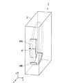
図1は、第1実施形態のX線CT装置を示す構成例を示す図である。図2は、第1実施形態のX線CT装置の一部構成(ガントリ)を示す斜視図である。 FIG. 1 is a diagram illustrating a configuration example of the X-ray CT apparatus according to the first embodiment. FIG. 2 is a perspective view showing a partial configuration (gantry) of the X-ray CT apparatus of the first embodiment.
図1及び図2は、第1実施形態の2管球システムを有するX線CT装置1を示す。X線CT装置1は、大きくは、スキャナ装置11及び画像処理装置(コンソール)12によって構成される。X線CT装置1のスキャナ装置11は、通常は検査室に設置され、患者O(被検体)に関するX線の透過データを生成するために構成される。一方、画像処理装置12は、通常は検査室に隣接する制御室に設置され、透過データに基づく断層像の生成・表示を行なうために構成される。
1 and 2 show an X-ray CT apparatus 1 having a two-tube system of the first embodiment. The X-ray CT apparatus 1 is mainly composed of a scanner device 11 and an image processing device (console) 12. The scanner device 11 of the X-ray CT apparatus 1 is usually installed in an examination room and configured to generate X-ray transmission data related to a patient O (subject). On the other hand, the
X線CT装置1のスキャナ装置11は、ガントリ(架台)21、X線高電圧装置22A,22B、寝台23、及びコントローラ24を備える。さらに、ガントリ21は、X線管31A,31B、絞り32A,32B、X線検出器33A,33B、DAS(data acquisition system)34A,34B、及び回転部35を設ける。なお、X線高電圧装置22A,22Bは、ガントリ21に保持されるものであってもよい。
The scanner device 11 of the X-ray CT apparatus 1 includes a
X線管31A(31B)は、X線高電圧装置22A(22B)から供給された管電圧に応じて金属製のターゲットに電子線を衝突させることでX線を発生させ、X線検出器33A(33B)に向かって照射する。X線管31A(31B)から照射されるX線によって、ファンビームX線やコーンビームX線が形成される。X線管31A(31B)は、X線高電圧装置22A(22B)を介したコントローラ24による制御によって、X線の照射に必要な電力が供給される。ここで、X線管31Aと、X線管31Bとは、ビューが90度ずれているものとして図示するが、その場合に限定するものではない。
The
絞り32A(32B)は、絞り駆動装置(図示しない)によって、X線管31A(31B)から照射されるX線のスライス方向(z軸方向)の照射範囲を調整する。すなわち、絞り駆動装置(図示しない)によって絞り32A(32B)の開口を調整することによって、スライス方向のX線照射範囲を変更できる。
The
X線検出器33A(33B)は、マトリクス状、すなわち、チャンネル方向に複数、及びスライス方向に複数の検出素子を有する2次元アレイ型の検出器(マルチスライス型検出器ともいう。)である。しかも、X線検出器33A(33B)のチャンネル方向は、特に、X線管31A(31B)からのX線ビームの広がり角度を考慮して湾曲を持たせている。なお、X線検出器33A(33B)の全体の形状は、用途によって決まり、平板状であってもよい。患者Oを透過したX線は、33A(33B)により一定時間毎に検出され、アナログ値が検出素子毎に出力される。
The
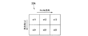
図3は、X線検出器33A,33Bの構成例を示す図である。
FIG. 3 is a diagram illustrating a configuration example of the
図3は、X線検出器33A,33Bが2次元アレイ型の検出器である場合であって、同一ビューにおける、多列・多チャンネルのX線検出器33A,33Bの検出素子をそれぞれ示す。図3に示すように、X線検出器33Bは、X線検出器33Aに対して列方向に検出素子の幅の半個分(1/2)である“d”だけずれるように配置される。すなわち、X線検出器33A,33Bの回転軌道は列方向に検出素子の幅の1/2である“d”だけずれる(図2参照)。
FIG. 3 shows a case where the
このようなX線検出器33A,33Bの構成とすることで、X線CT装置1(図1に図示)は、各ビューにおいて、列方向に2倍で1/2素子単位での透過データを検出することができる。
By adopting such a configuration of the
なお、図3に示すX線検出器33A,33Bにおいて、便宜上、検出素子が平面的に配置されるものとして図示されるが、その場合に限定されるものではない。
In the
図1の説明に戻って、DAS34A(34B)は、リセットされるまでの一定時間の間に、積分値(図示しない)により、X線検出器33A(33B)の検出領域(第1実施形態では1検出素子)に入射したX線を検出する。その結果としてのアナログ値はA/D変換され、デジタル量の検出データ(生データ)として読み出される。 Returning to the description of FIG. 1, the DAS 34 </ b> A (34 </ b> B) detects the detection region (in the first embodiment) of the X-ray detector 33 </ b> A (33 </ b> B) by an integral value (not shown) during a certain time until it is reset. X-rays incident on one detection element) are detected. The resulting analog value is A / D converted and read as digital detection data (raw data).
回転部35は、X線管31A(31B)とX線検出器33A(33B)とを対向させた状態で、X線管31A,31B、絞り32A,32B、X線検出器33A,33B、及びDAS34A,34Bを一体として保持する。回転部35は、回転駆動装置(図示しない)を介したコントローラ24による制御によって、X線管31A,31B、絞り32A,32B、X線検出器33A,33B、及びDAS34A,34Bを一体として患者Oの周りに回転できるように構成されている。なお、回転部35の回転中心軸と平行な方向をz軸方向、そのz軸方向に直交する平面をx軸方向、y軸方向で定義する。
The rotating
X線高電圧装置22A(22B)は、コントローラ24による制御によって、X線の照射に必要な電力をX線管31A(31B)に供給する。
The X-ray
寝台23は、患者Oを載置可能である。寝台23は、寝台駆動装置(図示しない)を介したコントローラ24による制御によって、y軸方向に沿って昇降動されると共に、z軸方向に沿って進入/退避動される。回転部35の中央部分は開口を有し、その開口部の寝台23に載置された患者Oが挿入される。
The
コントローラ24は、図示しないCPU(central processing unit)及びメモリ等を備える。コントローラ24は、画像処理装置12からの指示によって、ガントリ21、X線高電圧装置22A,22B、及び寝台23等の制御を行なってスキャンを実行させる。
The
X線CT装置1の画像処理装置12は、コンピュータをベースとして構成されており、ネットワーク(local area network)Nと相互通信可能である。画像処理装置12は、大きくは、CPU41、メモリ42、HDD(hard disc drive)43、入力装置44、表示装置45、IF(interface)46、及びスキャン制御部47等の基本的なハードウェアから構成される。CPU41は、共通信号伝送路としてのバスを介して、画像処理装置12を構成する各ハードウェア構成要素に相互接続されている。なお、画像処理装置12は、記憶媒体ドライブ48を具備する場合もある。
The
CPU41は、半導体で構成された電子回路が複数の端子を持つパッケージに封入されている集積回路(LSI)の構成をもつ制御装置である。医師等の操作者によって入力装置44が操作等されることにより指令が入力されると、CPU41は、メモリ42に記憶しているプログラムを実行する。又は、CPU41は、HDD43に記憶しているプログラム、ネットワークNから転送されてHDD43にインストールされたプログラム、又は記憶媒体ドライブ48に装着された記録媒体から読み出されてHDD43にインストールされたプログラムを、メモリ42にロードして実行する。
The
メモリ42は、ROM(read only memory)及びRAM(random access memory)等を含む記憶装置である。メモリ42は、IPL(initial program loader)、BIOS(basic input/output system)及びデータを記憶したり、CPU41のワークメモリやデータの一時的な記憶に用いられたりする。
The
HDD43は、磁性体を塗布又は蒸着した金属のディスクが着脱不能で内蔵されている構成をもつ記憶装置である。HDD43は、画像処理装置12にインストールされたプログラム(アプリケーションプログラムの他、OS(operating system)等も含まれる)や、データを記憶する記憶装置である。また、OSに、術者等の操作者に対する表示装置45への情報の表示にグラフィックを多用し、基礎的な操作を入力装置44によって行なうことができるGUI(graphical user interface)を提供させることもできる。
The
入力装置44は、操作者によって操作が可能なポインティングデバイスであり、操作に従った入力信号がCPU41に送られる。
The
表示装置45は、図示しない画像合成回路、VRAM(video random access memory)、及びディスプレイ等を含んでいる。画像合成回路は、画像データに種々のパラメータの文字データ等を合成した合成データを生成する。VRAMは、合成データをディスプレイに展開する。ディスプレイは、液晶ディスプレイやCRT(cathode ray tube)等によって構成され画像を表示する。
The
IF46は、パラレル接続仕様やシリアル接続仕様に合わせたコネクタによって構成される。IF46は、各規格に応じた通信制御を行ない、電話回線等を通じてネットワークNに接続することができる機能を有しており、これにより、X線CT装置1をネットワークN網に接続させる。 The IF 46 is configured by a connector that conforms to a parallel connection specification or a serial connection specification. The IF 46 has a function of performing communication control according to each standard and connecting to the network N through a telephone line or the like, thereby connecting the X-ray CT apparatus 1 to the network N network.
スキャン制御部47は、コントローラ24を制御してコンベンショナルスキャン又はヘリカルスキャンを実行させる機能と、X線検出器33Aの複数の検出素子と、X線検出器33Bの複数の検出素子とでそれぞれ対応する検出素子同士が列方向に検出素子の幅の1/2である“d”(図2に図示)だけずれた第1の生データ(前処理前のデータ)及び第2の生データを、DAS34A,34B(図1に図示)からそれぞれ取得する。
The
スキャン制御部47は、コンベンショナルスキャンでフルスキャン(360度)を実行する場合、コントローラ24を介して回転部35を360度回転させて、X線検出器33A,33Bにそれぞれ360度分の透過データを検出させる。一方、スキャン制御部47は、ハーフスキャン(180度+ファン角)を実行する場合、コントローラ24を介して回転部35を180度回転させて、X線検出器33A,33Bにそれぞれ180度分の透過データを検出させる。
When performing a full scan (360 degrees) as a conventional scan, the
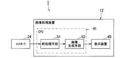
図4は、第1実施形態のX線CT装置1の機能を示すブロック図である。 FIG. 4 is a block diagram illustrating functions of the X-ray CT apparatus 1 according to the first embodiment.
画像処理装置12のCPU41がプログラムを実行することによって、図4に示すように、前処理手段51及び画像生成手段52として機能する。手段51,52は、ソフトウェア的に機能する場合を例に挙げて説明するが、それら手段51,52の一部又は全部は、画像処理装置12にハードウェア的にそれぞれ設けられるものであってもよい。
When the
前処理手段51は、スキャン制御部47(図1に図示)によって取得された第1の生データ及び第2の生データに対して対数変換処理や、感度補正等の補正処理(前処理)を行なって第1の投影データ(再構成前のデータ)及び第2の投影データをそれぞれ生成してHDD43(図1に図示)等の記憶装置に記憶させる機能を有する。また、前処理手段51は、前処理された第1の投影データ及び第2の投影データに対して散乱線の除去処理を行なう機能を有する。
The preprocessing
画像生成手段52は、前処理手段51によって生成された、第1の投影データ及び第2の投影データに基づいて、逐次近似法やフーリエ計算法等の画像再構成処理法により、画像データを生成する機能を有する。画像生成手段52は、生成された画像データを表示装置45に表示させる機能を有する。
The
画像生成手段52は、第1に、スキャン制御部47(図1に図示)によって、同一ビューにおけるX線検出器33A,33B(図1に図示)の列方向の重複部分にX線が入射されるように絞り32A,32B(図1に図示)が制御されるコンベンショナルスキャンが実行される場合、同一ビューの第1の投影データ及び第2の投影データを収集する。そして、画像生成手段52は、第1の投影データ及び第2の投影データに基づいて、1検出素子を列方向に2分割したエレメント毎の検出値を下記式(1)〜(3)を適用して演算して第3の投影データを生成し、複数ビューの第3の投影データに基づいて、画像データを生成する。
In the image generating means 52, first, X-rays are incident on overlapping portions in the column direction of the
図5及び図6は、列方向の空間分解能を説明するための図である。 5 and 6 are diagrams for explaining the spatial resolution in the column direction.
図5は、X線検出器33Aの一部の検出素子e11〜e23を示す。図5によれば、各検出素子e11〜e23の単位でX線が検出される。
FIG. 5 shows some detection elements e11 to e23 of the
図6は、図5に示すX線検出器33Aの一部の検出素子e11〜e23と、X線検出器33Aとビューが同じ場合のX線検出器33Bの一部の検出素子E11〜E13とを示す。図6によれば、X線検出器33Aの検出素子e11を列方向に2分割してエレメントP11,P21を形成することができ、検出素子e21を列方向に2分割してエレメントP31,P41を形成することができる。そして、列方向に最端部のエレメントP11の値が重複部分R外であるから、検出素子e11の検出値からエレメントP21の演算値が次の式(1)で演算でき、検出素子E11の検出値とエレメントP21の値とからエレメントP31の値が次の式(2)で演算でき、検出素子e21の検出値とエレメントP31の演算値とからエレメントP41の値が次の式(3)で演算できる。
6 shows a part of the detection elements e11 to e23 of the
エレメントP21の演算値=検出素子e11の検出値
…(1)
エレメントP31の演算値=検出素子E11の検出値−エレメントP21の演算値
…(2)
エレメントP41の演算値=検出素子e21の検出値とエレメントP31の演算値
…(3)
Calculation value of element P21 = detection value of detection element e11
... (1)
Calculated value of element P31 = detected value of detection element E11−calculated value of element P21
... (2)
Calculation value of element P41 = detection value of detection element e21 and calculation value of element P31
... (3)
図4の説明に戻って、画像生成手段52は、第2に、スキャン制御部47(図1に図示)によって、同一ビューにおけるX線検出器33A,33B(図1に図示)の列方向の重複部分にX線が入射されるように絞り32A,32B(図1に図示)が制御されるコンベンショナルスキャンが実行される場合、第1の投影データに基づく第1のボリュームデータと第2の投影データに基づく第2のボリュームデータとを生成する。そして、画像生成手段52は、第1のボリュームデータ及び第2のボリュームデータに基づいて、1検出素子(ボクセル)を列方向に2分割したエレメント毎の検出値を上記式(1)〜(3)を応用して演算して第3のボリュームデータを生成し、第3のボリュームデータに基づいて、画像データを生成する。
Returning to the description of FIG. 4, the image generating means 52 secondly scans the X-ray detectors 33 </ b> A and 33 </ b> B (shown in FIG. 1) in the same direction by the scan control unit 47 (shown in FIG. 1). When a conventional scan is performed in which the
画像生成手段52は、第3に、スキャン制御部47(図1に図示)によって、コンベンショナルスキャン又はヘリカルスキャンが実行される場合、前処理手段51によって生成された複数ビューの第1の投影データに基づいて第1の画像データを生成し、前処理手段51によって生成された複数ビューの第2の投影データに基づいて第2の画像データを生成し、第1の画像データ及び第2の画像データを加算(加算平均)して第3の画像データを生成する。また、画像生成手段52は、コンベンショナルスキャン又はヘリカルスキャンの場合、前処理手段51によって生成された複数ビューの第1の投影データに基づく第1のボリュームデータと、前処理手段51によって生成された複数ビューの第2の投影データに基づく第2のボリュームデータとを生成し、第1のボリュームデータ及び第2のボリュームデータを加算して第3のボリュームデータを生成してもよい。その場合、第3のボリュームデータに基づいて画像データが生成される。 Thirdly, the image generation means 52 applies the first projection data of the plurality of views generated by the preprocessing means 51 when the conventional scan or the helical scan is executed by the scan control unit 47 (shown in FIG. 1). 1st image data is produced | generated based on 2nd projection data based on the 2nd projection data of the several view produced | generated by the pre-processing means 51, 1st image data and 2nd image data Are added (average addition) to generate third image data. In the case of a conventional scan or a helical scan, the image generation means 52 includes a first volume data based on the first projection data of a plurality of views generated by the preprocessing means 51 and a plurality of pieces generated by the preprocessing means 51. Second volume data based on the second projection data of the view may be generated, and the third volume data may be generated by adding the first volume data and the second volume data. In that case, image data is generated based on the third volume data.
第1実施形態のX線CT装置1によると、検出素子の列方向の空間分解能を向上させることができる。 According to the X-ray CT apparatus 1 of the first embodiment, the spatial resolution in the column direction of the detection elements can be improved.
(第2実施形態)
第2実施形態のX線CT装置は、第1実施形態のX線CT装置と異なり、2個のX線検出器の回転軌道を一致させる構成を有し、それぞれのX線検出器の複数の検出素子を1検出領域とするものである。
(Second Embodiment)
Unlike the X-ray CT apparatus of the first embodiment, the X-ray CT apparatus of the second embodiment has a configuration in which the rotation trajectories of the two X-ray detectors coincide with each other. The detection element is one detection region.
図7は、第1実施形態のX線CT装置を示す構成例を示す図である。図8は、第2実施形態のX線CT装置の一部構成(ガントリ)を示す斜視図である。 FIG. 7 is a diagram illustrating a configuration example of the X-ray CT apparatus according to the first embodiment. FIG. 8 is a perspective view showing a partial configuration (gantry) of the X-ray CT apparatus of the second embodiment.
図7及び図8は、第2実施形態の2管球システムを有するX線CT装置1aを示す。X線CT装置1aは、大きくは、スキャナ装置11a及び画像処理装置12によって構成される。X線CT装置1aのスキャナ装置11aは、通常は検査室に設置され、患者Oに関するX線の透過データを生成するために構成される。一方、画像処理装置12は、通常は検査室に隣接する制御室に設置され、透過データに基づく断層像の生成・表示を行なうために構成される。
7 and 8 show an X-ray CT apparatus 1a having the two-tube system of the second embodiment. The X-ray CT apparatus 1a is mainly composed of a
X線CT装置1aのスキャナ装置11aは、ガントリ21a、X線高電圧装置22A,22C、寝台23、及びコントローラ24を備える。さらに、ガントリ21aは、X線管31A,31C、絞り32A,32C、X線検出器33A,33C、DAS34A,34C、回転部35、及び加算・スイッチ回路36A,36Cを設ける。なお、X線高電圧装置22A,22Cは、ガントリ21aに保持されるものであってもよい。
The
なお、図7及び図8に示すX線CT装置1aにおいて、図1及び図2に示すX線CT装置1と同一部材には同一符号を付して説明を省略する。 In the X-ray CT apparatus 1a shown in FIGS. 7 and 8, the same members as those in the X-ray CT apparatus 1 shown in FIGS.
X線管31Cは、X線高電圧装置22Cから供給された管電圧に応じて金属製のターゲットに電子線を衝突させることでX線を発生させ、X線検出器33Cに向かって照射する。X線管31Cから照射されるX線によって、ファンビームX線やコーンビームX線が形成される。X線管31Cは、X線高電圧装置22Cを介したコントローラ24による制御によって、X線の照射に必要な電力が供給される。ここで、X線管31Aと、X線管31Cとは、ビューが90度ずれているものとして図示するが、その場合に限定するものではない。
The X-ray tube 31C generates X-rays by causing an electron beam to collide with a metal target in accordance with the tube voltage supplied from the X-ray high-voltage device 22C, and irradiates the X-ray detector 33C. Fan beam X-rays and cone beam X-rays are formed by X-rays emitted from the X-ray tube 31C. The X-ray tube 31C is supplied with electric power necessary for X-ray irradiation under the control of the
絞り32Cは、絞り駆動装置(図示しない)によって、X線管31Cから照射されるX線のスライス方向(z軸方向)の照射範囲を調整する。すなわち、絞り駆動装置(図示しない)によって絞り32Cの開口を調整することによって、スライス方向のX線照射範囲を変更できる。
The
X線検出器33Cは、マトリクス状、すなわち、チャンネル方向に複数、及びスライス方向に複数の検出素子を有する2次元アレイ型の検出器である。しかも、X線検出器33Cのチャンネル方向は、特に、X線管31CからのX線ビームの広がり角度を考慮して湾曲を持たせている。なお、X線検出器33Cの全体の形状は、用途によって決まり、平板状であってもよい。 The X-ray detector 33C is a two-dimensional array type detector having a matrix, that is, a plurality of detection elements in the channel direction and a plurality of detection elements in the slice direction. In addition, the channel direction of the X-ray detector 33C is curved in consideration of the spread angle of the X-ray beam from the X-ray tube 31C. Note that the overall shape of the X-ray detector 33C depends on the application and may be a flat plate shape.
DAS34Cは、リセットされるまでの一定時間の間に、積分器(図示しない)により、X線検出器33Cの各検出領域に入射したX線を検出する。その結果としてのアナログ値はA/D変換され、デジタル量の検出データ(生データ)として読み出される。
The
加算・スイッチ回路36A(36C)は、X線検出器33A(33C)とDAS34A(34C)との間に配設される。
The addition /
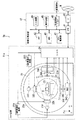
図9は、加算・スイッチ回路36A(36C)の構成を示す側面図である。
FIG. 9 is a side view showing the configuration of the addition /
図9に示すように、X線検出器33A(33C)の細分化された検出素子と、DAS34A(34C)との間には加算・スイッチ回路36A(36C)が備えられる。加算・スイッチ回路36A(36C)を介したコントローラ24(図7に図示)の制御によって、X線検出器33A(33C)の検出素子f11の検出信号は、そのままDAS34A(34C)に入力されたり(検出領域:1検出素子)、隣の検出素子f12の検出信号に加算されてDAS34A(34C)に入力されたり(検出領域:2検出素子)する。また、加算・スイッチ回路36A(36C)を介したコントローラ24(図7に図示)の制御によって、X線検出器33A(33C)の検出素子f12の検出信号は、そのままDAS34A(34C)に入力されたり(検出領域:1検出素子)、隣の検出素子f11の検出信号に加算されてDAS34A(34C)に入力されたり(検出領域:2検出素子)、隣の検出素子f13の検出信号に加算されてDAS34A(34C)に入力されたり(検出領域:2検出素子)する。
As shown in FIG. 9, an adder /
図10は、第2実施形態のX線CT装置1aにおいて、列方向の空間分解能を向上させるための方法を説明するための図である。 FIG. 10 is a diagram for explaining a method for improving the spatial resolution in the column direction in the X-ray CT apparatus 1a of the second embodiment.
図10は、X線検出器33Aの一部の検出素子f11〜f44と、X線検出器33Aとビューが同じ場合のX線検出器33Cの一部の検出素子F11〜F44とを示す。
FIG. 10 shows some detection elements f11 to f44 of the
加算・スイッチ回路36A,36C(図7及び図9に図示)を介して、図10に示すように、X線検出器33Aの2個の検出素子f11,f21を検出領域として検出素子f11,f21の検出信号(検出素子f11は重複部分R外であるので「0」)を加算することで、検出素子f11,f21を1つの検出素子e11(図6に図示)とみなして第1の生データを生成することができ、X線検出器33Cの2個の検出素子F21,F31を検出領域として検出素子F21,F31の検出信号を加算することで、検出素子F21,F31を1つの検出素子E11(図6に図示)とみなして第2の生データを生成することができる。すなわち、第2実施形態のX線CT装置1aでは、2個のX線検出器33A,33Cの回転軌道が一致するにもかかわらず、2個のX線検出器の回転軌道がずれている第1実施形態のX線CT装置1と同様に考えて列方向の空間分解能を検出領域の2倍に向上させることができる。
As shown in FIG. 10, via the addition /
ここで、X線検出器33Aのチャンネル方向に複数の検出素子からなる複数の検出領域と、X線検出器33Cのチャンネル方向に複数の検出素子からなる複数の検出領域とでそれぞれ対応する検出領域同士がチャンネル方向に検出領域の幅の1/2分ずれるようにしてもよい。
Here, detection areas corresponding to a plurality of detection areas composed of a plurality of detection elements in the channel direction of the
図11は、第2実施形態のX線CT装置1aにおいて、チャンネル方向の空間分解能を向上させるための方法を説明するための図である。 FIG. 11 is a diagram for explaining a method for improving the spatial resolution in the channel direction in the X-ray CT apparatus 1a of the second embodiment.
図11は、X線検出器33Aの一部の検出素子f11〜f44と、X線検出器33Aとビューが同じ場合のX線検出器33Cの一部の検出素子F11〜F44とを示す。
FIG. 11 shows some detection elements f11 to f44 of the
加算・スイッチ回路36A,36C(図7及び図9に図示)を介して、図11に示すように、X線検出器33Aの2個の検出素子f11,f12を検出領域として検出素子f11,f12の検出信号(検出素子f11は重複部分R外であるので「0」)を加算することで、検出素子f11,f12を1つの検出素子とみなして第1の生データを生成することができ、X線検出器33Cの2個の検出素子F12,F13を検出領域として検出素子F12,F13の検出信号を加算することで、検出素子F12,F13を1つの検出素子とみなして第2の生データを生成することができる。すなわち、第2実施形態のX線CT装置1aでは、2個のX線検出器33A,33Cの回転軌道が一致するにもかかわらず、2個のX線検出器の回転軌道がずれている第1実施形態のX線CT装置1と同様に考えてチャンネル方向の空間分解能を検出領域の2倍に向上させることもできる。
As shown in FIG. 11, via the addition /
なお、図10及び図11では、2検出素子を1検出領域とし、2検出素子の単位でX線を検出するものとして説明したが、その場合に限定されるものではない。 In FIGS. 10 and 11, two detection elements are used as one detection region, and X-rays are detected in units of two detection elements. However, the present invention is not limited to this case.
図7及び図8の説明に戻って、回転部35は、X線管31A(31C)とX線検出器33A(33C)とを対向させた状態で、X線管31A,31C、絞り32A,32C、X線検出器33A,33C、DAS34A,34C、及び加算・スイッチ回路36A,36Cを一体として保持する。回転部35は、回転駆動装置(図示しない)を介したコントローラ24による制御によって、X線管31A,31C、絞り32A,32C、X線検出器33A,33C、DAS34A,34C、及び加算・スイッチ回路36A,36Cを一体として患者Oの周りに回転できるように構成されている。なお、回転部35の回転中心軸と平行な方向をz軸方向、そのz軸方向に直交する平面をx軸方向、y軸方向で定義する。
Returning to the description of FIGS. 7 and 8, the rotating
X線高電圧装置22Cは、コントローラ24による制御によって、X線の照射に必要な電力をX線管31Cに供給する。
The X-ray high voltage device 22C supplies power necessary for X-ray irradiation to the X-ray tube 31C under the control of the
図12は、第2実施形態のX線CT装置1aの機能を示すブロック図である。 FIG. 12 is a block diagram showing functions of the X-ray CT apparatus 1a of the second embodiment.
画像処理装置12のCPU41がプログラムを実行することによって、図10に示すように、前処理手段51及び画像生成手段52を有する。なお、図12に示す第2実施形態のX線CT装置1aにおいて、図4に示す第1実施形態のX線CT装置1と同一部材には同一符号を付して説明を省略する。
As the
第2実施形態のX線CT装置1aによると、検出器の列方向の空間分解能を向上させることができる。また、第2実施形態のX線CT装置1aによると、2管球システムにおいても、検出器のチャンネル方向の空間分解能を向上させることができる。 According to the X-ray CT apparatus 1a of the second embodiment, the spatial resolution in the column direction of the detector can be improved. Moreover, according to the X-ray CT apparatus 1a of the second embodiment, the spatial resolution in the channel direction of the detector can be improved even in the two-tube system.
なお、本実施形態のX線CT装置1,1aは、フォトンカウンティング(光子計数)型のX線CT装置であってもよい。その場合、X線検出器33A〜33Cは、患者Oを透過したX線を、X線検出器33A〜33CによりX線光子(粒子)として一定時間毎に検出し、光子エネルギーに応じたアナログ値を検出素子(画素)毎に出力する。そして、DAS34A〜34Cは、リセットされるまでの一定時間の間に、複数のカウンタ(図示しない)により、X線検出器33A〜33Cの検出領域(第1実施形態では1画素)で入射したX線粒子の数をカウンタの段数に応じたエネルギー領域毎にカウントする。その結果としてのカウント値は、複数のカウンタからデジタル量の検出データ(生データ)として読み出される。データ読出しは、ASIC層内に画素毎に行なわれる。
Note that the X-ray CT apparatuses 1 and 1a of the present embodiment may be photon counting (photon counting) type X-ray CT apparatuses. In that case, the
以上、本発明のいくつかの実施形態を説明したが、これらの実施形態は、例として提示したものであり発明の範囲を限定することは意図していない。これら新規な実施形態は、その他の様々な形態で実施されることが可能であり、発明の要旨を逸脱しない範囲で種々の省略、置き換え、変更を行なうことができる。これらの実施形態やその変形は、発明の範囲や要旨に含まれるとともに、特許請求の範囲に記載された発明とその均等の範囲に含まれる。 Although several embodiments of the present invention have been described above, these embodiments are presented as examples and are not intended to limit the scope of the invention. These novel embodiments can be implemented in various other forms, and various omissions, replacements, and changes can be made without departing from the scope of the invention. These embodiments and modifications thereof are included in the scope and gist of the invention, and are included in the invention described in the claims and the equivalents thereof.
1,1a X線CT装置
11,11a スキャナ装置
12 画像処理装置
31A,31B,31C X線管
32A,32B,32C 絞り
33A,33B,33C X線検出器
34A,34B,34C DAS
36A,36C 加算・スイッチ回路
41 CPU
45 表示装置
51 前処理手段
52 画像生成手段
1, 1a
36A, 36C Addition /
45
Claims (6)
チャンネル方向及び列方向に複数の第1検出素子を備え、前記第1のX線を検出する第1の検出器と、
第2のX線を発する第2のX線源と、
チャンネル方向及び列方向に複数の第2検出素子を備え、前記第2のX線を検出する第2の検出器と、
前記第1及び第2のX線源と前記第1及び第2の検出器とを制御してスキャンを実行し、1又は列方向に複数の第1検出素子からなる複数の第1検出領域と、1又は列方向に複数の第2検出素子からなる複数の第2検出領域とでそれぞれ対応する検出領域同士が前記列方向に前記検出領域の1/2ずれた、前記第1検出領域の第1のデータと前記第2検出領域の第2のデータを取得するスキャン実行手段と、
前記取得された第1及び第2のデータに基づいて画像データを生成する画像生成手段と、
を有するX線CT装置。 A first X-ray source emitting a first X-ray;
A first detector that includes a plurality of first detection elements in a channel direction and a column direction, and detects the first X-ray;
A second X-ray source emitting a second X-ray;
A second detector that includes a plurality of second detection elements in a channel direction and a column direction, and detects the second X-ray;
A plurality of first detection regions comprising a plurality of first detection elements in one or a column direction by controlling the first and second X-ray sources and the first and second detectors to perform scanning; Detection regions corresponding to a plurality of second detection regions made of a plurality of second detection elements in one or the column direction are shifted from each other by a half of the detection region in the column direction. Scan execution means for acquiring the first data and the second data of the second detection area;
Image generating means for generating image data based on the acquired first and second data;
X-ray CT apparatus.
前記第2の検出器の回転軌道は、前記第1の検出器に対して前記列方向に、前記検出素子の1/2ずれるように配置される請求項1に記載のX線CT装置。 When the first and second detection regions are the first first and second detection elements,
2. The X-ray CT apparatus according to claim 1, wherein the rotation trajectory of the second detector is arranged so as to be shifted by a half of the detection element in the column direction with respect to the first detector.
前記スキャン実行手段は、前記スキャンとしてコンベンショナルスキャンを実行し、
前記画像生成手段は、前記コンベンショナルスキャンによって同一ビューにおける前記取得された第1及び第2のデータに基づいて1検出素子を列方向に2分割したエレメント毎のデータを演算し、そのデータに基づいて前記画像データを生成する請求項2に記載のX線CT装置。 First and second apertures for controlling the first X-ray and the second X-ray to be incident on overlapping portions in the column direction of the first and second detectors in the same view, respectively. Have
The scan execution means executes a conventional scan as the scan,
The image generation means calculates data for each element obtained by dividing one detection element into two in the column direction based on the acquired first and second data in the same view by the conventional scan, and based on the data The X-ray CT apparatus according to claim 2, wherein the image data is generated.
前記画像生成手段は、前記スキャンによって同一ビューにおける前記取得された第1のデータに基づいて第1の画像データを生成し、前記第2のデータに基づいて第2の画像データを生成し、前記第1及び第2の画像データを加算して第3の画像データを生成する請求項2に記載のX線CT装置。 The scan execution means executes a conventional scan or a helical scan as the scan,
The image generation means generates first image data based on the acquired first data in the same view by the scan, generates second image data based on the second data, and The X-ray CT apparatus according to claim 2, wherein the third image data is generated by adding the first and second image data.
前記第2の検出器の回転軌道は、前記第1の検出器の回転軌道と一致するように配置される請求項1に記載のX線CT装置。 When the first and second detection regions are the plurality of first and second detection elements,
The X-ray CT apparatus according to claim 1, wherein a rotation trajectory of the second detector is arranged to coincide with a rotation trajectory of the first detector.
チャンネル方向及び列方向に複数の第1検出素子を備え、前記第1のX線を検出する第1の検出器と、
第2のX線を発する第2のX線源と、
チャンネル方向及び列方向に複数の第2検出素子を備え、前記第2のX線を検出する第2の検出器と、
前記第1及び第2のX線源と前記第1及び第2の検出器とを制御してスキャンを実行し、チャンネル方向に複数の第1検出素子からなる複数の第1検出領域と、チャンネル方向に複数の第2検出素子からなる複数の第2検出領域とでそれぞれ対応する検出領域同士が前記チャンネル方向に前記検出領域の1/2ずれた、前記第1検出領域の第1のデータと前記第2検出領域の第2のデータを取得するスキャン実行手段と、
前記取得された第1及び第2のデータに基づいて画像データを生成する画像生成手段と、
を有するX線CT装置。 A first X-ray source emitting a first X-ray;
A first detector that includes a plurality of first detection elements in a channel direction and a column direction, and detects the first X-ray;
A second X-ray source emitting a second X-ray;
A second detector that includes a plurality of second detection elements in a channel direction and a column direction, and detects the second X-ray;
A plurality of first detection regions each including a plurality of first detection elements in a channel direction, the first and second X-ray sources and the first and second detectors controlled to perform scanning, and a channel The first data in the first detection area, the detection areas corresponding to each other in a plurality of second detection areas made of a plurality of second detection elements in the direction are shifted from each other by a half of the detection area in the channel direction; Scan execution means for acquiring second data of the second detection region;
Image generating means for generating image data based on the acquired first and second data;
X-ray CT apparatus.
Priority Applications (3)
| Application Number | Priority Date | Filing Date | Title |
|---|---|---|---|
| JP2013109143A JP2014226376A (en) | 2013-05-23 | 2013-05-23 | X-ray ct device |
| PCT/JP2014/063714 WO2014189133A1 (en) | 2013-05-23 | 2014-05-23 | X-ray ct device |
| US14/877,311 US10258296B2 (en) | 2013-05-23 | 2015-10-07 | X-ray CT apparatus including processing circuitry to improve a spatial resolution in a row direction and a channel direction |
Applications Claiming Priority (1)
| Application Number | Priority Date | Filing Date | Title |
|---|---|---|---|
| JP2013109143A JP2014226376A (en) | 2013-05-23 | 2013-05-23 | X-ray ct device |
Publications (1)
| Publication Number | Publication Date |
|---|---|
| JP2014226376A true JP2014226376A (en) | 2014-12-08 |
Family
ID=51933683
Family Applications (1)
| Application Number | Title | Priority Date | Filing Date |
|---|---|---|---|
| JP2013109143A Ceased JP2014226376A (en) | 2013-05-23 | 2013-05-23 | X-ray ct device |
Country Status (3)
| Country | Link |
|---|---|
| US (1) | US10258296B2 (en) |
| JP (1) | JP2014226376A (en) |
| WO (1) | WO2014189133A1 (en) |
Families Citing this family (2)
| Publication number | Priority date | Publication date | Assignee | Title |
|---|---|---|---|---|
| EP2914179A1 (en) * | 2012-11-02 | 2015-09-09 | Analogic Corporation | Volumetric and projection image generation |
| JP2014230600A (en) * | 2013-05-28 | 2014-12-11 | 株式会社東芝 | X-ray ct apparatus, and x-ray detector for x-ray ct apparatus |
Citations (2)
| Publication number | Priority date | Publication date | Assignee | Title |
|---|---|---|---|---|
| JP2004325183A (en) * | 2003-04-23 | 2004-11-18 | M & C:Kk | Radiation detection method, radiation detector, and radiation imaging system with this detector loaded thereon |
| JP2006187453A (en) * | 2005-01-06 | 2006-07-20 | Ge Medical Systems Global Technology Co Llc | X-ray ct apparatus |
Family Cites Families (75)
| Publication number | Priority date | Publication date | Assignee | Title |
|---|---|---|---|---|
| JP4054402B2 (en) * | 1997-04-25 | 2008-02-27 | 株式会社東芝 | X-ray tomography equipment |
| JPH06169911A (en) | 1992-12-04 | 1994-06-21 | Toshiba Corp | X-ray computer-aided tomography system |
| JP3340203B2 (en) | 1993-09-17 | 2002-11-05 | 株式会社東芝 | X-ray CT system |
| US6421412B1 (en) * | 1998-12-31 | 2002-07-16 | General Electric Company | Dual cardiac CT scanner |
| US6363134B1 (en) * | 1999-01-13 | 2002-03-26 | Kabushiki Kaisha Toshiba | X-ray computed tomography apparatus |
| JP4267180B2 (en) * | 2000-06-07 | 2009-05-27 | 株式会社日立メディコ | X-ray CT system |
| DE60027930T2 (en) * | 2000-09-28 | 2007-01-25 | Koninklijke Philips Electronics N.V. | CT SCANNER WITH TIME COHERENT LARGE COVER |
| JP2002301056A (en) * | 2001-04-04 | 2002-10-15 | Toshiba Medical System Co Ltd | X-ray ct apparatus and x-ray detector |
| US6834097B2 (en) * | 2001-10-05 | 2004-12-21 | Kabushiki Kaisha Toshiba | X-ray CT apparatus and X-ray CT imaging method |
| US7085343B2 (en) * | 2001-10-18 | 2006-08-01 | Kabushiki Kaisha Toshiba | X-ray computed tomography apparatus |
| JP4088058B2 (en) * | 2001-10-18 | 2008-05-21 | 株式会社東芝 | X-ray computed tomography system |
| US6922457B2 (en) * | 2001-11-29 | 2005-07-26 | Kabushiki Kaisha Toshiba | Computer tomography apparatus |
| EP2915488B1 (en) * | 2002-03-19 | 2019-06-05 | Medtronic Navigation, Inc. | Computer tomography with a detector following the movement of a pivotable x-ray source |
| JP2004000356A (en) | 2002-06-03 | 2004-01-08 | Hitachi Medical Corp | Multi-slice x-ray ct apparatus and method therefor |
| US6819738B2 (en) * | 2002-08-15 | 2004-11-16 | Ge Medical Systems Global Technology Company, Llc | Hybrid scintillator/photo sensor & direct conversion detector |
| JP4314008B2 (en) * | 2002-10-01 | 2009-08-12 | 株式会社東芝 | X-ray CT scanner |
| DE10302565A1 (en) * | 2003-01-22 | 2004-08-12 | Siemens Ag | Computer tomography unit has at least two beam detector combinations the measurement field areas of which can be set to different sizes |
| JP4545144B2 (en) * | 2003-03-13 | 2010-09-15 | コーニンクレッカ フィリップス エレクトロニクス エヌ ヴィ | Computer controlled tomographic imaging system |
| WO2005004722A2 (en) * | 2003-07-15 | 2005-01-20 | Koninklijke Philips Electronics N.V. | Computed tomography scanner with large gantry bore |
| JP3961468B2 (en) * | 2003-09-19 | 2007-08-22 | ジーイー・メディカル・システムズ・グローバル・テクノロジー・カンパニー・エルエルシー | Radiation computed tomography apparatus and radiation detector used therefor |
| DE10354214A1 (en) * | 2003-11-20 | 2005-06-02 | Siemens Ag | A method of generating tomographic slices of a periodically moving object having a plurality of focus-detector combinations |
| DE10354900A1 (en) * | 2003-11-24 | 2005-06-30 | Siemens Ag | A method of generating tomographic slices of a periodically moving object having a plurality of focus-detector combinations |
| US7280631B2 (en) * | 2003-11-26 | 2007-10-09 | General Electric Company | Stationary computed tomography system and method |
| DE102004028124B4 (en) * | 2004-06-09 | 2008-08-07 | Siemens Ag | Multi-mode imaging tomography device and method for changing the operating mode of the tomographic device |
| DE102004030549A1 (en) * | 2004-06-24 | 2006-01-19 | Siemens Ag | Imaging tomography device with at least two mutually fixed recording systems and method for such a tomography device for determining the arrangement of the recording systems |
| DE102004030550A1 (en) * | 2004-06-24 | 2006-01-19 | Siemens Ag | Imaging tomography apparatus with at least two system angles arranged recording systems and method for such a tomography device for determining the system angle of the recording systems |
| CN100393281C (en) * | 2004-07-23 | 2008-06-11 | 株式会社东芝 | X-ray computed tomography apparatus |
| US7103138B2 (en) * | 2004-08-24 | 2006-09-05 | The Board Of Trustees Of The Leland Stanford Junior University | Sampling in volumetric computed tomography |
| DE102004042491B4 (en) * | 2004-08-31 | 2009-07-09 | Siemens Ag | A method for generating tomographic slice images of an examination subject with at least two angularly offset beams and computed tomography device for performing this method |
| US7194061B2 (en) * | 2004-09-14 | 2007-03-20 | Kabushiki Kaisha Toshiba | X-ray computer tomography apparatus |
| JP4594699B2 (en) * | 2004-10-29 | 2010-12-08 | 株式会社東芝 | X-ray computed tomography system |
| EP1701307B1 (en) * | 2005-03-07 | 2010-04-21 | Kabushiki Kaisha Toshiba | X-ray CT apparatus and data detecting method of X-ray CT apparatus |
| US7440547B2 (en) * | 2005-04-15 | 2008-10-21 | Kabushiki Kaisha Toshiba | CT scanner |
| EP1882449A4 (en) * | 2005-05-18 | 2010-05-05 | Hitachi Medical Corp | Radiograph and image processing program |
| US7535987B2 (en) * | 2005-06-30 | 2009-05-19 | Kabushiki Kaisha Toshiba | X-ray CT apparatus |
| DE102005034876B3 (en) * | 2005-07-26 | 2007-04-05 | Siemens Ag | Method for producing computer tomographic images by a CT with at least two angularly offset radiation sources |
| DE102005037368A1 (en) * | 2005-08-08 | 2007-02-15 | Siemens Ag | Computer-tomographic picture evaluating method, involves supplementing integral attenuation value of ray cone with virtual evaluated integral attenuation value, and reconstructing local attenuation value of objects from supplemented value |
| JP4701038B2 (en) * | 2005-08-12 | 2011-06-15 | ジーイー・メディカル・システムズ・グローバル・テクノロジー・カンパニー・エルエルシー | X-ray CT system |
| DE102005048397A1 (en) * | 2005-10-10 | 2007-04-12 | Siemens Ag | Method for radiation correction of a CT system |
| US7831012B2 (en) * | 2006-02-09 | 2010-11-09 | L-3 Communications Security and Detection Systems Inc. | Radiation scanning systems and methods |
| EP1825811B1 (en) * | 2006-02-27 | 2015-08-26 | Kabushiki Kaisha Toshiba | Image display apparatus and x-ray computed tomography apparatus |
| DE102006019920B4 (en) * | 2006-04-28 | 2008-04-10 | Siemens Ag | Method for scatter-correction of a CT system with at least two angularly offset focus-detector systems and X-ray CT system |
| DE102006019923A1 (en) * | 2006-04-28 | 2007-11-15 | Siemens Ag | Method for scattered radiation correction in X-ray CT and X-ray CT for the application of this method |
| DE102006027221B4 (en) * | 2006-06-12 | 2008-12-24 | Siemens Ag | Medical imaging device with two detector systems |
| US7706499B2 (en) * | 2006-08-30 | 2010-04-27 | General Electric Company | Acquisition and reconstruction of projection data using a stationary CT geometry |
| US7616731B2 (en) * | 2006-08-30 | 2009-11-10 | General Electric Company | Acquisition and reconstruction of projection data using a stationary CT geometry |
| US7835486B2 (en) * | 2006-08-30 | 2010-11-16 | General Electric Company | Acquisition and reconstruction of projection data using a stationary CT geometry |
| US8488736B2 (en) * | 2006-09-19 | 2013-07-16 | General Electric Company | Stacked flat panel x-ray detector assembly and method of making same |
| US8483352B2 (en) * | 2006-09-19 | 2013-07-09 | General Electric Company | Stacked x-ray detector assembly and method of making same |
| DE102006051475A1 (en) * | 2006-10-31 | 2008-05-08 | Siemens Ag | Movement and resting phases determining method for e.g. beating heart of patient, involves closing equivalent and rectified line radiations based on angle position of x-ray tubes to relative movement or resting of heart between time points |
| US7428292B2 (en) * | 2006-11-24 | 2008-09-23 | General Electric Company | Method and system for CT imaging using multi-spot emission sources |
| US7388940B1 (en) * | 2006-11-24 | 2008-06-17 | General Electric Company | Architectures for cardiac CT based on area x-ray sources |
| DE102006056884A1 (en) * | 2006-12-01 | 2008-06-05 | Siemens Ag | Cardio-computer tomography examination implementation method for patient, involves scanning patient at position by x-ray tubes without position changing of housing till data for projections over specific range are collected from heart phase |
| DE102007008118B4 (en) * | 2007-02-19 | 2011-02-03 | Siemens Ag | A method for generating tomographic images with an X-ray computed tomography system with scattered radiation correction |
| JP2008237886A (en) * | 2007-02-28 | 2008-10-09 | Toshiba Corp | X-ray ct device and method of controlling the same |
| US7869561B2 (en) * | 2007-04-10 | 2011-01-11 | Arineta Ltd. | Cone-beam CT |
| US8189736B2 (en) * | 2007-08-06 | 2012-05-29 | Hitachi Medical Corporation | X-ray CT apparatus |
| US7433443B1 (en) * | 2007-08-29 | 2008-10-07 | General Electric Company | System and method of CT imaging with second tube/detector patching |
| JP5052281B2 (en) * | 2007-10-02 | 2012-10-17 | 株式会社東芝 | Method for estimating scattered ray intensity distribution in X-ray CT and X-ray CT apparatus |
| US7801265B2 (en) * | 2007-11-23 | 2010-09-21 | Mayo Foundation For Medical Education And Research | System and method for creating mixed image from dual-energy CT data |
| US7949089B2 (en) * | 2008-04-10 | 2011-05-24 | Arineta Ltd. | Apparatus and method for tracking feature's position in human body |
| DE102008030552A1 (en) * | 2008-06-27 | 2009-12-31 | Siemens Aktiengesellschaft | A method for generating image data on a virtually predefinable x-ray tube voltage from first and second CT image data |
| JP5159543B2 (en) * | 2008-09-30 | 2013-03-06 | 株式会社東芝 | X-ray CT system |
| JP5537132B2 (en) * | 2008-12-11 | 2014-07-02 | 株式会社東芝 | X-ray computed tomography apparatus, medical image processing apparatus, and medical image processing program |
| JP2011104075A (en) * | 2009-11-17 | 2011-06-02 | Toshiba Corp | X-ray ct apparatus |
| US8594272B2 (en) * | 2010-03-19 | 2013-11-26 | Triple Ring Technologies, Inc. | Inverse geometry volume computed tomography systems |
| WO2012063957A1 (en) * | 2010-11-12 | 2012-05-18 | 株式会社東芝 | Diagnostic imaging device and method |
| EP2674787A1 (en) * | 2010-12-21 | 2013-12-18 | Telesystems Co., Ltd. | Radiation detector, and radiation imaging apparatus provided with detector |
| US8774351B2 (en) * | 2011-04-05 | 2014-07-08 | Triple Ring Technologies, Inc. | Method and apparatus for advanced X-ray imaging systems |
| US9380987B2 (en) * | 2011-12-12 | 2016-07-05 | Hitachi Medical Corporation | X-ray CT device |
| JP6195337B2 (en) * | 2012-02-24 | 2017-09-13 | 東芝メディカルシステムズ株式会社 | X-ray CT system |
| US9818182B2 (en) * | 2012-06-20 | 2017-11-14 | Hitachi, Ltd. | X-ray CT device |
| WO2014034888A1 (en) * | 2012-08-30 | 2014-03-06 | 株式会社東芝 | X-ray ct apparatus, image processing apparatus, and image processing method |
| WO2014106956A1 (en) * | 2013-01-07 | 2014-07-10 | 株式会社東芝 | X-ray computed tomography device and medical image processing device |
| DE102013203541A1 (en) * | 2013-03-01 | 2014-09-04 | Siemens Aktiengesellschaft | X-ray CT scan and dual source CT system |
-
2013
- 2013-05-23 JP JP2013109143A patent/JP2014226376A/en not_active Ceased
-
2014
- 2014-05-23 WO PCT/JP2014/063714 patent/WO2014189133A1/en active Application Filing
-
2015
- 2015-10-07 US US14/877,311 patent/US10258296B2/en active Active
Patent Citations (2)
| Publication number | Priority date | Publication date | Assignee | Title |
|---|---|---|---|---|
| JP2004325183A (en) * | 2003-04-23 | 2004-11-18 | M & C:Kk | Radiation detection method, radiation detector, and radiation imaging system with this detector loaded thereon |
| JP2006187453A (en) * | 2005-01-06 | 2006-07-20 | Ge Medical Systems Global Technology Co Llc | X-ray ct apparatus |
Also Published As
| Publication number | Publication date |
|---|---|
| US10258296B2 (en) | 2019-04-16 |
| US20160022237A1 (en) | 2016-01-28 |
| WO2014189133A1 (en) | 2014-11-27 |
Similar Documents
| Publication | Publication Date | Title |
|---|---|---|
| US10219775B2 (en) | Photon-counting X-ray CT apparatus and image processing apparatus | |
| JP2016041387A (en) | Image display device | |
| JP3961468B2 (en) | Radiation computed tomography apparatus and radiation detector used therefor | |
| JP5761972B2 (en) | X-ray CT system | |
| JP6494982B2 (en) | X-ray computed tomography apparatus, image processing apparatus, and image processing program | |
| JP2007300964A (en) | Radiographic equipment and radiography method | |
| US11244480B2 (en) | Medical information processing apparatus | |
| JP2016147062A (en) | X-ray computer tomographic imaging device and medical image processor | |
| JP2007252898A (en) | Image display and x-ray ct scanner | |
| US10682104B2 (en) | Computed tomography recording with different sets of energy thresholds | |
| WO2014189133A1 (en) | X-ray ct device | |
| JP7242410B2 (en) | MEDICAL IMAGE PROCESSING APPARATUS, X-RAY CT APPARATUS, AND LEARNING DATA GENERATION METHOD | |
| US8976923B2 (en) | Multislice CT apparatus and method for data preprocessing | |
| JP2020022689A (en) | Medical image processing apparatus and X-ray CT apparatus | |
| JP2017086872A (en) | Photon counting type X-ray CT apparatus and image processing apparatus | |
| JP2020103571A (en) | Medical processing device and X-ray diagnostic system | |
| US11559269B2 (en) | X-ray imaging apparatus, medical information processing apparatus, X-ray detector, and correction method of X-ray detector | |
| EP4092617A2 (en) | Medical information processing method and medical image processing apparatus | |
| US11478203B2 (en) | X-ray computed tomography apparatus and imaging condition management apparatus | |
| US20230404514A1 (en) | Medical data processing method, model generating method, and medical data processing apparatus | |
| JP6333551B2 (en) | Medical image diagnostic apparatus and image processing apparatus | |
| US20240065654A1 (en) | Photon counting x-ray image diagnosis apparatus and method for generating calibration data for pileup correction | |
| JP7487683B2 (en) | Radiation image generating method and radiation image capturing device | |
| JP6643019B2 (en) | Image processing apparatus, image processing method, and program | |
| JP2020089594A (en) | Medical image processing system, medical image processing device, and medical image processing method |
Legal Events
| Date | Code | Title | Description |
|---|---|---|---|
| A711 | Notification of change in applicant |
Free format text: JAPANESE INTERMEDIATE CODE: A711 Effective date: 20160506 |
|
| A621 | Written request for application examination |
Free format text: JAPANESE INTERMEDIATE CODE: A621 Effective date: 20160520 |
|
| A131 | Notification of reasons for refusal |
Free format text: JAPANESE INTERMEDIATE CODE: A131 Effective date: 20161025 |
|
| A521 | Request for written amendment filed |
Free format text: JAPANESE INTERMEDIATE CODE: A523 Effective date: 20161226 |
|
| A01 | Written decision to grant a patent or to grant a registration (utility model) |
Free format text: JAPANESE INTERMEDIATE CODE: A01 Effective date: 20170131 |
|
| A045 | Written measure of dismissal of application [lapsed due to lack of payment] |
Free format text: JAPANESE INTERMEDIATE CODE: A045 Effective date: 20170530 |