JP2014208038A - Clip applier for endoscope surgical operation - Google Patents
Clip applier for endoscope surgical operation Download PDFInfo
- Publication number
- JP2014208038A JP2014208038A JP2014092611A JP2014092611A JP2014208038A JP 2014208038 A JP2014208038 A JP 2014208038A JP 2014092611 A JP2014092611 A JP 2014092611A JP 2014092611 A JP2014092611 A JP 2014092611A JP 2014208038 A JP2014208038 A JP 2014208038A
- Authority
- JP
- Japan
- Prior art keywords
- clip
- plate
- shaft assembly
- distal
- surgical
- Prior art date
- Legal status (The legal status is an assumption and is not a legal conclusion. Google has not performed a legal analysis and makes no representation as to the accuracy of the status listed.)
- Pending
Links
Images


Classifications
-
- A—HUMAN NECESSITIES
- A61—MEDICAL OR VETERINARY SCIENCE; HYGIENE
- A61B—DIAGNOSIS; SURGERY; IDENTIFICATION
- A61B17/00—Surgical instruments, devices or methods, e.g. tourniquets
- A61B17/12—Surgical instruments, devices or methods, e.g. tourniquets for ligaturing or otherwise compressing tubular parts of the body, e.g. blood vessels, umbilical cord
Landscapes
- Health & Medical Sciences (AREA)
- Surgery (AREA)
- Life Sciences & Earth Sciences (AREA)
- Heart & Thoracic Surgery (AREA)
- Nuclear Medicine, Radiotherapy & Molecular Imaging (AREA)
- Vascular Medicine (AREA)
- Engineering & Computer Science (AREA)
- Biomedical Technology (AREA)
- Reproductive Health (AREA)
- Medical Informatics (AREA)
- Molecular Biology (AREA)
- Animal Behavior & Ethology (AREA)
- General Health & Medical Sciences (AREA)
- Public Health (AREA)
- Veterinary Medicine (AREA)
- Surgical Instruments (AREA)
Abstract
Description
(関連出願の引用)
本願は、2008年8月29日に出願された、米国仮出願番号61/092,786号の利益および優先権を主張する。この米国仮出願の全内容は、本明細書中に参考として援用される。
(Citation of related application)
This application claims the benefit and priority of US Provisional Application No. 61 / 092,786, filed Aug. 29, 2008. The entire contents of this US provisional application are incorporated herein by reference.
(技術分野)
本開示は、外科手術用クリップアプライアに関し、そしてより特定すると、新規な内視鏡外科手術用クリップアプライアに関する。
(Technical field)
The present disclosure relates to surgical clip appliers and, more particularly, to a novel endoscopic surgical clip applier.
内視鏡ステープラーおよびクリップアプライアは、当該分野において公知であり、そして多数の異なる有用な外科手術手順のために使用されている。腹腔鏡外科手術手順の場合、腹の内側へのアクセスは、皮膚の小さい入口切開を通して挿入された狭い管またはカニューレを介して達成される。身体の他の箇所で実施される最小侵襲性手順は、しばしば、一般に内視鏡手順と称される。代表的に、管またはカニューレデバイスが、入口切開を介して患者の身体内に延び、アクセスポートを提供する。このポートは、外科医が、トロカールを使用してこのポートを通して多数の様々な外科手術用器具を挿入すること、および切開から遠く離れた位置で外科手術手順を実施することを可能にする。 Endoscopic staplers and clip appliers are known in the art and are used for a number of different useful surgical procedures. In the case of a laparoscopic surgical procedure, access to the inside of the abdomen is achieved through a narrow tube or cannula inserted through a small entrance incision in the skin. Minimally invasive procedures performed elsewhere in the body are often commonly referred to as endoscopic procedures. Typically, a tube or cannula device extends through the entrance incision into the patient's body and provides an access port. This port allows a surgeon to insert a number of different surgical instruments through the port using a trocar and to perform a surgical procedure at a location remote from the incision.
これらの手順の大部分の最中に、外科医はしばしば、1つ以上の脈管を通る血液または別の流体の流れを止めなければならない。外科医はしばしば、外科手術用クリップを血管または別の管に適用して、その手順中にその血管または管を通る体液の流れを防止する。体腔に入っている間に1つのクリップを適用するための内視鏡クリップアプライアが、当該分野において公知である。このような1つのクリップは、代表的に、生体適合性材料から製造され、そして通常、脈管上に圧縮される。一旦、脈管に適用されると、圧縮されたクリップは、この脈管を通る流体の流れを止める。 During most of these procedures, surgeons often have to stop the flow of blood or other fluids through one or more vessels. Surgeons often apply surgical clips to a blood vessel or another tube to prevent fluid flow through that vessel or tube during the procedure. Endoscopic clip appliers for applying one clip while entering a body cavity are known in the art. One such clip is typically manufactured from a biocompatible material and is usually compressed onto the vessel. Once applied to a vessel, the compressed clip stops fluid flow through the vessel.
体腔に1回入っている間に内視鏡手順または腹腔鏡手順において複数のクリップを適用し得る内視鏡クリップアプライアは、同一人に譲渡された、Greenらに対する特許文献1および特許文献2に記載されており、これらの特許文献は、その全体が本明細書中に参考として援用される。別の複数内視鏡クリップアプライアは、同一人に譲渡された、Prattらに対する特許文献3に開示されており、その内容もまた、その全体が本明細書中に参考として援用される。これらのデバイスは、代表的に、1回の外科手術手順中に使用されるが、このことは必須ではない。Pierに対する特許文献4(その開示は、本明細書中に参考として援用される)は、再滅菌可能な外科手術用クリップアプライアを開示する。このクリップアプライアは、体腔に1回挿入されている間に、複数のクリップを前進させ、そして形成する。この再滅菌可能なクリップアプライアは、体腔に1回入っている間に複数のクリップを前進させ形成するために、交換可能なクリップマガジンを受容し、これと協働するように構成される。1つの重要な設計目的は、装填手順からクリップを全く圧縮することなく、外科手術用クリップが顎の間に装填されることである。装填中のクリップのこのような屈曲またはトルクはしばしば、多数の意図されない結果を有する。装填中のこのような圧縮は、顎の間でのクリップの整列をわずかに変更させ得る。このことにより、外科医は、このクリップを処分するために、このクリップを顎の間から除去する。さらに、このような装填前の圧縮は、クリップの一部分をわずかに圧縮し得、そしてこのクリップの幾何学的形状を変化させ得る。このことにより、外科医は、このクリップを処分するために、この圧縮されたクリップを顎の間から除去する。 Endoscopic clip appliers that can apply multiple clips in an endoscopic or laparoscopic procedure while once in a body cavity are disclosed in US Pat. These patent documents are hereby incorporated by reference in their entirety. Another multi-endoscopic clip applier is disclosed in commonly assigned US Pat. No. 6,057,028 to Pratt et al., The contents of which are also incorporated herein by reference in their entirety. These devices are typically used during a single surgical procedure, although this is not required. U.S. Patent No. 6,057,017 to Pier (the disclosure of which is incorporated herein by reference) discloses a re-sterilizable surgical clip applier. The clip applier advances and forms multiple clips while being inserted once into the body cavity. The re-sterilizable clip applier is configured to receive and cooperate with a replaceable clip magazine for advancing and forming a plurality of clips during a single entry into the body cavity. One important design objective is that the surgical clip is loaded between the jaws without any compression of the clip from the loading procedure. Such bending or torque of the loading clip often has a number of unintended consequences. Such compression during loading can slightly change the alignment of the clips between the jaws. This allows the surgeon to remove the clip from between the jaws in order to dispose of the clip. Further, such pre-loading compression may slightly compress a portion of the clip and change the clip geometry. This allows the surgeon to remove the compressed clip from between the jaws in order to dispose of the clip.
内視鏡手順または腹腔鏡手順は、しばしば、切開から離れた位置で実施される。その結果、クリップの適用は、近位端での使用者に対する減少した視野により、またはデバイスの減少した触知可能なフィードバックにより、複雑にされ得る。従って、個々のクリップの発射、装填ユニットに収容されるクリップの消耗、または他の任意の外科手術事象の指標を使用者に提供することによって、器具の作動を改善することが望ましい。クリップの首尾よい装填を促進し、そしてクリップのあらゆる損傷または過剰な圧縮を防止し、そして発射前に顎がクリップを圧縮することを防止する目的で、外科手術用クリップアプライアの顎を開くように楔止めし、次いでクリップを顎の間に装填する、外科手術用クリップアプライアを提供することもまた、望ましい。 Endoscopic or laparoscopic procedures are often performed at a location remote from the incision. As a result, the application of the clip can be complicated by a reduced field of view for the user at the proximal end or by a reduced tactile feedback of the device. Accordingly, it is desirable to improve instrument operation by providing the user with an indication of firing of individual clips, exhaustion of clips contained in the loading unit, or any other surgical event. To open the jaws of the surgical clip applier for the purpose of promoting the successful loading of the clip and preventing any damage or excessive compression of the clip and preventing the jaw from compressing the clip before firing It is also desirable to provide a surgical clip applier that is wedged and then loaded between the jaws.
上記課題を解決するために、本発明は、例えば、以下を提供する:
(項目1)
外科手術用クリップを身体組織に適用するための装置であって、該装置は、
ハンドルアセンブリ;
ハウジングを備えるシャフトアセンブリであって、該シャフトアセンブリは、該ハンドルアセンブリから遠位に延び、そして長手方向軸を規定する、シャフトアセンブリ;
該シャフトアセンブリ内に配置された複数の外科手術用クリップ;
該シャフトアセンブリの遠位端部分に隣接して設置された顎であって、該顎は、開いた間隔を空けた状態と、閉じた近接した状態との間で移動可能である、顎;および
押し棒であって、該押し棒は、該シャフトアセンブリの該ハウジング内に往復可能に配置され、そして該シャフトアセンブリの該ハウジングに取り外し可能に接続可能であり、該押し棒は、遠位への移動中に、最も遠位の外科手術用クリップを該顎内に装填するように構成されており、そして該顎の近接中に、該シャフトアセンブリの該ハウジングに接続されたままであり、そして遠位に前進した位置にあるように構成されている、押し棒、
を備える、装置。
In order to solve the above problems, the present invention provides, for example:
(Item 1)
A device for applying a surgical clip to body tissue, the device comprising:
Handle assembly;
A shaft assembly comprising a housing, the shaft assembly extending distally from the handle assembly and defining a longitudinal axis;
A plurality of surgical clips disposed within the shaft assembly;
A jaw placed adjacent to the distal end portion of the shaft assembly, the jaw being movable between an open spaced state and a closed proximal state; and A push rod that is reciprocally disposed within the housing of the shaft assembly and is removably connectable to the housing of the shaft assembly; During movement, the distal-most surgical clip is configured to be loaded into the jaw and remains connected to the housing of the shaft assembly and proximally during proximity of the jaw The push rod, which is configured to be in the advanced position
An apparatus comprising:
(項目2)
上記押し棒が、該押し棒の遠位端に形成されたプッシャーを備え、該プッシャーは、装填された外科手術用クリップと1つの位置で接触するための狭いプロフィールを有する、上記項目に記載の装置。
(Item 2)
An item as described above, wherein the push rod comprises a pusher formed at the distal end of the push rod, the pusher having a narrow profile for contacting a loaded surgical clip in one position. apparatus.
(項目3)
上記押し棒が、上記装填された外科手術用クリップの面に対して実質的に直交して配向された面を規定する、上記項目のうちのいずれかに記載の装置。
(Item 3)
The apparatus according to any of the preceding items, wherein the push bar defines a surface oriented substantially perpendicular to the surface of the loaded surgical clip.
(項目4)
上記シャフトアセンブリ内に往復可能に配置されたコネクタプレートをさらに備え、該コネクタプレートは、上記押し棒に取り外し可能に接続可能であり、該コネクタプレートの最初の遠位への移動中に、該押し棒は遠位に前進し、そして該コネクタプレートのさらなる遠位への移動中に、該コネクタプレートは該押し棒との接続を外される、上記項目のうちのいずれかに記載の装置。
(Item 4)
A connector plate reciprocally disposed within the shaft assembly, the connector plate removably connectable to the push rod, and the pusher plate during the first distal movement of the connector plate; The apparatus of any of the preceding items, wherein the bar is advanced distally and the connector plate is disconnected from the push bar during further distal movement of the connector plate.
(項目5)
上記押し棒が、該押し棒に支持された第一のばねクリップを備え、該第一のばねクリップは、該押し棒が前進位置にある場合に上記シャフトアセンブリの上記ハウジング内に提供された静止フィーチャーと接続されて、該押し棒を該前進位置に維持するためのものである、上記項目のうちのいずれかに記載の装置。
(Item 5)
The push rod includes a first spring clip supported on the push rod, the first spring clip being provided within the housing of the shaft assembly when the push rod is in an advanced position. An apparatus according to any of the preceding items, connected to a feature and for maintaining the push bar in the advanced position.
(項目6)
上記押し棒が、該押し棒に支持された第二のばねクリップをさらに備え、該第二のばねクリップは、上記コネクタプレートの第一のフィーチャーと係合するためのものであり、該コネクタプレートの該第一のフィーチャーは、該コネクタプレートの最初の遠位への移動後に、該第二のばねクリップから脱係合する、上記項目のうちのいずれかに記載の装置。
(Item 6)
The push rod further comprises a second spring clip supported on the push rod, the second spring clip for engaging a first feature of the connector plate, the connector plate The device of any of the preceding items, wherein the first feature of the connector disengages from the second spring clip after an initial distal movement of the connector plate.
(項目7)
上記シャフトアセンブリ内に往復可能に配置された前進プレートをさらに備え、該前進プレートは、上記押し棒の肩部に取り外し可能に接続可能な少なくとも1つのフィンを備え、該押し棒の該肩部は、該押し棒の遠位への移動および近位への移動中に、該前進プレートの該少なくとも1つのフィンと係合して、該前進プレートの遠位への移動および近位への移動のうちの一方を行う、上記項目のうちのいずれかに記載の装置。
(Item 7)
An advance plate reciprocally disposed within the shaft assembly, the advance plate comprising at least one fin removably connectable to the shoulder of the push rod, the shoulder of the push rod being Engaging the at least one fin of the advancement plate during distal movement and proximal movement of the push rod to move the advancement plate distally and proximally The apparatus according to any of the preceding items, wherein one of them is performed.
(項目8)
該シャフトアセンブリ内にスライド可能に支持されたクリップ従動子をさらに備え、該クリップ従動子は、上記複数の外科手術用クリップを遠位方向に推進するためのものであり、該クリップ従動子は、その第一の表面から突出する第一のタブ、およびその第二の表面から突出する第二のタブを備え、該クリップ従動子の該第一のタブは、上記前進プレートが遠位に移動する場合に、該前進プレートに係合し、その結果、該クリップ従動子が遠位に移動して、該複数の外科手術用クリップを前進させ、そして該クリップ従動子の該第二のタブは、該前進プレートが近位に移動する場合にフィーチャーと係合し、その結果、該クリップ従動子が静止したままである、上記項目のうちのいずれかに記載の装置。
(Item 8)
A clip follower slidably supported within the shaft assembly, the clip follower for propelling the plurality of surgical clips in a distal direction, the clip follower comprising: A first tab projecting from the first surface and a second tab projecting from the second surface, the first tab of the clip follower moving the advancement plate distally In some cases, engaging the advancement plate so that the clip follower moves distally to advance the plurality of surgical clips and the second tab of the clip follower is An apparatus according to any of the preceding items, wherein the advancement plate engages with a feature as it moves proximally, so that the clip follower remains stationary.
(項目9)
上記シャフトアセンブリ内に配置されたクリップキャリアをさらに備え、該クリップキャリアは、上記複数の外科手術用クリップおよび上記クリップ従動子を保持するように構成されており、上記クリップ従動子の上記第二のタブは、該クリップキャリアに形成されたフィーチャーと係合する、上記項目のうちのいずれかに記載の装置。
(Item 9)
A clip carrier disposed within the shaft assembly, the clip carrier configured to hold the plurality of surgical clips and the clip follower, and the second of the clip follower. The apparatus of any of the preceding items, wherein the tab engages a feature formed on the clip carrier.
(項目10)
上記クリップ従動子が上記シャフトアセンブリを通して漸増的に前進させられる、上記項目のうちのいずれかに記載の装置。
(Item 10)
The apparatus of any of the preceding items, wherein the clip follower is incrementally advanced through the shaft assembly.
(項目11)
上記クリップ従動子が、該クリップ従動子の表面から延びるキャッチを備え、該キャッチは、最後の外科手術用クリップの発射後に上記押し棒と係合し、そして該押し棒が近位方向に移動することを防止する、上記項目のうちのいずれかに記載の装置。
(Item 11)
The clip follower includes a catch extending from a surface of the clip follower, the catch engages the push rod after firing of the last surgical clip, and the push rod moves proximally A device according to any of the above items, which prevents this.
(項目12)
上記ハンドルアセンブリ内に配置されたラチェットアセンブリをさらに備え、該ラチェットアセンブリは、上記押し棒が近位位置に戻らない場合にリセットすることを防止される、上記項目のうちのいずれかに記載の装置。
(Item 12)
The apparatus of any of the preceding items, further comprising a ratchet assembly disposed within the handle assembly, wherein the ratchet assembly is prevented from resetting if the push rod does not return to a proximal position. .
(項目13)
上記ハウジングアセンブリ内に支持された計数器をさらに備え、該計数器は、外科手術用クリップが発射されたときに指標を提供する、上記項目のうちのいずれかに記載の装置。
(Item 13)
The apparatus of any of the preceding items, further comprising a counter supported within the housing assembly, wherein the counter provides an indication when a surgical clip is fired.
(項目14)
上記ハウジングアセンブリ内に支持されたインジケータをさらに備え、該インジケータは、外科手術用クリップが上記顎内に装填される場合、外科手術用クリップが発射される場合、および上記装置がリセットされる場合のうちの少なくとも1つに、可聴指標および触知可能指標のうちの少なくとも1つを提供する、上記項目のうちのいずれかに記載の装置。
(Item 14)
The indicator further comprises an indicator supported in the housing assembly when the surgical clip is loaded into the jaw, when the surgical clip is fired, and when the device is reset The device according to any of the preceding items, wherein at least one of them is provided with at least one of an audible indicator and a tactile indicator.
(項目15)
上記シャフトアセンブリ内に往復可能に配置された楔プレートをさらに備え、該楔プレートは、該楔プレートの遠位端が上記顎内に配置された位置と、該楔プレートの遠位端が該顎から外れた位置との間で移動可能である、上記項目のうちのいずれかに記載の装置。
(Item 15)
And a wedge plate reciprocally disposed within the shaft assembly, the wedge plate having a distal end of the wedge plate disposed within the jaw and a distal end of the wedge plate disposed at the jaw. The apparatus according to any of the preceding items, wherein the apparatus is movable between a position deviated from the position.
(項目16)
上記楔プレートが、該楔プレートに支持された第三のばねクリップをさらに備え、該第三のばねクリップは、上記コネクタプレートの第二のフィーチャーに取り外し可能に接続されるためのものであり、該コネクタプレートの該第二のフィーチャーは、該コネクタプレートの最初の遠位への移動後に該第三のばねクリップから脱係合する、上記項目のうちのいずれかに記載の装置。
(Item 16)
The wedge plate further comprises a third spring clip supported on the wedge plate, wherein the third spring clip is removably connected to a second feature of the connector plate; The apparatus according to any of the preceding items, wherein the second feature of the connector plate disengages from the third spring clip after an initial distal movement of the connector plate.
(項目17)
駆動棒をさらに備え、該駆動棒は、上記ハンドルアセンブリにより起動可能であり、そして上記コネクタプレートの移動を行うために該コネクタプレートに接続されている、上記項目のうちのいずれかに記載の装置。
(Item 17)
The apparatus of any of the preceding items, further comprising a drive rod, the drive rod being actuatable by the handle assembly and connected to the connector plate for performing movement of the connector plate .
(項目18)
上記シャフトアセンブリ内に往復可能に配置された駆動チャネルをさらに備え、上記駆動棒は、該駆動チャネルの並進を行うために該駆動チャネルに係合し、該駆動チャネルの遠位端は、該駆動チャネルの遠位への前進の際に上記顎の表面と係合して、該顎の近接を起こす、上記項目のうちのいずれかに記載の装置。
(Item 18)
A drive channel reciprocally disposed within the shaft assembly, the drive rod engaging the drive channel to translate the drive channel, the distal end of the drive channel being the drive channel; The device of any of the preceding items, wherein the device engages the surface of the jaw during distal advancement of the channel to cause proximity of the jaw.
(項目19)
上記駆動チャネルは、遠位への移動の際に楔プレートロックを起動して、該楔プレートの近位への移動を引き起こし、該楔プレートの上記遠位端を上記顎から引き抜き、そして該駆動チャネルが該顎を近接させることを可能にする、上記項目のうちのいずれかに記載の装置。
(Item 19)
The drive channel activates a wedge plate lock upon distal movement, causing the wedge plate to move proximally, withdrawing the distal end of the wedge plate from the jaw, and the drive An apparatus according to any of the preceding items, wherein a channel allows the jaws to be in close proximity.
(項目20)
上記シャフトアセンブリが、上記長手方向軸の周りで、上記ハンドルアセンブリに対して回転可能である、上記項目のうちのいずれかに記載の装置。
(Item 20)
The apparatus of any of the preceding items, wherein the shaft assembly is rotatable relative to the handle assembly about the longitudinal axis.
(項目21)
上記シャフトアセンブリが、該シャフトアセンブリ内に支持されたガードを備え、該ガードは、上記第三のばねクリップが該ガードを横切って並進する際に該第三のばねクリップが外向きに広がることを防止する、上記項目のうちのいずれかに記載の装置。
(Item 21)
The shaft assembly includes a guard supported within the shaft assembly, the guard extending the third spring clip outwardly as the third spring clip translates across the guard. A device according to any of the above items, which prevents.
(項目22)
上記楔プレートが近位位置に付勢されている、上記項目のうちのいずれかに記載の装置。
(Item 22)
The apparatus of any of the preceding items, wherein the wedge plate is biased to a proximal position.
(項目23)
上記駆動チャネルが近位位置に付勢されている、上記項目のうちのいずれかに記載の装置。
(Item 23)
The apparatus of any of the preceding items, wherein the drive channel is biased to a proximal position.
(項目24)
外科手術用クリップを身体組織に適用するための装置であって、該装置は
ハンドルアセンブリ;
ハウジングを備えるシャフトアセンブリであって、該シャフトアセンブリは、該ハンドルアセンブリから遠位に延び、そして長手方向軸を規定する、シャフトアセンブリ;
該シャフトアセンブリ内に配置された複数の外科手術用クリップ;
該シャフトアセンブリの遠位端部分に隣接して設置された顎であって、該顎は、開いた間隔を空けた状態と、閉じた近接した状態との間で移動可能である、顎;および
該シャフトアセンブリ内にスライド可能に支持されたクリップ従動子であって、該クリップ従動子は、該複数の外科手術用クリップを遠位方向に推進するためのものであり、該クリップ従動子は、該クリップ従動子の第一の表面から突出する第一のタブ、および該クリップ従動子の第二の表面から突出する第二のタブを備え、該クリップ従動子の該第一のタブは、前進プレートが遠位に移動する際に該前進プレートに係合し、その結果、該クリップ従動子が遠位に移動して、該複数の外科手術用クリップを前進させ、そして該クリップ従動子の該第二のタブは、該前進プレートが近位に移動する際にフィーチャーと係合し、その結果、該クリップ従動子は静止したままである、クリップ従動子、
を備える、装置。
(Item 24)
A device for applying a surgical clip to body tissue, the device comprising a handle assembly;
A shaft assembly comprising a housing, the shaft assembly extending distally from the handle assembly and defining a longitudinal axis;
A plurality of surgical clips disposed within the shaft assembly;
A jaw placed adjacent to the distal end portion of the shaft assembly, the jaw being movable between an open spaced state and a closed proximal state; and A clip follower slidably supported within the shaft assembly, the clip follower for propelling the plurality of surgical clips in a distal direction, the clip follower comprising: A first tab protruding from a first surface of the clip follower and a second tab protruding from a second surface of the clip follower, the first tab of the clip follower being advanced Engaging the advancement plate as the plate moves distally so that the clip follower moves distally to advance the plurality of surgical clips and the clip follower The second tab is the forward play A clip follower, which engages with a feature as it moves proximally, so that the clip follower remains stationary,
An apparatus comprising:
(項目25)
上記前進プレートが、上記シャフトアセンブリ内に往復可能に配置され、該前進プレートは、該前進プレートの長さに沿って形成された複数の窓を規定し、上記クリップ従動子の上記第一のタブは、該前進プレートが往復する際に、該複数の窓のうちの1つの窓と係合する、上記項目のうちのいずれかに記載の装置。
(Item 25)
The advancement plate is reciprocally disposed within the shaft assembly, the advancement plate defining a plurality of windows formed along the length of the advancement plate, and the first tab of the clip follower The device according to any of the preceding items, wherein the device engages with one of the plurality of windows as the advancement plate reciprocates.
(項目26)
上記シャフトアセンブリ内に往復可能に配置された押し棒をさらに備え、該押し棒は、上記顎が上記開いた状態にある場合に、該顎に最も遠位の外科手術用クリップを装填するように、そして該顎の近接中に、装填された外科手術用クリップと接触したままであるように構成される、上記項目のうちのいずれかに記載の装置。
(Item 26)
A push rod reciprocally disposed within the shaft assembly, the push rod being adapted to load the most distal surgical clip on the jaw when the jaw is in the open state; And the device according to any of the preceding items configured to remain in contact with the loaded surgical clip during proximity of the jaw.
(項目27)
上記前進プレートが、上記押し棒の肩部により係合可能な少なくとも1つのフィンを備え、該押し棒の該肩部は、該押し棒の遠位への移動および近位への移動中に、該前進プレートの該少なくとも1つのフィンと係合して、該前進プレートの遠位への移動および近位への移動のうちの1つを行う、上記項目のうちのいずれかに記載の装置。
(Item 27)
The advancement plate comprises at least one fin engageable by a shoulder of the push rod, the shoulder of the push rod being moved distally and proximally of the push rod; The apparatus according to any of the preceding items, wherein the apparatus engages the at least one fin of the advance plate to perform one of a distal movement and a proximal movement of the advance plate.
(項目28)
上記押し棒が、該押し棒の遠位端に形成されたプッシャーを備え、該プッシャーは、上記装填された外科手術用クリップに1つの位置で接触するための狭いプロフィールを有する、上記項目のうちのいずれかに記載の装置。
(Item 28)
Of the above items, the push rod comprises a pusher formed at a distal end of the push rod, the pusher having a narrow profile for contacting the loaded surgical clip in one position The apparatus in any one of.
(項目29)
上記プッシャーが、上記装填された外科手術用クリップの面に対して実質的に直交して配向された面を規定する、上記項目のうちのいずれかに記載の装置。
(Item 29)
The apparatus of any of the preceding items, wherein the pusher defines a surface oriented substantially perpendicular to the surface of the loaded surgical clip.
(項目30)
上記シャフトアセンブリ内に往復可能に配置されたコネクタプレートをさらに備え、該コネクタプレートは、上記押し棒に取り外し可能に接続されており、該コネクタプレートの最初の遠位への移動中に、該押し棒が遠位に前進し、そして該コネクタプレートのさらなる遠位への移動中に、該コネクタプレートが該押し棒との接続を外される、上記項目のうちのいずれかに記載の装置。
(Item 30)
A connector plate reciprocally disposed within the shaft assembly, the connector plate removably connected to the push rod, and the pusher during the first distal movement of the connector plate; The apparatus of any of the preceding items, wherein the bar is advanced distally and the connector plate is disconnected from the push bar during further distal movement of the connector plate.
(項目31)
上記押し棒が、該押し棒に支持された第一のばねクリップを備え、該第一のばねクリップは、該押し棒が前進位置にある場合に上記シャフトアセンブリの上記ハウジングの静止フィーチャーと係合して、該押し棒を該前進位置に維持するためのものである、上記項目のうちのいずれかに記載の装置。
(Item 31)
The push rod includes a first spring clip supported on the push rod, the first spring clip engaging a stationary feature of the housing of the shaft assembly when the push rod is in an advanced position. The apparatus according to any of the preceding items, wherein the apparatus is for maintaining the push bar in the advanced position.
(項目32)
上記押し棒が、該押し棒に支持された第二のばねクリップをさらに備え、該第二のばねクリップは、上記コネクタプレートの第一のフィーチャーに取り外し可能に係合するためのものであり、該コネクタプレートの該第一のフィーチャーは、該コネクタプレートの最初の遠位への移動後に、該第二のばねクリップから脱係合する、上記項目のうちのいずれかに記載の装置。
(Item 32)
The push rod further comprises a second spring clip supported by the push rod, the second spring clip for removably engaging a first feature of the connector plate; The apparatus of any of the preceding items, wherein the first feature of the connector plate disengages from the second spring clip after an initial distal movement of the connector plate.
(項目33)
上記シャフトアセンブリ内に配置されたクリップキャリアをさらに備え、該クリップキャリアは、上記複数の外科手術用クリップおよび上記クリップ従動子を保持するように構成されており、該クリップ従動子の上記第二のタブは、該クリップキャリアに形成されたフィーチャーと係合する、上記項目のうちのいずれかに記載の装置。
(Item 33)
A clip carrier disposed within the shaft assembly, the clip carrier configured to hold the plurality of surgical clips and the clip follower, the second of the clip follower being The apparatus of any of the preceding items, wherein the tab engages a feature formed on the clip carrier.
(項目34)
上記クリップ従動子が、上記シャフトアセンブリを通して漸増的に前進させられる、上記項目のうちのいずれかに記載の装置。
(Item 34)
The apparatus of any of the preceding items, wherein the clip follower is incrementally advanced through the shaft assembly.
(項目35)
上記クリップ従動子が、該クリップ従動子の表面から延びるキャッチを備え、該キャッチは、最後の外科手術用クリップの発射後に上記押し棒と係合し、そして該押し棒が近位方向に移動することを防止する、上記項目のうちのいずれかに記載の装置。
(Item 35)
The clip follower includes a catch extending from a surface of the clip follower, the catch engages the push rod after firing of the last surgical clip, and the push rod moves proximally A device according to any of the above items, which prevents this.
(項目36)
上記ハンドルアセンブリ内に配置されたラチェットアセンブリをさらに備え、該ラチェットアセンブリは、上記押し棒が近位位置に戻らない場合にリセットすることを防止される、上記項目のうちのいずれかに記載の装置。
(Item 36)
The apparatus of any of the preceding items, further comprising a ratchet assembly disposed within the handle assembly, wherein the ratchet assembly is prevented from resetting if the push rod does not return to a proximal position. .
(項目37)
上記ハウジングアセンブリ内に支持された計数器をさらに備え、該計数器は、外科手術用クリップが発射される場合に指標を提供する、上記項目のうちのいずれかに記載の装置。
(Item 37)
The apparatus of any of the preceding items, further comprising a counter supported within the housing assembly, the counter providing an indication when a surgical clip is fired.
(項目38)
上記ハウジングアセンブリ内に支持されたインジケータをさらに備え、該インジケータは、外科手術用クリップが上記顎内に装填される場合、外科手術用クリップが発射される場合、および上記装置がリセットされる場合のうちの少なくとも1つに、可聴指標または触知可能指標のうちの少なくとも1つを提供する、上記項目のうちのいずれかに記載の装置。
(Item 38)
The indicator further comprises an indicator supported in the housing assembly when the surgical clip is loaded into the jaw, when the surgical clip is fired, and when the device is reset The apparatus according to any of the preceding items, wherein at least one of them is provided with at least one of an audible indicator or a tactile indicator.
(項目39)
上記シャフトアセンブリ内に往復可能に配置された楔プレートをさらに備え、該楔プレートは、該楔プレートの遠位端が上記顎内に配置された位置と、該楔プレートの遠位端が該顎から外れた位置との間で移動可能である、上記項目のうちのいずれかに記載の装置。
(Item 39)
And a wedge plate reciprocally disposed within the shaft assembly, the wedge plate having a distal end of the wedge plate disposed within the jaw and a distal end of the wedge plate disposed at the jaw. The apparatus according to any of the preceding items, wherein the apparatus is movable between a position deviated from the position.
(項目40)
上記楔プレートが、該楔プレートに支持された第三のばねクリップをさらに備え、該第三のばねクリップは、上記コネクタプレートの第二のフィーチャーと選択的に係合するためのものであり、該コネクタプレートの該第二のフィーチャーは、該コネクタプレートの最初の遠位への移動後に該第三のばねクリップから脱係合する、上記項目のうちのいずれかに記載の装置。
(Item 40)
The wedge plate further comprises a third spring clip supported on the wedge plate, the third spring clip for selectively engaging a second feature of the connector plate; The apparatus according to any of the preceding items, wherein the second feature of the connector plate disengages from the third spring clip after an initial distal movement of the connector plate.
(項目41)
駆動棒をさらに備え、該駆動棒は、上記ハンドルアセンブリにより起動可能であり、そして上記コネクタプレートの移動を行うために該コネクタプレートに接続されている、上記項目のうちのいずれかに記載の装置。
(Item 41)
The apparatus of any of the preceding items, further comprising a drive rod, the drive rod being actuatable by the handle assembly and connected to the connector plate for performing movement of the connector plate .
(項目42)
上記シャフトアセンブリ内に往復可能に配置された駆動チャネルをさらに備え、上記駆動棒は、該駆動チャネルと係合して該駆動チャネルの並進を行い、該駆動チャネルの遠位端は、該駆動チャネルの遠位への前進の際に上記顎の表面と係合して、該顎の近接を行う、上記項目のうちのいずれかに記載の装置。
(Item 42)
And further comprising a drive channel reciprocally disposed within the shaft assembly, the drive rod engaging the drive channel to translate the drive channel, the distal end of the drive channel being the drive channel A device according to any of the preceding items, wherein the device engages the surface of the jaw during the distal advancement of the jaw to effect proximity of the jaw.
(項目43)
上記駆動チャネルが、該駆動チャネルの遠位への前進の際に楔プレートロックを起動させて、上記楔プレートの近位への移動を引き起こし、該楔プレートの遠位端を上記顎から引き抜き、そして該駆動チャネルが該顎を近接させることを可能にする、上記項目のうちのいずれかに記載の装置。
(Item 43)
The drive channel activates a wedge plate lock upon distal advancement of the drive channel to cause proximal movement of the wedge plate, withdrawing the distal end of the wedge plate from the jaw; An apparatus according to any of the preceding items, wherein the drive channel allows the jaws to be brought into close proximity.
(項目44)
上記シャフトアセンブリが、上記長手方向軸の周りで、上記ハンドルアセンブリに対して回転可能である、上記項目のうちのいずれかに記載の装置。
(Item 44)
The apparatus of any of the preceding items, wherein the shaft assembly is rotatable relative to the handle assembly about the longitudinal axis.
(項目45)
上記シャフトアセンブリが、該シャフトアセンブリ内に支持されたガードを備え、該ガードは、上記第三のばねクリップが該ガードを横切って並進する際に該第三のばねクリップが外向きに広がることを防止する、上記項目のうちのいずれかに記載の装置。
(Item 45)
The shaft assembly includes a guard supported within the shaft assembly, the guard extending the third spring clip outwardly as the third spring clip translates across the guard. A device according to any of the above items, which prevents.
(項目46)
上記楔プレートが近位位置に付勢されている、上記項目のうちのいずれかに記載の装置。
(Item 46)
The apparatus of any of the preceding items, wherein the wedge plate is biased to a proximal position.
(項目47)
上記駆動チャネルが近位位置に付勢されている、上記項目のうちのいずれかに記載の装置。
(Item 47)
The apparatus of any of the preceding items, wherein the drive channel is biased to a proximal position.
(項目48)
外科手術用クリップを身体組織に適用するための装置であって、該装置は、
ハンドルアセンブリであって、該ハンドルアセンブリは、トリガおよび該トリガの起動の際に該トリガにより往復並進可能な駆動棒を備える、ハンドルアセンブリ;
シャフトアセンブリであって、該シャフトアセンブリは、該ハンドルアセンブリから遠位に延び、そして長手方向軸を規定し、該シャフトアセンブリは、
ハウジング;
該ハウジング内に配置された複数の外科手術用クリップ;
該ハウジングの遠位端部分に隣接して設置された顎であって、該顎は、開いた間隔を空けた状態と、閉じた近接した状態との間で移動可能である、顎;
該ハウジング内に往復可能に配置された押し棒であって、該押し棒は、該顎が該開いた状態にある間に該顎内に最も遠位の外科手術用クリップを装填するように、そして該顎の近接中に装填された外科手術用クリップと接触したままであるように構成されている、押し棒;
該ハウジング内に、該押し棒に隣接して往復可能に配置された前進プレートであって、該前進プレートは、該押し棒の肩部により係合可能な少なくとも1つのフィンを備え、該押し棒の肩部は、該押し棒の遠位への移動および近位への移動中に、該前進プレートの該少なくとも1つのフィンと係合して、該前進プレートの遠位への移動および近位への移動のうちの1つを行う、前進プレート;
該ハウジング内に、該前進プレートに隣接して配置されたクリップキャリアであって、該クリップキャリアは、該複数の外科手術用クリップを保持するように構成されている、クリップキャリア;
該クリップキャリア内に、該複数の外科手術用クリップの近位の位置にスライド可能に支持されたクリップ従動子であって、該クリップ従動子は、該複数の外科手術用クリップを遠位方向に推進するように構成されており、該クリップ従動子は、該クリップ従動子の第一の表面から突出する第一のタブ、および該クリップ従動子の第二の表面から突出する第二のタブを備え、該クリップ従動子の該第一のタブは、該前進プレートが遠位に移動する際に該前進プレートと係合し、その結果、該クリップ従動子が遠位に移動して、該複数の外科手術用クリップを前進させ、そして該クリップ従動子の該第二のタブは、該前進プレートが近位に移動する際に、該クリップキャリアと係合し、その結果、該クリップ従動子は静止したままである、クリップ従動子;
該ハウジング内に、該クリップキャリアに隣接して往復可能に配置された駆動チャネルであって、該駆動棒は、該駆動チャネルと選択的に係合して、該駆動チャネルの並進を行い、該駆動チャネルの遠位端は、該駆動チャネルの遠位への前進の際に該顎の表面と係合して、該顎の近接を行う、駆動チャネル;および
該ハウジング内に、該駆動チャネルに隣接して往復可能に配置された楔プレートであって、該楔プレートは、該楔プレートの遠位端が該顎内に配置された位置と、該楔プレートの遠位端が該顎から外れた位置との間で移動可能である、楔プレート、
を備える、シャフトアセンブリ、
を備える、装置。
(Item 48)
A device for applying a surgical clip to body tissue, the device comprising:
A handle assembly comprising a trigger and a drive rod reciprocally translated by the trigger upon activation of the trigger;
A shaft assembly extending distally from the handle assembly and defining a longitudinal axis, the shaft assembly comprising:
housing;
A plurality of surgical clips disposed within the housing;
A jaw placed adjacent to the distal end portion of the housing, the jaw being movable between an open spaced state and a closed proximal state;
A push rod reciprocally disposed within the housing, wherein the push rod loads a distal-most surgical clip into the jaw while the jaw is in the open state; And a push rod configured to remain in contact with the surgical clip loaded during proximity of the jaw;
An advance plate reciprocally disposed within the housing adjacent to the push rod, the advance plate comprising at least one fin engageable by a shoulder of the push rod; The shoulder engages with the at least one fin of the advancement plate during the distal and proximal movement of the push rod to move the advancement plate distally and proximally. An advance plate that performs one of the movements to
A clip carrier disposed within the housing adjacent to the advancement plate, wherein the clip carrier is configured to hold the plurality of surgical clips;
A clip follower slidably supported within the clip carrier at a proximal position of the plurality of surgical clips, the clip follower distally extending the plurality of surgical clips; The clip follower includes a first tab projecting from the first surface of the clip follower and a second tab projecting from the second surface of the clip follower. The first tab of the clip follower engages the advancement plate as the advancement plate moves distally, so that the clip follower moves distally and the plurality And the second tab of the clip follower engages the clip carrier as the advancement plate moves proximally, so that the clip follower is Remain stationary, chestnut Flop follower;
A drive channel reciprocally disposed within the housing adjacent to the clip carrier, the drive rod selectively engaging the drive channel to translate the drive channel; A distal end of the drive channel engages the surface of the jaw to provide proximal proximity of the jaw during distal advancement of the drive channel; and within the housing, to the drive channel A wedge plate reciprocally disposed adjacent to the wedge plate, wherein the wedge plate has a distal end disposed within the jaw, and the wedge plate distal end deviates from the jaw. Wedge plate, movable between different positions,
A shaft assembly comprising:
An apparatus comprising:
(項目49)
上記押し棒が、該押し棒の遠位端に形成されたプッシャーを備え、該プッシャーは、装填された外科手術用クリップと1つの位置で接触するための狭いプロフィールを有する、上記項目のうちのいずれかに記載の装置。
(Item 49)
Of the preceding items, the push bar comprises a pusher formed at the distal end of the push bar, the pusher having a narrow profile for contacting the loaded surgical clip in one position The device according to any one of the above.
(項目50)
上記プッシャーが、上記装填された外科手術用クリップの面に対して実質的に直交して配向された面を規定する、上記項目のうちのいずれかに記載の装置。
(Item 50)
The apparatus of any of the preceding items, wherein the pusher defines a surface oriented substantially perpendicular to the surface of the loaded surgical clip.
(項目51)
上記押し棒が、該押し棒に支持された第一のばねクリップを備え、該第一のばねクリップは、該押し棒が前進位置にある場合に上記シャフトアセンブリの上記ハウジングの静止フィーチャーと取り外し可能に接続して、該押し棒を該前進位置に維持するためのものである、上記項目のうちのいずれかに記載の装置。
(Item 51)
The push bar includes a first spring clip supported on the push bar, the first spring clip being removable from the stationary feature of the housing of the shaft assembly when the push bar is in the advanced position. The device according to any of the preceding items, wherein the device is for connecting to and maintaining the push bar in the advanced position.
(項目52)
上記シャフトアセンブリの上記ハウジング内に往復可能に配置されたコネクタプレートをさらに備え、上記押し棒が、該押し棒に支持された第二のばねクリップをさらに備え、該第二のばねクリップは、該コネクタプレートの第一のフィーチャーに取り外し可能に接続するためのものであり、該コネクタプレートの該第一のフィーチャーは、該コネクタプレートの最初の遠位への移動後に、該第二のばねクリップから脱係合する、上記項目のうちのいずれかに記載の装置。
(Item 52)
A connector plate reciprocally disposed within the housing of the shaft assembly, wherein the push rod further comprises a second spring clip supported by the push rod, the second spring clip comprising the A releasable connection to a first feature of the connector plate, the first feature of the connector plate being removed from the second spring clip after the first distal movement of the connector plate; The apparatus according to any of the preceding items, wherein the apparatus is disengaged.
(項目53)
上記クリップ従動子が、上記シャフトアセンブリを介して漸増的に前進させられる、上記項目のうちのいずれかに記載の装置。
(Item 53)
The apparatus of any of the preceding items, wherein the clip follower is progressively advanced through the shaft assembly.
(項目54)
上記クリップ従動子が、該クリップ従動子の表面から延びるキャッチを備え、該キャッチが、最後の外科手術用クリップの発射後に上記押し棒と係合し、そして該押し棒が近位方向に移動することを防止する、上記項目のうちのいずれかに記載の装置。
(Item 54)
The clip follower includes a catch extending from a surface of the clip follower, the catch engages the push rod after firing of the last surgical clip, and the push rod moves proximally A device according to any of the above items, which prevents this.
(項目55)
上記ハンドルアセンブリが、該ハンドルアセンブリ内に配置されたラチェットアセンブリをさらに備え、該ラチェットアセンブリは、上記押し棒が近位位置に戻らない場合にリセットすることを防止される、上記項目のうちのいずれかに記載の装置。
(Item 55)
Any of the preceding items, wherein the handle assembly further comprises a ratchet assembly disposed within the handle assembly, the ratchet assembly being prevented from resetting if the push rod does not return to a proximal position. A device according to the above.
(項目56)
上記ハンドルアセンブリが、上記ハウジングアセンブリ内に支持された計数器をさらに備え、該計数器は、外科手術用クリップが発射される場合に指標を提供する、上記項目のうちのいずれかに記載の装置。
(Item 56)
The apparatus of any of the preceding items, wherein the handle assembly further comprises a counter supported within the housing assembly, the counter providing an indication when a surgical clip is fired. .
(項目57)
上記ハンドルアセンブリが、該ハンドルアセンブリ内に支持されたインジケータをさらに備え、該インジケータは、外科手術用クリップが上記顎内に装填される場合、外科手術用クリップが発射される場合、および上記装置がリセットされる場合のうちの少なくとも1つに、可聴指標および触知可能指標のうちの少なくとも1つを提供する、上記項目のうちのいずれかに記載の装置。
(Item 57)
The handle assembly further comprises an indicator supported within the handle assembly, wherein the indicator is loaded when a surgical clip is loaded into the jaw, when the surgical clip is fired, and when the device is The apparatus according to any of the preceding items, wherein at least one of the cases to be reset provides at least one of an audible indicator and a tactile indicator.
(項目58)
上記楔プレートが、該楔プレートに支持された第三のばねクリップをさらに備え、該第三のばねクリップは、上記コネクタプレートの第二のフィーチャーと係合するためのものであり、該コネクタプレートの該第二のフィーチャーは、該コネクタプレートが最初に遠位に移動した後に、該第三のばねクリップから脱係合する、上記項目のうちのいずれかに記載の装置。
(Item 58)
The wedge plate further comprises a third spring clip supported on the wedge plate, the third spring clip for engaging a second feature of the connector plate, the connector plate The device of any of the preceding items, wherein the second feature of the connector disengages from the third spring clip after the connector plate is first moved distally.
(項目59)
上記シャフトアセンブリが楔プレートロックを備え、上記駆動チャネルは、遠位への前進の際に該楔プレートロックを起動させて、上記楔プレートの近位への移動を引き起こして、該楔プレートの遠位端を上記顎から引き抜き、そして該駆動チャネルが該顎を近接させることを可能にする、上記項目のうちのいずれかに記載の装置。
(Item 59)
The shaft assembly includes a wedge plate lock, and the drive channel activates the wedge plate lock upon distal advancement, causing the wedge plate to move proximally and the wedge plate distally. An apparatus according to any of the preceding items, wherein the distal end is withdrawn from the jaw and the drive channel allows the jaw to be brought into close proximity.
(項目60)
上記シャフトアセンブリが、上記長手方向軸の周りで、上記ハンドルアセンブリに対して回転可能である、上記項目のうちのいずれかに記載の装置。
(Item 60)
The apparatus of any of the preceding items, wherein the shaft assembly is rotatable relative to the handle assembly about the longitudinal axis.
(項目61)
上記シャフトアセンブリが、上記ハウジング内に支持されたガードを備え、該ガードは、上記第三のばねクリップが該ガードを横切って並進する際に、該第三のばねクリップが外向きに広がることを防止する、上記項目のうちのいずれかに記載の装置。
(Item 61)
The shaft assembly includes a guard supported within the housing, the guard extending the third spring clip outwardly as the third spring clip translates across the guard. A device according to any of the above items, which prevents.
(項目62)
上記楔プレートが近位位置に付勢されている、上記項目のうちのいずれかに記載の装置。
(Item 62)
The apparatus of any of the preceding items, wherein the wedge plate is biased to a proximal position.
(項目63)
上記駆動チャネルが近位位置に付勢されている、上記項目のうちのいずれかに記載の装置。
(Item 63)
The apparatus of any of the preceding items, wherein the drive channel is biased to a proximal position.
身体組織に外科手術用クリップを適用するための装置が提供され、この装置は、ハンドルアセンブリ;ハウジングを備えるシャフトアセンブリであって、このハンドルアセンブリから遠位に延び、そして長手方向軸を規定する、シャフトアセンブリ;このシャフトアセンブリ内に配置される複数の外科手術用クリップ;このシャフトアセンブリの遠位端部分に隣接して設置された顎であって、開いた間隔を空けた状態と閉じた近接した状態との間で移動可能な顎;ならびに押し棒であって、このシャフトアセンブリのハウジング内に往復可能に配置され、そしてこのシャフトアセンブリのハウジングに取り外し可能に接続可能であり、この押し棒は、遠位への移動中に、最も遠位の外科手術用クリップを顎に装填するように、そしてこれらの顎の近接中に、シャフトアセンブリのハウジングに接続されたままであり、そして遠位に前進した位置にあるように構成されている、押し棒、を備える。 An apparatus is provided for applying a surgical clip to body tissue, the apparatus comprising a handle assembly; a shaft assembly comprising a housing, extending distally from the handle assembly and defining a longitudinal axis; A shaft assembly; a plurality of surgical clips disposed within the shaft assembly; a jaw positioned adjacent to a distal end portion of the shaft assembly, in an open spaced-apart and closed proximity A jaw that is movable between states; and a push rod, reciprocally disposed within the housing of the shaft assembly, and removably connectable to the housing of the shaft assembly, During distal movement, load the most distal surgical clip into the jaw and these Of in proximity includes remains connected to the housing of the shaft assembly, and is configured to be in a position advanced distally, pusher bar, the.
(要旨)
本開示は、新規な内視鏡外科手術用クリップアプライアに関する。
(Summary)
The present disclosure relates to a novel endoscopic surgical clip applier.
本開示の1つの局面によれば、身体組織に外科手術用クリップを適用するための装置が提供される。この装置は、ハンドルアセンブリ;このハンドルアセンブリから遠位に延びて長手方向軸を規定するシャフトアセンブリ;このシャフトアセンブリ内に配置された複数の外科手術用クリップ;このシャフトアセンブリの遠位端部に隣接して設置された顎であって、開いた間隔を空けた状態と、閉じて近接した状態との間で移動可能である、顎;およびこのシャフトアセンブリ内に往復可能に配置された押し棒であって、この押し棒は、顎が開いた状態にある間に、最も遠位の外科手術用クリップを顎に装填するように、そしてこれらの顎の近接中に、装填された外科手術用クリップと接触したままであるように構成されている、押し棒を備える。 According to one aspect of the present disclosure, an apparatus for applying a surgical clip to body tissue is provided. The apparatus includes a handle assembly; a shaft assembly extending distally from the handle assembly and defining a longitudinal axis; a plurality of surgical clips disposed within the shaft assembly; adjacent to a distal end of the shaft assembly A jaw, installed between the open and spaced apart jaws, and a push rod disposed reciprocally within the shaft assembly; This push rod is loaded with surgical clips loaded in the most distal surgical clips on the jaws while the jaws are open and in the proximity of these jaws. A push rod configured to remain in contact with the.
この押し棒は、その遠位端に形成されたプッシャーを備え得る。このプッシャーは、装填された外科手術用クリップに1つの位置で接触するための、狭いプロフィールを有し得る。このプッシャーは、装填された外科手術用クリップの面に対して実質的に直交して配置された面を規定し得る。 The push rod may comprise a pusher formed at its distal end. The pusher may have a narrow profile for contacting the loaded surgical clip at one location. The pusher may define a surface disposed substantially perpendicular to the surface of the loaded surgical clip.
この装置は、このシャフトアセンブリ内に往復可能に配置されたコネクタプレートをさらに備え得る。このコネクタプレートは、この押し棒に選択的に接続され得る。使用において、このコネクタプレートの最初の遠位への移動中に、この押し棒は遠位に前進し得、そしてこのコネクタプレートのさらに遠位への移動中に、このコネクタプレートは、この押し棒から接続を外され得る。 The apparatus may further comprise a connector plate reciprocally disposed within the shaft assembly. The connector plate can be selectively connected to the push rod. In use, during the first distal movement of the connector plate, the push rod may be advanced distally, and during the further distal movement of the connector plate, the connector plate Can be disconnected from.
この押し棒は、この押し棒に支持された第一のばねクリップを備え得、この第一のばねクリップは、この押し棒が前進位置にある場合にこのシャフトアセンブリのフィーチャーと選択的に係合して、この押し棒を前進位置に選択的に維持するためのものである。この押し棒は、この押し棒に支持された第二のばねクリップをさらに備え得、この第二のばねクリップは、このコネクタプレートの第一のフィーチャーと選択的に係合するためのものである。このコネクタプレートの第一のフィーチャーは、このコネクタプレートの最初の遠位への移動後に、この第二のばねクリップから選択的に脱係合し得る。 The push rod may include a first spring clip supported on the push rod, the first spring clip selectively engaging features of the shaft assembly when the push rod is in the advanced position. Thus, the push rod is selectively maintained at the forward position. The push rod may further comprise a second spring clip supported on the push rod, the second spring clip for selectively engaging a first feature of the connector plate. . The first feature of the connector plate may be selectively disengaged from the second spring clip after the first distal movement of the connector plate.
この装置は、このシャフトアセンブリ内に往復可能に配置された前進プレートをさらに備え得る。この前進プレートは、この押し棒の肩部により選択的に係合可能な少なくとも1つのフィンを備え得る。使用において、この押し棒の肩部は、この押し棒の遠位への移動および近位への移動中に、この前進プレートの少なくとも1つのフィンと係合して、この前進プレートの遠位への移動および近位への移動のうちの一方を行い得る。 The apparatus may further comprise an advancement plate reciprocally disposed within the shaft assembly. The advancement plate may comprise at least one fin that can be selectively engaged by the shoulder of the push bar. In use, the shoulder of the push bar engages with at least one fin of the advance plate and moves distally of the advance plate during distal and proximal movement of the push bar. One of the movement and the proximal movement.
この装置は、このシャフトアセンブリにスライド可能に支持されたクリップ従動子をさらに備え得、このクリップ従動子は、複数の外科手術用クリップを遠位方向に推進するためのものである。このクリップ従動子は、その第一の表面から突出する第一のタブ、およびその第二の表面から突出する第二のタブを備え得る。使用において、このクリップ従動子の第一のタブは、この前進プレートが遠位に移動する際に、この前進プレートと係合し得、その結果、このクリップ従動子が遠位に移動して、複数の外科手術用クリップを前進させ、そしてこのクリップ従動子の第二のタブは、この前進プレートが近位に移動する際に静止フィーチャーと係合し得、その結果、このクリップ従動子は、静止したままである。 The apparatus may further comprise a clip follower slidably supported on the shaft assembly, the clip follower for propelling a plurality of surgical clips in the distal direction. The clip follower may comprise a first tab protruding from its first surface and a second tab protruding from its second surface. In use, the first tab of the clip follower may engage the advance plate as the advance plate moves distally, so that the clip follower moves distally, A plurality of surgical clips are advanced and the second tab of the clip follower can engage a stationary feature as the advancement plate moves proximally, so that the clip follower is Stay stationary.
この装置は、このシャフトアセンブリに配置されたクリップキャリアをさらに備え得、このクリップキャリアは、複数の外科手術用クリップおよびクリップ従動子を保持するように構成され、そしてこのクリップ従動子の第二のタブは、このクリップキャリアに形成されたフィーチャーに係合し得る。 The apparatus may further comprise a clip carrier disposed on the shaft assembly, the clip carrier configured to hold a plurality of surgical clips and clip followers, and a second of the clip followers. The tab may engage a feature formed on the clip carrier.
このクリップ従動子は、このシャフトアセンブリを通って漸増的に前進し得る。このクリップ従動子は、その表面から延びるキャッチを備え得、このキャッチは、最後の外科手術用クリップの発射後に、この押し棒と係合し得、そしてこの押し棒が近位方向に移動することを防止し得る。 The clip follower may be incrementally advanced through the shaft assembly. The clip follower may include a catch extending from the surface, the catch may engage the push bar after firing of the last surgical clip, and the push bar moves proximally Can prevent.
この装置は、このハンドルアセンブリに配置されたラチェットアセンブリをさらに備え得る。このラチェットアセンブリは、この押し棒が近位位置に戻らない場合に、リセットすることを防止され得る。 The apparatus may further comprise a ratchet assembly disposed on the handle assembly. The ratchet assembly can be prevented from resetting if the push rod does not return to the proximal position.
この装置は、このハウジングアセンブリに支持された計数器をさらに備え得る。この計数器は、外科手術用クリップが発射される際に、指標を提供し得る。 The apparatus may further comprise a counter supported on the housing assembly. This counter may provide an indication when the surgical clip is fired.
この装置は、このハウジングに支持されたインジケータをさらに備え得る。このインジケータは、外科手術用クリップのうちの少なくとも1つが顎に装填された場合、外科手術用クリップが発射された場合、およびこの装置がリセットされた場合に、可聴指標または触知可能指標のうちの少なくとも1つを提供し得る。 The apparatus may further comprise an indicator supported on the housing. This indicator is an audible or tactile indicator when at least one of the surgical clips is loaded into the jaw, when the surgical clip is fired, and when the device is reset. At least one of the following.
この装置は、このシャフトアセンブリ内に往復可能に配置された楔プレートをさらに備え得る。この楔プレートは、この楔プレートの遠位端が顎内に配置された位置と、この楔プレートの遠位端が顎から外れた位置との間で移動可能であり得る。この楔プレートは、この楔プレートに支持された第三のばねクリップをさらに備え得、この第三のばねクリップは、コネクタプレートの第二のフィーチャーと選択的に係合するためのものであり、このコネクタプレートの第二のフィーチャーは、このコネクタプレートが最初に遠位に移動した後に、この第三のばねクリップから選択的に脱係合する。 The apparatus can further comprise a wedge plate reciprocally disposed within the shaft assembly. The wedge plate may be movable between a position where the distal end of the wedge plate is located in the jaw and a position where the distal end of the wedge plate is off the jaw. The wedge plate may further comprise a third spring clip supported on the wedge plate, the third spring clip for selectively engaging a second feature of the connector plate; The second feature of the connector plate selectively disengages from the third spring clip after the connector plate is first moved distally.
この装置は、駆動棒をさらに備え得、この駆動棒は、このハンドルアセンブリにより起動可能であり、そしてこのコネクタプレートの移動を行うために、このコネクタプレートに接続される。この装置は、このシャフトアセンブリ内に往復可能に配置された駆動チャネルをさらに備え得、この駆動棒は、この駆動チャネルと選択的に係合して、この駆動チャネルの並進を行う。この駆動チャネルの遠位端は、この駆動チャネルの遠位への前進の際に顎の表面と係合して、これらの顎の近接を行い得る。 The apparatus may further comprise a drive rod that is actuatable by the handle assembly and connected to the connector plate for movement of the connector plate. The apparatus may further comprise a drive channel reciprocally disposed within the shaft assembly, the drive rod selectively engaging the drive channel to effect translation of the drive channel. The distal end of the drive channel may engage the jaw surfaces during distal advancement of the drive channel to provide proximity of the jaws.
この駆動チャネルは、この駆動チャネルの遠位への前進の際に、楔ロック解除機構を起動させて、楔プレートの近位への移動を引き起こし得、そして楔プレートの遠位端を顎から引き抜き、そして駆動チャネルが顎を近接させることを可能にし得る。 The drive channel may activate a wedge unlocking mechanism upon distal advancement of the drive channel, causing the wedge plate to move proximally, and withdrawing the distal end of the wedge plate from the jaw , And the drive channel may allow the jaws to be in close proximity.
このシャフトアセンブリは、ハンドルアセンブリに対して、長手方向軸の周りで回転可能であり得る。このシャフトアセンブリは、内部に支持されたガードを備え得、このガードは、第三のばねクリップがこのガードを横切って並進する際に、この第三のばねクリップが外向きに広がることを防止し得る。 The shaft assembly may be rotatable about a longitudinal axis relative to the handle assembly. The shaft assembly may include an internally supported guard that prevents the third spring clip from spreading outward as the third spring clip translates across the guard. obtain.
楔プレートおよび/または駆動チャネルは、近位位置に付勢され得る。 The wedge plate and / or drive channel can be biased to a proximal position.
本開示の別の局面によれば、身体組織に外科手術用クリップを適用するための装置が提供される。この装置は、ハンドルアセンブリ;このハンドルアセンブリから遠位に延びて長手方向軸を規定するシャフトアセンブリ;このシャフトアセンブリ内に配置された複数の外科手術用クリップ;このシャフトアセンブリの遠位端部分に隣接して設置された顎であって、開いた間隔を空けた状態と、閉じた近接した状態との間で移動可能である、顎;およびこのシャフトアセンブリ内にスライド可能に支持されたクリップ従動子であって、複数の外科手術用クリップを遠位方向に推進するための、クリップ従動子を備える。このクリップ従動子は、その第一の表面から突出する第一のタブ、およびその第二の表面から突出する第二のタブを備える。このクリップ従動子の第一のタブは、前進プレートが遠位に移動する際に、この前進プレートと係合し、その結果、このクリップ従動子が遠位に移動して複数の外科手術用クリップを前進させ、そしてこのクリップ従動子の第二のタブは、この前進プレートが近位に移動する際に、静止フィーチャーと係合し、その結果、このクリップ従動子は静止したままである。 According to another aspect of the present disclosure, an apparatus for applying a surgical clip to body tissue is provided. The apparatus includes a handle assembly; a shaft assembly extending distally from the handle assembly to define a longitudinal axis; a plurality of surgical clips disposed within the shaft assembly; adjacent to a distal end portion of the shaft assembly And a jaw follower slidably supported within the shaft assembly, the jaw being movable between an open spaced apart state and a closed proximal state; A clip follower is provided for propelling the plurality of surgical clips in the distal direction. The clip follower includes a first tab protruding from its first surface and a second tab protruding from its second surface. The first tab of the clip follower engages the advance plate as the advance plate moves distally, so that the clip follower moves distally to provide a plurality of surgical clips. And the second tab of the clip follower engages a stationary feature as the advancement plate moves proximally, so that the clip follower remains stationary.
この装置は、このシャフトアセンブリ内に往復可能に配置された前進プレートをさらに備え得る。この前進プレートは、その長さに沿って形成された複数の窓を規定し得る。使用において、このクリップ従動子の第一のタブは、この前進プレートが往復する際に、これらの複数の窓のうちの1つの窓と選択的に係合し得る。 The apparatus may further comprise an advancement plate reciprocally disposed within the shaft assembly. The advancement plate may define a plurality of windows formed along its length. In use, the first tab of the clip follower may selectively engage one of the plurality of windows as the advancement plate reciprocates.
この装置は、このシャフトアセンブリに往復可能に配置された押し棒をさらに備え得る。この押し棒は、顎が開いた状態にある間に、最も遠位の外科手術用クリップをこれらの顎内に装填するように、そしてこれらの顎が近接している間に、装填された外科手術用クリップと接触したままになるように、構成され得る。 The apparatus may further comprise a push rod that is reciprocally disposed on the shaft assembly. The push rod is loaded with the distal surgical surgical clip loaded into the jaws while the jaws are open and while the jaws are in close proximity. It can be configured to remain in contact with the surgical clip.
この前進プレートは、この押し棒の肩部により選択的に係合可能な少なくとも1つのフィンを備え得る。この押し棒の肩部は、この押し棒の遠位への移動および近位への移動中に、この前進プレートの少なくとも1つのフィンと係合して、この前進プレートの遠位への移動および近位への移動のうちの1つを行い得る。 The advancement plate may comprise at least one fin that can be selectively engaged by the shoulder of the push bar. The push rod shoulder engages the at least one fin of the advance plate during distal and proximal movement of the push rod to move the advance plate distally and One of the proximal movements may be performed.
この押し棒は、その遠位端に形成されたプッシャーを備え得、このプッシャーは、装填された外科手術用クリップと1つの位置で接触するための、狭いプロフィールを有する。このプッシャーは、装填された外科手術用クリップの面に対して実質的に直交して配向された面を規定し得る。 The push rod may comprise a pusher formed at its distal end, the pusher having a narrow profile for contacting the loaded surgical clip in one position. The pusher may define a surface oriented substantially perpendicular to the surface of the loaded surgical clip.
この装置は、このシャフトアセンブリ内に往復可能に配置されたコネクタプレートをさらに備え得る。このコネクタプレートは、この押し棒に選択的に接続され得る。使用において、このコネクタプレートの最初の遠位への移動中に、この押し棒は遠位に前進し得、そしてこのコネクタプレートのさらに遠位への移動中に、このコネクタプレートは、この押し棒から接続を外され得る。 The apparatus may further comprise a connector plate reciprocally disposed within the shaft assembly. The connector plate can be selectively connected to the push rod. In use, during the first distal movement of the connector plate, the push rod may be advanced distally, and during the further distal movement of the connector plate, the connector plate Can be disconnected from.
この押し棒は、この押し棒に支持された第一のばねクリップを備え得、この第一のばねクリップは、この押し棒が前進位置にある場合に、このシャフトアセンブリのフィーチャーと取り外し可能に接続して、この押し棒をこの前進位置に維持するためのものである。この押し棒は、この押し棒に支持された第二のばねクリップをさらに備え得、この第二のばねクリップは、このコネクタプレートの第一のフィーチャーと取り外し可能に接続されるためのものである。このコネクタプレートの第一のフィーチャーは、このコネクタプレートの最初の遠位への移動後に、この第二のばねクリップから接続を外される。 The push rod may include a first spring clip supported on the push rod, the first spring clip being removably connected to the features of the shaft assembly when the push rod is in the advanced position. Thus, this push rod is for maintaining the forward position. The push rod may further comprise a second spring clip supported on the push rod, the second spring clip being for removably connecting with the first feature of the connector plate. . The first feature of the connector plate is disconnected from the second spring clip after the first distal movement of the connector plate.
この装置は、このシャフトアセンブリ内に配置されたクリップキャリアをさらに備え得る。このクリップキャリアは、複数の外科手術用クリップおよびクリップ従動子を維持するために構成され得る。このクリップ従動子の第二のタブは、このクリップキャリアに形成されたフィーチャーと係合し得る。このクリップ従動子は、このシャフトアセンブリを通して漸増的に前進され得る。このクリップ従動子は、その表面から延びるキャッチを備え得る。このキャッチは、最後の外科手術用クリップの発射後にこの押し棒と係合し得、そしてこの押し棒が近位方向に移動することを防止し得る。 The apparatus can further comprise a clip carrier disposed within the shaft assembly. The clip carrier can be configured to maintain a plurality of surgical clips and clip followers. The second tab of the clip follower may engage a feature formed on the clip carrier. The clip follower can be incrementally advanced through the shaft assembly. The clip follower may include a catch that extends from the surface. The catch may engage the push bar after the last surgical clip is fired and may prevent the push bar from moving proximally.
この装置は、このハンドルアセンブリ内に配置されたラチェットアセンブリをさらに備え得る。このラチェットアセンブリは、この押し棒が近位位置に戻らない場合に、リセットすることを防止し得る。 The apparatus can further comprise a ratchet assembly disposed within the handle assembly. The ratchet assembly may prevent resetting if the push rod does not return to the proximal position.
この装置は、このハウジングアセンブリ内に支持された計数器をさらに備え得、この計数器は、外科手術用クリップが装填または発射される際に、指標を提供し得る。この装置は、このハウジングアセンブリ内に支持されたインジケータをさらに備え得、このインジケータは、外科手術用クリップが顎内に装填された場合、外科手術用クリップが発射された場合、およびこの装置がリセットされた場合のうちの少なくとも1つにおいて、可聴指標または触知可能指標のうちの少なくとも1つを提供し得る。 The apparatus can further comprise a counter supported within the housing assembly, which can provide an indication when a surgical clip is loaded or fired. The apparatus may further comprise an indicator supported within the housing assembly, the indicator being reset when the surgical clip is loaded into the jaw, when the surgical clip is fired, and when the apparatus is reset. In at least one of the cases, at least one of an audible indicator or a tactile indicator may be provided.
この装置は、このシャフトアセンブリ内に往復可能に配置された楔プレートをさらに備え得る。この楔プレートは、その遠位端が顎内に配置されている位置と、その遠位端が顎から外れている位置との間で移動可能であり得る。この楔プレートは、この楔プレートに支持された第三のばねクリップをさらに備え得、この第三のばねクリップは、コネクタプレートの第二のフィーチャーと選択的に係合するためのものであり、このコネクタプレートの第二のフィーチャーは、コネクタプレートの最初の遠位への移動後に、この第三のばねクリップから選択的に脱係合し得る。 The apparatus can further comprise a wedge plate reciprocally disposed within the shaft assembly. The wedge plate may be movable between a position where its distal end is located within the jaw and a position where its distal end is off the jaw. The wedge plate may further comprise a third spring clip supported on the wedge plate, the third spring clip for selectively engaging a second feature of the connector plate; The second feature of the connector plate can be selectively disengaged from the third spring clip after the first distal movement of the connector plate.
この装置は、駆動棒をさらに備え得、この駆動棒は、このハンドルアセンブリにより起動可能であり、そしてコネクタプレートの移動を行うために、このコネクタプレートに接続される。この装置は、このシャフトアセンブリ内に往復可能に配置された駆動チャネルをさらに備え得、この駆動棒は、この駆動チャネルと選択的に係合して、この駆動チャネルの並進を行い得、そしてこの駆動チャネルの遠位端は、その遠位への前進の際に、顎の表面と係合してこれらの顎の近接を行い得る。この駆動チャネルは、その遠位への前進の際に楔プレートロックを起動して、楔プレートの近位への移動を引き起こし得、この楔プレートの遠位端を顎から引き抜き、そして駆動チャネルが顎を近接させることを可能にし得る。 The apparatus may further comprise a drive rod that is activatable by the handle assembly and is connected to the connector plate for movement of the connector plate. The apparatus can further include a drive channel reciprocally disposed within the shaft assembly, the drive rod can selectively engage the drive channel to translate the drive channel, and the The distal end of the drive channel may engage the jaw surfaces to provide proximity of these jaws during their distal advancement. The drive channel may activate a wedge plate lock upon its distal advancement, causing the wedge plate to move proximally, withdrawing the distal end of the wedge plate from the jaw, and the drive channel It may be possible to bring the jaws close together.
このシャフトアセンブリは、このハンドルアセンブリに対して、長手方向軸の周りで回転可能であり得る。このシャフトアセンブリは、内部に支持されたカフを備え得、このカフは、第三のばねクリップがこのカフを横切って並進する際に、この第三のばねが外向きに広がることを防止し得る。 The shaft assembly may be rotatable about a longitudinal axis relative to the handle assembly. The shaft assembly can include an internally supported cuff that can prevent the third spring from spreading outwardly as the third spring clip translates across the cuff. .
楔プレートおよび/または駆動チャネルは、近位位置に付勢され得る。 The wedge plate and / or drive channel can be biased to a proximal position.
本開示のさらなる局面によれば、身体組織に外科手術用クリップを適用するための装置が提供され、この装置は、ハンドルアセンブリ、およびこのハンドルアセンブリから遠位に延びて長手方向軸を規定するシャフトアセンブリを備える。このハンドルアセンブリは、トリガおよび駆動棒を備え、この駆動棒は、このトリガの起動の際に、このトリガにより往復並進可能である。このシャフトアセンブリは、ハウジング;このハウジング内に配置された複数の外科手術用クリップ;このハウジングの遠位端部分に隣接して設置された顎であって、開いた間隔を空けた状態と、閉じた近接した状態との間で移動可能な顎;このハウジング内に往復可能に配置された押し棒であって、これらの顎が開いた状態にある間にこれらの顎に最も遠位の外科手術用クリップを装填するように、そしてこれらの顎の近接中に、装填された外科手術用クリップと接触したままになるように構成される、押し棒;このハウジング内で、この押し棒に隣接して往復可能に配置された前進プレートであって、この前進プレートは、この押し棒の型部により選択的に係合可能な少なくとも1つのフィンを備え、この押し棒の肩部は、この押し棒の遠位への移動および近位への移動中に、この前進プレートの少なくとも1つのフィンと係合して、この前進プレートの遠位への移動および近位への移動のうちの1つを行う、前進プレート;このハウジング内で、この前進プレートに隣接して配置されたクリップキャリアであって、複数の外科手術用クリップを保持するように構成されている、クリップキャリア;このクリップキャリア内で複数の外科手術用クリップの近位の位置でスライド可能に支持されるクリップ従動子であって、このクリップ従動子は、複数の外科手術用クリップを遠位方向に推進するように構成されており、このクリップ従動子は、その第一の表面から突出する第一のタブ、およびその第二の表面から突出する第二のタブを備え、このクリップ従動子の第一のタブは、この前進プレートが遠位に移動する際にこの前進プレートと係合し、その結果、このクリップ従動子が遠位に移動して、複数の外科手術用クリップを前進させ、そしてこのクリップ従動子の第二のタブは、この前進プレートが近位に移動する際に、このクリップキャリアと係合し、その結果、このクリップ従動子は静止したままである、クリップ従動子;このハウジング内で、このクリップキャリアに隣接して往復可能に配置された駆動チャネルであって、この駆動棒は、この駆動チャネルに選択的に係合して、この駆動チャネルの並進を行い、この駆動チャネルの遠位端は、この駆動チャネルの遠位への前進の際に、これらの顎の表面と係合して、これらの顎の近接を行う、駆動チャネル;ならびにこのハウジング内でこの駆動チャネルに隣接して往復可能に配置された楔プレートであって、この楔プレートは、その遠位端が顎内に配置された位置と、その遠位端が顎から外れた位置との間で移動可能である、楔プレートを備える。 According to a further aspect of the present disclosure, an apparatus for applying a surgical clip to body tissue is provided that includes a handle assembly and a shaft extending distally from the handle assembly and defining a longitudinal axis. Provide assembly. The handle assembly includes a trigger and a drive rod that can be reciprocally translated by the trigger upon activation of the trigger. The shaft assembly includes a housing; a plurality of surgical clips disposed within the housing; a jaw disposed adjacent to a distal end portion of the housing, open spaced apart and closed Jaws movable between adjacent positions; push rods reciprocally disposed within the housing, the most distal surgical operation on these jaws while the jaws are open A push rod configured to load a surgical clip and remain in contact with the loaded surgical clip during proximity of the jaws; adjacent to the push rod within the housing; A reciprocating advance plate, the advance plate comprising at least one fin selectively engageable by the push rod mold, the push rod shoulder having the push rod of Engaging the at least one fin of the advancement plate during the forward movement and the proximal movement to perform one of a distal movement and a proximal movement of the advancement plate; An advance plate; a clip carrier disposed within the housing and adjacent to the advance plate, the clip carrier configured to hold a plurality of surgical clips; a plurality of clip carriers within the clip carrier; A clip follower slidably supported at a proximal position of the surgical clip, the clip follower configured to propel a plurality of surgical clips in a distal direction, The clip follower comprises a first tab protruding from its first surface and a second tab protruding from its second surface, the first tab of this clip follower being The advancement plate engages with the advancement plate as it moves distally so that the clip follower moves distally to advance a plurality of surgical clips and the clip follower The second tab engages with the clip carrier as the advancement plate moves proximally so that the clip follower remains stationary; within the housing, the clip follower A drive channel reciprocally disposed adjacent to the clip carrier, the drive rod selectively engaging the drive channel to translate the drive channel, the distal end of the drive channel; A drive channel that engages the surfaces of the jaws to provide proximity to the jaws as the drive channel is advanced distally; and to the drive channel within the housing; An adjacent reciprocating wedge plate, the wedge plate being movable between a position where its distal end is located in the jaw and a position where its distal end is off the jaw A wedge plate.
この押し棒は、その遠位端に形成されたプッシャーを備え得る。このプッシャーは、装填された外科手術用クリップと1つの位置で接触するための、狭いプロフィールを有し得る。このプッシャーは、装填された外科手術用クリップの面に対して実質的に直交して配向された面を規定し得る。この押し棒は、この押し棒に支持された第一のばねクリップを備え得、この第一のばねクリップは、この押し棒が前進位置にある場合に、このシャフトアセンブリのハウジングのフィーチャーと選択的に係合して、この押し棒をこの前進位置に選択的に維持するためのものである。この押し棒は、この押し棒に支持された第二のばねクリップをさらに備え得、この第二のばねクリップは、コネクタプレートの第一のフィーチャーと選択的に係合するためのものであり、このコネクタプレートの第一のフィーチャーは、このコネクタプレートの最初の遠位への移動後に、この第二のばねクリップから選択的に脱係合する。 The push rod may comprise a pusher formed at its distal end. The pusher may have a narrow profile for contacting the loaded surgical clip in one position. The pusher may define a surface oriented substantially perpendicular to the surface of the loaded surgical clip. The push rod may include a first spring clip supported on the push rod, the first spring clip being selective to the housing features of the shaft assembly when the push rod is in the advanced position. To selectively maintain the push bar in the advanced position. The push rod may further comprise a second spring clip supported on the push rod, the second spring clip for selectively engaging the first feature of the connector plate; The first feature of the connector plate selectively disengages from the second spring clip after the initial distal movement of the connector plate.
このクリップ従動子は、このシャフトアセンブリを通って漸増的に前進し得る。このクリップ従動子はその表面から延びるキャッチを備え得る。使用において、このキャッチは、最後の外科手術用クリップの発射後にこの押し棒と係合し得、そしてこの押し棒が近位方向に移動することを防止し得る。 The clip follower may be incrementally advanced through the shaft assembly. The clip follower may include a catch extending from the surface. In use, the catch may engage the push rod after firing the last surgical clip and prevent the push rod from moving proximally.
このハンドルアセンブリは、内部に配置されたラチェットアセンブリをさらに備え得る。使用において、このラチェットアセンブリは、この押し棒が近位位置に戻らない場合に、リセットすることを防止し得る。このハンドルアセンブリは、このハウジングアセンブリ内に支持された計数器をさらに備え得、この計数器は、外科手術用クリップが発射される場合に、指標を提供し得る。このハンドルアセンブリは、内部に支持されたインジケータをさらに備え得る。このインジケータは、事象を示す可聴指標および触知可能指標のうちの少なくとも1つを提供し得る。例えば、この事象は、外科手術用クリップが顎に装填されたこと、外科手術用クリップが発射されたこと、およびこの装置がリセットされたことのうちの少なくとも1つであり得る。 The handle assembly may further comprise a ratchet assembly disposed therein. In use, the ratchet assembly may prevent resetting if the push rod does not return to the proximal position. The handle assembly may further comprise a counter supported within the housing assembly, which may provide an indication when the surgical clip is fired. The handle assembly may further comprise an indicator supported therein. The indicator may provide at least one of an audible indicator and a tactile indicator indicative of the event. For example, the event may be at least one of a surgical clip loaded into the jaw, a surgical clip fired, and the device reset.
この楔プレートは、この楔プレートに支持された第三のばねクリップをさらに備え得、この第三のばねクリップは、コネクタプレートの第二のフィーチャーと選択的に係合するためのものである。使用において、このコネクタプレートの第二のフィーチャーは、このコネクタプレートの最初の遠位への移動後に、この第三のばねクリップと選択的に脱係合し得る。 The wedge plate may further comprise a third spring clip supported on the wedge plate, the third spring clip for selectively engaging a second feature of the connector plate. In use, the second feature of the connector plate can be selectively disengaged from the third spring clip after the first distal movement of the connector plate.
このシャフトアセンブリは、楔プレートロックを備え得る。使用において、この駆動チャネルは、その遠位への前進の際にこの楔プレートロックを起動して、この楔プレートの近位への運動を引き起こし得、この楔プレートの遠位端を顎から引き抜き、そしてこの駆動チャネルがこれらの顎を近接させることを可能にする。 The shaft assembly may include a wedge plate lock. In use, the drive channel may activate the wedge plate lock upon its distal advancement to cause proximal movement of the wedge plate, withdrawing the distal end of the wedge plate from the jaw. And this drive channel allows these jaws to be brought into close proximity.
このシャフトアセンブリは、このハンドルアセンブリに対して、長手方向軸の周りで回転可能であり得る。このシャフトアセンブリは、このハウジング内に支持されたカフを備え得、このカフは、この第三のばねクリップがこのカフを横断して並進する場合に、この第三のばねクリップが外向きに広がることを防止する。 The shaft assembly may be rotatable about a longitudinal axis relative to the handle assembly. The shaft assembly may include a cuff supported within the housing, the cuff extending outward when the third spring clip translates across the cuff. To prevent that.
楔プレートおよび/または駆動チャネルは、近位位置に付勢され得る。 The wedge plate and / or drive channel can be biased to a proximal position.
本発明により、個々のクリップの発射、装填ユニットに収容されるクリップの消耗、または他の任意の外科手術事象の指標が使用者に提供され、器具の作動が改善される。クリップの首尾よい装填を促進し、そしてクリップのあらゆる損傷または過剰な圧縮を防止し、そして発射前に顎がクリップを圧縮することを防止する目的で、外科手術用クリップアプライアの顎を開くように楔止めし、次いでクリップを顎の間に装填する、外科手術用クリップアプライアもまた提供される。 The present invention provides the user with an indication of firing individual clips, depletion of clips contained in the loading unit, or any other surgical event, improving instrument operation. To open the jaws of the surgical clip applier for the purpose of promoting the successful loading of the clip and preventing any damage or excessive compression of the clip and preventing the jaw from compressing the clip before firing A surgical clip applier is also provided that wedges and then loads the clip between the jaws.
本発明のクリップアプライアは、以下の図面と組み合わせて考慮される場合に、以下の詳細な説明からよりよく理解されると、より完全に評価される。 The clip applier of the present invention, when considered in combination with the following drawings, will be more fully appreciated when it is better understood from the following detailed description.
(実施形態の詳細な説明)
本開示による外科手術用クリップアプライアの実施形態が、ここで図面を参照しながら詳細に記載される。図面において、同じ参照番号は類似かまたは同一の要素を表す。図面に示され、そして以下の説明の全体にわたって記載される場合、伝統的であるように、外科手術用器具での相対位置に言及する場合、用語「近位」とは、その装置の使用者に近い方の端部をいい、そして用語「遠位」とは、その装置の使用者から離れた端部をいう。
(Detailed description of embodiment)
Embodiments of a surgical clip applier according to the present disclosure will now be described in detail with reference to the drawings. In the drawings, like reference numbers indicate similar or identical elements. The term “proximal” refers to the user of the device when referring to the relative position in the surgical instrument, as is traditional, as shown in the drawings and described throughout the following description. The term “distal” refers to the end remote from the user of the device.
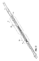
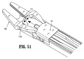
ここで図1〜図5を参照すると、本開示の実施形態による外科手術用クリップアプライアが、一般に100として示されている。クリップアプライア100は、ハンドルアセンブリ102、およびハンドルアセンブリ102から遠位に延びるシャフトアセンブリ104を備える内視鏡部分を備える。
With reference now to FIGS. 1-5, a surgical clip applier according to an embodiment of the present disclosure is shown generally as 100. The
シャフトアセンブリ104は、約10mmの外径を有する。シャフトアセンブリ104は、意図される用途(例えば、肥満学的外科手術)に依存して、より長いかまたはより短い種々の長さを有し得る。
The
図1〜図5に見られるように、外科手術用クリップアプライア100は、1対の顎106を備え、これらの顎は、シャフトアセンブリ104の遠位端に設置され、そしてハンドルアセンブリ102のトリガ108により起動可能である。顎106は、適切な生体適合性材料(例えば、ステンレス鋼またはチタン)から形成され、そして内部に外科手術用クリップ「C」を受容するためのチャネル106aを、顎の間に規定する。顎106が互いに対して開いた状態または近接していない状態にある場合に、顎106の幅は、シャフトアセンブリ104の外径より大きい。
As seen in FIGS. 1-5, the
顎106は、シャフトアセンブリ104に対して長手軸方向に静止するように、シャフトアセンブリ104の遠位端に設置される。ノブ110が、ハンドルアセンブリ102の遠位端に回転可能に設置され得、そしてシャフトアセンブリ104に固定され得、シャフトアセンブリ104および顎106を長手方向軸の周りでの360°の回転を伝達および/または提供する(図2を参照のこと)。
The
ここで図1〜図8を参照すると、外科手術用クリップアプライア100のハンドルアセンブリ102が示されている。ハンドルアセンブリ102は、ハウジング103を備え、このハウジングは、第一または右側の半セクション103a、および第二または左側の半セクション103bを有する。ハンドルアセンブリ102は、右側半セクション103aと左側半セクション103bとの間に旋回可能に支持された、トリガ108を備える。ハンドルアセンブリ102は、ハウジング103に形成された窓103cを規定し、この窓は、以下でより詳細に議論されるように、計数機構を支持および表示するためのものである。ハンドルアセンブリ102のハウジング103は、適切なプラスチック材料から形成され得る。
Referring now to FIGS. 1-8, the
ハウジング103は、右側半セクション103aと左側半セクション103bとの間に、駆動アセンブリ120を支持する。駆動アセンブリ120は、ウィッシュボーンリンク122を備え、このウィッシュボーンリンクは、トリガ108に旋回可能に接続された第一の端部、およびクランクプレート124に旋回可能に接続された第二の端部を有する。図6〜図9に見られるように、駆動アセンブリ120は、クランクプレート124に回転可能に接続された駆動コネクタ134、駆動コネクタ134に相互接続されたプランジャー135、および駆動コネクタ134に支持されたばね136を備える。プランジャー135は、内部に駆動棒140の近位端を受容するように構成および適合された、長手軸方向スロット135aを規定する。
The
駆動棒140は、一体ピン135bを介してプランジャー135に接続される(図9を参照のこと)。キャップ144が提供され、このキャップを通ってプランジャー135が延びる。シール(図示せず)が提供されて、プランジャー135と外側管150との間に気密シールを作製する。
The
図6〜図8に見られるように、ハンドルアセンブリ102は、ラック124aをさらに備える。ラック124aは、ラック124aがクランクプレート124と一緒に移動可能であるように、クランクプレート124の内部/表面に形成される。ラック124aは、複数の歯を備え、これらの歯は、クランクプレート124に規定された遠位凹部124bと近位凹部124cとの間に介在する。凹部124bおよび124cは、クランクプレート124が近位への移動と遠位への移動との間を変更する場合に、つめ224が反転してラック124aの歯を越えて戻ることを可能にするために提供される。
As seen in FIGS. 6-8, the
ハンドルアセンブリ102は、つめ224がクランクプレート124のラック124aと実質的に作動可能な係合を行う位置で、つめピン226によってハウジング130に旋回可能に接続されたつめ224をさらに備える。つめ224は、つめ歯224aを備え、このつめ歯は、クランクプレート124のラック124aの歯と選択的に係合可能である。つめ歯224aは、ラック歯と係合して、ラック124a、および次にクランクプレート124の、ハンドルアセンブリ102内での長手軸方向の移動を制限する。つめばね228は、つめ224をクランクプレート124のラック124aと作動可能に係合させるように付勢するために、提供される。
Handle assembly 102 further includes a
図6〜図8に見られるように、クランクプレート124は、ピン123を介してウィッシュボーンリンク122に旋回可能に接続される。クランクプレート124は、つめ224と選択的に係合するための、一連のラチェット歯124aを規定する。
As seen in FIGS. 6 to 8, the
図8、図8Aおよび図8Bに見られるように、ハンドルアセンブリは、可聴/触覚フィードバック部材126をさらに備え、この可聴/触覚フィードバック部材は、トリガ108が起動される際に、トリガ108と一緒に共通の軸の周りで回転するように、トリガ108と作動可能に関連する。フィードバック部材126は、複数のラチェットまたは段126bを規定するレース(race)126aを規定する。屈曲可能なアーム127が提供され、この屈曲可能なアームは、フィードバック部材126のレース126aに作動可能に接続または配置されて段126bに接触する第一の端部、およびハウジング103に接続される第二の端部を備える。作動において、トリガ108が起動されると、アーム127は、フィードバック部材126内に形成されたレース126aを通り、そして/またはレース126aに沿って進む。以下でより詳細に議論されるように、アーム127がフィードバック部材126の段126bを越えて移動する際に、アーム127は段126bにスナップし、そして可聴音/クリック音および/または触知可能な振動を生じる。
As seen in FIGS. 8, 8A and 8B, the handle assembly further comprises an audible /
可聴/触覚フィードバック部材126は、クリップが外科手術用クリップアプライア100の顎内に完全に装填した後、装填されたクリップが外科手術用クリップアプライア100の顎により形成された後、および外科手術用クリップアプライア100がホーム位置にリセットされて別のクリップを発射/形成する準備ができた後に、可聴/触知可能指標を生じるために充分な段126bを備える。
The audible /
図6、図7、図8、および図8Aに見られるように、外科手術用クリップアプライア100のハンドルアセンブリ102は、計数機構132をさらに備え、この計数機構は、ハウジング103内に支持されており、そしてハウジング103に規定された窓103cを介して見える。計数機構132は、ディスプレイ132a、プロセッサ132b、およびバッテリなどの形態のエネルギー源(図示せず)を備える。
As seen in FIGS. 6, 7, 8, and 8A, the
ディスプレイ132aは、事象の指標を提供する、当該分野において公知の任意のデバイスであり得る。この事象は、クリップアプライア100の手順または作動に関連し得る。ディスプレイ132aは、液晶ディスプレイ(LCD)である。
ディスプレイ132aは、クリップアプライア100の1つ以上の作動パラメータを外科医に表示する。ディスプレイ132aにより表示される作動パラメータとしては、残っているクリップの量または数、使用されたクリップの数、位置パラメータ、外科手術使用時間、あるいは他の任意の手順のパラメータが挙げられる。
マイラーまたは他のポリマー絶縁材料が、バッテリまたはエネルギー源とプロセッサ132bの接点との間に配置され、この材料は、このバッテリまたはエネルギー源が、保管中に消耗することを防止する。タブが、このタブの容易な除去を可能にする目的で、外科手術用クリップアプライア100のハウジング103から延びる。一旦、このタブが除去されると、バッテリまたは他のエネルギー源がプロセッサ132bの接点と電気的に接触し、次に、ディスプレイ132aにエネルギーを供給する。
Mylar or other polymer insulating material is placed between the battery or energy source and the contacts of the
図6、図7、図8および図8Aに見られるように、外科手術用クリップアプライア100のハンドルアセンブリ102は、計数器起動機構をさらに備え、この計数器起動機構は、第一のアーム130aを有する計数器起動レバー130を備え、この第一のアームは、計数器機構132のプロセッサ132bと作動可能に選択的に係合するように構成および適合される。計数器起動レバー130は、第二のアーム130bをさらに備え、この第二のアームは、ハウジング103内にスライド可能に支持されたアクチュエータプレート128に形成されたスロット128aと作動可能にスライド可能に係合するように構成および適合される。
As seen in FIGS. 6, 7, 8, and 8A, the
作動において、以下により詳細に記載されるように、トリガ108が握られると、トリガ108は、ウィッシュボーンリンク122を遠位に前進させ、クランクプレート124を遠位に前進させる。クランクプレート124のアーム124dが所定の距離だけ前進すると、アーム124dは、アクチュエータプレート128のフィンガー128bと係合または接触する。クランクプレート124がさらに遠位に前進すると、クランクプレート124は、アクチュエータプレート128に遠位方向に力を加えるかまたは引き、これによって、計数器駆動レバー130を起動させて、計数器機構132を起動させる。
In operation, as described in more detail below, when the
具体的には、アクチュエータプレート128が充分な距離だけ遠位に移動すると、計数器起動レバー130の第二のアーム130bがそのスロット128a内でカム作用し、そして計数器起動レバー130を回転させ、その結果、計数器起動レバー130の第一のアーム130aが計数器機構132と係合し、これによって、そのディスプレイに変化を起こす。アクチュエータプレート128が充分な距離だけ近位に移動すると、計数器起動レバー130の第二のアーム130bがホーム位置に戻り、その結果、計数器起動レバー130の第一のアーム130aが、計数器機構132から脱係合する。
Specifically, when the
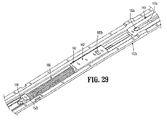
図9〜図31Aを参照すると、外科手術用クリップアプライア100のシャフトアセンブリ104が示され、そして本明細書中以下に記載される。シャフトアセンブリ104およびその構成要素は、適切な生体適合性材料(例えば、ステンレス鋼、チタン、プラスチックなど)から形成され得る。シャフトアセンブリ104は、外側管150を備え、この外側管は、ハウジング103内に支持された近位端150a、遠位端150b、およびこの外側管を通って延びる管腔150cを有する。外側管150は、その外側表面から突出するフランジによって、ハウジング103内に固定される。シャフトアセンブリ104は、上ハウジング152aおよび下ハウジング152bをさらに備え、各々が、外側管150の管腔150c内に配置される。後方上ハウジング154は、外側管150の内部でありかつ上ハウジング152aの近位に配置される。
With reference to FIGS. 9-31A, a
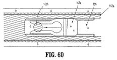
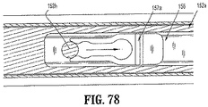
図9、図12および図13に見られるように、シャフトアセンブリ104は、上ハウジング152aと後方上ハウジング154との内部にスライド可能に支持された押し棒156をさらに備える。押し棒156は、狭いプロフィールのプッシャー156cを規定する遠位端156aを備え、このプッシャーは、クリップのスタック「C」のうちの最も遠位にあるクリップ「C1」と選択的に係合/移動(すなわち、遠位に前進)するように、そして最も遠位のクリップ「C1」の最初の形成中にこの最も遠位のクリップ「C1」と接触したままになるように、構成および適合されている。押し棒156は、近位端156bをさらに備える。押し棒156は、キャッチ156eを有する遠位窓156d、遠位窓156dの近位に位置してその各側縁部に形成された1対の凹部156f、側部凹部156fの近位に位置する細長スロット156g、およびスロット156gの近位に位置する最も近位の窓156hを規定する。
As seen in FIGS. 9, 12 and 13, the
図9および図14に見られるように、押し棒156は、その上表面に沿って、押し棒156の側部凹部156fの遠位の位置で、第一のスナップクリップ157aを支持する。第一のスナップクリップ157aは、その枝が押し棒156の上表面からある量で突出するか、または間隔を空けるような様式で、構成される。
As seen in FIGS. 9 and 14, the
図9および図15に見られるように、押し棒156は、その下表面に沿って、押し棒156の最も近位の窓156hの近位の位置で、第二のスナップクリップ157bを支持する。第二のスナップクリップ157bは、その枝が、押し棒156の最も近位の窓156hの上に重なるために充分な量で突出するような様式で、配向される。第二のスナップクリップ157bの枝は、押し棒156の最も近位の窓156hの幅より小さい量だけ、互いから間隔を空けている。
As seen in FIGS. 9 and 15,
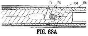
図9および図16〜図20に見られるように、シャフトアセンブリ104は、押し棒156の下に往復可能に支持された前進プレート162をさらに備える。図16および図17に見られるように、第四のスナップクリップ157dが、前進プレート162の近位端に支持される。スナップクリップ157dは、1対の枝を備え、これらの枝は、上ハウジング152aに形成された近位保持溝152mおよび遠位保持溝152n内に取り外し可能に接続される。この様式で、スナップクリップ157dは、近位保持溝152mおよび遠位保持溝152nと取り外し可能に係合して、前進プレート162を近位位置または遠位位置に維持する。前進プレート162の遠位への前進の際に、スナップクリップ157dの枝は、内向きにカム作用し、そして前進プレート162がより遠位に移動し続けることを可能にする。
As seen in FIGS. 9 and 16-20, the
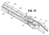
図18〜図20に見られるように、前進プレート162は、内部に形成されてその長さに沿って延びる、一連の窓162aを備える。図19に見られるように、各窓162aは、前進プレート162の表面の下に延びる近位縁部を規定し、これによって、リップまたはレッジ162cを規定する。前進プレート162は、その側縁部から上ハウジング152aに向かう方向に延びる1対の側部フィン162bをさらに備える。図15に見られるように、1対の側部フィン162bは、押し棒156の側部凹部156f内にスライド可能に配置される。
As seen in FIGS. 18-20, the
図9および図21〜図22に見られるように、シャフトアセンブリ104は、上ハウジング152aの内部でありかつ前進プレート162の下に配置された、クリップキャリア164をさらに備える。クリップキャリア164は、ほぼ箱様の構造であり、そして上壁、1対の側壁および下壁を有し、このクリップキャリアを通るチャネルを規定する。クリップキャリア164は、その下壁に形成されてその長さに沿って長手軸方向に延びる、間隔を空けた複数の窓164aを備える(図9を参照のこと)。クリップキャリア164は、その上壁に形成され、そしてその長さに沿って長手軸方向に延びる、細長窓を備える。
As seen in FIGS. 9 and 21-22, the
図9および図21に見られるように、外科手術用クリップのスタック「C」は、クリップキャリア164のチャネル内に、このチャネル内かつ/またはこのチャネルに沿ってスライドするような様式で、装填および/または保持される。クリップキャリア164のチャネルは、複数の外科手術用クリップ「C」を、内部で進行方向に並んだ様式でスライド可能に保持するような構成および寸法にされる。
As seen in FIGS. 9 and 21, the stack of surgical clips “C” is loaded and loaded into the channel of the
図19に見られるように、クリップキャリア164の遠位端は、間隔を空けた1対の弾性中子164bを備える。中子164bは、クリップキャリア164内に保持された外科手術用クリップのスタック「C」のうちの、最も遠位の外科手術用クリップ「C1」のバックスパンと取り外し可能に係合するように構成および適合される。
As seen in FIG. 19, the distal end of
図9および図21〜図24に見られるように、クリップアプライア100のシャフトアセンブリ104は、クリップキャリア164のチャネル内にスライド可能に配置されたクリップ従動子166をさらに備える。以下により詳細に記載されるように、クリップ従動子166は、外科手術用クリップのスタック「C」の後ろに位置し、そしてクリップアプライア100の起動中に、クリップのスタック「C」を前方に推進するために提供される。以下により詳細に記載されるように、クリップ従動子166は、前進プレート162の前方および後方への往復運動によって起動される。
As seen in FIGS. 9 and 21-24, the
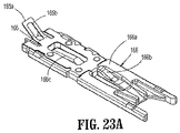
図23、図23Aおよび図24に見られるように、クリップ従動子166は、本体部分166a、本体部分166aから実質的に上向きかつ後方に延びる遠位タブ166b、および本体部分166aから実質的に下向きかつ後方に延びる近位タブ166cを備える。
As seen in FIGS. 23, 23A and 24, the
クリップ従動子166の遠位タブ166bは、前進プレート162の窓162aのレッジ162cに選択的に係合するような構成および寸法にされる。使用において、クリップ従動子166の遠位タブ166bの、前進プレート162の窓162aのレッジ162cへの係合は、前進プレート162が遠位方向に前進または移動する際に、前進プレート162にクリップ従動子166を遠位に漸増的に前進させるかまたは動かす。
The distal tab 166b of the
近位タブ166cは、クリップキャリア164に形成された窓164aと選択的に係合するような構成および寸法にされる。使用において、クリップ従動子166の近位タブ166cの、クリップキャリア164に形成された窓164a内への係合は、クリップ従動子166が近位方向に動くことまたは移動することを防止する。
クリップ従動子166は、ロックアウトプレート165を備え、このロックアウトプレートは、このクリップ従動子に支持されるか、あるいはこのクリップ従動子と一体的に形成される。ロックアウトプレート165は、そこから延びる窓165dを規定する弾性テイル165aを備え、この弾性テイルは、クリップ従動子166の本体部分166aから上向きかつ後方に向く。
The
図9、図25および図38に見られるように、シャフトアセンブリ104は、駆動チャネル168をさらに備え、この駆動チャネルは、チャネルアセンブリ104内に、クリップキャリア164の下の位置で往復可能に支持される。駆動チャネル168は、実質的にU字型のチャネルであり、そのバックスパン168cから、クリップキャリア164から離れる方向に、下ハウジング152bに向かう方向に延びる間隔を空けた1対の側壁168bを備える。駆動チャネル168は、タブ168dをさらに備え、このタブは、バックスパン168cから、スロット168aの近位の位置で突出し、そして側壁168bの方向に延びる。図41に見られるように、駆動チャネル168は、側壁168bのうちの1つに形成されたスロットまたは窓168eを規定し、このスロットまたは窓は、楔プレート解除機構194の歯194cを選択的に受容するためのものである。
As seen in FIGS. 9, 25 and 38, the
図9および図25に見られるように、クリップアプライア100のシャフトアセンブリ104は、駆動チャネル168に固定された駆動チャネルストラップ167を備える。ストラップ167は、駆動チャネル168の側壁168bを横切って延びるように、この側壁に固定される。ストラップ167は、細長スロット168aの遠位の位置で、駆動チャネル168に固定される。ストラップ167は、楔プレート172が駆動チャネル168のバックスパン168cと顎106との間に延びるように、駆動チャネル168に固定される。
As seen in FIGS. 9 and 25, the
図9、図26および図27に見られるように、クリップアプライア100は、1対の顎106を備え、これらの顎は、シャフトアセンブリ104の遠位端に設置され、そしてトリガ108により起動可能である。顎106は、適切な生体適合性材料(例えば、ステンレス鋼またはチタン)から形成される。
As seen in FIGS. 9, 26 and 27,
顎106は、下ハウジング152bに形成されたボスを介して、駆動チャネル168の遠位端に隣接して設置される。これらのボスは、顎106に形成された受容スロットに係合し、その結果、顎106は、駆動チャネル168に対して静止して保持される。図25に見られるように、顎106は、外科手術用クリップ「C」を内部に受容するためのチャネル106aを、間に規定する。
The
図9、図25および図26に見られるように、クリップアプライア100のシャフトアセンブリ104は、楔プレート172をさらに備え、この楔プレートは、駆動チャネル168と顎106との間に介在する遠位端、およびシャフトアセンブリ104を通って延びる近位端を有する。楔プレート172は、顎106の間に選択的に作動可能に介在するために、実質的にテーパ状の遠位端172aを備える。図26に見られるように、楔プレート172は、その下表面から突出するフィンまたはタブ172bを規定する。図22に見られるように、楔プレート172は、そこに形成された最も近位のスロット172cを規定し、このスロットは、内部にコネクタプレート174の第二のステム174cをスライド可能に受容するためのものである。
As seen in FIGS. 9, 25, and 26, the
図22に見られるように、第三のスナップクリップ157cは、楔プレート172の近位端で支持される。第三のスナップクリップ157cは、その枝が楔プレート172に形成された最も近位の窓172cの上に重なるために充分な量で突出するような様式で、配向される。第三のスナップクリップ175cの枝は、楔プレート172の最も近位の窓172cの幅より小さい量だけ、互いから間隔を明けている。
As seen in FIG. 22, the
図9、図18、図20および図36に見られるように、クリップアプライア100のシャフトアセンブリ104は、コネクタプレート174をさらに備え、このコネクタプレートは、押し棒156と楔プレート172との間にスライド可能に介在し、そして押し棒156と楔プレート172との各々に取り外し可能に接続可能である。コネクタプレート174は、テーパ状の遠位端174a、その上表面から延びる第一のステム174b、およびその底表面から延びる第二のステム174cを備える。各ステム174b、174cは、実質的に涙滴の形状のプロフィールを有し、各ステム174b、174cの遠位端は、その近位端より大きい。
As seen in FIGS. 9, 18, 20, and 36, the
作動において、コネクタプレート174の第一のステム174bは、押し棒156に固定された第二のスナップクリップ157bと取り外し可能に接続するための構成および寸法にされており、そしてコネクタプレート174の第二のステム174cは、楔プレート172に固定された第三のスナップクリップ157cと取り外し可能に接続されるための構成および寸法にされる。
In operation, the
図22、図36および図37に見られるように、コネクタプレート174の第二のステム174cは、駆動棒140に規定された窓140b内に延びる。この様式で、駆動棒140もまた往復する際に、コネクタプレート174がそれと共に往復する。
As seen in FIGS. 22, 36 and 37, the
図31Aに見られるように、ガード198が、下ハウジング152b内に、第三のスナップクリップ157cの最初の遠位への前進中に第三のスナップクリップ157cの枝間の相対距離が維持されるような位置で支持される。この様式で、コネクタプレート174の第二のステム174bは、第三のスナップクリップ157cがガード198を越えるまで、第三のスナップクリップ157cから尚早に脱係合し得ない。
As seen in FIG. 31A, the
図9、図27、図29および図41に見られるように、クリップアプライア100のシャフトアセンブリ104は、下ハウジング152bのチャネル内にスライド可能に支持されたスライダジョイント180をさらに備える。スライダジョイント180は、本体部分182、およびこの本体部分から延びるロッド184を備える。下ハウジング152bのチャネル内で適切に配置されると、スライドジョイント180のロッド184は、実質的に遠位方向に延びる。スライダジョイント180のロッド184は、下ハウジング152bに形成され、そして下ハウジング152bのチャネルから延びるスタブ(stub)152dをスライド可能に通過する(図29を参照のこと)。シャフトアセンブリ104は、圧縮ばねの形態の付勢部材186をさらに備え、この付勢部材は、ロッド184に支持され、そして下ハウジング152bのスタブ152dと、スライダジョイント180の本体部分182との間に介在する。
As seen in FIGS. 9, 27, 29 and 41, the
スライダジョイント180の本体部分182は、その近位端の近くに形成されたボス182aを備え、このボスは、駆動棒140の細長スロット140aとスライド可能に係合するために構成および適合される(図29を参照のこと)。スライドジョイント180の本体部分182は、その遠位端の近くに形成されたポケット182bをさらに備え、このポケットは、内部に駆動チャネル168のタブ168dを受容するために構成および適合される(図38および図39を参照のこと)。
The
図9、図27および図28に見られるように、クリップアプライア100のシャフトアセンブリ104は、下ハウジング152bのチャネルおよび駆動チャネル168内にスライド可能に支持された楔プレートロック190をさらに備える。楔プレートロック190は、本体部分190a、本体部分190aから遠位に延びる棒190b、本体部分190aから近位に延びるテイル190c、本体部分190aの上表面に形成されたポケット190d、およびテイル190cから延びるステムまたは歯190eを備える。シャフトアセンブリ104は、圧縮ばねの形態の付勢部材192をさらに備え、この付勢部材は、棒190bに支持され、そして下ハウジング152bと楔プレートロック190の本体部分190aとの間に介在する。
As seen in FIGS. 9, 27 and 28, the
クリップアプライア100のシャフトアセンブリ104は、下ハウジング152bのチャネル内に回転可能に支持された楔プレート解除機構194をさらに備える。楔プレート解除機構194は、楔プレートロック190のテイル190cから延びる歯190eと係合するために係合されたステム194a、ステム194aから外向きに楔プレートロック190のテイル190cに向かう方向へと延びるハンマー194b、および楔プレートロック190のテイル190cから離れる方向へとステム194aから延びる歯194cを備える。
The
外科手術用クリップを標的組織(例えば、脈管)に形成またはクリンプするための外科手術用クリップアプライア100の作動を、ここで記載する。図32〜図43を参照すると、その作動または使用の前の外科手術用クリップアプライア100が示されている。図32および図33に見られるように、クリップアプライア100の使用または発射の前に、トリガ108は一般に、非圧縮状態または非起動状態にある。従って、駆動アセンブリ120のクランクプレート124は、引き込まれた位置または最も近位の位置にあり、従って、プランジャー135および駆動棒140もまた、引き込まれた位置にある。クランクプレート124が引き込まれた位置にある場合、つめ224は、クランクプレート124に規定された遠位凹部124b内に配置される。
Operation of the
駆動アセンブリ120および駆動棒140が引き込まれた位置にある場合、図35〜図37に見られるように、コネクタプレート174は、引き込まれた位置または最も近位の位置に位置する。コネクタプレート174が引き込まれた位置または最も近位の位置にある状態で、押し棒156もまた、引き込まれた位置または最も近位の位置にあり、そしてコネクタプレート174の第一の涙滴型ステム174bは、押し棒156の最も近位の窓156hの近位端に配置され、そして第二のスナップクリップ157bの枝とスナップばめ係合して維持される。また、コネクタプレート174が引き込まれた位置または最も近位の位置にある状態で、楔プレート172もまた、引き込まれた位置または最も近位の位置にあり、そしてコネクタプレート174の第二の涙滴型ステム174cは、楔プレート172の最も近位の窓172cの近位端に配置され、そして第三のスナップクリップ157cの枝とスナップばめ係合して維持される。
When
図36および図37に見られるように、駆動アセンブリ120および駆動棒140が引き込まれた位置にある場合、スライダジョイント182のタブ182aは、駆動棒140の細長スロット140aの最も遠位の位置に位置する。
As seen in FIGS. 36 and 37, when
図38および図39に見られるように、駆動アセンブリ120および駆動棒140が引き込まれた位置にある場合、クリップ従動子166は、クリップキャリア164のチャネルの最も近位の端部に位置し、クリップ従動子166の遠位タブ166bは、前進プレート162の最も近位の窓162a内に作動可能に配置され、そして近位タブ166cは、クリップキャリア164の最も近位の窓164a内に作動可能に配置される。
As seen in FIGS. 38 and 39, when the
図38および図39の参照を続けて、駆動アセンブリ120および駆動棒140が引き込まれた位置にある場合、スライダジョイント180は、最も近位の位置に位置し、そして駆動チャネル168のタブ168dは、スライダジョイント180のポケット182b内に配置されるので、駆動チャネル168もまた、最も近位の位置に位置する。図38および図39に見られるように、スライダジョイント180は、下ハウジング152bから突出する物理的ストップ152e(図30を参照のこと)に当接する。
With continued reference to FIGS. 38 and 39, when
図40および図41に見られるように、駆動アセンブリ120および駆動棒140が引き込まれた位置にある場合、楔プレートロック190は、最も近位の位置に位置し、その結果、そのテイル190cから延びる歯190eは、下ハウジング152bに形成された傾斜レッジ152fの近位に配置される(図30および図31を参照のこと)。図41に見られるように、楔プレートロック190は、下ハウジング152bから突出する物理的ストップ152gに当接する。図41にまた見られるように、楔プレート解除機構194は、その歯194cが駆動チャネル168の側壁168bに形成された窓168e内に突出するように、第一の位置に配置される。
As seen in FIGS. 40 and 41, when
図42および図43に見られるように、駆動アセンブリ120および駆動棒140が引き込まれた位置にある場合、押し棒156のプッシャー156cは、クリップキャリア164に保持された最も遠位にあるクリップ「C1」のバックスパンの近位に配置される。最も遠位のクリップ「C1」は、クリップキャリアの中子164bによって、クリップキャリア164のチャネル内に保持される。また、この位置において、上記のように、楔プレート172は、最も近位の位置に位置し、その結果、その遠位端172aは、顎106の近位に位置する。
As seen in FIGS. 42 and 43, when the
図43に見られるように、駆動チャネル168が最も近位の位置にある状態で、その遠位端は、顎106の近位カム作用表面106bから脱係合する。
As seen in FIG. 43, with the
ここで図44〜図54を参照すると、トリガ108が初期位置から握られるかまたは起動される場合、最初の行程の第一段階中に、トリガ108は、ウィッシュボーンリンク122に、クランクプレート124を遠位方向に移動させ、これは次に、駆動コネクタ134およびプランジャー135を遠位に移動させ、そして駆動棒140を遠位に移動させる。プランジャー135が遠位に移動するにつれて、ばね136が最初の量だけ圧縮される。
Referring now to FIGS. 44-54, when the
それと同時に、クランクプレート124が遠位に移動するにつれて、つめ224がクランクプレート124の遠位凹部124aから移動または回転すると、ラック124aの歯がつめ224の歯224aと係合する。この様式で、クランクプレート124は、完全な遠位への行程を完了させずには、最も近位の位置に戻り得ない。
At the same time, as the
図44に見られるように、トリガ108が最初の量だけ握られると、アーム127が、フィードバック部材126のレース126aを通って並進を開始する。
As seen in FIG. 44, when the
図46に見られるように、駆動棒140が遠位方向に移動するにつれて、駆動棒140はコネクタプレート174を遠位方向に押す。押し棒156は、第二のスナップクリップ157bを介してコネクタプレート174に選択的に接続されるので、押し棒156は、遠位方向に前進するかまたは引かれる。また、楔プレート172は第三のスナップクリップ157cを介してコネクタプレート174に選択的に接続されるので、楔プレート172もまた、遠位方向に前進するかまたは引っ張られる。
As seen in FIG. 46, as
駆動棒140が遠位方向に移動するにつれて、その細長スロット140aもまた遠位方向に移動し、その結果、スライダジョイント182のタブ182aは、この細長スロットに対して近位方向に並進する。
As
図47〜図49に見られるように、楔プレート172が遠位方向に移動するにつれて、楔プレート172のタブ172bが楔プレートロック190のポケット190d内に保持されているので、楔プレートロック190は、遠位方向に移動するかまたは引っ張られ、そのテイル190cの歯190eに、下ハウジング152bに形成された傾斜レッジ152fにカム作用させ、これによって、傾斜レッジ152fの近位の位置から、傾斜レッジ152fの遠位の位置まで移動する。楔プレートロック190が遠位方向に移動するにつれて、付勢部材192が最初の量だけ圧縮される。図49に見られるように、楔プレートロック190は、楔プレートロック190が下ハウジング152bに形成された物理的ストップと当接するまで、遠位方向に移動する。
As seen in FIGS. 47-49, as the
図47Aに見られるように、押し棒156が遠位方向に移動するにつれて、前進プレート162のフィン162bが、押し棒156の側部凹部156fの近位端と接触または係合するまで、押し棒156の側部凹部156f内で所定の距離だけ並進する。
As seen in FIG. 47A, as the
図47Bおよび図47Cに見られるように、楔プレート172が遠位方向に移動するにつれて、コネクタプレート174の第二のステム174cと第三のスナップクリップ157cとの接続に起因して、コネクタプレート174の第二のステム174cは、ガード198によって、第三のスナップクリップ157cから尚早に接続を外されることを防止される。具体的には、ガード198は、第三のスナップクリップ157cの枝の尖端に作用して、コネクタプレート174が遠位方向に移動する際に第二のステム174cによって発生される遠位への力によりこれらの枝に作用する力に起因して、これらの枝が外向きに広がることを防止する。
As seen in FIGS. 47B and 47C, as the
図50に見られるように、押し棒156が遠位方向に移動するにつれて、そのプッシャー156cが最も遠位のクリップ「C1」のバックスパンと係合し、そして最も遠位のクリップ「C1」を遠位方向に推進し始める。押し棒156が最も遠位のクリップ「C1」を遠位方向に移動させるにつれて、最も遠位のクリップ「C1」は、クリップキャリア164の中子164bの後ろからスナップを外し、そして顎106のチャネル106a内に入り始める。
As seen in FIG. 50, as
図51に見られるように、楔プレート172が遠位方向に移動するにつれて、その遠位端172aは、顎106の間に入り、顎106を外向きに広げる。
As seen in FIG. 51, as the
楔プレート172は、図52〜図54に見られるように、一旦、楔プレートロック190が下ハウジング152bに形成された物理的ストップに当接すると、遠位方向へのさらなる移動を防止される。しかし、駆動棒140は、コネクタプレート174を遠位方向に移動させ続ける。コネクタプレート174は、遠位に力を加えられ続けるので、一旦、第三のスナップクリップ157cの枝の尖端がガード198を越えて遠位に移動すると、第二のステム174cに作用する力は、第三のスナップクリップ157cの枝を外向きに広げ、そして第二のステム174cをこれらの枝の間からスナップを外すために十分であり、これによって、コネクタプレート174が遠位方向に移動し続けることを可能にする。
As seen in FIGS. 52-54, the
ここで図55〜図69を参照すると、トリガ108が、最初の行程の第一段階から、最初の行程の第二段階を通してさらに握られるかまたは起動されると、トリガ108は、ウィッシュボーンリンク122に、クランクプレート124をさらに遠位方向に移動させ、これは次に、駆動コネクタ134および引き続いてプランジャー135を、さらに遠位に移動させ、そして駆動棒140をさらに遠位に移動させる。プランジャー135が遠位に移動するにつれて、ばね136がさらなる量だけ圧縮される。
Referring now to FIGS. 55-69, when the
それと同時に、クランクプレート124が遠位に移動するにつれて、そのラック124aの歯が、つめ224の歯224aに対してさらに遠位に移動する。従って、クランクプレート124は依然として、完全な遠位への行程を完了させずには、最も近位の位置に戻りえない。
At the same time, as the
図55に見られるように、クランクプレート124が遠位に移動するにつれて、所定の距離の後に、そのアーム124dがアクチュエータプレート128のフィンガー128bと係合または接触する。クランクプレート124がさらに遠位に前進すると、クランクプレート124は、アクチュエータプレート128に遠位方向に力を加えるかまたは引き、これによって、計数器起動レバー130を起動させて、計数器機構132を起動させる。
As seen in FIG. 55, as the
具体的には、アクチュエータプレート128が遠位に充分な距離だけ移動すると、計数器起動レバー130の第二のアーム130bがそのスロット128a内でカム作用して回転するように推進され、その結果、計数器起動レバー130の第一のアーム130aが計数器機構132と係合し、これによって、そのディスプレイに変化を起こす。具体的には、このディスプレイは、外科手術用クリップアプライア100内に残っているクリップの数を表示し、1ずつ減少する。あるいは、クリップ計数器機構は、1ずつ増加するか、または他の何らかの変化を生じる。
Specifically, when the
トリガ108がさらに握られると、アーム127は、フィードバック部材126のレース126aを通って並進し続ける。トリガ108を握っている最中のこの時点で、外科手術用クリップが顎106内に装填される。従って、アーム127は、フィードバック部材126のレース126aに形成された段126bと相互作用し、そして可聴/触知可能指標を生じて、使用者に、クリップが顎内に装填されたことを伝える。
As the
図57に見られるように、駆動棒140がさらに遠位方向に移動するにつれて、駆動棒140は、コネクタプレート174を遠位方向に押し続ける。押し棒156は、第二のスナップクリップ157bを介してコネクタプレート174に選択的に接続されたままであるので、押し棒156は、遠位方向にさらに前進するかまたは引っ張られる。しかし、楔プレート172の第三のスナップクリップ157cがコネクタプレート174の第二のステム174cから接続を外されているので、楔プレート172は、遠位方向にさらには前進も引っ張られもしない。
As seen in FIG. 57, as
図56A〜図56Cに見られるように、押し棒156が遠位方向に移動し続けるにつれて、前進プレート162の1対のフィン162bが押し棒156の側部凹部156fの近位端によって係合された状態で、押し棒156は、前進プレート162を遠位方向に前進させるかまたは引っ張る。
As seen in FIGS. 56A-56C, as the
図56Bおよび図56Cに見られるように、前進プレート162が遠位に前進するにつれて、スナップクリップ157dが近位保持溝157mから脱係合し、そして上ハウジング152aに形成された遠位保持溝157nと係合する。
As seen in FIGS. 56B and 56C, as the
図57に見られるように、駆動棒140は、スライダジョイント182のタブ182aが駆動棒140の細長スロット140aの最も近位の位置まで相対的に並進するまで、遠位方向に移動する。
As seen in FIG. 57, the
押し棒156が遠位方向に移動し続けるにつれて、押し棒156は、フィン162bを介して、前進プレート162を遠位方向に推進し続ける。図58に見られるように、前進プレート162が遠位方向に移動するにつれて、クリップ従動子166の遠位タブ166bが、クリップ従動子166をクリップキャリア164に対して遠位方向に推進するために、クリップ従動子166の遠位タブ166bを受容する窓162aの近位縁部により係合され、これによって、クリップのスタック「C」を漸増する量だけ前進させる。クリップ従動子166が遠位方向に移動するにつれて、その近位タブ166cは、クリップキャリア164の相対的に近位の窓164aから、クリップキャリア164の相対的に遠位の窓164aまで、窓164aの1つ分だけ遠位に移動させられる。
As
図58〜図60に見られるように、押し棒156が遠位方向に移動するにつれて、押し棒156に支持される第一のスナップクリップ157aが、上ハウジング152aのボス152hにスナップし、これによって、押し棒156を前方位置に維持する。
As seen in FIGS. 58-60, as the
さらに、図61に見られるように、押し棒156が遠位方向に移動し続けるにつれて、クリップのスタック「C」が遠位方向に移動させられる。
Further, as seen in FIG. 61, as the
図62に見られるように、押し棒156が遠位方向に移動するにつれて、そのプッシャー156cは、最も遠位のクリップ「C1」が顎106のチャネル106a内に完全に入るまで、最も遠位のクリップ「C1」を遠位方向に移動させ続ける。作動において、押し棒156のプッシャー156cは、装填されたクリップ「C」に安定性を提供し、そしてこのクリップの適切な位置を維持する目的で、クリップ「C」の形成中、クリップ「C」のバックスパンと接触したままである。
As seen in FIG. 62, as
図63に見られるように、駆動棒140が遠位方向にさらに移動するにつれて、その肩部140cは、駆動チャネル168の最も近位の端部に接触する。この様式で、駆動棒140が遠位方向にさらに移動するにつれて、駆動棒140は、駆動チャネル168を遠位方向に移動または推進する。
As seen in FIG. 63, as
図64に見られるように、駆動チャネル168が遠位方向に移動するにつれて、駆動チャネル168の側壁168bに形成された窓168eの近位縁部が楔プレート194の歯194cに接触し、楔プレート解除機構194を回転させる。楔プレート解除機構194が回転するにつれて、そのハンマー194bが楔プレートロック190の歯190eを押し付け、歯190eを後ろの傾斜レッジ152fから外すように推進するかまたは追い出す。このようにする間に、図65に見られるように、付勢部材192が圧縮を解除され、これによって、楔プレートロック190を近位方向に移動させる。図66に見られるように、楔プレートロック190が近位方向に移動するにつれて、楔プレート172がこの楔プレートロック190に接続されているので、楔プレート172は、近位方向に移動して、その遠位端172aを顎106との係合から引き抜く。
As seen in FIG. 64, as
図58および図67〜図69に見られるように、押し棒156は、ボス152hと第一のスナップクリップ157aとの接続により遠位位置に維持されているので、駆動棒140がさらに遠位方向に移動するにつれて、コネクタプレート174に作用する力は、第二のスナップクリップ157bをコネクタプレート174の第一のステム174bから脱係合させ、これによって、コネクタプレート174が遠位方向に移動し続けることを可能にする。
As seen in FIGS. 58 and 67-69, the
図67A〜図69Aに見られるように、ある実施形態において、第二のスナップクリップ157bの枝の先端は、外向きに突出するように構成され得、これによって、後方上ハウジング154(図9を参照のこと)の表面と係合し、これによって、第二のスナップクリップ157bがコネクタプレート174の第一のステム174bから尚早に脱係合することを防止する。この実施形態において、凹部が、後方上ハウジング154の表面に形成され得、その位置は、第二のスナップクリップ157bの枝が外向きに広がり得る位置と一致し、従って、コネクタプレート174の第一のステム174bが脱係合して遠位方向に移動し続けることを可能にする。
As seen in FIGS. 67A-69A, in one embodiment, the tip of the branch of the
図70〜図75に見られるように、トリガ108が最初の行程の最終段階を介して起動されるにつれて、トリガ108は、ウィッシュボーンリンク122に、クランクプレート124を遠位方向にさらに移動させ、これは次に、駆動コネクタ134およびプランジャー135をさらに遠位に移動させ、そして駆動棒140を遠位にさらに移動させる。駆動コネクタ134が遠位に移動するにつれて、ばね136がさらなる量だけ圧縮される。
As seen in FIGS. 70-75, as the
それと同時に、クランクプレート124が遠位に移動するにつれて、そのラック124aの歯が、つめ224の歯224aに対してさらに遠位に移動して、つめ224の歯224aがクランクプレート124の近位凹部124cに入る際に、ラック124aの歯がつめ224の歯224aと脱係合し、従ってリセットされる位置にくる。従って、クランクプレート124は、トリガ108の解放の際に、最も近位の位置まで戻り得る。
At the same time, as the
図72〜図74に見られるように、トリガ108の最初の行程の最終段階の間に、駆動チャネル168およびストラップ167は、顎106に対して遠位方向に移動し、その結果、駆動チャネル168の遠位縁部が顎106のカム作用表面106bに係合し、顎106を閉じさせ、そしてこれらの顎の間に位置するクリップ「C1」を形成する。図74に見られるように、押し棒156のプッシャー156cは遠位位置に残っており、クリップ「C」の形成中、このクリップ「C」のバックスパンと接触している。
As seen in FIGS. 72-74, during the final phase of the first stroke of
図55に見られるように、トリガ108が最後の量だけ握られると、アーム127は、フィードバック部材126のレース126aを通って並進し続ける。トリガ108を握っている間のこの時点において、外科手術用クリップ「C1」は、顎106によって完全に形成される。従って、アーム127は、フィードバック部材126のレース126aに形成された別の段126bと相互作用し、そして可聴/触知可能指標を生じ、使用者に、外科手術用クリップ「C1」が顎106によって形成されたことを伝える。
As seen in FIG. 55, when the
図75に見られるように、外科手術用クリップ「C1」は、脈管「V」または他の任意の生物学的組織上に形成またはクリンプされ得る。 As seen in FIG. 75, surgical clip “C1” may be formed or crimped on vessel “V” or any other biological tissue.
ここで図76〜図84を参照すると、トリガ108が握られていない位置または非作動位置まで戻される場合のクリップアプライア100の作動が示される。図76に見られるように、トリガが握られていない位置まで戻るにつれて、ばねが非圧縮状態にされ、これによって、クランクプレート124を近位方向に移動させ、これは次に、プランジャーを近位に移動させ、そして駆動棒を近位に移動させる。つめ224がリセットされているので、ここでクランクプレート124は、つめ224の歯224aがクランクプレート124の遠位凹部に再度入るまで、近位に移動される。
Referring now to FIGS. 76-84, the operation of the
図76Aに見られるように、クランクプレート124が近位に移動するにつれて、そのアーム124dがアクチュエータプレート128のフィンガー128bと脱係合し、アクチュエータプレート128が近位方向に移動することを可能にする。アクチュエータプレート128が近位に移動するにつれて、計数器起動レバー130の第二のアーム130bがそのスロット128b内でカム作用し、そして回転するように推進され、その結果、計数器起動レバー130の第一のアーム130aが計数器機構132から脱係合する。
As seen in FIG. 76A, as the
図77に見られるように、駆動棒140が近位方向に移動するにつれて、駆動棒140は、第一のステム174bを介してコネクタプレート174を引く。コネクタプレート174が近位方向に移動するにつれて、第一のステム174bが第二のスナップクリップ157bの枝に係合し、そして第二のスナップクリップ157bを介して押し棒156を近位方向に推進する。
As seen in FIG. 77, as
図78に見られるように、押し棒156に作用する力が押し棒156を近位方向に移動させるにつれて、この力が、上ハウジング152aのボス152hと一緒になった第一のスナップクリップ157aの保持力を上回り、これによって、第一のスナップクリップ157aをボス152hから解放し、そして押し棒156が近位方向に移動することを可能にする。
As seen in FIG. 78, as the force acting on
図79に見られるように、押し棒156が近位方向に移動し続けるにつれて、その側部凹部156fの遠位端が前進プレート162のフィン162bと係合し、そして前進プレート162を近位方向に移動させる。押し棒156が近位方向に移動するにつれて、押し棒のノーズ156cが、残りのクリップのスタック「C」の最も遠位のクリップの後ろにスナップし、これによって、新たな最も遠位のクリップ「C1」になる。
As seen in FIG. 79, as
図80に見られるように、前進プレート162が近位方向に移動するにつれて、クリップキャリア164内でのクリップ従動子166の相対位置を保持する目的で、クリップ従動子166の近位タブ166cがクリップキャリア164の窓164aの近位縁部と係合する。前進プレート162が近位方向に移動するにつれて、その遠位タブ166bが、前進プレート162の相対的に近位の窓162aから、前進プレート162の相対的に遠位の窓162aへと、窓162aの1つ分だけ遠位に前進する。
As seen in FIG. 80, the
図81に見られるように、押し棒156がその近位への移動を止め、上ハウジング半体152aの内側表面から突出するボスと係合すると、コネクタプレート174の連続的な近位への移動は、第一のステム174bを第二のスナップクリップ157bと再度係合させる。押し棒156の近位への移動が停止した状態で、コネクタプレート174の連続的な近位への移動は、第一のステム174bを第二のスナップクリップ157bと再度係合させる。
As seen in FIG. 81, when the
図82および図83に見られるように、コネクタプレート174が近位方向に移動するにつれて、駆動棒140の近位への移動の結果として、第二のステム174cが第三のスナップクリップ157cの枝と係合し、そして第三のスナップクリップ157cを介して、楔プレート172を近位方向に推進する。楔プレート172が近位方向に移動するにつれて、楔プレートロック190は、楔プレートロック190が下ハウジング半体152bの物理的ストップと接触し、これによって楔プレート172の近位への移動を止めるまで、近位方向に移動する。一旦、第三のスナップクリップ157cの枝の先端がガード198を近位に越えて移動し、楔プレート172がその近位への移動を止めると、コネクタプレート174の連続的な近位への移動は、第二のステム174cを第三のスナップクリップ157cと再度係合させる。
As seen in FIGS. 82 and 83, as the
トリガ108が非起動位置に戻されると、アーム127は、フィードバック部材126のレース126aを通って並進し、そしてフィードバック部材126のレース126aに形成された別の段126bと相互作用し、そして可聴/触知可能指標を生じ、使用者に、外科手術用クリップアプライア100がリセットされ、そして再度発射する準備ができたことを伝える。
When the
ここで図84〜図85を参照すると、最後の外科手術用クリップ「C」の適用後の、外科手術用クリップアプライア100の構成が示されている。図84および図85に見られるように、最後の外科手術用クリップが前進および形成されると、押し棒156が依然として前進位置または遠位位置にある状態で、クリップ従動子166は、そのロックアウトプレート165が前進プレート162の窓162aを通して上向きに付勢されて押し棒156の遠位窓156dに入るために充分な量で、割送りプレート158によって漸増的に前進させられている。押し棒156の遠位窓156d内でのロックアウトプレート165の位置決めは、そのキャッチ156eがロックアウトプレート165の窓165bに入って係合することを可能にする。この様式で、クリップ従動子166は、その近位タブ166cがクリップキャリア164の遠位窓164aと係合することによって遠位位置に維持されるので、ロックアウトプレート165は、押し棒156のキャッチ156eと係合し、そして押し棒156が最も近位の位置に戻ってつめ224をリセットすることを防止する。
Referring now to FIGS. 84-85, the configuration of the
押し棒156は、その最も近位の位置に移動し得ないか、または移動することを防止されるので、図86に見られるように、つめ224は、クランクプレート124のラック124aと係合したままであり、そして近位凹部124cに入ることを許容されず、従って、リセットされない。つめ224はリセットされ得ないので、クランクプレート124は、遠位または近位への移動をロックまたは停止される。
As seen in FIG. 86, the
上記記載は、本開示の本の例示であることが理解されるべきである。種々の変更および改変が、本開示から逸脱することなく当業者により考案され得る。従って、本開示は、このような全ての変更、改変および変形を包含することが意図される。添付の図面を参照しながら記載された実施形態は、本開示の特定の例を実証するためのみに提示される。上記および/または添付の特許請求の範囲に記載されるものと実質的に異ならない他の要素、工程、方法および技術もまた、本開示の範囲内であることが意図される。 It should be understood that the above description is illustrative of the books of the present disclosure. Various changes and modifications can be devised by those skilled in the art without departing from the disclosure. Accordingly, the present disclosure is intended to embrace all such alterations, modifications and variations. The embodiments described with reference to the accompanying drawings are presented only to demonstrate certain examples of the disclosure. Other elements, steps, methods and techniques not substantially different from those described above and / or in the appended claims are also intended to be within the scope of the disclosure.
100 クリップアプライア
102 ハンドルアセンブリ
103 ハウジング
103a、103b 半セクション
103c 窓
104 シャフトアセンブリ
106 顎
106a チャネル
108 トリガ
110 ノブ
120 駆動アセンブリ
122 ウィッシュボーンリンク
124 クランクプレート
134 駆動コネクタ
135 プランジャー
136 ばね
140 駆動棒
100
Claims (1)
Applications Claiming Priority (4)
| Application Number | Priority Date | Filing Date | Title |
|---|---|---|---|
| US9278608P | 2008-08-29 | 2008-08-29 | |
| US61/092,786 | 2008-08-29 | ||
| US12/539,671 | 2009-08-12 | ||
| US12/539,671 US8894665B2 (en) | 2008-08-29 | 2009-08-12 | Endoscopic surgical clip applier |
Related Parent Applications (1)
| Application Number | Title | Priority Date | Filing Date |
|---|---|---|---|
| JP2009198977A Division JP5629069B2 (en) | 2008-08-29 | 2009-08-28 | Endoscopic surgical clip applier |
Publications (1)
| Publication Number | Publication Date |
|---|---|
| JP2014208038A true JP2014208038A (en) | 2014-11-06 |
Family
ID=51902738
Family Applications (1)
| Application Number | Title | Priority Date | Filing Date |
|---|---|---|---|
| JP2014092611A Pending JP2014208038A (en) | 2008-08-29 | 2014-04-28 | Clip applier for endoscope surgical operation |
Country Status (1)
| Country | Link |
|---|---|
| JP (1) | JP2014208038A (en) |
Citations (2)
| Publication number | Priority date | Publication date | Assignee | Title |
|---|---|---|---|---|
| JP2008515550A (en) * | 2004-10-08 | 2008-05-15 | タイコ ヘルスケア グループ エルピー | Endoscopic surgical clip applier |
| JP2010051805A (en) * | 2008-08-29 | 2010-03-11 | Tyco Healthcare Group Lp | Endoscopic surgical clip applier |
-
2014
- 2014-04-28 JP JP2014092611A patent/JP2014208038A/en active Pending
Patent Citations (2)
| Publication number | Priority date | Publication date | Assignee | Title |
|---|---|---|---|---|
| JP2008515550A (en) * | 2004-10-08 | 2008-05-15 | タイコ ヘルスケア グループ エルピー | Endoscopic surgical clip applier |
| JP2010051805A (en) * | 2008-08-29 | 2010-03-11 | Tyco Healthcare Group Lp | Endoscopic surgical clip applier |
Similar Documents
| Publication | Publication Date | Title |
|---|---|---|
| JP5478158B2 (en) | Endoscopic surgical clip applier with lockout | |
| JP5629072B2 (en) | Single stroke endoscopic surgical clip applier | |
| JP5629071B2 (en) | Endoscopic surgical clip applier with wedge plate | |
| JP5345910B2 (en) | Endoscopic surgical clip applier with clip holder | |
| JP2015096202A (en) | Endoscopic surgical clip applier with connector plate | |
| EP2543324B1 (en) | Endoscopic clip applier | |
| JP2014208038A (en) | Clip applier for endoscope surgical operation | |
| AU2014271329A1 (en) | Endoscopic surgical clip applier with clip retention |
Legal Events
| Date | Code | Title | Description |
|---|---|---|---|
| A131 | Notification of reasons for refusal |
Free format text: JAPANESE INTERMEDIATE CODE: A131 Effective date: 20150227 |
|
| A521 | Written amendment |
Free format text: JAPANESE INTERMEDIATE CODE: A523 Effective date: 20150507 |
|
| A131 | Notification of reasons for refusal |
Free format text: JAPANESE INTERMEDIATE CODE: A132 Effective date: 20151028 |
|
| A02 | Decision of refusal |
Free format text: JAPANESE INTERMEDIATE CODE: A02 Effective date: 20160330 |