JP2014200436A - X-ray image diagnostic apparatus - Google Patents
X-ray image diagnostic apparatus Download PDFInfo
- Publication number
- JP2014200436A JP2014200436A JP2013078691A JP2013078691A JP2014200436A JP 2014200436 A JP2014200436 A JP 2014200436A JP 2013078691 A JP2013078691 A JP 2013078691A JP 2013078691 A JP2013078691 A JP 2013078691A JP 2014200436 A JP2014200436 A JP 2014200436A
- Authority
- JP
- Japan
- Prior art keywords
- power
- switching circuit
- ray
- arm
- storage unit
- Prior art date
- Legal status (The legal status is an assumption and is not a legal conclusion. Google has not performed a legal analysis and makes no representation as to the accuracy of the status listed.)
- Pending
Links
- 239000003990 capacitor Substances 0.000 claims abstract description 44
- 238000001514 detection method Methods 0.000 claims abstract description 25
- 238000002059 diagnostic imaging Methods 0.000 claims description 14
- 238000002594 fluoroscopy Methods 0.000 claims description 12
- 238000003745 diagnosis Methods 0.000 claims description 2
- 238000007689 inspection Methods 0.000 abstract description 9
- 238000000034 method Methods 0.000 description 29
- 230000008569 process Effects 0.000 description 28
- 238000006243 chemical reaction Methods 0.000 description 20
- 238000003384 imaging method Methods 0.000 description 18
- 238000010586 diagram Methods 0.000 description 8
- 230000006870 function Effects 0.000 description 8
- 230000007246 mechanism Effects 0.000 description 6
- 239000004065 semiconductor Substances 0.000 description 2
- 230000007704 transition Effects 0.000 description 2
- OAICVXFJPJFONN-UHFFFAOYSA-N Phosphorus Chemical compound [P] OAICVXFJPJFONN-UHFFFAOYSA-N 0.000 description 1
- 230000003028 elevating effect Effects 0.000 description 1
- 230000006872 improvement Effects 0.000 description 1
- 230000001678 irradiating effect Effects 0.000 description 1
- 239000011159 matrix material Substances 0.000 description 1
- 230000004048 modification Effects 0.000 description 1
- 238000012986 modification Methods 0.000 description 1
- NJPPVKZQTLUDBO-UHFFFAOYSA-N novaluron Chemical compound C1=C(Cl)C(OC(F)(F)C(OC(F)(F)F)F)=CC=C1NC(=O)NC(=O)C1=C(F)C=CC=C1F NJPPVKZQTLUDBO-UHFFFAOYSA-N 0.000 description 1
- 238000002601 radiography Methods 0.000 description 1
- 230000009467 reduction Effects 0.000 description 1
- 238000001356 surgical procedure Methods 0.000 description 1
- 230000001960 triggered effect Effects 0.000 description 1
Images


Landscapes
- Apparatus For Radiation Diagnosis (AREA)
Abstract
Description
本発明は、X線画像診断装置に係り、特に、X線源に対する電源供給についての改良技術に関する。 The present invention relates to an X-ray diagnostic imaging apparatus, and more particularly to an improved technique for supplying power to an X-ray source.
特許文献1には、X線源及びX線検出器をC型アームにより対向支持するCアーム台車と、X線画像を表示するモニタを搭載したモニタ台車と、を有するCアームシステムが開示されている。 Patent Document 1 discloses a C-arm system having a C-arm carriage that supports an X-ray source and an X-ray detector by a C-type arm and a monitor carriage equipped with a monitor that displays an X-ray image. Yes.
上記Cアームシステムは、Cアーム台車内に曝射用バッテリを搭載し、このバッテリからX線源に給電してX線を出力しているので、曝射用バッテリに必要量がない場合、充電のためにX線の照射を待たなければならない。一方、Cアームシステムには、100V系商用電源受電システムを採用されることが多い。そのため、曝射用バッテリの充電速度を速めたくても、商用電源の定格電力内でシステムを動作させる必要があり、曝射用バッテリの充電待ちによる検査の滞り(ダウンタイム)が生じ得るという問題があった。 In the C-arm system, an exposure battery is mounted in the C-arm carriage, and the X-ray source is fed from this battery to output X-rays. Therefore, it is necessary to wait for X-ray irradiation. On the other hand, a 100V commercial power supply system is often adopted for the C-arm system. Therefore, even if it is desired to increase the charging speed of the exposure battery, it is necessary to operate the system within the rated power of the commercial power supply, and there may be a delay in the inspection (downtime) due to waiting for the charging of the exposure battery. was there.
そこで、本発明は、外部電力の電源容量という制約下においても、検査がより円滑に行えるX線画像診断装置を提供することを目的とする。 Accordingly, an object of the present invention is to provide an X-ray diagnostic imaging apparatus that can perform inspection more smoothly even under the restriction of the power supply capacity of external power.
本発明に係るX線画像診断装置は、前記X線源と、外部電源から受電して、前記X線源に印加する電力を蓄える第一蓄電部と、前記第一蓄電部に対し、前記外部電源からの給電のON/OFFを切り替える第一スイッチング回路と、前記X線源と異なる負荷回路と、前記外部電源から受電して、前記負荷回路に給電する電力を蓄える第二蓄電部と、前記負荷回路、及び前記第二蓄電部に対し、前記外部電源からの給電のON/OFFを切り替える第二スイッチング回路と、前記第二蓄電部に蓄電された電力の残量を検出する検出部と、前記検出部による検出結果に基づいて、前記第一スイッチング回路及び前記第二スイッチング回路のON/OFFの切替制御を行うフィードバック制御部と、を備え、前記フィードバック制御部は、前記第二蓄電部に蓄電された電力の残量が所定の閾値以上である場合に、前記第一スイッチング回路をONに切り替えて前記第一蓄電部の充電を行うとともに、前記第二スイッチング回路をOFFに切り替えて、前記負荷回路を前記第二蓄電部からの給電により駆動させる、ことを特徴とする。 The X-ray diagnostic imaging apparatus according to the present invention includes: the X-ray source; a first power storage unit that receives power from an external power supply and stores power applied to the X-ray source; A first switching circuit that switches ON / OFF of power feeding from a power source, a load circuit different from the X-ray source, a second power storage unit that stores power to be received from the external power source and fed to the load circuit, A load circuit and a second switching circuit that switches ON / OFF of power feeding from the external power supply to the second power storage unit; a detection unit that detects a remaining amount of power stored in the second power storage unit; A feedback control unit that performs ON / OFF switching control of the first switching circuit and the second switching circuit based on a detection result by the detection unit, and the feedback control unit includes the second switching circuit. When the remaining amount of power stored in the power unit is equal to or greater than a predetermined threshold, the first switching circuit is switched on to charge the first power storage unit, and the second switching circuit is switched off. The load circuit is driven by power feeding from the second power storage unit.
本発明によれば、外部電力の電源容量に規定される制約下においても、検査がより円滑に行えるX線画像診断装置を提供することができる。 According to the present invention, it is possible to provide an X-ray diagnostic imaging apparatus that can perform inspection more smoothly even under the restrictions defined by the power supply capacity of external power.
以下、本発明の実施形態について、図面を用いて説明する。なお、全図を通じて、同一の構成要素には同一の符号を付し、重複説明を省略する。以下では、X線画像診断装置として、X線源及びX線検出器をC型アームにより対向支持するCアーム台車と、X線画像を表示するモニタを搭載したモニタ台車と、を有するCアームシステムを例に挙げて説明するが、本発明は、X線源に供給する電力を蓄える第一蓄電部と、第一蓄電部の充電とは異なる処理を行う負荷回路と、を有するX線画像診断装置であれば、その種類を問わずに適用することができる。 Hereinafter, embodiments of the present invention will be described with reference to the drawings. Throughout the drawings, the same components are denoted by the same reference numerals, and redundant description is omitted. Hereinafter, as an X-ray image diagnostic apparatus, a C-arm system having a C-arm carriage that supports an X-ray source and an X-ray detector by C-type arms and a monitor carriage equipped with a monitor that displays an X-ray image. In the present invention, the X-ray image diagnosis includes a first power storage unit that stores power to be supplied to the X-ray source, and a load circuit that performs processing different from the charging of the first power storage unit. Any device can be applied regardless of the type.
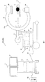
まず、図1に基づいて、本発明を適用したCアームシステムの概略構成について説明する。図1は、本実施形態に係るCアームシステムの概略構成を示す説明図である。 First, a schematic configuration of a C-arm system to which the present invention is applied will be described with reference to FIG. FIG. 1 is an explanatory diagram showing a schematic configuration of a C-arm system according to the present embodiment.
図1に示すCアームシステム100は、使用時に保管場所から手術室に搬送され、手術台2上で手術中の被検体3の患部のX線透視撮影を行う装置である。Cアームシステム100は、X線画像を表示するモニタ12を搭載したモニタ台車11と、X線源34を搭載するCアーム台車31と、を備え、これらモニタ台車11及びCアーム台車31は、ケーブル20により電気的に接続される。
A C-
モニタ台車11は、タッチパネル付きディスプレイからなるモニタ12、モニタ台車11内の各構成部品の制御を行うモニタ制御部13、及び外部電源50に接続される電源部14を備える。外部電源50は、商用交流電源であってもよい。またモニタ台車11には、後に詳述するが、モニタ12やモニタ制御部13等の負荷回路をバッテリ駆動するためのバッテリが搭載されている。
The
Cアーム台車31は、移動用の車輪、例えば、1個の前輪と2個の後輪を備えた台座と、その上に固定された本体部31aと、撮像部31bとを備える。本体部31aは、操作部37、制御部38、電源部39、及び画像処理部40などを収納する筐体で、移動用ハンドル41が設けられている。撮像部31bは、主として、Cアーム33と、Cアーム33の一端に固定されたX線源34と、Cアーム33の他端に受像部支持部35を介して固定されたX線平面検出器(フラットパネルディテクタ、以下、FPDと記す。)36とを備え、Cアーム支持部32によって本体部31aの筐体上部に支持されている。
The C-
Cアーム支持部32には、詳細な図示を省略されているが、Cアーム33をCアームの円弧方向にスライド移動(矢印A方向)させる旋回機構と、Cアーム33を水平方向に直線的に移動(矢印B方向)させる前後動機構と、Cアーム33を垂直方向に上下動させる(矢印C方向)昇降動機構と、Cアーム33を回転させる(矢印D方向)回転機構とを備えている。
Although not shown in detail in the C
Cアーム33は、X線源34とFPD36とを、それらが対向するように支持するとともに、Cアーム支持部32の上記4つの移動機構によって被検体2に対するX線照射方向を可変設定するものである。
The
X線源34は、被検体3へX線を照射する、いわゆるモノタンク型X線発生装置であり、X線遮蔽容器内にX線管球及び高電圧発生器(高圧変圧器、高圧整流器)を収納して構成される。X線は、電源部39から出力された高周波電圧(交流電圧)が高圧変圧器で昇圧され、高圧整流器を介して直流高電圧に変換されてX線管球へ印加されることで発生する。
The
FPD36は、X線を光に変換する蛍光体(シンチレータ)と、光電変換素子、例えばフォトトランジスタやフォトダイオードのような半導体光電変換素子とから成るX線検出素子を多数、2次元平面上に配列して成るX線検出器である。このFPD36は、受像部支持部35を介してCアーム33の一端へ取り付けられている。FPD36は、X線検出素子が行×列の2次元マトリクス状に配置されている。そして、FPD36はX線源34から被検体3へX線が照射されると、被検体3を透過したX線を上記X線検出素子で電流に変換して検出し、デジタルX線画像データを画像処理部40へ出力するように構成される。
The FPD 36 includes a large number of X-ray detection elements arranged on a two-dimensional plane, including a phosphor (scintillator) that converts X-rays into light and photoelectric conversion elements, for example, semiconductor photoelectric conversion elements such as phototransistors and photodiodes. This is an X-ray detector. The FPD 36 is attached to one end of the
操作部37は、透視及び撮影パラメータの入力器、術式選択器、透視及び撮影の操作器又はスイッチ、画質調整器等を備えている。透視及び撮影のパラメータを設定するための入力器としては、管電圧(kV)、管電流(mA)並びに撮影時間(ms)又は管電流撮影時間積(mAs)の設定器が設けられている。また、透視及び撮影の操作器として、透視時にX線照射を行うフットペダルや、撮影時にX線照射を行うハンドスイッチを備える。更にCアーム33をモータ駆動により移動させる上下動スイッチが含まれる。
The
電源部39は、バッテリを内蔵する。そして、このバッテリから供給される電力をインバータ回路(図示を省略)で高周波電圧に変換して、上記X線源34へ電力を供給する周知の構成と成っている。
The
画像処理部40は、FPD36から入力したデジタルX線画像データに対して種々の画像処理又は設定を行うもので、例えばガンマカーブの可変設定機能、ノイズ低減機能、輪郭強調、拡大処理等の画質調整機能の他に、ラストイメージホールド機能を備えている。これらの諸機能のうち、ラストイメージホールド機能は、周知のように、透視をオフするとその最終画像をメモリへ格納するとともに再生し、静止画像としてモニタへ表示する機能である。
The
移動用ハンドル41は、本体部31aの筐体上部に設けられた一対の移動操作用のハンドルから成り、このハンドルの一方へ加える力を他方のハンドルへ加える力より大きくすると、後輪のステアリング機能により、Cアーム台車31の進行方向が変化するようになっている。
The moving
タッチパネル付きディスプレイ12は、モニタ台車11によってX線装置とともに手術室へ搬送され、画像処理部40から出力された画像を表示して手術者に提供するものである。そして、タッチパネル付きディスプレイ12は、本実施形態では画面上の任意の位置を触れることで画像の表示方向を入力することが可能となっている。
The
本実施形態のCアームシステム100は、撮像部31bが待機状態にあるときに、モニタ台車11が接続されている外部電源50を利用して、撮像部31bの電源部39を充電し、充電待ちによる検査の滞りを回避することを特徴としている。
The C-
<第一実施形態>
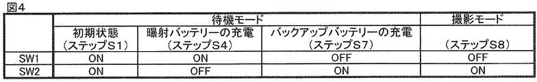
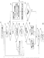
第一実施形態は、Cアーム台車31側で比較的大きな電力が必要な動作をする場合に、モニタ台車内のバッテリを使って、モニタ台車内をバッテリ駆動にし、モニタ台車11に供給予定だった電力を、Cアーム台車31に分配することで、Cアーム台車31に使用可能な電力を増加させる。以下、図2乃至図4に基づいて、第一実施形態について説明する。図2は、第一実施形態に係るCアームシステムの内部構成を示す機能ブロック図である。図3は、第一実施形態に係る処理の流れを示すフローチャートである。図4は、第一実施形態における第一スイッチング回路及び第二スイッチング回路の切替動作を示す説明図である。
<First embodiment>
In the first embodiment, when an operation requiring a relatively large amount of power is performed on the C-
まず、図2に基づいて、本実施形態に係るCアームシステム100の内部構成について説明する。図2において、実線は電力線を示し、点線は信号線を示す。
First, the internal configuration of the C-
Cアーム台車31の電源部39(図1)は、モニタ台車11への接続端子391と、モニタ台車11を経由して外部電源からの電圧を、Cアーム台車31に適した電圧に変換する第一電圧変換回路392と、第一電圧変換回路392に接続された充電回路393と、充電回路393に接続され、通電のON/OFFを切り替える第一スイッチング回路(図2では「SW1」と記載する)394と、第一スイッチング回路394に接続され、充電回路393及び第一スイッチング回路394を介して受電した電力を蓄電し、X線源34に供給する曝射バッテリ395と、を備える。X線源34(図1)は高電圧発生器342及びX線管球341を備える。
The power supply unit 39 (FIG. 1) of the C-
第一電圧変換回路392には、Cアーム台車31に搭載された、X線源34以外の電力負荷回路(第一負荷回路)400が接続されている。第一負荷回路400は、例えば、Cアーム台車31に搭載された画像処理部40、FPD36の受光部、Cアーム33の上下動、前後動等の移動を行うアーム移動装置(図示を省略)などが含まれる。
第一スイッチング回路394は、後述する制御部(フィードバック制御部)13からの信号により制御されてON/OFFが切り替えられる。第一スイッチング回路394がONの場合には、曝射バッテリ395は充電状態、OFFの場合には非充電状態となる。
曝射バッテリ395は、非充電状態のときに、X線源34の高電圧発生器342に所定の電力を供給し、X線源34をバッテリ駆動する。本実施形態では、曝射バッテリ395の充電状態では、X線源34は動作しない。すなわち、X線源34が非動作時のみに曝射バッテリ395の充電が行われる。
A power load circuit (first load circuit) 400 other than the
The
The
Cアーム台車31の制御部38は、操作部37から入力されたX線照射条件に従って、高電圧発生器342を制御し、X線照射条件にあったX線を照射するための制御を行なうための高電圧回路制御部381を備える。
The
モニタ台車11の電源部14(図1)は、外部電源50への接続端子141と、外部電源50をモニタ台車11に適した電力へ変換する第二電圧変換回路142と、その第二電圧変換回路142に接続され、通電のON/OFFを切り替える第二スイッチング回路(図2では「SW2」と記載する)143と、第二スイッチング回路143に接続された蓄電部(144〜146)とを備える。蓄電部は、モニタ台車側の電力負荷回路(第二負荷回路) 150に接続される。第二負荷回路150は、例えば、モニタ台車11に搭載されるモニタ(タッチパネルディスプレイ)12やモニタ制御部13など電力供給を受けて動作する要素である。さらに、モニタ台車11には、Cアーム台車31への接続端子147が設けられており、第二電圧変換回路142を接続端子147及びケーブル20を介して、Cアーム台車31の第一電圧変換回路392に接続している。
The power supply unit 14 (FIG. 1) of the
第二スイッチング回路143は、後述する制御系(フィードバック制御部)からの信号により制御されてON/OFFが切り替えられる。第二スイッチング回路143がONのときに、第二電圧変換回路142から蓄電部への充電と第二負荷回路150への給電が行われる。第二スイッチング回路143がOFFのときは、第二電圧変換回路142からの電力はCアーム台車31側に供給される。本実施形態では、第二スイッチング回路143は、Cアーム台車31の曝射バッテリ395への充電時のみOFFとなる。
The
蓄電部は、図示する実施形態では、第二スイッチング回路143と第二負荷回路150との間に挿入された整流器144と、第二負荷回路150に接続されたバックアップコンデンサ145と、バックアップコンデンサ145と並列に接続された電圧検出回路146と、を備える。なお蓄電部はバックアップコンデンサに代えて、バッテリ及び充電回路を用いて構成してもよい。
整流器144は、バックアップコンデンサ145から第二電圧変換回路142に電流が逆流するのを防止するもので、半導体ダイオード等の整流素子が用いられる。バックアップコンデンサ145は、外部電源からの給電が停止したときに第二負荷回路150を駆動するものである。電圧検出回路146は、バックアップコンデンサ145の残量を検出し、その結果を制御部13に送る。
In the illustrated embodiment, the power storage unit includes a
The
Cアームシステムは、制御系として、第一スイッチング回路394及び第二スイッチング回路143を制御するフィードバック制御部131を備える。フィードバック制御部131は、Cアーム台車31の操作部37に接続され、操作部37の画面遷移をトリガーとして、Cアームシステム100の待機モード及び撮影モードを判断する。また電圧検出回路146による検出結果に基づいて、第一スイッチング回路394及び第二スイッチング回路143のON/OFFを切り替える。なお図2に示す実施形態では、モニタ台車11の制御部13がフィードバック制御部131を備える構成を示しているが、Cアーム台車31の制御部38がフィードバック制御部131を備えていてもよい。
The C-arm system includes a
次に、図3の各ステップ順に沿って、第一実施形態に係るCアームシステムの動作の処理の流れについて説明する。 Next, the process flow of the operation of the C-arm system according to the first embodiment will be described along the order of steps in FIG.
(ステップS1)
外部電源(商用電源)50に接続端子141を接続するとモニタ台車11の電源部とCアーム台車31の電源部が通電状態となる。Cアーム台車31は、モニタ台車11の接続端子147、ケーブル20、及びCアーム台車31の接続端子391を経由して、外部電源50から受電する。この状態で、操作者は、操作部37に備えられた主電源スイッチを操作し、Cアームシステムを起動する(S0)。Cアームシステム100は、起動直後、待機モードの初期状態となる(S1)。初期状態では、第一スイッチング回路394及び第二スイッチング回路143は、ともにONとなる(図4参照)。
(Step S1)
When the
(ステップS2)
Cアームシステム100が撮影モードに移行するか否かで分岐する(S2)。撮影モードに移行しない場合は待機モードのままステップS3へ進み、バックアップコンデンサ145及び曝射バッテリ充電のための処理(S3、S4、S7)が行われる。撮影モードに移行する場合はステップS8へ進む。
(Step S2)
The process branches depending on whether or not the C-
(ステップS3)
フィードバック制御部131は、電圧検出回路146の検出結果を参照し、モニタ台車11のバックアップコンデンサ145の残量が正常であるか否か、換言すると、電圧が予め定められた閾値以上有るかどうかを判断する(S3)。バックアップコンデンサ145の電圧が、閾値以上であればステップS4へ進み、閾値未満であればステップS7へ進む。
(Step S3)
The
(ステップS4)
曝射バッテリの充電を行う(S4)。このため、フィードバック制御部131は、第一スイッチング回路394をON、第二スイッチング回路143をOFFに切り替える(図4参照)。これにより、モニタ台車11の第二負荷回路(モニタやモニタ制御回路)150は、バックアップコンデンサ145からの給電により動作可能な状態となる。また、曝射バッテリ395への充電が開始する。曝射バッテリ395への充電は、操作部37を介してシステム終了の指示(S5)または撮像開始の指示(S2)があるまで続けられる。この状態では、Cアーム台車31の第一負荷回路(アーム駆動機構等)400は第一電圧変換回路392からの給電により動作可能な状態であり、X線照射以外の動作、例えばアーム移動等は可能な状態になっている。
(Step S4)
The exposure battery is charged (S4). For this reason, the
(ステップS5、S6)
Cアームシステム100を終了するか否かにより処理が分岐する(S5)。「肯定」の場合は、主電源スイッチをOFFにしてシステムを終了する(S6)。「否定」の場合は、ステップS2へ戻る。
(Steps S5 and S6)
The process branches depending on whether the C-
(ステップS7)
バックアップコンデンサの電圧が閾値未満の場合であり(S3)、バックアップコンデンサ145の充電を行う(S7)。このためフィードバック制御部131は、第二スイッチング回路143をONに、第一スイッチング回路394をOFFに切り替える(図4参照)。これにより、バックアップコンデンサ145に突入電流が流れ込み、バックアップコンデンサ145が充電される。
(Step S7)
This is a case where the voltage of the backup capacitor is less than the threshold value (S3), and the
バックアップコンデンサ145への充電状態においても、第二負荷回路150は外部電源50からの給電で動作できる。具体的には、第二負荷回路150は、より近い位置にある電源から給電を受けるので、第二スイッチング回路143がONになっても、バックアップコンデンサ145からの給電で駆動するが、バックアップコンデンサ145には、第二負荷回路150に給電した電力が瞬時に充電される。このような、第二負荷回路150による消費電力が瞬時にバックアップコンデンサ145に補充される状態は、外部電源50からの給電駆動とみなすことができる。
Even when the
このようにバックアップコンデンサ145が充電されている間、曝射バッテリ395への充電は停止する。すなわち、バックアップコンデンサ145の電圧が閾値未満の場合には、バックアップコンデンサ145への充電が優先して行われる。その後、ステップS1へ戻る。
Thus, while the
なお上記説明では、ステップS7において、バックアップコンデンサ145を充電する場合に第一スイッチング回路394をOFFにしたが、バックアップコンデンサ145の充電に要する消費電力が相対的に小さかったり、曝射バッテリ395に満量の充電が行われている場合、第一スイッチング回路394をOFFにしなくてもよい。
In the above description, the
(ステップS8)
「撮影モード」は、静止画像を取得する「撮影」、及び動画像を取得する「透視」の少なくとも一つを実行するモードである。撮影モードへの移行は、操作者が操作部37の表示画面を撮影条件入力用の画面に遷移させたことをトリガーとして、フィードバック制御部131が判断する。撮影モードに移行すると、フィードバック制御部131は、第二スイッチング回路143をON、第一スイッチング回路394をOFFに切り替え、X線照射への準備(放電)に備える(S8)。直前のステップで曝射バッテリ395への充電を行っていた場合(S4)には、曝射バッテリ395への充電を停止して、放電可能な状態とする。これにより曝射バッテリ395から高電圧発生器342への電力供給が開始する。また第一負荷回路400は、第一電圧変換回路392からの給電を受け、動作可能な状態となっている。
(Step S8)
The “shooting mode” is a mode in which at least one of “shooting” for acquiring a still image and “perspective” for acquiring a moving image is executed. The shift to the shooting mode is determined by the
一方、モニタ台車側では、第二スイッチング回路143がONになったことで、第二負荷回路150は、外部電源50からの給電で動作するとともに、バックアップコンデンサ145にも突入電流が流れ込み、バックアップコンデンサ145に充電される。
On the other hand, on the monitor cart side, since the
(ステップS9)
操作者がCアーム台車31に搭載された図示しないフットペダルや曝射スイッチを操作し、X線を照射して透視や撮影を開始、終了する(S9)。
(Step S9)
The operator operates a foot pedal and an exposure switch (not shown) mounted on the C-
(ステップS10)
撮影モードの終了後は、曝射バッテリ395の残量が次の透視や撮影を行うに十分か否か、すなわち充電が必要か否かで分岐する。「肯定」(充電要)であれば、上述のステップS3に進み、ステップS4又はステップS7が実行され、撮像(X線透視や撮影)によって残量が減った曝射バッテリ395の充電が行われる。「否定」(充電不要)であれば、ステップS5を経て、システム停止(S6)または待機モード(S2)に戻る。つまり撮影開始前や撮影終了後の待機モードでは、常にバックアップコンデンサ145と曝射バッテリ395が充電される状態にあり、ステップS2で撮影モードに移行する時点では、それぞれの負荷回路の動作に必要な電力を供給可能な状態になっている。
(Step S10)
After the photographing mode is finished, the process branches depending on whether or not the remaining amount of the
なお曝射バッテリ395の残量が十分か否かは、曝射バッテリ395に電圧検出回路を設けて、その出力から判断するようにしてもよいし、X線源の消費電力をもとに算出し、その結果から判断するようにしてもよい。
Whether or not the remaining amount of the
本実施形態によれば、モニタ台車にバックアップコンデンサを設けるとともに、モニタ台車に供給される外部電源からの電力をCアーム台車に分配する構成としたことにより、システムの待機状態では、モニタ台車をバッテリ駆動しながら曝射バッテリへの充電を行うことができる。これにより、曝射バッテリへの充電を待つために検査が中断するといったシステムのダウンタイムの短縮化が図れ、検査のスループットの向上が期待できる。 According to the present embodiment, a backup capacitor is provided in the monitor cart, and power from an external power source supplied to the monitor cart is distributed to the C-arm cart. While driving, the exposure battery can be charged. As a result, the system downtime can be shortened such that the inspection is interrupted in order to wait for the exposure battery to be charged, and an improvement in inspection throughput can be expected.
上記各ステップの順序は、一例に過ぎず、本発明の趣旨を逸脱しない範囲で、様々な変更態様がありうる。例えば、通常、Cアームシステムの起動直後(S0)は、待機モードとなるので、図3のステップS2の前に、必ずステップS3、S4、S5、S7のループを行ってから、撮影モードか否かの判断処理(S2)を行うように構成してもよい。 The order of the above steps is merely an example, and various modifications can be made without departing from the spirit of the present invention. For example, since the standby mode is normally performed immediately after the C-arm system is started (S0), the loop of steps S3, S4, S5, and S7 is always performed before step S2 in FIG. The determination process (S2) may be performed.
また、ステップS5でシステム終了の判断がされた後、次の使用時に備えて、バックアップコンデンサ145及び曝射バッテリ395の双方に撮影モードへの移行に十分な程度の蓄電がされてからシステムが停止(S6)するように構成してもよい。
In addition, after it is determined in step S5 that the system has been terminated, the system stops after the
更に、Cアームシステムの起動直後(S0)に撮影モードに移行した場合に、ステップS8の前にバックアップコンデンサ145及び曝射バッテリ395の残量チェックを実行し、これらに透視・撮影に必要な電力を確保してからステップS8を実行するように構成してもよい。
Further, when the mode is shifted to the shooting mode immediately after the C-arm system is started (S0), the remaining capacity of the
また本実施形態では、第一スイッチング回路394のON/OFFの制御をバックアップコンデンサの電圧に応じて、フィードバック制御部131が行う場合を示したが、例えば、第一スイッチング回路394のON/OFFの制御をX線曝射(高電圧発生器342の駆動)と連動させて、撮影モードにおいてもX線曝射が行われない間は第一スイッチング回路394をONにして、充電回路393から曝射バッテリ395への充電が行われるように構成することも可能である。
In the present embodiment, the
<第二実施形態>
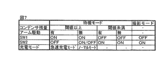
第二実施形態は、Cアーム台車の透視・撮影以外の動作の有無に応じて、曝射バッテリの充電モードを標準速度で充電するノーマルモードと、標準速度よりも速い速度で充電する急速充電モードと、に切り替える実施形態である。本実施形態は、Cアーム台車の透視・撮影以外の動作の例として、Cアームの上下動(図1における矢印C方向の動作)をモータ駆動する構成を例に挙げて説明する。ただし、充電モード切替判断の対象となる動作は、Cアームの上下動動作に限らず、消費電力の多少に応じて決定してもよい。以下、図5乃至図7に従って、第二実施形態について説明する。図5は、第二実施形態に係るCアームシステムの内部構成を示す機能ブロック図である。図6は、第二実施形態に係る処理の流れを示すフローチャートである。図7は、第二実施形態における第一スイッチング回路及び第二スイッチング回路の切替動作及び充電モードを示す説明図である。
<Second embodiment>
In the second embodiment, a normal mode in which the charging mode of the exposure battery is charged at a standard speed and a quick charge mode in which the charging speed is higher than the standard speed depending on whether the C-arm carriage is operated other than fluoroscopic / photographing. It is an embodiment to switch to. In the present embodiment, as an example of operations other than the fluoroscopic / photographing of the C-arm carriage, a configuration in which the C-arm is vertically driven (operation in the direction of arrow C in FIG. 1) will be described as an example. However, the operation to be determined for the charging mode switching is not limited to the vertical movement operation of the C-arm, but may be determined according to the amount of power consumption. Hereinafter, the second embodiment will be described with reference to FIGS. FIG. 5 is a functional block diagram showing the internal configuration of the C-arm system according to the second embodiment. FIG. 6 is a flowchart showing a flow of processing according to the second embodiment. FIG. 7 is an explanatory diagram illustrating a switching operation and a charging mode of the first switching circuit and the second switching circuit in the second embodiment.
図5に示すように、第二実施形態に係るCアームシステム200では、第一実施形態の第一負荷回路400の代わりに、Cアームをモータ駆動させるアーム駆動装置420を備え、アーム駆動装置420は、第一電圧変換回路392から給電されて駆動する。更に、アーム駆動装置420の動作制御を行うアーム制御部421を備える。アーム制御部421は、操作部37に含まれる図示しないアーム昇降スイッチ、及びアーム駆動装置420に接続される。
As shown in FIG. 5, the
また、Cアーム台車31の制御部38は、充電回路393に対し、充電速度の切替制御を行う充電制御部382を備える。充電制御部382は、操作部37に含まれる図示しないアーム昇降スイッチ、及び充電回路393に接続される。そして、充電制御部382は、アーム昇降スイッチからのアーム昇降動作の入力信号の有無に従って、ノーマルモード又は急速充電モードに切り替える。
In addition, the
第二実施形態の処理の流れを、図6を参照して説明する。図6において、図3と同じ処理内容のステップは同一の符号で示し、その詳しい説明は省略する。 The process flow of the second embodiment will be described with reference to FIG. 6, steps having the same processing contents as those in FIG. 3 are denoted by the same reference numerals, and detailed description thereof is omitted.
本実施形態においても、Cアームシステム起動後、撮影モードに移行するまでは待機モードであること、及び、初期状態の待機モードでは第一スイッチング回路394及び第二スイッチング回路143はともにONであることは、第一実施形態と同様である(S0、S2)(図7参照)。また撮影モードに移行した後のステップS8〜S10も第一実施形態と同様である。
本実施形態では、待機モードにおいて、Cアームの昇降動作の有無により、曝射バッテリ395への充電を比較的低速で行う「ノーマルモード」と比較的高速で行う「急速充電モード」に切り替えて、行うことが特徴である。以下、各ステップを詳述する。
Also in this embodiment, after the C-arm system is activated, the standby mode is set until the shooting mode is entered, and the
In the present embodiment, in the standby mode, the
(ステップS3)
フィードバック制御部131は、電圧検出回路146の検出結果を参照し、モニタ台車11のバックアップコンデンサ145の残量が正常であるか否か、換言すると、電圧が予め定められた閾値以上有るかどうかを判断する(S3)。バックアップコンデンサ145の電圧が、閾値以上であればステップS41へ進み、閾値未満であればステップS7へ進む。
(Step S3)
The
(ステップS40、S41)
第2スイッチング回路143をOFF、第1スイッチング回路394をONにして、曝射バッテリへの充電に備える(S40)。充電制御部382が、操作部37からの入力信号の有無に基づいて、Cアーム33の昇降動作の有無を判断する(S41)。Cアーム33の昇降動作があれば、ステップS42に進み、昇降動作がない場合には、ステップS43に進む。
(Steps S40 and S41)
The
(ステップS42)
Cアーム33の昇降動作があると、Cアーム台車31側では第一電圧変換回路392からアーム駆動装置420に比較的大きな電力を供給する必要がある。充電制御部382は、充電回路393に対して、充電速度を標準速度に設定する指示信号を出力し、ノーマルモードにより曝射バッテリ395を充電する。その後、システム終了でなければ待機モード(S1)に戻る。
(Step S42)
When the
(ステップS43)
Cアーム33の昇降動作がなければ、充電制御部382は、充電回路393に対して、充電速度を急速に設定する指示信号を出力し、急速充電モードにより曝射バッテリ395を充電する。その後、システム終了でなければ待機モード(S3)に戻る。
(Step S43)
If the
本実施形態によれば、曝射バッテリの充電を行う際に、アームの昇降動作の有無に応じて、充電速度を切り替えることができる。これにより、曝射バッテリ以外の負荷回路で電力を消費しないときに曝射バッテリを高速充電し、システムのダウンタイムをさらに短縮化できる。 According to this embodiment, when charging the exposure battery, the charging speed can be switched depending on whether the arm is lifted or lowered. As a result, when no power is consumed by a load circuit other than the exposure battery, the exposure battery can be charged at high speed, and the system downtime can be further shortened.
なお図7の実施形態では、撮影モードにおいては、第一スイッチング回路394をOFFにする場合を示しているが、第一スイッチング回路394のON/OFFの制御をX線曝射(高電圧発生器342の駆動)と連動させて、撮影モードにおいてもX線曝射が行われない間は第一スイッチング回路394をONにして、充電回路393から曝射バッテリ395への充電が行われるように構成することも可能である。
In the embodiment of FIG. 7, in the imaging mode, the case where the
<第三実施形態>
本実施形態は、撮影モードが静止画像を取得する「撮影」か、動画像を取得する「透視」かによって第二スイッチング回路143のON/OFFを切り替える実施形態である。一般に「透視」はCアームの移動動作を伴い且つ連続的にX線曝射が行われるため、大きな電力を要する。本実施形態では、撮影モードの処理内容に応じて第二スイッチング回路のON/OFFを制御し、商用電源50からの電力を効率的に分配することが特徴である。
<Third embodiment>
In the present embodiment, the
本実施形態のCアームシステムの構成は、図2または図5の機能ブロック図に示す構成と同様であり図示を省略する。以下の説明では、図5を流用して、Cアームの昇降動作も考慮した制御を行う実施形態を説明する。図8に、第三実施形態に係る撮像モードの処理の流れを示すが、待機モードについては、図3または図6に示す待機モードの処理と同様であるので図示及び説明を省略する。 The configuration of the C-arm system of the present embodiment is the same as the configuration shown in the functional block diagram of FIG. 2 or FIG. In the following description, an embodiment will be described in which control is performed in consideration of the raising / lowering operation of the C-arm with reference to FIG. FIG. 8 shows the flow of processing in the imaging mode according to the third embodiment. Since the standby mode is the same as the processing in the standby mode shown in FIG. 3 or FIG.
(ステップS80)
操作部37を介して選択された撮影モードが「撮影」か「透視」かによって分岐する。「透視」の場合は、ステップS81に進み、「撮影」の場合は、ステップS82に進む。
(Step S80)
The operation branches depending on whether the shooting mode selected via the
(ステップS81)(透視)
充電制御部382が、操作部37からの入力信号の有無に基づいて、Cアーム33の昇降動作の有無を判断する。Cアーム33の昇降動作があれば、ステップS831に進み、昇降動作がない場合には、ステップS832に進む。
(Step S81) (Transparent)
Based on the presence / absence of an input signal from the
(ステップS831)
フィードバック制御部131は、第二スイッチング回路143、第一スイッチング回路394をともにOFFに切り替え、X線照射への準備(放電)に備える。直前のステップで曝射バッテリ395への充電を行っていた場合には、曝射バッテリ395への充電を停止して、放電可能な状態とする。これにより曝射バッテリ395から高電圧発生器342への電力供給が開始する。またアーム駆動装置420は、第一電圧変換回路392からの給電を受け、動作可能な状態となっている。
(Step S831)
The
一方、モニタ台車側では、第二スイッチング回路143がOFFになったことで、第二負荷回路150は、バックアップコンデンサ145によるバッテリ駆動される。これにより大電力を必要とするCアーム駆動とX線曝射とを同時に行いながら、透視を進めることができる。
On the other hand, on the monitor cart side, the
(ステップS832)
フィードバック制御部131は、第二スイッチング回路143をON、第一スイッチング回路394をONにし、X線照射への準備(放電)に備える。Cアーム33が駆動されないので、第二電圧変換回路392からの突入電流がバックアップコンデンサ145に流れ、バックアップコンデンサに充電されるとともに、モニタ台車側の第二負荷回路150は外部電源50からの給電で動作する。
(Step S832)
The
(ステップS82)(撮影)
ステップS832と同様に、第二スイッチング回路143をON、第一スイッチング回路394をOFFにし、X線照射への準備(放電)に備える。「撮影」は、「透視」に比べ短時間で撮影できるので、Cアーム駆動の有無にかかわらず第二スイッチング回路143をONにして、モニタ台車側のバックアップコンデンサ145への充電を行いながら、Cアーム台車側は、分配された電力で必要に応じてCアーム駆動を行う。
(Step S82) (Photographing)
As in step S832, the
なお「撮影」の場合にも、図8に点線で示すように、Cアームの動作有無を判断し(S841)、それによって第二スイッチング回路143のON/OFFを制御することも可能である。この場合には、例えば、Cアームの動作がない場合には、ステップS82に進む。Cアームの動作がある場合には、ステップS842に進む。
In the case of “photographing”, as shown by a dotted line in FIG. 8, it is possible to determine whether the C-arm is in operation (S841), thereby controlling ON / OFF of the
ステップS842で、フィードバック制御部131は、検出回路146が検出したバックアップコンデンサ145の残量が正常であるか否か、電圧が予め定められた第一閾値以上有るかどうかを判断し、バックアップコンデンサ145の残量が正常であれば第二スイッチング回路143をOFF、第一スイッチング回路394をOFFに切り替え、X線照射への準備(放電)に備える(S843)。この場合には、モニタ台車側の第二負荷回路150はバッテリ駆動され、外部電源50からの電力はすべてCアーム側に供給される。これによりCアーム駆動と「撮影」を順次行うことができる状態となる。
In step S842, the
またバックアップコンデンサ145の残量が少ない場合には、ステップS82に進み、バックアップコンデンサ145への充電を行いながら、Cアーム台車側は、分配された電力でCアーム駆動を行う。
When the remaining amount of the
(ステップS91、S92)
透視または撮影を実行する。その後のステップS10は、図3及び図6に示すステップS9、S10と同様であり説明を省略する。
本実施形態によれば、撮影モードの処理内容に応じて第二スイッチング回路143を切り替えることにより、電力に制限のある外部電源を効率よく分配して、円滑な検査を行うことができる。
(Steps S91, S92)
Perform fluoroscopy or filming. Subsequent step S10 is the same as steps S9 and S10 shown in FIGS. 3 and 6, and a description thereof will be omitted.
According to the present embodiment, by switching the
本発明によれば、モニタ台車側に供給される外部電源からの電力を、効率的にCアーム台車を分配することによって、曝射バッテリの充電のためにシステムのダウンタイムが生じるのを極力回避し、円滑な検査を実現できる。 According to the present invention, the power from the external power source supplied to the monitor carriage side is efficiently distributed to the C-arm carriage, thereby avoiding system downtime as much as possible to charge the exposure battery. And smooth inspection can be realized.
100、200・・・Cアームシステム、11・・・モニタ台車、13・・・モニタ制御部、20・・・ケーブル、31・・・Cアーム台車、33・・・Cアーム、34・・・X線源、37・・・操作部、38・・・制御部、39・・・電源部、40・・・画像処理部、50・・・外部電源、131・・・フィードバック制御部、142・・・第二電圧変換回路(モニタ台車側電源部)、143・・・第二スイッチング回路、145・・・バックアップコンデンサ(第二蓄電部)、146・・・電圧検出回路(検出部)、150・・・第二負荷回路、341・・・X線管、381・・・高電圧、392・・・第二電圧変換回路(Cアーム台車側電源部)、393・・・充電回路、394・・・第一スイッチング回路、395・・・曝射バッテリ(第一蓄電部)、400・・・第一負荷回路、420・・・アーム駆動装置。
DESCRIPTION OF
Claims (8)
前記X線源と、
外部電源から受電して、前記X線源に印加する電力を蓄える第一蓄電部と、
前記第一蓄電部に対し、前記外部電源からの給電のON/OFFを切り替える第一スイッチング回路と、
前記X線源と異なる負荷回路と、
前記外部電源から受電して、前記負荷回路に給電する電力を蓄える第二蓄電部と、
前記負荷回路、及び前記第二蓄電部に対し、前記外部電源からの給電のON/OFFを切り替える第二スイッチング回路と、
前記第二蓄電部に蓄電された電力の残量を検出する検出部と、
前記検出部による検出結果に基づいて、前記第一スイッチング回路及び前記第二スイッチング回路のON/OFFの切替制御を行うフィードバック制御部と、を備え、
前記フィードバック制御部は、前記第二蓄電部に蓄電された電力の残量が所定の閾値以上である場合に、前記第一スイッチング回路をONに切り替えて前記第一蓄電部の充電を行うとともに、前記第二スイッチング回路をOFFに切り替えて、前記負荷回路を前記第二蓄電部からの給電により駆動させることを特徴とするX線画像診断装置。 An X-ray source;
The X-ray source;
A first power storage unit that receives power from an external power source and stores electric power applied to the X-ray source;
A first switching circuit that switches ON / OFF of power feeding from the external power supply to the first power storage unit;
A load circuit different from the X-ray source;
A second power storage unit that receives power from the external power source and stores power to be fed to the load circuit;
A second switching circuit that switches ON / OFF of power feeding from the external power source for the load circuit and the second power storage unit;
A detection unit for detecting a remaining amount of power stored in the second power storage unit;
A feedback control unit that performs ON / OFF switching control of the first switching circuit and the second switching circuit based on a detection result by the detection unit;
The feedback control unit turns on the first switching circuit to charge the first power storage unit when the remaining amount of power stored in the second power storage unit is equal to or greater than a predetermined threshold, An X-ray diagnostic imaging apparatus, wherein the second switching circuit is switched to OFF and the load circuit is driven by power feeding from the second power storage unit.
前記フィードバック制御部は、前記第二蓄電部に蓄電された電力の残量が前記第一閾値未満である場合に、前記第一スイッチング回路をOFF、前記第二スイッチング回路をONに切り替えて前記第二蓄電部への充電を行うことを特徴とするX線画像診断装置。 The X-ray diagnostic imaging apparatus according to claim 1,
The feedback control unit switches the first switching circuit to OFF and the second switching circuit to ON when the remaining amount of electric power stored in the second power storage unit is less than the first threshold value. An X-ray diagnostic imaging apparatus characterized by charging two power storage units.
X線画像を表示する表示部を更に備え、
前記負荷回路は、前記表示部を含むことを特徴とするX線画像診断装置。 The X-ray diagnostic imaging apparatus according to claim 1 or 2,
A display unit for displaying an X-ray image;
The X-ray diagnostic imaging apparatus, wherein the load circuit includes the display unit.
外部電源との接続端子を有し、表示装置を搭載したモニタ台車と、
前記アーム台車及び前記モニタ台車を電気的に接続するケーブルと、
前記アーム台車及び前記モニタ台車の駆動を制御する制御部と、を備え、
前記アーム台車は、外部電源から受電して、前記X線源に印加する電力を蓄える第一蓄電部と、前記第一蓄電部に対し、前記外部電源からの給電のON/OFFを切り替える第一スイッチング回路と、を備え、
前記モニタ台車は、前記表示装置を含む負荷回路と、前記外部電源から受電して、前記負荷回路に給電する電力を蓄える第二蓄電部と、前記負荷回路、及び前記第二蓄電部に対し、前記外部電源からの給電のON/OFFを切り替える第二スイッチング回路と、前記第二蓄電部に蓄電された電力の残量を検出する検出部と、を備え、
前記制御部は、前記検出部による検出結果に基づいて、前記第一スイッチング回路及び前記第二スイッチング回路のON/OFFの切替制御を行うフィードバック制御部を備えたことを特徴とするX線画像診断装置。 An arm carriage equipped with an X-ray source, an X-ray detector, and an arm unit for connecting and supporting the X-ray source and the X-ray detector opposite to each other;
A monitor cart having a connection terminal with an external power supply and equipped with a display device;
A cable for electrically connecting the arm carriage and the monitor carriage;
A control unit that controls driving of the arm carriage and the monitor carriage,
The arm carriage receives a power from an external power source and stores a power to be applied to the X-ray source, and a first power storage unit that switches ON / OFF of power feeding from the external power source to the first power storage unit. A switching circuit,
The monitor carriage includes a load circuit including the display device, a second power storage unit that receives power from the external power supply and supplies power to the load circuit, the load circuit, and the second power storage unit. A second switching circuit that switches ON / OFF of power supply from the external power source, and a detection unit that detects a remaining amount of power stored in the second power storage unit,
X-ray image diagnosis characterized in that the control unit includes a feedback control unit for performing ON / OFF switching control of the first switching circuit and the second switching circuit based on a detection result by the detection unit. apparatus.
前記フィードバック制御部は、前記第二蓄電部に蓄電された電力の残量が所定の閾値以上である場合に、前記第一スイッチング回路をONに切り替えて前記第一蓄電部の充電を行うとともに、前記第二スイッチング回路をOFFに切り替えて、前記負荷回路を前記第二蓄電部からの給電により駆動させることを特徴とするX線画像診断装置。 The X-ray diagnostic imaging apparatus according to claim 4,
The feedback control unit turns on the first switching circuit to charge the first power storage unit when the remaining amount of power stored in the second power storage unit is equal to or greater than a predetermined threshold, An X-ray diagnostic imaging apparatus, wherein the second switching circuit is switched to OFF and the load circuit is driven by power feeding from the second power storage unit.
前記アーム台車は、前記外部電源からの給電を受けてモータ駆動により前記アーム部を移動させるアーム駆動装置を備え、
前記制御部は、前記アーム駆動装置の動作の有無を判断し、判断結果に応じて、前記第一蓄電部に充電する速度を制御する充電制御部を備えることを特徴とするX線画像診断装置。 The X-ray image diagnostic apparatus according to claim 4 or 5,
The arm carriage includes an arm driving device that receives power from the external power source and moves the arm portion by motor driving,
The X-ray diagnostic imaging apparatus, wherein the control unit includes a charge control unit that determines whether or not the arm driving device is operating, and controls a speed at which the first power storage unit is charged according to a determination result. .
前記制御部は、静止画像を取得する撮影か動画像を取得する透視かを判断し、判断結果に応じて、前記第一スイッチング回路及び第二スイッチング回路のON/OFFを切り替えることを特徴とするX線画像診断装置。 The X-ray image diagnostic apparatus according to any one of claims 4 to 6,
The control unit determines whether shooting for acquiring a still image or fluoroscopy for acquiring a moving image, and switches ON / OFF of the first switching circuit and the second switching circuit according to a determination result. X-ray image diagnostic apparatus.
前記第二蓄電部は、整流器と、前記整流器と前記負荷回路との間に接続されたバックアップコンデンサとを用いて構成されることを特徴とするX線画像診断装置。 The X-ray diagnostic imaging apparatus according to any one of claims 1 to 7,
The X-ray diagnostic imaging apparatus, wherein the second power storage unit includes a rectifier and a backup capacitor connected between the rectifier and the load circuit.
Priority Applications (1)
| Application Number | Priority Date | Filing Date | Title |
|---|---|---|---|
| JP2013078691A JP2014200436A (en) | 2013-04-04 | 2013-04-04 | X-ray image diagnostic apparatus |
Applications Claiming Priority (1)
| Application Number | Priority Date | Filing Date | Title |
|---|---|---|---|
| JP2013078691A JP2014200436A (en) | 2013-04-04 | 2013-04-04 | X-ray image diagnostic apparatus |
Publications (1)
| Publication Number | Publication Date |
|---|---|
| JP2014200436A true JP2014200436A (en) | 2014-10-27 |
Family
ID=52351444
Family Applications (1)
| Application Number | Title | Priority Date | Filing Date |
|---|---|---|---|
| JP2013078691A Pending JP2014200436A (en) | 2013-04-04 | 2013-04-04 | X-ray image diagnostic apparatus |
Country Status (1)
| Country | Link |
|---|---|
| JP (1) | JP2014200436A (en) |
Cited By (4)
| Publication number | Priority date | Publication date | Assignee | Title |
|---|---|---|---|---|
| JP2018000724A (en) * | 2016-07-06 | 2018-01-11 | 富士フイルム株式会社 | Radiation irradiation device |
| JP2019076638A (en) * | 2017-10-27 | 2019-05-23 | コニカミノルタ株式会社 | Radiation picture imaging system |
| JPWO2020035927A1 (en) * | 2018-08-16 | 2021-08-10 | 株式会社島津製作所 | Surgical mobile X-ray device |
| JP2022058864A (en) * | 2017-10-27 | 2022-04-12 | コニカミノルタ株式会社 | Radiation picture imaging system |
-
2013
- 2013-04-04 JP JP2013078691A patent/JP2014200436A/en active Pending
Cited By (8)
| Publication number | Priority date | Publication date | Assignee | Title |
|---|---|---|---|---|
| JP2018000724A (en) * | 2016-07-06 | 2018-01-11 | 富士フイルム株式会社 | Radiation irradiation device |
| JP2019076638A (en) * | 2017-10-27 | 2019-05-23 | コニカミノルタ株式会社 | Radiation picture imaging system |
| JP7020059B2 (en) | 2017-10-27 | 2022-02-16 | コニカミノルタ株式会社 | Radiation imaging system |
| JP2022058864A (en) * | 2017-10-27 | 2022-04-12 | コニカミノルタ株式会社 | Radiation picture imaging system |
| JP7276531B2 (en) | 2017-10-27 | 2023-05-18 | コニカミノルタ株式会社 | Radiation imaging system |
| JPWO2020035927A1 (en) * | 2018-08-16 | 2021-08-10 | 株式会社島津製作所 | Surgical mobile X-ray device |
| JP2022174223A (en) * | 2018-08-16 | 2022-11-22 | 株式会社島津製作所 | Mobile type x-ray apparatus for surgery |
| JP7409449B2 (en) | 2018-08-16 | 2024-01-09 | 株式会社島津製作所 | Surgical mobile X-ray device |
Similar Documents
| Publication | Publication Date | Title |
|---|---|---|
| JP5611213B2 (en) | Mobile X-ray device | |
| JP5460270B2 (en) | X-ray diagnostic equipment | |
| JP5442307B2 (en) | Mobile X-ray device | |
| JP2014200436A (en) | X-ray image diagnostic apparatus | |
| JP2010273827A (en) | Movable x-ray equipment and method for x-ray photographing of the same | |
| US20170215832A1 (en) | Radiographic image capturing system | |
| JP2009056066A (en) | X-ray ct apparatus and its control method | |
| JP6573026B2 (en) | X-ray equipment | |
| JPWO2014119164A1 (en) | Radiation imaging device | |
| JP6095281B2 (en) | X-ray generator and mobile X-ray imaging apparatus | |
| JP5685449B2 (en) | X-ray high voltage apparatus and X-ray CT apparatus | |
| JP4849170B2 (en) | X-ray control device | |
| JP2015198840A (en) | Radiation generating device | |
| JP6222378B2 (en) | X-ray equipment | |
| JP6172923B2 (en) | X-ray diagnostic imaging equipment | |
| JP2018033493A (en) | X-ray fluoroscopic imaging apparatus | |
| US20210212653A1 (en) | Radiography apparatus | |
| WO2020035927A1 (en) | Mobile x-ray device | |
| JP7163797B2 (en) | Charging control device and mobile radiography system | |
| JP5819136B2 (en) | X-ray equipment | |
| JP7055639B2 (en) | X-ray diagnostic device | |
| JP2014060023A (en) | X-ray high voltage generator, and mobile x-ray fluoroscopic imaging apparatus | |
| JP2022105408A (en) | Radiographic system and power feeding control method | |
| JP6463922B2 (en) | Radiation generator, radiation imaging system, radiation generator control method and program | |
| JP5405619B2 (en) | X-ray CT apparatus and control method thereof |