JP2014190763A - Battery lifetime estimation method and battery lifetime estimation device - Google Patents
Battery lifetime estimation method and battery lifetime estimation device Download PDFInfo
- Publication number
- JP2014190763A JP2014190763A JP2013064912A JP2013064912A JP2014190763A JP 2014190763 A JP2014190763 A JP 2014190763A JP 2013064912 A JP2013064912 A JP 2013064912A JP 2013064912 A JP2013064912 A JP 2013064912A JP 2014190763 A JP2014190763 A JP 2014190763A
- Authority
- JP
- Japan
- Prior art keywords
- battery
- deterioration
- temperature
- current
- period
- Prior art date
- Legal status (The legal status is an assumption and is not a legal conclusion. Google has not performed a legal analysis and makes no representation as to the accuracy of the status listed.)
- Pending
Links
Images


Classifications
-
- G—PHYSICS
- G01—MEASURING; TESTING
- G01R—MEASURING ELECTRIC VARIABLES; MEASURING MAGNETIC VARIABLES
- G01R31/00—Arrangements for testing electric properties; Arrangements for locating electric faults; Arrangements for electrical testing characterised by what is being tested not provided for elsewhere
- G01R31/36—Arrangements for testing, measuring or monitoring the electrical condition of accumulators or electric batteries, e.g. capacity or state of charge [SoC]
- G01R31/392—Determining battery ageing or deterioration, e.g. state of health
-
- B—PERFORMING OPERATIONS; TRANSPORTING
- B60—VEHICLES IN GENERAL
- B60L—PROPULSION OF ELECTRICALLY-PROPELLED VEHICLES; SUPPLYING ELECTRIC POWER FOR AUXILIARY EQUIPMENT OF ELECTRICALLY-PROPELLED VEHICLES; ELECTRODYNAMIC BRAKE SYSTEMS FOR VEHICLES IN GENERAL; MAGNETIC SUSPENSION OR LEVITATION FOR VEHICLES; MONITORING OPERATING VARIABLES OF ELECTRICALLY-PROPELLED VEHICLES; ELECTRIC SAFETY DEVICES FOR ELECTRICALLY-PROPELLED VEHICLES
- B60L58/00—Methods or circuit arrangements for monitoring or controlling batteries or fuel cells, specially adapted for electric vehicles
- B60L58/10—Methods or circuit arrangements for monitoring or controlling batteries or fuel cells, specially adapted for electric vehicles for monitoring or controlling batteries
- B60L58/16—Methods or circuit arrangements for monitoring or controlling batteries or fuel cells, specially adapted for electric vehicles for monitoring or controlling batteries responding to battery ageing, e.g. to the number of charging cycles or the state of health [SoH]
-
- G—PHYSICS
- G01—MEASURING; TESTING
- G01R—MEASURING ELECTRIC VARIABLES; MEASURING MAGNETIC VARIABLES
- G01R31/00—Arrangements for testing electric properties; Arrangements for locating electric faults; Arrangements for electrical testing characterised by what is being tested not provided for elsewhere
- G01R31/36—Arrangements for testing, measuring or monitoring the electrical condition of accumulators or electric batteries, e.g. capacity or state of charge [SoC]
- G01R31/367—Software therefor, e.g. for battery testing using modelling or look-up tables
-
- H—ELECTRICITY
- H01—ELECTRIC ELEMENTS
- H01M—PROCESSES OR MEANS, e.g. BATTERIES, FOR THE DIRECT CONVERSION OF CHEMICAL ENERGY INTO ELECTRICAL ENERGY
- H01M10/00—Secondary cells; Manufacture thereof
- H01M10/42—Methods or arrangements for servicing or maintenance of secondary cells or secondary half-cells
- H01M10/4285—Testing apparatus
-
- H—ELECTRICITY
- H01—ELECTRIC ELEMENTS
- H01M—PROCESSES OR MEANS, e.g. BATTERIES, FOR THE DIRECT CONVERSION OF CHEMICAL ENERGY INTO ELECTRICAL ENERGY
- H01M10/00—Secondary cells; Manufacture thereof
- H01M10/42—Methods or arrangements for servicing or maintenance of secondary cells or secondary half-cells
- H01M10/48—Accumulators combined with arrangements for measuring, testing or indicating the condition of cells, e.g. the level or density of the electrolyte
-
- H—ELECTRICITY
- H02—GENERATION; CONVERSION OR DISTRIBUTION OF ELECTRIC POWER
- H02J—CIRCUIT ARRANGEMENTS OR SYSTEMS FOR SUPPLYING OR DISTRIBUTING ELECTRIC POWER; SYSTEMS FOR STORING ELECTRIC ENERGY
- H02J7/00—Circuit arrangements for charging or depolarising batteries or for supplying loads from batteries
- H02J7/0047—Circuit arrangements for charging or depolarising batteries or for supplying loads from batteries with monitoring or indicating devices or circuits
- H02J7/005—Detection of state of health [SOH]
-
- G—PHYSICS
- G01—MEASURING; TESTING
- G01R—MEASURING ELECTRIC VARIABLES; MEASURING MAGNETIC VARIABLES
- G01R31/00—Arrangements for testing electric properties; Arrangements for locating electric faults; Arrangements for electrical testing characterised by what is being tested not provided for elsewhere
- G01R31/36—Arrangements for testing, measuring or monitoring the electrical condition of accumulators or electric batteries, e.g. capacity or state of charge [SoC]
- G01R31/389—Measuring internal impedance, internal conductance or related variables
-
- Y—GENERAL TAGGING OF NEW TECHNOLOGICAL DEVELOPMENTS; GENERAL TAGGING OF CROSS-SECTIONAL TECHNOLOGIES SPANNING OVER SEVERAL SECTIONS OF THE IPC; TECHNICAL SUBJECTS COVERED BY FORMER USPC CROSS-REFERENCE ART COLLECTIONS [XRACs] AND DIGESTS
- Y02—TECHNOLOGIES OR APPLICATIONS FOR MITIGATION OR ADAPTATION AGAINST CLIMATE CHANGE
- Y02E—REDUCTION OF GREENHOUSE GAS [GHG] EMISSIONS, RELATED TO ENERGY GENERATION, TRANSMISSION OR DISTRIBUTION
- Y02E60/00—Enabling technologies; Technologies with a potential or indirect contribution to GHG emissions mitigation
- Y02E60/10—Energy storage using batteries
-
- Y—GENERAL TAGGING OF NEW TECHNOLOGICAL DEVELOPMENTS; GENERAL TAGGING OF CROSS-SECTIONAL TECHNOLOGIES SPANNING OVER SEVERAL SECTIONS OF THE IPC; TECHNICAL SUBJECTS COVERED BY FORMER USPC CROSS-REFERENCE ART COLLECTIONS [XRACs] AND DIGESTS
- Y02—TECHNOLOGIES OR APPLICATIONS FOR MITIGATION OR ADAPTATION AGAINST CLIMATE CHANGE
- Y02T—CLIMATE CHANGE MITIGATION TECHNOLOGIES RELATED TO TRANSPORTATION
- Y02T10/00—Road transport of goods or passengers
- Y02T10/60—Other road transportation technologies with climate change mitigation effect
- Y02T10/70—Energy storage systems for electromobility, e.g. batteries
Landscapes
- Engineering & Computer Science (AREA)
- Manufacturing & Machinery (AREA)
- Chemical & Material Sciences (AREA)
- Chemical Kinetics & Catalysis (AREA)
- Electrochemistry (AREA)
- General Chemical & Material Sciences (AREA)
- Physics & Mathematics (AREA)
- Power Engineering (AREA)
- General Physics & Mathematics (AREA)
- Sustainable Development (AREA)
- Health & Medical Sciences (AREA)
- Medical Informatics (AREA)
- Life Sciences & Earth Sciences (AREA)
- General Health & Medical Sciences (AREA)
- Sustainable Energy (AREA)
- Transportation (AREA)
- Mechanical Engineering (AREA)
- Secondary Cells (AREA)
- Tests Of Electric Status Of Batteries (AREA)
- Charge And Discharge Circuits For Batteries Or The Like (AREA)
Abstract
Description
この発明の実施形態は、二次電池の残寿命を推定する電池寿命推定方法及び電池寿命推定装置に関する。 Embodiments described herein relate generally to a battery life estimation method and a battery life estimation apparatus that estimate a remaining life of a secondary battery.
リチウムイオン二次電池に代表される非水電解質二次電池は、高いエネルギー密度を持ち、各種携帯電子機器の電源として利用されている。さらに、近年では、ハイブリッド自動車、ハイブリッド二輪車、電気自動車、及び電動バイクでの実用化が検討されている。これら自動車等の車両において使用される二次電池に対しては、自動車本体同様の10〜15年の稼動期間が想定されている。 Nonaqueous electrolyte secondary batteries represented by lithium ion secondary batteries have high energy density and are used as power sources for various portable electronic devices. Furthermore, in recent years, practical applications in hybrid vehicles, hybrid motorcycles, electric vehicles, and electric motorcycles are being studied. For secondary batteries used in vehicles such as automobiles, an operation period of 10 to 15 years is assumed as in the automobile body.
このように長期の寿命を想定した場合、従来のガソリン車と同様に電気自動車においても転売、中古車購入という取引が行われるようになることが予想される。リチウムイオン二次電池を搭載した電動車両においては車両価格の相当な部分を電池の価格が占めている。従って電動車両の転売価格、中古車価格の決定においては電池の劣化の程度と残りの寿命期間が重要となる。従来のガソリンエンジン車の場合には年式および走行距離により車両の劣化の程度を一定の範囲で想定できたが、電動車両に搭載された二次電池の劣化は年式や走行距離が同一でも保管状態や運転条件、充電条件等によって大きく異なる。 Assuming such a long service life, it is expected that transactions such as resale and purchase of used cars will be conducted in electric vehicles as well as conventional gasoline vehicles. In an electric vehicle equipped with a lithium ion secondary battery, the price of the battery accounts for a considerable portion of the vehicle price. Therefore, in determining the resale price and the used car price of an electric vehicle, the degree of battery deterioration and the remaining lifetime are important. In the case of a conventional gasoline engine car, the degree of deterioration of the vehicle can be assumed within a certain range depending on the year and mileage, but the deterioration of the secondary battery mounted on the electric vehicle can be assumed even if the year and mileage are the same. Varies greatly depending on storage conditions, operating conditions, charging conditions, and the like.
そのため、電気自動車などの電動車両用の円滑な転売市場の成立のためには、客観的な転売価格決定の基準となるセルの劣化の程度の診断方法と残り寿命の推定方法が不可欠であると考えられる。車両用二次電池の劣化診断においては時間をかけず、特別な装備や設備を必要としないことがユーザーの利便性や費用の面から望ましい。これらを満たす方法として、電池の充放電曲線(電圧vs.時間・電流データ)から劣化の程度を計算により推定することが検討されている。このような方法の一つとして、実際の電池の一定条件での充放電時の充放電曲線(電池電圧−時間データ)より、各活物質の開回路電位−充電量データを参照し電池の容量、内部抵抗および正負極の各活物質の劣化の程度を推算する手法が開示されている(例えば、特許文献1を参照)。 Therefore, in order to establish a smooth resale market for electric vehicles such as electric cars, a diagnostic method for the degree of cell deterioration and a method for estimating the remaining life, which are the criteria for objective resale price determination, are indispensable. Conceivable. In terms of convenience and cost for the user, it is desirable not to spend time in the deterioration diagnosis of the secondary battery for a vehicle and to require special equipment and equipment. As a method for satisfying these, it has been studied to estimate the degree of deterioration by calculation from the charge / discharge curve (voltage vs. time / current data) of the battery. As one of such methods, the battery capacity is determined by referring to the open circuit potential-charge amount data of each active material from the charge / discharge curve (battery voltage-time data) at the time of charging / discharging of the actual battery under certain conditions In addition, a technique for estimating the degree of deterioration of the internal resistance and each of the positive and negative active materials is disclosed (for example, see Patent Document 1).
上記特許文献1のような手法により、電池の容量および内部抵抗の値を求めることができる。このような電池性能診断により現状の電池特性低下の程度を診断することができるが、電池の価値決定基準として定められた使用条件に対して二次電池の残り寿命の推定を行う方法が必要である。
The battery capacity and internal resistance values can be obtained by the technique described in
本実施形態の目的は、現時点での電池特性に対し、所定の使用条件での残り寿命を推定する電池寿命推定方法及び電池寿命推定装置を提供することにある。 An object of the present embodiment is to provide a battery life estimation method and a battery life estimation apparatus that estimate a remaining life under a predetermined use condition with respect to current battery characteristics.
上記目的を達成するためにこの発明に係る電池寿命推定方法は、二次電池に対して少なくとも内部抵抗値を含む現時点の電池特性を算出することと、推定期間における温度時間分布及び電流値時間分布を含む使用条件データと、電池電圧と温度に対する劣化定数の分布を示す劣化特性マップとを格納することと、前記現時点の電池特性データと使用条件データとに基づいて前記劣化特性マップにおける電池電圧−温度平面の滞在時間を積算することにより劣化量を推定することとを有する。 In order to achieve the above object, a battery life estimation method according to the present invention calculates a current battery characteristic including at least an internal resistance value with respect to a secondary battery, and a temperature time distribution and a current value time distribution in an estimation period. And a deterioration characteristic map showing a distribution of deterioration constants with respect to battery voltage and temperature, and battery voltage in the deterioration characteristic map based on the current battery characteristic data and use condition data. Estimating the amount of deterioration by integrating the residence time on the temperature plane.
以下、図面を参照しながら本実施形態に係る電池寿命推定方法及び電池寿命推定装置について詳細に説明する。
[原理と方法]
リチウムイオン二次電池に代表される非水電解質二次電池では、充放電の繰り返しや貯蔵により電池特性の低下が進行する。一定の充電状態での貯蔵試験では電池特性の低下速度がアレニウス則に従うことから、電池特性劣化の原因は電池内で進行する化学的な副反応が主であると考えることが出来る。副反応には、電極上での電解液の分解反応、活物質の分解反応、電極あるいは電解液に含まれる不純物の反応の3つが考えられる。
Hereinafter, a battery life estimation method and a battery life estimation apparatus according to the present embodiment will be described in detail with reference to the drawings.
[Principle and method]
In a non-aqueous electrolyte secondary battery represented by a lithium ion secondary battery, the battery characteristics deteriorate due to repeated charge / discharge and storage. In a storage test under a constant charge state, the rate of decrease in battery characteristics follows the Arrhenius rule, so it can be considered that the cause of the deterioration in battery characteristics is mainly a chemical side reaction that proceeds in the battery. There are three possible side reactions: the decomposition reaction of the electrolytic solution on the electrode, the decomposition reaction of the active material, and the reaction of impurities contained in the electrode or the electrolytic solution.
(電極上での電解液の分解反応)
電池内部には正極および負極と電解液が存在し、正極と負極は充電状態に対応した電極電位を有している。電解液はエネルギー準位に差がある電極と界面で接しており、副反応の一つとして正負極−電解液界面で電解液分解反応が進行し被膜形成などが進むことが報告されている。この副反応はエネルギー準位差を持った正極および負極と、電解液が接触することにより起るものであるから、副反応の速度は正極および負極のエネルギー準位である電極電位に依存すると考えられる。この反応は正極電位が高く、負極電位が低くなるほど、すなわち電池の充電が進むほど反応速度が上昇する。
(Electrolytic decomposition reaction on the electrode)
A positive electrode, a negative electrode, and an electrolytic solution are present inside the battery, and the positive electrode and the negative electrode have an electrode potential corresponding to a charged state. It has been reported that the electrolytic solution is in contact with an electrode having a difference in energy level at the interface, and as one of the side reactions, the electrolytic solution decomposition reaction proceeds at the positive and negative electrode-electrolytic solution interfaces and the film formation proceeds. Since this side reaction occurs when the positive electrode and negative electrode having an energy level difference come into contact with the electrolyte, the rate of the side reaction is considered to depend on the electrode potential which is the energy level of the positive electrode and the negative electrode. It is done. In this reaction, the higher the positive electrode potential and the lower the negative electrode potential, that is, the more the battery is charged, the higher the reaction rate.
(活物質の分解反応)
また、活物質成分の溶出、Liの挿入脱離反応に対して不活性な成分への転化など活物質自体の電位に応じた分解反応も副反応として発生する。このような副反応は電解液の分解反応とは異なり、電池充電側で反応速度が大きくなるとは限らない。ある特定の電位近傍や過放電側で劣化が促進されたりすることがある。したがって電位と活物質劣化反応の速度の関係は活物質の種類に依存する関数となる。
(Decomposition reaction of active material)
In addition, a decomposition reaction corresponding to the potential of the active material itself, such as elution of the active material component and conversion to a component inactive with respect to Li insertion / release reaction, also occurs as a side reaction. Such a side reaction is different from the decomposition reaction of the electrolytic solution, and the reaction rate does not always increase on the battery charging side. Deterioration may be accelerated in the vicinity of a specific potential or on the overdischarge side. Therefore, the relationship between the potential and the speed of the active material degradation reaction is a function depending on the type of the active material.
(電極あるいは電解液に含まれる不純物の反応)
電極内および電極表面では、酸化リチウムや炭酸リチウムなどアルカリ分など活物質内の残留不純物、水分やその派生生成物などの電解液中に含まれる不純物に起因する副反応が進行する。不純物の反応性は高く反応速度は早いが、濃度が小さいため劣化への影響はそれほど大きくない場合が多い。
(Reaction of impurities contained in electrode or electrolyte)
In the electrode and on the electrode surface, side reactions due to residual impurities in the active material such as alkali components such as lithium oxide and lithium carbonate, and impurities contained in the electrolyte such as moisture and derivatives thereof proceed. The reactivity of impurities is high and the reaction rate is fast, but since the concentration is small, the influence on deterioration is often not so great.
本実施形態では、電位と温度に応じた電池特性劣化反応速度の測定をもとに、電位−温度平面における電池特性の劣化速度定数データを作成し、電池の使用条件から計算される電位−温度平面における滞在時間の積算値より劣化量を推算する。 In this embodiment, based on the measurement of the battery characteristic deterioration reaction rate according to the potential and temperature, the battery characteristic deterioration rate constant data in the potential-temperature plane is created, and the potential-temperature calculated from the battery use conditions The amount of deterioration is estimated from the accumulated value of the staying time on the plane.
[装置構成]
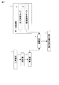
図1は、本実施形態に係る電池寿命推定装置の機能構成を示すブロック図である。
[Device configuration]
FIG. 1 is a block diagram showing a functional configuration of the battery life estimation apparatus according to the present embodiment.
図1に示す電池寿命推定装置は、1つまたは複数の電池セルを含む二次電池1の電圧・電流・温度等を測定する測定部2、推算部3、データ格納部4、演算部5、および残存寿命算出部6を有する。推算部3は、測定部2の測定データをもとに現時点の電池特性(劣化状態)を推算する。データ格納部4は、電池電圧と温度に対する劣化定数の分布を示す劣化特性マップ41と、電池の使用環境における温度時間分布、電流値時間分布及び充放電範囲を含む使用条件データ42とを格納する。演算部5は、データ格納部4に格納される使用条件データ42と劣化特性マップ41とに基づいて、電池特性の劣化量を推定する。残存寿命算出部6は、設定された使用条件データに対し電池の寿命の終了条件に達するまでの残存寿命を算出する。
The battery life estimation apparatus shown in FIG. 1 includes a
[劣化特性マップ41の作成]
電極としての劣化挙動は、上記3つの副反応の効果の和で表される。また電池としての劣化速度は正極と負極の和で表される。しかしながら、電池特性の劣化速度が3つの反応の和となるわけではない。電解液分解による劣化反応では生成物の被膜などの影響により電池の容量低下や内部抵抗上昇が進み、活物質劣化反応によってもやはり活物質の減少や不活性化により電池の容量低下や内部抵抗上昇が進む。また、活物質によって容量低下は起るが内部抵抗は上昇しないものや、その逆のものもある。そのため、容量低下、内部抵抗増加などの個別の電池特性の劣化速度式は各反応の和とはならない。同時に電池特性の変化の観察から個別の反応の反応速度を個別に測定することも困難である。
[Creation of deterioration characteristic map 41]
The deterioration behavior as an electrode is represented by the sum of the effects of the three side reactions. Moreover, the deterioration rate as a battery is represented by the sum of a positive electrode and a negative electrode. However, the deterioration rate of battery characteristics is not the sum of the three reactions. In the degradation reaction due to decomposition of the electrolyte, the battery capacity and internal resistance increase due to the effect of the product coating, etc., and the active material degradation reaction also decreases the battery capacity and increases internal resistance due to the decrease and inactivation of the active material. Advances. There are also active materials that cause a decrease in capacity but do not increase internal resistance, and vice versa. Therefore, the deterioration rate formulas for individual battery characteristics such as capacity reduction and internal resistance increase are not sums of reactions. At the same time, it is difficult to individually measure the reaction rate of individual reactions from observation of changes in battery characteristics.
従って、本実施形態に係る劣化特性マップ41は、電池内の各活物質の電位と温度に対する劣化速度を測定し、電位−温度平面に対する劣化定数の分布状態を作成することにより得ることが出来る。劣化速度の測定は、各活物質について実験セルを作成し、一定の電位に保持するフロート試験、または一定の電位に合わせた後に貯蔵する貯蔵試験を温度を変えて実施することで行うことができる。
Therefore, the deterioration
実験セルは、測定の対象とする活物質に対し、対極と参照極を金属リチウムとした三極セルあるいは過剰の正極材あるいは負極材を対極とした二極セルを用いることが好ましい。二極セルにおいては対極に用いる正極材および負極材は劣化の小さい材料が好ましく、具体的には正極材としてはリチウムリン酸鉄、負極材としてはチタン酸リチウムなどが挙げられる。特にこれらの材料では使用できる電解液の制約も少ないことがさらに利点として挙げられる。 As the experimental cell, it is preferable to use a triode cell having a counter electrode and a reference electrode as metallic lithium or a bipolar cell having an excess positive electrode material or negative electrode material as a counter electrode for the active material to be measured. In a bipolar cell, the positive electrode material and the negative electrode material used for the counter electrode are preferably materials with little deterioration. Specifically, examples of the positive electrode material include lithium iron phosphate, and examples of the negative electrode material include lithium titanate. In particular, these materials have a further advantage that there are few restrictions on the electrolyte solution that can be used.
劣化試験は、一定電位を強制的に保持するフロート試験と一定電位に合わせた後に放置する貯蔵試験を用いることが出来る。電位を開放状態では保持しにくい過充電領域および過放電領域はフロート試験による劣化速度測定が好ましい。電池が充放電で使用される範囲の電位についてはフロート試験および貯蔵試験のどちらを用いてもよい。また、劣化速度特性測定を行う電位の範囲はセルの使用範囲に該当する範囲に加え若干の広い範囲とすることが好ましい。フロート試験または貯蔵試験の試験期間は、1週間から4週間程度が好ましく、この間は実験セルの温度を恒温槽等により一定に保つ必要がある。試験温度は少なくとも3点以上で行う必要があり、25℃から65℃の範囲で設定されることが好ましい。さらに各温度条件に対して同じ電位条件のセルを試験する必要がある。 As the deterioration test, a float test that forcibly holds a constant potential and a storage test that is allowed to stand after being set to a constant potential can be used. For overcharge regions and overdischarge regions that are difficult to hold in an open state, it is preferable to measure the deterioration rate by a float test. Either the float test or the storage test may be used for the potential in the range where the battery is used for charging and discharging. Further, it is preferable that the potential range for measuring the degradation rate characteristic is a slightly wide range in addition to the range corresponding to the use range of the cell. The test period of the float test or the storage test is preferably about 1 to 4 weeks. During this period, it is necessary to keep the temperature of the experimental cell constant by a thermostat or the like. The test temperature must be at least 3 points and is preferably set in the range of 25 ° C to 65 ° C. Furthermore, it is necessary to test a cell having the same potential condition for each temperature condition.
このような条件で劣化試験を行うことで、同じ電位状態の活物質について、3点以上の温度でアレニウスプロットを行い、活性化エネルギーを算出することが出来る。電位条件は劣化特性マップをより正確なものとするために4点以上のより多くの条件で行うことが好ましい。試験期間終了ごとに基準温度、例えば25℃において容量値、内部抵抗値などを測定し、貯蔵期間に対しての劣化の傾き、すなわち劣化速度を評価する。この際、劣化挙動を記述する式として、ルート則、一次反応式、比例式、その他の反応式のうち測定された劣化挙動と一致するものを用いることが出来る。 By performing the deterioration test under such conditions, the activation energy can be calculated by performing an Arrhenius plot at three or more temperatures for the active material in the same potential state. In order to make the deterioration characteristic map more accurate, the potential condition is preferably performed under more conditions of 4 points or more. At the end of the test period, the capacity value, the internal resistance value, etc. are measured at a reference temperature, for example, 25 ° C., and the slope of deterioration with respect to the storage period, that is, the deterioration rate is evaluated. At this time, as a formula describing the degradation behavior, a route law, a primary reaction formula, a proportional formula, or any other reaction formula that matches the measured degradation behavior can be used.
また、上記では活物質の劣化特性を測定する方法について説明したが、より簡便な方法として実際のセルによるフロート試験または貯蔵試験より劣化特性マップを作成することもできる。温度を3点以上、電池電圧条件を4点以上としたフロートまたは貯蔵試験により実際のセルについて評価し、劣化特性マップを作成することができる。 In the above description, the method for measuring the degradation characteristic of the active material has been described. However, as a simpler method, a degradation characteristic map can be created by a float test or storage test using an actual cell. An actual cell can be evaluated by a float or storage test with a temperature of 3 points or more and a battery voltage condition of 4 points or more, and a deterioration characteristic map can be created.
このような劣化特性試験の結果より、本実施形態で用いられる電位(または電池電圧)−温度平面に対する劣化定数の分布状態が作成される。この分布おいては単純に測定結果がプロットされているだけではなく、アレニウスプロットより算出された活性化エネルギーを用いて温度に対して連続的に劣化定数が算出できる特性を有している。 From the result of the deterioration characteristic test, a distribution state of deterioration constants with respect to the potential (or battery voltage) -temperature plane used in the present embodiment is created. In this distribution, not only the measurement results are simply plotted, but also the deterioration constant can be calculated continuously with respect to the temperature using the activation energy calculated from the Arrhenius plot.
[使用条件データ42について]
本実施形態の二次電池の残存寿命推定方法では、電池の劣化量を推定する期間において電位−温度平面における滞在時間を計算し、上記の電位−温度平面に対する劣化定数の分布状態を参照して劣化量を計算する。従って、残存寿命推定において電池の使用条件および、現在時点での電池特性の2つのデータを必要とする。
[About use condition data 42]
In the method for estimating the remaining life of the secondary battery according to the present embodiment, the residence time on the potential-temperature plane is calculated during the period of estimating the amount of battery degradation, and the distribution state of the degradation constant with respect to the potential-temperature plane is referred to. Calculate the amount of degradation. Therefore, two data of the battery usage conditions and the current battery characteristics are required for the remaining life estimation.
電池の使用条件として必要となるのは、電池の使用環境における温度−時間分布と、電流値−時間分布と、充放電範囲の3つである。 Three conditions are required as the battery usage conditions: a temperature-time distribution, a current value-time distribution, and a charge / discharge range in the battery usage environment.
温度−時間分布としては、使用環境下で電池パック周囲の温度の分布を用いることが好ましいが、電池使用地域の気温の分布で代用、もしくは電池の運転条件と併せて電池温度を推算してもよい。 As the temperature-time distribution, it is preferable to use the temperature distribution around the battery pack under the usage environment. However, the temperature distribution in the battery usage area can be substituted, or the battery temperature can be estimated together with the battery operating conditions. Good.
電流値−時間分布については、それぞれのケースの実際の使用を完全に網羅したデータである必要は無く、デバイスまたは車両等で想定されている平均的な使用条件における電流値−時間分布で問題はない。電流分布野の中では放電、充電、休止を区別して表す必要があり、例えば放電電流値を負の値、充電電流値を正の値、休止状態を電流値ゼロとしてカウントすることができる。また、電流値−時間分布の情報を得ることが困難な場合には、機器の電力値−時間分布から電池の電流値−時間分布を算出して代用することもできる。 The current value-time distribution does not need to be data that completely covers the actual use of each case, and there is a problem with the current value-time distribution under the average usage conditions assumed for devices or vehicles. Absent. In the current distribution field, it is necessary to distinguish between discharge, charge, and rest. For example, the discharge current value can be counted as a negative value, the charge current value as a positive value, and the rest state can be counted as a current value zero. Further, when it is difficult to obtain information on the current value-time distribution, the battery current value-time distribution can be calculated from the power value-time distribution of the device and used instead.
電池の充放電範囲(電池使用SOC範囲)は、満充電条件とフル放電条件が必要である。さらに機器の電池制御において安全対策や劣化低減のために充電、放電を制限するような制御を行っていればその条件についても計算に加えることが、より正確な滞在時間の計算および寿命の推定のために好ましい。このような電池制御の例としては、電池温度により充電終了SOCを下げたり、また予期しない電池切れを防ぐために放電を電池能力より高い電圧で終了する等の方法がある。 The charge / discharge range (battery use SOC range) of the battery requires full charge conditions and full discharge conditions. In addition, if the battery control of equipment is controlled to limit charging and discharging for safety measures and reduction of deterioration, the conditions can also be added to the calculation. Therefore, it is preferable. Examples of such battery control include a method of lowering the charge termination SOC depending on the battery temperature, or terminating the discharge at a voltage higher than the battery capacity in order to prevent unexpected battery exhaustion.
[推算部3について]
現時点の電池特性の評価については、一般的に知られている電池特性の測定方法を用いることが出来る。具体的には、実際に電流を流して電池容量の測定を行う充放電試験や主に内部抵抗値の測定を行う電流休止法や交流インピーダンス測定などの電気化学的測定を組み合わせて行うことが出来る。さらに、特許文献1に開示されるような充放電曲線を解析して簡易的に電池特性を推定する方法を用いると時間や手間をかけずに必要な評価を行うことができ、測定精度的には直接測定には劣るものの有用な方法である。また、前述のような簡易測定手法は特別な測定機器が不要であるためユーザーが自分で特性評価を行えるという点からも、ユーザによる自力での電池評価・寿命予測を可能とするという観点から重要である。
[About the estimation unit 3]
For the evaluation of the current battery characteristics, a generally known battery characteristic measurement method can be used. Specifically, it is possible to perform a combination of electrochemical measurements such as a charge / discharge test that measures the battery capacity by actually passing a current, a current pause method that measures mainly the internal resistance, and an AC impedance measurement. . Furthermore, if the method of estimating a battery characteristic simply by analyzing a charge / discharge curve as disclosed in
[演算部5について]
次に、本実施形態の電池の残寿命の推定方法について説明する。図2に演算部5の処理手順について図示する。
[Calculation unit 5]
Next, a method for estimating the remaining battery life of this embodiment will be described. FIG. 2 illustrates a processing procedure of the
(ステップS1:滞在時間データ算出)
演算部5は、まず初めに使用条件データ42および現時点の電池特性データをもとに電位−温度平面における滞在時間の積算を行う。使用条件データの電池使用充放電範囲より、電池使用範囲におけるOCV(Open Circuit Voltage)曲線を作成する。評価時点で測定された電池特性より内部抵抗値を求め、温度分布と電流分布とから電位−温度平面での滞在時間分布を算出する。温度および電流の分布は相互に等価に分布しているものとし、電池の電位は電流値と内部抵抗の掛け算により計算される。
(Step S1: Time spent data calculation)
The
この際、内部抵抗値の温度変化を計算の中で考慮する必要がある。低温下では内部抵抗が上昇し大きな過電圧となり、また高温化では内部抵抗は低下し過電圧は小さくなるため、特に大電流での使用時には過電圧を過大または過少に見積もることとなる。特に、高温領域での電位の計算値の誤差により生じる劣化量の差は大きいため、内部抵抗は温度に関連付けて補正する必要がある。内部抵抗の温度補正は、初期状態の電池での内部抵抗値の温度による変化率を用いて簡易的に行うことができる。 At this time, it is necessary to consider the temperature change of the internal resistance value in the calculation. At low temperatures, the internal resistance increases and becomes a large overvoltage. At high temperatures, the internal resistance decreases and the overvoltage becomes small. Therefore, the overvoltage is estimated to be too large or too small particularly when used at a large current. In particular, since the difference in the amount of deterioration caused by an error in the calculated potential value in the high temperature region is large, the internal resistance needs to be corrected in association with the temperature. The temperature correction of the internal resistance can be easily performed using the rate of change of the internal resistance value with temperature in the battery in the initial state.
より高精度な方法として、内部抵抗を構成する抵抗成分をそれぞれ測定し、それぞれの内部抵抗温度依存性に従い温度補正を行って合算しても良い。例えば、電池の一定条件での充放電時の充放電曲線(電池電圧−時間、温度データ)より、各活物質の開回路電位−充電量データを参照し、電池の容量、内部抵抗および正負極の各活物質の劣化を評価できる。この際、各活物質の抵抗成分−充電量データを参照することで内部抵抗の各成分を分離評価することが可能である。内部抵抗の主な成分としては、オーミック抵抗、反応抵抗、拡散抵抗の3つが挙げられれる。この方法は、充放電曲線の解析による電池容量、内部抵抗成分の推定法方法を含んでおり、本実施形態の電池の残寿命の推定方法に親和性が高い。 As a more accurate method, the resistance components constituting the internal resistance may be measured, and temperature correction may be performed according to the internal resistance temperature dependence, and the sum may be added. For example, referring to the open circuit potential-charge amount data of each active material from the charge / discharge curve (battery voltage-time, temperature data) at the time of charge / discharge under a certain condition of the battery, the battery capacity, internal resistance and positive and negative electrodes The deterioration of each active material can be evaluated. At this time, it is possible to separate and evaluate each component of the internal resistance by referring to the resistance component-charge amount data of each active material. There are three main components of internal resistance: ohmic resistance, reaction resistance, and diffusion resistance. This method includes a method for estimating the battery capacity and the internal resistance component based on the analysis of the charge / discharge curve, and is highly compatible with the method for estimating the remaining battery life of this embodiment.
(ステップS2:劣化定数算出)
演算部5は、上記のように作成された電位−温度平面における滞在時間の積算に対し、少なくとも内部抵抗値および容量を含む電池の各特性についての電位−温度平面における劣化特性マップを参照し、上記の電位−温度平面に対する劣化定数の分布状態を算出する。
(Step S2: Deterioration constant calculation)
The
(ステップS3:劣化量算出)
演算部5は、上記の電位−温度平面に対する劣化定数の分布状態を参照して、平面全体の積算量として各特性の劣化量を推算する。
(Step S3: Calculation of deterioration amount)
The
本実施形態の電池寿命推定方法においては、電池特性のうち内部抵抗の計算は非常に重要な要素となる。電流印加時の電池の電位は内部抵抗との掛け算で算出され、全ての特性の劣化量の推定に影響するためである。さらに推算精度を向上する方法として、電池の劣化の進行により内部抵抗が上昇したことにより、さらに電流印加時の過電圧が大きくなり劣化を加速する効果を加える再帰計算を行うことができる。このような内部抵抗の増加がさらに劣化速度を上昇する効果が顕著となるのは、1つは電池のレート特性に対して電流値が大きく過電圧が非常に大きい場合、もう一つは電池使用範囲での電位に対する劣化速度の変化の傾きが大きい場合である。このような2つの条件が重なるケースでは電池の内部抵抗に関しては再帰計算を行い電位−温度の滞在時間を算出することが好ましい。 In the battery life estimation method of this embodiment, calculation of internal resistance is a very important factor among battery characteristics. This is because the potential of the battery at the time of current application is calculated by multiplication with the internal resistance and affects the estimation of the deterioration amount of all characteristics. Further, as a method for improving the estimation accuracy, recursive calculation can be performed to add an effect of accelerating the deterioration due to an increase in overvoltage at the time of current application due to an increase in internal resistance due to the progress of battery deterioration. The effect of increasing the internal resistance further increases the deterioration rate. One is when the current value is large and the overvoltage is very large with respect to the rate characteristics of the battery. This is a case where the gradient of the change in the deterioration rate with respect to the potential is large. In the case where these two conditions overlap, it is preferable to calculate the dwell time of the potential-temperature by performing recursive calculation regarding the internal resistance of the battery.
セル温度分布に関しても同様であり、電池のレート特性および電池パックの放熱能力に対し、大きな電流値で連続充放電を行うようなケースでは、内部抵抗の増加によるジュール熱の増大で、電池の温度分布は予測をする期間の間で上昇してしまうため、再帰計算を行うことが好ましい。数年以上の長期にわたる予測においても期間を数段階に区切って計算を行うことで精度を大幅に向上することができる。また、季節等による明確な環境温度変化がある場合にも、期間を区切って順次計算を行い劣化量を積算することがより精度よく推算を行うために有効である。再帰計算または期間分割による計算を行う場合には、電池特性のうち内部抵抗についての計算を初めに行い、その結果による過電圧シフトおよび温度上昇の効果を反映した電位−温度の滞在時間を算出し各特性の劣化特性マップを参照して劣化量を推定する。 The same applies to the cell temperature distribution. In the case where continuous charge / discharge is performed at a large current value with respect to the rate characteristics of the battery and the heat dissipation capacity of the battery pack, the temperature of the battery increases due to an increase in Joule heat due to an increase in internal resistance. Since the distribution increases during the prediction period, it is preferable to perform a recursive calculation. Even in the prediction over a long period of several years or more, the accuracy can be greatly improved by performing the calculation by dividing the period into several stages. In addition, even when there is a clear environmental temperature change due to the season or the like, it is effective in order to estimate more accurately by sequentially calculating by dividing the period and integrating the deterioration amount. When calculating by recursive calculation or period division, the internal resistance of the battery characteristics is calculated first, and the potential-temperature residence time reflecting the effect of overvoltage shift and temperature rise is calculated. A deterioration amount is estimated with reference to a characteristic deterioration characteristic map.
また、本実施形態の方法では、滞在SOCの偏りは考慮されておらず全て等価としているが、推算の目的を残り寿命の算出として劣化定数が急上昇する領域へ電池が滞在する時間の概算を行っているためである。特定のSOC付近での充放電あるいは貯蔵が多い等の条件を加えることで、劣化過程での挙動を含めたより精度の高い推算を行うことができる。 Further, in the method of this embodiment, the bias of stay SOC is not taken into consideration and all are equivalent. However, the purpose of the estimation is to calculate the remaining life, and to estimate the time that the battery stays in the region where the deterioration constant rapidly increases. This is because. By adding conditions such as charging / discharging or storage near a specific SOC, it is possible to perform more accurate estimation including behavior in the deterioration process.
[残存寿命算出部6について]
実際の電池の使用における電池特性の劣化挙動においては、ある期間はルート則あるいは一次反応則等に従った一定の劣化傾向で劣化が進み、最終的には電池特性が急低下する劣化加速が起こり寿命を終了する。本実施形態では、現時点からの期間を自由に設定することができ、残存寿命算出部6は、例えばある特性値が下限値を下回ったら寿命の終わりという条件に、現在の使用を続けた場合の残り期間を求めることができる。また逆に、特定の使用期間を確保するために使用条件をどのような条件にすればよいかを推算することもできる。
[Residual Life Calculation Unit 6]
In the deterioration behavior of battery characteristics in actual battery use, the deterioration progresses with a certain deterioration tendency according to the root rule or the first-order reaction law for a certain period, and eventually the deterioration of the battery characteristics suddenly decreases. End the life. In the present embodiment, the period from the present time can be set freely, and the remaining
また、別の方法として電池をより長期間活用するための使用条件の調整がある。使用中の電池の寿命の最後に起こる急激な劣化加速の段階では、内部抵抗の増加による過電圧の上昇および電池温度の上昇が進行していると推測される。この急劣化を避けて電池を使用するために、本実施形態における電池の電位−温度の滞在時間データをもとに使用条件の調整を行うことが可能である。すなわち内部抵抗の増加に応じて、使用により高温・高電圧側の劣化速度が大きい領域に電池が入る割合を減らすように使用条件のうち温度条件または電流条件を緩和することが考えられる。例えば、機器または車両を温度の低い地域で使用したり、またはより入出力値の低い機器での利用に電池をリユースしたりということが考えられる。 As another method, there is adjustment of usage conditions for utilizing the battery for a longer period of time. At the stage of rapid deterioration acceleration that occurs at the end of the life of the battery in use, it is presumed that an increase in overvoltage and an increase in battery temperature due to an increase in internal resistance are in progress. In order to avoid the sudden deterioration and use the battery, it is possible to adjust the use condition based on the stay time data of the potential-temperature of the battery in this embodiment. That is, it can be considered that the temperature condition or the current condition is relaxed among the use conditions so as to reduce the ratio of the battery entering the region where the deterioration rate on the high temperature / high voltage side is large due to use as the internal resistance increases. For example, it can be considered that the device or the vehicle is used in a region where the temperature is low, or the battery is reused for use in a device having a lower input / output value.
このような寿命推定においては、ある程度寿命に余力を残した段階に電池寿命の終わりを設定することが望ましく、劣化加速が顕在化する前に急劣化の兆候を検出する必要がある。例えば、残存寿命算出部6は、劣化速度データにおいて劣化速度がある設定値以上となる領域に入る割合が単位時間に対してある割合を超えたら寿命の終わりとすることができる。また、これは電池の初期状態から本実施形態の寿命推定を行ってきたことが前提となるが、電池の全寿命を通して劣化速度がある設定値以上となる領域に入る積算時間が一定以上となったら寿命の終わりとすることもできる。
In such life estimation, it is desirable to set the end of the battery life at a stage where there is some remaining capacity in the life, and it is necessary to detect signs of rapid deterioration before acceleration of deterioration becomes apparent. For example, the remaining
[実施例の説明]
本実施形態に係る二次電池の残存寿命推定方法について、正極をコバルト酸リチウム、負極をチタン酸リチウムとした電池を例として説明する。
[Description of Examples]
The method for estimating the remaining life of the secondary battery according to this embodiment will be described by taking as an example a battery in which the positive electrode is lithium cobaltate and the negative electrode is lithium titanate.
劣化特性マップは、電池の貯蔵試験およびフロート試験の結果を集計し作成した。試験の詳細な条件は、以下に示すとおりである。貯蔵試験として、電池OCVが、2.33V、2.35V、2.44V、2.70Vに調整した電池それぞれに対し、25℃、35℃、45℃、55℃の温度での試験を行った。また、フロート試験として電池電圧2.8V、1.5Vに保持する試験を25℃、35℃、45℃の環境下で行った。試験は最初の4週間は1週間毎に、それ以降は3週間毎に25℃環境下で0.2C容量およびSOC10%〜90%のSOC10%毎に電流値5Cでの10s抵抗を測定した。 The deterioration characteristic map was created by collecting the results of battery storage tests and float tests. The detailed conditions of the test are as shown below. As a storage test, the batteries OCV were adjusted to 2.33V, 2.35V, 2.44V, and 2.70V, respectively, and tests were conducted at temperatures of 25 ° C, 35 ° C, 45 ° C, and 55 ° C. . Moreover, the test which hold | maintains to battery voltage 2.8V and 1.5V as a float test was done in the environment of 25 degreeC, 35 degreeC, and 45 degreeC. In the test, the 10s resistance at a current value of 5C was measured every 10% of SOC of 0.2C capacity and SOC of 10% to 90% in a 25C environment every week for the first 4 weeks and thereafter every 3 weeks.
図3Aおよび図3Bは、この寿命試験の結果より、内部抵抗値の平均値および電池容量の劣化速度係数の分布を示す劣化特性マップである。図3Aにおいては、X軸にセル電圧、Y軸に温度、Z軸に劣化速度として内部抵抗増加速度定数を表している。図3Bにおいては、X軸にセル電圧、Y軸に温度、Z軸に劣化速度として容量減少速度定数を表している。劣化速度式については内部抵抗値についてはルート則、容量低下については一次反応則を採用している。 3A and 3B are deterioration characteristic maps showing the distribution of the average value of the internal resistance value and the deterioration rate coefficient of the battery capacity based on the results of the life test. In FIG. 3A, the cell resistance is represented on the X axis, the temperature is represented on the Y axis, and the internal resistance increasing rate constant is represented on the Z axis. In FIG. 3B, the capacity reduction rate constant is represented by the cell voltage on the X axis, the temperature on the Y axis, and the deterioration rate on the Z axis. For the degradation rate equation, the root law is adopted for the internal resistance value, and the first order reaction law is adopted for the capacity reduction.
使用条件は、推定原理の確認のため単純な条件として、25℃および45℃環境下における5C定電流充放電サイクルの2つを例として挙げる。この場合、電流値−時間分布条件としては共通で−5Cで50%(放電)、+5C(充電)で50%の条件となり、温度−時間分布条件はそれぞれ25℃および45℃で一定となる。この条件をもとに初期状態から30日ごとに期間を区切り、内部抵抗と温度を更新しながら内部抵抗および容量の劣化量を推定した結果を実測値とともに図4A及び図4Bに示す。図4Aは、25℃5Cサイクルにおける内部抵抗および容量の劣化量の推定結果を示す図である。図4Bは、45℃5Cサイクルにおける内部抵抗および容量の劣化量の推定結果を示す図である。実測値と推算値は概ね良い一致を示し、図4Bに示す45℃サイクルにおいては劣化が加速する時点についても実測値と一致する。 As for the use conditions, two conditions of a 5C constant current charge / discharge cycle under the environment of 25 ° C. and 45 ° C. are given as examples for confirming the estimation principle. In this case, the current value-time distribution condition is commonly 50% at -5C (discharge) and 50% at + 5C (charge), and the temperature-time distribution condition is constant at 25 ° C. and 45 ° C., respectively. 4A and 4B show the results of estimating the amount of deterioration of the internal resistance and the capacity while updating the internal resistance and temperature while dividing the period every 30 days from the initial state based on this condition, together with the actual measurement values. FIG. 4A is a diagram showing an estimation result of the deterioration amount of the internal resistance and the capacity in a cycle of 25 ° C. and 5C. FIG. 4B is a diagram showing an estimation result of the amount of deterioration of internal resistance and capacity in a 45 ° C. and 5C cycle. The actually measured value and the estimated value are in good agreement with each other, and at the 45 ° C. cycle shown in FIG.
なお、ルート則、一次反応則における劣化量の推算では、図5に示すように使用期間をΔtで区切った際の平均劣化速度定数a1,a2,…と、その区間開始時点までの劣化量から算出される時間初期値R0,R1,…とを用いて劣化量R2を推算する。ルート則や一次反応則の速度式では時間Δtだけでは劣化量か決まらずΔtの開始時点(図5中におけるt1)が必要となる。t1の値は前区間までの劣化量R1に対して劣化量の算出を行う区間の劣化定数a2を用いて図5中の囲み内の式のように算出される。 In the estimation of the deterioration amount in the root rule and the primary reaction rule, as shown in FIG. 5, the average deterioration rate constants a 1 , a 2 ,... The deterioration amount R 2 is estimated using the initial time values R 0 , R 1 ,... Calculated from the amounts. In the velocity equation of the route rule or the first-order reaction rule, the deterioration amount is not determined only by the time Δt, and the starting point of Δt (t 1 in FIG. 5) is required. The value of t 1 is calculated as in the equation in the box in FIG. 5 using the deterioration constant a 2 of the section in which the deterioration amount is calculated for the deterioration amount R 1 up to the previous section.
さらに同条件の推算において、約3ヶ月経過時点を出発点として推算を行った結果を図6A,図6Bに示す。図6Aは、25℃5Cサイクルにおける内部抵抗および容量の劣化量の推定結果を示す図である。図6Bは、45℃5Cサイクルにおける内部抵抗および容量の劣化量の推定結果を示す図である。図4A,図4Bにおいて示した結果と同様に実測の挙動と良い一致を示しており、使用途中からの推算でも有効であることが確認できる。 Furthermore, in the estimation under the same conditions, the results of estimation starting from the point of about 3 months elapsed are shown in FIGS. 6A and 6B. FIG. 6A is a diagram showing estimation results of internal resistance and capacity deterioration amounts at 25 ° C. and 5 C cycles. FIG. 6B is a diagram showing an estimation result of the degradation amount of the internal resistance and the capacity in a 45 ° C. and 5C cycle. Similar to the results shown in FIG. 4A and FIG. 4B, the measured behavior is in good agreement with the results, and it can be confirmed that the estimation from the middle of use is also effective.
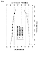
次に、図7Aおよび図7B示す使用条件について寿命推定を行った結果を図8に示す。図7Aに示す電流値−時間分布、および図7Bに示す温度−時間分布について、期間を3ヶ月ごとに区切り、内部抵抗を順次更新して推算を行っている。図8に示すとおり寿命は5年以上の長期にわたるため実測値は取得できていないが、8年強の時点で特性が急落し始め電池使用が不可能になるであろうことが予測できる。 Next, FIG. 8 shows the result of life estimation under the use conditions shown in FIGS. 7A and 7B. With respect to the current value-time distribution shown in FIG. 7A and the temperature-time distribution shown in FIG. 7B, the period is divided every three months, and the internal resistance is sequentially updated for estimation. As shown in FIG. 8, the measured value cannot be obtained because the life span is longer than 5 years. However, it can be predicted that the characteristics will begin to drop sharply at the time of just over 8 years and the battery will not be usable.
そこで、7年で使用条件を、図9Aに示す電流値−時間分布、および図9Bに示す温度−時間分布に変更する場合の推定結果を図10に示す。この場合の予測では、さらに推算上は13年の時点まで電池を使用できる可能性が見出せる。本実施形態の電池残存寿命の推算方法によれば、図10に示すように、電池使用条件の調整により電池の有効利用にも寄与できるものと考えられる。 Therefore, FIG. 10 shows an estimation result when the usage condition is changed to the current value-time distribution shown in FIG. 9A and the temperature-time distribution shown in FIG. 9B in 7 years. In the prediction in this case, it is possible to find a possibility that the battery can be used until the time of 13 years. According to the method for estimating the remaining battery life of the present embodiment, as shown in FIG. 10, it is considered that adjustment of the battery use conditions can contribute to effective use of the battery.
なお、この発明は、上記実施形態そのままに限定されるものではなく、実施段階ではその要旨を逸脱しない範囲で構成要素を変形して具体化できる。また、上記実施形態に開示されている複数の構成要素の適宜な組み合せにより種々の発明を形成できる。例えば、実施形態に示される全構成要素から幾つかの構成要素を削除してもよい。さらに、異なる実施形態に亘る構成要素を適宜組み合せてもよい。 Note that the present invention is not limited to the above-described embodiment as it is, and can be embodied by modifying the constituent elements without departing from the scope of the invention in the implementation stage. Further, various inventions can be formed by appropriately combining a plurality of constituent elements disclosed in the embodiment. For example, some components may be deleted from all the components shown in the embodiment. Furthermore, you may combine suitably the component covering different embodiment.
1…二次電池、2…測定部、3…推算部、4…データ格納部、41…劣化特性マップ、42…使用条件データ、5…演算部、6…残存寿命算出部。
DESCRIPTION OF
Claims (9)
推定期間における温度時間分布及び電流値時間分布を含む使用条件データと、電池電圧と温度に対する劣化定数の分布を示す劣化特性マップとを格納することと、
前記現時点の電池特性データと使用条件データとに基づいて前記劣化特性マップにおける電池電圧−温度平面の滞在時間を積算することにより劣化量を推定することと
を有する電池寿命推定方法。 Calculating the current battery characteristic data including at least the internal resistance value for the secondary battery;
Storing usage condition data including a temperature time distribution and a current value time distribution in an estimation period, and a deterioration characteristic map indicating a distribution of deterioration constants with respect to battery voltage and temperature;
A battery life estimation method comprising: estimating a deterioration amount by integrating a stay time of a battery voltage-temperature plane in the deterioration characteristic map based on the current battery characteristic data and use condition data.
推定期間における温度時間分布及び電流値時間分布を含む使用条件データと、電池電圧と温度に対する劣化定数の分布を示す劣化特性マップとを格納する格納部と、
前記現時点の電池特性データと使用条件データとに基づいて前記劣化特性マップにおける電池電圧−温度平面の滞在時間を積算することにより劣化量を推定する演算部と
を具備する電池寿命推定装置。 An estimation unit for calculating current battery characteristic data including at least an internal resistance value for the secondary battery;
A storage unit for storing usage condition data including a temperature time distribution and a current value time distribution in an estimation period, and a deterioration characteristic map indicating a distribution of deterioration constants with respect to battery voltage and temperature;
A battery life estimation apparatus comprising: an arithmetic unit that estimates a deterioration amount by integrating a stay time of a battery voltage-temperature plane in the deterioration characteristic map based on the current battery characteristic data and use condition data.
Priority Applications (5)
| Application Number | Priority Date | Filing Date | Title |
|---|---|---|---|
| JP2013064912A JP2014190763A (en) | 2013-03-26 | 2013-03-26 | Battery lifetime estimation method and battery lifetime estimation device |
| EP14775842.9A EP2980595A4 (en) | 2013-03-26 | 2014-03-19 | Battery life estimation method and battery life estimation device |
| CN201480017818.2A CN105102999A (en) | 2013-03-26 | 2014-03-19 | Battery life estimation method and battery life estimation device |
| PCT/JP2014/057499 WO2014156869A1 (en) | 2013-03-26 | 2014-03-19 | Battery life estimation method and battery life estimation device |
| US14/862,393 US20160011274A1 (en) | 2013-03-26 | 2015-09-23 | Battery life estimation method and battery life estimation apparatus |
Applications Claiming Priority (1)
| Application Number | Priority Date | Filing Date | Title |
|---|---|---|---|
| JP2013064912A JP2014190763A (en) | 2013-03-26 | 2013-03-26 | Battery lifetime estimation method and battery lifetime estimation device |
Publications (1)
| Publication Number | Publication Date |
|---|---|
| JP2014190763A true JP2014190763A (en) | 2014-10-06 |
Family
ID=51623848
Family Applications (1)
| Application Number | Title | Priority Date | Filing Date |
|---|---|---|---|
| JP2013064912A Pending JP2014190763A (en) | 2013-03-26 | 2013-03-26 | Battery lifetime estimation method and battery lifetime estimation device |
Country Status (5)
| Country | Link |
|---|---|
| US (1) | US20160011274A1 (en) |
| EP (1) | EP2980595A4 (en) |
| JP (1) | JP2014190763A (en) |
| CN (1) | CN105102999A (en) |
| WO (1) | WO2014156869A1 (en) |
Cited By (20)
| Publication number | Priority date | Publication date | Assignee | Title |
|---|---|---|---|---|
| CN104459556A (en) * | 2014-12-03 | 2015-03-25 | 重庆长安汽车股份有限公司 | Battery system fault diagnosis method and device |
| JP2016080477A (en) * | 2014-10-15 | 2016-05-16 | 株式会社Gsユアサ | Performance deterioration detector of power storage element, performance deterioration detection method, and power storage system |
| EP3038229A1 (en) | 2014-12-26 | 2016-06-29 | Kabushiki Kaisha Toshiba | Storage battery, storage-battery evaluating device, and storage-battery evaluating method |
| JP2016167368A (en) * | 2015-03-09 | 2016-09-15 | トヨタ自動車株式会社 | Control device for secondary battery |
| JP2016197955A (en) * | 2015-04-03 | 2016-11-24 | プライムアースEvエナジー株式会社 | Battery controller, battery control method and lower limit voltage determination method |
| WO2017022037A1 (en) * | 2015-07-31 | 2017-02-09 | 株式会社 東芝 | Storage battery evaluating device, power storage system and storage battery evaluating method |
| WO2018003210A1 (en) * | 2016-06-28 | 2018-01-04 | 株式会社日立製作所 | Secondary cell control system and secondary cell control method |
| JPWO2017002292A1 (en) * | 2015-06-30 | 2018-04-19 | 株式会社村田製作所 | Power storage system, controller and storage battery charging / discharging method |
| CN109596986A (en) * | 2018-12-29 | 2019-04-09 | 蜂巢能源科技有限公司 | Power battery pack internal resistance estimation on line method and battery management system |
| US10274545B2 (en) | 2014-03-18 | 2019-04-30 | Kabushiki Kaisha Toshiba | Calculation apparatus and method for calculating relationship between charge amount and potential |
| US10338144B2 (en) | 2014-03-17 | 2019-07-02 | Kabushiki Kaisha Toshiba | Calculation apparatus and calculation method |
| JPWO2018062394A1 (en) * | 2016-09-29 | 2019-08-08 | 株式会社Gsユアサ | Storage device SOC estimation device, power storage device, and storage device SOC estimation method |
| JP2020139913A (en) * | 2019-03-01 | 2020-09-03 | トヨタ自動車株式会社 | Secondary battery abnormality determination method |
| JP2020180820A (en) * | 2019-04-24 | 2020-11-05 | 株式会社日立製作所 | Battery evaluation system, battery evaluation method, and program |
| US10871522B2 (en) | 2013-12-06 | 2020-12-22 | Kabushiki Kaisha Toshiba | Cell calculation apparatus and method for calculating an open-circuit voltage of a cell |
| WO2021044635A1 (en) | 2019-09-06 | 2021-03-11 | 株式会社 東芝 | Storage battery evaluation device, storage battery evaluation method and storage battery evaluation system |
| US11201486B2 (en) | 2019-09-17 | 2021-12-14 | Kabushiki Kaisha Toshiba | Battery control device, charge and discharge system, parking lot system, secondary battery reuse system, battery control method, and non-transitory storage medium |
| US11385293B2 (en) | 2018-09-12 | 2022-07-12 | Kabushiki Kaisha Toshiba | Battery state estimating apparatus, battery state estimating method, non-transitory computer readable medium, control circuit and power storage system |
| WO2023139684A1 (en) * | 2022-01-19 | 2023-07-27 | 株式会社日立ハイテク | Battery residual value management system and battery residual value management method |
| US11846681B2 (en) | 2019-04-26 | 2023-12-19 | Gs Yuasa International Ltd. | Estimation apparatus and estimation method |
Families Citing this family (28)
| Publication number | Priority date | Publication date | Assignee | Title |
|---|---|---|---|---|
| CN105122029A (en) * | 2013-04-22 | 2015-12-02 | 沃尔沃卡车集团 | Method for monitoring state of health of a vehicle system |
| US10261136B2 (en) * | 2014-07-01 | 2019-04-16 | Nissan Motor Co., Ltd. | Battery degradation degree estimation device and battery degradation degree estimation method |
| KR101619634B1 (en) * | 2014-11-06 | 2016-05-10 | 현대자동차주식회사 | System for estimating state of health using battery moedel parameter and method thereof |
| CN104678320B (en) * | 2015-03-16 | 2017-07-11 | 西北工业大学 | Electrokinetic cell service life supervision method based on internal resistance on-line testing |
| KR102468895B1 (en) * | 2015-07-21 | 2022-11-21 | 삼성전자주식회사 | Method and apparatus for estimating state of battery |
| JP6183446B2 (en) * | 2015-12-25 | 2017-08-23 | マツダ株式会社 | Lithium ion battery charge / discharge controller |
| US10985610B2 (en) | 2016-04-01 | 2021-04-20 | Enel X North America, Inc. | High speed control systems and methods for economical optimization of an electrical system |
| US20170286882A1 (en) | 2016-04-01 | 2017-10-05 | Demand Energy Networks, Inc. | Control systems and methods for economical optimization of an electrical system |
| JP6555212B2 (en) * | 2016-08-15 | 2019-08-07 | トヨタ自動車株式会社 | Battery pack manufacturing method |
| JP6883742B2 (en) * | 2016-09-16 | 2021-06-09 | パナソニックIpマネジメント株式会社 | Battery diagnostic methods, battery diagnostic programs, battery management devices, and power storage systems |
| KR20180085165A (en) * | 2017-01-18 | 2018-07-26 | 삼성전자주식회사 | Method and apparatus for managing battery |
| JP6804052B2 (en) * | 2017-03-31 | 2020-12-23 | 株式会社村田製作所 | Lithium ion secondary battery |
| US11300624B2 (en) | 2017-07-28 | 2022-04-12 | Northstar Battery Company, Llc | System for utilizing battery operating data |
| WO2019054020A1 (en) * | 2017-09-15 | 2019-03-21 | パナソニックIpマネジメント株式会社 | Battery management device, battery system, and battery management method |
| US11121552B2 (en) | 2018-07-02 | 2021-09-14 | Enel X North America, Inc. | Demand setpoint management in electrical system control and related systems, apparatuses, and methods |
| JP6973334B2 (en) * | 2018-08-30 | 2021-11-24 | トヨタ自動車株式会社 | Secondary battery deterioration state estimation method and secondary battery system |
| KR102351637B1 (en) * | 2018-09-12 | 2022-01-14 | 주식회사 엘지에너지솔루션 | Apparatus and method for managing battery |
| US10859986B2 (en) | 2018-12-28 | 2020-12-08 | Enel X North America, Inc. | Electrical system control for achieving long-term objectives, and related systems, apparatuses, and methods |
| CN111800535B (en) * | 2019-04-09 | 2021-07-20 | Oppo广东移动通信有限公司 | Terminal running state evaluation method and device, storage medium and electronic equipment |
| EP4004570A1 (en) * | 2019-07-24 | 2022-06-01 | Eco Stor AS | Method and device for predicting state of health and remaining lifetime for used electric vehicle batteries |
| CN110824361B (en) * | 2019-11-20 | 2022-07-26 | 中国船舶重工集团海装风电股份有限公司 | Method, device, equipment and medium for calculating residual life of super capacitor of wind turbine generator |
| CN110988717B (en) * | 2019-12-10 | 2022-03-25 | 惠州Tcl移动通信有限公司 | Battery detection method, storage medium and terminal device |
| JP7225153B2 (en) * | 2020-03-13 | 2023-02-20 | 株式会社東芝 | Charge/discharge control method, battery-equipped device, management system, charge/discharge control program, management method, management server, and management program |
| CN111665452B (en) * | 2020-06-30 | 2022-03-22 | 东风商用车有限公司 | Lithium ion storage battery monomer service life detection model |
| US11668756B2 (en) | 2020-09-25 | 2023-06-06 | Google Llc | Battery degradation monitoring system and methods |
| US11680918B2 (en) * | 2020-09-25 | 2023-06-20 | Google Llc | Thermal gradient battery monitoring system and methods |
| US11366173B2 (en) | 2020-11-06 | 2022-06-21 | Robert Bosch Gmbh | Method of determining lifetime of electrical and mechanical components |
| US11801768B2 (en) | 2021-05-05 | 2023-10-31 | Toyota Motor North America, Inc. | Transport battery health |
Citations (9)
| Publication number | Priority date | Publication date | Assignee | Title |
|---|---|---|---|---|
| JP2009080104A (en) * | 2007-09-07 | 2009-04-16 | Panasonic Corp | Secondary-battery life estimation apparatus and method |
| JP2010159661A (en) * | 2009-01-07 | 2010-07-22 | Shin Kobe Electric Mach Co Ltd | Storage battery control system for wind power generation and method for controlling the same |
| JP2011099691A (en) * | 2009-11-04 | 2011-05-19 | Honda Motor Co Ltd | Electric vehicle |
| JP2011142036A (en) * | 2010-01-08 | 2011-07-21 | Sanyo Electric Co Ltd | Battery control method and electronic equipment |
| JP2011257214A (en) * | 2010-06-08 | 2011-12-22 | Shin Kobe Electric Mach Co Ltd | Battery state estimating device and battery information notifying device |
| JP2012037464A (en) * | 2010-08-11 | 2012-02-23 | Shin Kobe Electric Mach Co Ltd | Lead storage battery for system using natural energy and lead storage battery system |
| JP2012135168A (en) * | 2010-12-24 | 2012-07-12 | Honda Motor Co Ltd | Electric vehicle |
| JP2012251806A (en) * | 2011-05-31 | 2012-12-20 | Toshiba Corp | Calculation method, calculation program, calculation system, and calculation device |
| JP2013019852A (en) * | 2011-07-13 | 2013-01-31 | Toyota Motor Corp | Device and method for estimating deterioration rate |
Family Cites Families (9)
| Publication number | Priority date | Publication date | Assignee | Title |
|---|---|---|---|---|
| JP4042475B2 (en) * | 2002-06-12 | 2008-02-06 | トヨタ自動車株式会社 | Battery deterioration degree calculating device and deterioration degree calculating method |
| EP1941289B1 (en) * | 2005-10-28 | 2010-12-22 | TEMIC Automotive Electric Motors GmbH | Method and device for determining the ageing of a battery |
| US7593823B2 (en) * | 2006-11-21 | 2009-09-22 | The Furukawa Electric Co., Ltd | Method and device for determining state of battery, and battery power supply system therewith |
| US8407018B2 (en) * | 2009-03-24 | 2013-03-26 | American Power Conversion Corporation | Battery life estimation |
| DE102009024422B4 (en) * | 2009-06-09 | 2017-08-03 | Continental Automotive Gmbh | Method for estimating the life of an energy storage device |
| JP5586219B2 (en) * | 2009-12-25 | 2014-09-10 | 株式会社東芝 | Diagnostic device, battery pack, and battery value index manufacturing method |
| DE102010031337A1 (en) * | 2010-07-14 | 2012-01-19 | Sb Limotive Company Ltd. | Method for determining the probable lifetime of at least one battery cell, battery having a plurality of battery cells and motor vehicle |
| JP5875037B2 (en) * | 2011-07-08 | 2016-03-02 | インターナショナル・ビジネス・マシーンズ・コーポレーションInternational Business Machines Corporation | Battery state prediction system, method and program |
| FR2980274B1 (en) * | 2011-09-15 | 2014-06-13 | Peugeot Citroen Automobiles Sa | METHOD FOR ESTIMATING AGING INDICATORS OF A TRACTION BATTERY OF AN ELECTRIC OR HYBRID MOTOR VEHICLE |
-
2013
- 2013-03-26 JP JP2013064912A patent/JP2014190763A/en active Pending
-
2014
- 2014-03-19 WO PCT/JP2014/057499 patent/WO2014156869A1/en active Application Filing
- 2014-03-19 CN CN201480017818.2A patent/CN105102999A/en active Pending
- 2014-03-19 EP EP14775842.9A patent/EP2980595A4/en not_active Withdrawn
-
2015
- 2015-09-23 US US14/862,393 patent/US20160011274A1/en not_active Abandoned
Patent Citations (9)
| Publication number | Priority date | Publication date | Assignee | Title |
|---|---|---|---|---|
| JP2009080104A (en) * | 2007-09-07 | 2009-04-16 | Panasonic Corp | Secondary-battery life estimation apparatus and method |
| JP2010159661A (en) * | 2009-01-07 | 2010-07-22 | Shin Kobe Electric Mach Co Ltd | Storage battery control system for wind power generation and method for controlling the same |
| JP2011099691A (en) * | 2009-11-04 | 2011-05-19 | Honda Motor Co Ltd | Electric vehicle |
| JP2011142036A (en) * | 2010-01-08 | 2011-07-21 | Sanyo Electric Co Ltd | Battery control method and electronic equipment |
| JP2011257214A (en) * | 2010-06-08 | 2011-12-22 | Shin Kobe Electric Mach Co Ltd | Battery state estimating device and battery information notifying device |
| JP2012037464A (en) * | 2010-08-11 | 2012-02-23 | Shin Kobe Electric Mach Co Ltd | Lead storage battery for system using natural energy and lead storage battery system |
| JP2012135168A (en) * | 2010-12-24 | 2012-07-12 | Honda Motor Co Ltd | Electric vehicle |
| JP2012251806A (en) * | 2011-05-31 | 2012-12-20 | Toshiba Corp | Calculation method, calculation program, calculation system, and calculation device |
| JP2013019852A (en) * | 2011-07-13 | 2013-01-31 | Toyota Motor Corp | Device and method for estimating deterioration rate |
Cited By (32)
| Publication number | Priority date | Publication date | Assignee | Title |
|---|---|---|---|---|
| US10871522B2 (en) | 2013-12-06 | 2020-12-22 | Kabushiki Kaisha Toshiba | Cell calculation apparatus and method for calculating an open-circuit voltage of a cell |
| US10338144B2 (en) | 2014-03-17 | 2019-07-02 | Kabushiki Kaisha Toshiba | Calculation apparatus and calculation method |
| US10274545B2 (en) | 2014-03-18 | 2019-04-30 | Kabushiki Kaisha Toshiba | Calculation apparatus and method for calculating relationship between charge amount and potential |
| JP2016080477A (en) * | 2014-10-15 | 2016-05-16 | 株式会社Gsユアサ | Performance deterioration detector of power storage element, performance deterioration detection method, and power storage system |
| CN104459556A (en) * | 2014-12-03 | 2015-03-25 | 重庆长安汽车股份有限公司 | Battery system fault diagnosis method and device |
| EP3038229A1 (en) | 2014-12-26 | 2016-06-29 | Kabushiki Kaisha Toshiba | Storage battery, storage-battery evaluating device, and storage-battery evaluating method |
| JP2016167368A (en) * | 2015-03-09 | 2016-09-15 | トヨタ自動車株式会社 | Control device for secondary battery |
| DE102016103807B4 (en) * | 2015-03-09 | 2020-09-17 | Toyota Jidosha Kabushiki Kaisha | A controller for a secondary battery that sets a lower limit SOC setting value that is lower than the preset lower limit SOC setting value and is higher than the SOC 0% |
| US9815383B2 (en) | 2015-03-09 | 2017-11-14 | Toyota Jidosha Kabushiki Kaisha | Controller for secondary battery |
| JP2016197955A (en) * | 2015-04-03 | 2016-11-24 | プライムアースEvエナジー株式会社 | Battery controller, battery control method and lower limit voltage determination method |
| US10283820B2 (en) | 2015-06-30 | 2019-05-07 | Murata Manufacturing Co., Ltd. | Electrical storage system, controller, and storage battery charging and discharging method |
| JPWO2017002292A1 (en) * | 2015-06-30 | 2018-04-19 | 株式会社村田製作所 | Power storage system, controller and storage battery charging / discharging method |
| US10372183B2 (en) | 2015-07-31 | 2019-08-06 | Kabushiki Kaisha Toshiba | Storage-battery evaluation device, energy storage system, and storage-battery evaluation method |
| JP2017194468A (en) * | 2015-07-31 | 2017-10-26 | 株式会社東芝 | Storage battery evaluation device, power storage system, storage battery evaluation method, and computer program |
| CN106796267A (en) * | 2015-07-31 | 2017-05-31 | 株式会社东芝 | Battery evaluating apparatus, accumulating system and battery evaluation method |
| CN106796267B (en) * | 2015-07-31 | 2020-06-23 | 株式会社东芝 | Storage battery evaluation device, storage battery system, and storage battery evaluation method |
| JP6134438B1 (en) * | 2015-07-31 | 2017-05-24 | 株式会社東芝 | Storage battery evaluation device, power storage system, and storage battery evaluation method |
| WO2017022037A1 (en) * | 2015-07-31 | 2017-02-09 | 株式会社 東芝 | Storage battery evaluating device, power storage system and storage battery evaluating method |
| WO2018003210A1 (en) * | 2016-06-28 | 2018-01-04 | 株式会社日立製作所 | Secondary cell control system and secondary cell control method |
| JPWO2018062394A1 (en) * | 2016-09-29 | 2019-08-08 | 株式会社Gsユアサ | Storage device SOC estimation device, power storage device, and storage device SOC estimation method |
| JP7172599B2 (en) | 2016-09-29 | 2022-11-16 | 株式会社Gsユアサ | SOC ESTIMATION DEVICE FOR ELECTRICAL STORAGE ELEMENT, ELECTRICAL STORAGE DEVICE, SOC ESTIMATION METHOD FOR ELECTRICAL STORAGE ELEMENT |
| US11385293B2 (en) | 2018-09-12 | 2022-07-12 | Kabushiki Kaisha Toshiba | Battery state estimating apparatus, battery state estimating method, non-transitory computer readable medium, control circuit and power storage system |
| CN109596986A (en) * | 2018-12-29 | 2019-04-09 | 蜂巢能源科技有限公司 | Power battery pack internal resistance estimation on line method and battery management system |
| JP7089677B2 (en) | 2019-03-01 | 2022-06-23 | トヨタ自動車株式会社 | Secondary battery abnormality judgment method |
| JP2020139913A (en) * | 2019-03-01 | 2020-09-03 | トヨタ自動車株式会社 | Secondary battery abnormality determination method |
| JP2020180820A (en) * | 2019-04-24 | 2020-11-05 | 株式会社日立製作所 | Battery evaluation system, battery evaluation method, and program |
| JP7300878B2 (en) | 2019-04-24 | 2023-06-30 | 株式会社日立製作所 | BATTERY EVALUATION SYSTEM, BATTERY EVALUATION METHOD AND PROGRAM |
| US11846681B2 (en) | 2019-04-26 | 2023-12-19 | Gs Yuasa International Ltd. | Estimation apparatus and estimation method |
| WO2021044635A1 (en) | 2019-09-06 | 2021-03-11 | 株式会社 東芝 | Storage battery evaluation device, storage battery evaluation method and storage battery evaluation system |
| EP4027157A4 (en) * | 2019-09-06 | 2023-06-07 | Kabushiki Kaisha Toshiba | Storage battery evaluation device, storage battery evaluation method and storage battery evaluation system |
| US11201486B2 (en) | 2019-09-17 | 2021-12-14 | Kabushiki Kaisha Toshiba | Battery control device, charge and discharge system, parking lot system, secondary battery reuse system, battery control method, and non-transitory storage medium |
| WO2023139684A1 (en) * | 2022-01-19 | 2023-07-27 | 株式会社日立ハイテク | Battery residual value management system and battery residual value management method |
Also Published As
| Publication number | Publication date |
|---|---|
| US20160011274A1 (en) | 2016-01-14 |
| CN105102999A (en) | 2015-11-25 |
| WO2014156869A1 (en) | 2014-10-02 |
| EP2980595A4 (en) | 2016-11-23 |
| EP2980595A1 (en) | 2016-02-03 |
Similar Documents
| Publication | Publication Date | Title |
|---|---|---|
| WO2014156869A1 (en) | Battery life estimation method and battery life estimation device | |
| Schaltz et al. | Incremental capacity analysis applied on electric vehicles for battery state-of-health estimation | |
| KR102452548B1 (en) | Apparatus for determination battery degradation, system having the same and method thereof | |
| US10312699B2 (en) | Method and system for estimating battery open cell voltage, state of charge, and state of health during operation of the battery | |
| EP2762908B1 (en) | Battery cell performance estimation method and battery cell performance estimation apparatus | |
| CN108369258B (en) | State estimation device and state estimation method | |
| US10180464B2 (en) | Estimation of the state of deterioration of an electric battery | |
| CN102636756B (en) | Automotive battery soc estimation based on voltage decay | |
| CN103454501B (en) | Internal resistance estimating device and internal resistance presumption method | |
| EP2700966B1 (en) | Apparatus and method for estimating battery state | |
| US9581653B2 (en) | Post-deterioration performance estimating apparatus and post-deterioration performance estimating method for energy storage device, and energy storage system | |
| JP2020060581A (en) | Power storage element managing device, method for resetting soc, power storage element module, power storage element management program, and moving body | |
| EP3021127A1 (en) | Method for estimating state of electricity storage device | |
| JP7111015B2 (en) | Estimation device, power storage device, estimation method, and computer program | |
| US20140111214A1 (en) | Electric storage condition detecting apparatus | |
| KR20120031611A (en) | Estimating apparatus and method of state of health(soh) of battery in vehicle | |
| CN110462412B (en) | Apparatus and method for estimating SOC of battery | |
| JP2015524048A (en) | Estimating battery charge | |
| WO2022049804A1 (en) | Determination device relating to plurality of batteries, electricity storage system, determination method and determination program | |
| JP2014044149A (en) | Method for estimating deterioration of lithium ion battery | |
| JP2012198175A (en) | Battery state monitor device | |
| JP2015081823A (en) | Degradation amount calculation device, degradation amount calculation method, and program | |
| JP7321963B2 (en) | Method for estimating deterioration of secondary battery, method for estimating lifetime, and control device | |
| Nejad et al. | Sensitivity of lumped parameter battery models to constituent parallel-RC element parameterisation error | |
| CN106526494B (en) | The prediction technique and device of power battery service life |
Legal Events
| Date | Code | Title | Description |
|---|---|---|---|
| A621 | Written request for application examination |
Free format text: JAPANESE INTERMEDIATE CODE: A621 Effective date: 20150915 |
|
| A131 | Notification of reasons for refusal |
Free format text: JAPANESE INTERMEDIATE CODE: A131 Effective date: 20160705 |
|
| A521 | Request for written amendment filed |
Free format text: JAPANESE INTERMEDIATE CODE: A523 Effective date: 20160905 |
|
| A02 | Decision of refusal |
Free format text: JAPANESE INTERMEDIATE CODE: A02 Effective date: 20161220 |