JP2014159255A - Control device for hybrid vehicle - Google Patents
Control device for hybrid vehicle Download PDFInfo
- Publication number
- JP2014159255A JP2014159255A JP2013031520A JP2013031520A JP2014159255A JP 2014159255 A JP2014159255 A JP 2014159255A JP 2013031520 A JP2013031520 A JP 2013031520A JP 2013031520 A JP2013031520 A JP 2013031520A JP 2014159255 A JP2014159255 A JP 2014159255A
- Authority
- JP
- Japan
- Prior art keywords
- engine
- control
- catalyst
- hybrid vehicle
- electric motor
- Prior art date
- Legal status (The legal status is an assumption and is not a legal conclusion. Google has not performed a legal analysis and makes no representation as to the accuracy of the status listed.)
- Pending
Links
Images


Classifications
-
- Y—GENERAL TAGGING OF NEW TECHNOLOGICAL DEVELOPMENTS; GENERAL TAGGING OF CROSS-SECTIONAL TECHNOLOGIES SPANNING OVER SEVERAL SECTIONS OF THE IPC; TECHNICAL SUBJECTS COVERED BY FORMER USPC CROSS-REFERENCE ART COLLECTIONS [XRACs] AND DIGESTS
- Y02—TECHNOLOGIES OR APPLICATIONS FOR MITIGATION OR ADAPTATION AGAINST CLIMATE CHANGE
- Y02T—CLIMATE CHANGE MITIGATION TECHNOLOGIES RELATED TO TRANSPORTATION
- Y02T10/00—Road transport of goods or passengers
- Y02T10/10—Internal combustion engine [ICE] based vehicles
- Y02T10/40—Engine management systems
-
- Y—GENERAL TAGGING OF NEW TECHNOLOGICAL DEVELOPMENTS; GENERAL TAGGING OF CROSS-SECTIONAL TECHNOLOGIES SPANNING OVER SEVERAL SECTIONS OF THE IPC; TECHNICAL SUBJECTS COVERED BY FORMER USPC CROSS-REFERENCE ART COLLECTIONS [XRACs] AND DIGESTS
- Y02—TECHNOLOGIES OR APPLICATIONS FOR MITIGATION OR ADAPTATION AGAINST CLIMATE CHANGE
- Y02T—CLIMATE CHANGE MITIGATION TECHNOLOGIES RELATED TO TRANSPORTATION
- Y02T10/00—Road transport of goods or passengers
- Y02T10/60—Other road transportation technologies with climate change mitigation effect
- Y02T10/62—Hybrid vehicles
-
- Y—GENERAL TAGGING OF NEW TECHNOLOGICAL DEVELOPMENTS; GENERAL TAGGING OF CROSS-SECTIONAL TECHNOLOGIES SPANNING OVER SEVERAL SECTIONS OF THE IPC; TECHNICAL SUBJECTS COVERED BY FORMER USPC CROSS-REFERENCE ART COLLECTIONS [XRACs] AND DIGESTS
- Y02—TECHNOLOGIES OR APPLICATIONS FOR MITIGATION OR ADAPTATION AGAINST CLIMATE CHANGE
- Y02T—CLIMATE CHANGE MITIGATION TECHNOLOGIES RELATED TO TRANSPORTATION
- Y02T10/00—Road transport of goods or passengers
- Y02T10/60—Other road transportation technologies with climate change mitigation effect
- Y02T10/72—Electric energy management in electromobility
Abstract
Description
本発明は、エンジンと電動機との間の動力伝達経路にクラッチと、前記電動機と駆動輪との間の動力伝達経路に変速機とを備えたハイブリッド車両の制御装置に関し、特に、エンジンに設けられた触媒装置を暖機させる技術に関する。 The present invention relates to a control apparatus for a hybrid vehicle including a clutch in a power transmission path between an engine and an electric motor, and a transmission in a power transmission path between the electric motor and a drive wheel, and more particularly, provided in the engine. The present invention relates to a technology for warming up a catalyst device.
ハイブリッド車両では、例えば、エンジンに設けられた触媒装置を暖機するために、その触媒装置の排気浄化能力を超えないように前記エンジンを運転させながら、運転者による要求駆動力の変化を満たす走行となるように第1電動機と第2電動機とを制御する触媒暖機制御を実施するものがある。例えば、特許文献1に示すような所謂2モータ型ハイブリッド車両がそれである。 In a hybrid vehicle, for example, in order to warm up a catalyst device provided in an engine, the engine is operated so as not to exceed the exhaust gas purification capacity of the catalyst device, and the vehicle satisfies a change in driving force requested by a driver. In some cases, the catalyst warm-up control is performed to control the first electric motor and the second electric motor. For example, this is a so-called two-motor type hybrid vehicle as shown in Patent Document 1.
上記のような2モータ型ハイブリッド車両では、前記触媒暖機制御中において、前記触媒装置の触媒温度がその触媒装置の一部が活性化する触媒温度より高い場合には、その触媒装置の排気浄化能力を超えないように前記エンジンの出力を増加させて前記触媒装置を暖機させるので、触媒暖機時のエンジンの熱効率が高くなり燃費が向上する。 In the two-motor hybrid vehicle as described above, when the catalyst temperature of the catalyst device is higher than the catalyst temperature at which a part of the catalyst device is activated during the catalyst warm-up control, the exhaust purification of the catalyst device is performed. Since the output of the engine is increased so as not to exceed the capacity and the catalyst device is warmed up, the thermal efficiency of the engine at the time of catalyst warm-up is increased and fuel efficiency is improved.
ところで、特許文献1には、エンジンと、電動機と、それらエンジンと電動機との間の動力伝達経路に設けられたクラッチと、前記電動機と駆動輪との間の動力伝達経路に設けられた変速機とを備える型式の所謂1モータ型ハイブリッド車両を、変形例として記載している。しかしながら、特許文献1では、上記1モータ型ハイブリッド車両において、走行中の要求駆動力の変動時における前記電動機の制御方法については具体的に記載されていない。つまり、上記1モータ型ハイブリッド車両と上記2モータ型ハイブリッド車両とは、パワートレーン構造が異なるので、上記第1電動機および第2電動機を有する2モータ型ハイブリッド車両での第1電動機、第2電動機の制御を上記1モータ型ハイブリッド車両に適用することができない。このため、上記1モータ型ハイブリッド車両において、上述した第1電動機および第2電動機を有する2モータ型ハイブリッド車両のように触媒暖機時のエンジンの熱効率が高くして燃費が向上させることができないという問題があった。 By the way, Patent Document 1 discloses an engine, an electric motor, a clutch provided in a power transmission path between the engine and the electric motor, and a transmission provided in a power transmission path between the motor and a drive wheel. A so-called one-motor type hybrid vehicle including the above is described as a modified example. However, Patent Document 1 does not specifically describe a method for controlling the electric motor when the required driving force is changing during traveling in the one-motor hybrid vehicle. That is, since the power train structure is different between the one-motor hybrid vehicle and the two-motor hybrid vehicle, the first motor and the second motor in the two-motor hybrid vehicle having the first motor and the second motor are the same. The control cannot be applied to the one-motor hybrid vehicle. For this reason, in the said 1 motor type hybrid vehicle, the thermal efficiency of the engine at the time of catalyst warm-up cannot be made high, and a fuel consumption cannot be improved like the 2 motor type hybrid vehicle which has the 1st electric motor and the 2nd electric motor mentioned above. There was a problem.
本発明は、以上の事情を背景として為されたものであり、その目的とするところは、エンジンと、電動機と、それらエンジンと電動機との間の動力伝達経路に設けられたクラッチと、その電動機と駆動輪との間の動力伝達経路に設けられた変速機とを備える1モータ型ハイブリッド車両において、触媒暖機時のエンジンの熱効率を高くして燃費を向上させる1モータ型ハイブリッド車両の制御装置を提供することにある。 The present invention has been made against the background of the above circumstances. The object of the present invention is to provide an engine, an electric motor, a clutch provided in a power transmission path between the engine and the electric motor, and the electric motor. 1-motor type hybrid vehicle comprising a transmission provided in a power transmission path between a motor and a drive wheel, wherein the thermal efficiency of the engine during catalyst warm-up is increased to improve fuel efficiency. Is to provide.
斯かる目的を達成するために、本発明の要旨とするところは、(a) 排気を浄化する触媒装置が設けられたエンジンと、電動機と、それらエンジンと電動機との間の動力伝達経路に設けられたクラッチと、前記電動機と駆動輪との間の動力伝達経路に設けられた変速機とを備え、前記触媒装置の温度が予め定められた触媒温度以下である場合には、その触媒装置の排気浄化能力を超えないように前記エンジンの出力を増加させてその触媒装置を暖機する触媒暖機制御を行うハイブリッド車両の制御装置であって、(b) 前記触媒暖機制御中には、要求駆動力の変化を満たす走行となるように、少なくとも前記電動機の出力を変化させるか前記変速機の変速を行うかのいずれか一方を行うものである。 In order to achieve such an object, the gist of the present invention is that (a) an engine provided with a catalyst device for purifying exhaust, an electric motor, and a power transmission path between the engine and the electric motor are provided. And a transmission provided in a power transmission path between the electric motor and the drive wheel, and when the temperature of the catalyst device is equal to or lower than a predetermined catalyst temperature, A control device for a hybrid vehicle that performs catalyst warm-up control to warm up the catalyst device by increasing the output of the engine so as not to exceed the exhaust purification capacity, and (b) during the catalyst warm-up control, At least one of changing the output of the electric motor or changing the speed of the transmission is performed so as to satisfy the change in required driving force.
このように構成されたハイブリッド車両の制御装置によれば、前記触媒暖機制御中には、要求駆動力の変化を満たす走行となるように、少なくとも前記電動機の出力を変化させるか前記変速機の変速を行うかのいずれか一方を行うものであるので、走行中に前記エンジンのトルクを一定に保ったまま前記触媒暖機制御を適切に行うことができる。また、前記触媒暖機制御中には、前記触媒装置の排気浄化能力を超えないように前記エンジンの出力を増加させてその触媒装置を暖機させるので、前記エンジンの熱効率が前記エンジンの出力が低いものに比べて高くなる。これによって、上記ハイブリッド車両において、触媒暖機時のエンジンの熱効率を高くして燃費を向上させられる。 According to the hybrid vehicle control apparatus configured as described above, during the catalyst warm-up control, at least the output of the electric motor is changed or the transmission of the transmission is changed so as to satisfy the change in the required driving force. Since either one of the speed changes is performed, the catalyst warm-up control can be appropriately performed while the engine torque is kept constant during traveling. Further, during the catalyst warm-up control, the engine output is increased so as not to exceed the exhaust gas purification capacity of the catalyst device to warm up the catalyst device. Higher than lower. As a result, in the hybrid vehicle, the thermal efficiency of the engine when the catalyst is warmed up can be increased to improve fuel efficiency.
ここで、好適には、前記触媒暖機制御中において、前記クラッチの後段の回転数が前記エンジンの回転数に対して変化する場合には、そのエンジンの回転数が変化しないように、少なくとも、前記クラッチをスリップさせるか前記変速機の変速を行うかのいずれか一方の制御を行う。このため、走行中に前記エンジンのトルクおよび前記エンジンの回転数を維持したまま前記触媒暖機制御を適切に行うことができる。 Here, preferably, during the catalyst warm-up control, when the rotational speed of the rear stage of the clutch changes with respect to the rotational speed of the engine, at least so that the rotational speed of the engine does not change, Either the slip of the clutch or the shift of the transmission is controlled. For this reason, it is possible to appropriately perform the catalyst warm-up control while maintaining the torque of the engine and the rotational speed of the engine during traveling.
また、好適には、(a) ロックアップクラッチ付きのトルクコンバータを備え、(b) 車両停止中に前記触媒暖機制御を行う場合、前記ロックアップクラッチを解放する。このため、車両停止中には、前記ロックアップクラッチが解放されることにより前記エンジンと前記駆動輪の車軸との間の動力伝達が略遮断されるので、車両停車時に前記触媒暖機制御を適切に行うことができる。 Preferably, (a) a torque converter with a lock-up clutch is provided, and (b) when the catalyst warm-up control is performed while the vehicle is stopped, the lock-up clutch is released. For this reason, when the vehicle is stopped, the power transmission between the engine and the axle of the drive wheel is substantially cut off by releasing the lock-up clutch, so that the catalyst warm-up control is appropriately performed when the vehicle is stopped. Can be done.
以下、本発明の好適な実施例を図面に基づいて詳細に説明する。 Hereinafter, preferred embodiments of the present invention will be described in detail with reference to the drawings.
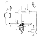
図1は、本発明が好適に適用されるハイブリッド車両用駆動装置10(以下、単に駆動装置10という)に係る駆動系統及び制御系統の構成を概念的に示す図である。図1に示すように、駆動装置10は、駆動源として機能するエンジン12及び電動機MGを備えており、それらエンジン12及び電動機MGにより発生させられた駆動力は、トルクコンバータ16、自動変速機(変速機)18、差動歯車装置20、及び左右1対の車軸22をそれぞれ介して左右1対の駆動輪24へ伝達されるように構成されている。電動機MG、トルクコンバータ16、及び自動変速機18は、何れもトランスミッションケース36(以下、ケース36という)内に収容されている。
FIG. 1 is a diagram conceptually showing the configuration of a drive system and a control system according to a hybrid vehicle drive device 10 (hereinafter simply referred to as drive device 10) to which the present invention is preferably applied. As shown in FIG. 1, the
エンジン12は、例えば、燃料が燃焼室内に直接噴射される筒内噴射型のガソリンエンジン等の内燃機関である。エンジン12の駆動(出力トルク)を制御するために、電子スロットル弁26を開閉制御するスロットルアクチュエータ28(図2参照)、燃料噴射制御を行う燃料噴射装置30(図2参照)、及び点火時期制御を行う点火装置32(図2参照)等を備えた出力制御装置14が設けられている。この出力制御装置14は、後述する電子制御装置(制御装置)60から供給される指令に従ってスロットル制御のためにスロットルアクチュエータ28により電子スロットル弁26を開閉制御する他、燃料噴射制御のために燃料噴射装置30による燃料噴射を制御し、点火時期制御のために点火装置32による点火時期を制御する等してエンジン12の出力制御を実行する。
The
トルクコンバータ16のポンプ翼車16pとタービン翼車16tとの間には、それらポンプ翼車16p及びタービン翼車16tが一体的に回転させられるように直結するロックアップクラッチLUが設けられている。このロックアップクラッチLUは、油圧制御回路34から供給される油圧に応じてその係合状態が係合(完全係合)、スリップ係合、乃至解放(完全解放)の間で制御されるようになっている。
Between the
電動機MGと駆動輪24との間の動力伝達経路に設けられた自動変速機18は、複数の油圧式摩擦係合装置を備え、それら係合装置の係合乃至解放の組み合わせに応じて予め定められた複数の変速段(例えば6速変速段等)を選択的に成立させる遊星歯車式の変速機構である。
The
電動機MGは、ケース36により軸心まわりの回転可能に支持されたロータ38と、そのロータ38の外周側においてケース36に一体的に固定されたステータ40とを備えており、駆動力を発生させるモータ(発動機)及び反力を発生させるジェネレータ(発電機)としての機能を有するモータジェネレータである。この電動機MGは、インバータ42を介してバッテリやコンデンサ等の蓄電装置44に接続されており、後述する電子制御装置60によりそのインバータ42を介してコイルに供給される駆動電流が調節されることにより、電動機MGの駆動が制御されるようになっている。換言すれば、インバータ42を介しての制御により電動機MGの出力トルクが増減させられるようになっている。
The electric motor MG includes a
エンジン12と電動機MGとの間の動力伝達経路には、係合状態に応じてその動力伝達経路における動力伝達を制御するクラッチK0が設けられている。すなわち、エンジン12の出力部材であるクランク軸48は、斯かるクラッチK0を介して電動機MGのロータ38に選択的に連結されるようになっている。このクラッチK0は、例えば、油圧アクチュエータによって係合制御される多板式の油圧式摩擦係合装置であり、油圧制御回路34から供給される油圧に応じてその係合状態が係合(完全係合)、スリップ係合、乃至解放(完全解放)の間で制御されるようになっている。
The power transmission path between the
図2に示すように、エンジン12は、シリンダヘッドとピストン50との間に設けられた燃焼室52と、その燃焼室52の吸気ポートに接続された吸気管54と、燃焼室52の排気ポートに接続された排気管56とを備えている。エンジン12では、吸気管54から燃焼室52に吸入される吸入空気に燃料噴射装置30から燃料が直射供給されて混合気が形成され、燃焼室52内でその混合気が点火装置32により点火されて燃焼する。これにより、エンジン12は駆動され、燃焼後の上記混合気は排気として排気管56内へと送り出される。
As shown in FIG. 2, the
また、図2に示すように、エンジン12の排気系、具体的にはそのエンジン12の排気管56内に、エンジン12の排気を浄化する触媒装置58が設けられている。上記触媒装置58は、例えばよく知られた三元触媒等から構成された触媒コンバータであり、エンジン12の排気に含まれる一酸化炭素(CO)、炭化水素(HC)、窒素酸化物(NOx)などの有害物質をその排気から除去又は削除して浄化する。また、触媒装置58は、その特性から定まる所定温度例えば400℃等より高いことによって、良好な排気浄化機能を発揮するものである。このため、前記所定温度以下の触媒温度である触媒装置58は、燃焼後の排気が高温であるので、エンジン12が駆動されその排気が通過させられることにより暖機され、上記良好な排気浄化性能を発揮する温度にまで高められる。
Further, as shown in FIG. 2, a
駆動装置10は、図1に例示するような制御系統を備えている。この図1に示す電子制御装置60は、CPU、RAM、ROM、及び入出力インターフェース等を備えた所謂マイクロコンピュータを含んで構成されており、CPUがRAMの一時記憶機能を利用しつつROMに予め記憶されたプログラムに従って信号処理を行うことにより、エンジン12の駆動制御、電動機MGの駆動制御、自動変速機18の変速制御、クラッチK0の係合力制御、及びロックアップクラッチLUの係合制御等の各種制御を実行する。本実施例においては、電子制御装置60がハイブリッド車両(駆動装置10)の制御装置に相当する。
The
図1に示すように、電子制御装置60には、駆動装置10に設けられた各センサにより検出される各種入力信号が供給されるようになっている。例えば、アクセルペダル62(図2参照)の踏込量に対応してアクセル開度センサ64により検出されるアクセル開度Acc(%)を表す信号、エンジン回転速度センサ66により検出されるエンジン12の回転速度NE(rpm)を表す信号、タービン回転速度センサ68により検出されるトルクコンバータ16のタービン翼車16tの回転速度NT(rpm)を表す信号、電動機回転速度センサ70により検出される電動機MGの回転速度NMG(rpm)を表す信号、車速センサ72により検出される車速V(km/h)を表す信号、触媒装置58の所定位置(例えば、略中央部など)の温度を検出できるように設けられた触媒温度センサ74により検出される触媒装置58の触媒温度TCATを示す信号、SOCセンサ76により検出される蓄電装置44の蓄電量(残容量、充電量)SOC(%)を表す信号等が電子制御装置60に入力される。
As shown in FIG. 1, the
また、電子制御装置60から、駆動装置10に設けられた各装置に各種出力信号が供給されるようになっている。例えば、エンジン12の駆動制御のためにそのエンジン12の出力制御装置14に供給される信号、電動機MGの駆動制御のためにインバータ42に供給される信号、自動変速機18の変速制御のために油圧制御回路34における複数の電磁制御弁に供給される信号、クラッチK0の係合制御のために油圧制御回路34におけるリニアソレノイド弁に供給される信号、ロックアップクラッチLUの係合制御のために油圧制御回路34におけるリニアソレノイド弁に供給される信号、及びライン圧制御のために油圧制御回路34におけるリニアソレノイド弁に供給される信号等が、電子制御装置60から各部へ供給される。
Various output signals are supplied from the
図3は、電子制御装置60に備えられた制御機能の要部を説明する機能ブロック線図である。この図3に示す触媒暖機制御部78は、触媒装置58の全体が活性化したと判断する予め定められた触媒温度TCAT以下の場合に、触媒暖機に専念させるために運転者の要求する要求駆動力の変化に対してエンジン12の出力を応答させず、エンジン12の回転変動、負荷変動が起こらないようにエンジントルクおよびエンジン回転数を略一定に保ち触媒装置58を暖機する触媒暖機制御を実施する。
FIG. 3 is a functional block diagram for explaining the main part of the control function provided in the
触媒温度判定部80は、触媒温度センサ74からの信号により触媒温度TCATを逐次検出しており、その検出された触媒温度TCATが予め定められた所定温度範囲内であるか否か、例えば200(℃)<TCATであるか否か、400(℃)<TCATであるか否かを判定する。なお、上記200(℃)は、予め実験等により定められた触媒装置58の上流側の端部の浄化能力が立ち上がる時の触媒装置58の中央部の触媒温度TCATであり、上記400(℃)は、予め実験等により定められた触媒装置58の全体の浄化能力が立ち上がる時の触媒装置58の中央部の触媒温度TCATである。
The catalyst
触媒暖機制御実施条件判定部82は、予め設定された触媒暖機制御実施条件が成立したか否かを判定する。上記触媒暖機制御実施条件とは、触媒暖機制御部78で前記触媒暖機制御を実施するか否かを判定するための条件であり、例えば、運転者が車両を走行可能な状態にするために操作するイグニッションスイッチがオンであり、且つ、蓄電装置44の充電残量SOC(%)が所定の暖機時充電残量判定値A1以上であり、且つ、触媒温度TCAT(℃)が所定の触媒温度判定値(例えば400℃)以下である場合に成立する。
The catalyst warm-up control execution
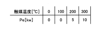
触媒暖機制御部78は、触媒暖機制御実施条件判定部82で前記触媒暖機制御実施条件が成立したと判定されると、予め定められた例えば図4に示すマップ等の関係から触媒温度センサ74によって検出される触媒温度TCATに基づいてエンジン出力Pe(kw)が設定され、その設定されたエンジン出力Pe(kw)となり且つエンジン12の回転数が予め定められたエンジン回転数(例えば1300rpm)となるようなエンジン動作点でエンジン12が運転するように出力制御装置14を制御する。なお、図4のマップに示す各触媒温度(℃)に対応するエンジン出力Pe(kw)は、触媒装置58の排気浄化能力を超えないように各触媒温度TCAT(℃)でエンジン12からの排気を浄化できるガス量に応じて予め実験等により設定されたものである。また、触媒暖機制御部78では、図4のマップに示すように、触媒温度センサ74により検出される触媒温度TCATがTCAT≦200(℃)の範囲内である場合にはエンジン出力Peは0(kw)に設定されている。また、触媒暖機制御部78では、上記触媒温度TCATがたとえば200(℃)<TCAT≦300(℃)の範囲内である場合にはエンジン出力Peは5(kw)に設定され、上記触媒温度TCATがたとえば300(℃)<TCAT≦400(℃)の範囲内である場合にはエンジン出力Peは10(kw)に設定されており、触媒温度TCATが上がることによって触媒装置58の排気浄化能力を超えないように段階的にエンジン出力Peが増加させられている。
When the catalyst warm-up control execution
また、触媒暖機制御部78は、前記触媒暖機制御中において、例えば触媒温度判定部80で触媒温度TCATが400(℃)<TCATであると判定されると、すなわち触媒装置58の全体の浄化能力が立ち上がったと判定されると、それまで継続していた上記触媒暖機制御を終了する。なお、触媒暖機制御部78では、例えば、車両状態が下記の状態の時でも上記触媒暖機制御を終了(解除)させる。すなわち、蓄電装置44の蓄電量SOC(%)が放電を許容できる下限値A1より小さい場合(SOC<A1)や、充電を許容できる上限値A2(例えば、75%)より大きい場合(SOC>A2)や、車速Vがエンジン12の回転数を引き上げないと車軸回転数が上がらなくなる上限車速B1(例えば、60km/h、6ATシステムでギアが6段目でエンジン回転数が1300rpmの時の車速)より速い場合(車速V>B1)や、運転者の要求出力がバッテリ出力だけでは応答できないバッテリの出力上限値C(例えば、35kw)より大きい場合(運転者の要求出力>C)や、運転者のトルク要求が電動機MGのトルクだけでは応答できないMGトルク上限値(例えば、250Nm)より大きい場合(運転者のトルク要求>D)等である。
Further, during the catalyst warm-up control, for example, when the catalyst
要求駆動力制御部84は、基本的には、運転者が要求する要求駆動力の変化を満たす走行となるように、例えばアクセル開度センサ64により検出されるアクセル開度Accおよび車速センサ72により検出される車速V等に基づいて、エンジン12の出力、電動機MGの出力、自動変速機18の変速を制御する。また、要求駆動力制御部84では、触媒暖機制御部78で前記触媒暖機制御が実施され終了するまでの間において、運転者の要求する要求駆動力の変化に対してエンジン12の回転変動、負荷変動が起こらないようにエンジントルクおよびエンジン回転数を略一定に保つと共に、その要求駆動力の変化を満たす走行となるように電動機MGの出力および自動変速機18の変速段が設定される。そして、上記設定された電動機MGの出力が得られるように電動機MGの出力を制御し、上記設定された変速段が成立させられるように油圧制御回路34を介して自動変速機18における複数の油圧式摩擦係合装置の係合乃至解放を制御する。また、要求駆動力制御部84では、上記触媒暖機制御中において、例えばクラッチK0の後段の回転数すなわち電動機MGの回転数がエンジン12の回転数に対して変化する場合には、エンジン12の回転数が変化しないように、自動変速機18による変速を行い且つクラッチK0をスリップさせることによりエンジン12の回転数を略一定にする。
The required driving
車両停車判定部86は、例えば車速センサ72により検出される車速Vによって車両が停車しているか否かを判定する。
The vehicle stop determination unit 86 determines whether or not the vehicle is stopped based on the vehicle speed V detected by the
触媒暖機制御部78は、車両停車判定部86で車両が停車していると判定され、且つ、触媒暖機制御実施条件判定部82で前記触媒暖機制御実施条件が成立したと判定されると、油圧制御回路34を介してロックアップクラッチLUを完全解放して、前記触媒暖機制御を実施する。
The catalyst warm-up
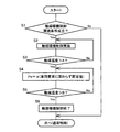
図5は、電子制御装置60において、車両走行中或いは車両停車中における前記触媒暖機制御の実行開始から終了までの制御作動の一例を説明するフローチャートである。
FIG. 5 is a flowchart for explaining an example of the control operation from the start to the end of the catalyst warm-up control while the vehicle is running or the vehicle is stopped in the
先ず、触媒暖機制御実施条件判定部82に対応するステップ(以下、ステップを省略する)S1において、前記触媒暖機制御を実施する触媒暖機制御実施条件が成立したか否かが判定される。このS1の判定が否定される場合には本ルーチンが終了させられるが肯定される場合には、触媒暖機制御部78に対応するS2が実行される。上記S2では、前記触媒暖機制御が実行される。つまり、図4に示すマップ等の関係から例えば触媒温度TCATがたとえばTCAT≦200(℃)である場合にはエンジン出力Peが0(kw)設定されて、エンジン12はそのエンジン出力Peが0(kw)となり且つそのエンジン12の回転数が例えば1300rpmとなるように運転させられる。
First, in step (hereinafter, step is omitted) S1 corresponding to the catalyst warm-up control execution
次に、触媒温度判定部80に対応するS3において、触媒温度TCATが200℃(A)<TCATであるか否かが判定される。このS3の判定が否定される場合には、継続してS2が実行される。すなわち、触媒温度TCATがTCAT≦200℃の時には、エンジン出力Peが0(kw)で略一定に且つエンジン12の回転数が1300rpmで略一定にエンジン12が運転させられる。
Next, in S3 corresponding to the catalyst
また、上記S3の判定が肯定される場合には、触媒暖機制御部78に対応するS4において、図4に示すマップ等の関係から触媒温度TCATによって決まるエンジン出力Pe(kw)が設定され、エンジン12はそのエンジン出力Peが設定されたエンジン出力となり且つエンジン12の回転数が1300rpmとなるように運転させられる。
Further, when the determination in S3 is affirmed, in S4 that corresponds to the catalyst warm-up
次に、触媒温度判定部80に対応するS5において、触媒温度TCATがたとえば400℃(B)<TCATであるか否かが判定される。このS5の判定が否定される場合には、継続してS4が実行される。すなわち、触媒温度TCATがたとえば200(℃)<TCAT≦300(℃)の時には、エンジン出力Peが5(kw)で略一定に且つエンジン回転数が1300rpmで略一定に運転させられる。また、触媒温度TCATがたとえば300(℃)<TCAT≦400(℃)の時には、エンジン出力Peが10(kw)で略一定に且つエンジン回転数が1300rpmで略一定に運転させられる。つまり、上記S4では、触媒装置58の排気浄化能力を超えないようにエンジン出力Peが上記S2に比較して増加させられ触媒装置58が暖機される。
Next, in S5 corresponding to the catalyst
上記S5の判定が肯定される場合には、触媒暖機制御部78に対応するS6において、前記S2で実行開始された前記触媒暖機制御が終了させられる。
If the determination in S5 is affirmative, in S6 corresponding to the catalyst warm-up
また、図5に示すフローチャートで前記触媒暖機制御が実施されている間において、運転者の要求駆動力の変化に対しては、要求駆動力制御部84において、その要求駆動力の変化に対してエンジン12の回転変動、負荷変動が起こらないようにエンジントルクおよびエンジン回転数を略一定に保つと共に、その要求駆動力の変化を満たす走行となるように電動機MGの出力および自動変速機18の変速にて応答させる。また、例えば車速Vによって電動機MGの回転数がエンジン12の回転数に対して変化する場合には、要求駆動力制御部84において、自動変速機18の変速およびクラッチK0をスリップさせることによって、エンジン12の回転数が変化しないようにエンジン12の回転数を略一定にさせる。
In addition, while the catalyst warm-up control is being performed in the flowchart shown in FIG. 5, the required driving
また、車両停車判定部86において、車両が停車していると判定され、且つ、前記S1で触媒暖機制御実施条件が成立すると、ロックアップクラッチLUが解放されて前記S2で前記触媒暖機制御が実施される。 When the vehicle stop determination unit 86 determines that the vehicle is stopped and the catalyst warm-up control execution condition is satisfied in S1, the lockup clutch LU is released, and the catalyst warm-up control is performed in S2. Is implemented.
上述のように、本実施例の駆動装置10の電子制御装置60によれば、前記触媒暖機制御中には、要求駆動力制御部84において、運転者の要求駆動力の変化を満たす走行となるように、電動機MGの出力を変化させ且つ自動変速機18の変速を行うので、走行中にエンジン12のトルクを略一定に保ったまま前記触媒暖機制御を適切に行うことができる。また、前記触媒暖機制御中には、触媒装置58の排気浄化能力を超えないようにエンジン出力Peを増加させてその触媒装置58を暖機させるので、エンジン12の熱効率がエンジン出力Peが低いものに比べて高くなる。これによって、駆動装置10において、触媒暖機時のエンジン12の熱効率を高くして燃費を向上させられる。
As described above, according to the
また、本実施例の駆動装置10の電子制御装置60によれば、前記触媒暖機制御中において、要求駆動力制御部84において、クラッチK0の後段の回転数すなわち電動機MGの回転数がエンジン12の回転数に対して変化する場合には、そのエンジン12の回転数が変化しないように、クラッチK0をスリップさせ且つ自動変速機18の変速を行う制御を行う。このため、走行中にエンジン12のトルクおよびエンジン12の回転数を維持したまま前記触媒暖機制御を適切に行うことができる。
Further, according to the
また、本実施例の駆動装置10の電子制御装置60によれば、ロックアップクラッチLU付きのトルクコンバータ16を備え、触媒暖機制御部78において、車両停止中に前記触媒暖機制御を行う場合、ロックアップクラッチLUを解放する。このため、車両停止中には、ロックアップクラッチLUが解放されることによりエンジン12と駆動輪24の車軸22との間の動力伝達が略遮断されるので、車両停車時に前記触媒暖機制御を適切に行うことができる。
Further, according to the
以上、本発明の実施例を図面に基づいて詳細に説明したが、その他の態様においても適用される。 As mentioned above, although the Example of this invention was described in detail based on drawing, it is applied also in another aspect.
例えば、前述の実施例の要求駆動力制御部84において、前記触媒暖機制御中の要求駆動力の変化は、電動機MGの出力の変化および自動変速機18の変速によって応答させていたが、例えば電動機MGの出力の変化だけで応答させたり、自動変速機18の変速だけで応答させても良い。すなわち、要求駆動力制御部84は、少なくとも電動機MGの出力を変化させるか自動変速機18の変速を行うかのいずれか一方を行うことによって要求駆動力の変化に応答させても良い。
For example, in the required driving
また、例えば、前述の実施例の要求駆動力制御部84において、クラッチK0の後段の回転数すなわち電動機MGの回転数がエンジン12の回転数に対して変化する場合には、クラッチK0をスリップさせ且つ自動変速機18の変速によって、エンジン12の回転数を略一定にさせていたが、例えばクラッチK0をスリップさせるだけでエンジン回転数を略一定にさせたり、自動変速機18の変速だけでエンジン回転数を略一定にさせても良い。すなわち、要求駆動力制御部84は、少なくともクラッチK0をスリップさせるか自動変速機18の変速を行うかのいずれか一方の制御を行うことによって、エンジン12の回転数を略一定にさせても良い。
Further, for example, in the required driving
また、例えば、前述の実施例において、自動変速機18は、遊星歯車式の変速機であったが、これ以外の変速機例えば平行軸式の変速機、CVT等を適用させても良い。
Further, for example, in the above-described embodiment, the
また、前述の実施例では、前記触媒暖機制御実施条件において蓄電装置44の充電残量SOC(%)が所定の暖機時充電残量判定値A1以上と示され、前記触媒暖機制御の終了(解除)条件において蓄電装置44の蓄電量SOC(%)が放電を許容できる下限値A1より小さい場合(SOC<A1)と示されており、上記所定の暖機時充電残量判定値A1と上記下限値A1とは同じ値に設定されていたが、例えばそれらの値A1が異なる値に設定されていても良い。 In the above-described embodiment, the remaining charge SOC (%) of the power storage device 44 in the catalyst warm-up control execution condition is indicated as a predetermined warm-up remaining charge determination value A1, and the catalyst warm-up control is performed. In the end (release) condition, it is indicated that the charged amount SOC (%) of the power storage device 44 is smaller than the lower limit value A1 at which discharge is permissible (SOC <A1), and the predetermined warm-up charge remaining amount determination value A1 is shown. Although the lower limit value A1 is set to the same value, for example, the value A1 may be set to a different value.
尚、上述したのはあくまでも一実施形態であり、本発明は当業者の知識に基づいて種々の変更、改良を加えた態様で実施することができる。 The above description is only an embodiment, and the present invention can be implemented in variously modified and improved forms based on the knowledge of those skilled in the art.
10:駆動装置(ハイブリッド車両用駆動装置)
12:エンジン
16:トルクコンバータ
18:自動変速機(変速機)
24:駆動輪
58:触媒装置
60:電子制御装置(制御装置)
78:触媒暖機制御部
84:要求駆動力制御部
86:車両停車判定部
K0:クラッチ
LU:ロックアップクラッチ
MG:電動機
TCAT:触媒温度
10: Drive device (drive device for hybrid vehicle)
12: Engine 16: Torque converter 18: Automatic transmission (transmission)
24: Drive wheel 58: Catalyst device 60: Electronic control device (control device)
78: Catalyst warm-up control unit 84: Required driving force control unit 86: Vehicle stoppage determination unit K0: Clutch LU: Lock-up clutch MG: Electric motor TCAT : Catalyst temperature
Claims (3)
前記触媒暖機制御中には、要求駆動力の変化を満たす走行となるように、少なくとも前記電動機の出力を変化させるか前記変速機の変速を行うかのいずれか一方を行うものであることを特徴とするハイブリッド車両の制御装置。 Provided in an engine provided with a catalyst device for purifying exhaust, an electric motor, a clutch provided in a power transmission path between the engine and the electric motor, and a power transmission path between the electric motor and drive wheels When the temperature of the catalyst device is equal to or lower than a predetermined catalyst temperature, the engine output is increased so as not to exceed the exhaust gas purification capacity of the catalyst device to warm the catalyst device. A control device for a hybrid vehicle that performs catalyst warm-up control.
During the catalyst warm-up control, at least one of changing the output of the electric motor or shifting the transmission so as to satisfy the change in the required driving force is performed. A hybrid vehicle control device.
車両停止中に前記触媒暖機制御を行う場合、前記ロックアップクラッチを解放する請求項1または2のハイブリッド車両の制御装置。 It has a torque converter with a lock-up clutch,
The control apparatus for a hybrid vehicle according to claim 1 or 2, wherein when the catalyst warm-up control is performed while the vehicle is stopped, the lock-up clutch is released.
Priority Applications (1)
| Application Number | Priority Date | Filing Date | Title |
|---|---|---|---|
| JP2013031520A JP2014159255A (en) | 2013-02-20 | 2013-02-20 | Control device for hybrid vehicle |
Applications Claiming Priority (1)
| Application Number | Priority Date | Filing Date | Title |
|---|---|---|---|
| JP2013031520A JP2014159255A (en) | 2013-02-20 | 2013-02-20 | Control device for hybrid vehicle |
Publications (1)
| Publication Number | Publication Date |
|---|---|
| JP2014159255A true JP2014159255A (en) | 2014-09-04 |
Family
ID=51611333
Family Applications (1)
| Application Number | Title | Priority Date | Filing Date |
|---|---|---|---|
| JP2013031520A Pending JP2014159255A (en) | 2013-02-20 | 2013-02-20 | Control device for hybrid vehicle |
Country Status (1)
| Country | Link |
|---|---|
| JP (1) | JP2014159255A (en) |
Cited By (12)
| Publication number | Priority date | Publication date | Assignee | Title |
|---|---|---|---|---|
| JP2016037252A (en) * | 2014-08-08 | 2016-03-22 | 日産自動車株式会社 | Control system of hybrid vehicle |
| JP2016037251A (en) * | 2014-08-08 | 2016-03-22 | 日産自動車株式会社 | Control system of hybrid vehicle |
| JP2019167846A (en) * | 2018-03-22 | 2019-10-03 | トヨタ自動車株式会社 | Vehicle control system |
| US11427344B2 (en) | 2019-03-01 | 2022-08-30 | Pratt & Whitney Canada Corp. | Cooling system configurations for an aircraft having hybrid-electric propulsion system |
| US11486472B2 (en) | 2020-04-16 | 2022-11-01 | United Technologies Advanced Projects Inc. | Gear sytems with variable speed drive |
| US11535392B2 (en) | 2019-03-18 | 2022-12-27 | Pratt & Whitney Canada Corp. | Architectures for hybrid-electric propulsion |
| US11574548B2 (en) | 2019-04-25 | 2023-02-07 | Pratt & Whitney Canada Corp. | Aircraft degraded operation ceiling increase using electric power boost |
| US11628942B2 (en) | 2019-03-01 | 2023-04-18 | Pratt & Whitney Canada Corp. | Torque ripple control for an aircraft power train |
| US11667391B2 (en) | 2019-08-26 | 2023-06-06 | Pratt & Whitney Canada Corp. | Dual engine hybrid-electric aircraft |
| US11697505B2 (en) | 2019-03-01 | 2023-07-11 | Pratt & Whitney Canada Corp. | Distributed propulsion configurations for aircraft having mixed drive systems |
| US11732639B2 (en) | 2019-03-01 | 2023-08-22 | Pratt & Whitney Canada Corp. | Mechanical disconnects for parallel power lanes in hybrid electric propulsion systems |
| US11738881B2 (en) | 2019-10-21 | 2023-08-29 | Hamilton Sundstrand Corporation | Auxiliary power unit systems |
Citations (5)
| Publication number | Priority date | Publication date | Assignee | Title |
|---|---|---|---|---|
| JPH09224303A (en) * | 1996-02-16 | 1997-08-26 | Nippon Soken Inc | Vehicle controller of hybrid car |
| JP2000320439A (en) * | 1999-05-10 | 2000-11-21 | Toyota Motor Corp | Vehicular drive control device |
| JP2003165359A (en) * | 2001-11-30 | 2003-06-10 | Aisin Aw Co Ltd | Automatic transmission control device, automatic transmission control method and its program |
| JP2005162081A (en) * | 2003-12-04 | 2005-06-23 | Nissan Motor Co Ltd | Method of starting engine of vehicle mounted with hybrid transmission when quickly increasing driving force |
| JP2012040915A (en) * | 2010-08-17 | 2012-03-01 | Toyota Motor Corp | Hybrid vehicle |
-
2013
- 2013-02-20 JP JP2013031520A patent/JP2014159255A/en active Pending
Patent Citations (5)
| Publication number | Priority date | Publication date | Assignee | Title |
|---|---|---|---|---|
| JPH09224303A (en) * | 1996-02-16 | 1997-08-26 | Nippon Soken Inc | Vehicle controller of hybrid car |
| JP2000320439A (en) * | 1999-05-10 | 2000-11-21 | Toyota Motor Corp | Vehicular drive control device |
| JP2003165359A (en) * | 2001-11-30 | 2003-06-10 | Aisin Aw Co Ltd | Automatic transmission control device, automatic transmission control method and its program |
| JP2005162081A (en) * | 2003-12-04 | 2005-06-23 | Nissan Motor Co Ltd | Method of starting engine of vehicle mounted with hybrid transmission when quickly increasing driving force |
| JP2012040915A (en) * | 2010-08-17 | 2012-03-01 | Toyota Motor Corp | Hybrid vehicle |
Cited By (13)
| Publication number | Priority date | Publication date | Assignee | Title |
|---|---|---|---|---|
| JP2016037251A (en) * | 2014-08-08 | 2016-03-22 | 日産自動車株式会社 | Control system of hybrid vehicle |
| JP2016037252A (en) * | 2014-08-08 | 2016-03-22 | 日産自動車株式会社 | Control system of hybrid vehicle |
| JP2019167846A (en) * | 2018-03-22 | 2019-10-03 | トヨタ自動車株式会社 | Vehicle control system |
| US11697505B2 (en) | 2019-03-01 | 2023-07-11 | Pratt & Whitney Canada Corp. | Distributed propulsion configurations for aircraft having mixed drive systems |
| US11427344B2 (en) | 2019-03-01 | 2022-08-30 | Pratt & Whitney Canada Corp. | Cooling system configurations for an aircraft having hybrid-electric propulsion system |
| US11732639B2 (en) | 2019-03-01 | 2023-08-22 | Pratt & Whitney Canada Corp. | Mechanical disconnects for parallel power lanes in hybrid electric propulsion systems |
| US11628942B2 (en) | 2019-03-01 | 2023-04-18 | Pratt & Whitney Canada Corp. | Torque ripple control for an aircraft power train |
| US11639228B2 (en) | 2019-03-01 | 2023-05-02 | Pratt & Whitney Canada Corp. | Engine layouts and associated compartmentalization for aircraft having hybrid-electric propulsion system |
| US11535392B2 (en) | 2019-03-18 | 2022-12-27 | Pratt & Whitney Canada Corp. | Architectures for hybrid-electric propulsion |
| US11574548B2 (en) | 2019-04-25 | 2023-02-07 | Pratt & Whitney Canada Corp. | Aircraft degraded operation ceiling increase using electric power boost |
| US11667391B2 (en) | 2019-08-26 | 2023-06-06 | Pratt & Whitney Canada Corp. | Dual engine hybrid-electric aircraft |
| US11738881B2 (en) | 2019-10-21 | 2023-08-29 | Hamilton Sundstrand Corporation | Auxiliary power unit systems |
| US11486472B2 (en) | 2020-04-16 | 2022-11-01 | United Technologies Advanced Projects Inc. | Gear sytems with variable speed drive |
Similar Documents
| Publication | Publication Date | Title |
|---|---|---|
| JP2014159255A (en) | Control device for hybrid vehicle | |
| US8491441B2 (en) | Hybrid vehicle control device | |
| US9108635B2 (en) | Control device of hybrid vehicle | |
| US20070246272A1 (en) | Control device for a hybrid electric vehicle | |
| US10486687B2 (en) | Hybrid vehicle and emission reduction strategy | |
| JP7132839B2 (en) | power train controller | |
| JP2008106675A (en) | Hybrid vehicle and method for controlling same | |
| JP2015140150A (en) | hybrid vehicle | |
| WO2013021504A1 (en) | Hybrid vehicle control device | |
| JP7124650B2 (en) | Hybrid vehicle control device | |
| JP5621492B2 (en) | Control device for hybrid vehicle | |
| CN108725429B (en) | Hybrid vehicle | |
| JP2007246009A (en) | Controller for hybrid electric car | |
| JP2009269429A (en) | Hybrid vehicle control unit | |
| US11247661B2 (en) | Control device and control method for hybrid vehicle | |
| JP2004278317A (en) | Vehicular speed reduction control device | |
| JP7342768B2 (en) | Hybrid vehicle control device | |
| JP2019077224A (en) | Control device for vehicle | |
| JP2004270512A (en) | Hybrid vehicle controller | |
| JP5239809B2 (en) | Vehicle control apparatus and control method | |
| JP6881366B2 (en) | Vehicle control system | |
| JP2021133692A (en) | Vehicular rotation speed control apparatus | |
| JP2015155276A (en) | Vehicle control device | |
| JP6435804B2 (en) | Control device for hybrid vehicle | |
| JP3912314B2 (en) | Hybrid vehicle combustion control system |
Legal Events
| Date | Code | Title | Description |
|---|---|---|---|
| A621 | Written request for application examination |
Free format text: JAPANESE INTERMEDIATE CODE: A621 Effective date: 20150424 |
|
| A131 | Notification of reasons for refusal |
Free format text: JAPANESE INTERMEDIATE CODE: A131 Effective date: 20160315 |
|
| A02 | Decision of refusal |
Free format text: JAPANESE INTERMEDIATE CODE: A02 Effective date: 20161004 |