JP2014155694A - Ophthalmologic apparatus and ophthalmologic method - Google Patents
Ophthalmologic apparatus and ophthalmologic method Download PDFInfo
- Publication number
- JP2014155694A JP2014155694A JP2014001524A JP2014001524A JP2014155694A JP 2014155694 A JP2014155694 A JP 2014155694A JP 2014001524 A JP2014001524 A JP 2014001524A JP 2014001524 A JP2014001524 A JP 2014001524A JP 2014155694 A JP2014155694 A JP 2014155694A
- Authority
- JP
- Japan
- Prior art keywords
- image
- fundus
- images
- polarization
- tomographic
- Prior art date
- Legal status (The legal status is an assumption and is not a legal conclusion. Google has not performed a legal analysis and makes no representation as to the accuracy of the status listed.)
- Pending
Links
Images


Classifications
-
- A—HUMAN NECESSITIES
- A61—MEDICAL OR VETERINARY SCIENCE; HYGIENE
- A61B—DIAGNOSIS; SURGERY; IDENTIFICATION
- A61B3/00—Apparatus for testing the eyes; Instruments for examining the eyes
- A61B3/0016—Operational features thereof
- A61B3/0025—Operational features thereof characterised by electronic signal processing, e.g. eye models
-
- A—HUMAN NECESSITIES
- A61—MEDICAL OR VETERINARY SCIENCE; HYGIENE
- A61B—DIAGNOSIS; SURGERY; IDENTIFICATION
- A61B3/00—Apparatus for testing the eyes; Instruments for examining the eyes
- A61B3/0016—Operational features thereof
- A61B3/0041—Operational features thereof characterised by display arrangements
- A61B3/0058—Operational features thereof characterised by display arrangements for multiple images
-
- A—HUMAN NECESSITIES
- A61—MEDICAL OR VETERINARY SCIENCE; HYGIENE
- A61B—DIAGNOSIS; SURGERY; IDENTIFICATION
- A61B3/00—Apparatus for testing the eyes; Instruments for examining the eyes
- A61B3/10—Objective types, i.e. instruments for examining the eyes independent of the patients' perceptions or reactions
- A61B3/102—Objective types, i.e. instruments for examining the eyes independent of the patients' perceptions or reactions for optical coherence tomography [OCT]
-
- A—HUMAN NECESSITIES
- A61—MEDICAL OR VETERINARY SCIENCE; HYGIENE
- A61B—DIAGNOSIS; SURGERY; IDENTIFICATION
- A61B3/00—Apparatus for testing the eyes; Instruments for examining the eyes
- A61B3/10—Objective types, i.e. instruments for examining the eyes independent of the patients' perceptions or reactions
- A61B3/12—Objective types, i.e. instruments for examining the eyes independent of the patients' perceptions or reactions for looking at the eye fundus, e.g. ophthalmoscopes
- A61B3/1225—Objective types, i.e. instruments for examining the eyes independent of the patients' perceptions or reactions for looking at the eye fundus, e.g. ophthalmoscopes using coherent radiation
-
- A—HUMAN NECESSITIES
- A61—MEDICAL OR VETERINARY SCIENCE; HYGIENE
- A61B—DIAGNOSIS; SURGERY; IDENTIFICATION
- A61B5/00—Measuring for diagnostic purposes; Identification of persons
- A61B5/0059—Measuring for diagnostic purposes; Identification of persons using light, e.g. diagnosis by transillumination, diascopy, fluorescence
- A61B5/0062—Arrangements for scanning
- A61B5/0066—Optical coherence imaging
-
- G—PHYSICS
- G01—MEASURING; TESTING
- G01B—MEASURING LENGTH, THICKNESS OR SIMILAR LINEAR DIMENSIONS; MEASURING ANGLES; MEASURING AREAS; MEASURING IRREGULARITIES OF SURFACES OR CONTOURS
- G01B9/00—Measuring instruments characterised by the use of optical techniques
- G01B9/02—Interferometers
- G01B9/02015—Interferometers characterised by the beam path configuration
- G01B9/02027—Two or more interferometric channels or interferometers
-
- G—PHYSICS
- G01—MEASURING; TESTING
- G01B—MEASURING LENGTH, THICKNESS OR SIMILAR LINEAR DIMENSIONS; MEASURING ANGLES; MEASURING AREAS; MEASURING IRREGULARITIES OF SURFACES OR CONTOURS
- G01B9/00—Measuring instruments characterised by the use of optical techniques
- G01B9/02—Interferometers
- G01B9/02015—Interferometers characterised by the beam path configuration
- G01B9/02029—Combination with non-interferometric systems, i.e. for measuring the object
- G01B9/0203—With imaging systems
-
- G—PHYSICS
- G01—MEASURING; TESTING
- G01B—MEASURING LENGTH, THICKNESS OR SIMILAR LINEAR DIMENSIONS; MEASURING ANGLES; MEASURING AREAS; MEASURING IRREGULARITIES OF SURFACES OR CONTOURS
- G01B9/00—Measuring instruments characterised by the use of optical techniques
- G01B9/02—Interferometers
- G01B9/02041—Interferometers characterised by particular imaging or detection techniques
- G01B9/02044—Imaging in the frequency domain, e.g. by using a spectrometer
-
- G—PHYSICS
- G01—MEASURING; TESTING
- G01B—MEASURING LENGTH, THICKNESS OR SIMILAR LINEAR DIMENSIONS; MEASURING ANGLES; MEASURING AREAS; MEASURING IRREGULARITIES OF SURFACES OR CONTOURS
- G01B9/00—Measuring instruments characterised by the use of optical techniques
- G01B9/02—Interferometers
- G01B9/02055—Reduction or prevention of errors; Testing; Calibration
- G01B9/02075—Reduction or prevention of errors; Testing; Calibration of particular errors
- G01B9/02076—Caused by motion
-
- G—PHYSICS
- G01—MEASURING; TESTING
- G01B—MEASURING LENGTH, THICKNESS OR SIMILAR LINEAR DIMENSIONS; MEASURING ANGLES; MEASURING AREAS; MEASURING IRREGULARITIES OF SURFACES OR CONTOURS
- G01B9/00—Measuring instruments characterised by the use of optical techniques
- G01B9/02—Interferometers
- G01B9/0209—Low-coherence interferometers
- G01B9/02091—Tomographic interferometers, e.g. based on optical coherence
-
- G—PHYSICS
- G01—MEASURING; TESTING
- G01B—MEASURING LENGTH, THICKNESS OR SIMILAR LINEAR DIMENSIONS; MEASURING ANGLES; MEASURING AREAS; MEASURING IRREGULARITIES OF SURFACES OR CONTOURS
- G01B2290/00—Aspects of interferometers not specifically covered by any group under G01B9/02
- G01B2290/45—Multiple detectors for detecting interferometer signals
-
- G—PHYSICS
- G01—MEASURING; TESTING
- G01B—MEASURING LENGTH, THICKNESS OR SIMILAR LINEAR DIMENSIONS; MEASURING ANGLES; MEASURING AREAS; MEASURING IRREGULARITIES OF SURFACES OR CONTOURS
- G01B2290/00—Aspects of interferometers not specifically covered by any group under G01B9/02
- G01B2290/70—Using polarization in the interferometer
Abstract
Description
本発明は、被検眼の画像を取得する眼科装置及び眼科方法に関する。 The present invention relates to an ophthalmologic apparatus and an ophthalmologic method for acquiring an image of an eye to be examined.
Description of the Related Art Description of the Related Art
多波長光波干渉を利用した光コヒーレンストモグラフィ(Optical Coherence Tomography:以下、OCT)は、試料(特に眼底)の断層画像を高分解能に得ることができる。 Optical coherence tomography (hereinafter referred to as OCT) using multiwavelength lightwave interference can obtain a tomographic image of a sample (particularly the fundus) with high resolution.
近年、眼科用OCT装置において、眼底組織の形状をイメージングする通常のOCT画像に加えて、眼底組織の光学特性の一つである偏光パラメータ(リターデーションとオリエンテーション)を用いてイメージングする偏光OCT画像が取得されている。 In recent years, in an ophthalmic OCT apparatus, in addition to a normal OCT image for imaging the shape of the fundus tissue, a polarization OCT image for imaging using a polarization parameter (retardation and orientation), which is one of the optical characteristics of the fundus tissue, has been developed. Has been acquired.
偏光OCTは、偏光パラメータを利用して、偏光OCT画像を構成し、眼底組織の区別やセグメンテーションを行うことができる。偏光OCTは、試料を観察する測定光に円偏光に変調した光を用い、干渉光を2つの直交する直線偏光として分割して検出し、偏光OCT画像を生成する(特許文献1参照)。 Polarization OCT can make use of polarization parameters to construct a polarization OCT image to distinguish and segment the fundus tissue. Polarization OCT uses light modulated into circularly polarized light as measurement light for observing a sample, divides and detects interference light as two orthogonal linearly polarized lights, and generates a polarized OCT image (see Patent Document 1).
しかしながら、特許文献1には、偏光OCT画像の画質を向上する手法については何ら開示されていない。本発明の目的は、偏光OCT画像の画質を向上することである。 However, Patent Document 1 does not disclose any technique for improving the image quality of a polarized OCT image. An object of the present invention is to improve the image quality of polarized OCT images.
本発明に係る眼科装置は、
異なる時刻に被検眼の眼底を撮像して得た複数の眼底画像と、前記複数の眼底画像よりも少ない数であり且つ前記複数の眼底画像とは異なる時刻に前記被検眼の眼底を撮像して得た少なくとも1つの眼底画像とを取得する眼底画像取得手段と、
前記複数の眼底画像を平均化して新たな眼底画像を生成する手段と、
前記生成された新たな眼底画像から特徴領域を抽出する抽出手段と、
前記抽出された特徴領域と前記少なくとも1つの眼底画像とに基づいて、前記新たな眼底画像に対応する前記眼底の第1の偏光断層画像と前記少なくとも1つの眼底画像に対応する前記眼底の第2の偏光断層画像との位置が補正されるように、前記眼底を追尾する手段と、を有する。
また、本発明に係る眼科方法は、
異なる時刻に被検眼の眼底を撮像して得た複数の眼底画像と、前記複数の眼底画像よりも少ない数であり且つ前記複数の眼底画像とは異なる時刻に前記被検眼の眼底を撮像して得た少なくとも1つの眼底画像とを取得する工程と、
前記複数の眼底画像を平均化して新たな眼底画像を生成する工程と、
前記生成された新たな眼底画像から特徴領域を抽出する工程と、
前記抽出された特徴領域と前記少なくとも1つの眼底画像とに基づいて、前記新たな眼底画像に対応する前記眼底の第1の偏光断層画像と前記少なくとも1つの眼底画像に対応する前記眼底の第2の偏光断層画像との位置が補正されるように、前記眼底を追尾する工程と、を有する。
The ophthalmic apparatus according to the present invention is
A plurality of fundus images obtained by imaging the fundus of the eye to be examined at different times and a number smaller than the plurality of fundus images and the fundus of the eye to be examined at times different from the plurality of fundus images Fundus image acquisition means for acquiring the obtained at least one fundus image;
Means for averaging the plurality of fundus images to generate a new fundus image;
Extraction means for extracting a feature region from the generated new fundus image;
Based on the extracted feature region and the at least one fundus image, a first polarized tomographic image of the fundus corresponding to the new fundus image and a second of the fundus corresponding to the at least one fundus image. Means for tracking the fundus so that the position with respect to the polarization tomographic image is corrected.
In addition, the ophthalmic method according to the present invention includes:
A plurality of fundus images obtained by imaging the fundus of the eye to be examined at different times and a number smaller than the plurality of fundus images and the fundus of the eye to be examined at times different from the plurality of fundus images Obtaining at least one fundus image obtained;
Averaging the plurality of fundus images to generate a new fundus image;
Extracting a feature region from the generated new fundus image;
Based on the extracted feature region and the at least one fundus image, a first polarized tomographic image of the fundus corresponding to the new fundus image and a second of the fundus corresponding to the at least one fundus image. Tracking the fundus so that the position with respect to the polarization tomographic image is corrected.
本発明によれば、偏光OCT画像の画質を向上することができる。 According to the present invention, the image quality of a polarized OCT image can be improved.
本発明に係る撮影装置は、被検眼、皮膚、内臓等の被検体に適用することができる。また、本発明に係る撮影装置としては、例えば、眼科装置や内視鏡等である。以下、本発明の一例として、本実施形態に係る眼科装置について、図面を用いて詳細に説明する。 The imaging apparatus according to the present invention can be applied to a subject such as an eye to be examined, skin, or internal organs. In addition, examples of the photographing apparatus according to the present invention include an ophthalmologic apparatus and an endoscope. Hereinafter, as an example of the present invention, an ophthalmologic apparatus according to the present embodiment will be described in detail with reference to the drawings.
[装置の全体構成]
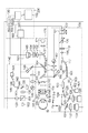
図1は、本実施形態における撮影装置の一例である「眼科装置」の全体構成の概略図である。なお、後述する信号処理部190の少なくとも一部を「画像処理装置」とみなすことができ、また、この場合、「眼科装置」全体を「眼科システム」、あるいは「撮影装置」全体を「撮影システム」とみなすこともできる。
[Overall configuration of the device]
FIG. 1 is a schematic diagram of the overall configuration of an “ophthalmologic apparatus” that is an example of an imaging apparatus according to the present embodiment. Note that at least a part of the
本装置は、偏光OCT(Polarization Sensitive OCT;以下、PS−OCT)100、偏光を利用した走査型検眼鏡(Polarization Sensitive Scanning Laser Ophothalmoscope:以下、PS−SLO)140、前眼部撮像部160、内部固視灯170、制御部200から構成される。
The apparatus includes a polarization OCT (Polarization Sensitive OCT; hereinafter referred to as PS-OCT) 100, a scanning optic ophthalmoscope (hereinafter referred to as PS-SLO) 140, an anterior
内部固視灯170を点灯して被検眼に注視させた状態で、前眼部観察部160により観察される被検体の前眼部の画像を用いて、装置のアライメントが行われる。アライメント完了後に、PS−OCT100とPS−SLO140による眼底の撮像が行われる。
The apparatus is aligned using an image of the anterior segment of the subject observed by the anterior
<PS−OCT100の構成>
PS−OCT100の構成について説明する。
<Configuration of PS-OCT100>
A configuration of the PS-OCT 100 will be described.
光源101は、低コヒーレント光源であるSLD光源(Super Luminescent Diode)であり、例えば、中心波長850nm、バンド幅50nmの光を出射する。光源101としてSLDを用いたが、ASE光源(Amplified Spontaneous Emission)等、低コヒーレント光が出射できる光源であれば何れでも良い。
The
光源101から出射された光は、PM(Polarization Maintaining)ファイバ102、偏光コントローラ103を介して、偏光保持機能を有したファイバカップラ104に導かれ、測定光(以下、「断層画像用の測定光」や「OCT測定光」ともいう)と、測定光に対応する参照光とに分割される。
Light emitted from the
偏光コントローラ103は、光源101から出射された光の偏光の状態を調整するものであり、直線偏光に調整される。ファイバカップラ104の分岐比は、90(参照光):10(測定光)である。
The
測定光は、PMファイバ105を介してコリメータ106から平行光として出射される。出射された測定光は、眼底Erにおいて測定光を水平方向にスキャンするガルバノミラーから構成されるXスキャナ107、レンズ108、109、眼底Erにおいて測定光を垂直方向にスキャンするガルバノミラーから構成されるYスキャナ110を介し、ダイクロイックミラー111に到達する。Xスキャナ107、Yスキャナ110は、駆動制御部180により制御され、眼底Erの所望の範囲で測定光を走査することができる。なお、測定光が走査される眼底上の範囲は、断層画像の取得範囲、断層画像の取得位置、測定光の照射位置としてみなすことができる。また、Xスキャナ107、Yスキャナ110は、PS−OCT用の走査手段の一例であり、共通のXYスキャナとして構成しても良い。ダイクロイックミラー111は、800nm〜900nmの光を反射し、それ以外の光を透過する特性を有する。
The measurement light is emitted as parallel light from the
ダイクロイックミラー111により反射された測定光は、レンズ112を介し、光軸を回転軸としてP偏光からS偏光に対して45°傾けて設置されたλ/4偏光板113を通過することにより、位相が90°ずれ、円偏光の光に偏光制御される。なお、λ/4偏光板113は、測定光の偏光状態を調整する測定光用の偏光調整部材の一例である。ここで、後述するPS−SLO光学系を適用する場合、λ/4偏光板113をPS−OCT光学系の一部とPS−SLO光学系の一部との共通光路に設けることができる。これにより、PS−SLO光学系で取得した画像と、PS−OCT光学系で取得した画像とに生じる偏光状態のばらつきを比較的に抑制することができる。このとき、PS−SLO用の走査手段と、PS−OCT用の走査手段とは、互いに共役な位置に設けられ、被検眼の瞳と共役な位置に設けることができる。なお、λ/4偏光板113の傾きは、λ/4偏光板113の状態の一例であり、例えば、偏光ビームスプリッタを内蔵したファイバカップラ123の偏光分割面の光軸を回転軸とした所定の位置からの角度である。
The measurement light reflected by the
また、λ/4偏光板113を光路に対して挿脱可能に構成することができる。例えば、光軸あるいは光軸に平行な軸を回転軸としてλ/4偏光板113を回転する機械的な構成が考えられる。これにより、SLO光学系とPS−SLO光学系とを簡単に切り換え可能な小型な装置を実現することができる。また、OCT光学系とPS−OCT光学系とを簡単に切り換え可能な小型な装置を実現することができる。 Further, the λ / 4 polarizing plate 113 can be configured to be detachable from the optical path. For example, a mechanical configuration in which the λ / 4 polarizing plate 113 is rotated about an optical axis or an axis parallel to the optical axis as a rotation axis is conceivable. Thereby, it is possible to realize a small apparatus capable of easily switching between the SLO optical system and the PS-SLO optical system. Further, it is possible to realize a small apparatus that can easily switch between the OCT optical system and the PS-OCT optical system.
ここで、被検眼に入射される光は、λ/4偏光板を45°傾けて設置することで円偏光の光に偏光制御されるが、被検眼の特性により眼底Erにおいて円偏光とならない場合がある。そのため、駆動制御部180の制御により、λ/4偏光板の傾きを微調整できるように構成されている。
Here, the light incident on the eye to be examined is controlled to be circularly polarized light by tilting the λ / 4 polarizing plate by 45 °, but is not circularly polarized on the fundus Er due to the characteristics of the eye to be examined There is. For this reason, the inclination of the λ / 4 polarizing plate can be finely adjusted under the control of the
円偏光に偏光制御された測定光は、ステージ116上に乗ったフォーカスレンズ114により、被検体である眼の前眼部Eaを介し、眼底Erの網膜層にフォーカスされる。眼底Erを照射した測定光は各網膜層で反射・散乱し、上述の光学経路をファイバカップラ104に戻る。
The measurement light whose polarization is controlled to be circularly polarized is focused on the retinal layer of the fundus Er by the
一方、ファイバカプラ104で分岐された参照光は、PMファイバ117を介してコリメータ118から平行光として出射される。出射された参照光は測定光と同様に、光軸を回転軸としてP偏光からS偏光に対して22.5°傾けて設置されたλ/4偏光板119で偏光制御される。なお、λ/4偏光板119は、参照光の偏光状態を調整する参照光用の偏光調整部材の一例である。参照光は分散補償ガラス120介し、コヒーレンスゲートステージ121上のミラー122で反射され、ファイバカップラ104に戻る。参照光は、λ/4偏光板119を二度通過する事で直線偏光の光がファイバカップラ104に戻ることになる。
On the other hand, the reference light branched by the
コヒーレンスゲートステージ121は、被検者の眼軸長の相違等に対応する為、駆動制御部180で制御される。なお、コヒーレンスゲートとは、測定光の光路における参照光の光路長に対応する位置のことである。本実施形態では、参照光の光路長を変更しているが、測定光の光路と参照光の光路との光路長差を変更できれば良い。
The
ファイバカップラ104に戻った戻り光と参照光とは合波されて干渉光(以下、「合波光」ともいう)となり、偏光ビームスプリッタを内蔵したファイバカップラ123に入射され、異なる偏光方向の光であるP偏光の光とS偏光の光とに分岐比50:50で分割される。
The return light that has returned to the
P偏光の光は、PMファイバ124、コリメータ130を介し、グレーティング131により分光されレンズ132、ラインカメラ133で受光される。同様に、S偏光の光は、PMファイバ125、コリメータ126を介し、グレーティング127により分光されレンズ128、ラインカメラ129で受光される。なお、グレーティング127、131、ラインカメラ129、133は、各偏光の方向に合わせて配置されている。
P-polarized light is split by the grating 131 through the
ラインカメラ129、133でそれぞれ受光した光は、光の強度に応じた電気信号として出力され、断層画像生成部の一例である信号処理部190で受ける。
The light received by the
λ/4偏光板113、119の傾きに関して、偏光ビームスプリッタの偏光分割面の傾きを基準に自動的に調整することができるが、眼底の視神経乳頭中心と黄斑中心を結んだ直線に対して自動的に調整しても良い。このとき、λ/4偏光板113、119の傾きを検知する傾き検知部(不図示)を有することが好ましい。この傾き検知部により、現在の傾きと所定の傾きになったことを検知することができる。もちろん、受光した光の強度に基づいて、λ/4偏光板113、119の傾き具合を検知し、所定の強度になるように傾きを調整しても良い。なお、後述するように、GUI上に傾きを示すオブジェクトを表示して、ユーザがマウスを用いて調整しても良い。また、偏光基準として鉛直方向を基準にして偏光ビームスプリッタ、λ/4偏光板113、119を調整しても同様の効果が得られる。 The tilt of the λ / 4 polarizing plates 113 and 119 can be automatically adjusted based on the tilt of the polarization splitting surface of the polarizing beam splitter, but automatically with respect to the straight line connecting the center of the optic disc of the fundus and the center of the macula. May be adjusted. At this time, it is preferable to have an inclination detector (not shown) that detects the inclination of the λ / 4 polarizing plates 113 and 119. This inclination detection unit can detect that the current inclination and the predetermined inclination have been reached. Of course, the inclination of the λ / 4 polarizing plates 113 and 119 may be detected based on the intensity of the received light, and the inclination may be adjusted so as to have a predetermined intensity. As will be described later, an object indicating inclination may be displayed on the GUI, and the user may adjust using a mouse. The same effect can be obtained by adjusting the polarization beam splitter and the λ / 4 polarizing plates 113 and 119 with respect to the vertical direction as the polarization reference.
<PS−SLO140の構成>
PS−SLO140の構成について説明する。
<Configuration of PS-
The configuration of the PS-
光源141は、半導体レーザであり、本実施例では、例えば、中心波長780nmの光を出射する。光源141から出射された測定光(以下、「眼底画像用の測定光」や「SLO測定光」ともいう)は、PMファイバ142を介し、偏光コントローラ145で直線偏光になるよう偏光制御され、コリメータ143から平行光として出射される。出射された測定光は穴あきミラー144の穴あき部を通過し、レンズ155を介し、眼底Erにおいて測定光を水平方向にスキャンするガルバノミラーから構成されるXスキャナ146、レンズ147、148、眼底Erにおいて測定光を垂直方向にスキャンするガルバノミラーから構成されるYスキャナ149を介し、ダイクロイックミラー154に到達する。Xスキャナ146、Yスキャナ149は駆動制御部180により制御され、眼底上で所望の範囲を測定光で走査できる。なお、Xスキャナ146、Yスキャナ149は、PS−SLO用の走査手段の一例であり、共通のXYスキャナとして構成しても良い。ダイクロイックミラー154は、760nm〜800nmを反射し、それ以外の光を透過する特性を有する。
The
ダイクロイックミラー154にて反射された直線偏光の測定光は、PS−OCT100と同様の光路を経由し、眼底Erに到達する。
The linearly polarized measurement light reflected by the
眼底Erを照射した測定光は、眼底Erで反射・散乱され、上述の光学経路をたどり穴あきミラー144に達する。穴あきミラー144で反射された光が、レンズ150を介し、偏光ビームスプリッタ151にて異なる偏光方向の光(本実施形態では、P偏光の光とS偏光の光)に分割され、アバランシェフォトダイオード(APD)152、153で受光され、電気信号に変換されて、眼底画像生成部の一例でもある信号処理部190で受ける。
The measurement light applied to the fundus Er is reflected and scattered by the fundus Er and reaches the
ここで、穴あきミラー144の位置は、被検眼の瞳孔位置と共役となっており、眼底Erに照射された測定光が反射・散乱された光のうち、瞳孔周辺部を通った光が、穴あきミラー144によって反射される。
Here, the position of the
本実施例では、PS−OCT、PS−SLOともにPMファイバを用いたが、シングルモードファイバー(SMF)でも偏光コントローラを用い偏光を制御する事で同様の構成と効果が得られる。 In this embodiment, the PM fiber is used for both PS-OCT and PS-SLO, but the same configuration and effect can be obtained by controlling the polarization using a polarization controller even with a single mode fiber (SMF).
<前眼部撮像部160>
前眼部撮像部160について説明する。
<Anterior
The anterior
前眼部撮像部160は、波長1000nmの照明光を発するLED115−a、115−bから成る照明光源115により前眼部Eaを照射する。前眼部Eaで反射され光は、レンズ114、偏光板113、レンズ112、ダイクロイックミラー111、154を介し、ダイクロイックミラー161に達する。ダイクロイックミラー161は、980nm〜1100nmの光を反射し、それ以外の光を透過する特性を有する。ダイクロイックミラー161で反射された光は、レンズ162、163、164を介し、前眼部カメラ165で受光される。前眼部カメラ165で受光された光は、電気信号に変換され、信号処理部190で受ける。
The anterior
<内部固視灯170>
内部固視灯170について説明する。
<
The
内部固視灯170は、内部固視灯用表示部171、レンズ172で構成される。内部固視灯用表示部171として複数の発光ダイオード(LD)がマトリックス状に配置されたものを用いる。発光ダイオードの点灯位置は、駆動制御部180の制御により撮像したい部位に合わせて変更される。内部固視灯用表示部171からの光は、レンズ172を介し、被検眼に導かれる。内部固視灯用表示部171から出射される光は520nmで、制御部180により所望のパターンが表示される。
The
<制御部200>
本装置全体を制御するための制御部200について説明する。
<
A
制御部200は、駆動制御部180、信号処理部190、表示制御部191、表示部192から構成される。
The
駆動制御部180は、上述の通り各部を制御する。
The
信号処理部190は、画像生成部193と画像解析部194と追尾制御部195から構成される。信号処理部190は、ラインカメラ129及び133、APD152及び153、前眼部カメラ165からそれぞれ出力される信号に基づき、画像の生成、生成された画像の解析、解析結果の可視化情報の生成、及び追尾制御を行う。なお、画像の生成、解析、追尾などの詳細については後述する。
The
表示制御部191は、眼底画像取得部(不図示)と断層画像取得部(不図示)により、断層画像生成部と眼底画像生成部とでそれぞれ生成された画像を取得した画像等を表示部192の表示画面に表示させる。ここで、表示部192は、例えば、液晶等のディスプレイである。なお、信号処理部190で生成された画像データは、表示制御部191に有線で送信されても良いし、無線で送信されても良い。この場合、表示制御部191を画像処理装置とみなすことができる。なお、撮影システムとして、眼底画像取得部がSLO光学系を含み、断層画像取得部がOCT光学系を含むように構成しても良い。なお、本明細書において、被検眼以外の被検体の場合、「眼底画像(眼底輝度画像)」を「平面画像(平面輝度画像)」と換言することができ、また、「眼底画像取得部」を「平面画像取得部」と換言することができる。
The
表示部192は、表示制御部191の制御の下、後述するように種々の情報を示す表示形態を表示する。なお、表示制御部191からの画像データは、表示部192に有線で送信されても良いし、無線で送信されても良い。また、表示部192等は、制御部200に含まれているが、本発明はこれに限らず、制御部200とは別に設けられても良い。また、表示制御部191と表示部192とを一体的に構成した、ユーザが持ち運び可能な装置の一例であるタブレットでも良い。この場合、表示部にタッチパネル機能を搭載させ、タッチパネル上で画像の表示位置の移動、拡大縮小、表示される画像の変更等の操作可能に構成することが好ましい。
The
[画像処理]
次に、信号処理部190を構成する画像生成部193における画像生成について説明する。
[Image processing]
Next, image generation in the
画像生成部193は、ラインカメラ129、133から出力されたそれぞれの干渉信号に対して、一般的なSD−OCT(Spectral Domain OCT)に用いられる再構成処理を行うことで、各偏光成分に基づいた2つの断層画像である第一の偏光に対応する断層画像と、第二の偏光に対応する断層画像とを生成する。
The
まず、画像生成部193は、干渉信号から固定パターンノイズ除去を行う。固定パターンノイズ除去は検出した複数のAスキャン信号を平均することで固定パターンノイズを抽出し、これを入力した干渉信号から減算することで行われる。
First, the
次に、画像生成部193は、干渉信号を波長から波数に変換し、フーリエ変換を行うことによって、偏光状態を示す断層信号を生成する。
Next, the
以上の処理を2つの偏光成分の干渉信号に対して行うことにより、2つの断層画像が生成される。 By performing the above processing on the interference signals of the two polarization components, two tomographic images are generated.
また、画像生成部193は、APD152、153から出力された信号を、Xスキャナ146、Yスキャナ149の駆動に同期して整列させることにより、各偏光成分に基づいた2つの眼底画像である第一の偏光に対応する眼底画像と、第二の偏光に対応する眼底画像とを生成する。
In addition, the
<断層輝度画像あるいは眼底輝度画像の生成>
画像生成部193は、前述した2つの断層信号から断層輝度画像を生成する。
断層輝度画像は、従来のOCTにおける断層画像と基本的に同じもので、その画素値rは各ラインセンサ129、133から得られた断層信号AHおよびAVから(式1)によって計算される。
<Generation of tomographic luminance image or fundus luminance image>
The
Tomographic luminance image is calculated prior basically the same as the tomographic image at OCT, the pixel value r from the fault signals A H and A V obtained from the

また、同様に、2つの眼底画像から眼底輝度画像を生成する。 Similarly, a fundus luminance image is generated from two fundus images.
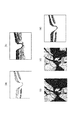
図2(a)に視神経乳頭部の輝度画像の例を示す。 FIG. 2A shows an example of a luminance image of the optic nerve head.
なお、表示制御部191は、λ/4偏光板113を光路から外している場合に、従来のOCTの手法により取得した断層輝度画像を表示部192に表示させても良いし、従来のSLOの手法により取得した眼底輝度画像を表示部192に表示させても良い。
When the λ / 4 polarizing plate 113 is removed from the optical path, the
<リターデーション画像の生成>
画像生成部193は、互いに直行する偏光成分の断層画像からリターデーション画像を生成する。
<Generation of retardation image>
The
リターデーション画像の各画素の値δは、断層画像を構成する各画素の位置において、垂直偏光成分と水平偏光成分とが被検眼で受ける影響の比を示す値であり、各断層信号AHおよびAVから(式2)によって計算される。 The litter value of each pixel of the retardation image [delta], at the position of each pixel constituting the tomographic image is a value indicating the ratio of the effect of the vertical polarization component and the horizontal polarization component is subjected in the subject's eye, the tomographic signals A H and It is calculated from A V by (equation 2).
図2(b)は、このように生成された視神経乳頭部のリターデーション画像の例を示したものであり、各Bスキャン画像に対して(式2)を計算することによって得ることができる。ここで、上述した通り、リターデーション画像は、2つの偏光が被検眼で受ける影響の違いを示す断層画像のことである。図2(b)は、上記比を示す値を断層画像としてカラーで表示しており、濃淡の濃い場所は上記比を示す値が小さく、濃淡の淡い場所は上記比を示す値が大きいことを表している。そのため、リターデーション画像を生成することにより、複屈折性のある層を把握することが可能となる。なお、詳細は、「E. Gotzinger et al., Opt. Express 13, 10217, 2005」に記載されている通りである。 FIG. 2B shows an example of the retardation image of the optic nerve head generated in this way, and can be obtained by calculating (Equation 2) for each B-scan image. Here, as described above, the retardation image is a tomographic image showing the difference in the influence of two polarized light on the eye to be examined. In FIG. 2B, the value indicating the above ratio is displayed in color as a tomographic image, and the value indicating the above ratio is small in a dark and light place, and the value indicating the above ratio is large in a light and dark place. Represents. Therefore, it is possible to grasp a birefringent layer by generating a retardation image. The details are as described in “E. Gotzinger et al., Opt. Express 13, 10217, 2005”.
また、同様に、信号処理部190は、APD152及び153からの出力に基づいて眼底の平面方向のリターデーション画像を生成することもできる。
Similarly, the
<リターデーションマップの生成>
画像生成部193は、複数のBスキャン像に対して得たリターデーション(Retardation)画像からリターデーションマップを生成する。
<Generation of retardation map>
The
まず、画像生成部193は、各Bスキャン画像において、網膜色素上皮(以下、「RPE」ともいう)を検出する。RPEは偏光を解消する性質を持っているため、各Aスキャンを深度方向に沿って内境界膜(以下、「ILM」ともいう)からRPEを含まない範囲でリターデーションの分布を調べ、その最大値を当該Aスキャンにおけるリターデーションの代表値とする。
First, the
画像生成部193は、以上の処理を全てのリターデーション画像に対して行うことにより、リターデーションマップを生成する。
The
図2(c)に視神経乳頭部のリターデーションマップの例を示す。濃淡の濃い場所は上記比を示す値が小さく、濃淡の淡い場所は上記比を示す値が大きいことを表している。視神経乳頭部において、複屈折性を持つ層としては網膜神経線維層(以下、「RNFL」ともいう)であり、リターデーションマップは、2つの偏光がRNFLの複屈折性とRNFLの厚みとで受ける影響の違いを示す画像である。そのため、RNFLが厚い箇所では上記比を示す値が大きくなり、RNFLが薄い箇所では上記比を示す値が小さくなる。したがって、リターデーションマップにより、眼底全体のRNFLの厚みを把握することが出来、緑内障の診断に用いることが出来る。 FIG. 2C shows an example of a retardation map of the optic nerve head. A dark and light place indicates that the value indicating the ratio is small, and a dark and light place indicates that the value indicating the ratio is large. In the optic papilla, the birefringent layer is the retinal nerve fiber layer (hereinafter also referred to as “RNFL”), and the retardation map receives two polarizations with the birefringence of RNFL and the thickness of RNFL. It is an image which shows the difference in influence. For this reason, the value indicating the ratio is increased at a location where the RNFL is thick, and the value indicating the ratio is decreased at a location where the RNFL is thin. Therefore, the thickness of the RNFL of the entire fundus can be grasped from the retardation map, and can be used for diagnosis of glaucoma.
<複屈折マップの生成>
画像生成部193は、先に生成されたリターデーション画像の各Aスキャン画像において、ILMからRNFLの範囲でリターデーションδの値を線形近似し、その傾きを当該Aスキャン画像の網膜上の位置における複屈折として決定する。すなわち、リターデーションはRNFLにおける距離と複屈折と積であるため、各Aスキャン画像において深さとリターデーションの値をプロットすると線形の関係が得られる。したがって、このプロットに対して最小二乗法等により線形近似を行い、その傾きを求めればそれが当該Aスキャン画像におけるRNFLの複屈折の値となる。この処理を取得した全てのリターデーション画像に対して行うことで、複屈折を表すマップを生成する。
<Generation of birefringence map>
The
図2(d)に視神経乳頭部の複屈折マップの例を示す。複屈折マップは、複屈折の値を直接マップ化するため、RNFLの厚さが変化しない場合であっても、その繊維構造が変化した場合に、複屈折の変化として描出することができる。 FIG. 2D shows an example of a birefringence map of the optic nerve head. Since the birefringence map directly maps the birefringence value, even if the RNFL thickness does not change, it can be visualized as a change in birefringence when the fiber structure changes.
<DOPU画像の生成>
画像生成部193は、取得した断層信号AH、AVとそれらの間の位相差ΔΦから、各画素毎にストークスベクトルSを(式3)により計算する。
<Generation of DOPU images>
ただし、ΔΦは2つの断層画像を計算する際に得られる各信号の位相ΦHとΦVからΔΦ=ΦV−ΦHとして計算する。 However, ΔΦ is calculated as ΔΦ = Φ V −Φ H from the phases Φ H and Φ V of each signal obtained when calculating two tomographic images.
次に画像生成部193は、各Bスキャン画像を概ね計測光の主走査方向に70μm、深度方向に18μm程度の大きさのウィンドウを設定し、各ウィンドウ内において数Cで画素毎に計算されたストークスベクトルの各要素を平均し、(式4)により当該ウィンドウ内の偏光の均一性DOPU(Degree Of Polarization Uniformity)を(式4)により計算する。
Next, the
![]()
![]()
ただし、Qm、Um、Vmは各ウィンドウ内のストークスベクトルの要素Q,U,Vを平均した値である。この処理をBスキャン画像内の全てのウィンドウに対して行うことで、図2(e)に示す視神経乳頭部のDOPU画像が生成される。ここで、上述した通り、DOPU画像は、2つの偏光の均一度を示す断層画像のことである。 However, Q m , U m , and V m are values obtained by averaging the Stokes vector elements Q, U, and V in each window. By performing this process on all the windows in the B-scan image, the DOPU image of the optic papilla shown in FIG. 2 (e) is generated. Here, as described above, the DOPU image is a tomographic image showing the uniformity of two polarizations.
DOPUは偏光の均一性を表す数値であり、偏光が保たれている箇所においては1に近い数値となり、偏光が解消された保たれない箇所においては1よりも小さい数値となるものである。網膜内の構造においては、RPEが偏光状態を解消する性質があるため、DOPU画像においてRPEに対応する部分は、他の領域に対してその値が小さくなる。図において、濃淡が淡い場所210がRPEを示しており、濃淡が濃い場所220が変更が保たれている網膜層領域を示している。DOPU画像は、RPE等の偏光を解消する層を画像化しているので、病気などによりRPEが変形している場合においても、輝度の変化よりも確実にRPEを画像化出来る。 DOPU is a numerical value indicating the uniformity of polarization, and is a value close to 1 at a portion where polarization is maintained, and is a value smaller than 1 at a portion where polarization is not maintained. In the structure in the retina, the RPE has a property of canceling the polarization state. Therefore, the value of the portion corresponding to the RPE in the DOPU image is smaller than that in other regions. In the figure, the light and dark place 210 indicates the RPE, and the dark and light place 220 indicates the retinal layer region where the change is maintained. Since the DOPU image is an image of a layer that eliminates polarization, such as RPE, even when the RPE is deformed due to a disease or the like, the RPE can be imaged more reliably than a change in luminance.
また、同様に、信号処理部190は、APD152及び153からの出力に基づいて眼底の平面方向のDOPU画像を生成することもできる。
Similarly, the
なお、本明細書において、上述した第一及び第二の偏光に対応する断層画像、リターデーション画像、DOPU画像等を、偏光状態を示す断層画像とも言うことにする。また、本明細書において、上述したリターデーションマップや複屈折マップ等を、偏光状態を示す眼底画像とも言うことにする。 In the present specification, the tomographic image, retardation image, DOPU image, and the like corresponding to the first and second polarizations described above are also referred to as a tomographic image indicating a polarization state. In the present specification, the retardation map, the birefringence map, and the like described above are also referred to as a fundus image indicating a polarization state.
[処理動作]
次に本画像処理装置による処理動作について説明する。
[Processing operation]
Next, a processing operation by the image processing apparatus will be described.
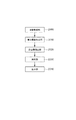
図3は、本画像処理装置の処理動作を示すフローチャートである。 FIG. 3 is a flowchart showing the processing operation of the image processing apparatus.
<調整>
まず、ステップS101において、被検眼を本装置に配置した状態で、本装置と被検眼のアライメントを行う。アライメントの説明に関して、本実施形態に特有な処理について説明し、ワーキングディスタンス等のXYZ方向のアライメント、フォーカス、コヒーレンスゲートの調整等は一般的であるのでその説明は省略する。
<Adjustment>
First, in step S101, the apparatus and the eye to be examined are aligned with the eye to be examined being placed on the apparatus. Regarding the description of the alignment, processing unique to the present embodiment will be described, and alignment in the XYZ directions such as working distance, focus, adjustment of the coherence gate, and the like are common, and description thereof will be omitted.
<撮像>
PS−OCTの撮像中の固視微動または固視不良などによる被検眼の動きは、PS−OCT画像の歪みの原因となる。これを防ぐため、S102のステップではOCTのスキャナの動きを眼の動きに追従させる追尾を行いつつPS−OCTの撮像をしている。
<Imaging>
The movement of the eye to be inspected due to fixation micromotion or fixation failure during PS-OCT imaging causes distortion of the PS-OCT image. In order to prevent this, in step S102, PS-OCT imaging is performed while tracking the movement of the OCT scanner to follow the movement of the eyes.
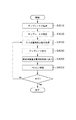
図10はS102(撮像)の詳細な処理の流れを示す図であり、図10の処理の流れに従い、S102の処理を説明する。図10のS4010〜S4050のステップは追尾機能を実現するためのステップである。追尾機能は、追尾制御部195が司っている。 FIG. 10 is a diagram showing a detailed processing flow of S102 (imaging), and the processing of S102 will be described according to the processing flow of FIG. Steps S4010 to S4050 in FIG. 10 are steps for realizing the tracking function. The tracking control unit 195 governs the tracking function.
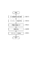
そして図10におけるS4010(テンプレート生成)のステップは、詳細には図11に示される処理の流れに従う。S4010はテンプレートマッチングで用いるテンプレート画像を生成するステップである。 The step of S4010 (template generation) in FIG. 10 follows the processing flow shown in FIG. 11 in detail. S4010 is a step of generating a template image used in template matching.
まずS5010のステップ(SLO眼底輝度画像の取得)は、追尾制御部195はAPD152、153から生成されたSLO眼底輝度画像を、テンプレート生成用に20フレーム取得する。
First, in step S5010 (acquisition of SLO fundus luminance image), the tracking control unit 195 acquires 20 frames of the SLO fundus luminance image generated from the
なお、テンプレート生成用のSLO眼底輝度画像のフレーム数は多いほどS5040で行う画像の平均化によりテンプレート画像の画質が向上し、その結果テンプレートマッチングの精度が向上する。その半面、テンプレート生成用のSLO眼底輝度画像が多いとテンプレート生成にかかる処理時間は増大する。そのため、フレーム数は必要なマッチングの精度と処理速度を勘案して決定すればよいが、OCTの撮影に必要な精度を確保する上では20フレーム以上が好ましい。なお、テンプレート生成用のSLO眼底輝度画像は、異なる時刻に被検眼の眼底を撮像して得た複数の眼底画像の一例である。 Note that as the number of frames of the SLO fundus luminance image for template generation increases, the image quality of the template image is improved by averaging the images performed in S5040, and as a result, the accuracy of template matching is improved. On the other hand, if there are many SLO fundus luminance images for template generation, the processing time required for template generation increases. Therefore, the number of frames may be determined in consideration of necessary matching accuracy and processing speed, but 20 frames or more are preferable in order to ensure the accuracy necessary for OCT imaging. The template generation SLO fundus luminance image is an example of a plurality of fundus images obtained by imaging the fundus of the eye to be examined at different times.
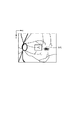
次にS5020(テンプレート位置の指定)のステップでは追尾制御部195がS4010のステップで取得したSLO眼底輝度画像を表示制御部を介して表示部192に表示しテンプレートに使用する画像領域を操作者がマウスを用いてマニュアル指定する。テンプレートの位置を指定する例を図12を用いて示す。図12はSLO眼底輝度画像を示したものであり、領域AAがテンプレート指定領域である。
In step S5020 (designation of template position), the tracking control unit 195 displays the SLO fundus luminance image acquired in step S4010 on the
テンプレート指定領域AAは、パターンマッチングに用いるので血管が分岐している位置などパターンに特徴があるエリア(特徴領域)を選択するのが望ましい。 Since the template designating area AA is used for pattern matching, it is desirable to select an area (feature area) having a pattern feature such as a position where a blood vessel is branched.
なお、テンプレート領域の数は復数であっても良い。また、テンプレート領域の2点以上ある場合にはテンプレートマッチングの結果得られたシフトの量XとYを平均することで、移動量をより精度よく計算することができる。 Note that the number of template regions may be a reversion number. If there are two or more points in the template area, the amount of movement can be calculated more accurately by averaging the shift amounts X and Y obtained as a result of template matching.
なお、テンプレート位置の指定は、追尾制御部195が自動で行っても良い。その際、パターンに特徴のあるエリアを選択するためのアルゴリズムとして、Harrisのコーナー検出アルゴリズムを用いてもよい。 The template position may be specified automatically by the tracking control unit 195. At this time, a Harris corner detection algorithm may be used as an algorithm for selecting an area having a characteristic pattern.
なお、パターンに特徴のあるエリアを選択するためのアルゴリズムとしてMoravecのコーナー検出アルゴリズムやその他のコーナー検出アルゴリズムを用いても良い。復数のテンプレートを選択する場合テンプレートの自動選択により、短時間でパターンに特徴のあるテンプレート位置を選択することができる。 It should be noted that Moravec's corner detection algorithm and other corner detection algorithms may be used as an algorithm for selecting an area with a characteristic pattern. When selecting multiple templates, it is possible to select a template position having a pattern characteristic in a short time by automatic template selection.
次に、S5030(画像の位置合わせ)のステップでは、追尾制御部195がS5010で取得したテンプレート生成用の20フレームの位置ずれ量を計算し、画像パターンの位置合わせをする。追尾制御部195はS5010で取得したある1フレームの画像をテンプレートとし残りの19フレームに対してテンプレート探索する。具体的にはテンプレート画像の位置を変えながら類似度を表す指標であるNormalized Cross−Correlation(NCC)を計算し、この値が最大となるときの画像位置の差を位置ずれ量として求め、20フレームの画像を位置合わせする。 Next, in the step of S5030 (image alignment), the tracking control unit 195 calculates the amount of displacement of 20 frames for template generation acquired in S5010, and aligns the image pattern. The tracking control unit 195 searches for a template for the remaining 19 frames using the image of one frame acquired in S5010 as a template. Specifically, Normalized Cross-Correlation (NCC), which is an index representing the degree of similarity while changing the position of the template image, is calculated, and the difference between the image positions when this value is maximized is obtained as a positional deviation amount, and 20 frames Align the images.
なお、類似度を表す指標は、テンプレートとフレーム内の画像の特徴の類似性を表す尺度であればどのようなものでもよく、例えばSum of Abusolute Difference(SAD)、Sum of Squared Difference(SSD)、Zero−means Normalized Cross−Correlation(ZNCC)等を用いることができる。 The index indicating the similarity may be any scale as long as it represents the similarity between the template and the image feature in the frame. For example, Sum of Absolute Difference (SAD), Sum of Squared Difference (SSD), Zero-means normalized cross-correlation (ZNCC) or the like can be used.
次にS5040(画像平均化)のステップでは、追尾制御部195はS5010にてテンプレート生成用に取得した20フレームの画像について、S5030のステップにより位置合わせを行った画像を平均化する。すなわち、複数の眼底画像の一例であるテンプレート生成用のSLO眼底輝度画像が平均化されることにより、新たな眼底画像が生成される。 Next, in step S5040 (image averaging), the tracking control unit 195 averages the images that have been aligned in step S5030 with respect to the 20-frame image acquired for template generation in S5010. That is, a new fundus image is generated by averaging SLO fundus luminance images for template generation, which is an example of a plurality of fundus images.
次に、S5050のステップでは追尾制御部195はS5040で生成した位置合わせして平均化した画像からS5020で選択したテンプレート位置の情報に基づいて抽出する。すなわち、生成された新たな眼底画像から特徴領域が抽出される。その抽出した画像がテンプレートマッチングに用いるテンプレート画像である。S4010 のステップ、テンプレートの生成の詳細な説明は以上である。 Next, in step S5050, the tracking control unit 195 extracts the template position information selected in step S5020 from the alignment and averaged image generated in step S5040. That is, a feature region is extracted from the generated new fundus image. The extracted image is a template image used for template matching. The detailed description of step S4010 and template generation is as described above.
さらに、図10のS4020(テンプレートの保存)のステップでは追尾制御部195はS4010で生成したテンプレートを記憶部(不図示)に保存する。 Further, in step S4020 (save template) in FIG. 10, the tracking control unit 195 saves the template generated in step S4010 in a storage unit (not shown).
次に、S4030(SLO眼底輝度画像の取得)のステップでは追尾制御部195は眼底移動量算出用にSLO眼底輝度画像を1フレームまたはS5010のステップで取得したフレーム数より少ないフレーム数のSLO眼底輝度画像を取得する。なお、眼底移動量算出用のSLO眼底輝度画像は、複数の眼底画像(テンプレート生成用のSLO眼底輝度画像の一例)よりも少ない数であり且つ該複数の眼底画像とは異なる時刻に被検眼の眼底を撮像して得た少なくとも1つの眼底画像の一例である。 Next, in the step of S4030 (acquisition of SLO fundus luminance image), the tracking control unit 195 performs SLO fundus luminance with a frame number smaller than the number of frames acquired in one frame or the step of S5010 for calculating the fundus movement amount. Get an image. Note that the SLO fundus luminance image for calculating the fundus movement amount is smaller in number than a plurality of fundus images (an example of an SLO fundus luminance image for generating a template) and is different in time from the plurality of fundus images. It is an example of the at least 1 fundus image obtained by imaging the fundus.
なお、眼底移動量算出用のSLO画像は複数取得し重ねあわせて平均化することで画質を向上しても良いが、数を多くするとSLO眼底輝度画像を最初に取得したタイミングからテンプレートマッチングを完了するまでの時間が長くなり、追尾が遅延する。また、眼底移動量算出用のSLO画像を多くすると、テンプレートマッチングの頻度が低下しOCTの位置補正の頻度が低下する(追尾の動作周波数の低下)。そのため、追尾の遅延防止、動作周波数の低下の防止の観点から眼底移動量算出用のSLO画像の数はS5010で取得するテンプレート生成用のフレーム数より少ない方が望ましい。 Note that the image quality may be improved by acquiring multiple SLO images for calculating the fundus movement amount and averaging them together, but if the number is increased, template matching is completed from the timing when the SLO fundus luminance image is first acquired. It takes a long time to do so, and tracking is delayed. Further, if the number of SLO images for calculating the fundus movement amount is increased, the frequency of template matching decreases and the frequency of OCT position correction decreases (decrease in tracking operation frequency). For this reason, it is desirable that the number of SLO images for calculating the fundus movement amount is smaller than the number of frames for template generation acquired in S5010 from the viewpoint of preventing tracking delay and preventing a decrease in operating frequency.
なお、眼底移動量算出用のSLO画像にLow−pass filter(LPF)を適用しても良い。テンプレート画像は、復数の画像を平均化しているため、輝度値の変動が平滑化されている。そのため、眼底移動量算出用のSLO画像も同様にLPFを適用して輝度値の変動を平滑化することでテンプレート画像と眼底移動量算出用のSLO画像の空間周波数を略一致させ、S4040のテンプレート探索の精度を向上することができる。この場合、テンプレート作成時に用いたフレーム数に応じ、LPFの周波数応答が略一致するように、その係数を決定する事が望ましい。 Note that a low-pass filter (LPF) may be applied to the SLO image for calculating the fundus movement amount. Since the template image averages the number of reciprocal images, the fluctuation of the luminance value is smoothed. For this reason, the spatial frequency of the template image and the SLO image for calculating the fundus movement amount are substantially matched by applying the LPF to the SLO image for calculating the fundus movement amount so as to smooth the fluctuation of the luminance value. Search accuracy can be improved. In this case, it is desirable to determine the coefficient according to the number of frames used at the time of creating the template so that the LPF frequency responses substantially match.
次に、S4040(テンプレート探索)のステップでは、追尾制御部195はS4030のステップで取得した眼底移動量算出用のSLO眼底輝度画像からS4020のステップで保存したテンプレート画像を同画像に描出された血管等のパターンを基に探索し眼底移動量を算出する。図13は、眼底移動量算出用のSLO眼底輝度画像を示したものであり、図13を用いて眼底移動量の算出方法を説明する。領域AA‘はテンプレートの指定位置であり図12におけるAAの位置に相当する。領域BBはテンプレート探索の結果の位置である。そしてCCはAA’とBBの位置の差であり、このCCが眼底移動量として算出される。ここで、テンプレート探索の方法はS5030(画像の位置合わせ)で用いたテンプレート探索と同じ方法である。なお、S4040のステップにおいては追尾の遅延を考慮して計算処理量の少ない類似度の指標を求めるのが好ましい。また、眼底移動量としてシフト量XとYに加え回転量θを計算しても良い。 Next, in step S4040 (template search), the tracking control unit 195 displays the template image saved in step S4020 from the SLO fundus luminance image for fundus movement amount acquisition obtained in step S4030 in the same image. The fundus movement amount is calculated by searching based on the pattern. FIG. 13 shows an SLO fundus luminance image for fundus movement amount calculation, and a method for calculating the fundus movement amount will be described with reference to FIG. An area AA ′ is a designated position of the template and corresponds to the position AA in FIG. Area BB is the position of the template search result. CC is the difference between the positions of AA 'and BB, and this CC is calculated as the fundus movement amount. Here, the template search method is the same as the template search used in S5030 (image alignment). In step S4040, it is preferable to obtain a similarity index with a small calculation processing amount in consideration of tracking delay. In addition to the shift amounts X and Y, the rotation amount θ may be calculated as the fundus movement amount.
次に、S4050(眼底移動量を駆動制御部に出力)のステップでは追尾制御部195はS4040で求めた眼底移動量を駆動制御部180に出力する。駆動制御部180は、入力したXとYの2つの移動量から、OCTの撮影位置が常に一定となるようにXスキャナ107、Yスキャナ110を制御する。これにより、被検眼の固視微動や固視不良により移動したとしても常に同じ箇所の断層像を取得することができる。すなわち、抽出された特徴領域と少なくとも1つの眼底画像とに基づいて、上記新たな眼底画像に対応する眼底の第1の偏光断層画像と上記少なくとも1つの眼底画像に対応する眼底の第2の偏光断層画像との位置が補正される。
Next, in step S4050 (output fundus movement amount to drive control unit), tracking control unit 195 outputs the fundus movement amount obtained in S4040 to drive
次に、S4060(PS−OCT測定)のステップでは制御部200は光源101から測定光を出射して、網膜Erからの戻り光を、ラインカメラ129、133で受光する。
Next, in step S4060 (PS-OCT measurement), the
それから撮像を終了するか連続して続けるか操作者が判断し、連続してPS−OCT撮像を続ける場合には追尾制御部195はS4030のステップに戻り、S4030〜S4060のステップを繰り返す。 Then, the operator determines whether to end the imaging or continue continuously. When the PS-OCT imaging is continued continuously, the tracking control unit 195 returns to the step of S4030 and repeats the steps of S4030 to S4060.
被検眼の動きを追尾するためには、PS−SLO140の動作レートがPS−OCT100よりも早いことが望ましい。例えば、PS−OCTのBスキャン取得レートが15Hzの場合、PS−SLOによるSLO眼底輝度画像の取得および処理を含むレートが60Hzであれば1つのBスキャン取得の中で4回の位置補正を行うことが出来る。このため、眼底輝度画像を取得するフレームレートは、60Hz以上が好ましい。
In order to track the movement of the eye to be examined, it is desirable that the operation rate of the PS-
またスキャナによる位置補正においては、撮影領域の中心部分でスキャナの移動による画像の歪が大きくならないようなタイミングで補正することが望ましい。したがって、スキャナ補正がPS−OCTとPS−SLOの取得レートから画像中央部とならないよう、取得レートまたは補正のタイミング調整することが好ましい。 Further, in the position correction by the scanner, it is desirable to correct at a timing at which the distortion of the image due to the movement of the scanner does not increase at the center portion of the photographing region. Therefore, it is preferable to adjust the acquisition rate or the correction timing so that the scanner correction does not become the center of the image from the acquisition rates of PS-OCT and PS-SLO.
なお、高速化のために2つのAPDの中の1つの出力のみを用いてSLO眼底輝度画像の代わりとしてもよいし、図1の構成に替えてPS−SLOの計測光をライン形状として眼底を走査するようにしてもよい。このような構成とすることで、Xスキャナ146による走査は不要となり、高速なSLO眼底輝度画像の取得が可能となる。
In order to increase the speed, only one output of the two APDs may be used instead of the SLO fundus luminance image, or instead of the configuration of FIG. You may make it scan. With such a configuration, scanning by the
なお、本実施例では追尾に用いる画像としてSLO眼底輝度画像を用いているが、SLO輝度画像はP偏光とS偏光の2乗和で得られるため、測定光の偏光情報は用いないので追尾のSLO眼底輝度画像取得時においてはλ/4偏光板113は光路から外した状態でもよい。 In this embodiment, an SLO fundus luminance image is used as an image used for tracking. However, since the SLO luminance image is obtained by the sum of squares of P-polarized light and S-polarized light, the polarization information of the measurement light is not used. At the time of acquiring the SLO fundus luminance image, the λ / 4 polarizing plate 113 may be removed from the optical path.
なお、本実施例ではPS−SLO140の構成として、眼底上で所望の範囲を測定光で走査するための手段としてガルバノスキャナはXスキャナ146とYスキャナ149を用い、測定光の受光手段としてアバランシェフォトダイオード(APD)152、153を用いているが、ガルバノスキャナはYのみとし、測定光の受光手段としてラインセンサーを用いても良い。
In this embodiment, the PS-
<画像生成>
S102において、撮像で網膜Erからの戻り光の信号を画像生成部193に出力し、前述の通り各画像を生成する。
<Image generation>
In S102, the signal of the return light from the retina Er is output to the
<解析>
健常眼の断層画像と比べて疾病眼の断層画像では、病気の影響により断層画像の輝度値が暗くなってしまう場合があり、その影響で網膜層の見落としや誤検出をしてしまう。そのため、ステップS104においては、画像解析部194は、ステップS103で画像生成部193が計算した偏光状態を解消する箇所の情報を用いて網膜の各層を検出する。
<Analysis>
In a tomographic image of a diseased eye as compared with a tomographic image of a normal eye, the luminance value of the tomographic image may become dark due to the influence of the disease, and the retinal layer may be overlooked or erroneously detected. Therefore, in step S104, the
図4は画像解析部194の構成を示す図である。図4において2000は画像生成部193で生成された偏光状態を示す断層画像を取得する取得手段としての画像取得部である。取得手段は、外部のサーバ等から画像を取得するように構成することもできる。
FIG. 4 is a diagram illustrating the configuration of the
3010、2020は抽出手段としての差分画像生成部及び滲出物抽出部である。差分画像生成部3010は、所定の層としての例であるRPEを偏光解消物質の連続性を解析して抽出し偏光状態を示す断層画像から差し引く差分処理をする差分画像生成部である。滲出物抽出部2020は、所定の層を画像から差し引いた後に滲出物等を抽出する。
解析部2030は、滲出物抽出部2020で得られた滲出物の位置や大きさの情報を得る。そして、出力部2040は、処理結果を表示制御部191に出力する。なお、解析部2030及び出力部2040を表示制御部191の内部に構成してもよい。
The
図5はS104の詳細な処理の流れを示す図であり、図5の処理の流れに従いS104の処理の詳細を説明する。 FIG. 5 is a diagram showing the detailed processing flow of S104, and the details of the processing of S104 will be described according to the processing flow of FIG.
画像取得部2000は、異なる時間(時刻)で撮像された偏光状態を示す三次元の断層画像を複数取得する(S2000)。(式4)のDOPUを計算することにより得られたDOUP画像は、網膜層内においてはRPEが偏光状態を解消するため、所定層としてのRPE層の位置を検出することが出来る。ここで、RPEは層構造であるため一定以上の容積を有する塊として存在する。一方で、滲出物等は、逆に、点在する場合が多く、その大きさは、RPE等の層構造と比べて小さい。
The
そこで、差分画像生成部3010は、モルフォルフィルタ等のフィルタ処理で所定範囲の画素値範囲の領域を縮小処理する(S2010)。例えばダイレーション処理を行う。これにより滲出物等は消失する。次に差分画像生成部3010は縮小した画像を逆処理で拡大する。例えばエロージョン処理をする。ここでの逆処理とは縮小量と同等量を拡大する処理をいう。これにより、RPEの層構造を得ることができる。そして、差分画像生成部3010はRPEの層構造を例えば二値化処理して所定値以上の領域をRPE層の領域として記憶する(S2030,S2040)。
Therefore, the difference
次に、差分画像生成部3010は拡大処理した画像を、元の偏光状態を示す断層画像に対して差分処理を行う(S2050)。これによりRPE層以外の偏光を解消する領域を滲出物等として取得(抽出)する(S2060)。そして、偏光が解消されたそれぞれの領域画像及び抽出された滲出物等の領域情報を偏光状態を示す断層画像に関連付けて記憶する。また、偏光状態を示す断層画像には撮影日時を含む撮像時間の情報が関連付けられている。そのため、偏光が解消されたそれぞれの領域画像及び抽出された滲出物等の領域情報を撮撮影時間と関連付けて記憶部に記憶する。
Next, the difference
そして、解析部2030は各画像から得られた滲出物等の偏光を解消する領域の重心の座標を求める。また、滲出物等の偏光を解消する領域の外接領域を求めてこの領域を滲出物等の偏光を解消する領域の面積を大きさとして得る。そして、偏光を解消する領域の重心の座標、滲出物等の偏光を解消する領域の面積を滲出物等の画像、位置情報を撮影時間を含む撮影時間と関連付けて記憶部に記憶する(S2070)。
Then, the
<出力>
次に、生成した各画像及び解析した結果の出力処理ステップS105について説明する。本実施形態おける出力処理は、ステップS104で求めた情報を効果的に表示する。
<Output>
Next, each generated image and the output processing step S105 of the analysis result will be described. The output process in the present embodiment effectively displays the information obtained in step S104.
信号処理部190内の画像生成部193と画像解析部194において、各画像の生成及び解析が終了すると、その結果に基づき、表示制御部191は、出力情報を生成し、表示部192に出力して表示を行う。図6は、表示制御部191が抽出された滲出物等の画像領域を二次元の断層画像と重ねて表示部192に表示している例である。
When the
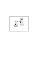
また、解析部2030は、三次元の断層画像を積算処理して平面画像である眼底画像と位置合わせをして、抽出手段で抽出された滲出物等の偏光を解消する領域情報を眼底画像の座標と関連付けて記憶する。そして、表示制御部191は記憶部に記憶される異なる撮像時間に撮像された偏光を解消する領域の画像を平面画像である眼底画像の座標に対応させて変化画像として表示部192に表示する。この場合に、対応する撮影時間毎に表示する色彩を変更して表示部192に表示することで、滲出物等の偏光を解消する領域の時間変化の様子がわかる。更に変化画像に対応する撮影時間を関連付けて表示することでさらに詳細に滲出物等の偏光を解消する領域の時間変化の様子がわかる。また、滲出物等の偏光を解消する領域の撮影時間毎の重心の位置や大きさを合わせて表示部に表示すると大きさや位置の時間変化が理解しやすくなる。図7は異なる撮影時間で撮像された偏光を解消する領域の画像を平面画像の座標に対応させて表示すると共に撮影時間毎の重心の位置や大きさを合わせて表示部した例である。この場合に平面画像である眼底画像に重ね合わせて表示すると眼底画像と対比が容易となる。
Further, the
図8の左上の図は眼底画像を示している、右上の図は、偏光を解消する領域の画像を平面画像の座標に対応させて表示すると共に撮影時間毎の重心の位置や大きさを合わせて表示する変化画像を示している。また、左下の図は偏光を解消する領域の位置としての重心を平面画像の座標と撮影時間に対応させて表示した位置画像である。右下の図は左上図の黄班と滲出物等の偏光を解消する領域(E)を横切る断層像を示している。このように異なる情報を有する画像を並べて表示制御部191が表示部192に表示することで滲出物等の偏光を解消する領域の時間変換を容易に観察することができる。
The upper left figure of FIG. 8 shows the fundus image, and the upper right figure displays the image of the area to be depolarized in correspondence with the coordinates of the planar image and adjusts the position and size of the center of gravity for each shooting time. A change image to be displayed is shown. Further, the lower left figure is a position image in which the center of gravity as the position of the region where polarization is eliminated is displayed in correspondence with the coordinates of the plane image and the photographing time. The lower right figure shows a tomographic image crossing the region (E) where the polarization of the yellow spots and exudates in the upper left figure is eliminated. As described above, when the
(変形例1)
図9は、滲出物等の偏光を解消する領域情報を抽出する変形例の処理の流れを示す図である。
(Modification 1)
FIG. 9 is a diagram showing a flow of processing of a modified example for extracting region information for canceling polarization such as exudates.
画像取得部2000は、異なる時間(時刻)で撮像された偏光状態を示す三次元の断層画像を複数取得する(S3000)。次に、記憶されるRPEの層領域の情報を領域抽出手段は抽出し、三次元の断層画像それぞれからRPEの層領域の情報を除いて所定範囲の画素値範囲を滲出物等の偏光を解消する領域情報として取得する(S3010,S3020)。
The
そして、解析部2030は各画像から得られた滲出物等の偏光を解消する領域の膨張、縮小処理を行う。この処理により滲出物等の偏光を解消する領域がある程度の大きさの領域として抽出される(S3010,S3020)。この領域の重心の座標と大きさを解析部2030は求めて記憶部に記憶する。また、滲出物等の偏光を解消する領域の外接領域を求めてこの領域を滲出物等の偏光を解消する領域の面積を大きさとして得る。そして、偏光を解消する領域の重心の座標、滲出物等の偏光を解消する領域の面積を滲出物等の画像、位置情報を撮影時間を含む撮影時間と関連付けて記憶部に記憶する(S3040)。次に、生成した各画像及び解析した結果を出力する(S3050)。
Then, the
(その他の実施例)
また、本発明は、以下の処理を実行することによっても実現される。即ち、上述した実施形態の機能を実現するソフトウェア(プログラム)を、ネットワーク又は各種記憶媒体を介してシステム或いは装置に供給し、そのシステム或いは装置のコンピュータ(またはCPUやMPU等)がプログラムを読み出して実行する処理である。
(Other examples)
The present invention can also be realized by executing the following processing. That is, software (program) that realizes the functions of the above-described embodiments is supplied to a system or apparatus via a network or various storage media, and a computer (or CPU, MPU, etc.) of the system or apparatus reads the program. It is a process to be executed.
Claims (8)
前記複数の眼底画像を平均化して新たな眼底画像を生成する手段と、
前記生成された新たな眼底画像から特徴領域を抽出する抽出手段と、
前記抽出された特徴領域と前記少なくとも1つの眼底画像とに基づいて、前記新たな眼底画像に対応する前記眼底の第1の偏光断層画像と前記少なくとも1つの眼底画像に対応する前記眼底の第2の偏光断層画像との位置が補正されるように、前記眼底を追尾する手段と、
を有することを特徴とする眼科装置。 A plurality of fundus images obtained by imaging the fundus of the eye to be examined at different times and a number smaller than the plurality of fundus images and the fundus of the eye to be examined at times different from the plurality of fundus images Fundus image acquisition means for acquiring the obtained at least one fundus image;
Means for averaging the plurality of fundus images to generate a new fundus image;
Extraction means for extracting a feature region from the generated new fundus image;
Based on the extracted feature region and the at least one fundus image, a first polarized tomographic image of the fundus corresponding to the new fundus image and a second of the fundus corresponding to the at least one fundus image. Means for tracking the fundus so that the position of the polarization tomographic image is corrected,
An ophthalmologic apparatus comprising:
前記複数の眼底画像を平均化して新たな眼底画像を生成する工程と、
前記生成された新たな眼底画像から特徴領域を抽出する工程と、
前記抽出された特徴領域と前記少なくとも1つの眼底画像とに基づいて、前記新たな眼底画像に対応する前記眼底の第1の偏光断層画像と前記少なくとも1つの眼底画像に対応する前記眼底の第2の偏光断層画像との位置が補正されるように、前記眼底を追尾する工程と、
を有することを特徴とする眼科方法。 A plurality of fundus images obtained by imaging the fundus of the eye to be examined at different times and a number smaller than the plurality of fundus images and the fundus of the eye to be examined at times different from the plurality of fundus images Obtaining at least one fundus image obtained;
Averaging the plurality of fundus images to generate a new fundus image;
Extracting a feature region from the generated new fundus image;
Based on the extracted feature region and the at least one fundus image, a first polarized tomographic image of the fundus corresponding to the new fundus image and a second of the fundus corresponding to the at least one fundus image. Tracking the fundus so that the position of the polarization tomographic image is corrected,
An ophthalmic method characterized by comprising:
前記複数の断層画像から偏光が解消された領域をそれぞれ抽出する抽出手段と、
前記偏光が解消されたそれぞれの領域の情報を関連付けて表示手段に表示させる表示制御手段と、
前記複数の断層画像に対応する複数の平面画像を60Hz以上のフレームレートで取得する平面画像取得手段と、
を有することを特徴とする撮影装置。 Acquisition means for acquiring a plurality of tomographic images indicating polarization states of the subject imaged at different times;
Extraction means for extracting each of the regions from which polarization has been eliminated from the plurality of tomographic images;
Display control means for displaying on the display means in association with the information of each of the regions where the polarization has been eliminated;
Plane image acquisition means for acquiring a plurality of plane images corresponding to the plurality of tomographic images at a frame rate of 60 Hz or more;
A photographing apparatus comprising:
前記複数の断層画像から前記偏光が解消された領域をそれぞれ抽出する工程と、
前記偏光が解消されたそれぞれの領域の情報を関連付けて表示手段に表示させる工程と、
前記複数の断層画像に対応する複数の平面画像を60Hz以上のフレームレートで取得する工程と、
を有することを特徴とする撮影方法。 Acquiring a plurality of tomographic images indicating polarization states of the subject imaged at different times;
Extracting each of the regions where the polarization has been removed from the plurality of tomographic images;
Associating and displaying on the display means the information of the respective areas where the polarization has been eliminated;
Obtaining a plurality of planar images corresponding to the plurality of tomographic images at a frame rate of 60 Hz or higher;
A photographing method characterized by comprising:
Priority Applications (3)
| Application Number | Priority Date | Filing Date | Title |
|---|---|---|---|
| JP2014001524A JP2014155694A (en) | 2013-01-16 | 2014-01-08 | Ophthalmologic apparatus and ophthalmologic method |
| US14/155,222 US9232887B2 (en) | 2013-01-16 | 2014-01-14 | Ophthalmic apparatus and ophthalmic method |
| EP14151390.3A EP2756796B1 (en) | 2013-01-16 | 2014-01-16 | Ophthalmic apparatus and ophthalmic method |
Applications Claiming Priority (3)
| Application Number | Priority Date | Filing Date | Title |
|---|---|---|---|
| JP2013005393 | 2013-01-16 | ||
| JP2013005393 | 2013-01-16 | ||
| JP2014001524A JP2014155694A (en) | 2013-01-16 | 2014-01-08 | Ophthalmologic apparatus and ophthalmologic method |
Publications (2)
| Publication Number | Publication Date |
|---|---|
| JP2014155694A true JP2014155694A (en) | 2014-08-28 |
| JP2014155694A5 JP2014155694A5 (en) | 2017-03-16 |
Family
ID=49943250
Family Applications (1)
| Application Number | Title | Priority Date | Filing Date |
|---|---|---|---|
| JP2014001524A Pending JP2014155694A (en) | 2013-01-16 | 2014-01-08 | Ophthalmologic apparatus and ophthalmologic method |
Country Status (3)
| Country | Link |
|---|---|
| US (1) | US9232887B2 (en) |
| EP (1) | EP2756796B1 (en) |
| JP (1) | JP2014155694A (en) |
Cited By (2)
| Publication number | Priority date | Publication date | Assignee | Title |
|---|---|---|---|---|
| JP2016075585A (en) * | 2014-10-07 | 2016-05-12 | キヤノン株式会社 | Imaging device, noise reduction method of tomographic image, and program |
| JP2019205912A (en) * | 2019-09-03 | 2019-12-05 | キヤノン株式会社 | Ophthalmologic apparatus, image generation method, and program |
Families Citing this family (10)
| Publication number | Priority date | Publication date | Assignee | Title |
|---|---|---|---|---|
| JP6742691B2 (en) * | 2015-01-30 | 2020-08-19 | キヤノン株式会社 | Ophthalmic apparatus, image processing method and program |
| JP6594033B2 (en) * | 2015-05-14 | 2019-10-23 | キヤノン株式会社 | Image processing apparatus, image processing method, and program |
| JP2017080344A (en) * | 2015-10-30 | 2017-05-18 | キヤノン株式会社 | Image processing device, image processing method and optical interference tomographic device |
| US10335026B2 (en) * | 2017-01-11 | 2019-07-02 | Canon Kabushiki Kaisha | Image processing apparatus that generates a tomographic image using an estimation value of pixel values, and related optical coherence tomography apparatus, image processing method, and computer-readable storage medium |
| WO2019076335A1 (en) * | 2017-10-20 | 2019-04-25 | 视微影像(河南)科技有限公司 | Ophthalmic imaging diagnostic system |
| EP3653987A1 (en) * | 2018-11-16 | 2020-05-20 | Nokia Technologies Oy | Apparatus and method for detecting light |
| WO2020106792A1 (en) | 2018-11-21 | 2020-05-28 | University Of Washington | System and method for retina template matching in teleophthalmology |
| JP7199236B2 (en) * | 2019-01-24 | 2023-01-05 | 株式会社トプコン | ophthalmic equipment |
| US11508062B2 (en) | 2019-03-29 | 2022-11-22 | Nidek Co., Ltd. | Ophthalmological image processing apparatus |
| TWI749531B (en) * | 2020-04-22 | 2021-12-11 | 晉弘科技股份有限公司 | Scanning device and system of optical coherence tomography system |
Citations (2)
| Publication number | Priority date | Publication date | Assignee | Title |
|---|---|---|---|---|
| JP2011212103A (en) * | 2010-03-31 | 2011-10-27 | Topcon Corp | Laser scanning type photographing apparatus |
| JP2011229835A (en) * | 2010-04-30 | 2011-11-17 | Canon Inc | Characteristic point extraction method and ophthalmologic apparatus |
Family Cites Families (10)
| Publication number | Priority date | Publication date | Assignee | Title |
|---|---|---|---|---|
| US7758189B2 (en) | 2006-04-24 | 2010-07-20 | Physical Sciences, Inc. | Stabilized retinal imaging with adaptive optics |
| JP2010175448A (en) | 2009-01-30 | 2010-08-12 | Kowa Co | Optical imaging device |
| EP2243420A1 (en) | 2009-04-24 | 2010-10-27 | Schmidt-Erfurth, Ursula | Method for determining exudates in the retina |
| GB0907277D0 (en) | 2009-04-29 | 2009-06-10 | Univ Kent Kanterbury | Method for depth resolved wavefront sensing, depth resolved wavefront sensors and method and apparatus for optical imaging |
| JP5017328B2 (en) * | 2009-08-11 | 2012-09-05 | キヤノン株式会社 | Tomographic imaging apparatus, control method therefor, program, and storage medium |
| EP2563206B1 (en) | 2010-04-29 | 2018-08-29 | Massachusetts Institute of Technology | Method and apparatus for motion correction and image enhancement for optical coherence tomography |
| JP5297415B2 (en) * | 2010-04-30 | 2013-09-25 | キヤノン株式会社 | Ophthalmic device and ophthalmic method |
| US8801178B2 (en) | 2010-11-04 | 2014-08-12 | Nidek Co., Ltd. | Fundus photographing apparatus |
| JP2012161382A (en) | 2011-02-03 | 2012-08-30 | Nidek Co Ltd | Ophthalmological instrument |
| US9433353B2 (en) | 2011-06-23 | 2016-09-06 | Nidek Co., Ltd. | Optical coherence tomography apparatus |
-
2014
- 2014-01-08 JP JP2014001524A patent/JP2014155694A/en active Pending
- 2014-01-14 US US14/155,222 patent/US9232887B2/en not_active Expired - Fee Related
- 2014-01-16 EP EP14151390.3A patent/EP2756796B1/en not_active Not-in-force
Patent Citations (2)
| Publication number | Priority date | Publication date | Assignee | Title |
|---|---|---|---|---|
| JP2011212103A (en) * | 2010-03-31 | 2011-10-27 | Topcon Corp | Laser scanning type photographing apparatus |
| JP2011229835A (en) * | 2010-04-30 | 2011-11-17 | Canon Inc | Characteristic point extraction method and ophthalmologic apparatus |
Cited By (4)
| Publication number | Priority date | Publication date | Assignee | Title |
|---|---|---|---|---|
| JP2016075585A (en) * | 2014-10-07 | 2016-05-12 | キヤノン株式会社 | Imaging device, noise reduction method of tomographic image, and program |
| US10126112B2 (en) | 2014-10-07 | 2018-11-13 | Canon Kabushiki Kaisha | Tomographic image capturing apparatus and method with noise reduction technique |
| JP2019205912A (en) * | 2019-09-03 | 2019-12-05 | キヤノン株式会社 | Ophthalmologic apparatus, image generation method, and program |
| JP7077283B2 (en) | 2019-09-03 | 2022-05-30 | キヤノン株式会社 | Ophthalmic equipment, image generation methods and programs |
Also Published As
| Publication number | Publication date |
|---|---|
| EP2756796B1 (en) | 2017-09-13 |
| US9232887B2 (en) | 2016-01-12 |
| EP2756796A1 (en) | 2014-07-23 |
| US20140198300A1 (en) | 2014-07-17 |
Similar Documents
| Publication | Publication Date | Title |
|---|---|---|
| JP6071331B2 (en) | Image processing apparatus and image processing method | |
| JP5988772B2 (en) | Image processing apparatus and image processing method | |
| JP2014155694A (en) | Ophthalmologic apparatus and ophthalmologic method | |
| JP6184232B2 (en) | Image processing apparatus and image processing method | |
| JP6202924B2 (en) | Imaging apparatus and imaging method | |
| JP6061554B2 (en) | Image processing apparatus and image processing method | |
| JP6143422B2 (en) | Image processing apparatus and method | |
| JP6184231B2 (en) | Image processing apparatus and image processing method | |
| JP6061555B2 (en) | Image processing apparatus and image processing method | |
| JP2014110883A (en) | Image processor and image processing method | |
| JP2014110884A (en) | Image processor and image processing method | |
| US9068812B2 (en) | Imaging apparatus, imaging method, and storage medium | |
| JP2017131550A (en) | Mage processing device and image processing method | |
| JP2014083285A (en) | Image processor and image processing method | |
| JP2016055122A (en) | Optical coherence tomography device, oct analysis processor and program | |
| JP6146951B2 (en) | Image processing apparatus, image processing method, photographing apparatus, and photographing method | |
| JP6381622B2 (en) | Image processing apparatus and image processing method | |
| JP5988883B2 (en) | Image processing apparatus and image processing method | |
| JP6647013B2 (en) | Image processing apparatus, image processing method, and optical coherence tomography apparatus | |
| JP6437055B2 (en) | Image processing apparatus and image processing method | |
| JP2018000687A (en) | Image processing device, image processing method, and program | |
| JP6505072B2 (en) | Image processing apparatus and image processing method | |
| JP2013148509A (en) | Image processing device and image processing method | |
| JP6039185B2 (en) | Imaging device | |
| JP5936368B2 (en) | Optical coherence tomography apparatus and method for operating the same |
Legal Events
| Date | Code | Title | Description |
|---|---|---|---|
| A621 | Written request for application examination |
Free format text: JAPANESE INTERMEDIATE CODE: A621 Effective date: 20170106 |
|
| A521 | Request for written amendment filed |
Free format text: JAPANESE INTERMEDIATE CODE: A523 Effective date: 20170206 |
|
| A977 | Report on retrieval |
Free format text: JAPANESE INTERMEDIATE CODE: A971007 Effective date: 20171027 |
|
| A131 | Notification of reasons for refusal |
Free format text: JAPANESE INTERMEDIATE CODE: A131 Effective date: 20171114 |
|
| A521 | Request for written amendment filed |
Free format text: JAPANESE INTERMEDIATE CODE: A523 Effective date: 20180109 |
|
| A131 | Notification of reasons for refusal |
Free format text: JAPANESE INTERMEDIATE CODE: A131 Effective date: 20180626 |
|
| A02 | Decision of refusal |
Free format text: JAPANESE INTERMEDIATE CODE: A02 Effective date: 20181218 |