JP2014155144A - Audio input unit and noise suppression method - Google Patents
Audio input unit and noise suppression method Download PDFInfo
- Publication number
- JP2014155144A JP2014155144A JP2013025244A JP2013025244A JP2014155144A JP 2014155144 A JP2014155144 A JP 2014155144A JP 2013025244 A JP2013025244 A JP 2013025244A JP 2013025244 A JP2013025244 A JP 2013025244A JP 2014155144 A JP2014155144 A JP 2014155144A
- Authority
- JP
- Japan
- Prior art keywords
- microphone
- noise
- signal
- sound
- input device
- Prior art date
- Legal status (The legal status is an assumption and is not a legal conclusion. Google has not performed a legal analysis and makes no representation as to the accuracy of the status listed.)
- Pending
Links
- 230000001629 suppression Effects 0.000 title claims abstract description 28
- 238000000034 method Methods 0.000 title claims description 37
- 238000012545 processing Methods 0.000 claims abstract description 33
- 230000008569 process Effects 0.000 claims description 17
- 238000001914 filtration Methods 0.000 claims description 6
- 239000000758 substrate Substances 0.000 description 33
- 238000010586 diagram Methods 0.000 description 12
- 230000006870 function Effects 0.000 description 8
- 230000008859 change Effects 0.000 description 7
- 230000002238 attenuated effect Effects 0.000 description 5
- 238000004891 communication Methods 0.000 description 5
- 230000009467 reduction Effects 0.000 description 5
- 230000035945 sensitivity Effects 0.000 description 5
- 239000000853 adhesive Substances 0.000 description 3
- 230000001070 adhesive effect Effects 0.000 description 3
- 230000005236 sound signal Effects 0.000 description 3
- 230000005540 biological transmission Effects 0.000 description 2
- 238000013461 design Methods 0.000 description 2
- 230000010365 information processing Effects 0.000 description 2
- 125000002066 L-histidyl group Chemical group [H]N1C([H])=NC(C([H])([H])[C@](C(=O)[*])([H])N([H])[H])=C1[H] 0.000 description 1
- 230000008901 benefit Effects 0.000 description 1
- 239000003990 capacitor Substances 0.000 description 1
- 238000005516 engineering process Methods 0.000 description 1
- 239000003822 epoxy resin Substances 0.000 description 1
- PCHJSUWPFVWCPO-UHFFFAOYSA-N gold Chemical compound [Au] PCHJSUWPFVWCPO-UHFFFAOYSA-N 0.000 description 1
- 239000010931 gold Substances 0.000 description 1
- 229910052737 gold Inorganic materials 0.000 description 1
- 239000000463 material Substances 0.000 description 1
- 230000007246 mechanism Effects 0.000 description 1
- 238000012986 modification Methods 0.000 description 1
- 230000004048 modification Effects 0.000 description 1
- 229920000647 polyepoxide Polymers 0.000 description 1
- 238000003672 processing method Methods 0.000 description 1
- 230000000644 propagated effect Effects 0.000 description 1
- 238000007789 sealing Methods 0.000 description 1
- 229920002050 silicone resin Polymers 0.000 description 1
Images


Classifications
-
- G—PHYSICS
- G10—MUSICAL INSTRUMENTS; ACOUSTICS
- G10L—SPEECH ANALYSIS TECHNIQUES OR SPEECH SYNTHESIS; SPEECH RECOGNITION; SPEECH OR VOICE PROCESSING TECHNIQUES; SPEECH OR AUDIO CODING OR DECODING
- G10L21/00—Speech or voice signal processing techniques to produce another audible or non-audible signal, e.g. visual or tactile, in order to modify its quality or its intelligibility
- G10L21/02—Speech enhancement, e.g. noise reduction or echo cancellation
- G10L21/0208—Noise filtering
- G10L21/0216—Noise filtering characterised by the method used for estimating noise
- G10L21/0232—Processing in the frequency domain
-
- H—ELECTRICITY
- H04—ELECTRIC COMMUNICATION TECHNIQUE
- H04R—LOUDSPEAKERS, MICROPHONES, GRAMOPHONE PICK-UPS OR LIKE ACOUSTIC ELECTROMECHANICAL TRANSDUCERS; DEAF-AID SETS; PUBLIC ADDRESS SYSTEMS
- H04R1/00—Details of transducers, loudspeakers or microphones
- H04R1/10—Earpieces; Attachments therefor ; Earphones; Monophonic headphones
- H04R1/1083—Reduction of ambient noise
-
- G—PHYSICS
- G10—MUSICAL INSTRUMENTS; ACOUSTICS
- G10L—SPEECH ANALYSIS TECHNIQUES OR SPEECH SYNTHESIS; SPEECH RECOGNITION; SPEECH OR VOICE PROCESSING TECHNIQUES; SPEECH OR AUDIO CODING OR DECODING
- G10L21/00—Speech or voice signal processing techniques to produce another audible or non-audible signal, e.g. visual or tactile, in order to modify its quality or its intelligibility
- G10L21/02—Speech enhancement, e.g. noise reduction or echo cancellation
- G10L21/0208—Noise filtering
- G10L21/0216—Noise filtering characterised by the method used for estimating noise
- G10L2021/02161—Number of inputs available containing the signal or the noise to be suppressed
- G10L2021/02165—Two microphones, one receiving mainly the noise signal and the other one mainly the speech signal
-
- H—ELECTRICITY
- H04—ELECTRIC COMMUNICATION TECHNIQUE
- H04R—LOUDSPEAKERS, MICROPHONES, GRAMOPHONE PICK-UPS OR LIKE ACOUSTIC ELECTROMECHANICAL TRANSDUCERS; DEAF-AID SETS; PUBLIC ADDRESS SYSTEMS
- H04R1/00—Details of transducers, loudspeakers or microphones
- H04R1/10—Earpieces; Attachments therefor ; Earphones; Monophonic headphones
- H04R1/1041—Mechanical or electronic switches, or control elements
-
- H—ELECTRICITY
- H04—ELECTRIC COMMUNICATION TECHNIQUE
- H04R—LOUDSPEAKERS, MICROPHONES, GRAMOPHONE PICK-UPS OR LIKE ACOUSTIC ELECTROMECHANICAL TRANSDUCERS; DEAF-AID SETS; PUBLIC ADDRESS SYSTEMS
- H04R2410/00—Microphones
- H04R2410/05—Noise reduction with a separate noise microphone
-
- H—ELECTRICITY
- H04—ELECTRIC COMMUNICATION TECHNIQUE
- H04R—LOUDSPEAKERS, MICROPHONES, GRAMOPHONE PICK-UPS OR LIKE ACOUSTIC ELECTROMECHANICAL TRANSDUCERS; DEAF-AID SETS; PUBLIC ADDRESS SYSTEMS
- H04R3/00—Circuits for transducers, loudspeakers or microphones
- H04R3/005—Circuits for transducers, loudspeakers or microphones for combining the signals of two or more microphones
Landscapes
- Engineering & Computer Science (AREA)
- Physics & Mathematics (AREA)
- Acoustics & Sound (AREA)
- Signal Processing (AREA)
- Computational Linguistics (AREA)
- Quality & Reliability (AREA)
- Health & Medical Sciences (AREA)
- Audiology, Speech & Language Pathology (AREA)
- Human Computer Interaction (AREA)
- Multimedia (AREA)
- Circuit For Audible Band Transducer (AREA)
- Electrostatic, Electromagnetic, Magneto- Strictive, And Variable-Resistance Transducers (AREA)
Abstract
Description
本発明は、音声入力装置、及び、音声入力装置に適用される雑音抑圧方法に関する。 The present invention relates to a voice input device and a noise suppression method applied to the voice input device.
従来、音声入力が可能であるとともに、入力された音声の信号処理を実行する音声入力装置が知られている。例えば、携帯電話機やヘッドセット等の音声通信機器や、入力された音声を解析する技術を利用した情報処理システム(音声認証システム、音声認識システム、コマンド生成システム、電子辞書、翻訳機、音声入力方式のリモートコントローラ等)、或いは、録音機器等に、音声入力装置が適用されている。 2. Description of the Related Art Conventionally, a voice input device that can input voice and performs signal processing of input voice is known. For example, voice communication devices such as mobile phones and headsets, and information processing systems that use technology to analyze input voices (voice authentication systems, voice recognition systems, command generation systems, electronic dictionaries, translators, voice input methods The audio input device is applied to a remote controller or the like) or a recording device.
このような音声入力装置は、一般に、目的の音源から発せられる音(例えば話者音声)以外に、周囲の騒音や部外者の声といった、遠方で発生した雑音(背景ノイズ)も取り込んでしまう。背景ノイズが取り込まれると、結果的に、例えば、話者音声が通信相手に聞き取り難いといった問題や、誤った音声認識をするといった問題等が発生することがある。 Such a voice input device generally captures noise (background noise) generated in the distance, such as ambient noise and outsider voice, in addition to sound (for example, speaker voice) emitted from a target sound source. . When background noise is taken in, as a result, for example, a problem that it is difficult to hear the speaker's voice from the communication partner, a problem that wrong voice recognition, or the like may occur.
このようなことから、従来、雑音を低減するための種々の手法が開示されている。例えば特許文献1には、検出された雑音レベルに応じて制御信号を形成して雑音低減処理の内容を変化させる構成が開示されている。このような構成では、雑音低減量を適切に調整できるために、より自然な再生音が得られる。
For this reason, various techniques for reducing noise have been disclosed. For example,
特許文献1に開示される雑音低減処理方法では、予め記憶させておいた情報(雑音に関する情報)を用いて雑音低減処理が実行される。このため、例えば、想定外の雑音が取り込まれた場合等に、雑音低減処理が不適切な処理になることが考えられる。また、多量の情報を予め準備して記憶させる作業が必要になるために、作業負担が大きくなることが懸念される。
In the noise reduction processing method disclosed in
以上の点に鑑みて、本発明の目的は、遠方で発生した背景雑音(背景ノイズ)を精度良く抑圧することが可能な音声入力装置、及び、雑音抑圧方法を提供することである。 In view of the above points, an object of the present invention is to provide a voice input device and a noise suppression method capable of accurately suppressing background noise (background noise) generated at a distance.
上記目的を達成するために本発明の音声入力装置は、第1のマイクロホンと、前記第1のマイクロホンに比べて距離減衰率が小さい特性を有する第2のマイクロホンと、前記第1のマイクロホンから得られる第1の信号と前記第2のマイクロホンから得られる第2の信号とを比較して雑音情報を取得し、当該雑音情報に基づいて雑音抑圧処理を行う処理部と、を備える構成(第1の構成)になっている。 In order to achieve the above object, an audio input device of the present invention is obtained from a first microphone, a second microphone having a characteristic that a distance attenuation rate is smaller than that of the first microphone, and the first microphone. A processing unit that compares the first signal obtained with the second signal obtained from the second microphone and obtains noise information and performs noise suppression processing based on the noise information (first Is configured).
本構成によれば、距離減衰率が異なる2種類のマイクロホンから得られる信号を比較することによって雑音情報を取得して、雑音の抑圧を行う構成になっている。このために、雑音を抑圧するために予め準備するデータ量を少なくして、精度良く雑音の抑圧を行うことが可能である。 According to this configuration, noise information is acquired by comparing signals obtained from two types of microphones having different distance attenuation rates, and noise is suppressed. For this reason, it is possible to reduce noise with high accuracy by reducing the amount of data prepared in advance to suppress noise.
上記第1の構成の音声入力装置において、前記雑音情報は、雑音が含まれる周波数に関する情報であり、前記雑音抑圧処理は、前記雑音が含まれる周波数の信号強度を抑圧するようにフィルタ処理を行うことである(第2の構成)のが好ましい。本構成によれば、例えば、高速フーリエ変換処理等を利用して簡単に雑音情報を取得できるとともに、デジタル処理を利用して簡単に雑音の抑圧を図ることができる。 In the voice input device having the first configuration, the noise information is information related to a frequency including noise, and the noise suppression processing performs a filtering process so as to suppress the signal intensity of the frequency including the noise. (Second configuration) is preferable. According to this configuration, for example, noise information can be easily acquired using fast Fourier transform processing or the like, and noise suppression can be easily performed using digital processing.
上記第2の構成の音声入力装置において、前記処理部は、前記第1の信号の信号強度と前記第2の信号の信号強度との差の大きさと、所定の閾値との大小関係を比較して、前記雑音が含まれる周波数を特定する構成(第3の構成)であるのが好ましい。本構成において、前記所定の閾値は、例えば、2種類のマイクロホンの距離減衰特性、及び、これらのマイクロホンの音源からの距離等(その他、例えば誤差を考慮しても良い)を考慮して得ればよく、装置設計の際に適宜決定すればよい。 In the voice input device having the second configuration, the processing unit compares the magnitude of the difference between the signal strength of the first signal and the signal strength of the second signal with a predetermined threshold value. Thus, it is preferable to have a configuration (third configuration) for specifying a frequency including the noise. In the present configuration, the predetermined threshold value can be obtained in consideration of, for example, the distance attenuation characteristics of two types of microphones, the distances of these microphones from the sound source, and the like (in addition, for example, errors may be considered). What is necessary is just to determine suitably at the time of apparatus design.
上記第2又は第3の構成の音声入力装置において、前記フィルタ処理は、前記第1の信号に対して施される構成(第4の構成)であってよい。本構成は、距離減衰特性が大きな第1のマイクロホン(第2のマイクロホンより遠方ノイズを抑圧する性能が大きい)からの信号が、当該音声入力装置に入力された入力音を示す信号として利用される構成であり、接話型の音声入力装置に好適な構成である。 In the voice input device having the second or third configuration, the filtering process may be a configuration (fourth configuration) performed on the first signal. In this configuration, a signal from a first microphone having a large distance attenuation characteristic (a performance of suppressing far-field noise is larger than that of the second microphone) is used as a signal indicating an input sound input to the voice input device. This is a configuration suitable for a close-talking voice input device.
上記第1から第4のいずれかの構成の音声入力装置において、前記第1のマイクロホンは差動マイクロホンであり、前記第2のマイクロホンは無指向性のマイクロホンである構成(第5の構成)であるのが好ましい。本構成によれば、遠方で発生した背景ノイズ(雑音)に対する感度の差を大きくして、雑音の抑圧を図り易い。 In the audio input device having any one of the first to fourth configurations, the first microphone is a differential microphone, and the second microphone is an omnidirectional microphone (fifth configuration). Preferably there is. According to this configuration, it is easy to suppress noise by increasing the difference in sensitivity with respect to background noise (noise) generated in the distance.
上記第5の構成の音声入力装置において、前記第1のマイクロホンは、振動板の一方の面に加わる音圧と他方の面に加わる音圧との差に基づいて前記振動板を振動させて、入力音を電気信号に変換する差動マイクロホンである(第6の構成)のが好ましい。本構成によれば、第1のマイクロホンに必要とされるスペースを小さくし易く、音声入力装置の小型化を図り易い。 In the voice input device having the fifth configuration, the first microphone vibrates the diaphragm based on a difference between a sound pressure applied to one surface of the diaphragm and a sound pressure applied to the other surface, A differential microphone that converts an input sound into an electric signal (sixth configuration) is preferable. According to this configuration, the space required for the first microphone can be easily reduced, and the audio input device can be easily downsized.
上記第1から第6のいずれかの構成の音声入力装置において、前記第1のマイクロホンと前記第2のマイクロホンとが1つのパッケージで構成されている(第7の構成)のが好ましい。本構成によれば、音声入力装置の小型化を図り易い。 In the voice input device having any one of the first to sixth configurations, it is preferable that the first microphone and the second microphone are configured in one package (seventh configuration). According to this configuration, it is easy to reduce the size of the voice input device.
上記目的を達成するために本発明の雑音抑圧方法は、音声入力装置において実行される雑音抑圧方法であって、第1のマイクロホンから得られる第1の信号と、前記第1のマイクロホンに比べて距離減衰率が小さい特性を有する第2のマイクロホンから得られる第2の信号と、の比較によって雑音を含む周波数を特定するステップと、前記雑音を含むと特定された周波数の信号強度を抑圧するフィルタ処理を行うステップと、を備える構成(第8の構成)になっている。 In order to achieve the above object, a noise suppression method of the present invention is a noise suppression method executed in a voice input device, which is compared with a first signal obtained from a first microphone and the first microphone. A step of specifying a frequency including noise by comparison with a second signal obtained from a second microphone having a characteristic with a small distance attenuation rate, and a filter for suppressing the signal intensity of the frequency specified to include the noise And a step of performing processing (eighth configuration).
本構成によれば、距離減衰率が異なる2種類のマイクロホンから得られる信号を比較することによって雑音を含む周波数を特定し、雑音が含むと特定された周波数の信号強度を抑圧して雑音を抑圧する構成になっている。このために、雑音を抑圧するために予め準備するデータ量を少なくして、精度良く雑音の抑圧を行うことが可能である。 According to this configuration, a frequency including noise is specified by comparing signals obtained from two types of microphones having different distance attenuation rates, and noise is suppressed by suppressing the signal intensity of the specified frequency when noise is included. It is configured to do. For this reason, it is possible to reduce noise with high accuracy by reducing the amount of data prepared in advance to suppress noise.
本発明によれば、遠方で発生した背景雑音を精度良く抑圧することが可能な音声入力装置、及び、雑音抑圧方法を提供することができる。 ADVANTAGE OF THE INVENTION According to this invention, the audio | voice input apparatus and noise suppression method which can suppress the background noise generated far away can be provided accurately.
以下、本発明の音声入力装置、及び、雑音抑圧方法の実施形態について図面を参照しながら詳細に説明する。なお、本発明の音声入力装置がヘッドセットに適用される場合を例に、以下説明する。 Hereinafter, embodiments of a voice input device and a noise suppression method of the present invention will be described in detail with reference to the drawings. An example in which the voice input device of the present invention is applied to a headset will be described below.
<ヘッドセットの概略構成>
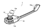
図1は、本発明の実施形態に係るヘッドセット1の外観構成を示す概略斜視図である。ヘッドセット1を構成する筐体10は細長い形状になっており、この筐体10の一端側にスピーカー部12が配置され、他端側にマイク(マイクロホン)部(不図示)が配置される。筐体10のマイク部が配置される側には、マイク部への音の入力を可能とするマイク用音孔10aが2つ形成されている。ヘッドセット1は、スピーカー部12の先端に設けられるイヤーピース12aが人の耳穴に挿入され、マイク用音孔10aが人の口元に配置された状態で使用される。なお、ヘッドセット1は、不図示の装着機構によって人体の一部(耳や頭等)に装着可能になっている。
<Schematic configuration of headset>
FIG. 1 is a schematic perspective view showing an external configuration of a
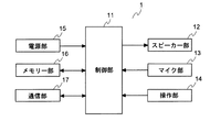
図2は、本発明の実施形態に係るヘッドセット1の構成を示すブロック図である。制御部11は、ヘッドセット1が備える各部を制御して、ヘッドセット1の動作全体を制御する。なお、制御部11は、雑音を抑圧するための一連の処理(詳細は後述する)を実行する。すなわち、制御部11は、本発明の処理部の一例である。
FIG. 2 is a block diagram showing a configuration of the
スピーカー部12は、電気信号を物理振動に変換して音を出力する。マイク部13は入力音を電気信号に変換して出力する。なお、マイク部13の詳細構成については後述する。操作部14は、ユーザーがヘッドセット1を操作するために設けられ、例えば電源スイッチ14a(図1参照)やボリュームスイッチ(不図示)等を含む。電源部15は、ヘッドセット1を動作させるための電力を供給する部分であり、例えば二次電池等で構成される。メモリー部16は、各種の動作用プログラムを格納したり、動作時において種々のデータの一時保存を行ったりする。通信部17は、無線、或いは、有線によって、音声情報を外部に送信したり、外部から受信したりする。
The
<マイク部の詳細構成>
次に、ヘッドセット1が備えるマイク部13の構成について詳細に説明する。図3は、本発明の実施形態に係るヘッドセッド1が備えるマイク部13の外観構成を示す概略斜視図である。図4は、図3に示すマイク部13を裏側から見た場合の概略斜視図である。図3及び図4に示すように、外形略直方体状に形成されるマイク部13(マイクロホンユニット)は、基板部131と、基板部131上に配置される蓋部132と、を備えている。
<Detailed configuration of microphone>
Next, the configuration of the
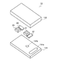
図5は、本発明の実施形態に係るヘッドセッド1が備えるマイク部13の構成を示す分解斜視図である。図6は、図1のA−A位置における概略断面図である。図5及び図6に示すように、平面視略矩形状に設けられる基板部131の長手方向の一端側(図5、6において右端側)には、基板部131を厚み方向に貫く平面視略スタジアム形状(略矩形状)の貫通孔131aが形成されている(図4も参照)。
FIG. 5 is an exploded perspective view showing the configuration of the
また、基板部131の上面(蓋部132が載置される側の面)の略中央部には、平面視略円形状の第1の開口部131bが形成されている。基板部131の下面の長手方向の他端側(貫通孔131aが形成される側とは反対側)には、平面視略スタジアム形状の第2の開口部131cが形成されている(図4も参照)。そして、基板部131の内部には、第1の開口部131bと第2の開口部131cとを連通する基板内部空間131dが形成されている。
A
なお、このような構成の基板部131は、特に限定する趣旨ではないが、複数(例えば3枚)の基板を重ね合わせることによって形成することができる。
The
図5及び図6に示すように、基板部131の上面には、第1の開口部131bを覆うように、第1のMEMS(Micro Electro Mechanical System)チップ21が配置される。また、基板部131の上面には、第1のMEMSチップ21に隣り合うように、第1のASIC(Application Specific Integrated Circuit)22が配置される。基板部131の上面の長手方向の他端側(貫通孔131aが形成される側とは反対側)には、第2のMEMSチップ23が配置される。また、基板部131の上面には、第2のMEMSチップ23に隣り合うように、第2のASIC24が配置される。
As shown in FIGS. 5 and 6, a first micro electro mechanical system (MEMS)
なお、図6に示すように、第1のMEMSチップ21は、振動板21aと、所定間隔をあけて振動板21aと対向配置される固定電極21bとを備えている。すなわち、第1のMEMSチップ21は、コンデンサ型のマイクロホンチップを構成している。同様に、振動板23aと固定電極23bとを備える第2のMEMSチップ23も、コンデンサ型のマイクロホンチップを構成している。第1のASIC22は、第1のMEMSチップ21の静電容量の変化(振動板21aの振動に由来する)に基づいて取り出される電気信号を増幅処理する。また、第2のASIC24は、第2のMEMSチップ23の静電容量の変化(振動板23aの振動に由来する)に基づいて取り出される電気信号を増幅処理する。
As shown in FIG. 6, the
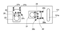
図7は、本発明の実施形態に係るヘッドセット1が備えるマイク部13の基板部131を上から見た場合の概略平面図で、MEMSチップ21、23及びASIC22、24が搭載された状態が示されている。図7を参照して、MEMSチップ21、23及びASIC22、24の電気的な接続関係等について説明しておく。
FIG. 7 is a schematic plan view when the
2つのMEMSチップ21、23及び2つのASIC22、24は、基板部131上にダイボンド材(例えばエポキシ樹脂系やシリコーン樹脂系の接着剤等)を用いて接合されている。なお、2つのMEMSチップ21、23は、音響リークを防止すべく、それらの底面と基板部131の上面との間に隙間が生じないように、基板部131上に接合されている。第1のMEMSチップ21は第1のASIC22に、第2のMEMSチップ23は第2のASIC24に、各々、ワイヤ25(好ましくは金線)によって電気的に接続されている。
The two
第1のASIC22は、ワイヤ25によって基板部131の上面に形成される複数の電極端子26a、26b、26cのそれぞれと電気的に接続されている。電極端子26aは電源電圧(VDD)入力用の電源用端子で、電極端子26bは第1のASIC22で増幅処理された電気信号を出力する第1の出力端子で、電極端子26cはグランド接続用のGND端子である。
The
同様に、第2のASIC23は、ワイヤ25によって基板部131の上面に形成される複数の電極端子27a、27b、27cのそれぞれと電気的に接続されている。電極端子27aは電源電圧(VDD)入力用の電源端子で、電極端子27bは第2のASIC16で増幅処理された電気信号を出力する第2の出力端子で、電極端子27cはグランド接続用のGND端子である。
Similarly, the
電源端子26a、27aは、図示しない配線(貫通配線を含む)を介して、基板部131の下面に設けられる外部接続用の電源パッド28a(図4及び図6参照)に電気的に接続されている。第1の出力端子26bは、図示しない配線(貫通配線を含む)を介して、基板部131の下面に設けられる外部接続用の第1の出力パッド28b(図4及び図6参照)に電気的に接続されている。第2の出力端子27bは、図示しない配線(貫通配線を含む)を介して、基板部131の下面に設けられる外部接続用の第2の出力パッド28c(図4参照)に電気的に接続されている。GND端子26c、27cは、図示しない配線(貫通配線を含む)を介して、基板部131の下面に設けられる外部接続用のGNDパッド28d(図4参照)に電気的に接続されている。
The
なお、基板部131の下面には、貫通孔131a及び第2の開口部131cを取り囲むように、シーリング用パッド28e(図4参照)が設けられている。これは、マイク部13が、ヘッドセット1の筐体10内に配置される実装基板(不図示)に実装される場合に、音響リークを防止すべく利用されるものである。
A
図6に戻って、2つのMEMSチップ21、23及び2つのASIC22、24が搭載された基板部131上に、凹部空間132aが設けられた蓋部132が配置される(被せられる)ことによって、マイク部13が得られる。なお、蓋部132は、例えば接着剤や接着シート等を利用して、音響リークが生じないように基板部131上に接合される。また、マイク部13は、不図示の実装基板(音を通過させる音孔が形成されている)に実装された状態で、ヘッドセット1の筐体10内に配置される。
Returning to FIG. 6, the
図6に示すように、マイク部13においては、外部から(ヘッドセット1のマイク用音孔10a、及び、実装基板の音孔を介して)入力された音波は、貫通孔131a及び第2の開口部131cを介して、その内部に伝搬される。貫通孔131aから入力された音波は、蓋部132の凹部空間132a内を伝搬して、第1のMEMSチップ21の振動板21aの上面に至るとともに、第2のMEMSチップ23の振動板23aの上面に至る。また、第2の開口部131cから入力された音波は、基板内部空間131d及び第1の開口部131bを伝搬して、第1のMEMSチップ21の振動板21aの下面に至る。
As shown in FIG. 6, in the
なお、第1のMEMSチップ21の固定電極21bには複数の貫通孔が形成されており、音波は固定電極21bを通過可能になっている。また、以下では、その機能に注目して、貫通孔131aのことを第1の音孔、第2の開口部131cのことを第2の音孔と表現する。
A plurality of through holes are formed in the fixed
図8は、本発明の実施形態に係るヘッドセット1が備えるマイク部13の構成を示すブロック図である。図8に示すように、第1のASIC22は、第1のMEMSチップ21にバイアス電圧を印加するチャージポンプ回路221を備える。チャージポンプ回路221は、外部(実装基板)から供給される電源電圧(VDD;例えば1.5〜3V程度)を昇圧(例えば6〜10V程度)して、第1のMEMSチップ21にバイアス電圧を印加する。また、第1のASIC22は、第1のMEMSチップ21における静電容量の変化を検出するアンプ回路222を備える。アンプ回路222で増幅された電気信号は、外部(実装基板)へと出力(OUT1)される。
FIG. 8 is a block diagram showing a configuration of the
同様に、第2のASIC24も第2のMEMSチップ23にバイアス電圧を印加するチャージポンプ回路241と、静電容量の変化を検出して増幅された電気信号を出力(OUT2)するアンプ回路242とを備える。なお、2つのアンプ回路222、242のアンプゲインは、適宜設定すればよく、異なるゲイン設定であってよい。
Similarly, the
マイク部13の外部で音が発生すると、第1の音孔131aから入力された音波が第1の音道29を通って第1のMEMSチップ21の振動板21aの上面に到達する。また、第2の音孔131cから入力された音波が第2の音道30を通って第1のMEMSチップ21の振動板21aの下面に到達する(図6も参照)。振動板21aは、その上面に加わる音圧と下面に加わる音圧との音圧差によって振動し、当該振動の発生により、第1のMEMSチップ21において静電容量の変化が生じる。第1のMEMSチップ21の静電容量の変化に基づいて取り出された電気信号は、第1のASIC22のアンプ回路222によって増幅処理されて、最終的に第1の出力パッド28bから出力される。
When sound is generated outside the
また、マイク部13の外部で音が発生すると、第1の音孔131aから入力された音波が第1の音道29を通って第2のMEMSチップ23の振動板23aの上面に到達する(図6も参照)。これによって振動板23aが振動し、当該振動の発生により、第2のMEMSチップ23において静電容量の変化が生じる。第2のMEMSチップ23の静電容量の変化に基づいて取り出された電気信号は、第2のASIC24のアンプ回路242によって増幅処理されて、最終的に第2の出力パッド28cから出力される。
Further, when sound is generated outside the
以上からわかるように、マイク部13においては、第1のMEMSチップ21を用いて得られる信号と、第2のMEMSチップ23を用いて得られる信号とが、別々に外部へと出力される。換言すると、マイク部13は、1パッケージの中に2つのマイクロホンを含む構成になっている。そして、第1のMEMSチップ21を利用した第1のマイクロホン(本発明の第1のマイクロホンに相当)と、第2のMEMSチップ23を利用した第2のマイクロホン(本発明の第2のマイクロホンに相当)とでは、次のような特性の違いを有する。
As can be seen from the above, in the
2つのマイクロホンの特性差を説明するに先立って、音波の性質について簡単に説明しておく。図9は、音圧と音源からの距離との関係を示すグラフである。図9に示すように、音波が空気等の媒質中を進行するにつれて、音圧(音波の強度・振幅)は減衰する。音圧は音源からの距離に反比例し、音圧Pと距離Rとの関係は以下の式(1)のように表せる。なお、式(1)におけるkは比例定数である。
P=k/R (1)
Prior to explaining the difference in characteristics between the two microphones, the nature of the sound wave will be briefly explained. FIG. 9 is a graph showing the relationship between the sound pressure and the distance from the sound source. As shown in FIG. 9, the sound pressure (sound wave intensity / amplitude) is attenuated as the sound wave travels through a medium such as air. The sound pressure is inversely proportional to the distance from the sound source, and the relationship between the sound pressure P and the distance R can be expressed as the following equation (1). In addition, k in Formula (1) is a proportionality constant.
P = k / R (1)
図9及び式(1)から明らかなように、音圧は音源に近い位置では急激に減衰し、音源から離れるほどなだらかに減衰する。このことから、2つの位置間の距離が同じ(Δd)であっても、音源から距離が小さい位置では2つの位置(R1とR2)の間で音圧が大きく減衰し、音源からの距離が大きい位置では2つの位置(R3とR4)の間で音圧があまり減衰しないことがわかる。 As is clear from FIG. 9 and Equation (1), the sound pressure is rapidly attenuated at a position close to the sound source, and gradually attenuates as the distance from the sound source is increased. Therefore, even if the distance between the two positions is the same (Δd), the sound pressure is greatly attenuated between the two positions (R1 and R2) at the position where the distance from the sound source is small, and the distance from the sound source is It can be seen that the sound pressure does not attenuate much between the two positions (R3 and R4) at a large position.
図10は、第1のMEMSチップ21を利用した第1のマイクロホンの指向特性を示す模式図である。なお、図10においては、マイク部13の姿勢は、図6に示す姿勢と同一であることを想定している。音源から振動板21aまでの距離が一定であれば、音源が0°又は180°の方向にある時に振動板21aに加わる音圧が最大となる。これは、音波が第1の音孔131aから振動板21aの上面に至る距離と、音波が第2の音孔131cから振動板21aの下面へと至る距離との差が最も大きくなるからである。
FIG. 10 is a schematic diagram showing the directivity characteristics of the first microphone using the
これに対し、音源が90°又は270°の方向にある時に振動板21aに加わる音圧が最小(0)になる。これは、音波が第1の音孔131aから振動板21aの上面に至る距離と、音波が第2の音孔131cから振動板21aの下面へと至る距離との差がほぼ0となるからである。すなわち、第1のマイクロホンは、0°及び180°の方向から入射される音波に対して感度が高く、90°及び270°の方向から入射される音波に対して感度が低い両指向性を示す。
On the other hand, the sound pressure applied to the
図11は、第2のMEMSチップ23を利用した第2のマイクロホンの指向特性を示す模式図である。なお、図11においては、マイク部13の姿勢は、図6に示す姿勢と同一であることを想定している。音源から振動板23aまでの距離が一定であれば、音源がどの方向にあっても振動板23aに加わる音圧は一定となる。これは、第2のMEMSチップ23が、1つの音孔131aから入力される音波を振動板23aの上面のみで受ける構成になっていることに由来する。すなわち、第2のマイクロホンは、あらゆる方向から入射される音波を均等に受ける無指向性を示す。
FIG. 11 is a schematic diagram showing the directivity characteristics of the second microphone using the
図12は、第1のマイクロホン及び第2のマイクロホンの距離減衰特性を示すグラフである。なお、図12のグラフにおいて、横軸は音源からの距離であり、縦軸はゲイン(マイク出力)である。また、図12は250Hzの音の特性を示している。 FIG. 12 is a graph showing distance attenuation characteristics of the first microphone and the second microphone. In the graph of FIG. 12, the horizontal axis is the distance from the sound source, and the vertical axis is the gain (microphone output). FIG. 12 shows the characteristics of a 250 Hz sound.
第1のMEMSチップ21では、振動板21aは両面(上面及び下面)に加わる音圧の差によって振動する。一方、第2のMEMSチップ23では、振動板23aは一方の面(上面)に加わる音圧によって振動する。第2のMEMSチップ23では、音圧レベルは距離に反比例(1/R;Rは距離)して減衰する。一方、第1のMEMSチップ21では、音圧レベルは1/R2で減衰する。このために、図12に示すように、第2のMEMSチップ23を利用した第2のマイクロホンに比べて、第1のMEMSチップ21を利用した第1のマイクロホンでは、音源からの距離に対するゲイン(信号強度)の低下率が急となる。別の言い方をすると、第2のマイクロホンは、第1のマイクロホンに比べて距離減衰率が小さい特性を有する。
In the
上述のような距離減衰特性を有するために、第1のMEMSチップ21を利用した第1のマイクロホン(差動マイクロホン)は、当該マイクロホンの近傍で発生する音を効率よく収音し、背景ノイズを収音し難い。すなわち、第1のマイクロホンは、いわゆる近接マイクとして機能する。一方、第2のMEMSチップ23を利用した第2のマイクロホンは、当該マイクロホンから遠く離れた位置に音源がある音についても広く収音する性質を有する。
In order to have the above-described distance attenuation characteristics, the first microphone (differential microphone) using the
第1のマイクロホンの特性について、更に説明する。第1のマイクロホン(マイク部13)の近傍で発生する目的音の音圧は、第1の音孔131aと第2の音孔131cとの間で大きく減衰する。このために、第1のマイクロホンの近傍で発生する目的音の音圧については、振動板21aの上面における音圧と、その下面における音圧との間で大きな差が生じる。一方、背景ノイズは、目的音に比べて音源が遠い位置にあるために、第1の音孔131aと第2の音孔131cとの間での減衰は小さい。このために、背景ノイズについては、振動板21aの上面における音圧と、その下面における音圧との差は小さくなる。なお、ここでは、音源から第1の音孔131aまでの距離と、音源から第2の音孔131cまでの距離とが異なる場合を前提としている。
The characteristics of the first microphone will be further described. The sound pressure of the target sound generated in the vicinity of the first microphone (microphone unit 13) is greatly attenuated between the
振動板21aにて受音される背景ノイズの音圧差は小さいために、背景ノイズの音圧は振動板21aにてほぼ打ち消される。これに対して、振動板21aにて受音される上記目的音の音圧差は大きいために、上記目的音の音圧は振動板21aで打ち消されない。このため、第1のMEMSチップ21を利用した第1のマイクロホンは、その近傍で発生する目的音について、背景ノイズを低減して収音する機能に優れることになる。
Since the sound pressure difference of the background noise received by the
以上のようなマイク特性を考慮して、ヘッドセット1(接話型の音声入力装置)においては、第1のMEMSチップ21を利用した第1のマイクロホン(近接マイク)から出力される信号が、基本的に話者音声の音声信号であるものとして利用される。ただし、第1のマイクロホンにおいても、背景ノイズが完全にカットされる訳ではない。そこで、第1のマイクロホンから出力される信号に含まれる背景ノイズ成分を更に抑圧できるように、第2のMEMSチップ23を利用した第2のマイクロホンが利用される構成になっている。以下、ヘッドセット1に備えられる雑音抑圧機能について説明する。
In consideration of the microphone characteristics as described above, in the headset 1 (close-talking voice input device), the signal output from the first microphone (proximity microphone) using the
<雑音抑圧機能>
図13は、本発明の実施形態に係るヘッドセット1において実行される雑音抑圧機能の概要を説明するための模式図である。ヘッドセット1においては、マイク部13はユーザー(話者)の口元(音源)からの距離が所定の近距離(例えば25〜100mmの範囲内の所定の距離等)となることを狙って設計される。当該所定の距離にマイク部13が配置される場合、第1のMEMSチップ21を利用した第1のマイクロホンと、第2のMEMSチップ23を利用した第2のマイクロホンとでは、上述した距離減衰特性の違いによって、所定のゲイン差(信号強度差)が生じる(図13のΔGが該当)。
<Noise suppression function>
FIG. 13 is a schematic diagram for explaining the outline of the noise suppression function executed in the
話者の音声とは別に発生する背景ノイズは比較的遠方で生じる(例えば、マイク位置から250mm以上の遠方等)。上述のように、第1のマイクロホンと第2のマイクロホンとでは、遠方で発生した背景ノイズに対する感度が大きく異なる。すなわち、第1のマイクロホンに比べて第2のマイクロホンの方が、背景ノイズに対する感度がかなり良い。このために、背景ノイズが生じた場合、第1のマイクロホンと第2のマイクロホンとのゲイン差(Δg)は上述のΔGよりも大きくなる。 Background noise generated separately from the speaker's voice occurs relatively far away (for example, far away from the microphone position by 250 mm or more). As described above, the first microphone and the second microphone have greatly different sensitivities to background noise generated in the distance. That is, the sensitivity of the second microphone to background noise is considerably better than that of the first microphone. For this reason, when background noise occurs, the gain difference (Δg) between the first microphone and the second microphone becomes larger than the above-described ΔG.
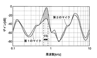
図14は、本発明の実施形態に係るヘッドセット1のマイク部13に背景ノイズを含む音声が入力された場合に得られる信号を模式的に示したグラフである。図14において、横軸(対数軸)は周波数であり、縦軸はゲイン(マイク出力)である。図14に示すように、背景ノイズが発生した場合、第1のマイクロホンと第2のマイクロホンとのゲイン値(信号強度)の差分(Δg)が、ΔGよりも大きくなる周波数帯域が生じる。すなわち、周波数毎に第1のマイクロホンと第2のマイクロホンとのゲイン値の差分(Δg)を求め、当該ΔgがΔGより大きくなるか否かを判定することによって、背景ノイズが含まれる周波数帯域を特定できる。
FIG. 14 is a graph schematically showing a signal obtained when sound including background noise is input to the
ただし、実際には、例えば音源(話者の口元)からマイク部13の位置までの距離は多少の誤差を含むものと考えられる。このために、当該誤差等と、距離減衰特性(図12に例示される)と、を考慮して決められた許容値αを含めて閾値を決定するのが好ましい。すなわち、以下の式(2)を満足する場合に、背景ノイズが発生しているものと判断するのが好ましい。
Δg≧ΔG+α (2)
However, in practice, for example, the distance from the sound source (speaker's mouth) to the position of the
Δg ≧ ΔG + α (2)
なお、許容値αは、ユーザーが選択できるようにしてもよい。ユーザーの中には、例えばできるだけ自然な音で音声を聞きたい等の理由で、背景ノイズの抑圧が不要であると考える者もいれば、背景ノイズを徹底的に除去して欲しいと考える者もいる。許容値αについて、複数段階用意しておくことで、ユーザーの多様なニーズに応え易くなる。 The allowable value α may be selectable by the user. Some users think that suppression of background noise is not necessary, for example, because they want to listen to the sound with as natural a sound as possible, while others want to remove background noise thoroughly. Yes. By preparing a plurality of stages for the allowable value α, it becomes easy to meet various needs of users.
図15は、第1のマイクロホン及び第2のマイクロホンの周波数特性を示すグラフである。なお、図15に示すグラフにおいて、横軸(対数軸)は周波数であり、縦軸はゲイン(マイク出力)である。また、図15は音源からの距離が25mm位置の特性を示している。 FIG. 15 is a graph showing frequency characteristics of the first microphone and the second microphone. In the graph shown in FIG. 15, the horizontal axis (logarithmic axis) is frequency, and the vertical axis is gain (microphone output). FIG. 15 shows the characteristic at a distance of 25 mm from the sound source.
図15からわかるように、正確には、上述のΔGは周波数によって変動する。このために、上述の背景ノイズが発生している周波数帯域を特定する手法は、例えば、ΔGがほぼ変動しない範囲(図15では、例えば100Hz〜数kHz程度であるが、この範囲はマイクの設計で変動可能である)で使用するようにしてもよい。また、これとは別に、上述の背景ノイズが発生している周波数帯域を特定する手法は、音波の周波数値に依存して閾値(例えば式(2)で表される)を決定するΔGを変動させる構成を採用して適用するようにしてもよい。 As can be seen from FIG. 15, the above-described ΔG varies with frequency. For this reason, the above-described method for identifying the frequency band in which background noise occurs is, for example, a range in which ΔG does not substantially vary (in FIG. 15, for example, about 100 Hz to several kHz, but this range is the design of the microphone. It is possible to use it in the above case. In addition to this, the above-described method for identifying the frequency band in which background noise is generated varies ΔG that determines a threshold value (for example, expressed by Expression (2)) depending on the frequency value of the sound wave. You may make it apply and adopt the structure to make.
背景ノイズが発生している周波数帯域が特定できた場合、当該周波数帯域の信号を除去する、或いは、信号強度を低減する処理を行えば、雑音の抑圧を行える。このため、本実施形態では、制御部11(図2参照)は、特定された周波数帯域(複数あってもよい)に対してフィルタ処理(デジタルフィルタ処理)を施せるように構成されている。 When a frequency band in which background noise is generated can be identified, noise can be suppressed by removing a signal in the frequency band or reducing the signal intensity. For this reason, in this embodiment, the control part 11 (refer FIG. 2) is comprised so that a filter process (digital filter process) can be performed with respect to the specified frequency band (a plurality may be sufficient).
図16は、本発明の実施形態に係るヘッドセット1によって実行される雑音抑圧方法の流れを示すフローチャートである。本実施形態の雑音抑圧方法は、マイク部13で音信号(音声)を取得することによって開始される(ステップS1)。マイク部13には、第1のMEMSチップ21を利用した第1のマイクロホンと、第2のMEMSチップ23を利用した第2のマイクロホンとが含まれるために、この両者によって音信号が取得されることになる。
FIG. 16 is a flowchart showing the flow of the noise suppression method executed by the
第1のマイクロホンから出力される信号と、第2のマイクロホンから出力される信号とは、いずれも制御部11(図2参照)に出力される。そして、制御部11は、各信号に対して高速フーリエ変換(FFT)処理を実行する(ステップS2)。この信号処理によって、例えば図17に示すような結果が得られる。図17は、本発明の実施形態に係るヘッドセット1が備えるマイク部13によって取得された信号をFFT処理した結果の一例である。図17において、横軸(対数軸)は周波数であり、縦軸はゲイン(マイク出力)である。
The signal output from the first microphone and the signal output from the second microphone are both output to the control unit 11 (see FIG. 2). And the
なお、本実施形態においては、第1のマイクロホンから出力される信号と、第2のマイクロホンから出力される信号とにFFT処理が実行される構成になっているが、この処理は、離散フーリエ変換(DFT)処理であっても構わない。第1のマイクロホンから出力される信号をFFT(或いはDFT)処理して得られた第1の信号は、本発明の第1の信号に相当する。また、第2のマイクロホンから出力される信号をFFT(或いはDFT)処理して得られた第2の信号は、本発明の第2の信号に相当する。 In this embodiment, the FFT processing is performed on the signal output from the first microphone and the signal output from the second microphone. This processing is performed by discrete Fourier transform. (DFT) processing may be used. The first signal obtained by performing FFT (or DFT) processing on the signal output from the first microphone corresponds to the first signal of the present invention. Further, the second signal obtained by subjecting the signal output from the second microphone to FFT (or DFT) processing corresponds to the second signal of the present invention.
FFT(或いはDFT)処理を実行すると、制御部11は、各周波数において、第1の信号と第2の信号とを比較する。詳細には、制御部11は、各周波数について、第1の信号と第2の信号との間の信号強度の差(Δg;絶対値)を算出する(ステップS3)。そして、制御部11は、得られた信号強度の差(Δg)から、上述の式(2)(Δg≧ΔG+α)を満たす周波数が存在するか否かを確認する(ステップS4)。
When the FFT (or DFT) process is executed, the
上述の式(2)を満たす周波数が存在する場合(ステップS4でYes)、制御部11は、当該周波数には雑音が含まれると判断(特定)する。図17に示す例では、斜線を施して示した範囲が、雑音が含まれる周波数帯域に相当する。制御部11は、第1の信号における雑音を含む周波数帯域(FR)に対してフィルタ処理を施し、当該周波数帯域の信号を除去する、或いは、信号強度を低減する(ステップS5)。
When there is a frequency that satisfies the above-described equation (2) (Yes in step S4), the
フィルタ処理を実行すると、制御部11は、通信部17を制御してフィルタ処理後の信号を送信先(ヘッドセット1と通信を行う相手方)に送信する(ステップS6)。なお、上述の式(2)を満たす周波数が存在しない場合(ステップS4でNo)には、制御部11は第1のマイクロホンに入力された音信号に雑音が含まれないと判断する。このために、ステップS5のフィルタ処理を行うことなく、信号(第1の信号)を送信先に送信する。
When the filter process is executed, the
ここで、フィルタ処理について、もう少し詳しく説明しておく。図18は、本発明の実施形態に係る雑音抑圧方法において実行されるフィルタ処理の一例を説明するための図である。図18に示すように、雑音が含まれる周波数帯域FRに対して施されるフィルタ処理の波形は矩形波であっても構わない。矩形波の信号強度を調整することによって、雑音を抑圧するレベルを調整できる。 Here, the filtering process will be described in a little more detail. FIG. 18 is a diagram for explaining an example of filter processing executed in the noise suppression method according to the embodiment of the present invention. As shown in FIG. 18, the waveform of the filter processing applied to the frequency band FR including noise may be a rectangular wave. The level for suppressing noise can be adjusted by adjusting the signal strength of the rectangular wave.
図19は、本発明の実施形態に係る雑音抑圧方法において実行されるフィルタ処理の他の例を説明するための図である。図19に示すように、雑音が含まれる周波数帯域FRに対して施されるフィルタ処理の波形は矩形波でなくても構わない。例えば、フィルタ処理の波形は、第1の信号(第1のマイクロホンから得られる信号)と、第2の信号(第2のマイクロホンから得られる信号)との差の大きさから見積もられる背景ノイズの大きさに対応して決められるものであっても構わない。このようにすることで、ヘッドセット1から送信される音声について、ユーザーが自然な音と感じることが期待できる。
FIG. 19 is a diagram for explaining another example of the filter process executed in the noise suppression method according to the embodiment of the present invention. As shown in FIG. 19, the waveform of the filter processing applied to the frequency band FR including noise may not be a rectangular wave. For example, the waveform of the filter processing is the background noise estimated from the magnitude of the difference between the first signal (the signal obtained from the first microphone) and the second signal (the signal obtained from the second microphone). It may be determined according to the size. By doing so, it can be expected that the user feels the sound transmitted from the
なお、フィルタ処理の波形については、複数種類の構成を用意しておき、ユーザーが選択できるようにしても構わない。これによって、ユーザーは自身の好みに合った状態でヘッドセット1を使用可能になる。
Note that a plurality of types of configurations may be prepared for the filter processing waveform so that the user can select them. As a result, the user can use the
本実施形態のヘッドセット1は、以上に説明したような雑音抑圧機能(マイクで収音した音声に含まれる雑音を抑圧する機能)を備える。このために、本実施形態のヘッドセット1においては、予め多数の雑音パターンを記憶させることなく、背景ノイズを精度良く除去することが可能である。
The
<その他>
以上に示した実施形態は本発明の例示であり、本発明の適用範囲は、以上に示した実施形態の構成に限定されるものではない。本発明の技術思想を超えない範囲で、以上の実施形態は適宜変更されてよいのは勿論である。
<Others>
The embodiment described above is an exemplification of the present invention, and the scope of application of the present invention is not limited to the configuration of the embodiment described above. Of course, the above embodiments may be modified as appropriate without departing from the technical idea of the present invention.
例えば、以上に示したマイク部13の構成は一例に過ぎず、種々の変形が可能である。例えば、以上においては、マイク部13が備える音孔131a、131cが基板部131側に設けられる構成としたが、例えばマイク部13が備える音孔は蓋部132側に設けられる構成であっても構わない。
For example, the configuration of the
また、以上においては、マイク部13が、1つのパッケージ内に第1のマイクロホン(近接マイク)と第2のマイクロホン(無指向性マイク)とを含むように構成された。しかし、第1のマイクロホンと第2のマイクロホンとは、1つのパッケージ内に構成される必要はなく、別々に構成されてもよい。
In the above, the
また、以上においては、差動マイクホンとして構成される第1のマイクロホンは、1つの振動板の両面に加わる音圧差に基づいて振動板を振動させて、入力音を電気信号に変換する構成とした。しかし、差動マイクロホンとして構成される第1のマイクロホンは、複数の振動板を備える構成であっても構わない。 In the above, the first microphone configured as a differential microphone is configured to vibrate the diaphragm based on the sound pressure difference applied to both surfaces of one diaphragm and convert the input sound into an electrical signal. . However, the first microphone configured as a differential microphone may be configured to include a plurality of diaphragms.
また、以上においては、背景ノイズが発生した場合にフィルタ処理される信号が、第1のマイクロホン(近接マイク)から得られる信号である構成とした。しかし、本発明は、この構成に限定されず、場合によっては、背景ノイズが発生した場合にフィルタ処理される信号は、第2のマイクロホン(無指向性マイク)から得られる信号であってもよい。 In the above description, the signal that is filtered when background noise occurs is a signal obtained from the first microphone (proximity microphone). However, the present invention is not limited to this configuration, and in some cases, the signal to be filtered when background noise occurs may be a signal obtained from the second microphone (omnidirectional microphone). .
また、以上においては、本発明がヘッドセットに適用される場合を示したが、本発明は、ヘッドセットに限らず、携帯電話機等の他の音声通信機器や、情報処理システム(音声認証システム、翻訳機等)、録音機器等に適用されても構わない。 In the above, the case where the present invention is applied to a headset has been described. However, the present invention is not limited to a headset, and other voice communication devices such as a mobile phone, information processing system (voice authentication system, It may be applied to a translator, etc.) and a recording device.
1 ヘッドセット(音声入力装置)
11 制御部(処理部)
13 マイク部(第1のマイクロホン及び第2のマイクロホンを含む)
21 第1のMEMSチップ(第1のマイクロホンを構成する)
23 第2のMEMSチップ(第2のマイクロホンを構成する)
21a 振動板
1 Headset (voice input device)
11 Control unit (processing unit)
13 Microphone unit (including the first microphone and the second microphone)
21 First MEMS chip (constituting the first microphone)
23 Second MEMS chip (constituting the second microphone)
21a Diaphragm
Claims (8)
前記第1のマイクロホンに比べて距離減衰率が小さい特性を有する第2のマイクロホンと、
前記第1のマイクロホンから得られる第1の信号と前記第2のマイクロホンから得られる第2の信号とを比較して雑音情報を取得し、当該雑音情報に基づいて雑音抑圧処理を行う処理部と、
を備えることを特徴とする音声入力装置。 A first microphone;
A second microphone having a characteristic that the distance attenuation rate is smaller than that of the first microphone;
A processing unit that compares the first signal obtained from the first microphone with the second signal obtained from the second microphone to obtain noise information, and performs noise suppression processing based on the noise information; ,
A voice input device comprising:
前記雑音抑圧処理は、前記雑音が含まれる周波数の信号強度を抑圧するようにフィルタ処理を行うことであることを特徴とする請求項1に記載の音声入力装置。 The noise information is information related to a frequency including noise,
The voice input device according to claim 1, wherein the noise suppression process is a filter process so as to suppress a signal intensity of a frequency including the noise.
前記第2のマイクロホンは無指向性のマイクロホンであることを特徴とする請求項1から4のいずれかに記載の音声入力装置。 The first microphone is a differential microphone;
The voice input device according to claim 1, wherein the second microphone is an omnidirectional microphone.
第1のマイクロホンから得られる第1の信号と、前記第1のマイクロホンに比べて距離減衰率が小さい特性を有する第2のマイクロホンから得られる第2の信号と、の比較によって雑音を含む周波数を特定するステップと、
前記雑音を含むと特定された周波数の信号強度を抑圧するフィルタ処理を行うステップと、
を備えることを特徴とする雑音抑圧方法。 A noise suppression method executed in a voice input device,
By comparing the first signal obtained from the first microphone with the second signal obtained from the second microphone having a characteristic that the distance attenuation rate is smaller than that of the first microphone, a frequency including noise is obtained. Identifying steps;
Performing a filtering process to suppress the signal intensity of the frequency identified as including the noise;
A noise suppression method comprising:
Priority Applications (3)
| Application Number | Priority Date | Filing Date | Title |
|---|---|---|---|
| JP2013025244A JP2014155144A (en) | 2013-02-13 | 2013-02-13 | Audio input unit and noise suppression method |
| US14/165,763 US20140226836A1 (en) | 2013-02-13 | 2014-01-28 | Voice input device and noise suppression method |
| EP14154441.1A EP2767979A1 (en) | 2013-02-13 | 2014-02-10 | Voice input device and noise suppression method |
Applications Claiming Priority (1)
| Application Number | Priority Date | Filing Date | Title |
|---|---|---|---|
| JP2013025244A JP2014155144A (en) | 2013-02-13 | 2013-02-13 | Audio input unit and noise suppression method |
Publications (1)
| Publication Number | Publication Date |
|---|---|
| JP2014155144A true JP2014155144A (en) | 2014-08-25 |
Family
ID=50070419
Family Applications (1)
| Application Number | Title | Priority Date | Filing Date |
|---|---|---|---|
| JP2013025244A Pending JP2014155144A (en) | 2013-02-13 | 2013-02-13 | Audio input unit and noise suppression method |
Country Status (3)
| Country | Link |
|---|---|
| US (1) | US20140226836A1 (en) |
| EP (1) | EP2767979A1 (en) |
| JP (1) | JP2014155144A (en) |
Cited By (1)
| Publication number | Priority date | Publication date | Assignee | Title |
|---|---|---|---|---|
| WO2021118157A1 (en) * | 2019-12-10 | 2021-06-17 | 주식회사 이노스코리아 | Electronic device for determining whether sensing data is valid, and operation method thereof |
Families Citing this family (12)
| Publication number | Priority date | Publication date | Assignee | Title |
|---|---|---|---|---|
| KR101369464B1 (en) * | 2013-06-27 | 2014-03-06 | 주식회사 비에스이 | Microphone |
| US10589987B2 (en) * | 2013-11-06 | 2020-03-17 | Infineon Technologies Ag | System and method for a MEMS transducer |
| KR101673347B1 (en) * | 2015-07-07 | 2016-11-07 | 현대자동차 주식회사 | Microphone |
| US9961437B2 (en) * | 2015-10-08 | 2018-05-01 | Signal Essence, LLC | Dome shaped microphone array with circularly distributed microphones |
| JP6291545B2 (en) * | 2016-05-17 | 2018-03-14 | エーエーシー テクノロジーズ ピーティーイー リミテッドAac Technologies Pte.Ltd. | MEMS microphone |
| CN109600692A (en) * | 2017-09-30 | 2019-04-09 | 山东共达电声股份有限公司 | A kind of noise-eliminating earphone |
| CN208971806U (en) * | 2018-08-02 | 2019-06-11 | 瑞声声学科技(深圳)有限公司 | The terminal assembling structure of MEMS microphone |
| KR102569365B1 (en) * | 2018-12-27 | 2023-08-22 | 삼성전자주식회사 | Home appliance and method for voice recognition thereof |
| CN110166866B (en) * | 2019-04-25 | 2020-09-08 | 华为技术有限公司 | Wireless earphone |
| CN111510843B (en) * | 2020-05-12 | 2021-11-23 | 无锡韦感半导体有限公司 | Trimming device and trimming method of MEMS microphone |
| CN113784265B (en) * | 2020-06-09 | 2022-06-14 | 通用微(深圳)科技有限公司 | Silicon-based microphone device and electronic equipment |
| IT202100000293A1 (en) * | 2021-01-08 | 2022-07-08 | St Microelectronics Srl | DEVICE AND METHOD OF DETECTING A CHANGE IN THE OPERATING ENVIRONMENT FOR AN ELECTRONIC APPLIANCE |
Family Cites Families (4)
| Publication number | Priority date | Publication date | Assignee | Title |
|---|---|---|---|---|
| EP1732352B1 (en) * | 2005-04-29 | 2015-10-21 | Nuance Communications, Inc. | Detection and suppression of wind noise in microphone signals |
| JP5434798B2 (en) * | 2009-12-25 | 2014-03-05 | 船井電機株式会社 | Microphone unit and voice input device including the same |
| JP5691181B2 (en) * | 2010-01-27 | 2015-04-01 | 船井電機株式会社 | Microphone unit and voice input device including the same |
| CN102300140B (en) * | 2011-08-10 | 2013-12-18 | 歌尔声学股份有限公司 | Speech enhancing method and device of communication earphone and noise reduction communication earphone |
-
2013
- 2013-02-13 JP JP2013025244A patent/JP2014155144A/en active Pending
-
2014
- 2014-01-28 US US14/165,763 patent/US20140226836A1/en not_active Abandoned
- 2014-02-10 EP EP14154441.1A patent/EP2767979A1/en not_active Withdrawn
Cited By (3)
| Publication number | Priority date | Publication date | Assignee | Title |
|---|---|---|---|---|
| WO2021118157A1 (en) * | 2019-12-10 | 2021-06-17 | 주식회사 이노스코리아 | Electronic device for determining whether sensing data is valid, and operation method thereof |
| KR20210073693A (en) * | 2019-12-10 | 2021-06-21 | 주식회사 이노스코리아 | Electornic device for identifying whether sensing data is valid and method for oerating thereof |
| KR102311297B1 (en) | 2019-12-10 | 2021-10-15 | 주식회사 이노스코리아 | Electornic device for identifying whether sensing data is valid and method for oerating thereof |
Also Published As
| Publication number | Publication date |
|---|---|
| EP2767979A1 (en) | 2014-08-20 |
| US20140226836A1 (en) | 2014-08-14 |
Similar Documents
| Publication | Publication Date | Title |
|---|---|---|
| JP2014155144A (en) | Audio input unit and noise suppression method | |
| JP5325554B2 (en) | Voice input device | |
| JP5834383B2 (en) | Microphone unit and voice input device including the same | |
| JP5434798B2 (en) | Microphone unit and voice input device including the same | |
| JP5636796B2 (en) | Microphone unit | |
| JP5502313B2 (en) | Microphone unit | |
| US8948432B2 (en) | Microphone unit | |
| US8649545B2 (en) | Microphone unit | |
| JP5114106B2 (en) | Voice input / output device and communication device | |
| JP4293378B2 (en) | Microphone unit, close-talking voice input device, and information processing system | |
| JP2014158140A (en) | Voice input device | |
| WO2009145096A1 (en) | Audio input device, method for manufacturing the same, and information processing system | |
| JP5166117B2 (en) | Voice input device, manufacturing method thereof, and information processing system | |
| JP2010034990A (en) | Differential microphone unit | |
| US9532125B2 (en) | Noise cancellation microphones with shared back volume | |
| WO2009119852A1 (en) | Microphone unit, voice input device of close-talking type, information processing system, and method for manufacturing microphone unit | |
| KR20090053721A (en) | Microphone system, sound input apparatus and method for manufacturing the same | |
| GB2526945A (en) | Noise cancellation microphones with shared back volume | |
| JP4212635B1 (en) | Voice input device, manufacturing method thereof, and information processing system | |
| JP2015023494A (en) | Voice input device and earphone microphone | |
| JP5166007B2 (en) | Microphone unit and manufacturing method thereof | |
| JP5008638B2 (en) | Microphone unit, voice input device, information processing system, and method of manufacturing microphone unit | |
| TW202023288A (en) | Audio reception structure and electronic device |