JP2014136102A - Doppler measurement apparatus and doppler measurement method - Google Patents
Doppler measurement apparatus and doppler measurement method Download PDFInfo
- Publication number
- JP2014136102A JP2014136102A JP2013007130A JP2013007130A JP2014136102A JP 2014136102 A JP2014136102 A JP 2014136102A JP 2013007130 A JP2013007130 A JP 2013007130A JP 2013007130 A JP2013007130 A JP 2013007130A JP 2014136102 A JP2014136102 A JP 2014136102A
- Authority
- JP
- Japan
- Prior art keywords
- doppler
- doppler measurement
- image
- photoacoustic
- region
- Prior art date
- Legal status (The legal status is an assumption and is not a legal conclusion. Google has not performed a legal analysis and makes no representation as to the accuracy of the status listed.)
- Granted
Links
Images
Abstract
Description
本発明は、被検体に向けて出射した音響波に基づく反射音響波の信号からドプラ偏移(ドプラシフト)を受けた周波数信号を検出してドプラ計測を実施するドプラ計測装置およびドプラ計測方法に関するものである。 The present invention relates to a Doppler measurement apparatus and a Doppler measurement method for performing Doppler measurement by detecting a frequency signal subjected to Doppler shift (Doppler shift) from a reflected acoustic wave signal based on an acoustic wave emitted toward a subject. It is.
従来、断層画像診断装置は、超音波等の音響波を被検体に送信し、その被検体で反射しした反射音響波を受信し、その音響信号に基づいて被検体の断層についての画像(例えば超音波画像)を生成し、その超音波画像を画面に表示する。そして、例えばこのような超音波診断装置には、Bモードとドプラ計測モードとを組み合わせているものがある。 Conventionally, a tomographic imaging apparatus transmits an acoustic wave such as an ultrasonic wave to a subject, receives a reflected acoustic wave reflected by the subject, and based on the acoustic signal, an image of the tomographic image of the subject (for example, Ultrasonic image) is generated and the ultrasonic image is displayed on the screen. For example, such an ultrasonic diagnostic apparatus includes a combination of the B mode and the Doppler measurement mode.
ドプラ計測モードとは、送信波の周波数に対する受信波の周波数のドプラ偏移に基づいて、非侵襲的に血行動態、血流速度および生体内動向等を計測する計測手法である。このような計測手法としては、例えば、連続的な超音波ビームの反射信号におけるドプラ偏移を解析して波形表示する走査モード(連続波ドプラモード)、超音波パルスの反射信号におけるドプラ偏移を解析して波形表示する走査モード(パルスドプラモード)、二次元血流情報を平均流速でカラー表示する走査モード(カラードプラモード)、および血管からの信号強度をカラー表示する走査モード(パワードプラモード)などがある。 The Doppler measurement mode is a measurement method that noninvasively measures hemodynamics, blood flow velocity, in-vivo trend, and the like based on the Doppler shift of the frequency of the received wave with respect to the frequency of the transmitted wave. As such a measurement method, for example, a scanning mode (continuous wave Doppler mode) in which a Doppler shift in a reflected signal of a continuous ultrasonic beam is analyzed to display a waveform, a Doppler shift in a reflected signal of an ultrasonic pulse is used. Scan mode for analysis and waveform display (pulse Doppler mode), scan mode for color display of two-dimensional blood flow information at an average flow velocity (color Doppler mode), and scan mode for color display of signal intensity from blood vessels (power Doppler mode) and so on.
Bモードとドプラ計測モードとを組み合わせる方式としては、例えば交互スキャン(特許文献1)やドプラセグメントスキャン(特許文献2)等の走査方式が挙げられる。 As a method for combining the B mode and the Doppler measurement mode, for example, a scanning method such as an alternating scan (Patent Document 1) or a Doppler segment scan (Patent Document 2) can be cited.
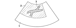
しかしながら、特許文献1や2のように、超音波画像に表示される領域の全体、或いは図9のように超音波画像1について設定された関心領域2の全体に対して、ドプラ計測を実施する方法では、血管3以外の領域からの信号に対しても周波数解析等の信号処理を行うことになるため、主に血管3の情報を得たい場合に信号処理全体として非効率である。
However, as in
本発明は上記問題に鑑みてなされたものであり、血管の情報を得たい場合により効率的にドプラ計測を実施することを可能とするドプラ計測装置およびドプラ計測方法を提供することを目的とするものである。 The present invention has been made in view of the above problems, and an object of the present invention is to provide a Doppler measurement apparatus and a Doppler measurement method that can perform Doppler measurement more efficiently when blood vessel information is desired. Is.
上記課題を解決するために、本発明に係るドプラ計測装置は、
音響送受信手段から被検体に向けて出射した音響波に基づく反射音響波の信号からドプラ偏移を受けた周波数信号を検出してドプラ計測を実施するドプラ計測装置において、
光音響効果に基づいて被検体内で生じ音響送受信手段によって検出された光音響波の信号に基づいて、被検体における血管領域を抽出し、抽出された血管領域を含みかつ音響送受信手段により規定される撮像可能範囲の一部である領域をドプラ計測対象領域として設定する抽出手段と、
抽出手段によって設定されたドプラ計測対象領域のみに対してドプラ計測が実施されるように音響送受信手段を制御する制御手段とを備えることを特徴とするものである。
In order to solve the above problems, a Doppler measurement device according to the present invention is
In a Doppler measurement device that performs Doppler measurement by detecting a frequency signal subjected to Doppler shift from a reflected acoustic wave signal based on an acoustic wave emitted from an acoustic transmission / reception means toward a subject,
Based on the photoacoustic wave signal generated in the subject based on the photoacoustic effect and detected by the acoustic transmission / reception means, the blood vessel region in the subject is extracted and includes the extracted blood vessel region and is defined by the acoustic transmission / reception means. Extracting means for setting a region that is a part of the imageable range as a Doppler measurement target region;
And a control unit that controls the acoustic transmission / reception unit so that the Doppler measurement is performed only on the Doppler measurement target region set by the extraction unit.
そして、本発明に係るドプラ計測装置において、抽出手段は、新たに光音響波の信号が検出された場合に、その信号に基づいて血管領域を再度抽出してドプラ計測対象領域を更新するものであり、制御手段は、更新されたドプラ計測対象領域のみに対してドプラ計測が実施されるように音響送受信手段を制御するものであることが好ましい。 In the Doppler measurement apparatus according to the present invention, when a photoacoustic wave signal is newly detected, the extraction unit extracts the blood vessel region again based on the signal and updates the Doppler measurement target region. In addition, it is preferable that the control unit controls the acoustic transmission / reception unit so that the Doppler measurement is performed only on the updated Doppler measurement target region.
また、本発明に係るドプラ計測装置において、抽出手段は、予め設定された値以上の光音響波の信号がまとまって観測された範囲の代表点または代表線から血管の半径として予め設定された距離の範囲内の領域を、ドプラ計測対象領域として設定するものであることが好ましい。 In the Doppler measurement device according to the present invention, the extraction means may have a distance set in advance as a radius of the blood vessel from a representative point or a representative line in a range in which a photoacoustic wave signal equal to or higher than a preset value is observed. It is preferable that the area within the range is set as the Doppler measurement target area.
また、本発明に係るドプラ計測装置は、ドプラ偏移を受けた周波数信号に基づいてドプラ画像を生成するドプラ画像生成手段を備えることが好ましい。 The Doppler measurement device according to the present invention preferably includes Doppler image generation means for generating a Doppler image based on the frequency signal subjected to Doppler shift.
また、本発明に係るドプラ計測装置において、さらに、光音響信号に基づいて光音響画像を生成する光音響画像生成手段を備えることが好ましい。 The Doppler measurement apparatus according to the present invention preferably further includes photoacoustic image generation means for generating a photoacoustic image based on the photoacoustic signal.
また、本発明に係るドプラ計測装置において、さらに、ドプラ画像と光音響画像とを重畳させて合成する画像合成手段を備えることが好ましい。 In the Doppler measurement apparatus according to the present invention, it is preferable that the Doppler measurement apparatus further includes an image synthesis unit that superimposes the Doppler image and the photoacoustic image.
また、本発明に係るドプラ計測装置において、ドプラ画像生成手段は、カラードプラモードまたはパワードプラモードのドプラ画像を生成するものであることが好ましい。 In the Doppler measurement device according to the present invention, it is preferable that the Doppler image generation unit generates a color Doppler mode or a power Doppler mode Doppler image.
また、本発明に係るドプラ計測装置は、さらに、被検体内で反射した反射音響波に基づいて反射音響画像を生成する反射音響画像生成手段を備えることが好ましい。 In addition, the Doppler measurement apparatus according to the present invention preferably further includes a reflected acoustic image generation unit that generates a reflected acoustic image based on the reflected acoustic wave reflected in the subject.
本発明に係るドプラ計測方法は、
音響送受信手段から被検体に向けて出射した音響波に基づく反射音響波の信号からドプラ偏移を受けた周波数信号を検出してドプラ計測を実施するドプラ計測方法において、
光音響効果に基づいて被検体内で生じた光音響波の信号を検出し、
検出された光音響波の信号に基づいて被検体における血管領域を抽出し、
抽出された血管領域を含みかつ音響送受信手段により規定される撮像可能範囲の一部である領域をドプラ計測対象領域として設定し、
設定されたドプラ計測対象領域のみに対してドプラ計測を実施することを特徴とするものである。
The Doppler measurement method according to the present invention includes:
In a Doppler measurement method for performing Doppler measurement by detecting a frequency signal subjected to Doppler shift from a reflected acoustic wave signal based on an acoustic wave emitted from an acoustic transmission / reception means toward a subject,
Detect photoacoustic wave signals generated in the subject based on the photoacoustic effect,
Extract blood vessel region in the subject based on the detected photoacoustic wave signal,
A region that includes the extracted blood vessel region and is a part of the imageable range defined by the acoustic transmission / reception means is set as a Doppler measurement target region,
The Doppler measurement is performed only on the set Doppler measurement target region.
そして、本発明に係るドプラ計測方法において、新たに光音響波の信号が検出された場合に、その信号に基づいて血管領域を再度抽出してドプラ計測対象領域を更新し、更新されたドプラ計測対象領域のみに対してドプラ計測を実施することが好ましい。 In the Doppler measurement method according to the present invention, when a photoacoustic wave signal is newly detected, the blood vessel region is extracted again based on the signal to update the Doppler measurement target region, and the updated Doppler measurement is performed. It is preferable to perform Doppler measurement only on the target region.
また、本発明に係るドプラ計測方法において、予め設定された値以上の光音響波の信号がまとまって観測された範囲の代表点または代表線から血管の半径として予め設定された距離の範囲内の領域を、ドプラ計測対象領域として設定することが好ましい。 Further, in the Doppler measurement method according to the present invention, a photoacoustic wave signal equal to or greater than a preset value within a range of distances set in advance as a radius of a blood vessel from a representative point or a representative line of the observed range. It is preferable to set the area as a Doppler measurement target area.
また、本発明に係るドプラ計測方法において、さらに、ドプラ偏移を受けた周波数信号に基づいてドプラ画像を生成することが好ましい。 In the Doppler measurement method according to the present invention, it is further preferable to generate a Doppler image based on the frequency signal subjected to the Doppler shift.
また、本発明に係るドプラ計測方法において、さらに、光音響信号に基づいて光音響画像を生成することが好ましい。 In the Doppler measurement method according to the present invention, it is further preferable to generate a photoacoustic image based on the photoacoustic signal.
また、本発明に係るドプラ計測方法において、さらに、ドプラ画像と光音響画像とを重畳させて合成することが好ましい。 Moreover, in the Doppler measurement method according to the present invention, it is preferable that the Doppler image and the photoacoustic image are superimposed and combined.
また、本発明に係るドプラ計測方法において、カラードプラモードまたはパワードプラモードのドプラ画像を生成することが好ましい。 In the Doppler measurement method according to the present invention, it is preferable to generate a color Doppler mode or power Doppler mode Doppler image.
また、本発明に係るドプラ計測方法において、さらに、被検体内で反射した反射音響波に基づいて反射音響画像を生成することが好ましい。 In the Doppler measurement method according to the present invention, it is further preferable to generate a reflected acoustic image based on the reflected acoustic wave reflected in the subject.
本発明に係るドプラ計測装置およびドプラ計測方法では、被検体内で生じた光音響波の信号に基づいて被検体における血管領域を抽出し、抽出された血管領域を含みかつ音響送受信手段により規定される撮像可能範囲の一部である領域をドプラ計測対象領域として設定し、設定されたドプラ計測対象領域のみに対してドプラ計測を実施するから、血管以外の領域からの信号に対するドプラ計測のための信号処理を減少させることができる。この結果、血管の情報を得たい場合により効率的にドプラ計測を実施することが可能となる。 In the Doppler measurement apparatus and the Doppler measurement method according to the present invention, the blood vessel region in the subject is extracted based on the photoacoustic wave signal generated in the subject, and includes the extracted blood vessel region and is defined by the acoustic transmission / reception means. An area that is a part of the imageable range is set as a Doppler measurement target area, and Doppler measurement is performed only on the set Doppler measurement target area. Therefore, for Doppler measurement on signals from areas other than blood vessels Signal processing can be reduced. As a result, the Doppler measurement can be performed more efficiently when blood vessel information is desired.
以下、本発明の実施形態について図面を用いて説明するが、本発明はこれに限られるものではない。なお、視認しやすくするため、図面中の各構成要素の縮尺等は実際のものとは適宜異ならせてある。 Hereinafter, although an embodiment of the present invention is described using a drawing, the present invention is not limited to this. In addition, for easy visual recognition, the scale of each component in the drawings is appropriately changed from the actual one.
「第1の実施形態」
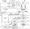
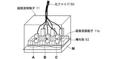
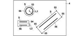
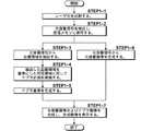
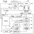
まず、本発明のドプラ計測装置およびドプラ計測方法の第1の実施形態について説明する。図1は、第1の実施形態におけるドプラ計測装置の構成を示す概略図である。また、図2は第1の実施形態における音響送受信手段の構成を示す概略図であり、図3は光音響画像上で血管領域を抽出する方法の例を示す概略図であり、図4は第1の実施形態における信号処理の流れを示すフロー図である。
“First Embodiment”
First, a first embodiment of the Doppler measurement device and the Doppler measurement method of the present invention will be described. FIG. 1 is a schematic diagram illustrating a configuration of a Doppler measurement apparatus according to the first embodiment. FIG. 2 is a schematic diagram showing the configuration of the acoustic transmission / reception means in the first embodiment, FIG. 3 is a schematic diagram showing an example of a method for extracting a blood vessel region on a photoacoustic image, and FIG. It is a flowchart which shows the flow of the signal processing in one Embodiment.
本実施形態のドプラ計測装置10は、特にドプラ画像生成機能および光音響画像生成機能を有する。具体的には図1に示されるように、ドプラ計測装置10は、超音波探触子(プローブ)11、超音波ユニット12、レーザユニット13および表示手段14を備えている。
The Doppler
<超音波探触子(プローブ)>
プローブ11は、被検体に向けて超音波を照射し、被検体M内を伝搬する音響波を検出するものである。このプローブ11が本発明における音響送受信手段に相当する。すなわち、プローブ11は、被検体Mに対する超音波の照射(送信)、および被検体Mから反射して戻って来る反射超音波の検出(受信)を行う。さらにプローブ11は、被検体M内の撮像対象物(例えば血管)がレーザ光を吸収することにより被検体M内に発生した光音響波の検出も行う。なお本明細書において、「音響波」とは超音波および光音響波を含む意味である。ここで、「超音波」とは、音響送受信手段による送信操作により被検体M内に発生した弾性波を意味し、「光音響波」とは測定光の照射による光音響効果により被検体M内に発生した弾性波を意味する。
<Ultrasonic probe (probe)>
The
プローブ11は、例えば一次元または二次元に配列された複数の超音波振動子11aから構成される振動子アレイを有する。超音波振動子11aは、例えば、圧電セラミクス、またはポリフッ化ビニリデン(PVDF)のような高分子フィルムから構成される圧電素子である。超音波振動子11aは、音響波を受信した場合にその受信信号を電気信号に変換する機能を有している。この電気信号は後述する受信回路21に出力される。このプローブ11は、セクタ走査対応、リニア走査対応、コンベックス走査対応等の中から診断部位に応じて選択される。
The
本実施形態のプローブ11は、図2に示されるように、超音波振動子11a、光ファイバ50および導光板52を備える。光ファイバ50は、レーザユニット13からのレーザ光を導光板52にまで導く。導光板52は、超音波振動子11aからなる振動子アレイの周囲に配置され、レーザ光はこの導光板52から照射される。プローブ11を上記のように構成することにより、同じ撮像範囲についてのドプラ画像(或いは後述する反射音響画像としての超音波画像)および光音響画像を精度よく生成することができる。これにより、ドプラ画像と光音響画像の複雑な位置合わせ処理が不要となる場合もある。
As shown in FIG. 2, the
レーザ光の照射は部分領域ごとに行ってもよい。例えば導光板52は、領域A、領域B、及び領域Cのそれぞれに対応して設けられる。その場合、領域Aに対応する導光板52aは領域Aの選択時にレーザ光を領域Aに照射する。また、領域Bに対応する導光板52bは領域Bの選択時にレーザ光を領域Bに照射する。そして、領域Cに対応する導光板52cは領域Cの選択時にレーザ光を領域Cに照射する。 Laser beam irradiation may be performed for each partial region. For example, the light guide plate 52 is provided corresponding to each of the region A, the region B, and the region C. In that case, the light guide plate 52a corresponding to the region A irradiates the region A with laser light when the region A is selected. The light guide plate 52b corresponding to the region B irradiates the region B with laser light when the region B is selected. The light guide plate 52c corresponding to the region C irradiates the region C with laser light when the region C is selected.
<レーザユニット>
レーザユニット13は、被検体Mに照射すべきレーザ光を測定光として出射する光出射部である。このレーザ光を被検体Mが吸収することにより被検体M内で光音響波が発生する。レーザユニット13が出射するレーザ光は、例えば光ファイバ50などの導光手段を用いてプローブ11の先端まで導光され、プローブ11から被検体Mに照射される。なお、レーザ光を出射させる位置はプローブ11内に限定されない。
<Laser unit>
The
例えば本実施形態においてレーザユニット13は、励起光源であるフラッシュランプ35とレーザ発振を制御するQスイッチとを含むQスイッチアレキサンドライトレーザである。レーザユニット13は、制御手段34内のトリガ制御回路が光トリガ信号を出力すると、フラッシュランプ35を点灯し、Qスイッチレーザ36を励起する。例えば本実施形態ではレーザユニット13は、レーザ光として1〜100nsecのパルス幅を有するパルス光を出力するものであることが好ましい。レーザ光の波長は、計測の対象となる被検体内の物質の光吸収特性によって適宜決定される。生体内のヘモグロビンは、その状態(酸素化ヘモグロビン、脱酸素化ヘモグロビン、メトヘモグロビン等)により光学的な吸収特性が異なるが、一般的には360〜1000nmの光を吸収する。したがって、生体内でのヘモグロビンを計測する場合には、他の生体物質の吸収が比較的少ない600〜1000nmの程度とすることが好ましい。また、より生体内での被検体の深部まで届くという観点から、レーザ光の波長は700〜1000nmであることが好ましい。
For example, in this embodiment, the
なお、レーザユニット13としては、特定の波長成分又はその成分を含む単色光を発生する半導体レーザ(LD)、固体レーザ、ガスレーザ等の発光素子を用いることもできる。
The
<超音波ユニット>
超音波ユニット12は、受信回路21、AD変換手段22、受信メモリ23、光音響画像生成手段25、ドプラ画像生成手段29、画像合成手段30、血管領域を抽出する抽出手段28、送信制御回路33および制御手段34を有している。
<Ultrasonic unit>
The
受信回路21は、プローブ11中の超音波振動子11aから出力された音響波の電気信号を受信する。AD変換手段22はサンプリング手段であり、受信回路21が受信した電気信号を例えばクロック周波数40MHzのADクロック信号に同期してサンプリングしてデジタル信号に変換する。AD変換手段22は、例えば外部から入力されるADクロック信号に同期して、所定のサンプリング周期で上記電気信号をサンプリングする。
The receiving
AD変換手段22は、サンプリングしたデジタル信号(サンプリングデータ)を受信メモリ23に格納する。受信メモリ23に格納されたサンプリングデータは、光音響波に関するデータ(光音響データ)または超音波に関するデータ(超音波データ)である。
The AD conversion means 22 stores the sampled digital signal (sampling data) in the
光音響画像生成手段25は、例えば受信メモリに格納された上記光音響データを、超音波振動子の位置に応じた遅延時間で互いに加算して1ライン分のデータを再構成し、各ラインの光音響データに基づいて断層画像(光音響画像)のデータを生成する。なお、この光音響画像生成手段25は、遅延加算法に代えて、CBP法(Circular Back Projection)により再構成を行うものでもよい。あるいは光音響画像生成手段25は、ハフ変換法又はフーリエ変換法を用いて再構成を行うものでもよい。光音響画像生成手段25は、上記のようにして生成された光音響画像のデータを画像合成手段30に出力する。
For example, the photoacoustic image generation means 25 adds the photoacoustic data stored in the reception memory to each other with a delay time corresponding to the position of the ultrasonic transducer to reconstruct data for one line, and Data of a tomographic image (photoacoustic image) is generated based on the photoacoustic data. In addition, this photoacoustic image generation means 25 may replace with a delay addition method, and may perform a reconstruction by CBP method (Circular Back Projection). Alternatively, the photoacoustic
一方、抽出手段28は、受信メモリ23に記憶されたサンプリングデータから同様に、光音響データを再構成し、光音響画像のデータを生成し、この光音響画像データに基づいて被検体M内における血管領域(血管58の存在する領域)を抽出する。そして、抽出手段28は、抽出された血管領域の情報に基づいて、抽出された血管領域を含みかつプローブ11(音響送受信手段)により規定される撮像可能範囲(いわゆるスキャン面)の一部である領域をドプラ計測対象領域として設定する。つまり、抽出手段28は、被検体M内における血管の場所を特定するための情報を取得し、さらにドプラ計測を実施する領域を特定する機能を果たす。プローブにより規定される撮像可能範囲は、個々のプローブによって様々であるが、一般的に振動子アレイがリニア型である場合には矩形状の範囲であり、コンベックス型またはセクタ型である場合には扇形状の範囲である。血管領域の抽出方法は、特に制限されず既知の画像処理方法により行うことができ、例えば光音響画像中の画素値の大きさに基づいて判断される。一般に血管は他の組織に比べて光の吸収係数が大きいため、人体からの光音響信号は血管からの信号であるとみなすことが可能である。したがって、抽出手段28は、例えば光音響画像において画素値が所定の値を超える場所を血管に対応する画像領域として抽出する。スムージング処理によりノイズを除去する処理など他の信号処理と組み合わせることも可能である。ドプラ計測対象領域は、抽出された血管領域を含むように設定される。ドプラ計測対象領域を特定するための情報としては、例えば、画素値が所定の値を超える全ての画素位置そのものの情報、予め設定された値以上の画素(光音響信号)がまとまって観測された範囲(サンプルボリューム領域)を示す情報などが挙げられる。例えば、サンプルボリューム領域Sを示す情報としては、図3に示されるような撮像可能範囲4において、予め設定された値以上の画素の集合56を含む領域Sの任意の代表点53の位置およびこの代表点53からの距離L1の情報、領域Sの任意の代表線54の位置およびこの代表線54からの距離L2の情報、および領域Sの各頂点55の位置情報等が挙げられる。領域Sの大きさや形状は、血管の太さ、長さ、方向および分岐等の構造的な特徴、並びに、血管の長さ方向(血液の流れる方向)に対する撮像断面の角度等の撮像条件を考慮して、画素値が所定の値を超える画素の集合56(つまり血管と推定される領域)が適切に含まれるように適宜設定される。図3では、例えば平行に並んでいる画素の集合56同士を1つの血管であるとみなして一組にしてサンプルボリューム領域Sを設定している。光音響計測においては、1つの血管であっても、血管壁の表面側と深部側とで光音響信号のピークが分かれて観測されることがあるためである。
On the other hand, the extraction means 28 similarly reconstructs photoacoustic data from the sampling data stored in the
なお、抽出手段28が独自に光音響画像データを生成せずに、光音響画像生成手段25によって生成された光音響画像データを抽出手段28が取得してこの光音響画像データに基づいて被検体内における血管領域を抽出する態様でもよい。この場合には、重複して光音響画像データを生成する手間を省くことができる。また、上記では光音響画像データに基づいて血管領域を抽出する場合について説明したが、例えば血管領域は、画像化される前の光音響データに基づいて抽出することもできる。この場合には、例えば光音響信号のピーク位置を血管が存在する位置と推定することができる。抽出手段28によって設定されたドプラ計測対象領域の情報は、制御手段34へと出力される。
The extraction means 28 does not generate the photoacoustic image data independently, but the extraction means 28 acquires the photoacoustic image data generated by the photoacoustic image generation means 25, and the subject is based on the photoacoustic image data. It is also possible to extract the blood vessel region inside. In this case, the trouble of generating photoacoustic image data redundantly can be saved. In the above description, the blood vessel region is extracted based on the photoacoustic image data. However, for example, the blood vessel region can be extracted based on the photoacoustic data before being imaged. In this case, for example, the peak position of the photoacoustic signal can be estimated as the position where the blood vessel exists. Information on the Doppler measurement target area set by the
制御手段34は、超音波ユニット12内の各部を制御する。例えば制御手段34は、レーザユニット13に対してレーザ光の出力を指示するフラッシュランプトリガ信号を出力する。これによりレーザユニット13では、フラッシュランプトリガ信号に応答してフラッシュランプ35が点灯し、レーザ励起が開始される。その後、制御手段34は、所定のタイミングでQスイッチトリガ信号を出力する。これによりレーザユニット13では、Qスイッチレーザ36のQスイッチがQスイッチトリガ信号に応答してON状態となり、レーザ光が出力されて、被検体Mにレーザ光が照射される。また制御手段34は、抽出手段28によって出力されたドプラ計測対象領域の情報を受け取り、後述するようにドプラ計測用に送信超音波を送信する方向を決定する。そして、決定した方向に超音波が送信されるように、制御手段34は、個々の超音波振動子11aを同時にまたは時間差を付けて駆動させる旨の超音波トリガ信号を送信制御回路33に出力する。送信制御回路33は、その超音波トリガ信号に従って超音波振動子11aを駆動させる。つまり本実施形態では、制御手段34は、送信制御回路33を介してプローブ11を制御している。
The control means 34 controls each part in the
ドプラ画像生成手段29は、例えば制御手段34から取得した送信超音波の周波数と受信した反射超音波の周波数との差(ドプラ偏移)に基づいてドプラ画像を生成する。この際、ドプラ画像生成手段29は、例えば制御手段34から(或いは直接抽出手段28から)ドプラ計測対象領域の情報を取得し、この情報に基づいて、超音波が送信された方向(いわゆる深さ方向)においても走査ライン上の領域のうちドプラ計測対象領域として設定されている領域についてのみ画像化を行う。超音波が送信された走査ライン上の領域であっても、血管が存在しなければ画像化の必要性が乏しいためである。生成されたドプラ画像のデータは画像合成手段30に出力される。ドプラ画像の生成方法としては従来の方法を採用することができる。ドプラ画像生成手段29は、ドプラ画像としてカラードプラモードまたはパワードプラモードの画像を生成することが好ましい。カラードプラモードの場合には血液の流れを色分けすることが可能となり、パワードプラモードの場合には細い血管を観察しやすくなるという効果が得られる。
For example, the Doppler
画像合成手段30は、光音響画像生成手段25から取得した光音響画像データ上にドプラ画像生成手段29から取得したドプラ画像データを重畳させてこれらの画像を合成し、その合成画像が表示手段14に表示されるように表示手段14を制御する。これにより、ドプラ計測により得られる血管情報を光音響画像上で確認しながら画像中の血管を観察することが可能となる。例えば、カラードプラモードのドプラ画像を光音響画像上に重畳させた場合には、光音響画像中に表示された血管の血流の向きや速さを血管の観察と共に確認することができる。また、パワードプラモードのドプラ画像を光音響画像上に重畳させた場合には、光音響計測では信号が弱く光音響画像中に表示されにくい或いは表示されない血管を確認することができる。表示されにくい或いは表示されない血管としては、例えば光音響信号自体が生じにくい細い血管や被検体表面に対して垂直な方向に伸びる血管等が挙げられる。
The
画像合成手段30は、プローブ11が二次元配列した振動子アレイを有することにより複数の断層画像(光音響画像およびドプラ画像を含む)が取得された場合には、それらの断層画像に基づいてボリュームデータを作成し、三次元画像として合成画像を表示手段14に表示させてもよい。
When a plurality of tomographic images (including a photoacoustic image and a Doppler image) are acquired by the
以下、図4を用いてドプラ計測方法の流れについて説明する。まず、ドプラ計測装置10の電源が入力されると制御手段34はフラッシュランプトリガ信号をフラッシュランプ35に送信し、これによりフラッシュランプが点灯し、Qスイッチレーザ36が励起される。断層画像を取得したい部分の被検体表面にプローブ11が当てられた状態で、図示しない測定開始用のボタンが押下されると、制御手段34はQスイッチトリガ信号をQスイッチレーザ36に送信し、これによりQスイッチレーザ36からレーザ光が被検体Mに向けて出射する(STEP1−1)。そして、レーザ光を受けた被検体M内で光音響波が発生し、プローブ11で光音響信号が検出され、メモリに保存される(STEP1−2)。
Hereinafter, the flow of the Doppler measurement method will be described with reference to FIG. First, when the power supply of the
すると、抽出手段28が、光音響信号から光音響画像を構築し、光音響画像中の血管領域を抽出し(STEP1−3)、抽出された血管領域に基づき血管が存在すると推定されるサンプルボリューム領域をドプラ計測対象領域として設定する。そして、制御手段34が、そのドプラ計測対象領域のみに対してドプラ計測が実施されるように、送信制御回路33へ超音波トリガ信号を送信する。この結果、送信制御回路33は、その超音波トリガ信号に基づきこのドプラ計測対象領域が存在する走査ラインのみに対してパルス超音波が送信されるように振動子アレイを動作させ(STEP1−4)、ドプラ画像生成手段29はそのドプラ計測対象領域のみにおいてドプラ画像を生成する(STEP1−5)。
Then, the extraction means 28 constructs a photoacoustic image from the photoacoustic signal, extracts a blood vessel region in the photoacoustic image (STEP 1-3), and a sample volume in which a blood vessel is estimated to exist based on the extracted blood vessel region. The region is set as the Doppler measurement target region. Then, the
一方、光音響画像生成手段25は、STEP1−2でメモリに保存された光音響信号に基づいて光音響画像を生成する(STEP1−6)。STEP1−6で生成された光音響画像は、画像合成手段30に出力され、STEP1−5で生成されたドプラ画像と重畳されて合成され、合成画像が表示手段14に表示される(STEP1−7)。ここまでの工程で、1フレーム分の合成された断層画像が生成される。つまり、例えば画像を動画としてリアルタイムに被検体内を観察する場合には、プローブ11を被検体表面に対して固定して、すなわち振動子アレイによって規定される撮像可能範囲を固定して、STEP1−1からSTEP1−7の工程を複数回繰り返す。このように、直前に取得された光音響信号に基づいてドプラ計測対象領域を随時更新し、さらに光音響信号を検出する周期とドプラ計測を行う周期を同期することで、より正確な血管領域情報に基づいてドプラ計測を実施することができるため、ドプラ計測の精度が向上する。
On the other hand, the photoacoustic image generation means 25 generates a photoacoustic image based on the photoacoustic signal stored in the memory in STEP1-2 (STEP1-6). The photoacoustic image generated in STEP 1-6 is output to the
なお、光音響信号を検出する周期とドプラ計測を行う周期は必ずしも同期している必要はない。これらが同期していない場合には、ドプラ計測は、例えば直前に設定された(つまり最後に更新された)ドプラ計測対象領域のみに対して実施される。 The period for detecting the photoacoustic signal and the period for performing Doppler measurement are not necessarily synchronized. If they are not synchronized, the Doppler measurement is performed, for example, only on the Doppler measurement target area set immediately before (that is, updated last).
以上のように、本実施形態に係るドプラ計測装置およびドプラ計測方法では、被検体内で生じた光音響波の信号に基づいて被検体における血管領域を抽出し、抽出された血管領域を含みかつ音響送受信手段により規定される撮像可能範囲の一部であるドプラ計測対象領域を設定し、設定されたドプラ計測対象領域のみに対してドプラ計測を実施するから、血管以外の領域からの信号に対するドプラ計測のための信号処理を減少させることができる。 As described above, in the Doppler measurement device and the Doppler measurement method according to the present embodiment, the blood vessel region in the subject is extracted based on the photoacoustic wave signal generated in the subject, and includes the extracted blood vessel region and Since the Doppler measurement target area, which is a part of the imageable range defined by the acoustic transmission / reception means, is set, and Doppler measurement is performed only on the set Doppler measurement target area, Doppler for signals from areas other than blood vessels is performed. Signal processing for measurement can be reduced.
つまり、機能的な断層画像をリアルタイムに表示するため、ドプラ計測および光音響計測を交互スキャン方式で実施する場合には、例えば単純計算でフレームレートが2分の1になってしまい、リアルタイム性が低下してしまう。一方、フレームレートを低下させないために、光音響画像の撮像範囲に比べドプラ計測対象領域を小さく絞ってしまうと血管情報の全体観察ができなくなってしまう。そこで、本実施形態のドプラ計測装置およびドプラ計測方法は、ドプラ計測の対象を血管が存在すると推定される所定領域に限定し、血管観察に必要性の低い領域をドプラ計測の対象から除外することで、血管情報の全体観察を確保しながらフレームレートの低下を抑制している。この結果、血管の情報を得たい場合により効率的にドプラ計測を実施することが可能となる。 In other words, in order to display a functional tomographic image in real time, when Doppler measurement and photoacoustic measurement are performed by an alternate scan method, for example, the frame rate is halved by simple calculation, and real-time characteristics are reduced. It will decline. On the other hand, in order not to reduce the frame rate, if the Doppler measurement target region is narrowed down compared to the imaging range of the photoacoustic image, the entire blood vessel information cannot be observed. Therefore, in the Doppler measurement apparatus and the Doppler measurement method of the present embodiment, the Doppler measurement target is limited to a predetermined region where a blood vessel is estimated to exist, and a region that is less necessary for blood vessel observation is excluded from the Doppler measurement target. Therefore, a decrease in the frame rate is suppressed while ensuring the entire observation of the blood vessel information. As a result, the Doppler measurement can be performed more efficiently when blood vessel information is desired.
「第2の実施形態」
次に、本発明のドプラ計測装置およびドプラ計測方法の第2の実施形態について説明する。本実施形態は、光音響画像に代えて超音波画像にドプラ画像を重畳させる点で、第1の実施形態と異なる。したがって、第1の実施形態と同様の構成要素については同じ符号を付し、その詳細な説明は特に必要のない限り省略する。
“Second Embodiment”
Next, a second embodiment of the Doppler measurement device and the Doppler measurement method of the present invention will be described. This embodiment is different from the first embodiment in that a Doppler image is superimposed on an ultrasonic image instead of a photoacoustic image. Therefore, the same components as those in the first embodiment are denoted by the same reference numerals, and detailed description thereof is omitted unless particularly necessary.
図5は、第2の実施形態におけるドプラ計測装置の構成を示す概略図である。また、図6は第2の実施形態における信号処理の流れを示すフロー図である。 FIG. 5 is a schematic diagram illustrating a configuration of a Doppler measurement device according to the second embodiment. FIG. 6 is a flowchart showing the flow of signal processing in the second embodiment.
本実施形態のドプラ計測装置10は、特にドプラ画像生成機能および超音波画像生成機能を有する。具体的には図5に示されるように、ドプラ計測装置10は、超音波探触子(プローブ)11、超音波ユニット12、レーザユニット13および表示手段14を備えている。プローブ11、レーザユニット13および表示手段14は第1の実施形態と同様のものである。
The
<超音波ユニット>
超音波ユニット12は、受信回路21、AD変換手段22、受信メモリ23、超音波画像生成手段26、ドプラ画像生成手段29、画像合成手段30、血管領域を抽出する抽出手段28、送信制御回路33および制御手段34を有している。
<Ultrasonic unit>
The
超音波画像生成手段26は、プローブ11の複数の超音波振動子11aで検出された反射超音波(より具体的にはそのサンプリングデータ)に基づいて、個々の超音波振動子11aの位置に応じた遅延時間で加算して1ライン分のデータを再構成し、各ラインの超音波データに基づいて、断層画像(超音波画像)のデータを生成する。各ラインのデータの生成には、光音響画像生成手段25における各ラインのデータの生成と同様に、遅延加算法などを用いることができる。超音波画像生成手段26は、必要に応じて検波処理や対数変換処理を行ってもよい。
The ultrasonic image generating means 26 corresponds to the position of each ultrasonic transducer 11a based on the reflected ultrasonic waves (more specifically, the sampling data) detected by the multiple ultrasonic transducers 11a of the
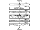
以下、図6を用いてドプラ計測方法の流れについて説明する。まず、STEP2−1およびSTEP2−2は、第1の実施形態におけるSTEP1−1およびSTEP1−2と同様である。つまり、本実施形態では光音響画像は表示手段に表示されないが、血管領域を抽出するために抽出手段28が光音響画像を生成している。
Hereinafter, the flow of the Doppler measurement method will be described with reference to FIG. First, STEP2-1 and STEP2-2 are the same as STEP1-1 and STEP1-2 in the first embodiment. That is, in this embodiment, the photoacoustic image is not displayed on the display unit, but the
抽出手段28は、光音響信号から光音響画像を構築し、光音響画像中の血管領域を抽出し(STEP2−3)、抽出された血管領域に基づき血管が存在すると推定されるサンプルボリューム領域をドプラ計測対象領域として設定する。なお、前述したように、抽出手段28は、画像化される前の光音響データに基づいて抽出してもよい。そして、制御手段34が、そのドプラ計測対象領域のみに対してドプラ計測が実施され、かつ撮像可能範囲全体に対して超音波計測が実施されるように、送信制御回路33へ超音波トリガ信号を送信する。送信制御回路33は、走査ラインを徐々にずらしながら、ドプラ計測用の超音波と超音波計測用の超音波とを交互に送信し、プローブ11はこれらの反射超音波を交互に受信する(STEP2−4)。なお、送信制御回路33は、ドプラ計測においては、ドプラ計測対象領域が存在する走査ラインのみに対してパルス超音波が送信されるように振動子アレイを動作させる。ドプラ画像生成手段29はそのドプラ計測対象領域のみにおいてドプラ画像を生成し、超音波画像生成手段26は撮像可能範囲全体の超音波画像を生成する(STEP2−5)。
The
STEP2−5で生成されたドプラ画像および超音波画像は、それぞれ画像合成手段30に出力され、そこで重畳されて合成され、その後合成画像が表示手段14に表示される(STEP2−6)。ここまでの工程で、1フレーム分の合成された断層画像が生成される。つまり、例えば画像を動画としてリアルタイムに被検体内を観察する場合には、プローブ11を被検体表面に対して固定して、すなわち振動子アレイによって規定される撮像可能範囲を固定して、STEP2−1からSTEP2−6の工程を複数回繰り返す。
The Doppler image and the ultrasonic image generated in STEP 2-5 are each output to the
以上のように、本実施形態に係るドプラ計測装置およびドプラ計測方法でも、被検体内で生じた光音響波の信号に基づいて被検体における血管領域を抽出し、抽出された血管領域を含みかつ音響送受信手段により規定される撮像可能範囲の一部であるドプラ計測対象領域を設定し、設定されたドプラ計測対象領域のみに対してドプラ計測を実施するから、第1の実施形態と同様の効果が得られる。 As described above, also in the Doppler measurement apparatus and the Doppler measurement method according to the present embodiment, the blood vessel region in the subject is extracted based on the photoacoustic wave signal generated in the subject, and includes the extracted blood vessel region and Since the Doppler measurement target area that is a part of the imageable range defined by the acoustic transmission / reception means is set and the Doppler measurement is performed only on the set Doppler measurement target area, the same effect as the first embodiment Is obtained.
さらに本実施形態では、超音波画像にドプラ画像を重畳しているから、超音波画像の広い範囲において血管情報を確認しながら超音波画像を観察することが可能となる。 Furthermore, in this embodiment, since the Doppler image is superimposed on the ultrasound image, it is possible to observe the ultrasound image while confirming blood vessel information in a wide range of the ultrasound image.
「第3の実施形態」
次に、本発明のドプラ計測装置およびドプラ計測方法の第3の実施形態について説明する。本実施形態は、光音響画像、超音波画像およびドプラ画像を重畳させる点で、第1の実施形態と異なる。したがって、第1の実施形態と同様の構成要素については同じ符号を付し、その詳細な説明は特に必要のない限り省略する。
“Third Embodiment”
Next, a third embodiment of the Doppler measurement device and the Doppler measurement method of the present invention will be described. This embodiment is different from the first embodiment in that a photoacoustic image, an ultrasonic image, and a Doppler image are superimposed. Therefore, the same components as those in the first embodiment are denoted by the same reference numerals, and detailed description thereof is omitted unless particularly necessary.
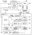
図7は、第3の実施形態におけるドプラ計測装置の構成を示す概略図である。また、図8は第3の実施形態における信号処理の流れを示すフロー図である。 FIG. 7 is a schematic diagram illustrating a configuration of a Doppler measurement device according to the third embodiment. FIG. 8 is a flowchart showing the flow of signal processing in the third embodiment.
本実施形態のドプラ計測装置10は、特にドプラ画像生成機能、光音響画像生成機能および超音波画像生成機能を有する。具体的には図7に示されるように、ドプラ計測装置10は、超音波探触子(プローブ)11、超音波ユニット12、レーザユニット13および表示手段14を備えている。プローブ11、レーザユニット13および表示手段14は第1の実施形態と同様のものである。
The
<超音波ユニット>
超音波ユニット12は、受信回路21、AD変換手段22、受信メモリ23、光音響画像生成手段25、超音波画像生成手段26、ドプラ画像生成手段29、画像合成手段30、血管領域を抽出する抽出手段28、送信制御回路33および制御手段34を有している。光音響画像生成手段25は第1の実施形態で説明したものと同様であり、超音波画像生成手段26は第2の実施形態で説明したものと同様である。
<Ultrasonic unit>
The
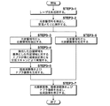
以下、図8を用いてドプラ計測方法の流れについて説明する。まず、STEP3−1およびSTEP3−2は、第1の実施形態におけるSTEP1−1およびSTEP1−2と同様である。 Hereinafter, the flow of the Doppler measurement method will be described with reference to FIG. First, STEP3-1 and STEP3-2 are the same as STEP1-1 and STEP1-2 in the first embodiment.
抽出手段28は、光音響信号から光音響画像を構築し、光音響画像中の血管領域を抽出し(STEP3−3)、抽出された血管領域に基づき血管が存在すると推定されるサンプルボリューム領域をドプラ計測対象領域として設定する。なお、前述したように、抽出手段28は、画像化される前の光音響データに基づいて抽出してもよい。そして、制御手段34が、そのドプラ計測対象領域のみに対してドプラ計測が実施され、かつ撮像可能範囲全体に対して超音波計測が実施されるように、送信制御回路33へ超音波トリガ信号を送信する。送信制御回路33は、走査ラインを徐々にずらしながら、ドプラ計測用の超音波と超音波計測用の超音波とを交互に送信し、プローブ11はこれらの反射超音波を交互に受信する(STEP3−4)。なお、送信制御回路33は、ドプラ計測においては、ドプラ計測対象領域が存在する走査ラインのみに対してパルス超音波が送信されるように振動子アレイを動作させる。ドプラ画像生成手段29はそのドプラ計測対象領域のみにおいてドプラ画像を生成し、超音波画像生成手段26は撮像可能範囲全体の超音波画像を生成する(STEP3−5)。
The
一方、光音響画像生成手段25は、STEP3−2でメモリに保存された光音響信号に基づいて光音響画像を生成する(STEP3−6)。 On the other hand, the photoacoustic image generation means 25 generates a photoacoustic image based on the photoacoustic signal stored in the memory in STEP 3-2 (STEP 3-6).
STEP3−5で生成されたドプラ画像および超音波画像、並びにSTEP3−6で生成された光音響画像は、それぞれ画像合成手段30に出力され、そこで重畳されて合成され、その後合成画像が表示手段14に表示される(STEP3−7)。ここまでの工程で、1フレーム分の合成された断層画像が生成される。つまり、例えば画像を動画としてリアルタイムに被検体内を観察する場合には、プローブ11を被検体表面に対して固定して、すなわち振動子アレイによって規定される撮像可能範囲を固定して、STEP3−1からSTEP3−7の工程を複数回繰り返す。
The Doppler image and the ultrasonic image generated in STEP 3-5 and the photoacoustic image generated in STEP 3-6 are each output to the
以上のように、本実施形態に係るドプラ計測装置およびドプラ計測方法でも、被検体内で生じた光音響波の信号に基づいて被検体における血管領域を抽出し、抽出された血管領域を含みかつ音響送受信手段により規定される撮像可能範囲の一部であるドプラ計測対象領域を設定し、設定されたドプラ計測対象領域のみに対してドプラ計測を実施するから、第1の実施形態と同様の効果が得られる。 As described above, also in the Doppler measurement apparatus and the Doppler measurement method according to the present embodiment, the blood vessel region in the subject is extracted based on the photoacoustic wave signal generated in the subject, and includes the extracted blood vessel region and Since the Doppler measurement target area that is a part of the imageable range defined by the acoustic transmission / reception means is set and the Doppler measurement is performed only on the set Doppler measurement target area, the same effect as the first embodiment Is obtained.
さらに本実施形態では、超音波画像にドプラ画像に加え光音響画像を重畳しているから、超音波画像の広い範囲においてより正確な血管領域を確認しながら超音波画像を観察することが可能となる。これは、光音響計測では、例えば光音響信号自体が生じにくい細い血管や被検体表面に対して垂直な方向に伸びる血管等が画像化されにくいという特徴があり、ドプラ計測では、流速の遅い血管や被検体表面に対して平行な方向に伸びる血管等が画像化されにくいという特徴があるが、ドプラ画像および光音響画像を重畳することで、ドプラ画像および光音響画像の一方が画像化しにくい血管を他方が相補的に画像化することができるためである。 Furthermore, in this embodiment, since the photoacoustic image is superimposed on the ultrasonic image in addition to the Doppler image, it is possible to observe the ultrasonic image while confirming a more accurate blood vessel region in a wide range of the ultrasonic image. Become. This is because, in photoacoustic measurement, for example, a thin blood vessel that is difficult to generate a photoacoustic signal itself or a blood vessel that extends in a direction perpendicular to the subject surface is difficult to be imaged. Or blood vessels that extend in a direction parallel to the subject surface are difficult to image, but by superimposing the Doppler image and the photoacoustic image, one of the Doppler image and the photoacoustic image is difficult to image. This is because the other can be complementarily imaged.
1 超音波画像
2 関心領域
3 血管
4 撮像可能範囲
10 ドプラ計測装置
11 プローブ
11a 超音波振動子
12 超音波ユニット
13 レーザユニット
14 表示手段
21 受信回路
22 変換手段
23 受信メモリ
25 光音響画像生成手段
26 超音波画像生成手段
28 抽出手段
29 ドプラ画像生成手段
30 画像合成手段
33 送信制御回路
34 制御手段
35 フラッシュランプ
36 スイッチレーザ
50 光ファイバ
52 導光板
56 予め設定された値以上の画素の集合
M 被検体
S サンプルボリューム領域
DESCRIPTION OF
Claims (16)
光音響効果に基づいて前記被検体内で生じ前記音響送受信手段によって検出された光音響波の信号に基づいて、前記被検体における血管領域を抽出し、抽出された血管領域を含みかつ前記音響送受信手段により規定される撮像可能範囲の一部である領域をドプラ計測対象領域として設定する抽出手段と、
該抽出手段によって設定されたドプラ計測対象領域のみに対してドプラ計測が実施されるように前記音響送受信手段を制御する制御手段とを備えることを特徴とするドプラ計測装置。 In a Doppler measurement device that performs Doppler measurement by detecting a frequency signal subjected to Doppler shift from a reflected acoustic wave signal based on an acoustic wave emitted from an acoustic transmission / reception means toward a subject,
Based on a photoacoustic wave signal generated in the subject based on a photoacoustic effect and detected by the acoustic transmission / reception means, a blood vessel region in the subject is extracted, and includes the extracted blood vessel region, and the acoustic transmission / reception includes Extraction means for setting an area that is a part of the imageable range defined by the means as a Doppler measurement target area;
A Doppler measurement apparatus comprising: a control unit that controls the acoustic transmission / reception unit so that Doppler measurement is performed only on a Doppler measurement target region set by the extraction unit.
前記制御手段が、更新されたドプラ計測対象領域のみに対してドプラ計測が実施されるように前記音響送受信手段を制御するものであることを特徴とする請求項1に記載のドプラ計測装置。 When the extraction means newly detects a photoacoustic wave signal, the blood vessel region is extracted again based on the signal, and the Doppler measurement target region is updated.
The Doppler measurement apparatus according to claim 1, wherein the control means controls the acoustic transmission / reception means so that Doppler measurement is performed only on the updated Doppler measurement target region.
光音響効果に基づいて前記被検体内で生じた光音響波の信号を検出し、
検出された前記光音響波の信号に基づいて前記被検体における血管領域を抽出し、
抽出された血管領域を含みかつ前記音響送受信手段により規定される撮像可能範囲の一部である領域をドプラ計測対象領域として設定し、
設定されたドプラ計測対象領域のみに対してドプラ計測を実施することを特徴とするドプラ計測方法。 In a Doppler measurement method for performing Doppler measurement by detecting a frequency signal subjected to Doppler shift from a reflected acoustic wave signal based on an acoustic wave emitted from an acoustic transmission / reception means toward a subject,
Detecting a photoacoustic wave signal generated in the subject based on a photoacoustic effect;
Extracting a blood vessel region in the subject based on the detected photoacoustic wave signal;
A region that includes the extracted blood vessel region and is a part of the imageable range defined by the acoustic transmission / reception means is set as a Doppler measurement target region,
A Doppler measurement method, wherein Doppler measurement is performed only on a set Doppler measurement target region.
更新されたドプラ計測対象領域のみに対してドプラ計測を実施することを特徴とする請求項9に記載のドプラ計測方法。 When a photoacoustic wave signal is newly detected, the blood vessel region is extracted again based on the signal to update the Doppler measurement target region,
The Doppler measurement method according to claim 9, wherein Doppler measurement is performed only on the updated Doppler measurement target region.
Priority Applications (1)
| Application Number | Priority Date | Filing Date | Title |
|---|---|---|---|
| JP2013007130A JP6177530B2 (en) | 2013-01-18 | 2013-01-18 | Doppler measuring device and doppler measuring method |
Applications Claiming Priority (1)
| Application Number | Priority Date | Filing Date | Title |
|---|---|---|---|
| JP2013007130A JP6177530B2 (en) | 2013-01-18 | 2013-01-18 | Doppler measuring device and doppler measuring method |
Publications (2)
| Publication Number | Publication Date |
|---|---|
| JP2014136102A true JP2014136102A (en) | 2014-07-28 |
| JP6177530B2 JP6177530B2 (en) | 2017-08-09 |
Family
ID=51413957
Family Applications (1)
| Application Number | Title | Priority Date | Filing Date |
|---|---|---|---|
| JP2013007130A Active JP6177530B2 (en) | 2013-01-18 | 2013-01-18 | Doppler measuring device and doppler measuring method |
Country Status (1)
| Country | Link |
|---|---|
| JP (1) | JP6177530B2 (en) |
Cited By (7)
| Publication number | Priority date | Publication date | Assignee | Title |
|---|---|---|---|---|
| WO2016111105A1 (en) * | 2015-01-08 | 2016-07-14 | 富士フイルム株式会社 | Photoacoustic measuring device and photoacoustic measuring system |
| WO2016111100A1 (en) * | 2015-01-08 | 2016-07-14 | 富士フイルム株式会社 | Photoacoustic measuring device and photoacoustic measuring system |
| WO2016157780A1 (en) * | 2015-03-30 | 2016-10-06 | 富士フイルム株式会社 | Photoacoustic measurement device and system |
| WO2017138459A1 (en) * | 2016-02-08 | 2017-08-17 | 富士フイルム株式会社 | Acoustic wave image generation device and acoustic wave image generation method |
| WO2018056186A1 (en) * | 2016-09-21 | 2018-03-29 | 富士フイルム株式会社 | Photoacoustic measurement apparatus |
| WO2018056187A1 (en) * | 2016-09-21 | 2018-03-29 | 富士フイルム株式会社 | Photoacoustic image-generating apparatus |
| CN113367660A (en) * | 2021-06-09 | 2021-09-10 | 东北大学秦皇岛分校 | Photoacoustic Doppler flow velocity measuring device and method |
Citations (7)
| Publication number | Priority date | Publication date | Assignee | Title |
|---|---|---|---|---|
| JPH10118068A (en) * | 1996-10-21 | 1998-05-12 | Toshiba Corp | Ultrasonograph |
| JP2008539932A (en) * | 2005-05-10 | 2008-11-20 | コーニンクレッカ フィリップス エレクトロニクス エヌ ヴィ | Cannula insertion system |
| US20090118670A1 (en) * | 2005-04-22 | 2009-05-07 | Sieglinde Neerken | Cannula inserting system |
| JP2010051798A (en) * | 2008-08-27 | 2010-03-11 | Medison Co Ltd | Method for performing adaptive color doppler mode and ultrasonic wave diagnosis system for the same |
| JP2010512929A (en) * | 2006-12-19 | 2010-04-30 | コーニンクレッカ フィリップス エレクトロニクス エヌ ヴィ | Combined photoacoustic and ultrasonic imaging system |
| JP2010136887A (en) * | 2008-12-11 | 2010-06-24 | Canon Inc | Photoacoustic imaging apparatus and photoacoustic imaging method |
| JP2013005957A (en) * | 2011-06-27 | 2013-01-10 | Fujifilm Corp | Method and device for displaying doppler images |
-
2013
- 2013-01-18 JP JP2013007130A patent/JP6177530B2/en active Active
Patent Citations (7)
| Publication number | Priority date | Publication date | Assignee | Title |
|---|---|---|---|---|
| JPH10118068A (en) * | 1996-10-21 | 1998-05-12 | Toshiba Corp | Ultrasonograph |
| US20090118670A1 (en) * | 2005-04-22 | 2009-05-07 | Sieglinde Neerken | Cannula inserting system |
| JP2008539932A (en) * | 2005-05-10 | 2008-11-20 | コーニンクレッカ フィリップス エレクトロニクス エヌ ヴィ | Cannula insertion system |
| JP2010512929A (en) * | 2006-12-19 | 2010-04-30 | コーニンクレッカ フィリップス エレクトロニクス エヌ ヴィ | Combined photoacoustic and ultrasonic imaging system |
| JP2010051798A (en) * | 2008-08-27 | 2010-03-11 | Medison Co Ltd | Method for performing adaptive color doppler mode and ultrasonic wave diagnosis system for the same |
| JP2010136887A (en) * | 2008-12-11 | 2010-06-24 | Canon Inc | Photoacoustic imaging apparatus and photoacoustic imaging method |
| JP2013005957A (en) * | 2011-06-27 | 2013-01-10 | Fujifilm Corp | Method and device for displaying doppler images |
Non-Patent Citations (1)
| Title |
|---|
| 社団法人 日本電子機械工業会: "医用超音波機器ハンドブック", 医用超音波機器ハンドブック, JPN7016000982, 24 June 1999 (1999-06-24), JP, pages 46 - 52, ISSN: 0003302395 * |
Cited By (17)
| Publication number | Priority date | Publication date | Assignee | Title |
|---|---|---|---|---|
| JPWO2016111100A1 (en) * | 2015-01-08 | 2017-10-12 | 富士フイルム株式会社 | Photoacoustic measuring device and photoacoustic measuring system |
| WO2016111100A1 (en) * | 2015-01-08 | 2016-07-14 | 富士フイルム株式会社 | Photoacoustic measuring device and photoacoustic measuring system |
| WO2016111105A1 (en) * | 2015-01-08 | 2016-07-14 | 富士フイルム株式会社 | Photoacoustic measuring device and photoacoustic measuring system |
| JPWO2016111105A1 (en) * | 2015-01-08 | 2017-10-12 | 富士フイルム株式会社 | Photoacoustic measuring device and photoacoustic measuring system |
| US10758128B2 (en) | 2015-03-30 | 2020-09-01 | Fujifilm Corporation | Photoacoustic measurement apparatus and system |
| JPWO2016157780A1 (en) * | 2015-03-30 | 2017-12-21 | 富士フイルム株式会社 | Photoacoustic measuring apparatus and system |
| WO2016157780A1 (en) * | 2015-03-30 | 2016-10-06 | 富士フイルム株式会社 | Photoacoustic measurement device and system |
| WO2017138459A1 (en) * | 2016-02-08 | 2017-08-17 | 富士フイルム株式会社 | Acoustic wave image generation device and acoustic wave image generation method |
| JPWO2017138459A1 (en) * | 2016-02-08 | 2018-07-05 | 富士フイルム株式会社 | Acoustic wave image generation apparatus and acoustic wave image generation method |
| US11119199B2 (en) | 2016-02-08 | 2021-09-14 | Fujifilm Sonosite, Inc. | Acoustic wave image generation apparatus and acoustic wave image generation method |
| WO2018056186A1 (en) * | 2016-09-21 | 2018-03-29 | 富士フイルム株式会社 | Photoacoustic measurement apparatus |
| WO2018056187A1 (en) * | 2016-09-21 | 2018-03-29 | 富士フイルム株式会社 | Photoacoustic image-generating apparatus |
| JPWO2018056187A1 (en) * | 2016-09-21 | 2019-06-27 | 富士フイルム株式会社 | Photoacoustic image generator |
| JPWO2018056186A1 (en) * | 2016-09-21 | 2019-07-11 | 富士フイルム株式会社 | Photoacoustic measurement device |
| US11344205B2 (en) | 2016-09-21 | 2022-05-31 | Fujifilm Corporation | Photoacoustic measurement device |
| US11504007B2 (en) | 2016-09-21 | 2022-11-22 | Fujifilm Corporation | Photoacoustic image generation apparatus |
| CN113367660A (en) * | 2021-06-09 | 2021-09-10 | 东北大学秦皇岛分校 | Photoacoustic Doppler flow velocity measuring device and method |
Also Published As
| Publication number | Publication date |
|---|---|
| JP6177530B2 (en) | 2017-08-09 |
Similar Documents
| Publication | Publication Date | Title |
|---|---|---|
| JP6177530B2 (en) | Doppler measuring device and doppler measuring method | |
| JP5647583B2 (en) | Photoacoustic analyzer and photoacoustic analysis method | |
| JP5681141B2 (en) | Tomographic image generating apparatus, method, and program | |
| US9888856B2 (en) | Photoacoustic image generation apparatus, system and method | |
| JP5936559B2 (en) | Photoacoustic image generation apparatus and photoacoustic image generation method | |
| JP6335612B2 (en) | Photoacoustic apparatus, processing apparatus, processing method, and program | |
| US20170095155A1 (en) | Object information acquiring apparatus and control method thereof | |
| JP2010167167A (en) | Optical ultrasonic tomographic imaging apparatus and optical ultrasonic tomographic imaging method | |
| JP6049215B2 (en) | Photoacoustic measurement apparatus, signal processing apparatus and signal processing method used therefor | |
| JP5683383B2 (en) | Photoacoustic imaging apparatus and method of operating the same | |
| JP5777394B2 (en) | Photoacoustic imaging method and apparatus | |
| JP2013027481A (en) | Photoacoustic imaging system and apparatus, and probe unit used therefor | |
| WO2013161289A1 (en) | Acoustic wave diagnosis device and image display method | |
| JP2016101393A (en) | Subject information acquisition apparatus and control method therefor | |
| WO2014050020A1 (en) | Photoacoustic image generation device, and photoacoustic image generation method | |
| JP2016101419A (en) | Photoacoustic apparatus, subject information acquisition method, and program | |
| WO2013080539A1 (en) | Photoacoustic image generator device and photoacoustic image generator method | |
| JP6614910B2 (en) | Photoacoustic device | |
| JP2013208422A (en) | Image-generation device and method | |
| JP2014161428A (en) | Photoacoustic measuring apparatus and photoacoustic measuring method | |
| JP5839688B2 (en) | Photoacoustic image processing apparatus and method | |
| JP6482686B2 (en) | Photoacoustic image generation system, apparatus, and method | |
| JP2017164222A (en) | Processing device and processing method | |
| WO2013046568A1 (en) | Photoacoustic imaging equipment and photoacoustic imaging method | |
| JP5946230B2 (en) | Photoacoustic imaging method and apparatus |
Legal Events
| Date | Code | Title | Description |
|---|---|---|---|
| A621 | Written request for application examination |
Free format text: JAPANESE INTERMEDIATE CODE: A621 Effective date: 20150424 |
|
| A977 | Report on retrieval |
Free format text: JAPANESE INTERMEDIATE CODE: A971007 Effective date: 20160328 |
|
| A131 | Notification of reasons for refusal |
Free format text: JAPANESE INTERMEDIATE CODE: A131 Effective date: 20160426 |
|
| A521 | Request for written amendment filed |
Free format text: JAPANESE INTERMEDIATE CODE: A523 Effective date: 20160622 |
|
| A131 | Notification of reasons for refusal |
Free format text: JAPANESE INTERMEDIATE CODE: A131 Effective date: 20161206 |
|
| A521 | Request for written amendment filed |
Free format text: JAPANESE INTERMEDIATE CODE: A523 Effective date: 20170202 |
|
| RD03 | Notification of appointment of power of attorney |
Free format text: JAPANESE INTERMEDIATE CODE: A7423 Effective date: 20170523 |
|
| TRDD | Decision of grant or rejection written | ||
| A01 | Written decision to grant a patent or to grant a registration (utility model) |
Free format text: JAPANESE INTERMEDIATE CODE: A01 Effective date: 20170620 |
|
| A61 | First payment of annual fees (during grant procedure) |
Free format text: JAPANESE INTERMEDIATE CODE: A61 Effective date: 20170712 |
|
| R150 | Certificate of patent or registration of utility model |
Ref document number: 6177530 Country of ref document: JP Free format text: JAPANESE INTERMEDIATE CODE: R150 |
|
| R250 | Receipt of annual fees |
Free format text: JAPANESE INTERMEDIATE CODE: R250 |
|
| R250 | Receipt of annual fees |
Free format text: JAPANESE INTERMEDIATE CODE: R250 |
|
| R250 | Receipt of annual fees |
Free format text: JAPANESE INTERMEDIATE CODE: R250 |
|
| R250 | Receipt of annual fees |
Free format text: JAPANESE INTERMEDIATE CODE: R250 |