JP2014134873A - Process performing system, information processing system, and program - Google Patents
Process performing system, information processing system, and program Download PDFInfo
- Publication number
- JP2014134873A JP2014134873A JP2013001157A JP2013001157A JP2014134873A JP 2014134873 A JP2014134873 A JP 2014134873A JP 2013001157 A JP2013001157 A JP 2013001157A JP 2013001157 A JP2013001157 A JP 2013001157A JP 2014134873 A JP2014134873 A JP 2014134873A
- Authority
- JP
- Japan
- Prior art keywords
- processing
- definition information
- information
- execution
- target data
- Prior art date
- Legal status (The legal status is an assumption and is not a legal conclusion. Google has not performed a legal analysis and makes no representation as to the accuracy of the status listed.)
- Granted
Links
Images


Classifications
-
- H—ELECTRICITY
- H04—ELECTRIC COMMUNICATION TECHNIQUE
- H04L—TRANSMISSION OF DIGITAL INFORMATION, e.g. TELEGRAPHIC COMMUNICATION
- H04L67/00—Network arrangements or protocols for supporting network services or applications
- H04L67/01—Protocols
- H04L67/10—Protocols in which an application is distributed across nodes in the network
-
- G—PHYSICS
- G06—COMPUTING; CALCULATING OR COUNTING
- G06F—ELECTRIC DIGITAL DATA PROCESSING
- G06F9/00—Arrangements for program control, e.g. control units
- G06F9/06—Arrangements for program control, e.g. control units using stored programs, i.e. using an internal store of processing equipment to receive or retain programs
- G06F9/46—Multiprogramming arrangements
- G06F9/50—Allocation of resources, e.g. of the central processing unit [CPU]
- G06F9/5005—Allocation of resources, e.g. of the central processing unit [CPU] to service a request
- G06F9/5027—Allocation of resources, e.g. of the central processing unit [CPU] to service a request the resource being a machine, e.g. CPUs, Servers, Terminals
- G06F9/5038—Allocation of resources, e.g. of the central processing unit [CPU] to service a request the resource being a machine, e.g. CPUs, Servers, Terminals considering the execution order of a plurality of tasks, e.g. taking priority or time dependency constraints into consideration
-
- G—PHYSICS
- G06—COMPUTING; CALCULATING OR COUNTING
- G06Q—INFORMATION AND COMMUNICATION TECHNOLOGY [ICT] SPECIALLY ADAPTED FOR ADMINISTRATIVE, COMMERCIAL, FINANCIAL, MANAGERIAL OR SUPERVISORY PURPOSES; SYSTEMS OR METHODS SPECIALLY ADAPTED FOR ADMINISTRATIVE, COMMERCIAL, FINANCIAL, MANAGERIAL OR SUPERVISORY PURPOSES, NOT OTHERWISE PROVIDED FOR
- G06Q10/00—Administration; Management
- G06Q10/10—Office automation; Time management
- G06Q10/103—Workflow collaboration or project management
-
- H—ELECTRICITY
- H04—ELECTRIC COMMUNICATION TECHNIQUE
- H04N—PICTORIAL COMMUNICATION, e.g. TELEVISION
- H04N1/00—Scanning, transmission or reproduction of documents or the like, e.g. facsimile transmission; Details thereof
- H04N1/00127—Connection or combination of a still picture apparatus with another apparatus, e.g. for storage, processing or transmission of still picture signals or of information associated with a still picture
- H04N1/00204—Connection or combination of a still picture apparatus with another apparatus, e.g. for storage, processing or transmission of still picture signals or of information associated with a still picture with a digital computer or a digital computer system, e.g. an internet server
- H04N1/00209—Transmitting or receiving image data, e.g. facsimile data, via a computer, e.g. using e-mail, a computer network, the internet, I-fax
- H04N1/00214—Transmitting or receiving image data, e.g. facsimile data, via a computer, e.g. using e-mail, a computer network, the internet, I-fax details of transmission
- H04N1/00217—Transmitting or receiving image data, e.g. facsimile data, via a computer, e.g. using e-mail, a computer network, the internet, I-fax details of transmission only involving computer data transmission protocols, e.g. SMTP, WAP or HTTP
-
- H—ELECTRICITY
- H04—ELECTRIC COMMUNICATION TECHNIQUE
- H04N—PICTORIAL COMMUNICATION, e.g. TELEVISION
- H04N1/00—Scanning, transmission or reproduction of documents or the like, e.g. facsimile transmission; Details thereof
- H04N1/00127—Connection or combination of a still picture apparatus with another apparatus, e.g. for storage, processing or transmission of still picture signals or of information associated with a still picture
- H04N1/00204—Connection or combination of a still picture apparatus with another apparatus, e.g. for storage, processing or transmission of still picture signals or of information associated with a still picture with a digital computer or a digital computer system, e.g. an internet server
- H04N1/00244—Connection or combination of a still picture apparatus with another apparatus, e.g. for storage, processing or transmission of still picture signals or of information associated with a still picture with a digital computer or a digital computer system, e.g. an internet server with a server, e.g. an internet server
-
- H—ELECTRICITY
- H04—ELECTRIC COMMUNICATION TECHNIQUE
- H04N—PICTORIAL COMMUNICATION, e.g. TELEVISION
- H04N1/00—Scanning, transmission or reproduction of documents or the like, e.g. facsimile transmission; Details thereof
- H04N1/00127—Connection or combination of a still picture apparatus with another apparatus, e.g. for storage, processing or transmission of still picture signals or of information associated with a still picture
- H04N1/00326—Connection or combination of a still picture apparatus with another apparatus, e.g. for storage, processing or transmission of still picture signals or of information associated with a still picture with a data reading, recognizing or recording apparatus, e.g. with a bar-code apparatus
- H04N1/00328—Connection or combination of a still picture apparatus with another apparatus, e.g. for storage, processing or transmission of still picture signals or of information associated with a still picture with a data reading, recognizing or recording apparatus, e.g. with a bar-code apparatus with an apparatus processing optically-read information
- H04N1/00331—Connection or combination of a still picture apparatus with another apparatus, e.g. for storage, processing or transmission of still picture signals or of information associated with a still picture with a data reading, recognizing or recording apparatus, e.g. with a bar-code apparatus with an apparatus processing optically-read information with an apparatus performing optical character recognition
-
- H—ELECTRICITY
- H04—ELECTRIC COMMUNICATION TECHNIQUE
- H04N—PICTORIAL COMMUNICATION, e.g. TELEVISION
- H04N2201/00—Indexing scheme relating to scanning, transmission or reproduction of documents or the like, and to details thereof
- H04N2201/0077—Types of the still picture apparatus
- H04N2201/0094—Multifunctional device, i.e. a device capable of all of reading, reproducing, copying, facsimile transception, file transception
Abstract
Description
本発明は、処理を実行する1台以上の機器がネットワークを介して接続された処理実行システムに関する。 The present invention relates to a processing execution system in which one or more devices that execute processing are connected via a network.
ネットワークに接続された各機器が、設定された手順でデータを処理するネットワークシステムが知られている。各機器は、データをそれぞれ特有の機能で処理するモジュール(例えば、プラグイン、アプリケーションなどと呼ばれる)を有しており、モジュールの組み合わせに応じて様々な処理が可能である(例えば、特許文献1参照。)。特許文献1には、複数の外部装置と通信を行い、ある外部装置から受信したデータを別の外部装置に送信して処理させることにより、複数の外部装置の機能を組み合わせたデータ処理を実現する通信装置が開示されている。
There is known a network system in which each device connected to a network processes data according to a set procedure. Each device has a module (for example, called a plug-in or an application) that processes data with a specific function, and can perform various processes according to the combination of modules (for example, Patent Document 1). reference.).
モジュールを組み合わせてデータを処理することをワークフローと称し、ワークフローの処理手順をフロー定義情報と称することにする。例えば、フロー定義情報に、「原稿のスキャン→OCR→電子メール送信」と設定されている場合、1台以上の機器の各モジュールによりワークフローを実行する。 Processing data by combining modules is called a workflow, and the processing procedure of the workflow is called flow definition information. For example, when “original scan → OCR → e-mail transmission” is set in the flow definition information, the workflow is executed by each module of one or more devices.
しかしながら、従来のネットワークシステムでは、ワークフロー制御を行う制御装置が中心になってワークフローに伴うジョブデータ(例えばスキャンされた画像データ)を各機器に配信するため、制御装置やネットワークに負荷が集中しやすいという問題がある。 However, in the conventional network system, job data (for example, scanned image data) accompanying the workflow is distributed to each device mainly by the control device that performs the workflow control, so that the load tends to be concentrated on the control device and the network. There is a problem.
図18はネットワークシステムのジョブデータの転送例を示す図である。
A.MFP(Multi Function Peripheral)がスキャナーで読み取ったジョブデータは制御装置に送信される。
B1.制御装置は、OCR処理をするためにジョブデータをサーバ1に送信する。
B2.サーバ1はOCR処理したジョブデータを制御装置に送信する。
C1.制御装置は、ジョブデータを電子メールで送信するためにサーバ2に送信する。
C2.サーバ2は送信結果を制御装置に送信する。
このように、複数の機器でワークフローを実行する場合、制御装置にジョブデータの送受信が集中してしまう。
FIG. 18 is a diagram showing an example of job data transfer in the network system.
A. The job data read by the MFP (Multi Function Peripheral) with the scanner is transmitted to the control device.
B1. The control device transmits job data to the
B2. The
C1. The control device transmits the job data to the
C2. The
As described above, when a workflow is executed by a plurality of devices, transmission / reception of job data is concentrated on the control device.
本発明は、上記課題に鑑み、機器間のデータの送受信を効率化した処理実行システムを提供することを目的とする。 In view of the above problems, an object of the present invention is to provide a processing execution system that improves the efficiency of data transmission / reception between devices.
本発明は、複数の処理と処理の実行順の設定を受け付ける第1の機器と、前記処理を実行する1台以上の第2の機器とがネットワークを介して接続された処理実行システムであって、前記第1の機器は、各処理の処理内容と次に実行すべき次処理が定義された処理定義情報及び処理対象データ若しくは処理対象データの指示情報を前記第2の機器に送信する第1の送信手段を有し、前記第2の機器は、前記処理定義情報及び前記処理対象データ若しくは処理対象データの指示情報を受信する受信手段と、前記処理定義情報を解析して前記次処理を自機で実行するか否かを判定する処理実行制御手段と、前記処理実行制御手段が自機で実行すると判定した場合、前記次処理を前記処理対象データに対し実行する処理実行手段と、前記実行順に従って、前記次処理の次に処理することが定義された処理を新たな前記次処理に変更して前記処理定義情報を更新する定義情報更新手段と、自機以外の前記第2の機器に前記処理定義情報及び前記処理対象データを送信する第2の送信手段と、を有することを特徴とする。 The present invention is a processing execution system in which a first device that receives a plurality of processes and setting of the execution order of the processes and one or more second devices that execute the processes are connected via a network. The first device transmits processing definition information defining processing contents of each processing and next processing to be executed next and processing target data or processing target data instruction information to the second device. The second device has a receiving means for receiving the processing definition information and the processing target data or instruction information of the processing target data, and analyzes the processing definition information and automatically performs the next processing. A process execution control means for determining whether or not to execute on the machine, a process execution means for executing the next process on the processing target data when the process execution control means determines to execute on the own machine, and the execution In order Then, definition information updating means for updating the processing definition information by changing the processing defined to be processed next to the next processing to the new next processing, and the second device other than the own device And second definition means for transmitting the process definition information and the process target data.
機器間のデータの送受信を効率化した処理実行システムを提供することができる。 It is possible to provide a processing execution system that can efficiently transmit and receive data between devices.
以下、図面を参照して本発明の実施形態について説明する。しかしながら、本発明の技術的範囲が、本実施の形態に限定されるものではない。 Hereinafter, embodiments of the present invention will be described with reference to the drawings. However, the technical scope of the present invention is not limited to this embodiment.
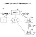
図1は、本実施形態の処理実行システム500の概略的な特徴を説明する図の一例である。ネットワーク400を介して、MFP(Multi Function Peripheral)201、配信サーバ100、及び、サービス提供装置(以下、区別する場合、サービス提供装置1,2という)300が通信可能に接続されている。
FIG. 1 is an example of a diagram illustrating schematic features of the
(i) ユーザはMFP201を操作して1つ以上の処理を含むワークフローを定義する。例えば、「PDF変換→電子メール送信」というワークフローを設定したとする。この一連の処理がフロー定義情報となる。フロー定義情報には次に実行される処理がカレントポイント(特許請求の範囲の次処理に相当する)として指示されている。開始前はPDF変換がカレントポイントである。MFP201はフロー定義情報とジョブデータ(画像データなど)を配信サーバ100に送信する。
(i) The user operates the
(ii) 配信サーバ100はフロー定義情報を解析して、フロー定義情報の各処理にサービス提供装置を対応づけてフロー定義情報を更新する。PDF変換、電子メール送信をそれぞれ行うサービス提供装置1,2が決定される。なお、配信サーバが処理を実行する場合もある。
(ii) The
(iii) 配信サーバ100は、カレントポイントが設定された処理を行うサービス提供装置1にフロー定義情報とジョブデータを送信する。
(iii) The
(iv) サービス提供装置1はフロー定義情報を解析して自機が実行対象機器か否かを判定し、自機が実行対象機器の場合はカレントポイントにて指示される処理を実行する。そして、サービス提供装置1はフロー定義情報の次の処理にカレントポイントを更新して、次に処理を行うサービス提供装置2にフロー定義情報とジョブデータを送信する。
(iv) The
(v) サービス提供装置2はフロー定義情報を解析して自機が実行対象機器か否かを判定し、自機が実行対象機器の場合はカレントポイントにて指示される処理を実行する。そして、サービス提供装置2はフロー定義情報の次の処理にカレントポイントを更新して、次に処理を行うサービス提供装置にフロー定義情報とジョブデータを送信する。この例では、次に行う処理がないのでワークフローはここで終了する。
(v) The
したがって、配信サーバ100は最初にフロー定義情報とジョブデータを送信した後、各サービス提供装置との間の通信量を抑制できるので(主に実行結果の受信を行う)、配信サーバ100に処理負荷や配信サーバ100が接続されたネットワークに通信負荷が集中することを抑制できる。
Therefore, since the
〔構成例〕
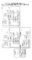
図2は、処理実行システム500のシステム構成図の一例を示す。配信サーバ100を中心に、ネットワーク400を介してワークフロー実行要求装置200と1台以上のサービス提供装置300が接続されている。配信サーバ100が中心にあるのは処理上の位置を示すにすぎず、ワークフロー実行要求装置200とサービス提供装置300も互いにネットワーク400を介して接続されている。
[Configuration example]
FIG. 2 shows an example of a system configuration diagram of the
ネットワーク400は、LAN、又は、複数のLANがルータなどを介して接続されたWANである。また、ファイアウォールを考慮しなければインターネットを含んでいてよい。ネットワーク400は有線で構築されていてもよいし、一部又は全てを無線LAN(IEEE802.11b/a/g/n等)で構築されていてもよい。さらに、ネットワーク400は携帯電話網、WiMAX網、PHS網などの移動体向けに構築された通信網を含む。なお、処理実行システム500の各装置が無線LANのアドホックモードなどで1対1で通信しても、ネットワーク400に含めることとする。
The
ワークフロー実行要求装置200はワークフローの実行を配信サーバ100に要求する装置である。例えば、MFP201、携帯端末202、クライアント端末203が図示されているが、通信機能を備えた情報処理装置はワークフロー実行要求装置200になりうる。ワークフロー実行要求装置200は処理実行システム500に1台以上存在する。MFP201は、コピー機、スキャナー、プリンタ、ファックス装置など画像を形成する機能を備えた装置である。MFP201はこのうち1つ以上の機能を有していればよい。MFP201は、例えば原稿をスキャンして作成した画像データをジョブデータとして配信サーバ100に送信すると共にフロー定義情報を送信し、配信サーバ100にワークフローの実行を要求する。
The workflow
携帯端末202は、携帯電話、スマートフォン、タブレット端末、PDA(Personal Digital Assistant)、デジタルカメラなど、ユーザが携帯又は所持する端末である。例えば、携帯電話のカメラやデジタルカメラで撮影した画像データをジョブデータとして配信サーバ100に送信すると共にフロー定義情報を送信し、配信サーバ100にワークフローの実行を要求する。
The
クライアント端末203はノートPC(Personal Computer)、デスクトップPC、ワークステーション、テレビ会議端末などユーザが使用する情報処理装置である。例えば、アプリケーションが作成したアプリケーションデータ、Webから取得したWebデータをジョブデータとして配信サーバ100に送信すると共にフロー定義情報を送信し、配信サーバ100にワークフローの実行を要求する。
The
なお、ワークフロー実行要求装置200は、ユーザが直接、操作する装置であるとするが、ジョブデータはユーザが直接、操作する装置が作成したり記憶している必要はない。例えば、クライアント端末が、NAS(Network Attached Storage)や他の装置に記憶されているジョブデータを指定して、NAS等から配信サーバ100に送信する(配信サーバ100が読みに行く)ことも可能である。
Although the workflow
配信サーバ100は、PC、サーバ装置、シンクライアント等の情報処理装置である。MFPが配信サーバとなることも可能である。例えば、MFP201からジョブデータとして画像データとフロー定義情報を受信した場合、フロー定義情報に従い配信処理を実行する。なお、配信サーバ100は1台存在すればよいが、1台以上存在してもよい。配信サーバ100がサービス提供装置300としての機能を有することも可能である。
The
サービス提供装置300は、PC、サーバ装置、シンクライアント等の情報処理装置である。MFPがサービス提供装置300となることも可能である。サービス提供装置300はフロー定義情報を解析して、処理を実行する。例えば、配信サーバ100からジョブデータとして画像データとフロー定義情報を受信した場合、フロー定義情報に従い画像データにOCR処理を施したり、電子メールで送信したりする。サービス提供装置300は、1台以上存在する。また、1台で複数の処理を行う場合もある。
The
配信サーバ100とサービス提供装置300はいずれもフロー定義情報で定義された処理を実行するので、両者を区別しない場合、単に「装置」という場合がある。
Since both the
図3は、MFP201としてのワークフロー実行要求装置200のハードウェア構成図の一例を示す。MFP201は、コントローラ130と、オペレーションパネル125と、ファクシミリコントロールユニット(FCU)126と、撮像部127及び印刷部128を有する。
FIG. 3 shows an example of a hardware configuration diagram of the workflow
コントローラ130は、CPU114と、ASIC116と、NB(ノースブリッジ)115と、SB(サウスブリッジ)117と、MEM−P(システムメモリ)111と、MEM−C(ローカルメモリ)112と、HDD(ハードディスクドライブ)113と、メモリカードスロット123と、NIC(ネットワークインタフェースコントローラ)118と、USBデバイス119と、IEEE1394デバイス121と、セントロニクスデバイス122とを有する。
The
CPU114は、種々の情報処理を実行するためのICであり、OSやプラットホーム上で、アプリケーションをプロセス単位で並列的に実行する。ASIC116は、画像処理用のICである。NB115は、CPU114とASIC116を接続するためのブリッジである。SB117は、NB115と周辺機器等を接続するためのブリッジである。ASIC116とNB115は、例えばAGP(Accelerated Graphics Port)を介して接続されている。
The
MEM−P111は、NB115に接続されたメモリである。MEM−C112は、ASIC116に接続されたメモリである。HDD113は、ASIC116に接続されたストレージであり、画像データ蓄積・文書データ蓄積・プログラム蓄積・フォントデータ蓄積・フォームデータ蓄積等を行うために使用される。HDD113には種々のアプリケーション(コピーアプリ、スキャナアプリ、プリンタアプリ、ファックスアプリ等)及びプログラム131が記憶されている。プログラム131はユーザによるワークフローの設定を受け付け、フロー定義情報等を作成するためのものである。
The MEM-
メモリカードスロット123は、SB117に接続され、メモリカード124をセット(挿入)するために使用される。メモリカード124は、USBメモリ、SDメモリ等のフラッシュメモリであり、プログラム131を配布するために使用される。また、プログラム131は所定のサーバからMFP201にダウンロードすることで配布することもできる。
The
NIC118は、ネットワーク400等を介してMACアドレス等を使用したデータ通信を行うためのコントローラである。USBデバイス119は、USB規格に準拠したシリアルポートを提供するためのデバイスである。IEEE1394デバイス121は、IEEE1394規格に準拠したシリアルポートを提供するためのデバイスである。セントロニクスデバイス122は、セントロニクス仕様に準拠したパラレルポートを提供するためのデバイスである。NIC118と、USBデバイス119と、IEEE1394デバイス121と、セントロニクスデバイス122と、PCI(Peripheral Component Interconect)バスを介してNB115とSB117に接続されている。
The
オペレーションパネル125は、ユーザがMFP201に入力を行うためのハードウェア(操作部)であると共に、MFP201がメニュー画面を表示するハードウェア(表示部)である。オペレーションパネル125は、ASIC116に接続されている。FCU126と、撮像部127と、印刷部128は、PCI(Peripheral Component Interconect)バスを介してASIC116に接続されている。
The
撮像部127は、コンタクトガラスに載置された原稿を光学的に走査して、その反射光をA/D変換して画像処理を施し、カラー又はモノクロのデジタルデータ(以下、画像データという)を生成する。
The
印刷部128は、例えばタンデム型の感光ドラムを有し、上記の画像データやユーザPCから受信したPDLデータに基づきレーザビームを変調し感光ドラムを走査して潜像を形成する。潜像にトナーを付着して現像した1ページ毎の画像を用紙に熱と圧力で転写する。このような電子写真方式のプロッタに限られず、液滴を吐出して画像を形成するインクジェット型のプロッタエンジンでもよい。
The
FCU126は、NIC118を介してネットワーク400に接続し例えばT.37,T.38の規格に対応した通信手順、又は、公衆通信網に接続し例えばG3、G4規格に対応した通信手順、に従い画像データの送受信を行う。また、MFP201の電源がOFFのときに画像データを受信しても、印刷部128を起動して画像データを用紙に印刷することができる。
The
図4は、配信サーバ100のハードウェア構成図の一例を示す。配信サーバ100は、バスに接続された、CPU301、ROM302、RAM303、HDD304、ディスプレイ320が接続されたグラフィックボード305、キーボード・マウス306、メディアドライブ307、及び、ネットワーク通信部308を有する。CPU301はHDD304に記憶されたプログラム310をRAM303に展開して実行し、各部品を制御して入出力を行ったり、データの加工を行ったりする。ROM302にはBIOSや、ブートストラップローダをHDD304からRAM303に読み出すスタートプログラムが記憶されている。ブートストラップローダは、OSをHDD304からRAM303に読み出す。
FIG. 4 shows an example of a hardware configuration diagram of the
HDD304は、不揮発性のメモリであればよくSSD(Solid State Drive)などでもよい。HDD304はOS、デバイスドライバ、及び、後述する機能を提供するプログラム310を記憶している。ディスプレイ320にはプログラムが指示し、グラフィックボード305が作成したGUI画面が表示される。
The
キーボード・マウス306はユーザの操作を受け付ける入力装置である。メディアドライブ307はコンパクトディスク、DVD及びブルーレイディスクなどの光学メディアにデータを読み書きする。また、フラッシュメモリなどのメモリカードにデータを読み書きしてもよい。ネットワーク通信部308は、例えばLANに接続するためのイーサネット(登録商標)カードである。TCP/IP(UDP/IP)やアプリケーション層のプロトコルの処理はOSやプログラム310が行う。アプリケーション層のプロトコルは各種あるが、例えばSNMP(Simple Network Management Protocol)、HTTP、FTP、SMB(Server Message Block)等がある。
A keyboard /
プログラム310は、インストール可能な形式又は実行可能な形式のファイルで、コンピュータで読み取り可能な記録メディアに記録して配布される。また、プログラム310は、不図示のサーバからインストール可能な形式又は実行可能な形式のファイルで配布される。
The
〔フロー定義情報〕
図5は、フロー定義情報の一例を説明する図の一例である。図5(a)はワークフロー実行要求装置200が配信サーバ100に送信するフロー定義情報であり、図5(b)は配信サーバ100がサービス提供装置300に送信するフロー定義情報である。
[Flow definition information]
FIG. 5 is an example of a diagram illustrating an example of the flow definition information. FIG. 5A shows the flow definition information that the workflow
ユーザは、ワークフロー実行要求装置200で配信サーバ100にアクセスし配信サーバ100から画面データを受信する。画面データには、ワークフローを定義するためのメニューが表示され、ユーザは自身が所望する複数の処理について、処理の順番と処理内容(処理に必要な条件。例えば、電子メールアドレスの送信先、FAXの送信先、ドキュメントボックスの記憶先、印刷条件など)を設定することでワークフローを定義する。各処理において設定が必要な事項は決まっているので、画面にはユーザが選択した処理に応じて必要な処理内容を設定するメニューが表示される。例えば、PDF変換やメール配信では以下のような処理内容が設定される。
処理1.PDF変換
ドキュメントデータ:ABC.doc
処理2.メール配信
宛先アドレス:123456@abc.com
件名:会議資料
ドキュメントデータ:処理1から取得
ユーザがワークフローの設定を完了すると、ワークフロー実行要求装置200が図5(a)のようなフロー定義情報を作成する。なお、図のフロー定義情報は説明上重要でない記載が省略されている。
The user accesses the
Subject: Meeting material document data: acquired from
フロー定義情報は、例えばXMLで記述されている。<flows>から</flows>までが1つのワークフローを定義している。また、<flow>から</flow>はワークフローの手順を定義している。 The flow definition information is described in XML, for example. One workflow is defined from <flows> to </ flows>. Also, <flow> to </ flow> define workflow procedures.
1つの処理は1つの<plugin id>タグ単位に記述され、何の処理が行われるかが記述されている。例えば、「plugin id="ToSMTP"」は電子メールで送信する処理を意味しており、「type="output"」はデータの処理タイプが出力であることを意味している。「displayName="メール配信" 」は操作パネルなどユーザが目視する際に表示される処理名である。「plugin id="PDFConverter"」はジョブデータをPDFに変換する処理を意味しており、「type="filter"」はデータの処理タイプが変換であることを意味している。「displayName="PDF変換" 」は操作パネルなどユーザが目視する際に表示される処理名である。 One process is described in units of one <plugin id> tag and describes what process is performed. For example, “plugin id =“ ToSMTP ”” means processing to send by e-mail, and “type =“ output ”” means that the data processing type is output. “DisplayName =“ mail delivery ”” is a process name displayed when the user visually checks the operation panel or the like. “Plugin id =“ PDFConverter ”” means processing for converting job data into PDF, and “type =“ filter ”” means that the processing type of data is conversion. “DisplayName =“ PDF conversion ”” is a process name displayed when the user visually checks the operation panel or the like.
また、<nextPlugin id>タグは処理の順番を指示するタグである。つまり、PDF変換の次の処理は、メール配信であることが定義されている。これにより、サービス提供装置300は次の処理を決定できる(正確には図5(b)に示すように次のサービス提供装置を特定できる)。
The <nextPlugin id> tag is a tag that indicates the order of processing. That is, it is defined that the next process of PDF conversion is mail delivery. As a result, the
<start_point>タグは、ワークフローが開始される最初の処理を定義している。すなわち、ユーザがワークフローの最初に実行するように定義した処理が定義される。 The <start_point> tag defines the first process for starting the workflow. That is, a process defined by the user to be executed at the beginning of the workflow is defined.
図5(a)のフロー定義情報によれば、<start_point>タグから最初の処理がPDF変換であり、PDF変換の次の処理がメール配信であることが分かる。 According to the flow definition information in FIG. 5A, it can be seen from the <start_point> tag that the first process is PDF conversion, and the next process after PDF conversion is mail delivery.
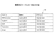
配信サーバ100は図5(a)のフロー定義情報を解析して、<plugin id>タグ単位にproceed属性を追加し、フロー定義情報に<current_point>タグを追加する。配信サーバ100は<plugin id>タグ毎に、plugin idの処理が可能なサービス提供装置が対応づけられた後述する機器決定テーブル44を有している。配信サーバ100は機器決定テーブル44を参照して、例えばメール配信を行うのは「machineID_A」であり、PDF変換を行うのは「machineID_B」であると決定する。図5(b)は配信サーバ100が更新したフロー定義情報の一例である。
The
なお、各処理を行うサービス提供装置300の決定まで含めてワークフロー実行要求装置200が行ってもよい。ワークフロー実行要求装置200が機器決定テーブル44を有するか又はアクセス可能であればよいので、機器の決定はワークフロー実行要求装置200やサービス提供装置300が行うことも可能である。
The workflow
図5(c)は<current_point>タグについて説明する図の一例である。<current_point>タグはワークフローにおいて現時点において処理すべき処理、すなわち次に処理すべき処理を示す。配信サーバ100は、<start_point>タグを参照して最初に行う処理を決定し、図5(b)のようにPDF変換が次に処理すべき処理であることをフロー定義情報に記述する。なお、<current_point>タグの処理をカレントポイントの処理と称する。<current_point>タグはワークフロー実行要求装置200が配信サーバに送信する時点で含まれていていてもよい。この場合、<current_point>タグは<start_point>タグと同じになる。
FIG. 5C is an example of a diagram for explaining the <current_point> tag. The <current_point> tag indicates a process to be processed at the current time in the workflow, that is, a process to be processed next. The
サービス提供装置300はproceed属性と<current_point>タグを参照して自機が処理を行うか否かを判定する。また、処理を行った場合は、<current_point>タグを更新して、次のサービス提供装置にフロー定義情報とジョブデータを送信する。例えば、PDF変換が完了したら、<current_point>タグは次のように更新される。
<current_point>
<plugin id="ToSMTP" />
</current_point>
また、図5(a)(b)では<nextPlugin id>タグに1つのplugin idしか記述されていないが、ユーザが設定したワークフローによっては平行に処理が可能となる場合もある。例えば、ジョブデータを電子メールで送信すると共にドキュメントボックスに記憶するような場合、電子メールの送信とドキュメントボックスの送信は平行して実行可能である。このようなワークフローでは、<nextPlugin id>タグに2つ以上のplugin idが記述される場合がある。この場合、配信サーバ100は、<current_point>タグに"ToSMTP"と記述されたフロー定義情報と、"DocBox(ドキュメントボックス)"と記述されたフロー定義情報を作成し、サービス提供装置300に送信する。
The
<current_point>
<plugin id = "ToSMTP"/>
</ current_point>
In FIGS. 5A and 5B, only one plugin id is described in the <nextPlugin id> tag. However, depending on the workflow set by the user, parallel processing may be possible. For example, when job data is transmitted by e-mail and stored in a document box, transmission of the e-mail and transmission of the document box can be performed in parallel. In such a workflow, two or more plugin ids may be described in the <nextPlugin id> tag. In this case, the
〔機能ブロック例〕
図6はワークフロー実行要求装置200、配信サーバ100、及び、サービス提供装置300の機能ブロック図の一例を示す図である。
[Function block example]
FIG. 6 is a diagram illustrating an example of a functional block diagram of the workflow
ワークフロー実行要求装置200は、フローデータ送信部11、フロー定義受付部12、及び、フロー定義画面受信部13を有する。フロー定義画面受信部13は、配信サーバ100にアクセスしてワークフローを定義するための画面データを受信する。なお、配信サーバ100のIPアドレス又はURLなどはワークフロー実行要求装置200にとって既知である。画面データは例えばXMLで記述されている。フロー定義画面受信部13はXMLとXSLTスタイルシートを受信してHTMLに変換してオペレーションパネル125等に表示する。フロー定義受付部12は、ユーザによるワークフローの設定を受け付け、フロー定義情報を作成する。フローデータ送信部11はフロー定義情報と、フロー定義情報で指定されたジョブデータを配信サーバ100に送信する。なお、ジョブデータは、ユーザが明示的にファイル名を指定して指示される場合と、原稿のスキャンやカメラによる撮影などのように、ワークフローの中で作成される場合がある。本実施例では説明を容易にするため前者の状況にて説明する。
The workflow
配信サーバ100は、1つ以上のプラグイン21、フロー制御部22、ジョブ制御部23、及び、配信機能部24を有している。配信機能部24は、配信サーバ100がワークフローを準備・支援するための機能であり、ログ記録部41、機器決定部42、及び、画面データ送信部43を有している。画面データ送信部43は、ワークフロー実行要求装置200からの要求に応じて、画面データDB45から画面データを読み出し、ワークフロー実行要求装置200に送信する。
The
機器決定部42は、ワークフロー実行要求装置200との通信の中で機器決定テーブル44を参照して各処理を実行する機器を決定する。例えば、ユーザが設定したフロー定義情報を画面データ送信部43が受信し、最終的なワークフローの確認画面を送信する際に、機器を決定すればよい。または、ジョブ受信部33が受信したフロー定義情報に対し、機器を決定してもよい。
The device determining unit 42 refers to the device determination table 44 during communication with the workflow
図7は機器決定テーブルの一例を示す図である。処理を実行可能なサービス提供装置300の機器IDとIPアドレスが登録されている。IPアドレスは不図示のDHCPサーバにより割り当てられ、機器IDが分かればIPアドレスも特定できるようになっている。または、サービス提供装置300に固定のIPアドレスが付与される場合は、IPアドレスを機器IDとして用いてもよい。機器決定部42は、plugin idに基づきその処理を実行可能な機器IDを特定してproceed属性として追加する。1つのplugin idに複数の機器IDが登録されている場合、例えばサービス提供装置300から収集した処理負荷の低いサービス提供装置を選んでもよいし、同じネットワークアドレスのサービス提供装置300を優先して選んでもよい。
FIG. 7 is a diagram illustrating an example of the device determination table. The device ID and IP address of the
また、ユーザがワークフローの実行開始操作を行う前に、配信サーバ100は例えばサービス提供装置300の起動の有無を判断し、起動しているサービス提供装置300を処理に割り当ててもよい。これにより、ユーザから実行開始操作を受け付けた後に、ワークフローの大部分が実行できない状況となることを抑制できる。
Further, before the user performs a workflow execution start operation, the
図6に戻り、ログ記録部41は、ワークフローのログを記録する。サービス提供装置300は自機の処理が終了すると実行結果を配信サーバ100に送信するので、ログ記録部41はワークフロー単位で、各処理を実行した機器の識別情報、開始時刻、終了時刻及び処理が完了したか失敗したか等を記録する。配信サーバ100が実行した場合は自機のログ記録部41が実行結果を記録する。
Returning to FIG. 6, the log recording unit 41 records a workflow log. Since the
ジョブ制御部23は、ワークフローの各処理の実行を制御する。まず、ジョブ受信部33は、他の装置(配信サーバ100はワークフロー実行要求装置200とサービス提供装置。サービス提供装置300は配信サーバ100又は他のサービス提供装置300)からフロー定義情報とジョブデータを受信しジョブキュー35に蓄積する。1つのジョブは、1つのPlugin idが付与された1つの処理に相当する。
The
ジョブ受信部33は、いったんジョブキュー35に記憶したワークフローのフロー定義情報とジョブデータを自機で処理を行う必要があるか否かを判定する。すなわち、自機のマシンID36が少なくとも1つのProceed属性に登録されているか否かを判定する。
The
自機のマシンID36がProceed属性に登録されていない場合、ジョブ転送部32はフロー定義情報とジョブデータをサービス提供装置300に送信する。このサービス提供装置300は<current_point>の処理を受け持つサービス提供装置であることが好ましいが、<current_point>の処理を受け持たないサービス提供装置に送信しても転送されるので不都合は少ない。
When the
自機のマシンID36がProceed属性に登録されている場合、ジョブ実行部31がフロー定義情報とジョブデータをジョブキュー35から読み出して処理を実行する。ジョブ実行部31は、<current_point>を確認して、<current_point>の処理を行う配信サーバ100又はサービス提供装置300を確認する。自機が<current_point>の処理を行う機器の場合、フロー制御部22にフロー定義情報とジョブデータを出力する。自機が<current_point>の処理を行う機器でない場合、ジョブ実行部31はジョブ転送部32にフロー定義情報とジョブデータを転送させる。転送先は、好ましくは<current_point>の処理を受け持つサービス提供装置300である。
When the
フロー制御部22は、フロー定義情報に沿ってプラグイン21を選択して処理を実行する。プラグイン21は、これまで説明したPDF変換を行うもの、電子メールを送信するもの、OCR処理を行うもの、翻訳を行うものなどである。プラグイン21は共通のプラットホーム上で動作可能になっており、配信サーバ100やサービス提供装置は1つのプラグイン21を独立に追加したり、削除することができる。プラグイン同士は互いの処理には関与しない。なお、このようなプラグイン21に限られずアプリケーションプログラムにより処理してもよい。
The
フロー制御部22は、<current_point>の処理を確認して、その処理を行うプラグイン21を呼び出すと共にジョブを実行させる。ジョブが正常に完了すればフロー制御部22は、<current_point>タグの処理を更新する。ジョブ実行部31はフロー定義情報とジョブデータをジョブキュー35に記憶する。
The
ジョブ検知部34は、ジョブキュー35にジョブが入力されたことを検知する。すなわち、プラグイン21が1つの処理を実行することで作成されたジョブデータがジョブキュー35に記憶されると、ジョブ検知部34が検知する。そして、ジョブ実行部31等が同様の処理を繰り返し行う。
The
図6に示すように、サービス提供装置300は、1つ以上のプラグイン21、フロー制御部22及びジョブ制御部23、を有している。すなわち、配信機能部24を有さないが、その他の機能は配信サーバ100と同様である。これは、ワークフローの実行手順については、サービス提供装置300と配信サーバ100とで同様となることを意味しており、サービス提供装置300の開発コストを低減したり、サービス提供装置300と配信サーバ100を柔軟に切り替えることが可能であることを示す。
As illustrated in FIG. 6, the
〔動作手順〕
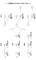
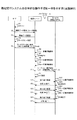
図8は、処理実行システム500の全体的な動作手順の一例を示す図である。
S1:ユーザはMFP201にログインする。ログインについては後述するが、ユーザ名とパスワードの入力、ICカードの読み取りなどでログインすればよい。
S2:ユーザの操作により、MFP201はワークフローの画面データを配信サーバ100に要求する。この時、ユーザ情報も送信される。
S3:配信サーバ100の画面データ送信部43は画面データをMFP201に送信する。
S4:ユーザがワークフローの内容をMFP201に設定すると、フロー定義受付部12がワークフローのフロー定義情報を作成する。
S5:ユーザが最終的なワークフローの実行開始操作を行うと、フローデータ送信部11はフロー定義情報とジョブデータを配信サーバ100に送信する。なお、配信サーバ100又はMFP201はフロー定義情報とジョブデータを受信する前に、各処理を実行する機器を決定しているものとする。
S6:配信サーバ100のジョブ受信部33はジョブキュー35にフロー定義情報とジョブデータを記憶し、フロー定義情報を解析する。この解析は、自機が処理を行う機器として記述されているか否かと、カレントポイントが自機の処理を示しているか否かの2つである。
S7:解析の結果、自機が処理を行う場合は、フロー制御部22がプラグイン21を使用して自機に割り当てられた処理を実行する。
S8:フロー制御部22は、カレントポイントを次の処理に変更して、フロー定義情報を更新する。
S9:次に、ジョブ実行部31はフロー定義情報を解析して、次の処理を行うサービス提供装置300を特定する。
S10:ジョブ転送部32は次の処理を行うサービス提供装置1にフロー定義情報とジョブデータを送信する。
S11:ジョブ制御部23は自機が行った処理の実行結果を配信サーバ100に送信する。ここでは配信サーバ100が処理を行ったので、ログ記録部41に実行結果を出力すればよい。
S12〜S17:以降、サービス提供装置1が行う処理手順は配信サーバ100が行った処理手順と同様になる。
S18〜S22:サービス提供装置2が行う処理手順は配信サーバ100が行った処理手順と同様になる。
このように、ワークフローの処理手順については装置間の処理手順を同じにすることができる。
[Operation procedure]
FIG. 8 is a diagram illustrating an example of an overall operation procedure of the
S1: The user logs in to the
S2: The
S3: The screen
S4: When the user sets the content of the workflow in the
S5: When the user performs the final workflow execution start operation, the flow
S6: The
S7: As a result of the analysis, if the own device performs processing, the
S8: The
S9: Next, the job execution unit 31 analyzes the flow definition information and identifies the
S10: The
S11: The
S12 to S17: Thereafter, the processing procedure performed by the
S18 to S22: The processing procedure performed by the
As described above, the processing procedure between the apparatuses can be made the same for the processing procedure of the workflow.
図9は、配信サーバ100又はサービス提供装置が処理を実行する際の手順を示すフローチャート図の一例である。図9は図8のS6〜11の詳細な手順になっている。
FIG. 9 is an example of a flowchart illustrating a procedure when the
まず、ジョブ受信部33がフロー定義情報とジョブデータを受信して、ワークフロー実行要求を受け付ける(S10)。
First, the
ジョブ受信部33はフロー定義情報のproceed属性に自機のマシンIDが登録されているか否かに基づき自機が実行対象機器か否かを判定する(S20)。
The
自機が実行対象機器でない場合(S20のNo)、他のサービス提供装置が実行できるように、ジョブ転送部32がフロー定義情報とジョブデータを転送する(S100)。
If the own device is not the execution target device (No in S20), the
自機が実行対象機器の場合(S20のYes)、ジョブ実行部31はカレントポイントの処理が、自機が行う処理か否かを判定する(S30)。 When the own device is an execution target device (Yes in S20), the job execution unit 31 determines whether or not the current point process is a process performed by the own device (S30).
カレントポイントの処理を行うのが自機でない場合(S30のNo)、他のサービス提供装置300が実行できるように、ジョブ転送部32がフロー定義情報とジョブデータを転送する(S100)。ワークフローの全体が終了した場合は、転送しなくてよい。また、終了したことを配信サーバ100に送信することが好ましい。
When the current point is not processed by the own device (No in S30), the
カレントポイントの処理を行うのが自機の場合(S30のYes)、ジョブ実行部31はフロー制御部22に処理を依頼する(S40)。
When the current point is processed by the own machine (Yes in S30), the job execution unit 31 requests the
フロー制御部22はカレントポイントを確認して、自機が行う処理を特定し、該当するプラグイン21を呼び出すなどして処理を実行する(S50)。プラグイン21は処理の実行結果をフロー制御部22に返す。
The
フロー制御部22は、処理が正常に終了したか、又は、プラグイン21がエラーの発生を明示的に通知したり応答がない等により正常に終了しなかったかどうかを判定する(S60)。
The
正常に終了しない場合(S60のNo)、フロー制御部22はリトライの上限回数に達したか否かを判定する(S90)。リトライの上限回数に達していない場合(S90のNo)、処理はステップS50に戻り、プラグイン21が再度同じ処理を行う。
When the process is not completed normally (No in S60), the
リトライの上限回数に達した場合(S90のYes)、処理はステップS80に移動し、ジョブ制御部23は実行結果を送信する(S80)。この場合の実行結果は処理のplugin IDと正常終了しなかったという情報を含む。
If the upper limit number of retries has been reached (Yes in S90), the process moves to step S80, and the
正常に終了した場合(S60のYes)、フロー制御部22はカレントポイントを変更することで、フロー定義情報を更新する(S70)。
When the process ends normally (Yes in S60), the
次いで、ジョブ制御部23は実行結果を送信する(S80)。この場合の実行結果は処理のplugin IDと正常終了したという情報を含む。
Next, the
この後、処理は、ステップS30に戻り、必要であればフロー制御部22が再度、処理を行う。
Thereafter, the process returns to step S30, and the
以上説明したように、本実施例の処理実行システム500は、配信サーバ100と各サービス提供装置300にワークフローの処理機能を持たせることで、ジョブを次々と転送することができる。このため、処理毎に配信サーバ100にジョブデータ等を戻す必要がなく、配信サーバ100とサービス提供装置との間のやり取りを少なくして効率的にジョブ処理を行うことができる。
As described above, the
本実施例では、ファイアウォール越しにサービス提供装置300が存在する処理実行システム500について説明する。
In this embodiment, a
図10は、処理実行システム500のシステム構成図の一例を示す。なお、本実施例において、実施例1において同一の符号を付した構成要素は同様の機能を果たすので、主に本実施例の主要な構成要素についてのみ説明する場合がある。
FIG. 10 shows an example of a system configuration diagram of the
処理実行システム500はファイアウォール600を介してオフィス側と外部とに分かれている。オフィス側の構成は実施例1とほぼ同様になっている。外部側にはネットワーク(インターネット)越しに1台以上のサービス提供装置300が存在する。サービス提供装置は実施例1と同様にフロー制御部22、ジョブ制御部23及び1つ以上のプラグイン21を有している。
The
このようなシステム形態ではユーザがオフィス側に存在するので、外部のサービス提供装置300が処理したジョブデータをオフィス側の配信サーバ等が取得する場合、ファイアウォール600を超える必要がある。外部の装置が通信の契機となってファイアウォール600を超えることは困難なので、配信サーバ100が外部のサービス提供装置300を監視する。監視により、配信サーバ100が外部のサービス提供装置300からジョブデータ等を受信することを可能とする。
In such a system configuration, since the user exists on the office side, when the office-side distribution server or the like acquires job data processed by the external
監視とは、配信サーバ100が定期的に外部のサービス提供装置300に実行結果を確認すること(外部からの応答を受け取れる通信状態にすること)をいう。ファイアウォール600のアクセス制御には例えばパケットフィルタリング、ステートフルインスペクションなどがあるが、これらでは、管理者等がオフィス側から送信したパケットの宛先IPアドレスからの応答(外部からの通信の送信元IPアドレスが、オフィスからの通信で設定した宛先IPアドレスになっている)は通過を許可するという設定が可能である。このような設定がされたファイアウォール600であれば、オフィス側の配信サーバ100が送信したパケットに対する応答としてフロー定義情報とジョブデータを受信できる。
Monitoring means that the
〔フロー定義情報の作成〕
本実施例では、実施例1とは別の態様でフロー定義情報の作成が必要になる。これは、配信サーバ100が外部のサービス提供装置300を監視するフロー定義情報を必要とするためである。
[Create flow definition information]
In this embodiment, it is necessary to create flow definition information in a mode different from that in the first embodiment. This is because the
図11は、フロー定義情報の作成を模式的に説明する図の一例である。図11(a)の更新前のフロー定義情報は、以下のようになっている。なお、処理内容はどのようなものでもよく、一部の処理を外部のサービス提供装置300が行えばよい。
処理1(マル1):配信サーバ
処理2(マル2):外部のサービス提供装置C1
配信サーバ100は、処理1を実行後、フロー定義情報を更新するが(カレントポイントを次の処理に変更する)、更新されるフロー定義情報とは別にフロー定義情報を作成する。
FIG. 11 is an example of a diagram for schematically explaining creation of flow definition information. The flow definition information before update in FIG. 11A is as follows. The processing content may be anything, and part of the processing may be performed by the external
Process 1 (Mal 1): Distribution server process 2 (Mal 2): External service providing device C1
The
作成されるフロー定義情報は、配信サーバ100が外部のサービス提供装置C1を監視するフロー定義情報である。後者のフロー定義情報は以下のようにして作成する。配信サーバ100はフロー定義情報を複製し、<plugin id>タグに
<plugin id="Monitor" … proceed= " machineID_A(配信サーバ)" />
を追加する。すなわち、監視する処理を配信サーバ100が行うことが追加される。監視する処理を行う装置は、予め定められており(この場合は配信サーバ)、予め定められた装置のマシンIDが<plugin id>タグのproceed属性に記述される。
The created flow definition information is flow definition information for the
<plugin id = "Monitor"… proceed = "machineID_A (distribution server)"/>
Add That is, it is added that the
また、配信サーバ100は、<current_point>の記述を<plugin id="Monitor" />に変更する。すなわち、次の処理が監視であることを示すように変更する。
Further, the
このような更新により、図11(a)の更新後に示すように、処理2(マル2)のフロー定義情報は外部のサービス提供装置C1に送信され、処理A(マルA)のフロー定義情報は配信サーバ100により実行される。なお、処理A(マルA)のフロー定義情報は監視が終了すると、次の処理が記述されていないので破棄される。
By such an update, as shown after the update in FIG. 11A, the flow definition information of the process 2 (Mal 2) is transmitted to the external service providing apparatus C1, and the flow definition information of the process A (Mal A) is It is executed by the
以下、フロー制御部22が更新したフロー定義情報をオリジナルのフロー定義情報といい、配信サーバが作成したフロー定義情報を監視用のフロー定義情報という。
Hereinafter, the flow definition information updated by the
図11(b)の更新前のフロー定義情報は、以下のようになっている。
処理1:配信サーバ
処理2:外部のサービス提供装置C1
処理3:配信サーバ
処理2までは図11(a)と同様だが、次に、配信サーバ100が処理3を行う。図11(a)の更新後のフロー定義情報に示したように、外部のサービス提供装置C1は処理2を実行し、外部のサービス提供装置C1の処理を、配信サーバ100が監視する。外部のサービス提供装置C1は処理2の実行後、フロー定義情報を更新してジョブデータと共に、監視している配信サーバ100に送信する。したがって、配信サーバ100はファイアウォール600越しに更新されたフロー定義情報とジョブデータを受信できる。外部のサービス提供装置C1が更新したフロー定義情報の<current_point>には配信サーバ100が処理3を行うことが記述されているので、配信サーバ100は実施例1と同様にワークフローの処理を実行できる。
The flow definition information before update in FIG. 11B is as follows.
Process 1: Distribution server process 2: External service providing device C1
Process 3: Distribution Server The process up to
図11(c)の更新前のフロー定義情報は、以下のようになっている。
処理1:配信サーバ
処理2:外部のサービス提供装置C1
処理3:内部のサービス提供装置1
処理2までは図11(a)と同様だが、次に、オフィス側のサービス提供装置1が処理3を行う。この場合も、外部のサービス提供装置C1を監視している配信サーバ100はファイアウォール600越しに更新されたフロー定義情報とジョブデータを受信する。外部のサービス提供装置C1が更新したフロー定義情報の<current_point>にはオフィス側のサービス提供装置1が処理3を行うことが記述されている。このため、配信サーバ100はフロー定義情報を解析して、自機が処理を行う装置ではないので、フロー定義情報とジョブデータを、オフィス側のサービス提供装置1に転送する。
The flow definition information before update in FIG. 11C is as follows.
Process 1: Distribution server process 2: External service providing device C1
Process 3: Internal
The processing up to
このように、ファイアウォール600側の配信サーバ100が外部のサービス提供装置の処理を監視するフロー定義情報を作成することで、ファイアウォール600を跨いでワークフローを実行することが可能になる。
In this way, the
なお、配信サーバ100による監視はワークフローの一部なので処理を実行するのはプラグイン21とすることができる。したがって、配信サーバ100に機能を追加する場合はもちろん、サービス提供装置300に監視機能を追加することも容易である。当然ながら、プラグイン21とは別に監視用の機能がインストールされてもよい。
Since monitoring by the
〔動作手順〕
図12は、処理実行システム500の全体的な動作手順を一例を示す図である。ここでは図11(a)のワークフローを処理する場合を例に説明する。
S1:ユーザはMFP201にログインする。ログインについては後述するが、ユーザ名とパスワードの入力、ICカードの読み取りなどでログインすればよい。
S2:ユーザの操作により、MFP201はワークフローの画面データを配信サーバ100に要求する。この時、ユーザ情報も送信される。
S3:配信サーバ100の画面データ送信部43は画面データをMFP201に送信する。
S4:ユーザがワークフローの内容をMFP201に設定すると、フロー定義受付部12がワークフローのフロー定義情報を作成する。この時、ユーザは処理を行うのがオフィスの外であることや内側であることを意識する必要はないが、セキュリティ上、MFP201がユーザに確認してもよい。例えば「選択された処理Aはインターネット上で実行されます。よろしいですか。」等と表示し、ユーザが「はい」を押下したことでワークフローを受け付ける。これにより、セキュリティを維持することができる。
S5:ユーザが最終的なワークフローの実行開始操作を行うと、フローデータ送信部11はフロー定義情報とジョブデータを配信サーバ100に送信する。なお、配信サーバ100は最終的なフロー定義情報とジョブデータを受信する前に、各処理を実行する機器を決定する。
S6:配信サーバ100のジョブ受信部33はジョブキュー35にフロー定義情報とジョブデータを記憶し、フロー定義情報を解析する。この解析は、自機が処理を行う機器として記述されているか否かと、自機が処理を行うタイミングか否かの2つである。
S7:解析の結果、自機が処理を行う場合は、フロー制御部22がプラグイン21を使用して自機に割り当てられた処理を実行する。
S8:フロー制御部22は、カレントポイントを次の処理に変更して、フロー定義情報を更新する。
S9:次に、ジョブ実行部31はフロー定義情報を解析して、次の処理を行うサービス提供装置を特定する。ここでは、次の処理を行うサービス提供装置は外部のサービス提供装置C1となる。ジョブ転送部32は、<current_point>の処理を行うサービス提供装置の例えばIPアドレスを参照して、外部にあることを検出する。または、予め、外部のサービス提供装置のマシンIDのリストが登録されたテーブルを保持しておき、外部のサービス提供装置C1が処理を行うことを検出する。
[Operation procedure]
FIG. 12 is a diagram illustrating an example of the overall operation procedure of the
S1: The user logs in to the
S2: The
S3: The screen
S4: When the user sets the content of the workflow in the
S5: When the user performs the final workflow execution start operation, the flow
S6: The
S7: As a result of the analysis, if the own device performs processing, the
S8: The
S9: Next, the job execution unit 31 analyzes the flow definition information and specifies a service providing apparatus that performs the next processing. Here, the service providing apparatus that performs the following processing is the external service providing apparatus C1. The
ファイアウォール600の外部のサービス提供装置C1が処理を実行する場合、ジョブ実行部31はフロー定義情報を複製し、<plugin id>タグに監視の処理を追加し、<current_point>の記述を監視に変更する。これにより、2つのフロー定義情報が得られる。
When the service providing apparatus C1 outside the
この結果、ジョブ実行部31は監視用のフロー定義情報を解析して、次の処理を行う装置が自機である配信サーバ100であることを検出する。したがって、フロー制御部22がプラグイン21を使って再度、監視という処理を実行する。
S10:ジョブ転送部32は次の処理を行うサービス提供装置C1にオリジナルのフロー定義情報とジョブデータを送信する。
S11:ジョブ制御部23は自機が行った処理の実行結果を配信サーバ100に送信する。ここでは配信サーバ100が処理を行ったので、ログ記録部41に実行結果を出力すればよい。
S12〜S17:以降、外部のサービス提供装置C1は、同じ手順で処理を実行する。
S31:配信サーバ100は、プラグイン21の処理により定期的に実行完了したか否かを外部のサービス提供装置C1に問い合わせる。
S32:実行が完了していない外部のサービス提供装置C1は未完了の応答を配信サーバ100に送信する。
S33:配信サーバ100は、プラグイン21の処理により定期的に実行完了したか否かを外部のサービス提供装置C1に問い合わせる。
S34:実行が完了していない外部のサービス提供装置C1は未完了の応答を配信サーバ100に送信する。
S35:配信サーバ100は、プラグイン21の処理により定期的に実行完了したか否かを外部のサービス提供装置C1に問い合わせる。
S36:実行が完了した外部のサービス提供装置C1は完了したという応答を配信サーバ100に送信する。本実施例ではここでワークフローが終了するが、次の処理がある場合は、配信サーバ100はフロー定義情報とジョブデータをサービス提供装置C1から受信する。このように、配信サーバ100はファイアウォール600外のサービス提供装置300を用いてワークフローを実行できる。
As a result, the job execution unit 31 analyzes the flow definition information for monitoring and detects that the apparatus that performs the next process is the
S10: The
S11: The
S12 to S17: After that, the external service providing apparatus C1 executes the process in the same procedure.
S31: The
S32: The external service providing apparatus C1 that has not been executed transmits an incomplete response to the
S33: The
S34: The external service providing apparatus C1 that has not been executed transmits an incomplete response to the
S35: The
S36: The external service providing apparatus C1 that has completed execution transmits a response indicating completion to the
図13は、配信サーバ100又はサービス提供装置300が処理を実行する際の手順を示すフローチャート図の一例である。図13は図9と同様であるが、S210,S220の処理が異なっている。
FIG. 13 is an example of a flowchart illustrating a procedure when the
すなわち、ジョブ受信部33はフロー定義情報のproceed属性に自機のマシンIDが登録されているかに基づき自機が実行対象機器か否かを判定する(S20)。
That is, the
自機が実行対象機器でない場合(S20のNo)、ジョブ制御部23は実効対象機器が外部のサービス提供装置か否かを判定する(S210)。
If the own device is not an execution target device (No in S20), the
実効対象機器が外部のサービス提供装置でない場合(S210のNo)、他のサービス提供装置が実行できるように、ジョブ転送部32がフロー定義情報とジョブデータを転送する(S100)。
When the effective target device is not an external service providing apparatus (No in S210), the
実効対象機器が外部のサービス提供装置の場合(S210のYes)、ジョブ制御部23は監視用のフロー定義情報を作成する(S220)。この後、処理はステップS20に戻り、監視用のフロー定義情報に基づく処理が実行される。監視を別の装置が行う場合は、ステップS100で監視用のフロー定義情報が転送される。
When the effective target device is an external service providing apparatus (Yes in S210), the
本実施例の処理実行システム500によれば、ファイアウォール600外の装置も使用してワークフローを実行できるので、多様で高度なサービスの提供が可能になる。また、監視をワークフローの一部として実行できる。
According to the
本実施例では、ユーザ認証を行う処理実行システム500について説明する。なお、ユーザ認証は実施例1及び2のどちらでも適用可能である。
In this embodiment, a
〔機能ブロック例〕
図14はワークフロー実行要求装置200、配信サーバ100、及び、サービス提供装置の機能ブロック図の一例を示す図である。なお、本実施例において、実施例1、2において同一の符号を付した構成要素は同様の機能を果たすので、主に本実施例の主要な構成要素についてのみ説明する場合がある。
[Function block example]
FIG. 14 is a diagram illustrating an example of a functional block diagram of the workflow
本実施例では、ワークフロー実行要求装置200がログイン受付部14を有し、ジョブ制御部23がユーザ認証部37、対応づけDB38及び認証情報DB39を有する。なお、対応づけDB38,認証情報DB39は配信サーバ100又はサービス提供装置300がアクセス可能な場所にあれば、装置内に有する必要はない。対応づけDB38には後述する装置とユーザ情報を対応づける対応づけ情報が記憶されている。認証情報DB39には各装置におけるユーザの認証情報が記憶されている。ユーザ認証部37はフロー定義情報に含まれるユーザ情報と認証情報DB39に記憶されているユーザ情報の整合性によりユーザの認証が成立するか否かを判定する。
In the present embodiment, the workflow
ワークフロー実行要求装置200のログイン受付部14はユーザのログインを受け付ける。ログイン時に、ユーザは、ワークフロー実行要求装置200がユーザをログインするためのユーザ名とパスワードを入力する。ユーザ名とパスワードでユーザはワークフロー実行要求装置200にログインできるが、配信サーバ100やサービス提供装置300の認証情報がユーザ情報と異なっている場合がある。ユーザが配信サーバ100やサービス提供装置300に対しユーザ情報を送信することは困難なので、以下のように状況に応じて配信サーバ100や各サービス提供装置300はフロー定義情報に記述するユーザ情報を変更する。なお、ユーザ情報をフロー定義情報に含めるのでなく、独立したファイルでユーザ情報を送信してもよい。
The
〔対応づけ情報〕
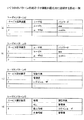
図15はいくつかのパターンの対応づけ情報を模式的に説明する図の一例である。
[Association information]
FIG. 15 is an example of a diagram for schematically explaining association information of several patterns.
パターン1.どの装置でも共通したユーザID及びパスワードで認証する場合
パターン1では、フロー定義情報には共通の1組のユーザID及びパスワードが記述されていればよい。この場合、フロー定義情報のユーザ情報は固定なので対応づけDB38は使用されない。ユーザID及びパスワードは、ユーザがワークフロー実行要求装置200に入力したものでよい。または、管理者用のユーザID及びパスワードでもよい。
パターン2.装置によってユーザID及びパスワードが異なる場合
この場合、各装置の対応づけDB38には、図15(a)に示すように各サービス提供装置300が認証に使用するユーザID及びパスワードが記憶されているものとする。ジョブ実行部31は、カレントポイントの処理を行うマシンIDからサービス提供装置300を特定して、ユーザID及びパスワードを読み出す。そして、フロー定義情報のユーザ情報を更新する。
パターン3.装置によってユーザID及びパスワードが異なるが、装置によって認証が不要な場合
この場合、図15(b)に示すように、各装置の対応づけDB38には、パターン2とほぼ同様の情報が登録されている。認証が不要な装置のユーザ名、パスワードには"−"が設定されており、ジョブ実行部31は、カレントポイントの処理を行うサービス提供装置300が認証不要な装置の場合、フロー定義画情報のユーザ名、パスワードに"−"を記述する。
パターン4.装置によって認証情報の対象が異なる場合(例えば、装置によって管理者の情報を用いる装置とログインユーザの情報を用いる場合)
この場合、図15(c)に示すように、各装置の対応づけDB38には認証対象が記憶されている。ジョブ実行部31は、カレントポイントの処理を行うサービス提供装置300の認証対象を特定し、認証対象のユーザ名とパスワードを収集し、フロー定義情報のユーザ情報を更新する。
Pattern 4. When the target of authentication information varies depending on the device (for example, when the device that uses the administrator information and the login user information are used depending on the device)
In this case, as shown in FIG. 15C, the authentication target is stored in the association DB 38 of each device. The job execution unit 31 identifies the authentication target of the
パターン5.装置の処理によって認証情報の対象が異なる場合(例えば、ストレージに保存する場合、個人領域に保存する場合と共有領域に保存する場合とで認証情報の対象が異なる場合)
この場合、図15(d)に示すように、対応づけDB38には各装置の処理毎に認証対象が記憶されている。ジョブ実行部31は、対応づけDB38からカレントポイントの処理を行うサービス提供装置300とカレントポイントのplugin IDに対応づけられた認証情報の対象を特定する。そして、認証対象のユーザ名とパスワードを収集し、フロー定義情報のユーザ情報を更新する。
In this case, as shown in FIG. 15D, the association DB 38 stores an authentication target for each process of each device. The job execution unit 31 identifies the
〔ユーザ情報の更新例〕
図16は、更新の前後のフロー定義情報におけるユーザ情報の一例を示す図である。図16(a)が更新前、図16(b)が更新後である。例えば、配信サーバ100が「userName="A" Password="aaa"」でユーザを認証し、処理を実行した。配信サーバ100のジョブ実行部31は、対応づけDB38を参照して、カレントポイントの処理を行うサービス提供装置300のユーザ情報を読み出す。そして、フロー定義情報のユーザ情報を< userName="AA" Password="aaabbb" />に更新する。これにより、次のサービス提供装置300で認証が成立し、ワークフローの実行を継続できる。
[User information update example]
FIG. 16 is a diagram illustrating an example of user information in the flow definition information before and after the update. FIG. 16A shows before update, and FIG. 16B shows after update. For example, the
〔動作手順〕
図17は、配信サーバ100又はサービス提供装置が処理を実行する際の手順を示すフローチャート図の一例である。図17は図9と同様であるが、ステップS20又はS30の後にS310、S320の処理が追加されている。
[Operation procedure]
FIG. 17 is an example of a flowchart illustrating a procedure when the
まず、ステップS30においてカレントポイントの処理行うのが自機の場合(S30のYes)、ユーザ認証部37はフロー定義情報のユーザ情報を読み出し、認証情報DB39のユーザ情報と整合性があるか否かにより認証が成立するか否かを判定する(S320)。認証が成立した場合にのみ、自機に割り当てられた処理を実行する。なお、認証が成立しない場合、実行結果としてエラーを配信サーバ100に送信する(S80)。
First, when the current point is processed in step S30 (S30: Yes), the
また、自機が実行対象機器でない場合(S20のNo)、又は、カレントポイントの処理行うのが自機でない場合(S30のNo)、ジョブ実行部31はフロー定義情報のユーザ情報を更新する(S310)。ジョブ実行部31は、カレントポイントの処理を行うサービス提供装置300を特定し、該装置におけるユーザの認証情報を読み出す。そして、フロー定義情報のユーザ情報を更新する。
When the own device is not the execution target device (No in S20), or when the current point is not processed by the own device (No in S30), the job execution unit 31 updates the user information of the flow definition information (No. S310). The job execution unit 31 identifies the
その後、ジョブ転送部32はフロー定義情報とジョブデータを転送する(S100)。以降の処理は実施例1と同様である。
Thereafter, the
本実施例の処理実行システム500によれば、ワークフローを実行する各装置でユーザを認証するので、セキュリティを維持したままワークフローを実行できる。
According to the
21 プラグイン
22 フロー制御部
23 ジョブ制御部
24 配信機能部
31 ジョブ実行部
32 ジョブ転送部
33 ジョブ受信部
34 ジョブ検知部
35 ジョブキュー
36 マシンID
100 配信サーバ
200 ワークフロー実行要求装置
300 サービス提供装置
500 処理実行システム
21 plug-in 22
DESCRIPTION OF
Claims (10)
前記第1の機器は、各処理の処理内容と次に実行すべき次処理が定義された処理定義情報及び処理対象データ若しくは処理対象データの指示情報を前記第2の機器に送信する第1の送信手段を有し、
前記第2の機器は、前記処理定義情報及び前記処理対象データ若しくは処理対象データの指示情報を受信する受信手段と、
前記処理定義情報を解析して前記次処理を自機で実行するか否かを判定する処理実行制御手段と、
前記処理実行制御手段が自機で実行すると判定した場合、前記次処理を前記処理対象データに対し実行する処理実行手段と、
前記実行順に従って、前記次処理の次に処理することが定義された処理を新たな前記次処理に変更することで前記処理定義情報を更新する定義情報更新手段と、
自機以外の前記第2の機器に前記処理定義情報及び前記処理対象データを送信する第2の送信手段と、
を有することを特徴とする処理実行システム。 A processing execution system in which a first device that receives a plurality of processes and setting of the execution order of the processes and one or more second devices that execute the processes are connected via a network,
The first device transmits processing definition information defining processing contents of each processing and next processing to be executed next, and processing target data or processing target data instruction information to the second device. Having a transmission means,
The second device includes a receiving unit that receives the processing definition information and the processing target data or instruction information of the processing target data;
A process execution control means for analyzing the process definition information and determining whether to execute the next process on its own machine;
When it is determined that the process execution control means executes on its own machine, the process execution means for executing the next process on the processing target data;
Definition information updating means for updating the process definition information by changing a process defined to be processed next to the next process to a new next process according to the execution order;
Second transmission means for transmitting the processing definition information and the processing target data to the second device other than the own device;
A processing execution system comprising:
前記処理実行制御手段は、前記次処理を実行する前記第2の機器の前記識別情報が自機の前記識別情報と一致するか否か、及び、前記次処理と自機の前記識別情報が対応づけられた処理とが一致するか否か、に基づき前記次処理を自機で実行するか否かを判定する、
ことを特徴とする請求項1記載の処理実行システム。 The process definition information is associated with identification information of the second device that executes the process for each process,
The process execution control means determines whether or not the identification information of the second device that executes the next process matches the identification information of the own apparatus, and corresponds to the identification information of the own apparatus and the next process. Determining whether or not to execute the next process on its own based on whether or not the assigned process matches.
The processing execution system according to claim 1.
前記処理実行制御手段は、再度、前記次処理を自機で実行するか否かを判定し、自機で実行すると判定した場合、前記処理実行手段が前記次処理を前記処理対象データに対し実行し、
自機で実行しないと判定した場合、前記第2の送信手段が自機以外の前記第2の機器に前記処理定義情報及び前記処理対象データを送信する、
ことを特徴とする請求項1又は2記載の処理実行システム。 After the process execution means executes the next process on the processing target data, and the definition information update means updates the process definition information,
The process execution control means determines again whether or not to execute the next process on its own machine. If it is determined to execute on the own machine, the process execution means executes the next process on the processing target data. And
If it is determined not to be executed by the own device, the second transmission unit transmits the processing definition information and the processing target data to the second device other than the own device.
The processing execution system according to claim 1 or 2, characterized in that
前記次処理を実行する他の第2の機器がファイアウォールよりも外側に存在すると判断した場合、前記他の第2の機器による前記次処理の実行を監視する監視処理が前記次処理として定義された第2の処理定義情報を作成し、
前記第2の送信手段は前記次処理を実行する前記他の第2の機器に前記処理定義情報と前記処理対象データを送信し、
自機である前記第2の機器の前記処理実行制御手段は、前記第2の処理定義情報の前記次処理を自機で実行するか否かを判定し、
前記処理実行制御手段が自機で実行すると判定した場合、前記処理実行手段は前記次処理として前記監視処理を実行する、
ことを特徴とする請求項2記載の処理実行システム。 The process execution control means includes
When it is determined that another second device that executes the next process exists outside the firewall, a monitoring process that monitors execution of the next process by the other second device is defined as the next process. Create second process definition information,
The second transmission means transmits the process definition information and the process target data to the other second device that executes the next process,
The process execution control means of the second device that is the own device determines whether or not to execute the next processing of the second process definition information on the own device,
When it is determined that the process execution control unit executes on its own machine, the process execution unit executes the monitoring process as the next process.
The processing execution system according to claim 2, wherein:
自機である前記第2の機器の前記処理実行制御手段は、前記次処理を自機で実行するか否かを判定し、自機で実行すると判定した場合、前記処理実行手段が前記次処理を前記処理対象データに対し実行し、
自機で実行しないと判定した場合、前記第2の送信手段は自機以外の第2の機器に前記処理定義情報及び前記処理対象データを送信する、
ことを特徴とする請求項4記載の処理実行システム。 The second device that is its own device executes the monitoring process and receives the processing definition information and the processing target data in which the next processing is updated from the other second device,
The process execution control means of the second device, which is the own apparatus, determines whether or not the next process is to be executed by the own apparatus. Is executed on the processing target data,
If it is determined not to be executed by the own device, the second transmission means transmits the processing definition information and the processing target data to a second device other than the own device.
The processing execution system according to claim 4, wherein:
前記第2の機器は、ユーザ情報が記憶されているユーザ情報記憶手段から読み出したユーザ情報と、前記処理定義情報に記述されたユーザ情報とが一致するか否かに基づきユーザ認証が成立したか否かを判定する認証手段を有し、
認証が成立した場合、前記処理実行手段が、前記次処理を前記処理対象データに対し実行し、
前記定義情報更新手段が前記処理定義情報を更新すると共に、前記処理実行制御手段は、前記処理定義情報のユーザ情報を、前記次処理を実行する前記第2の機器の前記認証手段が認証に使用するユーザ情報に更新する、
ことを特徴とする請求項1〜5いずれか1項記載の処理実行システム。 In the process definition information, user information of a user who operates the first device is described.
Whether the second device has achieved user authentication based on whether or not the user information read from the user information storage means storing the user information matches the user information described in the process definition information An authentication means for determining whether or not
When authentication is established, the process execution means executes the next process on the process target data,
The definition information update means updates the process definition information, and the process execution control means uses the user information of the process definition information for authentication by the authentication means of the second device that executes the next process. Update to user information
The processing execution system according to claim 1, wherein:
各第2の機器に対応づけて前記認証手段が認証に使用するユーザ情報が登録された装置別ユーザ情報を有し、
前記処理実行制御手段は、前記装置別ユーザ情報において前記次処理を実行する前記第2の機器に対応づけられたユーザ情報により、前記処理定義情報のユーザ情報を更新する、
ことを特徴とする請求項6記載の処理実行システム。 The second device is:
User-specific user information in which user information used for authentication by the authentication means is registered in association with each second device,
The process execution control means updates the user information of the process definition information with user information associated with the second device that executes the next process in the device-specific user information.
The processing execution system according to claim 6.
各第2の機器に対応づけて前記認証手段が認証に使用するユーザ情報の種類が登録された装置別ユーザ情報を有し、
前記処理実行制御手段は、前記装置別ユーザ情報において前記次処理を実行する前記第2の機器に対応づけられたユーザ情報の種類を読み出し、該ユーザ情報の種類のユーザ情報を収集して、前記処理定義情報のユーザ情報を更新する、
ことを特徴とする請求項6記載の処理実行システム。 The second device is:
A device-specific user information in which a type of user information used for authentication by the authentication unit is registered in association with each second device;
The process execution control means reads the type of user information associated with the second device that executes the next process in the device-specific user information, collects user information of the type of user information, Update user information of process definition information,
The processing execution system according to claim 6.
各処理の処理内容と次に実行すべき次処理が定義された処理定義情報及び処理対象データ若しくは処理対象データの指示情報を受信する受信手段と、
前記処理定義情報を解析して前記次処理を自機で実行するか否かを判定する処理実行制御手段と、
前記処理実行制御手段が自機で実行すると判定した場合、前記次処理を前記処理対象データに対し実行する処理実行手段と、
前記実行順に従って、前記次処理の次に処理することが定義された処理を新たな前記次処理に変更して前記処理定義情報を更新する定義情報更新手段と、
自機以外の装置に前記処理定義情報及び前記処理対象データを送信する送信手段と、
を有することを特徴とする情報処理装置。 An information processing apparatus capable of communicating via a network with a device that accepts a plurality of processes and processing execution order settings,
Receiving means for receiving processing definition information and processing definition information in which processing to be executed next and processing target data or processing target data instruction information are defined;
A process execution control means for analyzing the process definition information and determining whether to execute the next process on its own machine;
When it is determined that the process execution control means executes on its own machine, the process execution means for executing the next process on the processing target data;
Definition information updating means for updating the process definition information by changing a process defined to be processed next to the next process to the new next process according to the execution order;
Transmitting means for transmitting the processing definition information and the processing target data to a device other than the own device;
An information processing apparatus comprising:
各処理の処理内容と次に実行すべき次処理が定義された処理定義情報及び処理対象データ若しくは処理対象データの指示情報を受信する受信ステップと、
前記処理定義情報を解析して前記次処理を自機で実行するか否かを判定する処理実行制御ステップと、
前記処理実行制御手段が自機で実行すると判定した場合、前記次処理を前記処理対象データに対し実行する処理実行ステップと、
前記実行順に従って、前記次処理の次に処理することが定義された処理を新たな前記次処理に変更して前記処理定義情報を更新する定義情報更新ステップと、
自機以外の装置に前記処理定義情報及び前記処理対象データを送信する送信ステップと、を実行させるプログラム。 To an information processing apparatus capable of communicating via a network with a device that accepts multiple processes and the setting of the execution order of the processes,
A receiving step for receiving process definition information defining the next process to be executed and process definition information and process target data or process target data instruction information;
A process execution control step of analyzing the process definition information and determining whether to execute the next process on its own machine;
When it is determined that the process execution control means executes on its own machine, a process execution step of executing the next process on the processing target data;
A definition information update step for updating the process definition information by changing the process defined to be processed next to the next process to the new next process according to the execution order;
A program for executing a transmission step of transmitting the process definition information and the process target data to an apparatus other than the own apparatus.
Priority Applications (2)
| Application Number | Priority Date | Filing Date | Title |
|---|---|---|---|
| JP2013001157A JP6102264B2 (en) | 2013-01-08 | 2013-01-08 | Processing execution system, information processing apparatus, program |
| US14/104,010 US20140195585A1 (en) | 2013-01-08 | 2013-12-12 | Process executing system, process executing method, and information processing device |
Applications Claiming Priority (1)
| Application Number | Priority Date | Filing Date | Title |
|---|---|---|---|
| JP2013001157A JP6102264B2 (en) | 2013-01-08 | 2013-01-08 | Processing execution system, information processing apparatus, program |
Publications (2)
| Publication Number | Publication Date |
|---|---|
| JP2014134873A true JP2014134873A (en) | 2014-07-24 |
| JP6102264B2 JP6102264B2 (en) | 2017-03-29 |
Family
ID=51061831
Family Applications (1)
| Application Number | Title | Priority Date | Filing Date |
|---|---|---|---|
| JP2013001157A Active JP6102264B2 (en) | 2013-01-08 | 2013-01-08 | Processing execution system, information processing apparatus, program |
Country Status (2)
| Country | Link |
|---|---|
| US (1) | US20140195585A1 (en) |
| JP (1) | JP6102264B2 (en) |
Cited By (1)
| Publication number | Priority date | Publication date | Assignee | Title |
|---|---|---|---|---|
| US9176776B2 (en) | 2013-09-17 | 2015-11-03 | Ricoh Company, Ltd. | Apparatus, method, and computer-readable recording medium for processing data |
Families Citing this family (8)
| Publication number | Priority date | Publication date | Assignee | Title |
|---|---|---|---|---|
| JP6157181B2 (en) * | 2013-04-02 | 2017-07-05 | キヤノン株式会社 | Server system, control method thereof, and program thereof |
| US9277066B2 (en) * | 2013-06-28 | 2016-03-01 | Canon Kabushiki Kaisha | Communication system, communication terminal, control method, and storage medium storing program |
| KR20160076371A (en) | 2014-12-22 | 2016-06-30 | 삼성전자주식회사 | Method for processing workflow and mobile device for performing the same |
| WO2016105044A1 (en) | 2014-12-22 | 2016-06-30 | Samsung Electronics Co., Ltd. | Method of establishing connection between mobile device and image forming apparatus, and image forming apparatus and mobile device for performing the method |
| US10110767B2 (en) | 2014-12-22 | 2018-10-23 | S-Printing Solution Co., Ltd. | Method of generating workform by using BYOD service and mobile device for performing the method |
| CN105467969A (en) * | 2016-01-18 | 2016-04-06 | 京东方科技集团股份有限公司 | Manufacturing execution system |
| JP6953703B2 (en) * | 2016-10-19 | 2021-10-27 | 株式会社リコー | System, information processing method, information processing device, program |
| JP6834402B2 (en) * | 2016-11-24 | 2021-02-24 | 株式会社リコー | Information processing equipment, information processing systems, information processing methods, and programs |
Citations (3)
| Publication number | Priority date | Publication date | Assignee | Title |
|---|---|---|---|---|
| JPH09325928A (en) * | 1996-06-06 | 1997-12-16 | Fuji Xerox Co Ltd | Method and equipment for communicating message |
| JP2004289501A (en) * | 2003-03-24 | 2004-10-14 | Fuji Xerox Co Ltd | Image processing apparatus, image processing method, and program |
| US20060092834A1 (en) * | 2004-11-02 | 2006-05-04 | Fujitsu Limited | Application flow control apparatus |
Family Cites Families (5)
| Publication number | Priority date | Publication date | Assignee | Title |
|---|---|---|---|---|
| JP2000293447A (en) * | 1999-04-08 | 2000-10-20 | Hitachi Ltd | Virtual work flow managing method |
| GB2377777A (en) * | 2001-07-18 | 2003-01-22 | Hewlett Packard Co | Computer apparatus for implementing a workflow |
| US20030117650A1 (en) * | 2001-12-25 | 2003-06-26 | Masanori Wakai | Information processing device for assigning instruction information to processing subject information and method thereof |
| JP2006048122A (en) * | 2004-07-30 | 2006-02-16 | Ntt Docomo Inc | Communication system |
| JP4925969B2 (en) * | 2006-09-15 | 2012-05-09 | 株式会社リコー | Information processing apparatus, processing control method, and program |
-
2013
- 2013-01-08 JP JP2013001157A patent/JP6102264B2/en active Active
- 2013-12-12 US US14/104,010 patent/US20140195585A1/en not_active Abandoned
Patent Citations (4)
| Publication number | Priority date | Publication date | Assignee | Title |
|---|---|---|---|---|
| JPH09325928A (en) * | 1996-06-06 | 1997-12-16 | Fuji Xerox Co Ltd | Method and equipment for communicating message |
| JP2004289501A (en) * | 2003-03-24 | 2004-10-14 | Fuji Xerox Co Ltd | Image processing apparatus, image processing method, and program |
| US20060092834A1 (en) * | 2004-11-02 | 2006-05-04 | Fujitsu Limited | Application flow control apparatus |
| JP2006133894A (en) * | 2004-11-02 | 2006-05-25 | Fujitsu Ltd | Application flow controller |
Cited By (1)
| Publication number | Priority date | Publication date | Assignee | Title |
|---|---|---|---|---|
| US9176776B2 (en) | 2013-09-17 | 2015-11-03 | Ricoh Company, Ltd. | Apparatus, method, and computer-readable recording medium for processing data |
Also Published As
| Publication number | Publication date |
|---|---|
| US20140195585A1 (en) | 2014-07-10 |
| JP6102264B2 (en) | 2017-03-29 |
Similar Documents
| Publication | Publication Date | Title |
|---|---|---|
| JP6102264B2 (en) | Processing execution system, information processing apparatus, program | |
| JP6123394B2 (en) | Definition information creation system, information processing device | |
| US20150249724A1 (en) | Information processing apparatus, information processing system, and recording medium | |
| US8477347B2 (en) | Method and system for managing user setup information | |
| US8416441B2 (en) | Scan data workflow processing | |
| US10474402B2 (en) | Printing system, print management server, communication relay device, and recording medium | |
| US11722454B2 (en) | Communication apparatus, method of controlling communication apparatus, and storage medium | |
| JP6171346B2 (en) | Information processing apparatus, process execution method, and program | |
| US10922033B2 (en) | Information processing apparatus transmitting requests and communication apparatus receiving the requests | |
| JP2016015580A (en) | Cooperative processing system and cooperative processing method | |
| JP6405831B2 (en) | Information processing apparatus, communication system, and program | |
| JP2006252321A (en) | Electronic document management system, print setting device, print history device, image forming apparatus, print setting service device, temporary document keeping service device and control program | |
| JP6135215B2 (en) | Image forming apparatus, network system, method and program | |
| US20220038586A1 (en) | Image processing apparatus, control method, and medium | |
| US9571677B2 (en) | Image processing apparatus and non-transitory computer readable medium | |
| JP4631729B2 (en) | Image forming apparatus and file transmission system | |
| JP6508246B2 (en) | Processing execution system | |
| CN109639921B (en) | Communication apparatus, control method thereof, and storage medium | |
| JP4715312B2 (en) | Image forming apparatus, image forming system, file management program, and recording medium recording the program | |
| JP2020086766A (en) | Image formation device and log information acquisition system | |
| JP7263083B2 (en) | IMAGE PROCESSING DEVICE, CONTROL METHOD AND PROGRAM OF IMAGE PROCESSING DEVICE | |
| JP5315939B2 (en) | Image forming apparatus, information processing system, information processing method, and program | |
| US20220377200A1 (en) | Image processing system, control method for the image processing system, and storage medium | |
| JP6418031B2 (en) | Image processing device | |
| JP2019009825A (en) | Image processing device |
Legal Events
| Date | Code | Title | Description |
|---|---|---|---|
| A621 | Written request for application examination |
Free format text: JAPANESE INTERMEDIATE CODE: A621 Effective date: 20151210 |
|
| A977 | Report on retrieval |
Free format text: JAPANESE INTERMEDIATE CODE: A971007 Effective date: 20161031 |
|
| A131 | Notification of reasons for refusal |
Free format text: JAPANESE INTERMEDIATE CODE: A131 Effective date: 20161115 |
|
| A521 | Written amendment |
Free format text: JAPANESE INTERMEDIATE CODE: A523 Effective date: 20170113 |
|
| TRDD | Decision of grant or rejection written | ||
| A01 | Written decision to grant a patent or to grant a registration (utility model) |
Free format text: JAPANESE INTERMEDIATE CODE: A01 Effective date: 20170131 |
|
| A61 | First payment of annual fees (during grant procedure) |
Free format text: JAPANESE INTERMEDIATE CODE: A61 Effective date: 20170213 |
|
| R151 | Written notification of patent or utility model registration |
Ref document number: 6102264 Country of ref document: JP Free format text: JAPANESE INTERMEDIATE CODE: R151 |