JP2014128052A - Control device for vehicle - Google Patents
Control device for vehicle Download PDFInfo
- Publication number
- JP2014128052A JP2014128052A JP2012280921A JP2012280921A JP2014128052A JP 2014128052 A JP2014128052 A JP 2014128052A JP 2012280921 A JP2012280921 A JP 2012280921A JP 2012280921 A JP2012280921 A JP 2012280921A JP 2014128052 A JP2014128052 A JP 2014128052A
- Authority
- JP
- Japan
- Prior art keywords
- control
- inverter
- voltage
- current
- control mode
- Prior art date
- Legal status (The legal status is an assumption and is not a legal conclusion. Google has not performed a legal analysis and makes no representation as to the accuracy of the status listed.)
- Pending
Links
Images


Classifications
-
- H—ELECTRICITY
- H02—GENERATION; CONVERSION OR DISTRIBUTION OF ELECTRIC POWER
- H02P—CONTROL OR REGULATION OF ELECTRIC MOTORS, ELECTRIC GENERATORS OR DYNAMO-ELECTRIC CONVERTERS; CONTROLLING TRANSFORMERS, REACTORS OR CHOKE COILS
- H02P27/00—Arrangements or methods for the control of AC motors characterised by the kind of supply voltage
- H02P27/04—Arrangements or methods for the control of AC motors characterised by the kind of supply voltage using variable-frequency supply voltage, e.g. inverter or converter supply voltage
- H02P27/06—Arrangements or methods for the control of AC motors characterised by the kind of supply voltage using variable-frequency supply voltage, e.g. inverter or converter supply voltage using dc to ac converters or inverters
- H02P27/08—Arrangements or methods for the control of AC motors characterised by the kind of supply voltage using variable-frequency supply voltage, e.g. inverter or converter supply voltage using dc to ac converters or inverters with pulse width modulation
- H02P27/085—Arrangements or methods for the control of AC motors characterised by the kind of supply voltage using variable-frequency supply voltage, e.g. inverter or converter supply voltage using dc to ac converters or inverters with pulse width modulation wherein the PWM mode is adapted on the running conditions of the motor, e.g. the switching frequency
-
- H—ELECTRICITY
- H02—GENERATION; CONVERSION OR DISTRIBUTION OF ELECTRIC POWER
- H02P—CONTROL OR REGULATION OF ELECTRIC MOTORS, ELECTRIC GENERATORS OR DYNAMO-ELECTRIC CONVERTERS; CONTROLLING TRANSFORMERS, REACTORS OR CHOKE COILS
- H02P2209/00—Indexing scheme relating to controlling arrangements characterised by the waveform of the supplied voltage or current
- H02P2209/11—Sinusoidal waveform
-
- H—ELECTRICITY
- H02—GENERATION; CONVERSION OR DISTRIBUTION OF ELECTRIC POWER
- H02P—CONTROL OR REGULATION OF ELECTRIC MOTORS, ELECTRIC GENERATORS OR DYNAMO-ELECTRIC CONVERTERS; CONTROLLING TRANSFORMERS, REACTORS OR CHOKE COILS
- H02P2209/00—Indexing scheme relating to controlling arrangements characterised by the waveform of the supplied voltage or current
- H02P2209/13—Different type of waveforms depending on the mode of operation
Landscapes
- Engineering & Computer Science (AREA)
- Power Engineering (AREA)
- Control Of Ac Motors In General (AREA)
- Electric Propulsion And Braking For Vehicles (AREA)
- Control Of Motors That Do Not Use Commutators (AREA)
Abstract
Description
本発明は、車両の制御装置に関し、特に、コンバータおよびインバータを介して供給された電力によって駆動するモータを搭載した車両において、コンバータの出力電圧を制御する技術に関する。 The present invention relates to a vehicle control device, and more particularly to a technique for controlling an output voltage of a converter in a vehicle equipped with a motor driven by electric power supplied via a converter and an inverter.
電動モータを駆動源として搭載したハイブリッド車、燃料電池車、電気自動車が知られている。電動モータには、たとえば3相交流モータが用いられる。そのような電動モータには、インバータから交流電力が供給される。 Hybrid vehicles, fuel cell vehicles, and electric vehicles equipped with an electric motor as a drive source are known. For example, a three-phase AC motor is used as the electric motor. AC power is supplied from such an inverter to such an electric motor.
インバータの制御には、種々の技術が用いられ得る。インバータの制御に用いられる技術の一例として、特開2006−311768号公報(特許文献1)は、正弦波PWM(Pulse Width Modulation)制御方式、過変調PWM制御方式、矩形波制御方式の中から選択された制御方式を用いてインバータを制御することを開示する。特開2006−311768号公報においては、一例として、第66段落に記載されているように、インバータの変調度に基づいて制御方式が選択される。 Various techniques can be used to control the inverter. As an example of a technique used for controlling an inverter, Japanese Patent Laid-Open No. 2006-31768 (Patent Document 1) is selected from a sine wave PWM (Pulse Width Modulation) control method, an overmodulation PWM control method, and a rectangular wave control method. It is disclosed that the inverter is controlled by using the controlled method. In Japanese Patent Laid-Open No. 2006-31768, as an example, as described in paragraph 66, a control method is selected based on the modulation degree of the inverter.
インバータの変調度に応じて制御方式を選択すると、たとえば電動モータの回転速度あるいはトルクが外乱の影響によって急変し、その結果電動モータの駆動電圧の振幅が急変すると、インバータの変調率も急変し、インバータの制御方式が変更され得る。この場合、所望される制御方式とは異なる制御方式でインバータが制御されるため、制御方式を速やかに元に戻すことが望ましい。 When the control method is selected according to the modulation degree of the inverter, for example, the rotation speed or torque of the electric motor changes suddenly due to the influence of disturbance, and as a result, when the amplitude of the drive voltage of the electric motor changes suddenly, the modulation rate of the inverter also changes suddenly. The control method of the inverter can be changed. In this case, since the inverter is controlled by a control method different from the desired control method, it is desirable to quickly restore the control method.
また、PWM制御方式ではインバータのスイッチング動作に伴う損失があることから、矩形波制御方式が選択できる条件下では、制御方式を速やかに矩形波制御方式に移行させることが望ましい。 In addition, since there is a loss associated with the switching operation of the inverter in the PWM control method, it is desirable to quickly shift the control method to the rectangular wave control method under conditions where the rectangular wave control method can be selected.
本発明は、上述の課題に鑑みてなされたものであって、その目的は、インバータの制御方式を変更することである。 The present invention has been made in view of the above-described problems, and an object thereof is to change an inverter control method.
車両には、電圧を変換して出力するコンバータと、コンバータから出力された直流電力を交流電力に変換するインバータと、インバータから供給される交流電力により駆動するモータとが搭載される。この車両の制御装置は、インバータの変調度に応じて選択される制御モードでインバータを制御するためのインバータ制御手段と、目標の制御モードを選択するための選択手段と、目標の制御モードと現在の制御モードとが異なると、制御モードが目標の制御モードに切換えるまでインバータの変調度が変化するようにコンバータの出力電圧を変化させるためのコンバータ制御手段とを備える。 The vehicle is mounted with a converter that converts and outputs a voltage, an inverter that converts DC power output from the converter into AC power, and a motor that is driven by AC power supplied from the inverter. The vehicle control device includes an inverter control means for controlling the inverter in a control mode selected in accordance with a modulation degree of the inverter, a selection means for selecting a target control mode, a target control mode, and a current control mode. When the control mode is different from the control mode, converter control means is provided for changing the output voltage of the converter so that the modulation degree of the inverter changes until the control mode is switched to the target control mode.
この構成によれば、目標の制御モードと現在の制御モードとが異なれば、コンバータの出力電圧の変化に伴ってインバータの変調度が変化することにより、制御モードが切換えられる。したがって、インバータの制御方式を所望のものに変更することができる。 According to this configuration, if the target control mode is different from the current control mode, the control mode is switched by changing the modulation degree of the inverter in accordance with the change in the output voltage of the converter. Therefore, the inverter control method can be changed to a desired one.
インバータの変調度が所定のしきい値を超えると制御モードを切換えるようにしてもよい。この場合、目標の制御モードと現在の制御モードとが異なると、しきい値よりも大きい値を目標変調度として設定し、インバータの変調度が目標変調度まで変化するようにコンバータの出力電圧を低下させてもよい。 The control mode may be switched when the modulation degree of the inverter exceeds a predetermined threshold value. In this case, if the target control mode is different from the current control mode, a value greater than the threshold value is set as the target modulation factor, and the converter output voltage is set so that the inverter modulation factor changes to the target modulation factor. It may be lowered.
逆に、インバータの変調度が所定のしきい値を下回ると制御モードを切換えるようにしてもよい。この場合、目標の制御モードと現在の制御モードとが異なると、しきい値よりも小さい値を目標変調度として設定し、インバータの変調度が目標変調度まで変化するようにコンバータの出力電圧を増大させてもよい。 Conversely, the control mode may be switched when the modulation degree of the inverter falls below a predetermined threshold value. In this case, if the target control mode is different from the current control mode, a value smaller than the threshold value is set as the target modulation degree, and the output voltage of the converter is set so that the inverter modulation degree changes to the target modulation degree. It may be increased.
インバータの出力電圧と入力電圧との比から算出することができる変調度を用いることで、インバータの状態を数値として具体的に把握しながらコンバータを制御できる。 By using the modulation degree that can be calculated from the ratio between the output voltage and the input voltage of the inverter, the converter can be controlled while specifically grasping the state of the inverter as a numerical value.
目標の制御モードを、運転者のアクセル操作に応じて選択するようにしてもよい。これにより、運転者が希望する制御モードを実現することができる。 The target control mode may be selected according to the driver's accelerator operation. Thereby, the control mode desired by the driver can be realized.
以下に、本発明の実施の形態について図面を参照して詳細に説明する。なお、以下では図中の同一または相当部分には同一符号を付して、その説明は原則として繰返さないものとする。 Embodiments of the present invention will be described below in detail with reference to the drawings. In the following, the same or corresponding parts in the drawings are denoted by the same reference numerals, and the description thereof will not be repeated in principle.
図1は、車両に駆動源として搭載された交流電動モータの制御システム100の全体構成図である。制御システム100は、直流電圧発生部10♯と、平滑コンデンサC0と、インバータ14と、交流電動モータM1と、制御装置30とを備える。
FIG. 1 is an overall configuration diagram of a
交流電動モータM1は、たとえば、電動車両(ハイブリッド自動車、電気自動車や燃料電池車等の電気エネルギによって車両駆動力を発生可能な自動車を包括的に表現するものとする)の駆動輪にトルクを発生させるように構成された走行用電動モータである。あるいは、この交流電動モータM1は、エンジンによって駆動される発電機の機能を持つように構成されてもよく、電動モータおよび発電機の機能を併せ持つように構成されてもよい。すなわち、本実施の形態において、交流電動モータは、モータジェネレータを含むものである。さらに、交流電動モータM1は、たとえば、エンジン始動を行ない得るようなものとしてハイブリッド自動車に組み込まれるようにしてもよい。 AC electric motor M1 generates torque on the drive wheels of, for example, an electric vehicle (a vehicle that can generate vehicle driving force by electric energy such as a hybrid vehicle, an electric vehicle, and a fuel cell vehicle). It is the electric motor for driving | running | working comprised so that it might make it. Alternatively, AC electric motor M1 may be configured to have a function of a generator driven by an engine, or may be configured to have both functions of an electric motor and a generator. That is, in the present embodiment, the AC electric motor includes a motor generator. Furthermore, AC electric motor M1 may be incorporated in a hybrid vehicle, for example, so that the engine can be started.
直流電圧発生部10♯は、直流電源Bと、システムリレーSR1,SR2と、平滑コンデンサC1と、昇圧コンバータ12とを含む。
DC
直流電源Bは、代表的には、ニッケル水素またはリチウムイオン等の二次電池や電気二重層キャパシタ等の再充電可能な蓄電装置により構成される。直流電源Bが出力する直流電圧Vbおよび入出力される直流電流Ibは、電圧センサ10および電流センサ11によってそれぞれ検知される。
The DC power supply B is typically constituted by a rechargeable power storage device such as a secondary battery such as nickel metal hydride or lithium ion or an electric double layer capacitor. The DC voltage Vb output from the DC power supply B and the input / output DC current Ib are detected by the
システムリレーSR1は、直流電源Bの正極端子および電力線6の間に接続され、システムリレーSR1は、直流電源Bの負極端子および電力線5の間に接続される。システムリレーSR1,SR2は、制御装置30からの信号SEによりオン/オフされる。
System relay SR 1 is connected between the positive terminal of DC power supply B and power line 6, and system relay SR 1 is connected between the negative terminal of DC power supply B and
昇圧コンバータ12は、リアクトルL1と、電力用半導体スイッチング素子Q1,Q2と、ダイオードD1,D2とを含む。電力用半導体スイッチング素子Q1およびQ2は、電力線7および電力線5の間に直列に接続される。電力用半導体スイッチング素子Q1およびQ2のオンオフは、制御装置30からのスイッチング制御信号S1およびS2によって制御される。
この発明の実施の形態において、電力用半導体スイッチング素子(以下、単に「スイッチング素子」と称する)としては、IGBT(Insulated Gate Bipolar Transistor)、電力用MOS(Metal Oxide Semiconductor)トランジスタあるいは、電力用バイポーラトランジスタ等を用いることができる。スイッチング素子Q1,Q2に対しては、逆並列ダイオードD1,D2が配置されている。リアクトルL1は、スイッチング素子Q1およびQ2の接続ノードと電力線6の間に接続される。また、平滑コンデンサC0は、電力線7および電力線5の間に接続される。
In the embodiment of the present invention, an IGBT (Insulated Gate Bipolar Transistor), a power MOS (Metal Oxide Semiconductor) transistor, or a power bipolar transistor is used as a power semiconductor switching element (hereinafter simply referred to as “switching element”). Etc. can be used. Anti-parallel diodes D1, D2 are arranged for switching elements Q1, Q2. Reactor L1 is connected between a connection node of switching elements Q1 and Q2 and power line 6. Further, the smoothing capacitor C0 is connected between the power line 7 and the
平滑コンデンサC0は、電力線7の直流電圧を平滑化する。電圧センサ13は、平滑コンデンサC0の両端の電圧、すなわち、電力線7上の直流電圧VHを検出する。以下では、インバータ14の直流リンク電圧に相当する直流電圧VHを「システム電圧VH」とも称する。一方、電力線6の直流電圧VLは、電圧センサ19によって検出される。電圧センサ13,19によって検出された直流電圧VH,VLは、制御装置30へ入力される。
The smoothing capacitor C0 smoothes the DC voltage of the power line 7. The
インバータ14は、電力線7および電力線5の間に並列に設けられる、U相上下アーム15と、V相上下アーム16と、W相上下アーム17とから成る。各相上下アームは、電力線7および電力線5の間に直列接続されたスイッチング素子から構成される。たとえば、U相上下アーム15は、スイッチング素子Q3,Q4から成り、V相上下アーム16は、スイッチング素子Q5,Q6から成り、W相上下アーム17は、スイッチング素子Q7,Q8から成る。また、スイッチング素子Q3〜Q8に対して、逆並列ダイオードD3〜D8がそれぞれ接続されている。スイッチング素子Q3〜Q8のオンオフは、制御装置30からのスイッチング制御信号S3〜S8によって制御される。
代表的には、交流電動モータM1は、3相の永久磁石型同期電動モータであり、U,V,W相の3つのコイルの一端が中性点に共通接続されて構成される。さらに、各相コイルの他端は、各相上下アーム15〜17のスイッチング素子の中間点と接続されている。
Typically, AC electric motor M1 is a three-phase permanent magnet type synchronous electric motor, and is configured such that one end of three U, V, and W phase coils is commonly connected to a neutral point. Furthermore, the other end of each phase coil is connected to the midpoint of the switching elements of the upper and
昇圧コンバータ12は、基本的には、PWM制御に用いられる搬送波の1周期に相当するスイッチング周期の各々において、スイッチング素子Q1およびQ2が相補的かつ交互にオンオフするように制御される。昇圧コンバータ12は、スイッチング素子Q1,Q2のオン期間比(デューティ比)を制御することによって、昇圧比(VH/VL)を制御することができる。したがって、直流電圧VL,VHの検出値と電圧指令値VH♯とに従って演算されたデューティ比に従って、スイッチング素子Q1,Q2のオンオフが制御される。
スイッチング素子Q1をスイッチング素子Q2と相補的にオンオフすることにより、リアクトルL1の電流方向に応じて制御を切換えることなく直流電源Bの充電および放電の両方に対応することができる。すなわち、電圧指令値VH♯に従うシステム電圧VHの制御を通じて、昇圧コンバータ12は、回生および力行の両方に対応することができる。
By switching on and off the switching element Q1 in a complementary manner with the switching element Q2, it is possible to cope with both charging and discharging of the DC power source B without switching control according to the current direction of the reactor L1. That is, through control of system voltage VH according to voltage command value VH #, boost
なお、交流電動モータM1の低出力時には、昇圧コンバータ12による昇圧を行なうことなく、VH=VL(昇圧比=1.0)の状態で交流電動モータM1を制御することができる。この場合(以下、「非昇圧モードとも称する」)には、スイッチング素子Q1およびQ2が、オンおよびオフにそれぞれ固定されるので、昇圧コンバータ12での電力損失が低下する。
When AC electric motor M1 is at a low output, AC electric motor M1 can be controlled in a state of VH = VL (step-up ratio = 1.0) without boosting by
インバータ14は、交流電動モータM1のトルク指令値が正(Tqcom>0)の場合には、平滑コンデンサC0から直流電圧が供給されると制御装置30からのスイッチング制御信号S3〜S8に応答した、スイッチング素子Q3〜Q8のスイッチング動作により直流電圧を交流電圧に変換して正のトルクを出力するように交流電動モータM1を駆動する。また、インバータ14は、交流電動モータM1のトルク指令値が零の場合(Tqcom=0)には、スイッチング制御信号S3〜S8に応答したスイッチング動作により、直流電圧を交流電圧に変換してトルクが零になるように交流電動モータM1を駆動する。これにより、交流電動モータM1は、トルク指令値Tqcomによって指定された零または正のトルクを発生するように駆動される。
When the torque command value of AC electric motor M1 is positive (Tqcom> 0),
さらに、制御システム100が搭載された電動車両の回生制動時には、交流電動モータM1のトルク指令値Tqcomは負に設定される(Tqcom<0)。この場合には、インバータ14は、スイッチング制御信号S3〜S8に応答したスイッチング動作により、交流電動モータM1が発電した交流電圧を直流電圧に変換し、その変換した直流電圧(システム電圧VH)を平滑コンデンサC0を介して昇圧コンバータ12へ供給する。
Further, during regenerative braking of an electric vehicle equipped with
なお、ここで言う回生制動とは、電動車両を運転するドライバーによるフットブレーキ操作があった場合の回生発電を伴う制動や、フットブレーキを操作しないものの、走行中にアクセルペダルをオフすることで回生発電をさせながら車両を減速(または加速の中止)させることを含む。 The regenerative braking here refers to braking with regenerative power generation when the driver operating the electric vehicle performs a footbrake operation, or regenerative braking by turning off the accelerator pedal while driving, although the footbrake is not operated. This includes decelerating (or stopping acceleration) the vehicle while generating electricity.
電流センサ24は、交流電動モータM1に流れる電流(相電流)を検出し、その検出値を制御装置30へ出力する。なお、三相電流iu,iv,iwの瞬時値の和は零であるので、図1に示すように2相分のモータ電流(たとえば、V相電流ivおよびW相電流iw)を検出するように配置してもよい。
回転角センサ(レゾルバ)25は、交流電動モータM1のロータ回転角θを検出し、その検出した回転角θを制御装置30へ送出する。制御装置30では、回転角θに基づき交流電動モータM1の回転速度Nmtおよび回転角速度ωを算出できる。なお、回転角センサ25については、回転角θを制御装置30にてモータ電圧や電流から直接演算することによって、配置を省略してもよい。
The rotation angle sensor (resolver) 25 detects the rotor rotation angle θ of the AC
制御装置30は、電子制御ユニット(ECU)により構成され、予め記憶されたプログラムを図示しないCPU(Central Processing Unit)で実行することによるソフトウェア処理および/または専用の電子回路によるハードウェア処理により、制御システム100の動作を制御する。
The
代表的な機能として、制御装置30は、入力されたトルク指令値Tqcom、電圧センサ10によって検出された直流電圧Vb、電流センサ11によって検出された直流電流Ib、電圧センサ13によって検出されたシステム電圧VHおよび電流センサ24によって検出されるモータ電流iv,iw、回転角センサ25からの回転角θ等に基づいて、後述する制御方式により交流電動モータM1がトルク指令値Tqcomに従ったトルクを出力するように、昇圧コンバータ12およびインバータ14の動作を制御する。
As a representative function, the
すなわち、制御装置30は、直流電圧VHを電圧指令値VH♯に従って上記のように制御するために昇圧コンバータ12のスイッチング制御信号S1,S2を生成する。また、制御装置30は、交流電動モータM1の出力トルクをトルク指令値Tqcomに従って制御するための制御信号S3〜S8を生成する。制御信号S1〜S8は、昇圧コンバータ12およびインバータ14へ入力される。
That is,
トルク指令値Tqcomは、アクセル開度および車速などをパラメータに有するマップに従って算出される。 Torque command value Tqcom is calculated according to a map having accelerator opening, vehicle speed, and the like as parameters.
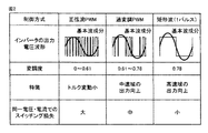
図2は、交流電動モータ制御のためのインバータ制御方式を説明する図である。図2に示すように、本発明の実施の形態に従う交流電動モータの制御システムでは、インバータ14による交流電動モータ制御について3つの制御方式を切換えて使用する。
FIG. 2 is a diagram illustrating an inverter control system for controlling an AC electric motor. As shown in FIG. 2, the AC electric motor control system according to the embodiment of the present invention switches between three control methods for AC electric motor control by
正弦波PWM制御は、一般的なPWM制御として用いられるものであり、各相アームにおけるスイッチング素子のオンオフを、正弦波状の電圧指令値と搬送波(代表的には、三角波)との電圧比較に従って制御する。この結果、上アーム素子のオン期間に対応するハイレベル期間と、下アーム素子のオン期間に対応するローレベル期間との集合について、一定期間内でその基本波成分が正弦波となるようにデューティ比が制御される。 The sine wave PWM control is used as a general PWM control, and controls on / off of the switching element in each phase arm according to a voltage comparison between a sine wave voltage command value and a carrier wave (typically, a triangular wave). To do. As a result, for a set of a high level period corresponding to the on period of the upper arm element and a low level period corresponding to the on period of the lower arm element, the duty is set so that the fundamental wave component becomes a sine wave within a certain period. The ratio is controlled.
以下、本明細書では、インバータによる直流交流電圧変換における、システム電圧VHに対する交流電動モータM1への印加電圧(線間電圧の実効値)の比を「変調度」を定義する。正弦波PWM制御の適用は、基本的には、各相の交流電圧振幅(相電圧)がシステム電圧VHと等しくなる状態が限界である。すなわち、正弦波PWM制御では、変調度を0.61倍までしか高めることができない。 Hereinafter, in this specification, the ratio of the applied voltage (effective value of the line voltage) to the AC electric motor M1 with respect to the system voltage VH in the DC / AC voltage conversion by the inverter is defined as “degree of modulation”. The application of the sine wave PWM control is basically limited to a state where the AC voltage amplitude (phase voltage) of each phase becomes equal to the system voltage VH. That is, in the sine wave PWM control, the modulation degree can be increased only up to 0.61 times.
一方、矩形波電圧制御では、電動モータの電気角360度に相当する期間内で、ハイレベル期間およびローレベル期間の比が1:1の矩形波1パルス分をインバータが出力する。これにより、変調度は0.78まで高められる。 On the other hand, in the rectangular wave voltage control, the inverter outputs one pulse of the rectangular wave whose ratio between the high level period and the low level period is 1: 1 within the period corresponding to the electrical angle of 360 degrees of the electric motor. Thereby, the modulation degree is increased to 0.78.
過変調PWM制御は、搬送波の振幅よりも大きい振幅の電圧指令値(正弦波状)について、その振幅を拡大した上で、上記正弦波PWM制御と同様のPWM制御を行なうものである。この結果、基本波成分を歪ませることによって、変調度を0.61〜0.78の範囲まで高めることができる。 In the overmodulation PWM control, the voltage command value (sine wave shape) having an amplitude larger than the amplitude of the carrier wave is enlarged, and the same PWM control as the sine wave PWM control is performed. As a result, the modulation factor can be increased to a range of 0.61 to 0.78 by distorting the fundamental wave component.
本実施の形態に従う交流電動モータM1の制御システム100では、交流電動モータM1の状態に応じて、上述の正弦波PWM制御、過変調PWM制御および矩形波電圧制御が選択的に適用される。
In
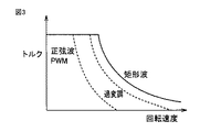
概略的には、図3に示すように、低速回転領域から中速回転領域にかけては正弦波PWMの制御が選択され、中速回転領域から高速回転領域にかけては過変調制御が選択され、より高速回転領域では矩形波電圧制御が選択される。制御方式の具体的な選択方法については後述する。 Schematically, as shown in FIG. 3, sine wave PWM control is selected from the low-speed rotation region to the medium-speed rotation region, and overmodulation control is selected from the medium-speed rotation region to the high-speed rotation region. In the rotation region, rectangular wave voltage control is selected. A specific method for selecting the control method will be described later.
図4に示すように、正弦波PWM制御および過変調PWM制御では、交流電動モータM1の電流位相φiが、最適電流進角ライン42上となるようにインバータ14によるモータ電流制御が行なわれる。図4の横軸はd軸電流Idを示しており、図4の縦軸はq軸電流Iqを示している。
As shown in FIG. 4, in the sine wave PWM control and overmodulation PWM control, the motor current control by the
最適電流進角ライン42は、Id−Iq平面上の等トルク線上における交流電動モータM1での損失が参照となる電流位相点の集合として描かれる。よって、アクセル開度および車速などをパラメータとして有するマップに従って決定された、交流電動モータM1に対するトルク指令値Tqcomに対応する等トルク線と、最適電流進角ライン42との交点に対応するd軸およびq軸の電流指令値Idcom,Iqcomが生成される。最適電流進角ラインは、予め実験ないしシミュレーションによって求めることができる。したがって、各トルク指令値に対応させて最適電流進角ライン42上の電流指令値Idcom,Iqcomの組み合わせを決定するマップを予め作成して、制御装置30内に記憶させておくことができる。
The optimum
図4では、零点位置を起点とするId,Iqの組み合わせによる電流ベクトルの先端位置(電流位相)が、出力トルクの増加に応じて変化する軌跡を矢印で示している。出力トルクが増加するのに応じて、電流の大きさ(Id−Iq平面上での電流ベクトルの大きさに相当)が増加する。上述したように、正弦波PWM制御および過変調PWM制御では、電流指令値Idcom,Iqcomの設定により、電流位相が最適電流進角ライン42上に制御される。
In FIG. 4, the trajectory in which the tip position (current phase) of the current vector resulting from the combination of Id and Iq starting from the zero point position changes as the output torque increases is indicated by an arrow. As the output torque increases, the current magnitude (corresponding to the magnitude of the current vector on the Id-Iq plane) increases. As described above, in the sine wave PWM control and overmodulation PWM control, the current phase is controlled on the optimum
矩形波電圧制御では、インバータ14によって交流電動モータM1の電流位相を直接制御することはできない。矩形波電圧制御では弱め界磁制御を行なうため、電圧位相φvを大きくすることにより出力トルクが増大される。これに伴い、界磁電流であるd軸電流Idの絶対値が増加する。この結果、電流ベクトルの先端位置(電流位相)が、最適電流進角ライン42から図中左側(進角側)に離れる。電流ベクトルは最適電流進角ライン42上にないため、矩形波電圧制御においては、交流電動モータM1の損失が増大する。
In the rectangular wave voltage control, the
逆に、矩形波電圧制御時に電流位相φiが所定のφth(基準値)よりも小さくなると、矩形波電圧制御からPWM制御への遷移が指示される。 Conversely, when the current phase φi becomes smaller than a predetermined φth (reference value) during rectangular wave voltage control, a transition from rectangular wave voltage control to PWM control is instructed.
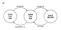
図5を参照して、正弦波PWM制御、過変調PWM制御および矩形波電圧制御の間のモード切換を説明する。正弦波PWMまたは過変調PWM制御の適用時には、後述するd軸およびq軸の電圧指令値Vd♯,Vq♯、ならびにシステム電圧VHから、下記の式1を用いて変調度Kmdが算出される。
With reference to FIG. 5, mode switching between sinusoidal PWM control, overmodulation PWM control, and rectangular wave voltage control will be described. When sine wave PWM or overmodulation PWM control is applied, modulation degree Kmd is calculated using the
Kmd=(Vd♯2+Vq♯2)1/2/VH ・・・(1)
正弦波PWM制御が実行されているときに、インバータ14の変調度が0.61を超えると制御モードが正弦波PWM制御から過変調PWM制御に切換えられる。過変調PWM制御が実行されているときに、インバータ14の変調度が0.61よりも小さい所定のしきい値SH(SH=0.61−α)を下回ると、制御モードが過変調PWM制御から正弦波PWM制御に切換えられる。
Kmd = (Vd # 2 + Vq # 2 ) 1/2 / VH (1)
When the modulation degree of the
過変調PWM制御が実行されているときに、インバータ14の変調度がさらに増大し、0.78を超えると、制御モードが過変調PWM制御から矩形波電圧制御に切換えられる。
When overmodulation PWM control is being executed, the modulation degree of the
一方、矩形波電圧制御中、出力トルクの低下に応じて電流位相φiが基準値φthよりも小さくなると、過変調PWM制御モードへの遷移が指示される。 On the other hand, during the rectangular wave voltage control, when the current phase φi becomes smaller than the reference value φth as the output torque decreases, a transition to the overmodulation PWM control mode is instructed.
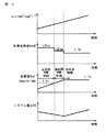
正弦波PWM制御、過変調PWM制御および矩形波電圧制御におけるエネルギ損失は、図6(a)に示すように、システム電圧VHに応じて変化し得る。図6(a)〜(c)は、交流電動モータM1の出力(回転速度とトルクとの積)を一定とし、システム電圧VHのみを変化させた条件下での制御システムの挙動を示す。 The energy loss in the sine wave PWM control, overmodulation PWM control, and rectangular wave voltage control can change according to the system voltage VH as shown in FIG. FIGS. 6A to 6C show the behavior of the control system under the condition that the output (product of the rotational speed and torque) of the AC electric motor M1 is constant and only the system voltage VH is changed.
図6(a)には、3つの制御モードを通じたシステム電圧VHと制御システムの全体損失の関係が示される。図6(b)には、システム電圧VHと変調度Kmdとの関係が示される。図6(c)には、システム電圧VHとモータ電流位相との関係が示されている。 FIG. 6A shows the relationship between the system voltage VH and the total loss of the control system through the three control modes. FIG. 6B shows the relationship between the system voltage VH and the modulation degree Kmd. FIG. 6C shows the relationship between the system voltage VH and the motor current phase.
図6(a)〜(c)を参照して、正弦波PWM制御および過変調PWM制御が適用される領域では、システム電圧VHを低下して変調度を上昇させる程、損失が減少する。そして、矩形波電圧制御が適用される動作点44において、昇圧コンバータ12およびインバータ14の損失が最小となるため、システム全体の損失も最小となる。
With reference to FIGS. 6A to 6C, in a region where the sine wave PWM control and the overmodulation PWM control are applied, the loss decreases as the system voltage VH is decreased and the modulation degree is increased. At the
矩形波電圧制御が適用される領域では、変調度は0.78に固定されるため、システム電圧VHを低下させる程、同一出力を得るための電圧位相φvが大きくなる。これに付随して、前述したように、弱め界磁電流の増加によって、電流位相が最適電流進角ライン42から遠ざかるため、交流電動モータM1での損失増加によってシステム損失が増加する。すなわち、矩形波電圧制御では、システム電圧VHが低下するほどシステムの全体損失が増加することになる。
In the region where the rectangular wave voltage control is applied, the degree of modulation is fixed at 0.78, so that the voltage phase φv for obtaining the same output increases as the system voltage VH decreases. Accompanying this, as described above, the current phase moves away from the optimum
逆に、システム電圧VHを高くすることによりPWM制御を適用すると、交流電動モータM1電流位相は、最適電流進角ライン42に沿って制御できる。しかしながら、PWM制御で交流電動モータM1を動作させると、交流電動モータM1の損失は低減できる一方で、スイッチング回数の増加によってインバータ14の損失が増加することになる。
Conversely, when PWM control is applied by increasing the system voltage VH, the AC electric motor M1 current phase can be controlled along the optimum
したがって、交流電動モータM1を含む制御システム全体の損失が最小となるのは、矩形波電圧制御が適用され、かつ、交流電動モータM1の電流位相が最適電流進角ライン42の近傍にあるときである。すなわち、システム電圧VHは、このような状態となるように設定することが好ましい。
Therefore, the loss of the entire control system including the AC electric motor M1 is minimized when the rectangular wave voltage control is applied and the current phase of the AC electric motor M1 is in the vicinity of the optimum
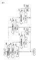
図7を参照して、正弦波PWM制御および過変調PWM制御における具体的な処理について説明する。図7は、本発明の実施の形態に従う交流電動モータの制御システムにおけるPWM制御での制御構成を説明する機能ブロック図である。図7を含めて、以下で説明されるブロック図に記載されたモータ制御のための各機能ブロックは、制御装置30による、ハードウェア的あるいはソフトウェア的な処理によって実現される。
With reference to FIG. 7, a specific process in the sine wave PWM control and the overmodulation PWM control will be described. FIG. 7 is a functional block diagram illustrating a control configuration in PWM control in the control system for an AC electric motor according to the embodiment of the present invention. Each functional block for motor control described in the block diagrams described below including FIG. 7 is realized by hardware or software processing by the
図7を参照して、PWM制御部200は、電流指令生成部210と、変換部220と、電流フィードバック部230とを含む。
Referring to FIG. 7,
電流指令生成部210は、予め作成されたマップ等に従って、交流電動モータM1のトルク指令値Tqcomに応じた、d軸電流指令値Idcomおよびq軸電流指令値Iqcomを生成する。
Current
変換部220は、交流電動モータM1に流れる3相モータ電流iu,iv,iwをロータ回転角θを用いた座標変換によって、d軸およびq軸の2相電流id,iqに変換して出力する。具体的には、電流センサ24によって検出されるV相電流ivおよびW相電流iwからU相電流iu(iu=−iv−iw)が算出される。これらの電流iu,iv,iwに基づき、回転角センサ25によって検出される回転角θに応じて、実際のd軸電流idおよびq軸電流iqが算出される。
The
電流フィードバック部230には、d軸電流指令値Idcomと算出された実際のd軸電流idとの差ΔId(ΔId=Idcom−Id)、ならびにq軸電流指令値Iqcomと算出された実際のq軸電流iqとの差ΔIq(ΔIq=Iqcom−Iq)が入力される。電流フィードバック部230は、d軸電流差ΔIdおよびq軸電流差ΔIqのそれぞれについて、所定ゲインによるPI(比例積分)演算を行なって制御偏差を求め、この制御偏差に応じたd軸電圧指令値Vd♯およびq軸電圧指令値Vq♯を生成する。さらに、電流フィードバック部230は、交流電動モータM1の回転角θを用いた座標変換(2相→3相)によって、d軸電圧指令値Vd♯およびq軸電圧指令値Vq♯をU相、V相、W相の各相電圧指令Vu,Vv,Vwに変換するとともに、各相電圧指令値Vu,Vv,Vwに従ってスイッチング制御信号S3〜S8を発生する。インバータ14がスイッチング制御信号S3〜S8に従ったスイッチング動作により、交流電動モータM1の各相に疑似正弦波電圧が生成される。
The
本発明の実施の形態に従うモータ駆動システムの制御装置30は、さらに、目標変調度算出部310、必要電圧算出部320、変調度フィードバック部330、電圧フィードバック部360を備える。
目標変調度算出部310、必要電圧算出部320および変調度フィードバック部330は、インバータ14の変調度Kmdを目標変調度Kmd#に維持するための昇圧コンバータ12の出力電圧としての要求電圧VHreqを算出するための機能である。
Target modulation
より具体的には、目標変調度算出部310が、アクセル開度に応じて選択される目標の制御モード(以下では要求制御モードとも記載する)と、現在の制御モードCntModeとの組合わせ毎に目標変調度Kmd#を設定する。目標変調度Kmd#の設定方法については後で詳細に説明する。 More specifically, for each combination of the target control mode selected according to the accelerator opening (hereinafter also referred to as the required control mode) and the current control mode CntMode, the target modulation degree calculation unit 310 A target modulation degree Kmd # is set. A method for setting the target modulation degree Kmd # will be described in detail later.
必要電圧算出部320は、目標トルク(トルク指令値Tqcom)を実現するために必要な昇圧コンバータ12の出力電圧としての必要電圧tVHを、目標トルク(トルク指令値Tqcom)から算出する。一例として、必要電圧算出部320は、目標変調度算出部310によって算出された目標変調度Kmd#と、目標トルク(トルク指令値Tqcom)と、交流電動モータM1の回転速度Nmtとをパラメータとして有するマップに従って、必要電圧tVHを算出する。より詳細には、一例として、トルク指令値Tqcomと回転速度Nmtとからマップを参照して求められる電圧Vrを目標変調度Kmd#で除算することにより、必要電圧tVHが算出される。電圧Vrは、交流電動モータM1への印加電圧(線間電圧の実効値)である。
Necessary
変調度フィードバック部330は、目標変調度Kmd#に対する実変調度Kmdに比(Kmd/Kmd#)を求め、この比に現在のシステム電圧VHを乗算することによって、目標システム電圧を求める。さらにこの目標システム電圧から現在のシステム電圧VHを減算した値ΔVHとその積分値∫ΔVHが求められる。これらに比例ゲインKpおよび積分ゲインKiがそれぞれ乗算されて、比例項KpΔVHおよび積分項Ki∫ΔVHが求められる。変調度フィードバック部330は、これらの比例項KpΔVHおよび積分項Ki∫ΔVHの和を補正電圧VHhoseiとして算出する。
The modulation
必要電圧tVHと補正電圧VHhoseiとの和が電圧指令値VH#として電圧フィードバック部360に入力される。電圧フィードバック部360は、電圧指令値VH#と現在のシステム電圧VHとに基づき、昇圧コンバータ12の出力電圧が電圧指令値VH#となるように、スイッチング制御信号S1,S2を生成する。
The sum of required voltage tVH and correction voltage VHhosei is input to
図8,9を参照して、要求制御モードならびに目標変調度Kmd#を設定するために目標変調度算出部310において実行される処理について説明する。図8を参照して、ステップ(以下、ステップをSと略す)100にて、現在の要求制御モードが正弦波PWM制御であるか否かが判断される。現在の制御モードが正弦波PWM制御でなく(S100にてNO)、かつ、アクセル開度Accrが所定のしきい値tAccr1よりも大きいと(S102にてYES)、S104にて、要求制御モードが正弦波PWM制御とされる。なお、アクセル開度Accrは周知の通りアクセル開度センサを用いて検出される。
With reference to FIGS. 8 and 9, processing executed in the target modulation
現在の制御モードが正弦波PWM制御であり(S100にてYES)、かつ、アクセル開度Accrが所定のしきい値tAccr2(tAccr2<tAccr1)よりも小さいと(S106にてYES)、S108にて、要求制御モードが正弦波PWM制御ではなくなる。 If the current control mode is sinusoidal PWM control (YES at S100) and accelerator opening degree Accr is smaller than predetermined threshold value tAccr2 (tAccr2 <tAccr1) (YES at S106), at S108 The required control mode is not sine wave PWM control.
図9を参照して、現在の要求制御モードが正弦波PWM制御であり(S200にてYES)、かつ現在の制御モードが正弦波PWM制御であると(S202にてYES)、S203にて、0〜0.61の範囲内で開発者により予め定められた所定値L1Sinが目標変調度Kmd#に設定される。 Referring to FIG. 9, when the current required control mode is sine wave PWM control (YES in S200) and the current control mode is sine wave PWM control (YES in S202), in S203, A predetermined value L1Sin predetermined by the developer within the range of 0 to 0.61 is set as the target modulation degree Kmd #.
現在の要求制御モードが正弦波PWM制御であり(S200にてYES)、かつ現在の制御モードが過変調PWM制御であると(S202にてNO,S204にてYES)、S205にて、制御モードが過変調PWM制御から正弦波PWM制御に切換えるときのしきい値SH(SH=0.61−α)よりも小さくなるように開発者により予め定められた所定値L1Ovmが目標変調度Kmd#に設定される。上述したように、インバータ14の変調度Kmdが目標変調度Kmd#に一致するようにコンバータ12の出力電圧が制御されるため、結果として、制御モードが過変調PWM制御から正弦波PWM制御に切換わるまでコンバータ12の出力電圧が増大される。
If the current required control mode is sine wave PWM control (YES in S200) and the current control mode is overmodulation PWM control (NO in S202, YES in S204), the control mode is determined in S205. Is set to a target modulation degree Kmd # by a predetermined value L1Ovm determined in advance by the developer so that becomes smaller than a threshold value SH (SH = 0.61−α) when switching from overmodulation PWM control to sine wave PWM control. Is set. As described above, the output voltage of the
現在の要求制御モードが正弦波PWM制御であり(S200にてYES)、かつ現在の制御モードが矩形波電圧制御であると(S202にてNO,S204にてNO)、S206にて、開発者により予め定められた所定値L1VpHが目標変調度Kmd#に設定される。 If the current required control mode is sine wave PWM control (YES at S200) and the current control mode is rectangular wave voltage control (NO at S202, NO at S204), the developer at S206 The predetermined value L1VpH determined in advance is set as the target modulation degree Kmd #.
現在の要求制御モードが正弦波PWM制御ではなく(S200にてNO)、かつ現在の制御モードが正弦波PWM制御であると(S212にてYES)、S213にて、0.78よりも大きい所定値L2Sinが目標変調度Kmd#に設定される。 If the current required control mode is not sine wave PWM control (NO in S200) and the current control mode is sine wave PWM control (YES in S212), a predetermined value larger than 0.78 is set in S213. The value L2Sin is set to the target modulation degree Kmd #.
現在の要求制御モードが正弦波PWM制御ではなく(S200にてNO)、かつ現在の制御モードが過変調PWM制御であると(S212にてNO,S214にてYES)、S215にて、0.78よりも大きい所定値L2Ovmが目標変調度Kmd#に設定される。所定値L2Ovmは、所定値L2Sinよりも大きくてもよく、小さくてもよく、同じであってもよい。 If the current required control mode is not sine wave PWM control (NO in S200) and the current control mode is overmodulation PWM control (NO in S212, YES in S214), 0. A predetermined value L2Ovm greater than 78 is set as the target modulation degree Kmd #. The predetermined value L2Ovm may be larger than the predetermined value L2Sin, may be smaller, or may be the same.
上述したように、インバータ14の実変調度Kmdが0.78以上になると制御モードがPWM制御から矩形波制御に切換えられるため、0.78よりも大きい所定値L2Ovmが目標変調度Kmd#に設定されることによって、図10に示すように、制御モードがPWM制御から矩形波制御に切換えられるまでコンバータ12の出力電圧が速やかに低下される。
As described above, when the actual modulation degree Kmd of the
現在の要求制御モードが正弦波PWM制御ではなく(S200にてNO)、かつ現在の制御モードが矩形波電圧制御であると(S212にてNO,S214にてNO)、S216にて、開発者により予め定められた所定値L2VpHが目標変調度Kmd#に設定される。 If the current required control mode is not sine wave PWM control (NO in S200) and the current control mode is rectangular wave voltage control (NO in S212, NO in S214), the developer is determined in S216. The predetermined value L2VpH determined in advance is set as the target modulation degree Kmd #.
以下、図11を参照して、矩形波制御方式時における制御ブロック図を説明する。なお、上述のように矩形波制御方式時には、変調度が固定されるため、PWM制御において含まれるような変調度のフィードバック制御は構成されない。 Hereinafter, a control block diagram in the rectangular wave control method will be described with reference to FIG. Note that, as described above, in the rectangular wave control method, the modulation degree is fixed, and thus the feedback control of the modulation degree as included in the PWM control is not configured.
図11を参照して、矩形波制御ブロック400は、変換部410と、トルク推定部420と、トルクフィードバック部430とを含む。
Referring to FIG. 11, rectangular
変換部410は、交流電動モータM1に流れる3相モータ電流iu,iv,iwをロータ回転角θを用いた座標変換によって、d軸およびq軸の2相電流id,iqに変換して出力する。具体的には、電流センサ24によって検出されるV相電流ivおよびW相電流iwからU相電流iu(iu=−iv−iw)が算出される。これらの電流iu,iv,iwに基づき、回転角センサ25によって検出される回転角θに応じて、d軸電流idおよびq軸電流iqが生成される。
The
トルク推定部420は、予め計測したトルクと電流との関係を定めたマップに従い、d軸電流idおよびq軸電流iqから交流電動モータM1の実際のトルクTqを推定する。
トルクフィードバック部430へは、トルク指令値Tqcomに対するトルク偏差ΔTq(ΔTq=Tqcom−Tq)が入力される。トルクフィードバック部430は、トルク偏差ΔTqについて所定ゲインによるPI演算を行なって制御偏差を求め、求められた制御偏差に応じて矩形波電圧の位相φvを設定する。具体的には、正トルク発生(Tqcom>0)時には、トルク不足時には電圧位相を進める一方で、トルク過剰時には電圧位相を遅らせるとともに、負トルク発生(Tqcom<0)時には、トルク不足時には電圧位相を遅らせる一方で、トルク過剰時には電圧位相を進める。
さらに、トルクフィードバック部430は、設定された電圧位相φvに従って、各相電圧指令値(矩形波パルス)Vu,Vv,Vwを発生するとともに、各相電圧指令値Vu,Vv,Vwに従ってスイッチング制御信号S3〜S8を発生する。インバータ14がスイッチング制御信号S3〜S8に従ったスイッチング動作を行なうことにより、電圧位相φvに従った矩形波パルスが、モータの各相電圧として印加される。
Further,
このように、矩形波制御方式時には、トルク(電力)のフィードバック制御により、モータトルク制御を行なうことができる。 Thus, in the rectangular wave control method, the motor torque control can be performed by the feedback control of the torque (electric power).
本発明の実施の形態に従うモータ駆動システムの制御装置30では、さらに、必要電圧算出部510および電流位相フィードバック部520を備える。
必要電圧算出部510は、目標トルク(トルク指令値Tqcom)を実現するために必要な昇圧コンバータ12の出力電圧としての必要電圧tVHを、目標トルク(トルク指令値Tqcom)から算出する。一例として、必要電圧算出部510は、所定の目標変調度Kmd#と、目標トルク(トルク指令値Tqcom)と、交流電動モータM1の回転速度Nmtとをパラメータとして有するマップに従って、必要電圧tVHを算出する。より詳細には、一例として、トルク指令値Tqcomと回転速度Nmtとからマップを参照して求められる電圧Vrを目標変調度Kmd#で除算することにより、必要電圧tVHが算出される。電圧Vrは、交流電動モータM1への印加電圧(線間電圧の実効値)である。
Necessary
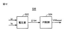
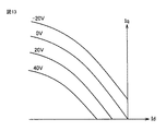
電流位相フィードバック部520は、変換部410によって生成されたd軸電流idおよびq軸電流iqに応じて、システム電圧VHの補正値VHhoseiを算出する。電流位相フィードバック部520は、図12に示すように、電圧差算出部522と、PI制御部524とを含む。電圧差算出部522は、図13に示すように、d軸電流idとq軸電流iqとをパラメータとして有するマップに従って、電圧差ΔVHを算出する。
The current
図12に戻って、PI制御部524は、電圧差ΔVHとその積分値∫ΔVHに、比例ゲインKpおよび積分ゲインKiをそれぞれ乗算されて、比例項KpΔVHおよび積分項Ki∫ΔVHを算出する。PI制御部524は、これらの比例項KpΔVHおよび積分項Ki∫ΔVHの和を補正電圧VHhoseiとして算出する。
Returning to FIG. 12, the
図11に戻って、必要電圧tVHと補正電圧VHhoseiとの和が電圧指令値VH#として電圧フィードバック部550に入力される。電圧フィードバック部550は、電圧指令値VH#と、現在のシステム電圧VHに基づき、昇圧コンバータ12の出力電圧が電圧指令値VHcomとなるように、スイッチング制御信号S1,S2を生成する。
Returning to FIG. 11, the sum of necessary voltage tVH and correction voltage VHhosei is input to
今回開示された実施の形態は、すべての点で例示であって制限的なものではないと考えられるべきである。本発明の範囲は上記した説明ではなくて特許請求の範囲によって示され、特許請求の範囲と均等の意味および範囲内でのすべての変更が含まれることが意図される。 The embodiment disclosed this time should be considered as illustrative in all points and not restrictive. The scope of the present invention is defined by the terms of the claims, rather than the description above, and is intended to include any modifications within the scope and meaning equivalent to the terms of the claims.
12 昇圧コンバータ、14 インバータ、30 制御装置、100 制御システム、200 PWM制御部、210 電流指令生成部、220,410 変換部、230 電流フィードバック部、310 目標変調度算出部、320,510 必要電圧算出部、330 変調度フィードバック部、360,550 電圧フィードバック部、400 矩形波制御ブロック、420 トルク推定部、430 トルクフィードバック部、450 信号発生部、520 電流位相フィードバック部、522 電圧差算出部、524 PI制御部、M1 交流電動モータ。 12 boost converter, 14 inverter, 30 control device, 100 control system, 200 PWM control unit, 210 current command generation unit, 220, 410 conversion unit, 230 current feedback unit, 310 target modulation degree calculation unit, 320, 510 necessary voltage calculation Unit, 330 modulation degree feedback unit, 360, 550 voltage feedback unit, 400 rectangular wave control block, 420 torque estimation unit, 430 torque feedback unit, 450 signal generation unit, 520 current phase feedback unit, 522 voltage difference calculation unit, 524 PI Control unit, M1 AC electric motor.
Claims (4)
前記インバータの変調度に応じて選択される制御モードで前記インバータを制御するためのインバータ制御手段と、
前記インバータの目標の制御モードを選択するための選択手段と、
前記目標の制御モードと現在の制御モードとが異なると、前記制御モードが前記目標の制御モードに切換わるまで前記インバータの変調度が変化するように前記コンバータの出力電圧を変化させるためのコンバータ制御手段とを備える、車両の制御装置。 A vehicle control device equipped with a converter that converts and outputs a voltage, an inverter that converts DC power output from the converter into AC power, and a motor that is driven by AC power supplied from the inverter. And
Inverter control means for controlling the inverter in a control mode selected according to the modulation degree of the inverter;
Selection means for selecting a target control mode of the inverter;
Converter control for changing the output voltage of the converter so that the modulation degree of the inverter changes until the control mode is switched to the target control mode when the target control mode is different from the current control mode And a vehicle control device.
前記コンバータ制御手段は、
前記目標の制御モードと現在の制御モードとが異なると、前記しきい値よりも大きい値を目標変調度として設定し、
前記インバータの変調度が前記目標変調度まで変化するように前記コンバータの出力電圧を低下させるための手段とを備える、請求項1に記載の車両の制御装置。 The inverter control means switches the control mode when the modulation degree of the inverter exceeds a predetermined threshold value,
The converter control means includes
When the target control mode is different from the current control mode, a value larger than the threshold is set as the target modulation degree,
The vehicle control device according to claim 1, further comprising: means for reducing an output voltage of the converter so that a modulation degree of the inverter changes to the target modulation degree.
前記コンバータ制御手段は、
前記目標の制御モードと現在の制御モードとが異なると、前記しきい値よりも小さい値を目標変調度として設定し、
前記インバータの変調度が前記目標変調度まで変化するように前記コンバータの出力電圧を増大させる、請求項1に記載の車両の制御装置。 The inverter control means switches the control mode when the modulation degree of the inverter falls below a predetermined threshold value,
The converter control means includes
When the target control mode is different from the current control mode, a value smaller than the threshold is set as a target modulation degree,
The vehicle control device according to claim 1, wherein an output voltage of the converter is increased so that a modulation degree of the inverter changes to the target modulation degree.
Priority Applications (3)
| Application Number | Priority Date | Filing Date | Title |
|---|---|---|---|
| JP2012280921A JP2014128052A (en) | 2012-12-25 | 2012-12-25 | Control device for vehicle |
| US14/136,325 US20140176029A1 (en) | 2012-12-25 | 2013-12-20 | Vehicle and control device for vehicle |
| CN201310719397.5A CN103904982A (en) | 2012-12-25 | 2013-12-24 | Vehicle and control device for vehicle |
Applications Claiming Priority (1)
| Application Number | Priority Date | Filing Date | Title |
|---|---|---|---|
| JP2012280921A JP2014128052A (en) | 2012-12-25 | 2012-12-25 | Control device for vehicle |
Publications (2)
| Publication Number | Publication Date |
|---|---|
| JP2014128052A true JP2014128052A (en) | 2014-07-07 |
| JP2014128052A5 JP2014128052A5 (en) | 2015-11-26 |
Family
ID=50973867
Family Applications (1)
| Application Number | Title | Priority Date | Filing Date |
|---|---|---|---|
| JP2012280921A Pending JP2014128052A (en) | 2012-12-25 | 2012-12-25 | Control device for vehicle |
Country Status (3)
| Country | Link |
|---|---|
| US (1) | US20140176029A1 (en) |
| JP (1) | JP2014128052A (en) |
| CN (1) | CN103904982A (en) |
Cited By (3)
| Publication number | Priority date | Publication date | Assignee | Title |
|---|---|---|---|---|
| JP2016123168A (en) * | 2014-12-24 | 2016-07-07 | トヨタ自動車株式会社 | Drive unit |
| WO2018229874A1 (en) * | 2017-06-13 | 2018-12-20 | 三菱電機株式会社 | Motor drive device, electric air blower, electric vacuum cleaner, and hand drier |
| US11108351B2 (en) | 2019-03-05 | 2021-08-31 | Toyota Jidosha Kabushiki Kaisha | Electric motor control device |
Families Citing this family (5)
| Publication number | Priority date | Publication date | Assignee | Title |
|---|---|---|---|---|
| FR3027748B1 (en) * | 2014-10-27 | 2016-11-04 | Valeo Equip Electr Moteur | METHOD AND DEVICE FOR CONTROLLING A POLYNHASE SYNCHRONOUS ROTARY ELECTRIC MACHINE AND REVERSIBLE ELECTRIC MACHINE FOR A MOTOR VEHICLE CORRESPONDING THERETO |
| JP2017045901A (en) * | 2015-08-27 | 2017-03-02 | トヨタ自動車株式会社 | Reflux diode and on-vehicle power supply device |
| CN105048843B (en) * | 2015-09-14 | 2018-04-10 | 阳光电源股份有限公司 | A kind of PWM method of inverter, device and system |
| FR3062004B1 (en) * | 2017-01-16 | 2020-01-10 | Valeo Equipements Electriques Moteur | CONTROL SYSTEM FOR A ROTATING ELECTRIC MACHINE |
| JP7028008B2 (en) * | 2018-03-22 | 2022-03-02 | 株式会社デンソー | system |
Citations (2)
| Publication number | Priority date | Publication date | Assignee | Title |
|---|---|---|---|---|
| JP2006311768A (en) * | 2005-05-02 | 2006-11-09 | Toyota Motor Corp | Controller of motor drive system |
| JP2011160546A (en) * | 2010-01-29 | 2011-08-18 | Aisin Aw Co Ltd | Controller for motor drive devices |
Family Cites Families (6)
| Publication number | Priority date | Publication date | Assignee | Title |
|---|---|---|---|---|
| DE19608039A1 (en) * | 1996-03-02 | 1997-09-04 | Bosch Gmbh Robert | Control device for an asynchronous machine, in particular as a drive for electric vehicles |
| JP5109290B2 (en) * | 2006-05-30 | 2012-12-26 | トヨタ自動車株式会社 | Electric motor drive control system and control method thereof |
| JP4424428B2 (en) * | 2008-03-18 | 2010-03-03 | トヨタ自動車株式会社 | Electric motor drive control device, vehicle including the same, and electric motor drive control method |
| JP4497235B2 (en) * | 2008-08-08 | 2010-07-07 | トヨタ自動車株式会社 | AC motor control apparatus and control method |
| JP5297953B2 (en) * | 2009-09-08 | 2013-09-25 | トヨタ自動車株式会社 | Electric motor drive system for electric vehicle |
| JPWO2011135694A1 (en) * | 2010-04-28 | 2013-07-18 | 株式会社日立製作所 | Power converter |
-
2012
- 2012-12-25 JP JP2012280921A patent/JP2014128052A/en active Pending
-
2013
- 2013-12-20 US US14/136,325 patent/US20140176029A1/en not_active Abandoned
- 2013-12-24 CN CN201310719397.5A patent/CN103904982A/en active Pending
Patent Citations (2)
| Publication number | Priority date | Publication date | Assignee | Title |
|---|---|---|---|---|
| JP2006311768A (en) * | 2005-05-02 | 2006-11-09 | Toyota Motor Corp | Controller of motor drive system |
| JP2011160546A (en) * | 2010-01-29 | 2011-08-18 | Aisin Aw Co Ltd | Controller for motor drive devices |
Cited By (4)
| Publication number | Priority date | Publication date | Assignee | Title |
|---|---|---|---|---|
| JP2016123168A (en) * | 2014-12-24 | 2016-07-07 | トヨタ自動車株式会社 | Drive unit |
| WO2018229874A1 (en) * | 2017-06-13 | 2018-12-20 | 三菱電機株式会社 | Motor drive device, electric air blower, electric vacuum cleaner, and hand drier |
| US11108351B2 (en) | 2019-03-05 | 2021-08-31 | Toyota Jidosha Kabushiki Kaisha | Electric motor control device |
| US11757395B2 (en) | 2019-03-05 | 2023-09-12 | Denso Corporation | Electric motor control device |
Also Published As
| Publication number | Publication date |
|---|---|
| US20140176029A1 (en) | 2014-06-26 |
| CN103904982A (en) | 2014-07-02 |
Similar Documents
| Publication | Publication Date | Title |
|---|---|---|
| US8639405B2 (en) | Electric motor drive system for an electric vehicle | |
| JP4329855B2 (en) | AC motor control device and AC motor control method | |
| JP5133834B2 (en) | AC motor control device | |
| JP4729526B2 (en) | Electric motor drive control device | |
| JP4635703B2 (en) | Control device for motor drive system | |
| JP4604820B2 (en) | Control device for motor drive system | |
| US9762152B2 (en) | Motor control system for executing drive control of an alternating-current motor | |
| JP5482574B2 (en) | AC motor control system | |
| JP2014128052A (en) | Control device for vehicle | |
| JP2007159368A (en) | Control unit of motor drive system | |
| JP2010161907A (en) | Controller for motor driving control system | |
| JP2006320039A (en) | Controller of motor drive system | |
| JP5955761B2 (en) | Vehicle control device | |
| JP2013062934A (en) | Motor control system | |
| JP5281370B2 (en) | AC motor control device | |
| JP2011067010A (en) | Motor drive of vehicle | |
| JP5375679B2 (en) | Control device for motor drive system | |
| JP5958400B2 (en) | Motor drive control device | |
| JP5618948B2 (en) | Motor control system | |
| JP5352326B2 (en) | Motor drive control device | |
| JP5969382B2 (en) | AC motor control system | |
| JP5290048B2 (en) | Vehicle motor control system | |
| JP2010088240A (en) | Control system for ac motor | |
| JP2010166707A (en) | Controller of ac motor | |
| JP5884297B2 (en) | Motor drive control system, vehicle equipped with the same, and motor drive control system control method |
Legal Events
| Date | Code | Title | Description |
|---|---|---|---|
| A621 | Written request for application examination |
Free format text: JAPANESE INTERMEDIATE CODE: A621 Effective date: 20150107 |
|
| A521 | Written amendment |
Free format text: JAPANESE INTERMEDIATE CODE: A523 Effective date: 20151007 |
|
| A131 | Notification of reasons for refusal |
Free format text: JAPANESE INTERMEDIATE CODE: A131 Effective date: 20151027 |
|
| A977 | Report on retrieval |
Free format text: JAPANESE INTERMEDIATE CODE: A971007 Effective date: 20151030 |
|
| A02 | Decision of refusal |
Free format text: JAPANESE INTERMEDIATE CODE: A02 Effective date: 20160315 |