JP2014110568A - Image processing device, image processing method, and program - Google Patents
Image processing device, image processing method, and program Download PDFInfo
- Publication number
- JP2014110568A JP2014110568A JP2012264772A JP2012264772A JP2014110568A JP 2014110568 A JP2014110568 A JP 2014110568A JP 2012264772 A JP2012264772 A JP 2012264772A JP 2012264772 A JP2012264772 A JP 2012264772A JP 2014110568 A JP2014110568 A JP 2014110568A
- Authority
- JP
- Japan
- Prior art keywords
- image
- phase
- pixel
- eye
- unit
- Prior art date
- Legal status (The legal status is an assumption and is not a legal conclusion. Google has not performed a legal analysis and makes no representation as to the accuracy of the status listed.)
- Pending
Links
Images


Classifications
-
- H—ELECTRICITY
- H04—ELECTRIC COMMUNICATION TECHNIQUE
- H04N—PICTORIAL COMMUNICATION, e.g. TELEVISION
- H04N13/00—Stereoscopic video systems; Multi-view video systems; Details thereof
- H04N13/30—Image reproducers
- H04N13/302—Image reproducers for viewing without the aid of special glasses, i.e. using autostereoscopic displays
- H04N13/305—Image reproducers for viewing without the aid of special glasses, i.e. using autostereoscopic displays using lenticular lenses, e.g. arrangements of cylindrical lenses
-
- H—ELECTRICITY
- H04—ELECTRIC COMMUNICATION TECHNIQUE
- H04N—PICTORIAL COMMUNICATION, e.g. TELEVISION
- H04N13/00—Stereoscopic video systems; Multi-view video systems; Details thereof
- H04N13/30—Image reproducers
- H04N13/366—Image reproducers using viewer tracking
- H04N13/373—Image reproducers using viewer tracking for tracking forward-backward translational head movements, i.e. longitudinal movements
-
- H—ELECTRICITY
- H04—ELECTRIC COMMUNICATION TECHNIQUE
- H04N—PICTORIAL COMMUNICATION, e.g. TELEVISION
- H04N13/00—Stereoscopic video systems; Multi-view video systems; Details thereof
- H04N13/30—Image reproducers
- H04N13/366—Image reproducers using viewer tracking
- H04N13/376—Image reproducers using viewer tracking for tracking left-right translational head movements, i.e. lateral movements
Landscapes
- Engineering & Computer Science (AREA)
- Multimedia (AREA)
- Signal Processing (AREA)
- Testing, Inspecting, Measuring Of Stereoscopic Televisions And Televisions (AREA)
- Computer Graphics (AREA)
- Physics & Mathematics (AREA)
- General Physics & Mathematics (AREA)
- Theoretical Computer Science (AREA)
- Controls And Circuits For Display Device (AREA)
Abstract
Description
本技術は、画像処理装置、画像処理方法、およびプログラムに関し、特に、クロストークが目立たない高画質の3D画像を容易に表示することができるようにした画像処理装置、画像処理方法、およびプログラムに関する。 The present technology relates to an image processing device, an image processing method, and a program, and more particularly, to an image processing device, an image processing method, and a program that can easily display a high-quality 3D image with less noticeable crosstalk. .
ディスプレイ上に表示された3D画像のうちの左目用の画像を視聴者の左目に見せ、右目用の画像を視聴者の右目に見せることにより、3D用の眼鏡を装着しない視聴者に3D画像を提供する表示装置(以下、裸眼3D表示装置という)がある。裸眼3D表示装置としては、シート状のレンチキュラレンズが貼り付けられたディスプレイを備えるレンチキュラ式表示装置と、表面に遮光バリアが設けられたディスプレイを備えるバリア式表示装置がある。 The left eye image of the 3D image displayed on the display is shown to the viewer's left eye, and the right eye image is shown to the viewer's right eye, so that the 3D image is displayed to the viewer who does not wear the 3D glasses. There is a display device (hereinafter referred to as a naked-eye 3D display device). As a naked-eye 3D display device, there are a lenticular display device including a display on which a sheet-like lenticular lens is attached, and a barrier display device including a display having a light-shielding barrier on the surface.
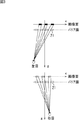
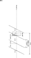
図1は、レンチキュラ式表示装置のディスプレイの構成の一例を示す図である。 FIG. 1 is a diagram illustrating an example of a configuration of a display of a lenticular display device.
図1に示すように、レンチキュラ式表示装置10では、ディスプレイ11の表面に、シート状のレンチキュラレンズ12が貼り付けられている。図1の例では、レンチキュラレンズ12は、ディスプレイ11に対して斜め方向に貼り付けられている。
As shown in FIG. 1, in the
図2は、ディスプレイ11に表示される画像の適視位置からの見え方を説明する図である。
FIG. 2 is a diagram for explaining how an image displayed on the
図2に示すように、レンチキュラ式表示装置10では、レンチキュラレンズ12により、ディスプレイ11上の視聴者の左目で見える領域と右目で見える領域が限定される。具体的には、視聴者が適視位置からディスプレイ11に表示される画像を見る場合、ディスプレイ11上の左目で見える領域と右目で見える領域は重ならず、交互に存在する。
As shown in FIG. 2, in the
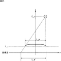
図3は、バリア式表示装置のディスプレイに表示される画像の適視位置からの見え方を説明する図である。 FIG. 3 is a diagram illustrating how the image displayed on the display of the barrier display device is seen from an appropriate viewing position.
図3に示すように、バリア式表示装置では、遮光バリア21により、視聴者の左目で見える領域と右目で見える領域が限定される。具体的には、レンチキュラ式表示装置10の場合と同様に、視聴者が適視位置からディスプレイに表示される画像を見る場合、ディスプレイ上の左目で見える領域と右目で見える領域は重ならず、交互に存在する。
As shown in FIG. 3, in the barrier display device, the area that can be seen by the viewer's left eye and the area that can be seen by the right eye are limited by the
以上のように、裸眼3D表示装置では、視聴者が適視位置からディスプレイに表示される画像を見る場合、ディスプレイ上の左目で見える領域と右目で見える領域は重ならず、交互に存在する。 As described above, in the naked-eye 3D display device, when the viewer views an image displayed on the display from an appropriate viewing position, the area seen by the left eye and the area seen by the right eye on the display do not overlap and exist alternately.
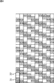
従って、図4に示すように、裸眼3D表示装置のディスプレイは、右目で見える領域と左目で見える領域に対応して右目用の画像31と左目用の画像32を交互に表示する。これにより、視聴者は、左目で左目用の画像のみを見るとともに、右目で右目用の画像のみを見ることができる。その結果、3D画像を見ることができる。なお、図4の例では、右目用の画像31は白画像であり、左目用の画像32は黒画像である。 Therefore, as shown in FIG. 4, the display of the naked-eye 3D display device alternately displays an image 31 for the right eye and an image 32 for the left eye corresponding to the region seen by the right eye and the region seen by the left eye. Accordingly, the viewer can see only the image for the left eye with the left eye and can see only the image for the right eye with the right eye. As a result, a 3D image can be seen. In the example of FIG. 4, the image 31 for the right eye is a white image, and the image 32 for the left eye is a black image.
しかしながら、視聴者が適視位置以外の位置から画像を見る場合、クロストークや逆視が発生する場合がある。 However, when the viewer views the image from a position other than the appropriate viewing position, crosstalk or reverse viewing may occur.
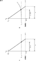
そこで、図5に示すように、視位置の変化に応じてレンチキュラレンズや遮光バリアの位置を物理的に制御する方法が考案されている(例えば、特許文献1参照)。 Therefore, as shown in FIG. 5, a method of physically controlling the positions of the lenticular lens and the light shielding barrier according to the change in the viewing position has been devised (see, for example, Patent Document 1).
具体的には、例えば、図5に示すように、視聴者が適視位置から画面に向かって左側に移動した場合、左目で見える領域と右目で見える領域は、図中x軸の正の方向に移動する。従って、このとき、裸眼3D表示装置は、遮光バリア21をx軸の負の方向に移動させることにより、左目で見える領域と右目で見える領域をx軸の負の方向に戻す。なお、本明細書では、特に断りのない限り、画面の走査方向を正方向とする軸をx軸とする。
Specifically, for example, as shown in FIG. 5, when the viewer moves from the appropriate viewing position to the left side toward the screen, the area seen by the left eye and the area seen by the right eye are in the positive direction of the x axis in the figure. Move to. Accordingly, at this time, the naked-eye 3D display device moves the
また、図6に示すように、視位置の変化に応じて左目用の画像と右目用の画像の表示位置を変更する方法が考案されている(例えば、特許文献1および特許文献2参照)。
In addition, as shown in FIG. 6, a method has been devised in which the display positions of the left-eye image and the right-eye image are changed in accordance with the change in the viewing position (see, for example,
具体的には、例えば、図6に示すように、視聴者が適視位置から画面に向かって左側に移動した場合、左目で見える領域と右目で見える領域は、図中x軸の正の方向に移動する。従って、このとき、裸眼3D表示装置は、左目用の画像と右目用の画像の表示位置をx軸の正の方向に移動させる。 Specifically, for example, as shown in FIG. 6, when the viewer moves from the appropriate viewing position to the left side toward the screen, the area seen by the left eye and the area seen by the right eye are in the positive direction of the x axis in the figure. Move to. Accordingly, at this time, the naked-eye 3D display device moves the display positions of the left-eye image and the right-eye image in the positive direction of the x axis.
例えば、図6に示すように、視聴者が適視位置に存在する場合に、3つのサブ画素からなる4つの画素71乃至74において、x軸の正の方向に順に、左目用の画像、右目用の画像、左目用の画像、右目用の画像が割り当てられているとする。この場合、視聴者が適視位置より画面に向かって左側に移動したとき、裸眼3D表示装置は、例えば1サブ画素分だけ左側に左目用の画像と右目用の画像の表示位置を移動させる。
For example, as shown in FIG. 6, when the viewer is present at the appropriate viewing position, the left-eye image and the right-eye are sequentially displayed in the positive direction of the x axis in the four
また、視聴者が適視位置より画面に向かってさらに左側に移動した場合、裸眼3D表示装置は、例えば1サブ画素分だけさらに左側に左目用の画像と右目用の画像の表示位置を移動させる。そして、さらに視聴者が適視位置より画面に向かって左側に移動した場合、さらに例えば1サブ画素分だけ左側に左目用の画像と右目用の画像の表示位置を移動させる。 Further, when the viewer moves further leftward from the appropriate viewing position toward the screen, the naked-eye 3D display device moves the display positions of the left-eye image and the right-eye image further to the left by, for example, one subpixel. . When the viewer further moves to the left side from the appropriate viewing position toward the screen, the display positions of the left-eye image and the right-eye image are moved further to the left by, for example, one subpixel.
しかしながら、視位置の変化に応じてレンチキュラレンズや遮光バリアの位置を物理的に制御する方法では、特殊な制御デバイスが必要である。 However, a special control device is required in the method of physically controlling the positions of the lenticular lens and the light shielding barrier according to the change in the viewing position.
また、視位置の変化に応じて左目用の画像と右目用の画像の表示位置を変更する方法では、クロストークが発生する場合がある。 Further, in the method of changing the display positions of the left-eye image and the right-eye image according to the change in the viewing position, crosstalk may occur.
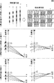
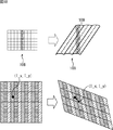
即ち、サブ画素のサイズは有限であるため、視位置によって、1つのサブ画素が左目と右目で見える場合がある。具体的には、図7Aに示すように、サブ画素の境界と、左目で見える領域と右目で見える領域の境界とが一致する場合、クロストークは発生しない。 That is, since the size of the sub-pixel is finite, one sub-pixel may be seen by the left eye and the right eye depending on the viewing position. Specifically, as shown in FIG. 7A, when the boundary between the sub-pixels and the boundary between the area seen with the left eye and the area seen with the right eye match, no crosstalk occurs.
しかしながら、レンチキュラレンズ12がディスプレイ11に対して垂直方向に貼り付けられ、図7Bに示すように、サブ画素内に左目で見える領域と右目で見える領域の境界が存在する場合、左目と右目の両方で見えるサブ画素(以下、重複画素という)が発生し、クロストークが発生する。また、図1に示したようにレンチキュラレンズ12がディスプレイ11に対して斜め方向に貼り付けられる場合、図7Cに示すように、レンチキュラレンズ12の境界で重複画素が発生し、クロストークが発生する。
However, when the
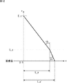
また、適視位置と視位置の奥行き方向の位置が異なる場合、重複画素が発生する。具体的には、図8に示すように、視位置の奥行き方向の位置が適視位置より画面から遠ざかった位置である場合、右目で見える領域のx軸の正方向の端部と左目で見える領域のx軸の負方向の端部が重複する。一方、視位置の奥行き方向の位置が適視位置より画面から近づいた位置である場合、右目で見える領域のx軸の負方向の端部と左目で見える領域のx軸の正方向の端部が重複する。 In addition, when the appropriate viewing position and the position of the viewing position in the depth direction are different, overlapping pixels are generated. Specifically, as shown in FIG. 8, when the position of the viewing position in the depth direction is a position farther from the screen than the appropriate viewing position, it is seen by the positive end of the x axis in the region seen by the right eye and the left eye. The ends in the negative direction of the x-axis of the region overlap. On the other hand, when the position in the depth direction of the viewing position is closer to the screen than the appropriate viewing position, the end in the negative direction of the x-axis of the region visible with the right eye and the end of the positive direction in the x-axis of the region visible with the left eye Are duplicated.
従って、図9Aに示すように、視聴者が適視位置に存在する場合、重複画素は発生しないが、図9Bに示すように、視位置の奥行き方向の位置が適視位置より画面から遠ざかった位置である場合、例えば、右目用の画像が割り当てられたx軸の正方向の端部のサブ画素と左目用の画像が割り当てられたx軸の負方向の端部のサブ画素が重複画素となる。 Therefore, as shown in FIG. 9A, when the viewer is present at the proper viewing position, no overlapping pixels are generated, but as shown in FIG. 9B, the position in the depth direction of the viewing position is farther from the screen than the suitable viewing position. In the case of the position, for example, the sub-pixel at the end in the positive direction of the x axis to which the image for the right eye is assigned and the sub pixel at the end in the negative direction of the x axis to which the image for the left eye is assigned Become.
また、図9Cに示すように、視位置の奥行き方向の位置が適視位置より画面から近づいた位置である場合、例えば、左目用の画像が割り当てられたx軸の正方向の端部のサブ画素と右目用の画像が割り当てられたx軸の負方向の端部のサブ画素が重複画素となる。 Further, as shown in FIG. 9C, when the position in the depth direction of the viewing position is closer to the screen than the appropriate viewing position, for example, the sub-axis at the end in the positive direction of the x-axis to which the left-eye image is assigned. The sub-pixel at the end in the negative direction of the x-axis to which the pixel and the right-eye image are assigned is an overlapping pixel.
従って、クロストークが目立たない高画質の3D画像を容易に表示することはできなかった。 Accordingly, it has been impossible to easily display a high-quality 3D image in which crosstalk is not conspicuous.
本技術は、このような状況に鑑みてなされたものであり、クロストークが目立たない高画質の3D画像を容易に表示することができるようにするものである。 The present technology has been made in view of such a situation, and makes it possible to easily display a high-quality 3D image in which crosstalk is not conspicuous.
本技術の一側面の画像処理装置は、表示部に表示される3D画像の左目で見える領域と右目で見える領域を限定する遮光部上の前記3D画像の各画素の位相を計算する位相計算部と、前記位相計算部により計算された前記位相に基づいて、前記画素ごとに、前記3D画像を構成する左目用の画像と右目用の画像を合成するブレンド処理部とを備える画像処理装置である。 An image processing apparatus according to an aspect of the present technology includes a phase calculation unit that calculates a phase of each pixel of the 3D image on the light-shielding unit that limits a region seen by the left eye and a region seen by the right eye of the 3D image displayed on the display unit And a blend processing unit that synthesizes the image for the left eye and the image for the right eye constituting the 3D image for each pixel based on the phase calculated by the phase calculation unit. .
本技術の一側面の画像処理方法およびプログラムは、本技術の一側面の画像処理装置に対応する。 An image processing method and a program according to an aspect of the present technology correspond to an image processing apparatus according to an aspect of the present technology.
本技術の一側面においては、表示部に表示される3D画像の左目で見える領域と右目で見える領域を限定する遮光部上の前記3D画像の各画素の位相が計算され、前記位相に基づいて、前記画素ごとに、前記3D画像を構成する左目用の画像と前記右目用の画像のブレンド比が計算され、前記ブレンド比に基づいて、前記画素ごとに、前記左目用の画像と前記右目用の画像が合成される。 In one aspect of the present technology, the phase of each pixel of the 3D image on the light-shielding unit that limits the region seen by the left eye and the region seen by the right eye of the 3D image displayed on the display unit is calculated, and based on the phase , A blend ratio between the left-eye image and the right-eye image constituting the 3D image is calculated for each pixel, and the left-eye image and the right-eye image are calculated for each pixel based on the blend ratio. Are synthesized.
本技術の一側面によれば、クロストークが目立たない高画質の3D画像を容易に表示することができる。 According to one aspect of the present technology, it is possible to easily display a high-quality 3D image in which crosstalk is not noticeable.
<第1実施の形態>
<画像処理装置の第1実施の形態の構成例>
図10は、本技術を適用した画像処理装置の第1実施の形態の構成例を示すブロック図である。
<First embodiment>
<Example of Configuration of First Embodiment of Image Processing Apparatus>
FIG. 10 is a block diagram illustrating a configuration example of the first embodiment of the image processing apparatus to which the present technology is applied.
図10の画像処理装置100は、顔検出部101、座標計算部102、位相計算部103、ブレンド比計算部104、L射影変換部105、R射影変換部106、ブレンド処理部107、およびレンチキュラレンズ109が貼り付けられた表示部108により構成される。画像処理装置100は、視聴者の視位置に基づいて、左目用の画像と右目用の画像を混合して表示させる。
10 includes a face detection unit 101, a coordinate
具体的には、画像処理装置100の顔検出部101は、視聴者を撮像し、視聴者の画像を取得する。顔検出部101は、視聴者の画像から顔画像を検出し、顔画像から眉間の位置を検出する。顔検出部101は、眉間の位置を座標計算部102、L射影変換部105、およびR射影変換部106に供給する。
Specifically, the face detection unit 101 of the
なお、顔検出部101は、顔画像の重心の位置を眉間の位置として求めるようにしてもよい。また、顔検出部101は、顔画像から左目と右目の位置を検出し、その位置の中心を眉間の位置として認識するようにしてもよい。 Note that the face detection unit 101 may obtain the position of the center of gravity of the face image as the position between the eyebrows. Further, the face detection unit 101 may detect the positions of the left eye and the right eye from the face image, and recognize the center of the position as the position between the eyebrows.
座標計算部102は、顔検出部101から供給される眉間の位置と、外部から入力される各サブ画素の画面上の座標とに基づいて、各サブ画素の眉間の位置を基準としたレンチキュラレンズ109上の座標を計算し、位相計算部103に供給する。
The coordinate
位相計算部103は、座標計算部102から供給される各サブ画素の座標に基づいて、各サブ画素の眉間の位置を基準としたレンチキュラレンズ109上の位相を計算し、ブレンド比計算部104に供給する。
The
ブレンド比計算部104は、位相計算部103から供給される各サブ画素の位相に基づいて、各サブ画素の左目用の画像と右目用の画像のブレンド比を決定し、ブレンド処理部107に供給する。
The blend
L射影変換部105は、外部から入力される左目用の画像を取得する。L射影変換部105は、顔検出部101から供給される眉間の位置と、外部から入力される各サブ画素の画面上の座標とに基づいて、左目用の画像を射影変換する。L射影変換部105は、射影変換後の左目用の画像をブレンド処理部107に供給する。
The L
R射影変換部106は、外部から入力される右目用の画像を取得する。R射影変換部106は、顔検出部101から供給される眉間の位置と、外部から入力される各サブ画素の画面上の座標とに基づいて、右目用の画像を射影変換する。R射影変換部106は、射影変換後の右目用の画像をブレンド処理部107に供給する。
The R
ブレンド処理部107は、ブレンド比計算部104から供給される各サブ画素のブレンド比に基づいて、L射影変換部105からの左目用の画像とR射影変換後106からの右目用の画像をサブ画素ごとに合成する。ブレンド処理部107は、各サブ画素の合成後の画像を3D画像として表示部108に供給することにより、3D画像を表示させる。
Based on the blend ratio of each sub-pixel supplied from the blend
表示部108は、ブレンド処理部107から供給される3D画像を表示する。また、表示部108には、表示部108に対して斜め方向にレンチキュラレンズ109が貼り付けられている。レンチキュラレンズ109は、表示部108に表示される3D画像の左目で見える領域と右目で見える領域を限定する遮光部として機能する。視聴者は、表示部108に表示された3D画像を、レンチキュラレンズ109を介して見ることにより、立体視を行う。
The
<各サブ画素の眉間の位置を基準としたレンチキュラレンズ上の座標の計算の第1の例>
図11は、座標計算部102による各サブ画素の眉間の位置を基準としたレンチキュラレンズ109上の座標の計算の第1の例を説明する図である。
<First example of calculation of coordinates on lenticular lens with reference to position between eyebrows of each sub-pixel>
FIG. 11 is a diagram illustrating a first example of calculation of coordinates on the
なお、本明細書では、特に断りのない限り、画面内のx軸と垂直な軸をy軸とし、表示部108の表示面に垂直な方向の軸をz軸とする。表示部108の表示面(画像面)のz軸の座標を0とする。
In this specification, unless otherwise specified, an axis perpendicular to the x axis in the screen is defined as a y axis, and an axis perpendicular to the display surface of the
図11では、各サブ画素の眉間の位置を基準としたレンチキュラレンズ109上の座標の計算は、表示部108からの光のレンチキュラレンズ109による屈折を考慮せずに行われる。具体的には、図11に示すように、視位置のx座標、y座標、z座標を、それぞれ、E_x,E_y,E_zとし、レンチキュラレンズ109上のx座標およびy座標、並びに表示部108の表示面上のガラスの厚みを、それぞれ、L_x,L_y,L_zとしたとき、サブ画素のx座標I_xとy座標I_yが以下の式(1)で定義される。
In FIG. 11, the calculation of the coordinates on the
従って、座標計算部102は、眉間の位置を視位置のx座標E_x、y座標E_y、z座標E_zとし、各サブ画素の画面上の座標をサブ画素のx座標I_xおよびy座標I_yとして式(1)に代入するとともに、厚みL_zを式(1)に代入して式(1)を演算する。そして、座標計算部102は、演算の結果得られる各サブ画素のレンチキュラレンズ109上のx座標L_xとy座標L_yを、各サブ画素の眉間の位置を基準としたレンチキュラレンズ109上の座標とする。
Accordingly, the coordinate
<各サブ画素の眉間の位置を基準としたレンチキュラレンズ上の座標の計算の第2の例>
図12は、座標計算部102による各サブ画素の眉間の位置を基準としたレンチキュラレンズ109上の座標の計算の第2の例を説明する図である。
<Second example of calculation of coordinates on lenticular lens with reference to position between eyebrows of each sub-pixel>
FIG. 12 is a diagram for explaining a second example of calculation of coordinates on the
図12では、各サブ画素の眉間の位置を基準としたレンチキュラレンズ109上の座標の計算は、表示部108からの光のレンチキュラレンズ109による屈折を厳密に考慮して行われる。具体的には、図12に示すように、レンチキュラレンズ109から視位置への出射角thが、視位置のz座標E_z、レンチキュラレンズ109上のx座標L_x、および表示部108の表示面上のガラスの厚みL_zを用いて、以下の式(2)で定義される。
In FIG. 12, the calculation of the coordinates on the
![]()
![]()
また、表示部108の表示面上のガラスの屈折率をNとしたとき、出射角thで出射される光のレンチキュラレンズ109への入射角th´が、以下の式(3)で定義される。
Further, when the refractive index of the glass on the display surface of the
![]()
![]()
従って、入射角th´は、以下の式(4)で表される。 Therefore, the incident angle th ′ is expressed by the following equation (4).
![]()
![]()
また、サブ画素のx座標I_x´は、以下の式(5)で定義される。 Further, the x-coordinate I_x ′ of the sub-pixel is defined by the following formula (5).
従って、式(2)、式(4)、および式(5)により、サブ画素のx座標I_x´は、式(6)で表される。 Therefore, the x-coordinate I_x ′ of the sub-pixel is expressed by Expression (6) according to Expression (2), Expression (4), and Expression (5).
同様に、サブ画素のy座標I_y´は、以下の式(7)で表される。 Similarly, the y coordinate I_y ′ of the sub-pixel is expressed by the following formula (7).
従って、座標計算部102は、眉間の位置を視位置のx座標E_x、y座標E_y、z座標E_zとし、各サブ画素の画面上の座標をサブ画素のx座標I_x´およびy座標I_y´として式(6)と式(7)に代入するとともに、厚みL_zと屈折率Nを式(6)と式(7)に代入する。そして、座標計算部102は、代入された式(6)と式(7)を用いて、テーブルやイタレーションにより、各サブ画素のレンチキュラレンズ109上のx座標L_xとy座標L_yを演算する。そして、座標計算部102は、演算の結果得られる各サブ画素のレンチキュラレンズ109上x座標L_xとy座標L_yを、各サブ画素の眉間の位置を基準としたレンチキュラレンズ109上の座標とする。
Accordingly, the coordinate
<各サブ画素の眉間の位置を基準としたレンチキュラレンズ上の座標の計算の第3の例>
図13は、座標計算部102による各サブ画素の眉間の位置を基準としたレンチキュラレンズ109上の座標の計算の第3例を説明する図である。
<Third example of calculation of coordinates on lenticular lens based on position between eyebrows of each sub-pixel>
FIG. 13 is a diagram for explaining a third example of calculation of coordinates on the
図13では、各サブ画素の眉間の位置を基準としたレンチキュラレンズ109上の座標の計算は、表示部108からの光のレンチキュラレンズ109による屈折を近似して行われる。具体的には、図13に示すように、屈折がなく、実際の表示部108の表示面上のガラスの厚みL_zを屈折率Nで除算した値L_z/Nが表示部108の表示面上のガラスの厚みであると仮定したときに視位置へ出射される光の画面上の位置と同一の位置の光が、屈折して視位置へ出射されると近似される。
In FIG. 13, the calculation of the coordinates on the
この場合、視位置のz座標E_z、並びに、レンチキュラレンズ109のx座標L_xおよびy座標L_yを用いて、サブ画素のx座標I_x´´とサブ画素のy座標I_y´´はそれぞれ、以下の式(8)で定義される。
In this case, using the z-coordinate E_z of the viewing position and the x-coordinate L_x and y-coordinate L_y of the
従って、座標計算部102は、眉間の位置を視位置のx座標E_x、y座標E_y、z座標E_zとし、各サブ画素の画面上の座標をサブ画素のx座標I_x´´およびy座標I_y´´として式(8)に代入するとともに、厚みL_zと屈折率Nを式(8)に代入して式(8)を演算する。そして、座標計算部102は、演算の結果得られる各サブ画素のレンチキュラレンズ109上のx座標L_xとy座標L_yを、各サブ画素の眉間の位置を基準としたレンチキュラレンズ109上の座標とする。
Therefore, the coordinate
なお、上述した式(6)と式(7)において、出射角thが十分小さいとすると、以下の式(9)が成り立つ。 In the above-described formulas (6) and (7), if the emission angle th is sufficiently small, the following formula (9) is established.
![]()
![]()
従って、この場合、以下の式(10)に示すように、式(6)で演算されるサブ画素のx座標I_x´´と式(8)で演算されるサブ画素のx座標I_x´´は一致する。 Therefore, in this case, as shown in the following equation (10), the x-coordinate I_x ″ of the sub-pixel calculated by the equation (6) and the x-coordinate I_x ″ of the sub-pixel calculated by the equation (8) are Match.
同様に、式(7)で演算されるサブ画素のy座標I_y´´と式(8)で演算されるサブ画素のy座標I_y´´は一致する。 Similarly, the y-coordinate I_y ″ of the sub-pixel calculated by Expression (7) matches the y-coordinate I_y ″ of the sub-pixel calculated by Expression (8).
従って、図13における近似は、出射角thが十分小さいとした近似であるといえる。 Therefore, it can be said that the approximation in FIG. 13 is an approximation in which the emission angle th is sufficiently small.
図12や図13に示したように、光の屈折を考慮して計算が行われる場合には、視位置が表示部108に近く、光の屈折の影響が大きい場合であっても、正確な各サブ画素の眉間の位置を基準としたレンチキュラレンズ109上の座標を計算することができる。
As shown in FIG. 12 and FIG. 13, when the calculation is performed in consideration of light refraction, even if the viewing position is close to the
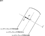
また、図11乃至図13の計算では、図14Aに示すように、レンチキュラレンズ109のz座標L_zが一定であるものとしたが、レンチキュラレンズ109はシート状であるため、実際には、図14Bに示すように、z座標L_zは一定ではない。即ち、レンチキュラレンズ109のz座標L_zは、レンチキュラレンズ109上のx座標L_xおよびy座標L_yに応じて異なる。
In addition, in the calculations of FIGS. 11 to 13, the z coordinate L_z of the
従って、座標計算部102は、レンチキュラレンズ109のz座標L_zの変化を考慮して、以下の式(11)で定義されるL_x[x]とL_y[y]を、各サブ画素の眉間の位置を基準としたレンチキュラレンズ109上の座標とすることもできる。
Therefore, the coordinate
なお、式(11)において、xは、サブ画素のx座標I_x(I_x´,I_x´´)を表し、yは、サブ画素のy座標I_y(I_y´,I_y´´)を表す。 In Expression (11), x represents the x coordinate I_x (I_x ′, I_x ″) of the sub pixel, and y represents the y coordinate I_y (I_y ′, I_y ″) of the sub pixel.
このように、レンチキュラレンズ109のz座標L_zの変化を考慮して計算が行われる場合には、表示部108が大型の液晶パネルなどであって、レンチキュラレンズ109の表示部108に対する浮きが大きい場合であっても、正確な各サブ画素の眉間の位置を基準としたレンチキュラレンズ109上の座標を計算することができる。
As described above, when the calculation is performed in consideration of the change of the z coordinate L_z of the
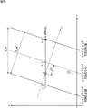
<位相の計算の例>
図15は、図10の位相計算部103による位相の計算の例を説明する図である。
<Example of phase calculation>
FIG. 15 is a diagram for explaining an example of phase calculation by the
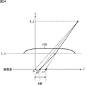
図15に示すように、レンチキュラレンズ109の表示部108に対する傾きをL_thとする場合、レンチキュラレンズ109上のy座標L_yに基づくx座標L_xのオフセットL_xyは、以下の式(12)で表される。
As shown in FIG. 15, if the L_th an inclination with respect to the
![]()
![]()
位相計算部103は、このオフセットL_xyを用いて、レンチキュラレンズ109上の位相phaseCを、以下の式(13)により求める。
なお、式(13)において、L_wは、図15に示すように、レンチキュラレンズ109の幅を表す。式(13)によれば、各レンチキュラレンズ109のx座標L_xが最小値である場合位相phaseCは-0.5となり、x座標L_xが中間値である場合位相phaseCは0となり、x座標L_xが最大値である場合位相phaseCは0.5となる。
In Expression (13), L_w represents the width of the
<ブレンド比の例>
図16は、位相phaseCと左目用の画像および右目用の画像のブレンド比の関係の例を示す図である。
<Example of blend ratio>
FIG. 16 is a diagram illustrating an example of the relationship between the phase phase C and the blend ratio of the image for the left eye and the image for the right eye.
ここで、図2に示したように、左目で見える領域は、右目で見える領域に対してx軸の正の方向であり、右側で見える領域は、左目で見える領域に対してx軸の負の方向である。従って、位相phaseCが0以下であるサブ画素には、右目用の画像が割り当てられ、位相phaseCが0より大きいサブ画素には、左目用の画像が割り当てられる。 Here, as shown in FIG. 2, the region seen by the left eye is in the positive direction of the x axis relative to the region seen by the right eye, and the region seen by the right eye is negative of the x axis relative to the region seen by the left eye. Direction. Accordingly, the right-eye image is assigned to the sub-pixels whose phase phase C is 0 or less, and the left-eye image is assigned to the sub-pixels whose phase phase C is greater than 0.
よって、図16の例では、サブ画素の位相phaseCが-0.5付近より大きく0付近の負の値より小さい場合、そのサブ画素の右目用の画像のブレンド比rate_rは1であり、左目用の画像のブレンド比rate_lは0である。これにより、図17に示すように、位相phaseCが-0.5付近より大きく0付近の負の値より小さいサブ画素は、右目用の画像となる。 Therefore, in the example of FIG. 16, when the phase phase C of a sub-pixel is larger than about −0.5 and smaller than a negative value near 0, the blend ratio rate_r of the right-eye image of the sub-pixel is 1, and The blend ratio rate_l of the image is 0. As a result, as shown in FIG. 17, sub-pixels whose phase phase C is greater than around -0.5 and less than a negative value near 0 become an image for the right eye.
また、サブ画素の位相phaseCが0付近の正の値より大きく0.5付近より小さい場合、そのサブ画素の左目用の画像のブレンド比rate_lは1であり、右目用の画像のブレンド比rate_rは0である。これにより、図17に示すように、位相phaseCが0付近の正の値より大きく0.5付近より小さいサブ画素は、左目用の画像となる。 If the phase phase C of the sub-pixel is larger than a positive value near 0 and smaller than about 0.5, the blend ratio rate_l of the image for the left eye of the sub-pixel is 1, and the blend ratio rate_r of the image for the right eye is 0. It is. As a result, as shown in FIG. 17, sub-pixels whose phase phase C is larger than a positive value near 0 and smaller than 0.5 become an image for the left eye.
また、サブ画素の位相phaseCが±0.5付近および0付近である場合、そのサブ画素の左目用の画像のブレンド比rate_lと右目用の画像のブレンド比rate_rは、0より大きい。具体的には、位相phaseCが-0.5より大きくなるにつれて、即ち右目で見える領域の中心に近づくにつれて、ブレンド比rate_lは0に近づき、ブレンド比rate_rは1に近づく。 When the phase phase C of the sub-pixel is around ± 0.5 and near 0, the blend ratio rate_l of the left-eye image and the blend ratio rate_r of the right-eye image of the sub-pixel are larger than zero. Specifically, the blend ratio rate_l approaches 0 and the blend ratio rate_r approaches 1 as the phase phase C becomes larger than −0.5, that is, as the center of the region visible with the right eye is approached.
また、位相phaseCが0付近の負の値から0付近の正の値に近づくにつれて、即ち左目で見える領域の中心に近づくにつれて、ブレンド比rate_lは1に近づき、ブレンド比rate_rは0に近づく。また、位相phaseCが0.5に近づくにつれて、即ち右目で見える領域の中心に近づくにつれて、ブレンド比rate_lは0に近づき、ブレンド比rate_rは1に近づく。 Further, as the phase phase C approaches from a negative value near 0 to a positive value near 0, that is, as it approaches the center of the region visible to the left eye, the blend ratio rate_l approaches 1 and the blend ratio rate_r approaches 0. Further, as the phase phase C approaches 0.5, that is, as the center of the region visible with the right eye approaches, the blend ratio rate_l approaches 0 and the blend ratio rate_r approaches 1.
以上のように、図16の例では、サブ画素の位相phaseCが±0.5付近および0付近である場合、そのサブ画素の左目用の画像のブレンド比rate_lと右目用の画像のブレンド比rate_rは0より大きくなるので、サブ画素は、左目用の画像と右目用の画像が合成された画像となる。 As described above, in the example of FIG. 16, when the phase phase C of the sub-pixel is around ± 0.5 and near 0, the blend ratio rate_l of the image for the left eye and the blend ratio rate_r of the image for the right eye of the sub-pixel are Since it becomes larger than 0, the sub-pixel is an image obtained by combining the left-eye image and the right-eye image.
ここで、図7や図9に示した重複画素は、左目用の画像が割り当てられた領域や右目用の画像が割り当てられた領域の境目で発生する。即ち、重複画素は、位相phaseCが±0.5付近または0付近であるサブ画素である。従って、図16に示したようにブレンド比が決定され、位相phaseCが±0.5付近および0付近であるサブ画素が、左目用の画像と右目用の画像が合成された画像となることにより、クロストークが目立たなくなる。 Here, the overlapping pixels shown in FIGS. 7 and 9 occur at the boundary between the area to which the image for the left eye is assigned and the area to which the image for the right eye is assigned. That is, the overlapping pixel is a sub-pixel whose phase phase C is around ± 0.5 or around 0. Therefore, the blend ratio is determined as shown in FIG. 16, and the sub-pixels whose phase phase C is around ± 0.5 and near 0 become an image obtained by combining the image for the left eye and the image for the right eye, Crosstalk is not noticeable.
<射影変換の説明>
図18は、表示部108に表示される画像の見え方を説明する図である。
<Explanation of projective transformation>
FIG. 18 is a diagram for explaining how an image displayed on the
図18に示すように、表示部108には、表示部108に対して斜め方向にレンチキュラレンズ109が貼り付けられている。従って、表示部108に表示される画像は、斜め方向に拡大される。
As shown in FIG. 18, a
従って、斜め方向の拡大を考慮せずに3D画像がそのまま表示部108に表示されると、文字がにじんで見えたり、直線にざらつきが見えたりする。そこで、L射影変換部105とR射影変換部106は、表示部108の各サブ画素の画面上の座標(I_x,I_y)を実際に視聴者に見える画面上の座標に射影変換(以下、座標変換という)する。
Therefore, when a 3D image is displayed on the
そして、L射影変換部105は、外部から入力される左目用の画像から射影変換後の座標に対応する左目用の画像を生成することにより、左目用の画像の射影変換を行う。また、R射影変換部106は、外部から入力される右目用の画像から射影変換後の座標に対応する右目用の画像を生成することにより、右目用の画像の射影変換を行う。
Then, the L
以下に、座標変換について説明する。 The coordinate conversion will be described below.
ここで、まず、図19に示すように、レンチキュラレンズ109の境界に対して垂直な方向の軸をx´軸とする。また、レンチキュラレンズ109の中心を通って視位置に出射される画像の画面(斜め方向に拡大された画面)上の位置のx´座標を0とする。
Here, first, as shown in FIG. 19, the axis in the direction perpendicular to the boundary of the
また、表示部108の各サブ画素の画面上の座標(I_x,I_y)のx´座標をx0´とし、そのサブ画素の画像が視位置で見える画面(斜め方向に拡大された画面)上の座標のx´座標をx1´とする。
Further, the x ′ coordinate of the coordinates (I_x, I_y) of each sub-pixel of the
図20は、視位置のx´座標がレンチキュラレンズ109の中心のx´座標と同一である場合の座標x0´と座標x1´の関係を示す図である。
FIG. 20 is a diagram illustrating the relationship between the coordinates x0 ′ and the coordinates x1 ′ when the x ′ coordinate of the viewing position is the same as the x ′ coordinate of the center of the
図20の左側に示すように、レンチキュラレンズ109がない場合に視位置から座標x0´の位置に見える画像は、図20の右側に示すように、レンチキュラレンズ109があり、視位置のx´座標がレンチキュラレンズ109の中心のx´座標と同一である場合、視位置から座標x1´の位置に見える。
As shown on the left side of FIG. 20, when the
ここで、レンチキュラレンズ109を通過する画像は、レンチキュラレンズ109の中心を基準として拡大される。従って、座標x1´は、座標x0´のレンチキュラレンズ109の拡大率A倍である。
Here, the image passing through the
図21は、視位置のx´座標がレンチキュラレンズ109の中心のx´座標より小さい場合の座標x0´と座標x1´の関係を示す図である。
FIG. 21 is a diagram showing the relationship between the coordinates x0 ′ and the coordinates x1 ′ when the x ′ coordinate of the viewing position is smaller than the x ′ coordinate of the center of the
レンチキュラレンズ109を通過する画像は、レンチキュラレンズ109の中心を基準として拡大されるので、座標x1´は、図21に示すように座標x0´の拡大率A倍となる。
Since the image passing through the
図21に示すように、視位置のx´座標がレンチキュラレンズ109の中心のx´座標より小さい場合、図20の場合に比べて、x´座標0はx´軸の正の方向に移動するため、座標x1´と座標x0´は大きくなる。
As shown in FIG. 21, when the x ′ coordinate of the viewing position is smaller than the x ′ coordinate of the center of the
図22乃至図24は、視位置のx´座標がレンチキュラレンズ109の中心のx´座標より大きい場合の座標x0´と座標x1´の関係を示す図である。
22 to 24 are diagrams showing the relationship between the coordinates x0 'and the coordinates x1' when the x 'coordinate of the viewing position is larger than the x' coordinate of the center of the
レンチキュラレンズ109を通過する画像は、レンチキュラレンズ109の中心を基準として拡大されるので、座標x1´は、図22乃至図24に示すように座標x0´の拡大率A倍となる。
Since the image passing through the
また、図22に示すように、視位置のx´座標がレンチキュラレンズ109の中心のx´座標より少しだけ大きい場合、図20の場合に比べて、x´座標0はx´軸の負の方向に移動するため、座標x1´と座標x0´は小さくなる。
Further, as shown in FIG. 22, when the x ′ coordinate of the viewing position is slightly larger than the x ′ coordinate of the center of the
そして、図23に示すように、視位置のx´座標がレンチキュラレンズ109の中心のx´座標よりさらに少しだけ大きくなると、座標x0´と座標x1´が両方とも0になる。
Then, as shown in FIG. 23, when the x ′ coordinate of the viewing position becomes slightly larger than the x ′ coordinate of the center of the
さらに、図24に示すように、視位置のx´座標がレンチキュラレンズ109の中心のx´座標より非常に大きくなると、座標x0´が正の値となるため、図20乃至図23の場合に比べて、座標x0´から座標x1´への移動方向が反転する。
Furthermore, as shown in FIG. 24, when the x ′ coordinate of the viewing position becomes much larger than the x ′ coordinate of the center of the
以上のように、座標x1´は、拡大率Aと視位置のx´座標とに基づいて座標x0´から変換される。 As described above, the coordinate x1 ′ is converted from the coordinate x0 ′ based on the magnification A and the x ′ coordinate of the viewing position.
具体的には、まず最初に、座標x0´が求められる。座標x0´は、レンチキュラレンズ109の中心からの相対距離である。よって、まず、図25に示すように、レンチ幅L_w、視位置のz座標E_z、および表示部108の表示面上のガラスの厚みL_zを用いて、以下の式(14)により、画面上のx軸方向のレンチ幅L_w´が求められる。
Specifically, first, the coordinate x0 ′ is obtained. The coordinate x0 ′ is a relative distance from the center of the
![]()
![]()
次に、図26に示すように、以下の式(15)により、レンチキュラレンズ109の傾きthとレンチ幅L_w´を用いて、画面上のx´軸方向のレンチ幅L_w´´が求められる。
Next, as shown in FIG. 26, the wrench width L_w ″ in the x′-axis direction on the screen is obtained by using the inclination th of the
![]()
![]()
そして、以下の式(16)により、レンチ幅L_w´´と各サブ画素の位相phaseCを用いて、各サブ画素の座標x0´が求められる。 Then, using the wrench width L_w ″ and the phase phase C of each sub-pixel, the coordinate x0 ′ of each sub-pixel is obtained by the following equation (16).
![]()
![]()
次に、図27に示すように、座標x1´が、以下の式(17)により、座標x0´と拡大率Aを用いて求められる。 Next, as shown in FIG. 27, the coordinate x1 ′ is obtained using the coordinate x0 ′ and the enlargement factor A by the following equation (17).
![]()
![]()
また、座標x1´と座標x0´の差分dx´は、以下の式(18)で表される。 Further, the difference dx ′ between the coordinates x1 ′ and the coordinates x0 ′ is expressed by the following equation (18).
![]()
![]()
次に、サブ画素の差分dx´、x座標I_x、およびy座標I_yを用いて、そのサブ画素の実際に視聴者に見える画面(斜め方向に拡大された画面)上の位置のx座標x1とy座標y1が求められる。具体的には、まず、図28に示すように、以下の式(19)により差分dx´から、x軸上の差分dxとy軸上の差分dyが求められる。 Next, using the sub-pixel difference dx ′, the x-coordinate I_x, and the y-coordinate I_y, the x-coordinate x1 of the position of the sub-pixel on the screen that is actually visible to the viewer (screen enlarged in an oblique direction) The y coordinate y1 is obtained. Specifically, first, as shown in FIG. 28, the difference dx on the x axis and the difference dy on the y axis are obtained from the difference dx ′ by the following equation (19).
次に、以下の式(20)により、移動量dxと移動量dyから座標x1と座標y1が求められる。 Next, the coordinate x1 and the coordinate y1 are obtained from the movement amount dx and the movement amount dy by the following equation (20).
L射影変換部105とR射影変換部106は、それぞれ、以上のような演算を行い、表示部108の各サブ画素の画面上の座標(I_x,I_y)を実際に視聴者に見える画面上の座標(x1,y1)に座標変換する。
The L
そして、L射影変換部105とR射影変換部106は、それぞれ、左目用の画像、右目用の画像から、各サブ画素の座標(x1,y1)の画像を生成する。具体的には、座標(x1,y1)が、左目用の画像(または右目用の画像)のサブ画素の座標(I_x,I_y)である場合、L射影変換部105(R射影変換部106)は、そのサブ画素の画素値を生成する。
Then, the L
一方、座標(x1,y1)が、左目用の画像(または右目用の画像)のサブ画素の座標(I_x,I_y)ではない場合、L射影変換部105(R射影変換部106)は、図29に示すように、例えば、座標(x1,y1)の左上、右上、左下、および右下の同一の色のサブ画素の画素値を用いて、座標(x1,y1)の画素値を生成する。そして、L射影変換部105とR射影変換部106は、それぞれ、生成された各サブ画素の座標(x1,y1)の画像を、そのサブ画素の射影変換後の画像とする。
On the other hand, when the coordinates (x1, y1) are not the coordinates (I_x, I_y) of the sub-pixels of the image for the left eye (or the image for the right eye), the L projection conversion unit 105 (R projection conversion unit 106) As shown in FIG. 29, for example, the pixel values of the coordinates (x1, y1) are generated using the pixel values of the sub-pixels of the same color at the upper left, upper right, lower left, and lower right of the coordinates (x1, y1). . Then, the L
<L射影変換部とR射影変換部の構成例>
図30は、図10のL射影変換部105とR射影変換部106の構成例を示すブロック図である。
<Configuration Examples of L Projection Conversion Unit and R Projection Conversion Unit>
30 is a block diagram illustrating a configuration example of the L
図30に示すように、L射影変換部105は、座標計算部121、位相計算部122、相対距離計算部123、座標変換部124、座標計算部125、および画像変換部126により構成される。
As shown in FIG. 30, the L
L射影変換部105の座標計算部121は、図10の座標計算部102と同様に、顔検出部101から供給される眉間の位置と、外部から入力される各サブ画素の画面上の座標とに基づいて、式(1)、式(6)および式(7)、または式(8)により、各サブ画素の眉間の位置を基準としたレンチキュラレンズ109上の座標(L_x,L_y)を計算する。座標計算部121は、各サブ画素の座標(L_x,L_y)を位相計算部122に供給する。
Similar to the coordinate
位相計算部122は、位相計算部103と同様に、座標計算部121から供給される各サブ画素の座標(L_x,L_y)に基づいて、上述した式(13)により、各サブ画素の眉間の位置を基準としたレンチキュラレンズ109上の位相phaseCを計算する。位相計算部122は、位相phaseCを相対距離計算部123に供給する。
Similarly to the
相対距離計算部123は、位相計算部122から供給される各サブ画素の位相phaseCと、顔検出部101から供給される眉間の位置とに基づいて、上述した式(14)乃至(16)により各サブ画素の座標x0´を求める。相対距離計算部123は、座標x0´を座標変換部124と座標計算部125に供給する。
The relative
座標変換部124は、相対距離計算部123から供給される各サブ画素の座標x0´に基づいて、上述した式(17)により各サブ画素の座標x1´を求め、座標計算部125に供給する。
The coordinate
座標計算部125は、相対距離計算部123からの各サブ画素の座標x0´、座標変換部124からの各サブ画素の座標x1´、および外部から入力される各サブ画素の画面上の座標に基づいて、上述した式(18)乃至(20)により各サブ画素の座標(x1,y1)を求める。そして、座標計算部125は、各サブ画素の座標(x1,y1)wを画像変換部126に供給する。
The coordinate
画像変換部126は、座標変換部124から供給される各サブ画素の座標(x1,y1)に基づいて、サブ画素ごとに、外部から入力される左目用の画像から座標(x1,y1)の左目用の画像を生成することにより、左目用の画像を射影変換する。画像変換部126は、射影変換後の左目用の画像を図10のブレンド処理部107に供給する。
Based on the coordinates (x1, y1) of each sub-pixel supplied from the coordinate
R射影変換部106は、座標計算部131、位相計算部132、相対距離計算部133、座標変換部134、座標計算部135、および画像変換部136により構成される。R射影変換部106の各部の処理は、左目用の画像の代わりに右目用の画像を用いることを除いて、L射影変換部105の対応する部の処理と同様であるので、説明は省略する。
The R
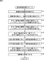
<画像処理装置の処理の説明>
図31は、図10の画像処理装置100の表示制御処理を説明するフローチャートである。この表示制御処理は、例えば、左目用の画像と右目用の画像が画像処理装置100に入力されたときに開始される。
<Description of processing of image processing apparatus>
FIG. 31 is a flowchart for explaining display control processing of the
図31のステップS11において、画像処理装置100の顔検出部101は、視聴者を撮像し、視聴者の画像を取得する。ステップS12において、顔検出部101は、視聴者の画像から顔画像を検出し、顔画像から眉間の位置を検出する。顔検出部101は、眉間の位置を座標計算部102、L射影変換部105、およびR射影変換部106に供給する。
In step S <b> 11 of FIG. 31, the face detection unit 101 of the
ステップS13において、座標計算部102は、顔検出部101から供給される眉間の位置と、各サブ画素の画面上の座標とに基づいて、式(1)、式(6)および式(7)、または式(8)により、各サブ画素の眉間の位置を基準としたレンチキュラレンズ109上の座標(L_x,L_y)を計算する。座標計算部102は、計算された各サブ画素の座標(L_x,L_y)を位相計算部103に供給する。
In step S <b> 13, the coordinate
ステップS14において、位相計算部103は、座標計算部102から供給される各サブ画素の座標(L_x,L_y)に基づいて、上述した式(13)により、各サブ画素の眉間の位置を基準としたレンチキュラレンズ109上の位相phaseCを計算する。位相計算部103は、計算された各サブ画素の位相phaseCをブレンド比計算部104に供給する。
In step S <b> 14, the
ステップS15において、ブレンド比計算部104は、位相計算部103から供給される各サブ画素の位相phaseCに基づいて、各サブ画素の左目用の画像のブレンド比rate_lと右目用の画像のブレンド比rate_rを決定し、ブレンド処理部107に供給する。
In step S15, the blend
ステップS16において、L射影変換部105は、顔検出部101から供給される眉間の位置と各サブ画素の画面上の座標とに基づいて、左目用の画像に対して射影変換処理を行う。この射影変換処理の詳細は、後述する図32を参照して説明する。L射影変換部105は、各サブ画素の射影変換処理後の左目用の画像をブレンド処理部107に供給する。
In step S <b> 16, the L
ステップS17において、R射影変換部106は、L射影変換部105と同様に、顔検出部101から供給される眉間の位置と各サブ画素の画面上の座標とに基づいて、右目用の画像に対して射影変換処理を行う。R射影変換部106は、各サブ画素の射影変換後の右目用の画像をブレンド処理部107に供給する。
In step S <b> 17, the R
ステップS18において、ブレンド処理部107は、ブレンド比計算部104から供給される各サブ画素のブレンド比rate_lとブレンド比rate_rに基づいて、サブ画素ごとに、L射影変換部105からの左目用の画像とR射影変換後106からの右目用の画像を合成する。
In step S <b> 18, the
ステップS19において、ブレンド処理部107は、各サブ画素の合成後の画像を3D画像として表示部108に供給することにより、表示部108に3D画像を表示させる。そして、処理は終了する。
In step S <b> 19, the
図32は、図31のステップS16の射影変換処理の詳細を説明するフローチャートである。 FIG. 32 is a flowchart for explaining the details of the projective transformation process in step S16 of FIG.
図32のステップS31において、L射影変換部105の座標計算部121は、図10の座標計算部102と同様に、顔検出部101から供給される眉間の位置と、外部から入力される各サブ画素の画面上の座標とに基づいて、式(1)、式(6)および式(7)、または式(8)により、各サブ画素の眉間の位置を基準としたレンチキュラレンズ109上の座標(L_x,L_y)を計算する。座標計算部121は、各サブ画素の座標(L_x,L_y)を位相計算部122に供給する。
In step S31 of FIG. 32, the coordinate
ステップS32において、位相計算部122は、位相計算部103と同様に、座標計算部121から供給される各サブ画素の座標(L_x,L_y)に基づいて、上述した式(13)により、各サブ画素の眉間の位置を基準としたレンチキュラレンズ109上の位相phaseCを計算する。位相計算部122は、位相phaseCを相対距離計算部123に供給する。
In step S32, the
ステップS33において、相対距離計算部123は、位相計算部122から供給される各サブ画素の位相phaseCと、顔検出部101から供給される眉間の位置とに基づいて、上述した式(14)乃至(16)により各サブ画素の座標x0´を求める。相対距離計算部123は、座標x0´を座標変換部124と座標計算部125に供給する。
In step S <b> 33, the relative
ステップS34において、座標変換部124は、相対距離計算部123から供給される各サブ画素の座標x0´に基づいて、上述した式(17)により各サブ画素の座標x1´を求め、座標計算部125に供給する。
In step S34, the coordinate
ステップS35において、座標計算部125は、相対距離計算部123からの各サブ画素の座標x0´、座標変換部124からの各サブ画素の座標x1´、および外部から入力される各サブ画素の画面上の座標に基づいて、上述した式(18)乃至(20)により各サブ画素の座標(x1,y1)を求める。そして、座標計算部125は、各サブ画素の座標(x1,y1)wを画像変換部126に供給する。
In step S35, the coordinate
ステップS36において、画像変換部126は、座標変換部124から供給される各サブ画素の座標(x1,y1)に基づいて、サブ画素ごとに、外部から入力される左目用の画像から座標(x1,y1)の左目用の画像を生成することにより、左目用の画像を射影変換する。
In step S <b> 36, the
ステップS37において、画像変換部126は、射影変換後の左目用の画像を図10のブレンド処理部107に出力し、処理を終了する。
In step S37, the
以上のように、画像処理装置100は、各サブ画素のレンチキュラレンズ109上の位相phaseCを計算し、位相phaseCに基づいて、サブ画素ごとに、左目用の画像と右目用の画像を合成する。従って、画像処理装置100は、左目用の画像が割り当てられる領域と右目用の画像が割り当てられる領域の境界のサブ画素において左目用の画像と右目用の画像を合成することができる。その結果、左目用の画像と右目用の画像の境界で発生するクロストークが目立たない高画質の3D画像を容易に生成し、表示することができる。
As described above, the
また、画像処理装置100は、眉間の位置を用いて位相phaseCを求めるので、視位置が変化する場合であっても、正確に、左目用の画像と右目用の画像の境界において左目用の画像と右目用の画像を合成することができる。
Further, since the
<第2実施の形態>
<画像処理装置の第2実施の形態の構成例>
図33は、本技術を適用した画像処理装置の第2実施の形態の構成例を示すブロック図である。
<Second Embodiment>
<Example of Configuration of Second Embodiment of Image Processing Apparatus>
FIG. 33 is a block diagram illustrating a configuration example of an image processing apparatus according to a second embodiment to which the present technology is applied.
図33に示す構成のうち、図10の構成と同じ構成には同じ符号を付してある。重複する説明については適宜省略する。 33, the same reference numerals are given to the same configurations as those in FIG. The overlapping description will be omitted as appropriate.
図33の画像処理装置150の構成は、顔検出部101、ブレンド比計算部104、L射影変換部105、R射影変換部106の代わりに、顔検出部151、ブレンド比計算部158、L射影変換部159、R射影変換部160が設けられる点、座標計算部102の代わりに座標計算部152と座標計算部155が設けられる点、位相計算部103の代わりに位相計算部153と位相計算部156が設けられる点、および新たに面積率計算部154と面積率計算部157が設けられ点が図10の画像処理装置100の構成と異なる。
The configuration of the
図33の画像処理装置150は、各サブ画素における左目で見える領域の面積率と右目で見える領域の面積率とに基づいて、左目用の画像と右目用の画像を合成する。
The
具体的には、顔検出部151は、図10の顔検出部101と同様に、視聴者を撮像し、視聴者の画像を取得する。顔検出部151は、視聴者の画像から顔画像を検出し、顔画像から左目の位置と右目の位置を検出する。顔検出部151は、左目の位置を座標計算部152とL射影変換部159に供給し、右目の位置を座標計算部155とR射影変換部160に供給する。
Specifically, the face detection unit 151 captures the viewer and acquires the viewer's image in the same manner as the face detection unit 101 in FIG. The face detection unit 151 detects a face image from the viewer's image, and detects the position of the left eye and the position of the right eye from the face image. The face detection unit 151 supplies the position of the left eye to the coordinate
座標計算部152は、顔検出部151から供給される左目の位置と、外部から入力される各サブ画素の画面上の座標とに基づいて、各サブ画素の左目の位置を基準としたレンチキュラレンズ109上の座標を計算する。具体的には、座標計算部152は、式(1)、式(6)および式(7)、または式(8)の視位置(E_x,E_y,E_z)として左目の位置を代入した式を演算する。そして、座標計算部152は、演算の結果得られる各サブ画素のレンチキュラレンズ109上の座標(L_x,L_y)を、各サブ画素の左目の位置を基準としたレンチキュラレンズ109上の座標とする。座標計算部152は、計算された各サブ画素の座標を位相計算部153に供給する。
The coordinate
位相計算部153は、座標計算部152から供給される各サブ画素の座標に基づいて、上述した式(13)により、各サブ画素の左目の位置を基準としたレンチキュラレンズ109上の位相を計算し、面積率計算部154に供給する。
The
面積率計算部154は、位相計算部153から供給される各サブ画素の位相に基づいて、各サブ画素における左目で見える領域の面積率を計算し、ブレンド比計算部158に供給する。
Based on the phase of each subpixel supplied from the
座標計算部155、位相計算部156、および面積率計算部157は、左目が右目に代わる点を除いて、座標計算部152、位相計算部153、および面積率計算部154と同一であるので、説明は省略する。
The coordinate
ブレンド比計算部158は、面積率計算部154から供給される各サブ画素における左目で見える領域の面積率と、面積率計算部157から供給される各サブ画素における右目で見える領域の面積率とに基づいて、左目用の画像と右目用の画像のブレンド比を計算する。ブレンド比計算部158は、左目用の画像のブレンド比と右目用の画像のブレンド比をブレンド処理部107に供給する。
The blend
L射影変換部159は、図10のL射影変換部105と同様に、外部から入力される左目用の画像を取得する。L射影変換部159は、顔検出部151から供給される左目の位置と、外部から入力される各サブ画素の画面上の座標とに基づいて、左目用の画像を射影変換する。L射影変換部159は、射影変換後の左目用の画像をブレンド処理部107に供給する。
The L
R射影変換部160は、図10のR射影変換部106と同様に、外部から入力される右目用の画像を取得する。R射影変換部160は、顔検出部151から供給される右目の位置と、外部から入力される各サブ画素の画面上の座標とに基づいて、右目用の画像を射影変換する。R射影変換部160は、各サブ画素の射影変換後の右目用の画像をブレンド処理部107に供給する。
The R
<左目で見える領域と右目で見える領域の視位置による変化の説明>
図34は、左目で見える領域と右目で見える領域の視位置による変化を説明する図である。
<Explanation of changes due to viewing position of the area visible with the left eye and the area visible with the right eye>
FIG. 34 is a diagram for explaining a change depending on the viewing position of the region visible with the left eye and the region visible with the right eye.
なお、図34において、左上がりの斜線の領域は、画面内の右目で見える領域を表し、右上がりの斜線の領域は、画面内の左目で見える領域を表す。また、斜めの実線は、レンチキュラレンズ109の境界を表し、斜めの破線は、レンチキュラレンズ109の中心位置を表す。
In FIG. 34, a diagonally upward-slashed area represents an area visible with the right eye in the screen, and an obliquely upward-slashed area represents an area visible with the left eye in the screen. The oblique solid line represents the boundary of the
図34の2行目に示すように、視位置が適視位置のうちの最適視位置である場合、右目で見える領域と左目で見える領域は重ならず、隣接する。これに対して、視位置が最適視位置以外の適視位置である場合、3乃至5行目に示すように、右目で見える領域と左目で見える領域は重ならないが、右目で見える領域と左目で見える領域の境界の少なくとも1つには、マージンが発生する。 As shown in the second row of FIG. 34, when the viewing position is the optimum viewing position of the suitable viewing positions, the area seen by the right eye and the area seen by the left eye do not overlap and are adjacent. On the other hand, when the viewing position is an appropriate viewing position other than the optimal viewing position, as shown in the third to fifth lines, the area seen by the right eye and the area seen by the left eye do not overlap, but the area seen by the right eye and the left eye A margin occurs at at least one of the boundaries of the region visible in FIG.
一方、視位置が適視位置ではない場合、6乃至10行目に示すように、右目で見える領域と左目で見える領域の境界の少なくとも一方は重なり、重複画素が発生する。この重複画素における左目で見える領域と右目で見える領域の面積率は、視位置に応じて変化する。 On the other hand, when the viewing position is not the proper viewing position, as shown in the 6th to 10th lines, at least one of the boundaries between the area seen by the right eye and the area seen by the left eye overlaps to generate overlapping pixels. The area ratio of the region that can be seen by the left eye and the region that can be seen by the right eye in the overlapping pixel varies depending on the viewing position.
<面積率の計算の説明>
図35は、眉間の位置を基準とした位相phaseCと画面上のレンチキュラレンズ109の幅L_w´の関係を示す図である。
<Description of area ratio calculation>
FIG. 35 is a diagram showing the relationship between the phase phase C with reference to the position between the eyebrows and the width L_w ′ of the
図35に示すように、眉間の位置を視位置とする場合、眉間の位置を基準とした位相phaseCの-0.5以上0.5以下の範囲は、画面上のレンチキュラレンズ109の幅L_w´に対応する。従って、サブ画素の横幅Iwと縦幅をIhは、以下の式(21)により、位相phaseCで正規化することができる。
As shown in FIG. 35, when the position between the eyebrows is set as the viewing position, the range of −0.5 to 0.5 in the phase phase C with respect to the position between the eyebrows corresponds to the width L_w ′ of the
なお、式(21)において、Iw´は、正規化後のサブ画素の横幅Iwであり、Ih´は、正規化後のサブ画素の縦幅Ihである。 In Expression (21), Iw ′ is the horizontal width Iw of the normalized subpixel, and Ih ′ is the vertical width Ih of the normalized subpixel.
図35に示すように、位相phaseCが0付近であるサブ画素は重複画素となる。 As shown in FIG. 35, sub-pixels whose phase phase C is near 0 are overlapping pixels.
図36は、右目の位置を視位置としたときの右目で見える領域を示す図である。 FIG. 36 is a diagram illustrating a region that can be seen by the right eye when the position of the right eye is the viewing position.
図36に示すように、右目の位置を視位置とする場合、拡大率Aが1であるとすると、右目の位置を基準とした位相phaseRの-0.5以上0.5以下の範囲が、右目で見える領域となる。従って、右目で見える領域の位相phaseRの範囲の絶対値の最大値Bは0.5/Aとなる。即ち、右目で見える領域の位相phaseRの範囲は、-0.5/A以上0.5/A以下となる。 As shown in FIG. 36, when the position of the right eye is the viewing position and the magnification A is 1, a range of −0.5 to 0.5 in phase phase R with respect to the position of the right eye is visible to the right eye. It becomes an area. Therefore, the maximum absolute value B in the range of the phase phase R in the region visible with the right eye is 0.5 / A. That is, the range of the phase phase R in the region visible with the right eye is −0.5 / A or more and 0.5 / A or less.
図37は、左目の位置を視位置としたときの左目で見える領域を示す図である。 FIG. 37 is a diagram illustrating a region that can be seen by the left eye when the position of the left eye is the viewing position.
図37に示すように、左目の位置を視位置とする場合、拡大率Aが1であるとすると、左目の位置を基準とした位相phaseLの-0.5以上0.5以下の範囲が、左目で見える領域となる。従って、左目で見える領域の位相phaseLの範囲の絶対値の最大値Bは0.5/Aとなる。即ち、左目で見える領域の位相phaseLの範囲は、-0.5/A以上0.5/A以下となる。 As shown in FIG. 37, assuming that the position of the left eye is the viewing position, and assuming that the magnification A is 1, the range of −0.5 to 0.5 in the phase phase L with respect to the position of the left eye is visible to the left eye It becomes an area. Accordingly, the maximum absolute value B in the range of the phase phase L in the region visible with the left eye is 0.5 / A. That is, the range of the phase phase L in the region visible with the left eye is −0.5 / A or more and 0.5 / A or less.
図33の面積率計算部154は、以上で説明した位相phaseLと位相phaseLの最大値Bに基づいて各サブ画素における左目で見える領域の面積率を求める。また、面積率計算部157は、位相phaseRと位相phaseRの最大値Bに基づいて各サブ画素における左目で見える領域の面積率を求める。図38乃至図49を用いて、位相phaseRと位相phaseRの最大値Bに基づいて各サブ画素における右目で見える領域の面積率を求める方法について説明する。
The area
図38は、tan(L_th)×Ih´/2≦Iw’/2である場合の位相phaseRと面積率の関係を定義する際の条件分けを説明する図である。 FIG. 38 is a diagram for explaining the condition division when defining the relationship between the phase phase R and the area ratio when tan (L_th) × Ih ′ / 2 ≦ Iw ′ / 2.
図38Aに示すように、tan(L_th)×Ih´/2≦Iw’/2である場合の第1の条件は、
![]()
![]()
図39は、図38の第1の条件時のサブ画素における右目で見える領域の面積率を示す図である。 FIG. 39 is a diagram showing the area ratio of the region visible with the right eye in the sub-pixels in the first condition of FIG.
図39に示すように、第1の条件時、サブ画素の全領域が右目で見える領域内にあるため、右目で見える領域の面積率area_rは、1に決定される。 As shown in FIG. 39, in the first condition, the entire area of the sub-pixels is in the area that can be seen with the right eye, so the area ratio area_r of the area that can be seen with the right eye is determined to be 1.
図40は、図38の第2の条件時のサブ画素における右目で見える領域の面積率を示す図である。 FIG. 40 is a diagram showing the area ratio of the region that can be seen with the right eye in the sub-pixel in the second condition of FIG.
図40に示すように、第2の条件時、右目で見える領域の境界がサブ画素内に存在し、右目で見える領域の境界を超える領域の形状が三角形である。従って、以下の式(27)により、サブ画素の面積に対するサブ画素のうちの右目で見える領域の境界を超えない領域の面積の割合が、右目で見える領域の面積率area_rとして求められる。 As shown in FIG. 40, in the second condition, the boundary of the region visible with the right eye exists in the sub-pixel, and the shape of the region exceeding the boundary of the region visible with the right eye is a triangle. Therefore, according to the following equation (27), the ratio of the area of the region that does not exceed the boundary of the region visible with the right eye among the subpixels to the area of the subpixel is obtained as the area ratio area_r of the region visible with the right eye.
図41は、図38の第3の条件時のサブ画素における右目で見える領域の面積率を示す図である。 FIG. 41 is a diagram showing the area ratio of the region visible with the right eye in the sub-pixel at the third condition in FIG.
図41に示すように、第3の条件時、右目で見える領域の境界がサブ画素内に存在し、右目で見える領域の境界を超える領域の形状が四角形である。従って、以下の式(28)により、サブ画素の面積に対するサブ画素のうちの右目で見える領域を超えない領域の面積の割合が、右目で見える領域の面積率area_rとして求められる。 As shown in FIG. 41, in the third condition, the boundary of the region visible with the right eye exists in the sub-pixel, and the shape of the region exceeding the boundary of the region visible with the right eye is a rectangle. Therefore, according to the following equation (28), the ratio of the area of the subpixel that does not exceed the area that can be seen by the right eye to the area of the subpixel is obtained as the area ratio area_r of the area that can be seen by the right eye.
図42は、図38の第4の条件時のサブ画素における右目で見える領域の面積率を示す図である。 FIG. 42 is a diagram showing the area ratio of the region visible with the right eye in the sub-pixel at the fourth condition in FIG.
図42に示すように、第4の条件時、右目で見える領域の境界がサブ画素内に存在し、右目で見える領域の境界内の領域の形状が三角形である。従って、以下の式(29)により、サブ画素の面積に対するサブ画素のうちの右目で見える領域の境界を超えない領域の面積の割合が、右目で見える領域の面積率area_rとして求められる。 As shown in FIG. 42, in the fourth condition, the boundary of the region visible with the right eye exists in the sub-pixel, and the shape of the region within the boundary of the region visible with the right eye is a triangle. Therefore, the ratio of the area of the region that does not exceed the boundary of the region visible with the right eye among the sub-pixels to the area of the sub-pixel is obtained as the area ratio area_r of the region visible with the right eye by the following equation (29).
図43は、図38の第5の条件時のサブ画素における右目で見える領域の面積率を示す図である。 FIG. 43 is a diagram showing the area ratio of the region visible with the right eye in the sub-pixel at the fifth condition in FIG. 38.
図43に示すように、第5の条件時、サブ画素の全領域が右目で見える領域外にあるため、右目で見える領域の面積率area_rは、0に決定される。 As shown in FIG. 43, when the fifth condition is satisfied, the entire area of the sub-pixel is outside the area that can be seen with the right eye, so the area ratio area_r of the area that can be seen with the right eye is determined to be zero.
図44は、tan(L_th)×Ih´/2>Iw’/2である場合の位相phaseRと面積率の関係を定義する際の条件分けを説明する図である。 FIG. 44 is a diagram for explaining the condition division when defining the relationship between the phase phase R and the area ratio when tan (L_th) × Ih ′ / 2> Iw ′ / 2.
図44Aに示すように、tan(L_th)×Ih´/2>Iw’/2である場合の第1の条件は、
![]()
![]()
図45は、図44の第1の条件時のサブ画素における右目で見える領域の面積率を示す図である。 FIG. 45 is a diagram showing the area ratio of the region visible with the right eye in the sub-pixel at the first condition of FIG.
図45に示すように、第1の条件時、サブ画素の全領域が右目で見える領域内にあるため、右目で見える領域の面積率area_rは、1に決定される。 As shown in FIG. 45, under the first condition, the entire area of the sub-pixels is in the area that can be seen with the right eye, so the area ratio area_r of the area that is visible with the right eye is determined to be 1.
図46は、図44の第2の条件時のサブ画素における右目で見える領域の面積率を示す図である。 FIG. 46 is a diagram showing the area ratio of the region that can be seen with the right eye in the sub-pixel in the second condition of FIG.
図46に示すように、第2の条件時、右目で見える領域の境界がサブ画素内に存在し、右目で見える領域の境界を超える領域の形状が三角形である。従って、以下の式(35)により、サブ画素の面積に対するサブ画素のうちの右目で見える領域の境界を超えない領域の面積の割合が、右目で見える領域の面積率area_rとして求められる。 As shown in FIG. 46, in the second condition, the boundary of the region visible with the right eye exists in the sub-pixel, and the shape of the region exceeding the boundary of the region visible with the right eye is a triangle. Therefore, the ratio of the area of the area that does not exceed the boundary of the area that can be seen by the right eye among the sub-pixels to the area of the sub-pixel can be obtained as the area ratio area_r of the area that can be seen by the right-eye.
図47は、図44の第3の条件時のサブ画素における右目で見える領域の面積率を示す図である。 FIG. 47 is a diagram showing the area ratio of the region visible with the right eye in the sub-pixels in the third condition of FIG.
図47に示すように、第3の条件時、右目で見える領域の境界がサブ画素内に存在し、右目で見える領域の境界を超える領域の形状が四角形である。従って、以下の式(36)により、サブ画素の面積に対するサブ画素のうちの右目で見える領域の境界を超えない領域の面積の割合が、右目で見える領域の面積率area_rとして求められる。 As shown in FIG. 47, in the third condition, the boundary of the region visible with the right eye exists in the sub-pixel, and the shape of the region exceeding the boundary of the region visible with the right eye is a rectangle. Therefore, the ratio of the area of the region that does not exceed the boundary of the region visible with the right eye among the subpixels to the area of the subpixel is obtained as the area ratio area_r of the region visible with the right eye by the following equation (36).
図48は、図44の第4の条件時のサブ画素における右目で見える領域の面積率を示す図である。 FIG. 48 is a diagram showing the area ratio of the region that can be seen with the right eye in the sub-pixel in the fourth condition of FIG. 44.
図48に示すように、第4の条件時、右目で見える領域の境界がサブ画素内に存在し、右目で見える領域の境界内の領域の形状が三角形である。従って、以下の式(37)により、サブ画素の面積に対するサブ画素のうちの右目で見える領域の境界を超えない領域の面積の割合が、右目で見える領域の面積率area_rとして求められる。 As shown in FIG. 48, in the fourth condition, the boundary of the region visible with the right eye exists in the sub-pixel, and the shape of the region within the boundary of the region visible with the right eye is a triangle. Therefore, according to the following equation (37), the ratio of the area of the region that does not exceed the boundary of the region visible with the right eye among the subpixels to the area of the subpixel is obtained as the area ratio area_r of the region visible with the right eye.
図49は、図44の第5の条件時のサブ画素における右目で見える領域の面積率を示す図である。 FIG. 49 is a diagram showing the area ratio of the region visible with the right eye in the sub-pixel at the fifth condition in FIG. 44.
図49に示すように、第5の条件時、サブ画素の全領域が右目で見える領域外にあるため、右目で見える領域の面積率area_rは、0に決定される。 As shown in FIG. 49, when the fifth condition is satisfied, the entire area of the sub-pixel is outside the area that can be seen by the right eye, so the area ratio area_r of the area that can be seen by the right eye is determined to be zero.
なお、位相phaseLと位相phaseLの最大値Bに基づいて各サブ画素における左目で見える領域の面積率area_lを求める方法は、位相phaseRと位相phaseRの最大値Bに基づいて各サブ画素における右目で見える領域の面積率area_rを求める方法と同様であるので、説明は省略する。 The phase phase L and a method of obtaining the area ratio area_l areas visible to the left eye in each sub-pixel on the basis of the maximum value B of the phase phase L is phase phase R and phase phase maximum value each sub-pixel based on B of R Since this is the same as the method for obtaining the area ratio area_r of the region visible with the right eye in FIG.
図50は、眉間の位置を視位置としたときの位相phaseCと、左目で見える領域の面積率および右目で見える領域の面積率との関係を示す図である。 FIG. 50 is a diagram illustrating the relationship between the phase phase C when the position between the eyebrows is the viewing position, and the area ratio of the region visible with the left eye and the area ratio of the region visible with the right eye.
各サブ画素の位相phaseRを位相phaseCに変換し、その位相phaseRに対応する面積率area_rを、その位相phaseCに対応する面積率area_rとすると、図50の例では、面積率area_rは、位相phaseCが負のときに最高値1となり、最高値1のときの位相phaseCから位相phaseCが遠ざかるにつれて小さくなる。
When the phase phase R of each sub-pixel is converted into the phase phase C and the area ratio area_r corresponding to the phase phase R is the area ratio area_r corresponding to the phase phase C , in the example of FIG. , decreases as the phase phase C is the highest value of 1, the phase phase C from the phase phase C when the
また、各サブ画素の位相phaseLを位相phaseCに変換し、その位相phaseLに対応する面積率area_lを、その位相phaseCに対応する面積率area_lとすると、図50の例では、面積率area_lは、位相phaseCが正のときに最高値1となり、最高値1のときの位相phaseCから位相phaseCが遠ざかるにつれて小さくなる。
Further, when the phase phase L of each sub-pixel is converted into the phase phase C , and the area ratio area_l corresponding to the phase phase L is defined as the area ratio area_l corresponding to the phase phase C , in the example of FIG. area_l decreases as the phase phase C is the highest value of 1 when the positive phase phase C from the phase phase C when the
<ブレンド比の例>
図51は、面積率area_lと左目用の画像のブレンド比および面積率area_rと右目用の画像のブレンド比の関係の例を示す図である。
<Example of blend ratio>
FIG. 51 is a diagram illustrating an example of the relationship between the area ratio area_l and the blend ratio of the left-eye image and the area ratio area_r and the blend ratio of the right-eye image.
ブレンド比rate_lおよびブレンド比rate_rは、以下の式(38)により決定される。 The blend ratio rate_l and the blend ratio rate_r are determined by the following equation (38).
従って、面積率area_lおよび面積率area_rと位相phaseCの関係が、例えば図51Aに示すような関係である場合、ブレンド比rate_lおよびブレンド比rate_rと位相phaseCの関係は、図51Bに示すようになる。これにより、図52に示すように、位相が0付近である場合にのみ重複画素が発生する場合、位相が0付近である場合にのみ、左目の画像と右目の画像を合成することができる。 Therefore, when the relationship between the area ratio area_l and the area ratio area_r and the phase phase C is as shown in FIG. 51A, for example, the relationship between the blend ratio rate_l and the blend ratio rate_r and the phase phase C is as shown in FIG. 51B. Become. As a result, as shown in FIG. 52, when overlapping pixels occur only when the phase is near 0, the left-eye image and the right-eye image can be synthesized only when the phase is near 0.
その結果、重複画素においてクロストークが目立たなくなる。また、重複画素ではないサブ画素において左目の画像と右目の画像が合成されることによりクロストークが増加することを防止することができる。 As a result, crosstalk becomes inconspicuous in overlapping pixels. Further, it is possible to prevent crosstalk from increasing due to the synthesis of the left-eye image and the right-eye image in sub-pixels that are not overlapping pixels.
<L射影変換部とR射影変換部の構成例>
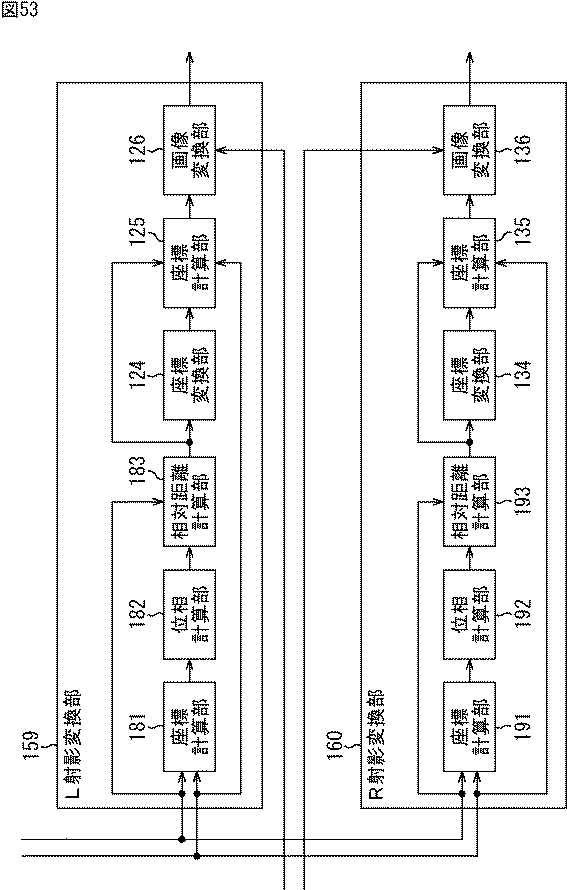
図53は、図33のL射影変換部159とR射影変換部160の構成例を示すブロック図である。
<Configuration Examples of L Projection Conversion Unit and R Projection Conversion Unit>
53 is a block diagram illustrating a configuration example of the L
図53に示す構成のうち、図30の構成と同じ構成には同じ符号を付してある。重複する説明については適宜省略する。 53, the same components as those in FIG. 30 are denoted by the same reference numerals. The overlapping description will be omitted as appropriate.
図53のL射影変換部159の構成は、座標計算部121、位相計算部122、相対距離計算部123の代わりに、座標計算部181、位相計算部182、相対距離計算部183が設けられる点が図30のL射影変換部105の構成と異なる。L射影変換部159は、左目の位置を基準として左目用の画像を射影変換する。
The configuration of the L
具体的には、L射影変換部159の座標計算部181は、図33の座標計算部152と同様に、顔検出部151から供給される左目の位置と、外部から入力される各サブ画素の画面上の座標とに基づいて、各サブ画素の左目の位置を基準としたレンチキュラレンズ109上の座標を計算する。座標計算部181は、計算された各サブ画素の座標を位相計算部182に供給する。
Specifically, the coordinate
位相計算部182は、位相計算部153と同様に、座標計算部181から供給される各サブ画素の座標に基づいて、各サブ画素の左目の位置を基準としたレンチキュラレンズ109上の位相phaselを計算する。位相計算部182は、計算された位相phaselを相対距離計算部183に供給する。
Similarly to the
相対距離計算部183は、位相計算部182から供給される各サブ画素の位相phaselに基づいて、上述した式(14)乃至(16)の視位置(E_x,E_y,E_z)として左目の位置を代入した式により各サブ画素の座標x0´を求め、座標変換部124と座標計算部125に供給する。
Based on the phase phase 1 of each sub-pixel supplied from the
R射影変換部160の構成は、座標計算部131、位相計算部132、相対距離計算部133の代わりに座標計算部191、位相計算部192、相対距離計算部193が設けられる点が、R射影変換部106の構成と異なる。R射影変換部160の座標計算部191、位相計算部192、および相対距離計算部193のそれぞれの処理は、左目の位置の代わりに右目の位置を基準とすることを除いて、L射影変換部159の対応する部の処理と同様であるので、説明は省略する。
The R
<画像処理装置の処理の説明>
図54は、図33の画像処理装置150の表示制御処理を説明するフローチャートである。この表示制御処理は、例えば、左目用の画像と右目用の画像が画像処理装置150に入力されたときに開始される。
<Description of processing of image processing apparatus>
FIG. 54 is a flowchart for explaining display control processing of the
図54のステップS51において、画像処理装置150の顔検出部151は、視聴者を撮像し、視聴者の画像を取得する。ステップS52において、顔検出部151は、視聴者の画像から顔画像を検出し、顔画像から左目の位置と右目の位置を検出する。顔検出部151は、左目の位置を座標計算部152とL射影変換部159に供給し、右目の位置を座標計算部155とR射影変換部160に供給する。
In step S51 of FIG. 54, the face detection unit 151 of the
ステップS53において、座標計算部152は、顔検出部151から供給される左目の位置と、外部から入力される各サブ画素の画面上の座標とに基づいて、各サブ画素の左目の位置を基準としたレンチキュラレンズ109上の座標を計算する。座標計算部152は、計算された各サブ画素の座標を位相計算部153に供給する。
In step S53, the coordinate
ステップS54において、座標計算部155は、顔検出部151から供給される右目の位置と、外部から入力される各サブ画素の画面上の座標とに基づいて、各サブ画素の右目の位置を基準としたレンチキュラレンズ109上の座標を計算する。座標計算部155は、計算された各サブ画素の座標を位相計算部156に供給する。
In step S54, the coordinate
ステップS55において、位相計算部153は、座標計算部152から供給される各サブ画素の座標に基づいて、上述した式(13)により、各サブ画素の左目の位置を基準としたレンチキュラレンズ109上の位相を計算する。位相計算部153は、計算された各サブ画素の位相を面積率計算部154に供給する。
In step S55, the
ステップS56において、位相計算部156は、座標計算部155から供給される各サブ画素の座標に基づいて、上述した式(13)により、各サブ画素の右目の位置を基準としたレンチキュラレンズ109上の位相を計算する。位相計算部156は、計算された各サブ画素の位相を面積率計算部157に供給する。
In step S <b> 56, the
ステップS57において、面積率計算部154は、位相計算部153から供給される各サブ画素の位相に基づいて、各サブ画素における左目で見える領域の面積率area_lを計算し、ブレンド比計算部158に供給する。
In step S57, the area
ステップS58において、面積率計算部157は、位相計算部156から供給される各サブ画素の位相に基づいて、各サブ画素における右目で見える領域の面積率area_rを計算し、ブレンド比計算部158に供給する。
In step S58, the area
ステップS59において、ブレンド比計算部158は、面積率計算部154から供給される各サブ画素における左目で見える領域の面積率area_lと、面積率計算部157から供給される各サブ画素における右目で見える領域の面積率area_rとに基づいて、各サブ画素のブレンド比rate_lとブレンド比rate_rを計算する。ブレンド比計算部158は、ブレンド比rate_lとブレンド比rate_rをブレンド処理部107に供給する。
In step S <b> 59, the blend
ステップS60において、L射影変換部159は、顔検出部151から供給される左目の位置と、外部から入力される各サブ画素の画面上の座標とに基づいて、外部から入力される左目用の画像に対して射影変換処理を行う。この射影変換処理の詳細は、眉間の位置ではなく左目の位置を基準とする点を除いて、図32の射影変換処理と同様であるので、説明は省略する。
In step S60, the L
ステップS61において、R射影変換部160は、顔検出部151から供給される右間の位置と、外部から入力される各サブ画素の画面上の座標とに基づいて、外部から入力される右目用の画像に対して射影変換処理を行う。この射影変換処理の詳細は、眉間の位置ではなく右目の位置を基準とする点を除いて、図32の射影変換処理と同様であるので、説明は省略する。
In step S61, the R-
ステップS62とステップS63の処理は、図31のステップS18とステップS19の処理と同様であるので、説明は省略する。 Since the process of step S62 and step S63 is the same as the process of step S18 and step S19 of FIG. 31, description is abbreviate | omitted.
以上のように、画像処理装置150は、位相phaseLと位相phaseRに基づいて各サブ画素の面積率area_lと面積率area_rを計算し、各サブ画素の面積率area_lと面積率area_rに基づいてサブ画素ごとに左目用の画像と右目用の画像を合成する。従って、重複画素であるサブ画素においてクロストークが目立たず、かつ、重複画素ではないサブ画素のクロストークが増加しない高画質の3D画像を容易に生成し、表示することができる。
As described above, the
また、画像処理装置150は、左目の位置と右目の位置を用いて位相phaseLと位相phaseRを求めるので、視位置が変化する場合であっても、正確に、重複画素において左目用の画像と右目用の画像を合成することができる。
Further, since the
<第3実施の形態>
<画像処理装置の第3実施の形態の構成例>
図55は、本技術を適用した画像処理装置の第3実施の形態の構成例を示すブロック図である。
<Third Embodiment>
<Example of Configuration of Third Embodiment of Image Processing Apparatus>
FIG. 55 is a block diagram illustrating a configuration example of a third embodiment of an image processing device to which the present technology is applied.
図55に示す構成のうち、図33の構成と同じ構成には同じ符号を付してある。重複する説明については適宜省略する。 Of the configurations shown in FIG. 55, configurations the same as the configurations in FIG. 33 are denoted with the same reference numerals. The overlapping description will be omitted as appropriate.
図55の画像処理装置210の構成は、ブレンド比計算部158とブレンド処理部107の代わりにブレンド処理部211が設けられる点が図33の画像処理装置150の構成と異なる。画像処理装置210は、視覚特性を考慮した式により、面積率area_lと面積率area_rとに基づいて左目用の画像と右目用の画像を合成する。
The configuration of the
具体的には、画像処理装置210のブレンド処理部211は、面積率計算部154からの各サブ画素の面積率area_lと面積率計算部157からの各サブ画素の面積率area_rとに基づいて、視覚特性を考慮した式により、L射影変換部159からの左目用の画像と、R射影変換部160からの右目用の画像をサブ画素ごとに合成する。ブレンド処理部211は、各サブ画素の合成後の画像を3D画像として表示部108に供給することにより、3D画像を表示させる。
Specifically, the
<視覚特性を考慮した式の説明>
図56は、表示部108の特性を説明する図である。
<Explanation of formula considering visual characteristics>
FIG. 56 is a diagram for explaining the characteristics of the
図56に示すように、表示部108に入力される3D画像である入力信号Iと、出力される輝度である出力輝度Lの関係は、一般的に、視聴者に視覚される量である主観量Eと入力信号Iの関係が線形となるように設定されている。
As shown in FIG. 56, the relationship between the input signal I, which is a 3D image input to the
具体的には、人間は、明るいほど輝度の変化に鈍感という視覚特性を有するため、図56に示すように、出力輝度Lと主観量Eの関係は、以下の式(39)で近似される。 Specifically, since humans have a visual characteristic that the brighter they are, the less sensitive to changes in luminance, the relationship between the output luminance L and the subjective quantity E is approximated by the following equation (39) as shown in FIG. .
![]()
![]()
なお、式(39)において、bは定数である。 In the formula (39), b is a constant.
また、主観量Eと入力信号Iの関係が線形で表されるためには、以下の式(40)を満たす必要がある。 In addition, in order for the relationship between the subjective quantity E and the input signal I to be expressed linearly, the following formula (40) needs to be satisfied.
![]()
![]()
なお、式(41)において、a,bは定数である。 In the formula (41), a and b are constants.
従って、入力信号Iと出力輝度Lの関係は、以下の式(41)を満たすように設定されている。 Therefore, the relationship between the input signal I and the output luminance L is set so as to satisfy the following formula (41).
![]()
![]()
なお、式(41)において、aは定数である。 In the formula (41), a is a constant.
図57は、図56で示した特性を有する表示部108において表示される、面積率area_lと面積率area_rに基づいて合成された3D画像の主観量Eの例を示す図である。
FIG. 57 is a diagram illustrating an example of the subjective amount E of the 3D image displayed based on the area ratio area_l and the area ratio area_r displayed on the
図57の例では、右目用の画像の全画素の画素値が1(白色)であり、左目用の画像の全画素の画素値が0(黒色)であり、右目で見える領域と左目で見える領域の境界の1つのサブ画素の面積率area_lと面積率area_rが0.5である。 In the example of FIG. 57, the pixel values of all the pixels of the right-eye image are 1 (white), the pixel values of all the pixels of the left-eye image are 0 (black), and are visible to the right eye and the left eye. The area ratio area_l and the area ratio area_r of one sub-pixel at the boundary of the region are 0.5.
この場合、第2実施の形態のように面積率area_lと面積率area_rに基づいて左目用の画像と右目用の画像が合成されると、図57Aに示すように、右目で見える領域と左目で見える領域の境界のサブ画素の画素値が0.5となる。また、そのサブ画素以外の右目で見える領域内のサブ画素の画素値は1であり、左目で見える領域内のサブ画素の画素値は0である。 In this case, when the image for the left eye and the image for the right eye are synthesized based on the area ratio area_l and the area ratio area_r as in the second embodiment, as shown in FIG. The pixel value of the sub pixel at the boundary of the visible area is 0.5. In addition, the pixel value of the sub pixel in the region visible with the right eye other than the sub pixel is 1, and the pixel value of the sub pixel within the region visible with the left eye is 0.
このとき、レンチキュラレンズ109の拡大率Aが2倍であるとすると、右目と左目のそれぞれで見られる画像の画素値は、図57Bに示すようになる。従って、サブ画素当たりの主観量は、視覚特性を考慮しないと、図57Cに示すようになる。即ち、右目のサブ画素当たりの主観量は、1または0.75(=(0.5+1)/2)となり、左目のサブ画素当たりの主観量は、0または0.25(=(0.5+0)/2)となる。
At this time, assuming that the magnification A of the
しかしながら、実際には、視覚特性が存在するため、表示部108において視覚特性が考慮され、図57Dに示すようになる。
However, in reality, since visual characteristics exist, the visual characteristics are taken into consideration in the
即ち、上述した式(40)と(41)により、右目のサブ画素当たりの主観量E0と左目のサブ画素当たりの主観量E1とは、以下の式(42)で表される。 That is, according to the above-described equations (40) and (41), the subjective amount E 0 per sub-pixel of the right eye and the subjective amount E 1 per sub-pixel of the left eye are expressed by the following equation (42).
なお、式(42)において、Iは、各サブ画素の合成後の画像であり、I0,I1は、それぞれ、各サブ画素の右目用の画像、左目用の画像である。また、γは2.2である。 In Expression (42), I is an image after combining the sub-pixels, and I 0 and I 1 are an image for the right eye and an image for the left eye of each sub-pixel, respectively. Γ is 2.2.
図57の例では、面積率area_rと面積率area_lは0.5であるので、上述した式(42)により、境界のサブ画素の主観量E0は約0.80となり、主観量E1は約0.36となる。従って、黒浮きの方が白沈みに比べて大きくなる。 In the example of FIG. 57, since the area ratio area_r and the area ratio area_l are 0.5, the subjective amount E 0 of the boundary sub-pixel is about 0.80 and the subjective amount E 1 is about 0.36 according to the above-described equation (42). . Therefore, the black float is larger than the white sink.
以上のように、第2実施の形態のように面積率area_lと面積率area_rに基づいて視覚特性を考慮せずに左目用の画像と右目用の画像が合成されると、黒浮きと白沈みの程度が異なる。従って、ブレンド処理部211は、視覚特性を考慮した以下の式(43)により、黒浮きと白沈みの程度が同一となるように左目用の画像と右目用の画像を合成する。即ち、ブレンド処理部211は、視覚特性を考慮した式(43)を用いて、テーブルやイタレーションにより、各サブ画素の合成後の画像Iを求める。
As described above, when the image for the left eye and the image for the right eye are synthesized without considering the visual characteristics based on the area ratio area_l and the area ratio area_r as in the second embodiment, The degree of is different. Therefore, the
なお、式(43)において、Iは、各サブ画素の合成後の画像であり、I0,I1は、それぞれ、各サブ画素の右目用の画像、左目用の画像である。また、γは2.2である。 In Expression (43), I is an image after combining the sub-pixels, and I 0 and I 1 are an image for the right eye and an image for the left eye of each sub-pixel, respectively. Γ is 2.2.
図58は、図57の場合に第2実施の形態において合成される画像とブレンド処理部211において合成される画像を説明する図である。
FIG. 58 is a diagram for explaining an image synthesized in the
なお、図58では、サブ画素の右目用の画像I0は1であり、左目用の画像I1は0である。 In FIG 58, the image I 0 for the right eye sub-pixels is 1, the image I 1 for the left eye is 0.
図58に示すように、サブ画素の面積率と、そのサブ画素の合成後の画像の画素値の関係は、第2実施の形態においては線形であり、ブレンド処理部211においては非線形である。
As shown in FIG. 58, the relationship between the area ratio of the sub-pixel and the pixel value of the image after the synthesis of the sub-pixel is linear in the second embodiment and non-linear in the
また、図58に示すように、サブ画素の面積率と、そのサブ画素の主観量の関係は、第2実施の形態においては黒浮きが白沈みに比べて大きくなるが、ブレンド処理部211においては黒浮きと白沈みが同等である。 As shown in FIG. 58, the relationship between the area ratio of the sub-pixel and the subjective amount of the sub-pixel is larger in the black float than in the white sink in the second embodiment. The black float and white sink are equivalent.
<画像処理装置の処理の説明>
図59は、図55の画像処理装置210の表示制御処理を説明するフローチャートである。この表示制御処理は、例えば、左目用の画像と右目用の画像が画像処理装置210に入力されたときに開始される。
<Description of processing of image processing apparatus>
FIG. 59 is a flowchart for explaining display control processing of the
図59のステップS81乃至S90の処理は、図54のステップS51乃至S58、ステップS60、およびステップS61の処理と同様であるので、説明は省略する。 The processes in steps S81 to S90 in FIG. 59 are the same as the processes in steps S51 to S58, step S60, and step S61 in FIG.
ステップS91において、ブレンド処理部211は、面積率計算部154からの各サブ画素の面積率area_lと面積率計算部157からの各サブ画素の面積率area_rとに基づいて、視覚特性を考慮した式(43)により、L射影変換部159からの左目用の画像と、R射影変換部160からの右目用の画像をサブ画素ごとに合成する。具体的には、ブレンド処理部211は、各サブ画素の面積率area_l、面積率area_r、左目用の画像、および右目用の画像に基づいて、サブ画素ごとに、式(43)により合成後の画像Iを求める。
In step S <b> 91, the
ステップS92において、ブレンド処理部211は、各サブ画素の合成後の画像Iを3D画像として表示部108に供給することにより、表示部108に3D画像を表示させる。そして、処理は終了する。
In step S <b> 92, the
以上のように、画像処理装置210は、各サブ画素の面積率area_lと面積率area_rに基づいて、視覚特性を考慮した式により、サブ画素ごとに左目用の画像と右目用の画像を合成する。従って、黒浮きと白沈みの程度が同一になり、クロストークが目立たない高画質の3D画像を容易に生成し、表示することができる。
As described above, the
<第4実施の形態>
<画像処理装置の第4実施の形態の構成例>
図60は、本技術を適用した画像処理装置の第4実施の形態の構成例を示すブロック図である。
<Fourth embodiment>
<Example of Configuration of Fourth Embodiment of Image Processing Apparatus>
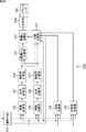
FIG. 60 is a block diagram illustrating a configuration example of the fourth embodiment of an image processing device to which the present technology is applied.
図60に示す構成のうち、図10の構成と同じ構成には同じ符号を付してある。重複する説明については適宜省略する。 In the configuration shown in FIG. 60, the same reference numerals are given to the same configurations as those in FIG. The overlapping description will be omitted as appropriate.
図60の画像処理装置230の構成は、ブレンド比計算部104とブレンド処理部107が設けられず、黒挿入比計算部231、切替処理部232、および黒挿入処理部233が設けられる点が図10の画像処理装置100の構成と異なる。画像処理装置230は、各サブ画素の眉間の位置を基準としたレンチキュラレンズ109上の位相phraseCに基づいて、左目用の画像または右目用の画像に黒画像を合成する。
The configuration of the
具体的には、黒挿入比計算部231は、位相計算部103により計算された各サブ画素の位相phaseCに基づいて、サブ画素ごとに、左目用の画像または右目用の画像に対する黒画像の挿入比(以下、黒挿入比という)を決定し、黒挿入処理部233に供給する。
Specifically, the black insertion ratio calculation unit 231 determines the black image for the left eye image or the right eye image for each sub pixel based on the phase phase C of each sub pixel calculated by the
切替処理部232は、位相計算部103により計算された各サブ画素の位相phaseCに基づいて、サブ画素ごとに、L射影変換部105により射影変換された左目用の画像、または、R射影変換部106により射影変換された右目用の画像を選択する。切替処理部232は、選択された画像を黒挿入処理部233に供給する。
Based on the phase phase C of each sub-pixel calculated by the
黒挿入処理部233は、黒挿入比計算部231から供給される各サブ画素の黒挿入比に基づいて、サブ画素ごとに、切替処理部232から供給される画像と黒画像を合成する。黒挿入処理部233は、黒画像が合成された画像を3D画像としてレンチキュラレンズ109に供給することにより、表示部108に表示させる。
The black
<黒挿入比の例>
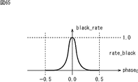
図61は、位相phaseCと黒挿入比の関係の例を示す図である。
<Example of black insertion ratio>
FIG. 61 is a diagram illustrating an example of the relationship between the phase phase C and the black insertion ratio.
図61の例では、黒挿入比black_rateは、例えば、位相phaseCが±0.5と0付近である場合、位相phaseCが±0.5と0に近づくにつれて大きくなり、位相phaseCが±0.5と0付近ではない場合、位相phaseCは0である。 In the example of FIG. 61, the black insertion ratio black_rate, for example, when the phase phase C is around 0 and ± 0.5, become large as the phase phase C approaches zero and ± 0.5, the phase phase C is ± 0.5 around 0 Otherwise, phase phase C is zero.
ここで、上述したように位相が0以下であるサブ画素には、右目用の画像が割り当てられ、位相が0より大きいサブ画素には、左目用の画像が割り当てられる。従って、図61に示した黒挿入比black_rateで黒画像が合成される場合、図62に示すように、位相phaseCが-0.5付近より大きく0付近の負の値より小さいサブ画素の合成後の画像は、右目用の画像となる。また、位相phaseCが0付近の正の値より大きく0.5付近より小さいサブ画素の合成後の画像は、左目用の画像となる。 Here, as described above, a right-eye image is assigned to a sub-pixel having a phase of 0 or less, and a left-eye image is assigned to a sub-pixel having a phase greater than 0. Therefore, when a black image is synthesized with the black insertion ratio black_rate shown in FIG. 61, as shown in FIG. 62, the phase phase C is larger than the vicinity of −0.5 and smaller than the negative value near 0 and after the synthesis of the subpixels. The image is an image for the right eye. In addition, an image after the synthesis of sub-pixels whose phase phase C is greater than a positive value near 0 and smaller than 0.5 is an image for the left eye.
また、位相phaseCが-0.5付近または0付近の負の値であるサブ画素の合成後の画像は、右目用の画像と黒画像が合成された画像となり、位相phaseCが0付近の正の値または0.5付近であるサブ画素の合成後の画像は、左目用の画像と黒画像が合成された画像となる。 Further, the synthesized image of the sub-pixels whose phase phase C is a negative value near −0.5 or near 0 is an image obtained by synthesizing the right-eye image and the black image, and the phase phase C is a positive value near 0. The image after the synthesis of the sub-pixels having a value or near 0.5 is an image in which the image for the left eye and the black image are synthesized.
以上のように、図61の例では、サブ画素の位相phaseCが±0.5付近および0付近である場合、黒挿入比black_rateが0より大きくなるので、サブ画素は、そのサブ画素に割り当てられた左目用の画像または右目用の画像に黒画像が合成された画像となる。ここで、上述したように、重複画素は、位相phaseCが±0.5付近または0付近であるサブ画素である。 As described above, in the example of FIG. 61, when the phase phase C of the sub-pixel is around ± 0.5 and near 0, the black insertion ratio black_rate is greater than 0, so the sub-pixel is assigned to that sub-pixel. This is an image in which a black image is synthesized with an image for the left eye or an image for the right eye. Here, as described above, the overlapping pixels are sub-pixels whose phase phase C is around ± 0.5 or around 0.
従って、図61に示したように黒挿入比が決定され、位相phaseCが±0.5付近および0付近であるサブ画素が、そのサブ画素に割り当てられた左目用の画像または右目用の画像と黒画像が合成された画像となることにより、クロストークが目立たなくなる。 Therefore, as shown in FIG. 61, the black insertion ratio is determined, and the sub-pixels whose phase phase C is around ± 0.5 and near 0 correspond to the left-eye image or right-eye image assigned to the sub-pixel and the black pixel. Since the image becomes a synthesized image, the crosstalk becomes inconspicuous.
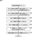
<画像処理装置の処理の説明>
図63は、図60の画像処理装置230の表示制御処理を説明するフローチャートである。この表示制御処理は、例えば、左目用の画像と右目用の画像が画像処理装置230に入力されたときに開始される。
<Description of processing of image processing apparatus>
FIG. 63 is a flowchart for explaining display control processing of the
図63のステップS111乃至S114の処理は、図31のステップS11乃至S14の処理と同様であるので、説明は省略する。 The processes in steps S111 to S114 in FIG. 63 are the same as the processes in steps S11 to S14 in FIG.
ステップS115において、黒挿入比計算部231は、位相計算部103により計算された各サブ画素の位相phaseCに基づいて、各サブ画素の黒挿入比black_rateを決定し、黒挿入処理部233に供給する。
In step S115, the black insertion ratio calculation unit 231 determines the black insertion ratio black_rate of each sub pixel based on the phase phase C of each sub pixel calculated by the
ステップS116およびS117の処理は、図31のステップS16およびS17の処理と同様であるので、説明は省略する。なお、以降のステップS118乃至S120の処理は、サブ画素単位で行われる。 The processing in steps S116 and S117 is the same as the processing in steps S16 and S17 in FIG. Note that the subsequent processing in steps S118 to S120 is performed in units of subpixels.
ステップS118において、切替処理部232は、位相計算部103により計算された処理対象のサブ画素の位相phaseCが0より小さいかどうかを判定する。ステップS118で位相phaseCが0より小さいと判定された場合、切替処理部232は、L射影変換部105により射影変換された処理対象のサブ画素の左目用の画像を選択し、黒挿入処理部233に供給する。
In step S118, the switching
そして、ステップS119において、黒挿入処理部233は、黒挿入比計算部231から供給される処理対象のサブ画素の黒挿入比black_rateに基づいて、切替処理部232から供給される左目用の画像と黒画像を合成する。そして、処理はステップS121に進む。
In step S119, the black
一方、ステップS118で位相phaseCが0より小さくはないと判定された場合、切替処理部232は、R射影変換部106により射影変換された処理対象のサブ画素の右目用の画像を選択し、黒挿入処理部233に供給する。
On the other hand, when it is determined in step S118 that the phase phase C is not smaller than 0, the switching
そして、ステップS120において、黒挿入処理部233は、黒挿入比計算部231から供給される処理対象のサブ画素の黒挿入比black_rateに基づいて、切替処理部232から供給される左目用の画像と黒画像を合成する。そして、処理はステップS121に進む。
In step S120, the black
ステップS121において、黒挿入処理部233は、黒画像が合成された左目用の画像または右目用の画像を3D画像としてレンチキュラレンズ109に供給することにより、表示部108に表示させる。
In step S121, the black
以上のように、画像処理装置230は、各サブ画素のレンチキュラレンズ109上の位相phaseCを計算し、位相phaseCに基づいて、サブ画素ごとに、そのサブ画素に割り当てられた左目用の画像または右目用の画像に黒画像を合成する。従って、画像処理装置100は、左目用の画像が割り当てられる領域と右目用の画像が割り当てられる領域の境界のサブ画素において黒画像を挿入することができる。その結果、左目用の画像と右目用の画像の境界で発生するクロストークが目立たない高画質の3D画像を容易に生成し、表示することができる。
As described above, the
また、画像処理装置210は、眉間の位置を用いて位相phaseCを求めるので、視位置が変化する場合であっても、正確に、左目用の画像と右目用の画像の境界において黒画像を挿入することができる。
In addition, since the
<第5実施の形態>
<画像処理装置の第5実施の形態の構成例>
図64は、本技術を適用した画像処理装置の第5実施の形態の構成例を示すブロック図である。
<Fifth embodiment>
<Example of Configuration of Fifth Embodiment of Image Processing Apparatus>
FIG. 64 is a block diagram illustrating a configuration example of a fifth embodiment of an image processing device to which the present technology is applied.
図64に示す構成のうち、図33および図60の構成と同じ構成には同じ符号を付してある。重複する説明については適宜省略する。 Of the configurations shown in FIG. 64, configurations the same as the configurations in FIGS. 33 and 60 are denoted with the same reference numerals. The overlapping description will be omitted as appropriate.
図64の画像処理装置250の構成は、ブレンド比計算部158とブレンド処理部107の代わりに、黒挿入処理部233、黒挿入比計算部251、および切替処理部252が設けられる点が図33の画像処理装置150の構成と異なる。画像処理装置250は、各サブ画素の面積率area_lと面積率area_rに基づいて、そのサブ画素に割り当てられた左目用の画像または右目用の画像に黒画像を合成する。
The configuration of the
具体的には、黒挿入比計算部251は、面積率計算部154により計算された各サブ画素の面積率area_lと、面積率計算部157により計算された各サブ画素の面積率area_rとに基づいて、各サブ画素の黒挿入比black_rateを決定する。黒挿入比計算部251は、各サブ画素の黒挿入比black_rateを黒挿入処理部233に供給する。
Specifically, the black insertion
切替処理部252は、サブ画素ごとに、面積率計算部154により計算された面積率area_lと、面積率計算部157により計算された面積率area_rのうちの大きい方に対応する、L射影変換部105により射影変換された左目用の画像、または、R射影変換部106により射影変換された右目用の画像を選択する。
For each sub-pixel, the switching
なお、面積率area_lと面積率area_rが同一である場合、切替処理部252は、顔検出部151により検出された左目の位置と右目の位置の中央の位置を眉間の位置として求める。そして、切替処理部252は、その眉間の位置と外部から入力されるサブ画素の画面上の座標とに基づいて、座標計算部102および位相計算部103と同様の処理を行うことにより位相phasecを求め、その位相phasecに基づいて画像を選択する。切替処理部252は、選択された画像を黒挿入処理部233に供給する。
When the area ratio area_l and the area ratio area_r are the same, the switching
<黒挿入比の例>
図65は、面積率area_lおよび面積率area_rと黒挿入比black_rateの関係の例を示す図である。
<Example of black insertion ratio>
FIG. 65 is a diagram illustrating an example of the relationship between the area rate area_l, the area rate area_r, and the black insertion ratio black_rate.
黒挿入比black_rateは、以下の式(44)により決定される。 The black insertion ratio black_rate is determined by the following equation (44).
従って、図66に示すように、位相が0付近である場合にのみ重複画素が発生する場合、図65に示す黒挿入比black_rateが決定され、位相が0付近である場合にのみ、黒画像が挿入される。 Therefore, as shown in FIG. 66, when an overlapping pixel occurs only when the phase is near 0, the black insertion ratio black_rate shown in FIG. 65 is determined, and the black image is displayed only when the phase is near 0. Inserted.
その結果、重複画素においてクロストークが目立たなくなる。また、重複画素ではないサブ画素において黒画像が挿入されることにより輝度が低下することを防止することができる。 As a result, crosstalk becomes inconspicuous in overlapping pixels. Further, it is possible to prevent the luminance from being lowered by inserting a black image in the sub-pixel which is not an overlapping pixel.
<画像処理装置の処理の説明>
図67は、図64の画像処理装置250の表示制御処理を説明するフローチャートである。この表示制御処理は、例えば、左目用の画像と右目用の画像が画像処理装置250に入力されたときに開始される。
<Description of processing of image processing apparatus>
FIG. 67 is a flowchart for explaining display control processing of the
図67のステップS141乃至S148の処理は、図54のステップS51乃至S58の処理と同様であるので、説明は省略する。 The processes in steps S141 to S148 in FIG. 67 are the same as the processes in steps S51 to S58 in FIG.
ステップS149において、黒挿入比計算部251は、面積率計算部154により計算された各サブ画素の面積率area_lと、面積率計算部157により計算された各サブ画素の面積率area_rとに基づいて、サブ画素ごとに、上述した式(44)により、黒挿入比black_rateを決定する。黒挿入比計算部251は、各サブ画素の黒挿入比black_rateを黒挿入処理部233に供給する。
In step S 149, the black insertion
ステップS150およびS151の処理は、図54のステップS60およびS61の処理と同様であるので、説明は省略する。なお、以降のステップS152乃至S156の処理は、サブ画素ごとに行われる。 The processing in steps S150 and S151 is the same as the processing in steps S60 and S61 in FIG. Note that the processing in subsequent steps S152 to S156 is performed for each sub-pixel.
ステップS152において、切替処理部252は、処理対象のサブ画素について、面積率計算部157により計算された右目で見える領域の面積率area_rと面積率計算部154により計算された左目で見える領域の面積率area_lが同一であるかどうかを判定する。ステップS152で面積率area_lと面積率area_rが同一であると判定された場合、処理はステップS153に進む。
In step S152, the switching
ステップS153において、切替処理部252は、顔検出部151から供給される左目の位置および右目の位置と、外部から入力されるサブ画素の画面上の位置とに基づいて位相phasecを求め、その位相phasecが0より小さいかどうかを判定する。
In step S153, the switching
ステップS153で位相phasecが0より小さいと判定された場合、切替処理部252は、R射影変換部106により射影変換された右目用の画像を選択し、黒挿入処理部233に供給する。そして、処理はステップS155に進む。
If it is determined in step S153 that the phase phase c is smaller than 0, the switching
一方、ステップS153で位相phasecが0より小さくないと判定された場合、切替処理部252は、L射影変換部105により射影変換された左目用の画像を選択し、黒挿入処理部233に供給する。そして、処理はステップS156に進む。
On the other hand, when it is determined in step S153 that the phase phase c is not smaller than 0, the switching
また、ステップS152で面積率area_lと面積率area_rが同一ではないと判定された場合、ステップS154において、切替処理部252は、右目で見える領域の面積率area_rが、左目で見える領域の面積率area_lより大きいかどうかを判定する。
If it is determined in step S152 that the area ratio area_l and the area ratio area_r are not the same, in step S154, the switching
ステップS154で面積率area_rが面積率area_lより大きくはないと判定された場合、切替処理部252は、L射影変換部105により射影変換された左目用の画像を選択し、黒挿入処理部233に供給する。そして、処理はステップS156に進む。
If it is determined in step S154 that the area ratio area_r is not greater than the area ratio area_l, the switching
一方、ステップS154で面積率area_rが面積率area_lより大きいと判定された場合、切替処理部252は、R射影変換部106により射影変換された右目用の画像を選択し、黒挿入処理部233に供給する。そして、処理はステップS155に進む。
On the other hand, when it is determined in step S154 that the area ratio area_r is larger than the area ratio area_l, the switching
ステップS155乃至S157の処理は、図63のステップS119乃至S121の処理と同様であるので、説明は省略する。 Since the process of step S155 thru | or S157 is the same as the process of step S119 thru | or S121 of FIG. 63, description is abbreviate | omitted.
以上のように、画像処理装置250は、位相phaseLと位相phaseRに基づいて各サブ画素の面積率area_lと面積率area_rを計算し、各サブ画素の面積率area_lと面積率area_rに基づいてサブ画素ごとに黒画像を挿入する。従って、重複画素であるサブ画素においてクロストークが目立たず、かつ、重複画素ではないサブ画素の輝度が低下しない高画質の3D画像を容易に生成し、表示することができる。
As described above, the
また、画像処理装置250は、左目の位置と右目の位置を用いて位相phaseLと位相phaseRを求めるので、視位置が変化する場合であっても、正確に、重複画素において黒画像を挿入することができる。
Further, since the
<第6実施の形態>
<画像処理装置の第6実施の形態の構成例>
図68は、本技術を適用した画像処理装置の第6実施の形態の構成例を示すブロック図である。
<Sixth embodiment>
<Example of Configuration of Sixth Embodiment of Image Processing Apparatus>
FIG. 68 is a block diagram illustrating a configuration example of a sixth embodiment of an image processing device to which the present technology is applied.
図68に示す構成のうち、図10や図60の構成と同じ構成には同じ符号を付してある。重複する説明については適宜省略する。 68, the same reference numerals are given to the same components as those in FIGS. 10 and 60. The overlapping description will be omitted as appropriate.
図68の画像処理装置270の構成は、黒挿入比計算部231と黒挿入処理部271が新たに設けられる点が図10の画像処理装置100の構成と異なる。
The configuration of the
図68の画像処理装置270は、第1実施の形態と第4実施の形態を組み合わせたものであり、位相phraseCに基づいて左目用の画像と右目用の画像を合成し、合成後の画像に黒画像を合成して3D画像とする。
An
具体的には、黒挿入処理部271は、黒挿入比計算部231から供給される各サブ画素の黒挿入比に基づいて、サブ画素ごとに、ブレンド処理部107により生成される各サブ画素の合成後の画像と黒画像を合成する。黒挿入処理部271は、黒画像が合成された画像を3D画像としてレンチキュラレンズ109に供給することにより、表示部108に表示させる。
Specifically, the black
<画像処理装置の処理の説明>
図69は、図68の画像処理装置270の表示制御処理を説明するフローチャートである。この表示制御処理は、例えば、左目用の画像と右目用の画像が画像処理装置270に入力されたときに開始される。
<Description of processing of image processing apparatus>
FIG. 69 is a flowchart for explaining display control processing of the
図69のステップS171乃至S178の処理は、図31のステップS11乃至S18の処理と同様であるので、説明は省略する。 The processes in steps S171 to S178 in FIG. 69 are the same as the processes in steps S11 to S18 in FIG.
ステップS179において、黒挿入比計算部231は、位相計算部103により計算された各サブ画素の位相phaseCに基づいて、各サブ画素の黒挿入比black_rateを決定し、黒挿入処理部271に供給する。
In step S179, the black insertion ratio calculation unit 231 determines the black insertion ratio black_rate of each sub pixel based on the phase phase C of each sub pixel calculated by the
ステップS180において、黒挿入処理部271は、黒挿入比計算部231から供給される各サブ画素の黒挿入比black_rateに基づいて、サブ画素ごとに、ブレンド処理部107により生成される各サブ画素の合成後の画像と黒画像を合成する。
In step S180, the black
ステップS181において、黒挿入処理部271は、黒画像が合成された画像を3D画像としてレンチキュラレンズ109に供給することにより、3D画像を表示部108に表示させる。
In step S181, the black
<第7実施の形態>
<画像処理装置の第7実施の形態の構成例>
図70は、本技術を適用した画像処理装置の第7実施の形態の構成例を示すブロック図である。
<Seventh embodiment>
<Example of Configuration of Seventh Embodiment of Image Processing Apparatus>
FIG. 70 is a block diagram illustrating a configuration example of the seventh embodiment of an image processing device to which the present technology is applied.
図70に示す構成のうち、図33や図64の構成と同じ構成には同じ符号を付してある。重複する説明については適宜省略する。 Of the configurations shown in FIG. 70, the same reference numerals are given to the same configurations as the configurations of FIG. 33 and FIG. 64. The overlapping description will be omitted as appropriate.
図70の画像処理装置290の構成は、黒挿入比計算部251と黒挿入処理部291が新たに設けられる点が図33の画像処理装置150の構成と異なる。
The configuration of the
図70の画像処理装置290は、第2実施の形態と第5実施の形態を組み合わせたものであり、面積率area_rと面積率area_lに基づいて左目用の画像と右目用の画像を合成し、合成後の画像に黒画像を合成して3D画像とする。
The
具体的には、黒挿入処理部291は、黒挿入比計算部251から供給される各サブ画素の黒挿入比に基づいて、サブ画素ごとに、ブレンド処理部107により生成される各サブ画素の合成後の画像と黒画像を合成する。黒挿入処理部291は、黒画像が合成された画像を3D画像としてレンチキュラレンズ109に供給することにより、表示部108に表示させる。
Specifically, the black
<画像処理装置の処理の説明>
図71は、図70の画像処理装置290の表示制御処理を説明するフローチャートである。この表示制御処理は、例えば、左目用の画像と右目用の画像が画像処理装置290に入力されたときに開始される。
<Description of processing of image processing apparatus>
71 is a flowchart for explaining display control processing of the
図71のステップS201乃至S212の処理は、図54のステップS51乃至S62の処理と同様であるので、説明は省略する。 71 are the same as the processes in steps S51 to S62 in FIG. 54, and thus the description thereof is omitted.
ステップS213において、黒挿入比計算部251は、面積率計算部154により計算された各サブ画素の面積率area_lと、面積率計算部157により計算された各サブ画素の面積率area_rとに基づいて、サブ画素ごとに、上述した式(44)により、黒挿入比black_rateを決定する。黒挿入比計算部251は、黒挿入比black_rateを黒挿入処理部291に供給する。
In step S213, the black insertion
ステップS214において、黒挿入処理部291は、黒挿入比計算部251から供給される各サブ画素の黒挿入比black_rateに基づいて、サブ画素ごとに、ブレンド処理部107により生成される各サブ画素の合成後の画像と黒画像を合成する。
In step S214, the black
ステップS215において、黒挿入処理部291は、黒画像が合成された画像を3D画像としてレンチキュラレンズ109に供給することにより、3D画像を表示部108に表示させる。
In step S215, the black
<第8実施の形態>
<画像処理装置の第8実施の形態の構成例>
図72は、本技術を適用した画像処理装置の第8実施の形態の構成例を示すブロック図である。
<Eighth embodiment>
<Example of Configuration of Eighth Embodiment of Image Processing Apparatus>
FIG. 72 is a block diagram illustrating a configuration example of an eighth embodiment of an image processing device to which the present technology is applied.
図72に示す構成のうち、図55、図64、および図70の構成と同じ構成には同じ符号を付してある。重複する説明については適宜省略する。 Of the configurations shown in FIG. 72, configurations the same as the configurations in FIG. 55, FIG. 64, and FIG. The overlapping description will be omitted as appropriate.
図72の画像処理装置310の構成は、黒挿入比計算部251と黒挿入処理部291が新たに設けられる点が図55の画像処理装置210の構成と異なる。
The configuration of the
図72の画像処理装置310は、第3実施の形態と第5実施の形態を組み合わせたものであり、面積率area_rと面積率area_lに基づいて、視覚特性を考慮した式(43)により左目用の画像と右目用の画像を合成し、合成後の画像に黒画像を合成して3D画像とする。
The
<画像処理装置の処理の説明>
図73は、図72の画像処理装置310の表示制御処理を説明するフローチャートである。この表示制御処理は、例えば、左目用の画像と右目用の画像が画像処理装置310に入力されたときに開始される。
<Description of processing of image processing apparatus>
FIG. 73 is a flowchart for explaining display control processing of the
図73のステップS231乃至S241の処理は、図59のステップS81乃至S91の処理と同様であるので、説明は省略する。また、ステップS242乃至S244の処理は、図71のステップS213乃至S215の処理と同様であるので、説明は省略する。 73 are the same as the processes in steps S81 to S91 in FIG. 59, and thus the description thereof is omitted. Also, the processing in steps S242 through S244 is the same as the processing in steps S213 through S215 in FIG.
<第9実施の形態>
<本技術を適用したコンピュータの説明>
上述した一連の処理は、ハードウエアにより実行することもできるし、ソフトウエアにより実行することもできる。一連の処理をソフトウエアにより実行する場合には、そのソフトウエアを構成するプログラムが、コンピュータにインストールされる。ここで、コンピュータには、専用のハードウエアに組み込まれているコンピュータや、各種のプログラムをインストールすることで、各種の機能を実行することが可能な、例えば汎用のパーソナルコンピュータなどが含まれる。
<Ninth Embodiment>
<Description of computer to which this technology is applied>
The series of processes described above can be executed by hardware or can be executed by software. When a series of processing is executed by software, a program constituting the software is installed in the computer. Here, the computer includes, for example, a general-purpose personal computer capable of executing various functions by installing various programs by installing a computer incorporated in dedicated hardware.
図74は、上述した一連の処理をプログラムにより実行するコンピュータのハードウエアの構成例を示すブロック図である。 FIG. 74 is a block diagram showing an example of the hardware configuration of a computer that executes the above-described series of processing by a program.
コンピュータにおいて、CPU(Central Processing Unit)401,ROM(Read Only Memory)402,RAM(Random Access Memory)403は、バス404により相互に接続されている。
In a computer, a CPU (Central Processing Unit) 401, a ROM (Read Only Memory) 402, and a RAM (Random Access Memory) 403 are connected to each other by a
バス404には、さらに、入出力インタフェース405が接続されている。入出力インタフェース405には、入力部406、出力部407、記憶部408、通信部409、及びドライブ410が接続されている。
An input /
入力部406は、キーボード、マウス、マイクロフォンなどよりなる。出力部407は、ディスプレイ、スピーカなどよりなる。記憶部408は、ハードディスクや不揮発性のメモリなどよりなる。通信部409は、ネットワークインタフェースなどよりなる。ドライブ410は、磁気ディスク、光ディスク、光磁気ディスク、又は半導体メモリなどのリムーバブルメディア411を駆動する。
The
以上のように構成されるコンピュータでは、CPU401が、例えば、記憶部408に記憶されているプログラムを、入出力インタフェース405及びバス404を介して、RAM403にロードして実行することにより、上述した一連の処理が行われる。
In the computer configured as described above, the
コンピュータ(CPU401)が実行するプログラムは、例えば、パッケージメディア等としてのリムーバブルメディア411に記録して提供することができる。また、プログラムは、ローカルエリアネットワーク、インターネット、デジタル衛星放送といった、有線または無線の伝送媒体を介して提供することができる。
The program executed by the computer (CPU 401) can be provided by being recorded on a
コンピュータでは、プログラムは、リムーバブルメディア411をドライブ410に装着することにより、入出力インタフェース405を介して、記憶部408にインストールすることができる。また、プログラムは、有線または無線の伝送媒体を介して、通信部409で受信し、記憶部408にインストールすることができる。その他、プログラムは、ROM402や記憶部408に、あらかじめインストールしておくことができる。
In the computer, the program can be installed in the
なお、コンピュータが実行するプログラムは、本明細書で説明する順序に沿って時系列に処理が行われるプログラムであっても良いし、並列に、あるいは呼び出しが行われたとき等の必要なタイミングで処理が行われるプログラムであっても良い。 The program executed by the computer may be a program that is processed in time series in the order described in this specification, or in parallel or at a necessary timing such as when a call is made. It may be a program for processing.
また、本技術の実施の形態は、上述した実施の形態に限定されるものではなく、本技術の要旨を逸脱しない範囲において種々の変更が可能である。 The embodiments of the present technology are not limited to the above-described embodiments, and various modifications can be made without departing from the gist of the present technology.
例えば、本技術は、バリア式表示装置にも適用することができる。この場合、拡大率Aが1とされ、レンチキュラレンズが遮光部としての遮光バリアに置き換えられる。 For example, the present technology can be applied to a barrier display device. In this case, the enlargement ratio A is set to 1, and the lenticular lens is replaced with a light shielding barrier as a light shielding portion.
また、例えば、本技術は、1つの機能をネットワークを介して複数の装置で分担、共同して処理するクラウドコンピューティングの構成をとることができる。 Further, for example, the present technology can take a configuration of cloud computing in which one function is shared by a plurality of devices via a network and is jointly processed.
また、上述のフローチャートで説明した各ステップは、1つの装置で実行する他、複数の装置で分担して実行することができる。 In addition, each step described in the above flowchart can be executed by being shared by a plurality of apparatuses in addition to being executed by one apparatus.
さらに、1つのステップに複数の処理が含まれる場合には、その1つのステップに含まれる複数の処理は、1つの装置で実行する他、複数の装置で分担して実行することができる。 Further, when a plurality of processes are included in one step, the plurality of processes included in the one step can be executed by being shared by a plurality of apparatuses in addition to being executed by one apparatus.
なお、本技術は、以下のような構成もとることができる。 In addition, this technique can also take the following structures.
(1)
表示部に表示される3D画像の左目で見える領域と右目で見える領域を限定する遮光部上の前記3D画像の各画素の位相を計算する位相計算部と、
前記位相計算部により計算された前記位相に基づいて、前記画素ごとに、前記3D画像を構成する左目用の画像と右目用の画像を合成するブレンド処理部と
を備える画像処理装置。
(2)
前記位相計算部により計算された前記位相に基づいて、前記3D画像の各画素における前記左目で見える領域と前記右目で見える領域の面積率を計算する面積率計算部
をさらに備え、
前記ブレンド処理部は、前記面積率計算部により計算された前記面積率に基づいて、前記画素ごとに、前記左目用の画像と前記右目用の画像を合成する
前記(1)に記載の画像処理装置。
(3)
前記ブレンド処理部は、前記面積率計算部により計算された前記面積率に基づいて、視覚特性を考慮した式により、前記画素ごとに、前記左目用の画像と前記右目用の画像を合成する
前記(2)に記載の画像処理装置。
(4)
前記位相計算部は、視位置に基づいて前記位相を計算する
前記(1)乃至(3)のいずれかに記載の画像処理装置。
(5)
前記位相計算部は、前記表示部の画面に垂直な方向の前記遮光部の位置が、前記表示部の画面に水平な方向の位置に応じて異なることを考慮した式により、前記視位置に基づいて前記位相を計算する
前記(4)に記載の画像処理装置。
(6)
前記位相計算部は、前記表示部からの光が前記遮光部で屈折することを考慮した式により、前記視位置に基づいて前記位相を計算する
前記(4)または(5)に記載の画像処理装置。
(7)
前記視位置に基づいて前記左目用の画像と前記右目用の画像を射影変換する射影変換部
をさらに備え、
前記ブレンド処理部は、前記射影変換部により射影変換された前記左目用の画像と前記右目用の画像を合成する
前記(1)乃至(7)のいずれかに記載の画像処理装置。
(8)
前記位相計算部により計算された前記位相に基づいて、前記ブレンド処理部による合成の結果得られる画像に黒画像を合成する黒挿入処理部
をさらに備える
前記(1)乃至(7)のいずれかに記載の画像処理装置。
(9)
画像処理装置が、
表示部に表示される3D画像の左目で見える領域と右目で見える領域を限定する遮光部上の前記3D画像の各画素の位相を計算する位相計算ステップと、
前記位相計算ステップの処理により計算された前記位相に基づいて、前記画素ごとに、前記3D画像を構成する左目用の画像と右目用の画像を合成するブレンド処理ステップと
を含む画像処理方法。
(10)
コンピュータを、
表示部に表示される3D画像の左目で見える領域と右目で見える領域を限定する遮光部上の前記3D画像の各画素の位相を計算する位相計算部と、
前記位相計算部により計算された前記位相に基づいて、前記画素ごとに、前記3D画像を構成する左目用の画像と右目用の画像を合成するブレンド処理部と
して機能させるためのプログラム。
(1)
A phase calculation unit that calculates a phase of each pixel of the 3D image on the light-shielding unit that limits a region that can be seen by the left eye and a region that can be seen by the right eye of the 3D image displayed on the display unit;
An image processing apparatus comprising: a blend processing unit that synthesizes a left-eye image and a right-eye image constituting the 3D image for each pixel based on the phase calculated by the phase calculation unit.
(2)
Based on the phase calculated by the phase calculation unit, an area ratio calculation unit that calculates an area ratio of the region seen by the left eye and the region seen by the right eye in each pixel of the 3D image,
The image processing according to (1), wherein the blend processing unit synthesizes the left-eye image and the right-eye image for each pixel based on the area ratio calculated by the area-ratio calculation unit. apparatus.
(3)
The blend processing unit synthesizes the image for the left eye and the image for the right eye for each of the pixels based on the area ratio calculated by the area ratio calculation unit, using an expression that considers visual characteristics. The image processing apparatus according to (2).
(4)
The image processing device according to any one of (1) to (3), wherein the phase calculation unit calculates the phase based on a visual position.
(5)
The phase calculation unit is based on the viewing position according to an expression that takes into account that the position of the light shielding unit in a direction perpendicular to the screen of the display unit differs depending on the position in a direction horizontal to the screen of the display unit. The image processing apparatus according to (4), wherein the phase is calculated.
(6)
The image processing according to (4) or (5), wherein the phase calculation unit calculates the phase based on the viewing position using an expression that takes into account that light from the display unit is refracted by the light shielding unit. apparatus.
(7)
A projection conversion unit that performs projective conversion of the image for the left eye and the image for the right eye based on the viewing position;
The image processing apparatus according to any one of (1) to (7), wherein the blend processing unit synthesizes the image for the left eye and the image for the right eye that have undergone projective conversion by the projective conversion unit.
(8)
A black insertion processing unit that combines a black image with an image obtained as a result of combining by the blend processing unit based on the phase calculated by the phase calculation unit. The image processing apparatus described.
(9)
The image processing device
A phase calculation step of calculating a phase of each pixel of the 3D image on the light-shielding unit that limits a region visible to the left eye and a region visible to the right eye of the 3D image displayed on the display unit;
An image processing method including: a blend processing step of combining, for each pixel, a left-eye image and a right-eye image that constitute the 3D image based on the phase calculated by the phase calculation step.
(10)
Computer
A phase calculation unit that calculates a phase of each pixel of the 3D image on the light-shielding unit that limits a region that can be seen by the left eye and a region that can be seen by the right eye of the 3D image displayed on the display unit;
A program for causing each pixel to function as a blend processing unit that synthesizes a left-eye image and a right-eye image that constitute the 3D image based on the phase calculated by the phase calculation unit.
100 画像処理装置, 103 位相計算部, 107 ブレンド処理部, 105 L射影変換部, 106 R射影変換部, 108 表示部, 109 レンチキュラレンズ, 150 画像処理装置, 153 位相計算部, 154 面積率計算部, 156 位相計算部, 157 面積率計算部, 159 L射影変換部, 160 R射影変換部, 210 画像処理装置, 211 ブレンド処理部, 230 画像処理装置, 233 黒挿入処理部, 250 画像処理装置, 270 画像処理装置, 271 黒挿入処理部, 290 画像処理装置, 291 黒挿入処理部, 310 画像処理装置
DESCRIPTION OF
Claims (10)
前記位相計算部により計算された前記位相に基づいて、前記画素ごとに、前記3D画像を構成する左目用の画像と右目用の画像を合成するブレンド処理部と
を備える画像処理装置。 A phase calculation unit that calculates a phase of each pixel of the 3D image on the light-shielding unit that limits a region that can be seen by the left eye and a region that can be seen by the right eye of the 3D image displayed on the display unit;
An image processing apparatus comprising: a blend processing unit that synthesizes a left-eye image and a right-eye image constituting the 3D image for each pixel based on the phase calculated by the phase calculation unit.
をさらに備え、
前記ブレンド処理部は、前記面積率計算部により計算された前記面積率に基づいて、前記画素ごとに、前記左目用の画像と前記右目用の画像を合成する
請求項1に記載の画像処理装置。 Based on the phase calculated by the phase calculation unit, an area ratio calculation unit that calculates an area ratio of the region seen by the left eye and the region seen by the right eye in each pixel of the 3D image,
The image processing apparatus according to claim 1, wherein the blend processing unit synthesizes the image for the left eye and the image for the right eye for each pixel based on the area ratio calculated by the area ratio calculation unit. .
請求項2に記載の画像処理装置。 The blend processing unit synthesizes the image for the left eye and the image for the right eye for each of the pixels based on the area ratio calculated by the area ratio calculation unit, using an expression that considers visual characteristics. Item 3. The image processing apparatus according to Item 2.
請求項1に記載の画像処理装置。 The image processing device according to claim 1, wherein the phase calculation unit calculates the phase based on a visual position.
請求項4に記載の画像処理装置。 The phase calculation unit is based on the viewing position according to an expression that takes into account that the position of the light shielding unit in a direction perpendicular to the screen of the display unit differs depending on the position in a direction horizontal to the screen of the display unit. The image processing apparatus according to claim 4, wherein the phase is calculated.
請求項4に記載の画像処理装置。 The image processing apparatus according to claim 4, wherein the phase calculation unit calculates the phase based on the viewing position using an expression that considers that light from the display unit is refracted by the light shielding unit.
をさらに備え、
前記ブレンド処理部は、前記射影変換部により射影変換された前記左目用の画像と前記右目用の画像を合成する
請求項1に記載の画像処理装置。 A projection conversion unit that performs projective conversion of the image for the left eye and the image for the right eye based on the viewing position;
The image processing apparatus according to claim 1, wherein the blend processing unit synthesizes the image for the left eye and the image for the right eye that have undergone projective conversion by the projective conversion unit.
をさらに備える
請求項1に記載の画像処理装置。 The image processing apparatus according to claim 1, further comprising: a black insertion processing unit configured to combine a black image with an image obtained as a result of combining by the blend processing unit based on the phase calculated by the phase calculation unit.
表示部に表示される3D画像の左目で見える領域と右目で見える領域を限定する遮光部上の前記3D画像の各画素の位相を計算する位相計算ステップと、
前記位相計算ステップの処理により計算された前記位相に基づいて、前記画素ごとに、前記3D画像を構成する左目用の画像と右目用の画像を合成するブレンド処理ステップと
を含む画像処理方法。 The image processing device
A phase calculation step of calculating a phase of each pixel of the 3D image on the light-shielding unit that limits a region visible to the left eye and a region visible to the right eye of the 3D image displayed on the display unit;
An image processing method including: a blend processing step of combining, for each pixel, a left-eye image and a right-eye image that constitute the 3D image based on the phase calculated by the phase calculation step.
表示部に表示される3D画像の左目で見える領域と右目で見える領域を限定する遮光部上の前記3D画像の各画素の位相を計算する位相計算部と、
前記位相計算部により計算された前記位相に基づいて、前記画素ごとに、前記3D画像を構成する左目用の画像と右目用の画像を合成するブレンド処理部と
して機能させるためのプログラム。 Computer
A phase calculation unit that calculates a phase of each pixel of the 3D image on the light-shielding unit that limits a region that can be seen by the left eye and a region that can be seen by the right eye of the 3D image displayed on the display unit;
A program for causing each pixel to function as a blend processing unit that synthesizes a left-eye image and a right-eye image that constitute the 3D image based on the phase calculated by the phase calculation unit.
Priority Applications (3)
| Application Number | Priority Date | Filing Date | Title |
|---|---|---|---|
| JP2012264772A JP2014110568A (en) | 2012-12-03 | 2012-12-03 | Image processing device, image processing method, and program |
| US14/054,951 US9282322B2 (en) | 2012-12-03 | 2013-10-16 | Image processing device, image processing method, and program |
| CN201310608509.XA CN103856769B (en) | 2012-12-03 | 2013-11-26 | Image processing device and image processing method |
Applications Claiming Priority (1)
| Application Number | Priority Date | Filing Date | Title |
|---|---|---|---|
| JP2012264772A JP2014110568A (en) | 2012-12-03 | 2012-12-03 | Image processing device, image processing method, and program |
Publications (1)
| Publication Number | Publication Date |
|---|---|
| JP2014110568A true JP2014110568A (en) | 2014-06-12 |
Family
ID=50825004
Family Applications (1)
| Application Number | Title | Priority Date | Filing Date |
|---|---|---|---|
| JP2012264772A Pending JP2014110568A (en) | 2012-12-03 | 2012-12-03 | Image processing device, image processing method, and program |
Country Status (3)
| Country | Link |
|---|---|
| US (1) | US9282322B2 (en) |
| JP (1) | JP2014110568A (en) |
| CN (1) | CN103856769B (en) |
Cited By (4)
| Publication number | Priority date | Publication date | Assignee | Title |
|---|---|---|---|---|
| WO2019160160A1 (en) * | 2018-02-19 | 2019-08-22 | 京セラ株式会社 | Head-up display, head-up display system, and moving body |
| WO2020004275A1 (en) * | 2018-06-26 | 2020-01-02 | 京セラ株式会社 | Three-dimensional display device, control controller, three-dimensional display method, three-dimensional display system, and moving body |
| WO2020256154A1 (en) * | 2019-06-21 | 2020-12-24 | 京セラ株式会社 | Three-dimensional display device, three-dimensional display system, and moving object |
| JP2021522545A (en) * | 2018-04-24 | 2021-08-30 | アリオスコピーAlioscopy | A system and method for displaying an automatic stereoscopic image with N viewpoints on a mobile display. |
Families Citing this family (5)
| Publication number | Priority date | Publication date | Assignee | Title |
|---|---|---|---|---|
| US10182224B2 (en) * | 2015-08-31 | 2019-01-15 | Theia Limited | Method for creating 3D image |
| WO2018061706A1 (en) * | 2016-09-28 | 2018-04-05 | 富士フイルム株式会社 | Lenticular display body, method for forming lenticular image, method for manufacturing lenticular display body, and program for forming lenticular image |
| DE102019111467A1 (en) * | 2019-05-03 | 2020-11-05 | Carl Zeiss Jena Gmbh | Display device and method for the simultaneous display of different images in at least two eyes |
| US20230291888A1 (en) * | 2020-07-22 | 2023-09-14 | Kyocera Corporation | Three-dimensional display device, head-up display, and movable body |
| CN112801920B (en) * | 2021-03-30 | 2022-05-27 | 深圳市立体通科技有限公司 | Three-dimensional image crosstalk optimization method and device, storage medium and electronic equipment |
Family Cites Families (16)
| Publication number | Priority date | Publication date | Assignee | Title |
|---|---|---|---|---|
| JPH0340692A (en) | 1989-07-07 | 1991-02-21 | Nippon Telegr & Teleph Corp <Ntt> | Stereoscopic picture display method |
| GB9715397D0 (en) * | 1997-07-23 | 1997-09-24 | Philips Electronics Nv | Lenticular screen adaptor |
| JP2003107392A (en) | 2001-09-28 | 2003-04-09 | Sanyo Electric Co Ltd | Stereoscopic video image display device of head position tacking type |
| GB2406730A (en) * | 2003-09-30 | 2005-04-06 | Ocuity Ltd | Directional display. |
| KR100781278B1 (en) * | 2006-05-04 | 2007-11-30 | 엘지전자 주식회사 | Apparatus for Displaying 3D Image |
| DE102006031799B3 (en) * | 2006-07-06 | 2008-01-31 | Fraunhofer-Gesellschaft zur Förderung der angewandten Forschung e.V. | Method for autostereoscopic display of image information with adaptation to changes in the head position of the viewer |
| JP4591591B2 (en) * | 2008-07-28 | 2010-12-01 | ソニー株式会社 | Stereoscopic image display device and manufacturing method thereof |
| CN102725789B (en) * | 2009-12-04 | 2015-08-05 | Nlt科技股份有限公司 | 3 d display device, method for generation of the view data for stereo display |
| JP5364666B2 (en) * | 2010-09-13 | 2013-12-11 | 株式会社東芝 | Stereoscopic image display apparatus, method and program |
| KR20120109158A (en) * | 2011-03-28 | 2012-10-08 | 삼성디스플레이 주식회사 | Display system |
| JP6050941B2 (en) * | 2011-05-26 | 2016-12-21 | サターン ライセンシング エルエルシーSaturn Licensing LLC | Display device and method, and program |
| JP5715539B2 (en) * | 2011-10-06 | 2015-05-07 | 株式会社ジャパンディスプレイ | Display device and electronic device |
| TW201320717A (en) * | 2011-11-08 | 2013-05-16 | Unique Instr Co Ltd | Method of displaying 3D image |
| US20140340746A1 (en) * | 2011-12-19 | 2014-11-20 | Panasonic Intellectual Property Corporation Of America | Display device |
| WO2013099270A1 (en) * | 2011-12-28 | 2013-07-04 | パナソニック株式会社 | Light source control device and image display device |
| KR20140046563A (en) * | 2012-10-05 | 2014-04-21 | 삼성전자주식회사 | Image processing apparatus and method for performing image rendering based on direction of display |
-
2012
- 2012-12-03 JP JP2012264772A patent/JP2014110568A/en active Pending
-
2013
- 2013-10-16 US US14/054,951 patent/US9282322B2/en not_active Expired - Fee Related
- 2013-11-26 CN CN201310608509.XA patent/CN103856769B/en not_active Expired - Fee Related
Cited By (11)
| Publication number | Priority date | Publication date | Assignee | Title |
|---|---|---|---|---|
| WO2019160160A1 (en) * | 2018-02-19 | 2019-08-22 | 京セラ株式会社 | Head-up display, head-up display system, and moving body |
| JP2019145967A (en) * | 2018-02-19 | 2019-08-29 | 京セラ株式会社 | Head-up display, head-up display system, and mobile body |
| JP7129789B2 (en) | 2018-02-19 | 2022-09-02 | 京セラ株式会社 | Head-up displays, head-up display systems, and moving objects |
| JP2021522545A (en) * | 2018-04-24 | 2021-08-30 | アリオスコピーAlioscopy | A system and method for displaying an automatic stereoscopic image with N viewpoints on a mobile display. |
| WO2020004275A1 (en) * | 2018-06-26 | 2020-01-02 | 京セラ株式会社 | Three-dimensional display device, control controller, three-dimensional display method, three-dimensional display system, and moving body |
| JPWO2020004275A1 (en) * | 2018-06-26 | 2021-07-08 | 京セラ株式会社 | 3D display device, control controller, 3D display method, 3D display system, and mobile |
| JP7145214B2 (en) | 2018-06-26 | 2022-09-30 | 京セラ株式会社 | 3D DISPLAY DEVICE, CONTROLLER, 3D DISPLAY METHOD, 3D DISPLAY SYSTEM, AND MOVING OBJECT |
| US11924400B2 (en) | 2018-06-26 | 2024-03-05 | Kyocera Corporation | Three-dimensional display device, control controller, three-dimensional display method, three-dimensional display system, and moving body |
| WO2020256154A1 (en) * | 2019-06-21 | 2020-12-24 | 京セラ株式会社 | Three-dimensional display device, three-dimensional display system, and moving object |
| JPWO2020256154A1 (en) * | 2019-06-21 | 2020-12-24 | ||
| JP7337158B2 (en) | 2019-06-21 | 2023-09-01 | 京セラ株式会社 | 3D display device, 3D display system, and moving object |
Also Published As
| Publication number | Publication date |
|---|---|
| US20140152663A1 (en) | 2014-06-05 |
| CN103856769B (en) | 2017-04-12 |
| US9282322B2 (en) | 2016-03-08 |
| CN103856769A (en) | 2014-06-11 |
Similar Documents
| Publication | Publication Date | Title |
|---|---|---|
| JP2014110568A (en) | Image processing device, image processing method, and program | |
| US10567741B2 (en) | Stereoscopic image display device, terminal device, stereoscopic image display method, and program thereof | |
| US10237541B2 (en) | Stereoscopic image display device, image processing device, and stereoscopic image processing method with reduced 3D moire | |
| CN113170136A (en) | Motion smoothing of reprojected frames | |
| JP5809293B2 (en) | Display device | |
| JP5372203B2 (en) | Multi-scene 3D image display method | |
| KR102121389B1 (en) | Glassless 3d display apparatus and contorl method thereof | |
| JP6452579B2 (en) | Wide viewing angle autostereoscopic image display method and display device | |
| JP5881732B2 (en) | Image processing apparatus, stereoscopic image display apparatus, image processing method, and image processing program | |
| WO2012157540A1 (en) | Image processing apparatus, image processing method, and program | |
| KR20140089860A (en) | Display apparatus and display method thereof | |
| KR20120075829A (en) | Apparatus and method for rendering subpixel adaptively | |
| JP4856534B2 (en) | Image generating apparatus, program, and information storage medium | |
| JP2012186653A (en) | Image display apparatus, method, and program | |
| JP2006287592A (en) | Image generating device, electronic equipment, and image generation method and program | |
| KR101975246B1 (en) | Multi view image display apparatus and contorl method thereof | |
| JPWO2019229906A1 (en) | Image display system | |
| JP5763208B2 (en) | Stereoscopic image display apparatus, image processing apparatus, and image processing method | |
| US20140198104A1 (en) | Stereoscopic image generating method, stereoscopic image generating device, and display device having same | |
| WO2014119555A1 (en) | Image processing device, display device and program | |
| JP2014006674A (en) | Image processing device, control method of the same and program | |
| CN111919437B (en) | Stereoscopic knitting for head tracking autostereoscopic displays | |
| JP4695470B2 (en) | Image generating apparatus, image generating method, and program | |
| JP2008058584A (en) | Three-dimensional image display method and three-dimensional image display device | |
| WO2023153141A1 (en) | Information processing device, information processing method, and computer-readable recording medium |