JP2014106980A - Apparatus and method for segmenting contour in image based on user interaction - Google Patents
Apparatus and method for segmenting contour in image based on user interaction Download PDFInfo
- Publication number
- JP2014106980A JP2014106980A JP2013245211A JP2013245211A JP2014106980A JP 2014106980 A JP2014106980 A JP 2014106980A JP 2013245211 A JP2013245211 A JP 2013245211A JP 2013245211 A JP2013245211 A JP 2013245211A JP 2014106980 A JP2014106980 A JP 2014106980A
- Authority
- JP
- Japan
- Prior art keywords
- contour
- interface
- user
- mode
- correcting
- Prior art date
- Legal status (The legal status is an assumption and is not a legal conclusion. Google has not performed a legal analysis and makes no representation as to the accuracy of the status listed.)
- Pending
Links
- 238000000034 method Methods 0.000 title claims abstract description 32
- 230000003993 interaction Effects 0.000 title abstract description 5
- 238000012937 correction Methods 0.000 claims description 76
- 230000036961 partial effect Effects 0.000 claims description 18
- 230000009471 action Effects 0.000 claims description 9
- 238000004091 panning Methods 0.000 claims description 9
- 238000003825 pressing Methods 0.000 claims description 9
- 230000003247 decreasing effect Effects 0.000 claims description 7
- 230000002829 reductive effect Effects 0.000 claims description 6
- 230000033001 locomotion Effects 0.000 claims 5
- 230000011218 segmentation Effects 0.000 abstract description 7
- 238000012986 modification Methods 0.000 abstract description 2
- 230000004048 modification Effects 0.000 abstract description 2
- 238000012545 processing Methods 0.000 description 27
- 230000008859 change Effects 0.000 description 12
- 238000004195 computer-aided diagnosis Methods 0.000 description 9
- 238000003745 diagnosis Methods 0.000 description 7
- 238000010586 diagram Methods 0.000 description 6
- 238000013500 data storage Methods 0.000 description 3
- 230000006870 function Effects 0.000 description 3
- 230000003902 lesion Effects 0.000 description 3
- 230000008569 process Effects 0.000 description 3
- 238000000638 solvent extraction Methods 0.000 description 3
- 238000004891 communication Methods 0.000 description 2
- 230000003211 malignant effect Effects 0.000 description 2
- 241000282320 Panthera leo Species 0.000 description 1
- 238000003491 array Methods 0.000 description 1
- 238000004590 computer program Methods 0.000 description 1
- 239000011521 glass Substances 0.000 description 1
- 230000002452 interceptive effect Effects 0.000 description 1
- 230000000670 limiting effect Effects 0.000 description 1
- 230000003287 optical effect Effects 0.000 description 1
- 230000000644 propagated effect Effects 0.000 description 1
- 230000009467 reduction Effects 0.000 description 1
- 239000007787 solid Substances 0.000 description 1
Images


Classifications
-
- G—PHYSICS
- G06—COMPUTING; CALCULATING OR COUNTING
- G06T—IMAGE DATA PROCESSING OR GENERATION, IN GENERAL
- G06T7/00—Image analysis
- G06T7/10—Segmentation; Edge detection
- G06T7/12—Edge-based segmentation
-
- A—HUMAN NECESSITIES
- A61—MEDICAL OR VETERINARY SCIENCE; HYGIENE
- A61B—DIAGNOSIS; SURGERY; IDENTIFICATION
- A61B6/00—Apparatus or devices for radiation diagnosis; Apparatus or devices for radiation diagnosis combined with radiation therapy equipment
- A61B6/46—Arrangements for interfacing with the operator or the patient
- A61B6/467—Arrangements for interfacing with the operator or the patient characterised by special input means
- A61B6/469—Arrangements for interfacing with the operator or the patient characterised by special input means for selecting a region of interest [ROI]
-
- G—PHYSICS
- G06—COMPUTING; CALCULATING OR COUNTING
- G06F—ELECTRIC DIGITAL DATA PROCESSING
- G06F3/00—Input arrangements for transferring data to be processed into a form capable of being handled by the computer; Output arrangements for transferring data from processing unit to output unit, e.g. interface arrangements
- G06F3/01—Input arrangements or combined input and output arrangements for interaction between user and computer
- G06F3/048—Interaction techniques based on graphical user interfaces [GUI]
- G06F3/0481—Interaction techniques based on graphical user interfaces [GUI] based on specific properties of the displayed interaction object or a metaphor-based environment, e.g. interaction with desktop elements like windows or icons, or assisted by a cursor's changing behaviour or appearance
-
- G—PHYSICS
- G06—COMPUTING; CALCULATING OR COUNTING
- G06F—ELECTRIC DIGITAL DATA PROCESSING
- G06F3/00—Input arrangements for transferring data to be processed into a form capable of being handled by the computer; Output arrangements for transferring data from processing unit to output unit, e.g. interface arrangements
- G06F3/01—Input arrangements or combined input and output arrangements for interaction between user and computer
- G06F3/048—Interaction techniques based on graphical user interfaces [GUI]
- G06F3/0484—Interaction techniques based on graphical user interfaces [GUI] for the control of specific functions or operations, e.g. selecting or manipulating an object, an image or a displayed text element, setting a parameter value or selecting a range
- G06F3/04845—Interaction techniques based on graphical user interfaces [GUI] for the control of specific functions or operations, e.g. selecting or manipulating an object, an image or a displayed text element, setting a parameter value or selecting a range for image manipulation, e.g. dragging, rotation, expansion or change of colour
-
- G—PHYSICS
- G06—COMPUTING; CALCULATING OR COUNTING
- G06F—ELECTRIC DIGITAL DATA PROCESSING
- G06F3/00—Input arrangements for transferring data to be processed into a form capable of being handled by the computer; Output arrangements for transferring data from processing unit to output unit, e.g. interface arrangements
- G06F3/01—Input arrangements or combined input and output arrangements for interaction between user and computer
- G06F3/048—Interaction techniques based on graphical user interfaces [GUI]
- G06F3/0484—Interaction techniques based on graphical user interfaces [GUI] for the control of specific functions or operations, e.g. selecting or manipulating an object, an image or a displayed text element, setting a parameter value or selecting a range
- G06F3/0486—Drag-and-drop
-
- G—PHYSICS
- G06—COMPUTING; CALCULATING OR COUNTING
- G06T—IMAGE DATA PROCESSING OR GENERATION, IN GENERAL
- G06T11/00—2D [Two Dimensional] image generation
- G06T11/60—Editing figures and text; Combining figures or text
-
- G—PHYSICS
- G06—COMPUTING; CALCULATING OR COUNTING
- G06T—IMAGE DATA PROCESSING OR GENERATION, IN GENERAL
- G06T2207/00—Indexing scheme for image analysis or image enhancement
- G06T2207/20—Special algorithmic details
- G06T2207/20092—Interactive image processing based on input by user
-
- G—PHYSICS
- G06—COMPUTING; CALCULATING OR COUNTING
- G06T—IMAGE DATA PROCESSING OR GENERATION, IN GENERAL
- G06T2207/00—Indexing scheme for image analysis or image enhancement
- G06T2207/20—Special algorithmic details
- G06T2207/20092—Interactive image processing based on input by user
- G06T2207/20096—Interactive definition of curve of interest
Landscapes
- Engineering & Computer Science (AREA)
- Theoretical Computer Science (AREA)
- Physics & Mathematics (AREA)
- General Physics & Mathematics (AREA)
- General Engineering & Computer Science (AREA)
- Health & Medical Sciences (AREA)
- Life Sciences & Earth Sciences (AREA)
- Human Computer Interaction (AREA)
- Medical Informatics (AREA)
- Computer Vision & Pattern Recognition (AREA)
- Radiology & Medical Imaging (AREA)
- Animal Behavior & Ethology (AREA)
- Optics & Photonics (AREA)
- Pathology (AREA)
- High Energy & Nuclear Physics (AREA)
- Biomedical Technology (AREA)
- Heart & Thoracic Surgery (AREA)
- Molecular Biology (AREA)
- Surgery (AREA)
- Nuclear Medicine, Radiotherapy & Molecular Imaging (AREA)
- General Health & Medical Sciences (AREA)
- Public Health (AREA)
- Veterinary Medicine (AREA)
- Biophysics (AREA)
- User Interface Of Digital Computer (AREA)
- Image Analysis (AREA)
- Processing Or Creating Images (AREA)
- Position Input By Displaying (AREA)
- Picture Signal Circuits (AREA)
- Image Processing (AREA)
Abstract
Description
本発明は、ユーザの相互作用に基づいて映像で病変領域の輪郭を分割する装置及び方法に関する。 The present invention relates to an apparatus and method for dividing a contour of a lesion area in an image based on user interaction.
一般的に、医療映像内の関心領域(Region Of Interest、ROI)の正確な輪郭は、CAD(Computer−Aided Diagnosis)システムが診断結果の判断に重要な役割を果たす。すなわち、関心領域、特に、病変領域に対する正確な輪郭が描かれれば、それに対する特徴(feature)を正確に抽出することができるので、このように抽出された特徴を利用すれば、良性(benign)であるか、または悪性(malignant)であるかについての正確な分類(classification)が可能になって、診断の正確度が向上する。 In general, a computer-aided diagnosis (CAD) system plays an important role in determining a diagnosis result based on an accurate contour of a region of interest (ROI) in a medical image. That is, if an accurate contour is drawn for a region of interest, particularly a lesion region, a feature can be accurately extracted. Therefore, if the extracted feature is used, benignity is obtained. Accurate classification of whether it is malignant or malignant is possible, improving the accuracy of diagnosis.
しかし、一般的なCADシステムで提供される輪郭が常に正確なものではないので、ユーザによる修正が必要となる。しかし、一般的なCADシステムで提供される輪郭修正方法は、マウスやタッチスクリーンでポイントを入力して修正する方式がほとんどであって、輪郭の修正に長時間を要し、不便であった。 However, since the contour provided by a general CAD system is not always accurate, correction by the user is required. However, most of the contour correction methods provided in a general CAD system are a method in which a point is input and corrected by using a mouse or a touch screen, and it takes a long time to correct the contour, which is inconvenient.
本発明は、ユーザの相互作用に基づいて映像内の輪郭を分割する装置及び方法を提供することである。 The present invention provides an apparatus and method for dividing a contour in a video based on user interaction.
本発明の一態様によれば、輪郭分割装置は、端末に1つ以上のモードを支援するインターフェースを提供し、関心領域の輪郭を含む映像を前記インターフェース上に表示するインターフェース部を含みうる。当該輪郭分割装置は、前記1つ以上のモードからユーザが選択したモード、及び前記ユーザが行った動作に基づいて前記輪郭を修正する輪郭修正部をさらに含みうる。 According to an aspect of the present invention, the contour dividing apparatus may include an interface unit that provides an interface supporting one or more modes to the terminal and displays an image including a contour of a region of interest on the interface. The contour dividing apparatus may further include a contour correcting unit that corrects the contour based on a mode selected by the user from the one or more modes and an operation performed by the user.
本発明の一態様によれば、輪郭分割方法は、1つ以上のモードを支援するインターフェースを端末に提供する段階と、関心領域の輪郭を含む映像を前記インターフェース上で表示する段階と、を含みうる。前記方法は、前記1つ以上のモードで前記ユーザが選択したモードに基づいて前記輪郭を修正する段階をさらに含みうる。他の機能と態様は、次の詳細な説明、図面、及び請求範囲で明確になる。 According to an aspect of the present invention, a contour segmentation method includes providing an interface supporting one or more modes to a terminal, and displaying an image including a contour of a region of interest on the interface. sell. The method may further include modifying the contour based on a mode selected by the user in the one or more modes. Other features and aspects will be apparent from the following detailed description, drawings, and claims.
本発明で開示された方法、装置、及びまたはシステムの包括的な理解を助けるために、以下、詳細な説明が提供される。しかし、当業者は、以下に記載の多様な変化、修正、及びシステム、装置、及び/または方法と同等のものを明確に理解することができる。また、通常の技術者によく知られた機能と構造との説明は、明確性と一貫性とを高めるために訂正されうる。図面と詳細な説明で、同じ参照符号は同じ要素を意味する。図面は、サイズを変更しなければならないものではなく、図面内の相対的なサイズ、比率、及び要素の描写は、明確性、説明、及び便宜のために誇張されうる。 The following detailed description is provided to assist in a comprehensive understanding of the methods, apparatus, and / or systems disclosed in the present invention. However, one of ordinary skill in the art can clearly appreciate the various changes, modifications, and equivalents of the systems, devices, and / or methods described below. Also, descriptions of functions and structures familiar to ordinary technicians can be corrected for clarity and consistency. In the drawings and detailed description, like reference numerals refer to like elements. The drawings do not have to be resized, and the relative sizes, ratios, and depictions of elements in the drawings can be exaggerated for clarity, explanation, and convenience.
以下、説明される特徴は、他の形態で具体化され、開示された実施形態に限定されるものではない。また、開示された実施形態によって、本発明を隙間なく、完全にし、当業者に、本発明のあらゆる範囲を伝達することができる。 The features described below are embodied in other forms and are not limited to the disclosed embodiments. Also, the disclosed embodiments can complete the invention without gaps and convey the full scope of the invention to those skilled in the art.
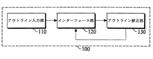
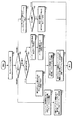
図1は、輪郭分割装置の実施形態を説明するブロック図である。輪郭分割装置100は、CAD診断システムに適用され、CAD診断システムが医療映像から抽出した関心領域(ROI)(例えば、病変領域)をユーザが容易にかつ正確に修正できるようにインターフェースを提示して、診断の正確性を向上させることができる。また、輪郭分割装置100は、CAD診断システム以外の映像処理システムにも適用が可能であり、前記映像処理システムが映像から抽出した関心領域輪郭の正確な分割が可能になるように支援することができる。
FIG. 1 is a block diagram illustrating an embodiment of a contour dividing device. The
図1を参照すれば、輪郭分割装置100は、輪郭入力部110、インターフェース部120、及び輪郭修正部130を含む。
Referring to FIG. 1, the
輪郭入力部110には、映像及びその映像から抽出された関心領域の輪郭の情報が入力される。例えば、輪郭入力部110には、医療映像とCADシステムがその医療映像から抽出した関心領域の情報が入力される。他の実施形態として、輪郭入力部110は、映像を入力され、その映像から関心領域の輪郭を抽出するために、その映像に輪郭分割アルゴリズム、例えば、動的輪郭モデル(Active Contour Model)を適用することができる。
The
インターフェース部120は、ユーザ端末にユーザインタラクティブなインターフェースを提供する。例えば、ユーザ端末は、コンピュータ、ノート型パソコン、スマートフォン、タブレットPC、及び/または当業者に知られた他のハードウェア装置であってよい。インターフェース部120は、ユーザ端末のディスプレイ部(例:モニタ、タッチパネル、及び/または当業者に知られた他のディスプレイ)にインターフェースを出力することができる。ユーザは、提供されるインターフェースを通じて輪郭を修正する各種の動作を容易に行い、輪郭分割装置100は、ユーザが行う各種の動作と一致するユーザ入力を受信し、処理することができる。
The
また、インターフェース部120は、入力されるか、抽出された輪郭に基づいて輪郭を生成し、入力された映像にその生成された輪郭を重畳してインターフェース上に表示することができる。
Further, the
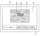
図2は、輪郭分割装置のインターフェース20の実施形態である。図1及び図2を参照して、インターフェース20及びそのインターフェース20を通じる輪郭修正について説明する。
FIG. 2 is an embodiment of the
インターフェース部120によって、ユーザ端末10のディスプレイ部にインターフェース20を出力することができる。インターフェース20は、輪郭25を表示する映像出力領域23とユーザが輪郭モード、すなわち、全体修正モード、部分修正モード、または自由修正モードの選択に使える輪郭修正モード選択領域21とからなる。さらに、ユーザは、入力物体27、例えば、手、指、マウス、スタイラスペン、及び/または当業者に知られた他の入力物体などを用いて映像出力領域23で所定動作を行うことによって、輪郭25を修正することができる。
The
例えば、ユーザは、クリック(click)動作を数回繰り返すか、入力物体27を利用したドラッグ動作、及び/またはタッチパネルから一定方向に移動するパンニング(panning)動作を行うことによって、輪郭25を修正することができる。または、一定時間押す動作を行うことによって、輪郭25を修正することも可能である。このような動作は、1つの実施形態であって、前記図1及び図2の例示に限定されず、その他の既定の多様なジェスチャやマルチタッチを通じて輪郭25を修正することができる。
For example, the user corrects the
輪郭修正部130は、ユーザがインターフェース20上で入力物体27を通じて所定動作を行えば、その動作と一致するユーザの入力を受信し、ユーザが選択したモードとユーザの入力とに基づいて輪郭25を修正する。一実施形態で、輪郭修正部130は、ユーザが輪郭25の内部で所定動作を行えば、例えば、ユーザが最初に動作を行った地点(例:クリック地点、パンニングやドラッグ動作の開始地点など)が輪郭25の内部である場合、輪郭25を内側方向に修正することができる。他の実施形態として、輪郭修正部130は、輪郭25の外部で所定動作を行えば、例えば、ユーザが最初に動作を行った地点(例:クリック地点、パンニングやドラッグ動作の開始地点など)が輪郭の外部である場合、輪郭25を外側方向に修正することができる。さらに他の実施形態として、ユーザがマルチタッチ動作を行う場合、ユーザの2本の指を同時にタッチパネルに接触した状態で互いに遠ざけることによって、輪郭25を外側方向に修正し、互いに近づけることによって、輪郭25を内側方向に修正することができる。
When the user performs a predetermined operation on the
輪郭修正部130は、ユーザが行った動作に対応する入力が輪郭25を内側方向に修正するものであれば、輪郭分割アルゴリズムの閾値(threshold)を元の閾値よりもさらに高く設定して、輪郭輪郭25を減少させることができる。輪郭修正部130は、前記入力が輪郭25を外側方向に修正するものであれば、閾値を元の閾値よりもさらに低く設定して、輪郭を増加させることができる。
If the input corresponding to the action performed by the user is to correct the
輪郭修正部130は、ユーザが行った動作に対応する入力の種類、入力の強度、及び/または入力速度などに基づいて輪郭分割アルゴリズムの閾値を調整することができる。輪郭修正部130は、輪郭25を修正するために調整された閾値を輪郭分割アルゴリズムに適用することができる。
The
例えば、ユーザが行った動作が数回繰り返されたクリック、パンニング、及び/またはドラッグ動作のように不連続的(discrete)な入力を発生させる動作である場合、その閾値の調整幅を相対的に増加させて、輪郭25を再計算することによって、輪郭25が不連続的に変化するように示すことができる。もし、ユーザが行った動作が、所定時間押し続ける動作のような連続的(continuous)な入力を発生させる動作である場合、その閾値の調整幅を相対的に減少させて、輪郭25を再計算することによって、輪郭25が連続して変化するように、ユーザに示すことができる。
For example, when the operation performed by the user is an operation that generates a discrete input such as a click, panning, and / or drag operation that is repeated several times, the threshold adjustment width is relatively set. By increasing and recalculating the
さらに他の例として、閾値の調整幅は、入力の速度に基づいてさらに微細に調整されうる。例えば、ユーザがクリック動作を数回繰り返す時、そのクリック速度を速くすれば、閾値の調整幅を相対的に減少させ、クリック速度を遅くすれば、閾値の調整幅を相対的に増加させて、輪郭25の変化程度を調節することができる。同様に、ユーザが、パンニング動作やドラッグ動作を速くするか、遅くすれば、閾値の調整幅を相対的に増加させるか、減少させて、輪郭の変化程度を調節することができる。
As yet another example, the threshold adjustment range can be finely adjusted based on the input speed. For example, when the user repeats the click operation several times, if the click speed is increased, the threshold adjustment range is relatively decreased, and if the click speed is decreased, the threshold adjustment range is relatively increased, The degree of change of the
また、入力の強度に基づいて閾値の調整幅をさらに微細に調整することによって、輪郭25の変化程度を調節することも可能である。例えば、ユーザが、所定時間押し動作を行う時、その押す圧力または入力強度を増加させれば、閾値の調整幅を相対的に減少させて、さらに連続して変化させうる。さらに他の例として、入力強度を低めれば、閾値の調整幅を相対的に増加させて、相対的に不連続的に変化させうる。
It is also possible to adjust the degree of change of the
また、所定時間ユーザが押す動作を行う場合、あらかじめ時間単位を設定し、その設定された単位の時間が経過する度に閾値の調整幅を調整することによって、閾値を変化させることができる。例えば、3秒単位で押し続ける時間が経過する度に、閾値の調整幅を減らしながら、輪郭25の変化幅を縮めることができる。
Further, when the user performs an operation of pressing for a predetermined time, the threshold value can be changed by setting a time unit in advance and adjusting the adjustment width of the threshold every time the set unit time elapses. For example, each time the time of pressing for 3 seconds elapses, the change width of the
インターフェース部120は、輪郭修正部130によって輪郭25が再計算されれば、該再計算された輪郭25を生成してインターフェース20上に表示することができる。輪郭修正部130によって輪郭25が引き続き修正されれば、インターフェース部120は、修正された輪郭25の変化をインターフェース25に表示することによって、ユーザは、自身が行う動作に基づいて変化する輪郭25を確認することができる。
When the
このような実施形態によれば、インターフェース部120は、ユーザが肉眼で容易に輪郭25の変化を確認できるように、元の輪郭と線の色相、種類、及び/または厚さなどを異ならせてインターフェース20上に表示することができる。例えば、元の輪郭の色相が黒色の実線であれば、修正される輪郭25は、黒色の実線、赤色の実線、及び赤色の点線などの多様な組合わせで表示することができる。
According to such an embodiment, the
一方、ユーザは、輪郭の修正に使われるインターフェース20の輪郭修正モード選択領域21から輪郭修正モードを選択することができる。以下、図3Aないし図5Bを参照して、輪郭修正モードを説明する。
On the other hand, the user can select the contour correction mode from the contour correction
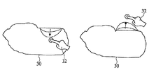
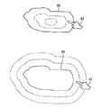
図3Aないし図3Dは、輪郭分割装置100の部分修正モードの実施形態を説明する図面である。図3Aは、部分修正モードで輪郭30を修正する実施形態を説明する図面であって、図3Aに示したように、輪郭30の一部または一定範囲が修正される。図3Aの左側は、ユーザがインターフェースで入力物体32を輪郭30の内部で動作させることによって、内側方向に輪郭30が修正されるものが示されており、図3Aの右側は、ユーザが輪郭30の外部で入力物体32を動作させることによって、輪郭30が外側方向に修正されるものが示されている。
3A to 3D are diagrams illustrating an embodiment of a partial correction mode of the
図1と図3Bとによれば、輪郭修正部130は、ユーザが輪郭修正モードのうちから部分修正モードを選択すれば、輪郭30の一定範囲に対して輪郭分割アルゴリズムを適用して輪郭30を部分的に修正することができる。
According to FIGS. 1 and 3B, the
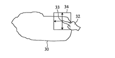
一定範囲は、ユーザが入力物体32を通じて動作を行った最初地点33を中心に既定の範囲34であり得る。もし、既定の範囲34が、輪郭30をいずれも含む程度が大きく設定されている場合には、ユーザが部分修正モードを選択した場合であるとしても、全体修正モードで動作して全体範囲に対する輪郭分割アルゴリズムを適用することができる。
The certain range may be a
また、ユーザは、輪郭分割アルゴリズムが適用された一定範囲を図3C及び図3Dに例示されたように、直接設定することが可能である。図1と図3Cとによれば、インターフェース部120は、ユーザが部分修正モードを選択すれば、基本にあらかじめ指定されているか、ユーザが選択したそれぞれの一定形状(例:円形、楕円形及び多角形、及び/または当業者に知られた他の形状)を含む図形35、36をインターフェース上に出力する。ユーザは、入力物体32を用いてそのそれぞれの図形35、36のサイズを調節することによって、図形35、36に対応するように輪郭30の一定範囲を設定することができる。
Further, the user can directly set a certain range to which the contour division algorithm is applied as illustrated in FIGS. 3C and 3D. According to FIG. 1 and FIG. 3C, the
また、図3Dの上端に示したように、ユーザは、自由領域37に対応する輪郭30の一部を修正するために、入力物体32を通じて輪郭30の一定範囲を自由領域37に対応するように設定することによって、自由領域37を指定することができる。図3Dの下端に示したように、入力物体32を用いて一定範囲を自由曲線38に対応するように設定することによって、輪郭30の一定範囲を自由曲線38形式で選択することができる。
Further, as shown at the upper end of FIG. 3D, the user can make a certain range of the
再び図1と図3C及び図3Dとによれば、インターフェース部120は、ユーザが部分修正モードを選択すれば、輪郭30の修正範囲を設定する方式(例:図形、自由領域、及び自由曲線を通じて)を選択可能なメニュー(例:ポップアップメニューなど)をインターフェースに出力することができる。もし、ユーザが図形を通じる修正範囲設定方式を選択すれば、インターフェース部120は、ユーザが多様な図形のうちの何れか1つの選択に使う追加的なメニューをインターフェース上に出力することができる。
Referring back to FIGS. 1, 3C, and 3D, the
もし、ユーザが、輪郭30の修正に使う一定範囲を全体の輪郭30を含むように設定する場合には、全体修正モードで動作して全体輪郭30範囲に対して輪郭分割アルゴリズムを適用することができる。
If the user sets a fixed range to be used for correcting the
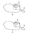
図4は、輪郭分割装置100の全体修正モードの実施形態を説明する図面である。図1と図4とによれば、ユーザがインターフェースの輪郭修正モードのうちから全体修正モードを選択すれば、輪郭修正部130は、ユーザが行う動作に対応する入力に基づいて輪郭40の全体範囲の閾値を調整することによって、全体範囲に輪郭分割アルゴリズムを適用し、再計算することができる。
FIG. 4 is a diagram for explaining an embodiment of the overall correction mode of the
図4の上端に示したように、詳細に説明すれば、ユーザが輪郭40の内部で入力物体42を通じて、例えば、クリック動作などの所定動作を行えば、輪郭修正部130は、閾値を元の閾値よりもさらに高く調整して、輪郭40が内側方向に、すなわち、減少する方向に修正させうる。または、図4の下端に示したように、ユーザが輪郭40の外部で入力物体42を通じて所定動作を行えば、閾値を元の閾値よりも低く調整して、輪郭40が外側方向、すなわち、増加する方向に修正させうる。
As shown in the upper end of FIG. 4, in detail, when the user performs a predetermined operation such as a click operation through the
図5A及び図5Bは、他の輪郭分割装置100の自由修正モードの実施形態を説明する図面である。図1と図5A及び図5Bとを参照すれば、輪郭分割装置100は、ユーザが自在に輪郭を修正できるように自由修正モードを支援することができる。
5A and 5B are diagrams for explaining an embodiment of a free correction mode of another
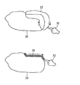
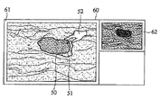
図5Aの上端に示したように、ユーザが、元の輪郭50で修正する部分に対して入力物体52を用いてインターフェースで直接輪郭51を描くことができる。ユーザは、比較的精密に元の輪郭50部分、または全体を修正することができる。輪郭修正部130は、ユーザが輪郭51を直接描く動作に基づいて元の輪郭50を修正することができる。このように、最終的に修正された輪郭53は、図5Bに示したように、インターフェース上に表示される。一方、ユーザは、何回でも自身が希望する輪郭が生成され、表示されるまで輪郭を再び描いて修正することが可能である。
As shown in the upper end of FIG. 5A, the user can directly draw the
図5Bを参照すれば、インターフェース部120は、ユーザがインターフェース60の映像出力領域61に出力された元の輪郭50を修正するために、入力物体52を用いて輪郭51を描けば、インターフェース60の所定領域62にその入力物体52を除き、輪郭51が描かれる部分を表示することができる。これは、ユーザが直接描く輪郭51が、入力物体52によって覆われて、ユーザが見られない場合が発生するので、ユーザに輪郭51が正確に描かれるか否かを確認させるためである。
Referring to FIG. 5B, when the
一定領域62は、ユーザが選択した1つ以上の段階(例:拡大または縮小)で輪郭51が描かれる部分を拡大または縮小するために使う拡大鏡モードを支援し、ユーザは、輪郭51が描かれる部分を段階的に拡大または縮小して正確に描かれているかを容易に確認することができる。
The
図6は、輪郭分割方法の実施形態のフローチャートである。図7は、輪郭分割方法で輪郭修正段階の実施形態の詳細フローチャートである。図6及び図7によって、図1の輪郭分割装置100は、輪郭を分割する方法を行う。
FIG. 6 is a flowchart of an embodiment of the contour dividing method. FIG. 7 is a detailed flowchart of an embodiment of a contour correcting step in the contour dividing method. 6 and 7, the
動作610で、輪郭分割装置100は、1つ以上の輪郭修正モードを支援するインターフェースをユーザ端末に提供することができる。ユーザは、提供されるインターフェースで、例えば、手や指、マウス、スタイラスペン、及び/または当業者に知られた他の入力物体のような多様な入力物体を通じて各種の動作を行うことができる。輪郭分割装置100は、ユーザがインターフェースで行う動作に対応して入力を受信し、処理することができる。
At
輪郭修正モードは、図2に示したように、部分修正モード、全体修正モード、及び/または自由修正モードを含み、ユーザが何れか1つのモードを選択できるように、インターフェースの輪郭修正モード選択領域21にそれぞれのモードを出力することができる。 As shown in FIG. 2, the contour correction mode includes a partial correction mode, a total correction mode, and / or a free correction mode. The contour correction mode selection area of the interface is selected so that the user can select any one mode. 21 can output each mode.
動作620で、輪郭分割装置100は、映像から抽出された関心領域の輪郭をその映像に重畳し、その輪郭を含んだ重畳されたイメージをインターフェース上に表示することができる。輪郭分割装置100は、CAD診断システムや映像処理システムで映像、及び/または輪郭情報を入力されて、その情報に基づいて輪郭を生成し、該生成された輪郭をその入力された映像に重畳して、その重畳された輪郭をインターフェース上に表示することができる。輪郭分割装置100は、映像のみが入力される場合には、その映像で輪郭の情報を抽出することができる。
In
動作630で、輪郭分割装置100は、ユーザが輪郭修正モードのうちの何れかモードを選択し、輪郭を修正する所定動作を行えば、ユーザが選択した輪郭修正モード及びユーザが行った所定動作に対応する入力に基づいて輪郭を修正することができる。
In
図7を参照して、輪郭修正手続きをさらに具体的に説明することができる。図7の動作701で、輪郭分割装置100は、ユーザから選択された輪郭修正モードと所定動作とに対応する入力を受信する。動作702で、輪郭分割装置100は、選択された輪郭修正モードが全体修正モードであるか、部分修正モードであるか、または自由修正であるか否かを判断する。選択された輪郭修正モードが全体修正モードと判断された場合、輪郭分割装置100は、動作703を進行し続ける。選択された輪郭モードが部分修正モードと判断された場合、輪郭分割装置100は、動作705を進行し続ける。選択された修正モードが自由修正モードと判断された場合、輪郭分割装置100は、動作711を進行し続ける。
With reference to FIG. 7, the contour correction procedure can be described more specifically. In
動作703で、輪郭分割装置100は、インターフェースに表示された輪郭の全体範囲に対して輪郭分割装置の閾値、及び/またはパラメータなどを調整する。ユーザが行った動作が行われた地点(例:クリック、パンニング、及びドラッグ動作の開始地点など)を確認して、輪郭の内側方向に修正するか、外側方向に修正するか否かを決定することができる。前述した図4の説明のように、輪郭の内部で動作が行われれば、閾値を元の閾値よりもさらに高く設定して、輪郭を減少させ、輪郭の外部で動作が行われれば、閾値を元の閾値よりもさらに低く設定して、輪郭を増加させうる。
In
また、ユーザが行った動作による入力の種類、強度、及び/または速度などに基づいて閾値の調整幅を互いに異なるように調節することによって、輪郭の変化程度を異ならせうる。前述したように、不連続的な入力であるクリック動作の繰り返し、パンニング、及び/またはドラッグなどの動作が行われれば、閾値の調整幅を増加させて不連続的に輪郭を変化させ、逆に、所定時間押しのように連続的な入力が行われれば、閾値の調整幅を減少させて連続して輪郭を変化させうる。 Further, the degree of change in the contour can be varied by adjusting the threshold adjustment widths to be different from each other based on the type, intensity, and / or speed of the input performed by the user. As described above, if an operation such as repeated click operation, panning, and / or dragging, which is a discontinuous input, is performed, the threshold value is increased and the contour is changed discontinuously. If the continuous input is performed like pressing for a predetermined time, the threshold can be reduced and the contour can be continuously changed.
動作704で、調整された閾値、及び/またはパラメータなどを輪郭分割アルゴリズムに適用して全体の輪郭に対して再計算する。
In
動作705で、輪郭分割装置100は、ユーザが輪郭を修正する一定範囲を設定または修正する要請が入力されたか否かを、例えば、範囲修正要請があったか否かを確認することができる。範囲修正要請が確認された場合、輪郭分割装置100は、動作707を進行するか、それとも動作706を進行し続ける。
In
動作706で、動作を行った最初の地点を中心に一定サイズの範囲で輪郭修正範囲を限定する。
In
動作707で、輪郭分割装置100は、ユーザがインターフェース上で輪郭修正範囲の設定に使える多様なモード(例:範囲設定モードなど)の選択に使えるメニューをインターフェース上に表示または提供することができる。例えば、図3B及び図3Dのように、範囲設定モードは、図形を利用した範囲設定モード、自由領域を利用した範囲設定モード、自由曲線を利用した範囲設定モードなどを含みうる。動作708で、ユーザが選択された範囲設定モードを用いて一定範囲を設定すれば、輪郭分割装置100は、ユーザが直接設定した一定範囲で輪郭の修正範囲を限定する。
In
前述したように、一定サイズの範囲またはユーザによって設定された一定範囲が、インターフェースに表示された輪郭をいずれも含む場合、全体修正モードで動作する。 As described above, when the fixed size range or the fixed range set by the user includes all the contours displayed on the interface, the entire correction mode is operated.
動作709で、限定された一定範囲に対して閾値、及び/またはパラメータなどを調整する。
In
全体修正モードと同様に、限定された一定範囲でユーザが行った動作地点、ユーザが行った動作による入力の種類、強度、及び/または速度に基づいて閾値調整幅を異ならせて調節することによって、輪郭の変化程度を異ならせうる。輪郭分割装置100は、輪郭の限定された一定範囲を再計算するために調整された閾値、及び/またはパラメータなどを輪郭分割アルゴリズムに適用する。動作711で、ユーザが、インターフェースで輪郭を描く動作を行えば、輪郭分割装置100は、その動作に対応する入力に基づいて輪郭を修正し、ユーザによって描かれる輪郭をインターフェース上に表示することができる。
Similar to the overall correction mode, by adjusting the threshold adjustment range differently based on the operation point performed by the user in a limited range, the type, intensity, and / or speed of the input by the operation performed by the user. , The degree of change in contour can be varied. The
動作712で、輪郭分割装置100は、インターフェースの一定領域に入力物体を除き、輪郭が描かれる部分を表示させる拡大要請が入力されたか否かを確認する。動作713で、拡大要請入力が確認されれば、輪郭分割装置100は、動作713を進行し続ける。そうでなければ、輪郭分割方法を終了する。
In
動作713で、その輪郭分割装置100は、その輪郭が描かれる部分をインターフェースの一定領域に拡大して表示する。例えば、ユーザから拡大する情報を入力され、その段階に合わせて拡大して表示することができる。
In
再び図6を参照すれば、動作640で、輪郭分割装置100は、修正された輪郭の変化をインターフェースに表示する。例えば、修正された輪郭の変化をユーザが容易に把握できるように、元の輪郭と修正された輪郭との種類や色相、厚さなどを異ならせて表示することができる。
Referring back to FIG. 6, at
前述したさまざまな装置及び方法は、1つ以上のハードウェア構成要素、1つ以上のソフトウェア構成要素、または1つ以上のハードウェア構成要素と、1つ以上のソフトウェア構成要素との組合わせを使って具現されうる。 The various apparatuses and methods described above use one or more hardware components, one or more software components, or a combination of one or more hardware components and one or more software components. Can be embodied.
ハードウェアの構成要素は、例えば、1つ以上の動作を物理的に行う物理的装置であり得るが、これに限定されるものではない。ハードウェア装置は、マイク、増幅器、低域通過フィルター、高域通過フィルター、帯域通過フィルター、アナログ−デジタルコンバータ、デジタル−アナログコンバータ、及びプロセッシング装置を含む。 A hardware component may be, for example, a physical device that physically performs one or more operations, but is not limited thereto. The hardware device includes a microphone, an amplifier, a low pass filter, a high pass filter, a band pass filter, an analog-to-digital converter, a digital-to-analog converter, and a processing device.
ソフトウェアの構成要素は、例えば、1つ以上の動作を行うソフトウェアや命令語で調節するプロセッシング装置によって実行されるが、それに限定されるものではない。コンピュータ、コントローラ、または他のコントロール装置は、プロセッシング装置がソフトウェアを運用するか、命令語を実行させる。1つのソフトウェア構成要素は、1つのプロセッシング装置で実行され、2つまたはそれ以上のソフトウェア構成要素は、1つのプロセッシング装置で実行され、1つのソフトウェア構成要素は、2つまたはそれ以上のプロセッシング装置で実行され、または、2つまたはそれ以上のソフトウェア構成要素は、2つまたはそれ以上のプロセッシング装置によって実行可能である。 The components of the software are executed by, for example, a software that performs one or more operations or a processing device that is adjusted by an instruction word, but is not limited thereto. A computer, controller, or other control device causes the processing device to operate software or execute instructions. One software component is executed on one processing device, two or more software components are executed on one processing device, and one software component is executed on two or more processing devices. Executed or two or more software components can be executed by two or more processing devices.
プロセッシング装置は、1つ以上の一般−目的または特殊−目的のコンピュータ、例えば、プロセッサ、コントローラ、及び算術論理演算装置、デジタル信号プロセッサ、マイクロコンピュータ、フィールドプログラム可能論理配列、プログラム可能論理演算装置、マイクロプロセッサ、またはソフトウェアを運用するか、命令語を実行する他の装置を使って実行することができる。プロセッシング装置は、運用体制を作動させ、運用体制内で作動する1つ以上のソフトウェアアプリケーションを作動させることができる。プロセッシング装置は、ソフトウェアを運用するか、命令語を実行する場合、データを接近、保存、操作、処理、及び生成することができる。便宜のために、“プロセッシング装置”という用語が、本文で使われるが、当業者は、1つのプロセッシング装置が多様なプロセッシング要素とプロセッシング要素の多様な類型とを含むものと理解できる。例えば、処理装置は、1つ以上の処理器を含むか、1つ以上のプロセッサとコントローラとを含みうる。また、並列プロセッサまたはマルチコアプロセッサのように、他のプロセッシング構成が可能である。 The processing device is one or more general-purpose or special-purpose computers, such as processors, controllers, and arithmetic logic units, digital signal processors, microcomputers, field programmable logic arrays, programmable logic units, micro-computers. It can be implemented using a processor, software, or other device that executes instructions. A processing device can operate an operational regime and can activate one or more software applications that operate within the operational regime. A processing device can access, store, manipulate, process, and generate data when operating software or executing instructions. For convenience, the term “processing device” is used herein, but one skilled in the art will understand that a processing device includes various processing elements and various types of processing elements. For example, the processing device may include one or more processors, or may include one or more processors and a controller. Other processing configurations are possible, such as a parallel processor or a multi-core processor.
動作Aを行うためのソフトウェア構成要素を実行するプロセッシング装置は、ソフトウェアを運用するか、命令語を実行するようにプログラムされたプロセッサを含みうる。また、動作A、動作B、動作Cを行うためのソフトウェア構成要素を実行するプロセッシング装置は、例えば、動作A、B、及びCを行うソフトウェア構成要素を実行するプロセッサ;動作Aを行うソフトウェア構成要素を実行する最初のプロセッサと動作BとCとを行うソフトウェア構成要素を実行する二番目のプロセッサ;動作AとBとを行うソフトウェア構成要素を実行する最初のプロセッサと動作Cを行うソフトウェア構成要素を実行する二番目のプロセッサ;動作Aを行うソフトウェア構成要素を実行する最初のプロセッサ、動作Bを行うソフトウェア構成要素を実行する二番目のプロセッサ、及び動作Cを行うソフトウェア構成要素を実行する三番目のプロセッサ;動作A、B、及びCを行うソフトウェア構成要素を実行する最初のプロセッサと動作A、B、及びCを行うソフトウェア構成要素を実行する二番目のプロセッサ、または1つ以上の動作A、B、及びCをそれぞれ行う1つ以上のプロセッサの他の何れか構成である、多様な構成を含みうる。たとえこのような例が、A、B、Cの3種の動作のみ言及するとしても、行われる動作の数は、3種に限定されず、所望の結果を果たすか、所望の作業を行うための多数の動作があり得る。 A processing device that executes software components for performing operation A may include a processor programmed to operate software or execute an instruction word. In addition, a processing apparatus that executes software components for performing the operations A, B, and C includes, for example, a processor that executes software components that perform the operations A, B, and C; A second processor that executes a software component that performs operations B and C; a first processor that performs a software component that performs operations A and B; and a software component that performs operation C. A second processor that executes; a first processor that executes a software component that performs operation A; a second processor that executes a software component that performs operation B; and a third processor that executes a software component that performs operation C Processor; the software component that performs operations A, B, and C A second processor that executes a software component that performs the operations A, B, and C, or one or more other configurations that each perform one or more operations A, B, and C, respectively. There can be a variety of configurations. Even if such an example mentions only three types of operations A, B, and C, the number of operations to be performed is not limited to three, in order to achieve a desired result or perform a desired operation. There can be many operations.
ソフトウェア構成要素を実行するために、プロセッシング装置を調整するソフトウェアや命令語は、1つ以上の所望の動作を行うために、プロセッシング装置を独立して、または総括的に命令または設定するコンピュータプログラム、コード、命令語、またはその組合わせを含みうる。ソフトウェアまたは命令語は、解釈プログラムを使うプロセッシング装置が行うコンパイラ、及び/または上位レベルコードを生成する機械コードのように、プロセッシング装置が直接に行う機械コードを含みうる。ソフトウェアまたは命令語とデータ、データファイル及びデータ構造と関連した如何なるものも、永久的または一時的に機械、構成要素、物理的、または仮想的装置、コンピュータ記録媒体または装置、命令語やデータを提供することができるか、プロセッシング装置が解釈することができる伝播された信号波動の如何なる形態でも具体化されうる。ソフトウェアまたは命令語とデータ、データファイル及びデータ構造と関連したものは、またネットワークで結合されたコンピュータシステムを通じて分配されることによって、分散された方式で保存されて実行可能である。 Software or instructions that adjust a processing device to execute software components may be a computer program that commands or sets the processing device independently or collectively to perform one or more desired operations; Codes, instruction words, or combinations thereof may be included. The software or instruction word may include machine code directly executed by the processing device, such as a compiler executed by the processing device using the interpreter program, and / or machine code generating high-level code. Anything related to software or instructions and data, data files and data structures may provide permanent or temporary machines, components, physical or virtual devices, computer recording media or devices, instructions or data It can be embodied in any form of propagated signal wave that can be interpreted by the processing device. Software or instructions and associated data, data files and data structures can also be stored and executed in a distributed fashion by being distributed through a networked computer system.
例えば、ソフトウェアまたは命令語、及びデータ、データファイル、及びデータ構造と関連したものは、1つ以上の永久的なコンピュータ可読記録媒体に記録、保存、または固定されうる。永久的なコンピュータ可読記録媒体は、ソフトウェアと命令語及びデータ、データファイル及びデータ構造と関連したものを保存することができる如何なるデータ保存装置もなることができて、それらがコンピュータシステムやプロセッシング装置を通じて判読されうる。永久的なコンピュータ可読記録媒体の例は、読み出し専用メモリ(ROM)、ランダムアクセスメモリ(RAM)、フラッシュメモリ、CD−ROMs、CD−Rs、CD+Rs、CD−RWs、CD+RWs、DVD−ROMs、DVD−Rs、DVD+Rs、DVD−RWs、DVD+RWs、DVD−RAMs、BD−ROMs、BD−Rs、BD−R LTHs、BD−Res、磁気テープ、フロッピー(登録商標)ディスク、光磁気データ保存装置、光データ保存装置、ハードディスク、ソリッドステートディスク、または当業者に知られた永久的なコンピュータ可読記録媒体を含みうる。 For example, software or instructions, and those associated with data, data files, and data structures may be recorded, stored, or fixed in one or more permanent computer readable recording media. Permanent computer readable media can be any data storage device that can store software and instructions and data and related data files, data files, and data structures that can be passed through a computer system or processing device. Can be deciphered. Examples of permanent computer readable recording media are read only memory (ROM), random access memory (RAM), flash memory, CD-ROMs, CD-Rs, CD + Rs, CD-RWs, CD + RWs, DVD-ROMs, DVD- Rs, DVD + Rs, DVD-RWs, DVD + RWs, DVD-RAMs, BD-ROMs, BD-Rs, BD-R LTHs, BD-Res, magnetic tape, floppy (registered trademark) disk, magneto-optical data storage device, optical data storage It may include a device, a hard disk, a solid state disk, or a permanent computer readable recording medium known to those skilled in the art.
本説明と図面とに基づいた実施形態を具現するための機能的なプログラム、コード及びコードセグメントは、本発明が属する技術分野のプログラマーによって容易に構成することができる。ここで説明された端末と装置は、携帯電話、個人デジタル補助器(PDA)、デジタルカメラ、携帯用ゲーム機、MP3プレーヤー、携帯用/個人用マルチプレーヤー、携帯用電子ブック、携帯用ノート型パソコン、グローバルポジショニングシステム、ナビゲーション装置、タブレット、センサー、または固定装置、無線通信、及び/またはネットワーク通信を利用することができるデスクトップPC、高画質テレビ、DVDプレーヤー、ブルーレイプレーヤー、セットトップボックス、ホームオプルライオンス、または当業者に知られた他の装置であり得るが、提示された例に限定されるものではない。 Functional programs, codes, and code segments for implementing the embodiments based on the description and the drawings can be easily configured by a programmer in the technical field to which the present invention belongs. The terminals and devices described here are mobile phones, personal digital assistants (PDAs), digital cameras, portable game consoles, MP3 players, portable / personal multiplayers, portable electronic books, portable notebook computers. , Global positioning system, navigation device, tablet, sensor or fixed device, desktop PC that can use wireless communication and / or network communication, high definition TV, DVD player, Blu-ray player, set top box, home op It can be Lions or other devices known to those skilled in the art, but is not limited to the examples presented.
本発明は、特定の例示を含むが、当業者が、請求範囲及びそれと均等な範囲内でその実施形態の形態と細部事項とを多様に変化させうるということは明白である。前述した実施形態は、発明を限定するための観点ではなく、説明する観点で考慮されなければならない。各実施形態の機能や態様の説明は、他の実施形態の類似した機能または態様に適用することができる。説明された技術が他の順序で行われるか、及び/または記載のシステム、構造、装置、または回路の構成要素が他の方式で結合されるか、及び/または他の構成要素、または、それと均等なものに置き換えられるか、補充される場合にも、適切な結果が得られる。したがって、本発明の範囲は、詳細な説明ではなく、請求項とその均等な範囲とによって決定され、請求項とその均等な範囲とに属するあらゆる変化が、発明の範囲に含まれると解釈されねばならない。 The present invention includes specific examples, but it is obvious that those skilled in the art can make various changes in the form and details of the embodiments within the scope of the claims and the equivalents thereof. The above-described embodiments should be considered from the viewpoint of description, not from the viewpoint of limiting the invention. The description of the functions and aspects of each embodiment can be applied to similar functions or aspects of other embodiments. The described techniques may be performed in other orders, and / or components of the described system, structure, apparatus, or circuit may be combined in other manners, and / or other components, or Appropriate results are also obtained when they are replaced or replenished with equivalents. Therefore, the scope of the present invention should be determined not by the detailed description but by the claims and their equivalents, and all changes belonging to the claims and their equivalents should be construed as being included in the scope of the invention. Don't be.
本発明は、ユーザの相互作用に基づいて映像内の輪郭を分割する装置及び方法関連の技術分野に適用可能である。 The present invention is applicable to a technical field related to an apparatus and method for dividing a contour in an image based on user interaction.
10 ユーザ端末
20、60 インターフェース
23 映像出力領域
25、30、40、50、51、53 輪郭
27、32、42、52 入力物体
33 最初の地点
34 範囲
35、36 図形
37 自由領域
38 自由曲線
61 映像出力領域
62 所定領域
100 輪郭分割装置
110 輪郭入力部
120 インターフェース部
130 輪郭修正部
10
Claims (20)
前記1つ以上のモードからユーザが選択したモード、及び前記ユーザが行った動作に基づいて前記輪郭を修正する輪郭修正部と、
を含む輪郭分割装置。 An interface unit providing an interface supporting one or more modes to the terminal, and displaying an image including a contour of a region of interest on the interface;
A contour correction unit that corrects the contour based on a mode selected by the user from the one or more modes and an operation performed by the user;
Contour dividing apparatus including:
前記増加した調整幅に基づいて前記輪郭が不連続的に変化されるように修正し、
前記動作が前記インターフェース上の所定時間押し続ける動作である場合に、前記閾値の調整幅を減少させ、
前記減少した調整幅に基づいて前記輪郭が連続して変化するように修正する請求項1乃至3のうちのいずれか一項に記載の輪郭分割装置。 The contour correction unit increases an adjustment range of the threshold of the contour when the operation is repeated click, panning, dragging, or a combination thereof on the interface,
Modify the contour to be discontinuously changed based on the increased adjustment width,
When the operation is an operation of pressing and holding on the interface for a predetermined time, the adjustment range of the threshold is decreased,
The contour dividing device according to claim 1, wherein the contour is modified so that the contour continuously changes based on the reduced adjustment width.
関心領域の輪郭を含む映像を前記インターフェース上で表示する段階と、
前記1つ以上のモードからユーザが選択したモードに基づいて前記輪郭を修正する段階と、
を含む輪郭分割方法。 Providing the terminal with an interface that supports one or more modes;
Displaying an image including a contour of a region of interest on the interface;
Modifying the contour based on a mode selected by the user from the one or more modes;
Contour dividing method including:
前記動作を前記輪郭の外部で行う場合に、前記輪郭を外側方向に修正する段階と、
を含む請求項9に記載の輪郭分割方法。 The correcting step includes correcting the contour in an inward direction when the operation is performed inside the contour;
When the operation is performed outside the contour, correcting the contour outwardly;
The contour dividing method according to claim 9, comprising:
前記調整された閾値に基づいて前記輪郭を修正する段階と、
を含む請求項9又は10に記載の輪郭分割方法。 Adjusting the contour threshold based on the motion type, intensity, speed, or combination thereof; and
Modifying the contour based on the adjusted threshold;
The contour dividing method according to claim 9 or 10, comprising:
前記増加した調整幅に基づいて前記輪郭が不連続的に変化されるように修正する段階と、
前記インターフェース上で前記動作が所定時間押し動作である場合に、前記閾値の調整幅を減少させる段階と、
前記減少した調整幅に基づいて前記輪郭が連続して変化されるように修正する段階と、
を含む請求項9乃至11のうちのいずれか一項に記載の輪郭分割方法。 The modifying step includes increasing an adjustment range of the threshold value of the contour when the operation is repeated click, panning, dragging, or a combination thereof on the interface;
Modifying the contour to be discontinuously changed based on the increased adjustment width;
Reducing the threshold adjustment range when the operation is a pressing operation for a predetermined time on the interface;
Modifying the contour to be continuously changed based on the reduced adjustment width;
The contour dividing method according to any one of claims 9 to 11, comprising:
前記1つ以上のモードからユーザが選択したモード、及び前記ユーザが行った動作を前記端末から受信するインターフェース部と、
前記モードと前記動作とに基づいて前記輪郭を修正する輪郭修正部と、
を含む輪郭分割装置。 Transmit the interface containing the video and one or more modes to the terminal,
An interface unit that receives a mode selected by the user from the one or more modes and an operation performed by the user from the terminal;
A contour correcting unit that corrects the contour based on the mode and the operation;
Contour dividing apparatus including:
前記動作の種類、強度、速度、またはその組合わせに基づいて前記輪郭の全体の閾値を調節し、
前記調節された閾値に基づいて前記輪郭の全体を修正する請求項17に記載の輪郭分割装置。 The contour correction unit, when the mode is the overall correction mode,
Adjusting the overall threshold of the contour based on the type of action, intensity, speed, or a combination thereof;
The contour dividing device according to claim 17, wherein the entire contour is corrected based on the adjusted threshold value.
前記動作の種類、強度、速度、またはその組合わせに基づいて前記輪郭の一定範囲の閾値を調節し、
前記調節された閾値に基づいて前記輪郭の前記範囲を修正する請求項17又は18に記載の輪郭分割装置。 When the mode is the partial correction mode, the contour correction unit,
Adjusting a threshold of the range of the contour based on the type, intensity, speed, or combination thereof,
The contour dividing device according to claim 17 or 18, wherein the range of the contour is modified based on the adjusted threshold value.
前記ユーザが前記インターフェース上で前記輪郭を描く前記動作に基づいて前記輪郭を修正し、
修正された前記輪郭を前記インターフェース上でさらに表示する請求項17乃至19のうちのいずれか一項に記載の輪郭分割装置。 When the mode is the free correction mode, the contour correction unit,
Modifying the contour based on the action of the user drawing the contour on the interface;
The contour dividing device according to any one of claims 17 to 19, further displaying the modified contour on the interface.
Applications Claiming Priority (2)
| Application Number | Priority Date | Filing Date | Title |
|---|---|---|---|
| KR1020120135473A KR102123061B1 (en) | 2012-11-27 | 2012-11-27 | Boundary segmentation apparatus and method based on user interaction |
| KR10-2012-0135473 | 2012-11-27 |
Publications (1)
| Publication Number | Publication Date |
|---|---|
| JP2014106980A true JP2014106980A (en) | 2014-06-09 |
Family
ID=49709497
Family Applications (1)
| Application Number | Title | Priority Date | Filing Date |
|---|---|---|---|
| JP2013245211A Pending JP2014106980A (en) | 2012-11-27 | 2013-11-27 | Apparatus and method for segmenting contour in image based on user interaction |
Country Status (5)
| Country | Link |
|---|---|
| US (1) | US10186062B2 (en) |
| EP (1) | EP2736016B1 (en) |
| JP (1) | JP2014106980A (en) |
| KR (1) | KR102123061B1 (en) |
| CN (1) | CN103839254B (en) |
Cited By (4)
| Publication number | Priority date | Publication date | Assignee | Title |
|---|---|---|---|---|
| DE102015111556A1 (en) | 2014-07-31 | 2016-02-04 | Fujifilm Corporation | DEVICE, METHOD AND MEDIUM FOR CORRECTING CURVED LINES |
| JP2016123584A (en) * | 2014-12-26 | 2016-07-11 | 株式会社根本杏林堂 | Medical image display terminal and medical image display program |
| JP2019103818A (en) * | 2014-12-26 | 2019-06-27 | 株式会社根本杏林堂 | Medical image display terminal and medical image display program |
| US11741598B2 (en) | 2019-05-14 | 2023-08-29 | Vuno, Inc. | Method for aiding visualization of lesions in medical imagery and apparatus using the same |
Families Citing this family (15)
| Publication number | Priority date | Publication date | Assignee | Title |
|---|---|---|---|---|
| KR102325345B1 (en) * | 2014-12-15 | 2021-11-11 | 삼성전자주식회사 | Interactive image segmentation apparatus and method |
| EP3109824B1 (en) * | 2015-06-24 | 2019-03-20 | RaySearch Laboratories AB | System and method for handling image data |
| KR20180051288A (en) * | 2016-11-08 | 2018-05-16 | 삼성전자주식회사 | Display apparatus and control method thereof |
| WO2018108933A1 (en) * | 2016-12-13 | 2018-06-21 | Koninklijke Philips N.V. | A method and apparatus for modifying a contour comprising a sequence of points positioned on an image |
| US9939272B1 (en) * | 2017-01-06 | 2018-04-10 | TCL Research America Inc. | Method and system for building personalized knowledge base of semantic image segmentation via a selective random field approach |
| JP6724172B2 (en) * | 2017-01-17 | 2020-07-15 | アルプスアルパイン株式会社 | Coordinate input device |
| EP3503026A1 (en) | 2017-12-20 | 2019-06-26 | Koninklijke Philips N.V. | Device, system and method for interacting with vessel images |
| CN108287895B (en) * | 2018-01-19 | 2020-11-06 | 广东小天才科技有限公司 | Dominant frame adjustment-based question searching method and system and handheld photographing device |
| US20220148323A1 (en) * | 2019-02-28 | 2022-05-12 | Sony Group Corporation | Information processing device, information processing method, and information processing system |
| EP3832597A1 (en) * | 2019-12-06 | 2021-06-09 | Microsoft Technology Licensing, LLC | Refinement of image segmentation |
| KR102298618B1 (en) * | 2020-02-20 | 2021-09-06 | 주식회사 에이모 | Apparatus for creating bounding box and method thereof |
| CN111881370A (en) * | 2020-05-21 | 2020-11-03 | 北京嘀嘀无限科技发展有限公司 | Method and system for describing contour of interest area |
| US11893745B2 (en) * | 2020-12-09 | 2024-02-06 | Raytheon Company | System and method for generating and displaying contours |
| CN114693707B (en) * | 2020-12-31 | 2023-09-26 | 北京小米移动软件有限公司 | Object contour template acquisition method, device, equipment and storage medium |
| KR102348375B1 (en) * | 2021-04-27 | 2022-01-06 | 신용석 | Method, apparatus and coumputer-readable medium for extraction of object in image |
Family Cites Families (20)
| Publication number | Priority date | Publication date | Assignee | Title |
|---|---|---|---|---|
| US6970587B1 (en) | 1997-08-28 | 2005-11-29 | Icad, Inc. | Use of computer-aided detection system outputs in clinical practice |
| US7308126B2 (en) | 1997-08-28 | 2007-12-11 | Icad, Inc. | Use of computer-aided detection system outputs in clinical practice |
| JP4467673B2 (en) | 1999-08-19 | 2010-05-26 | 株式会社東芝 | Ultrasonic diagnostic equipment |
| CA2427590C (en) * | 1999-11-01 | 2008-07-08 | Arthrovision, Inc. | Evaluating disease progression using magnetic resonance imaging |
| US7197181B1 (en) * | 2003-04-09 | 2007-03-27 | Bentley Systems, Inc. | Quick method for color-based selection of objects in a raster image |
| JP4494744B2 (en) | 2003-09-25 | 2010-06-30 | ジーイー・メディカル・システムズ・グローバル・テクノロジー・カンパニー・エルエルシー | Ultrasonic diagnostic equipment |
| JP2008521462A (en) * | 2004-11-27 | 2008-06-26 | ブラッコ イメージング エス.ピー.エー. | 2D / 3D integrated contour editor |
| WO2006126131A1 (en) | 2005-05-25 | 2006-11-30 | Koninklijke Philips Electronics N.V. | Stylus-aided touchscreen control of ultrasound imaging devices |
| AU2006254689B2 (en) | 2005-06-02 | 2012-03-08 | Salient Imaging, Inc. | System and method of computer-aided detection |
| JP2007105352A (en) * | 2005-10-17 | 2007-04-26 | Fujifilm Corp | Difference image display device, difference image display method, and program thereof |
| KR100859434B1 (en) | 2005-11-01 | 2008-09-23 | 주식회사 메디슨 | Image processing system and method for providing contour editing function using multiple sectional plane images |
| EP1952340B1 (en) | 2005-11-21 | 2012-10-24 | Agency for Science, Technology and Research | Superimposing brain atlas images and brain images with delineation of infarct and penumbra for stroke diagnosis |
| US8051386B2 (en) | 2006-12-21 | 2011-11-01 | Sectra Ab | CAD-based navigation of views of medical image data stacks or volumes |
| JP2008252680A (en) * | 2007-03-30 | 2008-10-16 | Omron Corp | Program for portable terminal device, and the portable terminal device |
| US20080281182A1 (en) | 2007-05-07 | 2008-11-13 | General Electric Company | Method and apparatus for improving and/or validating 3D segmentations |
| US8237807B2 (en) * | 2008-07-24 | 2012-08-07 | Apple Inc. | Image capturing device with touch screen for adjusting camera settings |
| US8214756B2 (en) * | 2008-11-25 | 2012-07-03 | Vital Images, Inc. | User interface for iterative image modification |
| US8381125B2 (en) * | 2009-12-16 | 2013-02-19 | Apple Inc. | Device and method for resizing user interface content while maintaining an aspect ratio via snapping a perimeter to a gridline |
| US20110210850A1 (en) * | 2010-02-26 | 2011-09-01 | Phuong K Tran | Touch-screen keyboard with combination keys and directional swipes |
| US8693744B2 (en) * | 2010-05-03 | 2014-04-08 | Mim Software, Inc. | Systems and methods for generating a contour for a medical image |
-
2012
- 2012-11-27 KR KR1020120135473A patent/KR102123061B1/en active IP Right Grant
-
2013
- 2013-10-21 US US14/058,645 patent/US10186062B2/en active Active
- 2013-11-27 JP JP2013245211A patent/JP2014106980A/en active Pending
- 2013-11-27 CN CN201310616460.2A patent/CN103839254B/en active Active
- 2013-11-27 EP EP13194593.3A patent/EP2736016B1/en active Active
Cited By (5)
| Publication number | Priority date | Publication date | Assignee | Title |
|---|---|---|---|---|
| DE102015111556A1 (en) | 2014-07-31 | 2016-02-04 | Fujifilm Corporation | DEVICE, METHOD AND MEDIUM FOR CORRECTING CURVED LINES |
| US10262402B2 (en) | 2014-07-31 | 2019-04-16 | Fujifilm Corporation | Curved line correction apparatus, method, and medium |
| JP2016123584A (en) * | 2014-12-26 | 2016-07-11 | 株式会社根本杏林堂 | Medical image display terminal and medical image display program |
| JP2019103818A (en) * | 2014-12-26 | 2019-06-27 | 株式会社根本杏林堂 | Medical image display terminal and medical image display program |
| US11741598B2 (en) | 2019-05-14 | 2023-08-29 | Vuno, Inc. | Method for aiding visualization of lesions in medical imagery and apparatus using the same |
Also Published As
| Publication number | Publication date |
|---|---|
| KR20140070791A (en) | 2014-06-11 |
| EP2736016A3 (en) | 2017-11-08 |
| US10186062B2 (en) | 2019-01-22 |
| EP2736016A2 (en) | 2014-05-28 |
| EP2736016B1 (en) | 2019-02-06 |
| CN103839254B (en) | 2019-01-25 |
| KR102123061B1 (en) | 2020-06-16 |
| US20140146076A1 (en) | 2014-05-29 |
| CN103839254A (en) | 2014-06-04 |
Similar Documents
| Publication | Publication Date | Title |
|---|---|---|
| JP2014106980A (en) | Apparatus and method for segmenting contour in image based on user interaction | |
| US20170046121A1 (en) | Method and apparatus for providing user interface in an electronic device | |
| KR102137240B1 (en) | Method for adjusting display area and an electronic device thereof | |
| JP2018537755A (en) | Foveal geometry tessellation | |
| US20140098142A1 (en) | System and method for generation and manipulation of a curve in a dynamic graph based on user input | |
| US9489365B2 (en) | User interface for visualizing resizing of table elements | |
| US8771048B2 (en) | Computer-implemented video puzzles | |
| AU2015362286A1 (en) | Method and apparatus for arranging objects according to content of background image | |
| US20140298258A1 (en) | Switch List Interactions | |
| US20110173530A1 (en) | Layout constraint manipulation via user gesture recognition | |
| US9436358B2 (en) | Systems and methods for editing three-dimensional video | |
| US9195364B2 (en) | Method and apparatus for generating dynamic wallpaper | |
| US20140215393A1 (en) | Touch-based multiple selection | |
| US20150113453A1 (en) | Methods and devices for simplified graphical object editing | |
| US8564620B2 (en) | Method for automatically adjusting the rendered fidelity of elements of a composition | |
| WO2019240960A1 (en) | Linked text boxes | |
| EP2911115B1 (en) | Electronic device and method for color extraction | |
| US20200211254A1 (en) | Method and portable electronic device for changing graphics processing resolution according to scenario | |
| JP2014067289A (en) | Information processing apparatus and display control method | |
| KR20160100187A (en) | Apparatus and method for multi-touch input | |
| US9460362B2 (en) | Method and apparatus for identifying a desired object of an image using a suggestive marking | |
| US20200241744A1 (en) | Joystick tool for navigating through productivity documents | |
| KR101644854B1 (en) | Area designating method | |
| KR102347392B1 (en) | Method for providing user interface and electronic device the same | |
| US20160004411A1 (en) | Run-Time Adaptive Non-Uniform Mapping of Gesture User Interface Events |