JP2014074635A - Ultrasonic sensor - Google Patents
Ultrasonic sensor Download PDFInfo
- Publication number
- JP2014074635A JP2014074635A JP2012221901A JP2012221901A JP2014074635A JP 2014074635 A JP2014074635 A JP 2014074635A JP 2012221901 A JP2012221901 A JP 2012221901A JP 2012221901 A JP2012221901 A JP 2012221901A JP 2014074635 A JP2014074635 A JP 2014074635A
- Authority
- JP
- Japan
- Prior art keywords
- ultrasonic sensor
- vibrator
- lower electrode
- protective cover
- piezoelectric element
- Prior art date
- Legal status (The legal status is an assumption and is not a legal conclusion. Google has not performed a legal analysis and makes no representation as to the accuracy of the status listed.)
- Pending
Links
Images


Landscapes
- Investigating Or Analyzing Materials By The Use Of Ultrasonic Waves (AREA)
Abstract
Description
本発明は超音波センサに関し、高温に耐えることができ、且つ、フレキシブルで薄膜状にすることができるように工夫したものである。 The present invention relates to an ultrasonic sensor and is devised so that it can withstand high temperatures and can be made flexible and thin.
各種のプラントでは、多数の配管や容器等が備えられている。このような配管や容器等(以下「配管等」と称する)に、高温(例えば60℃〜600℃)の流体が流通し、または貯留される場合には、経年劣化により、配管等に減肉や亀裂が発生することがある。かかる減肉や亀裂は、内部流体の流れに変化が起こる、湾曲管やエルボ管等の曲面部や、配管等の狭隘部等で発生しやすい。 Various plants are equipped with a large number of pipes and containers. When a high-temperature fluid (for example, 60 ° C. to 600 ° C.) is circulated or stored in such a pipe or container (hereinafter referred to as “pipe or the like”), the pipe is thinned due to aging deterioration. And cracks may occur. Such thinning and cracking are likely to occur in curved portions such as curved tubes and elbow tubes, narrow portions such as pipes, etc. in which the flow of internal fluid changes.
そこで、超音波探傷検査をする超音波センサを用いて、高温状態になる配管等の検査を、プラントの運転期間中に常時監視(モニタリング)しておけば、減肉や亀裂の進展状況を経時的に把握することができ、減肉等の進展予測を精緻に行うことができる。このように、減肉等の進展予測を精緻化することができれば、定期検査時における肉厚測定作業を削減することができると共に、プラントの信頼性が向上し、メンテナンスの合理化を図ることができる。 Therefore, if an ultrasonic sensor that performs ultrasonic flaw detection is used to constantly monitor (monitor) the pipes that are in a high temperature state during the plant operation period, the progress of thinning and cracks over time Can be grasped automatically, and progress prediction such as thinning can be precisely performed. Thus, if the progress prediction such as thinning can be refined, the thickness measurement work at the time of periodic inspection can be reduced, the reliability of the plant can be improved, and the maintenance can be rationalized. .
従来技術に係る高温用の超音波センサとしては、圧電体ニオブ酸リチウム(LiNbO3)の単結晶を用いたものが知られている(例えば特許文献1参照)。 As a high-temperature ultrasonic sensor according to the prior art, one using a single crystal of piezoelectric lithium niobate (LiNbO 3 ) is known (for example, see Patent Document 1).
ところで従来技術に係る高温用の超音波センサでは、金属製の固いケース内に、圧電体ニオブ酸リチウム(LiNbO3)からなる高温用圧電素子や、樹脂製のバッキング材(吸音材)などを納めて構成している。なおバッキング材は、圧電素子の振動をできるだけ早く制動し、振動波数を少なくするために配置される。
このように従来技術に係る高温用の超音波センサは、金属製のケースに高温用圧電素子等を収容した構造であるため、高さが高く嵩が大きいものである。
By the way, in the high-temperature ultrasonic sensor according to the prior art, a high-temperature piezoelectric element made of piezoelectric lithium niobate (LiNbO 3 ), a resin backing material (sound absorbing material), and the like are housed in a hard metal case. Is configured. The backing material is arranged to brake the vibration of the piezoelectric element as soon as possible and reduce the vibration wave number.
As described above, the high-temperature ultrasonic sensor according to the related art has a structure in which a high-temperature piezoelectric element or the like is housed in a metal case, and thus has a high height and a large bulk.
一方、高温の流体を流通等させる配管等は、配管等の外周面を保温材で覆っている。このため、高さが高く嵩が大きい従来技術に係る高温用の超音波センサを常時監視用のセンサとして、配管等の外周面に接触して常設し、更に、超音波センサ及び配管等を保温材で覆うようにすることは、現実的には難しいことであった。
特に狭隘部や曲面部では、センサを取り付けることができる設置スペースが狭いため、従来の超音波センサを取り付けることは困難であった。
なお、検査対象面が曲面である場合には、超音波センサが検査対象面の曲面に倣うことができず、測定結果に誤差が生じる恐れもあった。
On the other hand, piping etc. which distribute | circulate a hot fluid etc. have covered the outer peripheral surfaces, such as piping, with the heat insulating material. For this reason, the ultrasonic sensor for high temperature according to the prior art which is high in height and bulk is always installed as a sensor for continuous monitoring in contact with the outer peripheral surface of the pipe, etc., and the ultrasonic sensor and the pipe are kept warm. It was practically difficult to cover with materials.
In particular, in a narrow part and a curved surface part, it is difficult to attach a conventional ultrasonic sensor because the installation space where the sensor can be attached is small.
When the inspection target surface is a curved surface, the ultrasonic sensor cannot follow the curved surface of the inspection target surface, which may cause an error in the measurement result.
また、高さが高く嵩が大きい従来技術に係る高温用の超音波センサを、配管等の外周面に接触して取り付け、更に、超音波センサ及び配管等を保温材で覆うことができた場合であっても、センサ配置部分が大きく外周側に突出するため、多数の超音波センサを狭隘部等に集中して取り付けようとしても、センサ同士が干渉・衝突してしまい、多数の超音波センサの集中的な取り付けは難しいものであった。 In addition, when the ultrasonic sensor for high temperature according to the related art with high height and bulk is attached in contact with the outer peripheral surface of the pipe etc., and furthermore, the ultrasonic sensor and the pipe etc. can be covered with the heat insulating material However, since the sensor arrangement part is large and protrudes to the outer peripheral side, even if many ultrasonic sensors are concentrated and attached to a narrow part or the like, the sensors interfere with each other and collide with each other. The intensive installation of was difficult.
更に、圧電素子である圧電体ニオブ酸リチウム(LiNbO3)は高温に耐えることはできるが、樹脂製のバッキング材の耐熱特性限界は400℃であるため、超音波センサ全体としての耐熱性も400℃程度に制限されていた。 Furthermore, piezoelectric lithium niobate (LiNbO 3 ), which is a piezoelectric element, can withstand high temperatures, but since the heat resistance limit of the resin backing material is 400 ° C., the heat resistance of the ultrasonic sensor as a whole is also 400. It was limited to about ℃.
本発明は、上記従来技術に鑑み、高温(例えば600℃)に耐えることができ、且つ、フレキシブルで薄膜状の超音波センサを提供することを目的とする。 An object of the present invention is to provide a flexible, thin-film ultrasonic sensor that can withstand high temperatures (for example, 600 ° C.) in view of the above-described prior art.
上記課題を解決する本発明の構成は、
下部電極と、この下部電極の上面の一部に形成した薄膜状の圧電素子と、この圧電素子の上面に形成した薄膜状の上部電極からなる振動子と、
前記振動子を収容する保護カバーと、
前記保護カバーの内面に取り付けられて、前記保護カバーに収容される前記振動子の前記上部電極に接触しつつ、前記振動子を前記上部電極側から前記下部電極側に向かって付勢する導電性の押さえ材と、
前記下部電極の上面に接続されている第1の信号線、及び、前記押さえ材に接続されている第2の信号線とを有することを特徴とする。
この場合、前記下部電極は金属フィルムであり、前記保護カバーは薄板を曲げ加工して形成されていることを特徴とすることもできる。
The configuration of the present invention for solving the above problems is as follows.
A vibrator comprising a lower electrode, a thin film piezoelectric element formed on a part of the upper surface of the lower electrode, and a thin film upper electrode formed on the upper surface of the piezoelectric element;
A protective cover for housing the vibrator;
Conductivity attached to the inner surface of the protective cover and biasing the vibrator from the upper electrode side toward the lower electrode side while contacting the upper electrode of the vibrator housed in the protective cover And the presser
It has the 1st signal line connected to the upper surface of the lower electrode, and the 2nd signal line connected to the pressing material.
In this case, the lower electrode may be a metal film, and the protective cover may be formed by bending a thin plate.
また本発明の構成は、
前記圧電素子は、ニオブ酸リチウムからなり、前記下部電極の上面の一部に、ニオブ酸リチウムを含むセラミック溶液を塗布した後に焼成して形成されていることを特徴とする。
The configuration of the present invention is as follows.
The piezoelectric element is made of lithium niobate, and is formed by applying a ceramic solution containing lithium niobate to a part of the upper surface of the lower electrode, followed by firing.
また本発明の構成は、
前記保護カバーと前記押さえ材との間を絶縁する絶縁部材を備えていることを特徴とする。
The configuration of the present invention is as follows.
An insulating member for insulating between the protective cover and the pressing member is provided.
また本発明の構成は、
前記押さえ材と前記上部電極との間に、導電性と可撓性及び弾性を有する導通緩衝材を配置したことを特徴とする。
The configuration of the present invention is as follows.
A conduction buffer material having conductivity, flexibility, and elasticity is disposed between the pressing material and the upper electrode.
本発明によれば、超音波センサの振動子を、金属フィルムからなる下部電極と、下部電極の上面の一部に形成した薄膜状の圧電素子と、圧電素子の上面に形成した薄膜状の上部電極により構成したため、超音波センサは高温に耐え、しかもフレキシブルなものとなる。
したがって、本発明の超音波センサは、湾曲した検査対象物に容易に取り付けることができると共に、高温の検査対象物のモニタリング検査に使用することができる。
According to the present invention, the ultrasonic sensor vibrator includes a lower electrode made of a metal film, a thin film piezoelectric element formed on a part of the upper surface of the lower electrode, and a thin film upper part formed on the upper surface of the piezoelectric element. Since it is constituted by electrodes, the ultrasonic sensor can withstand high temperatures and be flexible.
Therefore, the ultrasonic sensor of the present invention can be easily attached to a curved inspection object and can be used for monitoring inspection of a high-temperature inspection object.
また信号線を、下部電極のうち圧電素子が形成されていない部分と、押さえ材に接続したため、信号線接続の際に圧電素子を損傷することがなくなり、信頼性の高い超音波センサを実現することができる。 In addition, since the signal line is connected to the portion of the lower electrode where the piezoelectric element is not formed and the pressing member, the piezoelectric element is not damaged when the signal line is connected, and a highly reliable ultrasonic sensor is realized. be able to.
以下、本発明に係る超音波センサを、実施例に基づき詳細に説明する。
なお、各実施例で示す超音波センサは、薄膜状でありその厚さは極めて薄く、例えば0.1mm程度のものであるが、各構成部材を認識できるように、各図では超音波センサの厚さを拡大して示している。
Hereinafter, an ultrasonic sensor according to the present invention will be described in detail based on examples.
The ultrasonic sensor shown in each embodiment is a thin film and has a very thin thickness, for example, about 0.1 mm. However, in order to recognize each component, the ultrasonic sensor is shown in each figure. The thickness is shown enlarged.
〔実施例1〕
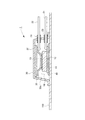
図1は本発明の実施例1に係る高温用の超音波センサ1の構成を示す断面図である。同図に示すように、超音波センサ1の振動子10は、下部電極11と圧電素子12と上部電極13により形成されている。
[Example 1]
FIG. 1 is a cross-sectional view showing a configuration of a high-temperature
下部電極11は厚さが20μm程度の金属フィルムであり、具体的には、SUS(Stainless Steel:ステンレス鋼)薄板、白金薄板、金薄板、またはインコネル薄板などである。
この下部電極11の表面(上面)の一部に、ニオブ酸リチウム(LiNbO3)を含むセラミックス溶液を塗布した後に焼成することにより、キュリー温度が高いニオブ酸リチウム(LiNbO3)からなる薄膜状の圧電素子12が形成される。このため、下部電極11は、上部電極11よりも面積が広くなっている。なお、圧電素子12の厚さは、80μm程度である。
The
A ceramic solution containing lithium niobate (LiNbO 3 ) is applied to a part of the surface (upper surface) of the
上部電極13は厚さが20μm程度の薄膜状の電極であり、金、銀、または白金により形成されている。この上部電極13は、圧電素子12の表面(上面)に、金等の金属ペーストを塗布した後に焼成することにより、または、金等を蒸着することにより、または、金等をめっきすることにより形成されている。あるいは、上部電極13の表面(上面)に、金等の金属ウールを圧着することにより形成されている。
The
下部電極11と圧電素子12と上部電極13により形成されている振動子10は、薄膜状になっているため、振動子10の全体が可撓性及び弾性を有している。
また、振動子10は、高温(例えば600℃)にも耐え得る耐熱性を有している。
Since the
The
一対の信号線21,22のうち信号線21は、下部電極11の表面(上面)のうち圧電素子12が形成されていない部分に、スポット溶接により取り付けられている。これにより、信号線21は振動子10の下部電極11に電気的に接続されている。
なお信号線21,22は後述する保護カバー31を貫通している。保護カバー31の貫通孔には、信号線21,22を通すグロメット23,24が備えられている。グロメット23,24は高温(例えば600℃)にも耐え得る耐熱性を有している。
Of the pair of
The signal lines 21 and 22 pass through a
保護カバー30は、SUS(Stainless Steel:ステンレス鋼)などの金属製の薄板(厚さは例えば0.1mm)を、曲げ加工して形成されており、カバー全体として可撓性及び弾性を有している。この保護カバー30は、その内部空間30a内に振動子10を収容する状態で配置される。
The
保護カバー30の内面(内部空間30a側の面)のうち、振動子10に対向する面(天井面)には、絶縁シート31が取り付けられている。この絶縁シート31は、セラミックシートまたはマイカ箔等により構成されており、可撓性及び弾性を有している。
An insulating
インコネル等の導電材(金属)で形成した押さえ材32は、絶縁シート31に取り付けられている。つまり、押さえ材32は、絶縁シート31により絶縁されて、保護カバー30の内面(天井面)に取り付けられている。
押さえ材32は、導電性を有すると共に、板ばねとしての機能を果たすよう可撓性及び弾性を有している。
A pressing
The pressing
なお、検査対象物である配管等100の表面に配置した振動子10を保護カバー30で覆いつつ、この保護カバー30を配管等100に取り付けたときに、押さえ材32が振動子10の上部電極13に接触しつつ、振動子10を配管等100側に向かって(上部電極13側から下部電極11側に向かって)付勢することができるように、保護カバー30の高さを予め設定している。
Note that when the
保護カバー30、絶縁シート31及び押さえ材32は、全体として可撓性及び弾性を有している。また、保護カバー30、絶縁シート31及び押さえ材32は、高温(例えば600℃)にも耐え得る耐熱性を有している。
The
一対の信号線21,22のうち信号線22は、押さえ材32にスポット溶接されている。このため、配管等100の表面に配置した振動子10を保護カバー30で覆ったときには、信号線22は、押さえ材32を介して、振動子10の上部電極13に電気的に接続される。
Of the pair of
ここで信号線22を、スポット溶接を用いて押さえ材32に接続した理由を説明する。
実施例の超音波センサ1は、300℃以上の高温(例えば600℃)であっても使用できることを目的としているため、かかる高温状態では溶けてしまう「はんだ付け」ではなく、高温に耐え得るスポット溶接を採用した。
また、仮に信号線22を振動子10の上部電極13に直接スポット溶接したとすると、圧電素子12を構成している圧電膜が溶接熱により破損してしまう。
このような事情を考慮して、信号線22を押さえ材32にスポット溶接している。
Here, the reason why the
The
If the
Considering such circumstances, the
なお、前述した信号線21は、下部電極11の表面(上面)のうち圧電素子12が形成されていない部分にスポット溶接されているため、スポット溶接部が高温に耐え得ると共に、スポット溶接の際の熱により圧電素子12が破損してしまうことはない。
The
上記構成となっている超音波センサ1を、検査対象物である配管等100に取り付けて常時監視(モニタリング)する手順を説明する。
A procedure for constantly monitoring (monitoring) the
まず配管等100の表面にカプラント(接触媒質)40を塗布する。カプラント40としては、高温(例えば600℃)に耐え得る、金属ペースト(銀ペーストや金ペースト等)や低融点金属(鉛、スズ、亜鉛等)を用いる。
そして、振動子10の下部電極11の下面を、カプラント40を介して、配管等100の表面に密着する。
First, a coplanar (contact medium) 40 is applied to the surface of the
Then, the lower surface of the
配管等100の表面に密着させた振動子10を、保護カバー30で覆いつつ、この保護カバー30を配管等100にスポット溶接や銀ペースト接着等を用いて取り付ける。そうすると、押さえ材32が、振動子10の上部電極13に接触しつつ、振動子10を配管等100側に向かって(上部電極13側から下部電極11側に向かって)付勢することができる。
The
この状態で、信号線21,22の先端(スポット溶接されている端部とは反対の端部)を、配管等100から離れている検査機器の場所にまで引き出す。
そして、配管等100の外周面と超音波センサ1を、図示しない保温材で覆う。このとき、超音波センサ1は極めて薄いため、保温材で簡単に覆うことができ、また狭い設置スペースであっても取り付けることができる。
かくして、超音波探傷検査をする超音波センサ1を配管等100に常設して、600℃程度の高温環境下でも、常時監視(モニタリング)することができる。
In this state, the leading ends of the
And the outer peripheral surface of piping 100 etc. and the
Thus, the
このとき、超音波センサ1は全体が可撓性及び弾性を有しているため、配管等100の表面が湾曲していても、湾曲した表面に超音波センサ1を押し付けつつ取り付けていくことにより、この湾曲に応じて超音波センサ1全体が湾曲する。
例えば、図2に示すように配管等100の表面が上に凸となる形状になっていても、図3に示すように配管等100の表面が下に凸となる形状になっていても、配管等100の表面形状に応じて超音波センサ1が湾曲して対応することができる。
なお、超音波センサ1が湾曲しても、板ばねとしての機能を持つ押さえ材32が、振動子10の上部金属13の表面を押し付けているので、押さえ材32と上部金属13との電気的接続を確保することができる。
At this time, since the entire
For example, even if the surface of the
Even if the
なお、この超音波センサ1では、保護カバー30により信号線21,22のスポット溶接部等を覆っているため、引張力などの外力が加わっても、溶接部等を保護することができる。
また、押さえ材32は、一つの部材でありながら、板ばねとしての機能と導電体としての機能という2つの機能を併せ持っているため、構成を簡略化でき、超音波センサ1の薄型化や簡易化に寄与している。
In this
Further, since the pressing
なお前述した超音波センサ1では、上部電極13と押さえ材32は、機械的に接合されていないが、上部電極13と押さえ材32を機械的に接合するようにしてもよい。
例えば、圧電素子12の表面(上面)に金等の金属ペーストを塗布したときに、押さえ材32を金属ペーストに接触させ、押さえ材32を金属ペーストに接触させた状態で焼成をすると、焼成により形成された上部電極13と押さえ材32とを機械的に接合することができる。
In the
For example, when a metal paste such as gold is applied to the surface (upper surface) of the
更に、保護カバー30を耐熱性の絶縁材で形成した場合には、絶縁シート31は不要になり、押さえ材32を保護カバー30に直接、取り付けることができる。
Furthermore, when the
〔実施例2〕
次に本発明の実施例2に係る超音波センサ1aを、図4及び図5を参照して説明する。
この超音波センサ1aでは、押さえ材32と上部電極13との間に、導通緩衝材50を配置している。
導通緩衝材50は、金属ペーストを塗布したり、金属箔(軟金属)を介装したり、または金属ウールを介装したりしたものである。導通緩衝材50は、導電性を有することは勿論、可撓性と弾性を有するものである。
[Example 2]
Next, an
In this
The
なお他の部分の構成は、実施例1の超音波センサ1と同様な構成になっている。
In addition, the structure of another part is the structure similar to the
超音波センサ1aでは、押さえ材32と上部電極13との間に導通緩衝材50を配置しているため、押さえ材32と上部電極13との接触状態を改善することができる。具体的には、導通緩衝材50を介しての、押さえ材32と上部電極13との接触面積の増加や、接触抵抗の減少を図ることができる。
また、熱膨張率の差などにより、押さえ材32による振動子10への押さえ力が変動したり減少したりしても、押さえ力の変動等を補完して導通緩衝材50が膨らむことにより、導通緩衝材50を介しての、押さえ材32と上部電極13との接触を確保することができる。
In the
Further, even if the pressing force applied to the
なお上記実施例1,2で示した超音波センサ1,1aは、プラントの運転期間中における高温環境下で常時監視(モニタリング)する際に使用するのみならず、プラントや機器を製造したときに溶接欠陥を常温(60℃以下)で検出する際にも使用することができる。
常温で使用する場合には、押さえ材32をSUS(Stainless Steel:ステンレス鋼)で形成してもよい。
The
When used at room temperature, the pressing
1,1a 超音波センサ
10 振動子
11 下部電極
12 圧電素子
13 上部電極
21,22 信号線
30 保護カバー
30a 内部空間
31 絶縁シート
32 押さえ材
40 カプラント
50 導通緩衝材
100 配管等(検査対象物)
DESCRIPTION OF
Claims (5)
前記振動子を収容する保護カバーと、
前記保護カバーの内面に取り付けられて、前記保護カバーに収容される前記振動子の前記上部電極に接触しつつ、前記振動子を前記上部電極側から前記下部電極側に向かって付勢する導電性の押さえ材と、
前記下部電極の上面に接続されている第1の信号線、及び、前記押さえ材に接続されている第2の信号線と、
を有することを特徴とする超音波センサ。 A vibrator comprising a lower electrode, a thin film piezoelectric element formed on a part of the upper surface of the lower electrode, and a thin film upper electrode formed on the upper surface of the piezoelectric element;
A protective cover for housing the vibrator;
Conductivity attached to the inner surface of the protective cover and biasing the vibrator from the upper electrode side toward the lower electrode side while contacting the upper electrode of the vibrator housed in the protective cover And the presser
A first signal line connected to the upper surface of the lower electrode, and a second signal line connected to the pressing member;
An ultrasonic sensor comprising:
前記下部電極は金属フィルムであり、前記保護カバーは薄板を曲げ加工して形成されていることを特徴とする超音波センサ。 In claim 1,
The ultrasonic sensor according to claim 1, wherein the lower electrode is a metal film, and the protective cover is formed by bending a thin plate.
前記圧電素子は、ニオブ酸リチウムからなり、前記下部電極の上面の一部に、ニオブ酸リチウムを含むセラミック溶液を塗布した後に焼成して形成されていることを特徴とする超音波センサ。 In claim 1 or claim 2,
2. The ultrasonic sensor according to claim 1, wherein the piezoelectric element is made of lithium niobate, and is formed by applying a ceramic solution containing lithium niobate to a part of the upper surface of the lower electrode, followed by firing.
前記保護カバーと前記押さえ材との間を絶縁する絶縁部材を備えていることを特徴とする超音波センサ。 In any one of Claims 1 thru | or 3,
An ultrasonic sensor comprising an insulating member for insulating between the protective cover and the pressing member.
前記押さえ材と前記上部電極との間に、導電性と可撓性及び弾性を有する導通緩衝材を配置したことを特徴とする超音波センサ。 In any one of Claims 1 thru | or 4,
An ultrasonic sensor, wherein a conduction buffer material having conductivity, flexibility and elasticity is disposed between the pressing material and the upper electrode.
Priority Applications (1)
| Application Number | Priority Date | Filing Date | Title |
|---|---|---|---|
| JP2012221901A JP2014074635A (en) | 2012-10-04 | 2012-10-04 | Ultrasonic sensor |
Applications Claiming Priority (1)
| Application Number | Priority Date | Filing Date | Title |
|---|---|---|---|
| JP2012221901A JP2014074635A (en) | 2012-10-04 | 2012-10-04 | Ultrasonic sensor |
Publications (1)
| Publication Number | Publication Date |
|---|---|
| JP2014074635A true JP2014074635A (en) | 2014-04-24 |
Family
ID=50748873
Family Applications (1)
| Application Number | Title | Priority Date | Filing Date |
|---|---|---|---|
| JP2012221901A Pending JP2014074635A (en) | 2012-10-04 | 2012-10-04 | Ultrasonic sensor |
Country Status (1)
| Country | Link |
|---|---|
| JP (1) | JP2014074635A (en) |
Cited By (3)
| Publication number | Priority date | Publication date | Assignee | Title |
|---|---|---|---|---|
| JP2016161537A (en) * | 2015-03-05 | 2016-09-05 | 三菱日立パワーシステムズ株式会社 | Method of installing thin film ultrasonic sensor and ultrasonic flaw detection device |
| JP2017044601A (en) * | 2015-08-27 | 2017-03-02 | 三菱重工業株式会社 | Ultrasonic sensor and method of manufacturing the same |
| CN113654495A (en) * | 2021-08-13 | 2021-11-16 | 北京信泰智合科技发展有限公司 | Ultrasonic sensor for high-temperature pipeline, preparation method and detection system |
Citations (13)
| Publication number | Priority date | Publication date | Assignee | Title |
|---|---|---|---|---|
| JPS4840494A (en) * | 1971-09-14 | 1973-06-14 | ||
| JPH01173694U (en) * | 1988-05-27 | 1989-12-08 | ||
| JPH02293660A (en) * | 1989-05-08 | 1990-12-04 | Toshiba Corp | Ultrasonic transducer and assembly thereof |
| JPH0426365U (en) * | 1990-06-27 | 1992-03-02 | ||
| JPH0536361U (en) * | 1991-10-24 | 1993-05-18 | 三菱重工業株式会社 | Ultrasonic probe for high temperature |
| JPH05227594A (en) * | 1992-02-17 | 1993-09-03 | Olympus Optical Co Ltd | Ultrasonic probe |
| JPH10206399A (en) * | 1997-01-17 | 1998-08-07 | Hitachi Eng & Services Co Ltd | Heat resistant acoustic emission sensor |
| JPH1164663A (en) * | 1997-08-27 | 1999-03-05 | Oki Electric Ind Co Ltd | Production of optical waveguide |
| JPH1168206A (en) * | 1997-08-27 | 1999-03-09 | Oki Electric Ind Co Ltd | Manufacture of waveguide type optical amplification element |
| JP2000287298A (en) * | 1999-03-30 | 2000-10-13 | Toray Techno Kk | Method and element for acoustic emission detection |
| JP2007003443A (en) * | 2005-06-27 | 2007-01-11 | National Institute Of Advanced Industrial & Technology | Abnormal state detection method and sheet-like piezoelectric sensor |
| JP2008175781A (en) * | 2007-01-22 | 2008-07-31 | Saitama Prefecture | Ultrasonic probe for high-temperature application |
| US20120291554A1 (en) * | 2011-05-19 | 2012-11-22 | Hitachi-Ge Nuclear Energy, Ltd. | Heat-Resistant Ultrasonic Sensor and Installation Method Thereof |
-
2012
- 2012-10-04 JP JP2012221901A patent/JP2014074635A/en active Pending
Patent Citations (13)
| Publication number | Priority date | Publication date | Assignee | Title |
|---|---|---|---|---|
| JPS4840494A (en) * | 1971-09-14 | 1973-06-14 | ||
| JPH01173694U (en) * | 1988-05-27 | 1989-12-08 | ||
| JPH02293660A (en) * | 1989-05-08 | 1990-12-04 | Toshiba Corp | Ultrasonic transducer and assembly thereof |
| JPH0426365U (en) * | 1990-06-27 | 1992-03-02 | ||
| JPH0536361U (en) * | 1991-10-24 | 1993-05-18 | 三菱重工業株式会社 | Ultrasonic probe for high temperature |
| JPH05227594A (en) * | 1992-02-17 | 1993-09-03 | Olympus Optical Co Ltd | Ultrasonic probe |
| JPH10206399A (en) * | 1997-01-17 | 1998-08-07 | Hitachi Eng & Services Co Ltd | Heat resistant acoustic emission sensor |
| JPH1164663A (en) * | 1997-08-27 | 1999-03-05 | Oki Electric Ind Co Ltd | Production of optical waveguide |
| JPH1168206A (en) * | 1997-08-27 | 1999-03-09 | Oki Electric Ind Co Ltd | Manufacture of waveguide type optical amplification element |
| JP2000287298A (en) * | 1999-03-30 | 2000-10-13 | Toray Techno Kk | Method and element for acoustic emission detection |
| JP2007003443A (en) * | 2005-06-27 | 2007-01-11 | National Institute Of Advanced Industrial & Technology | Abnormal state detection method and sheet-like piezoelectric sensor |
| JP2008175781A (en) * | 2007-01-22 | 2008-07-31 | Saitama Prefecture | Ultrasonic probe for high-temperature application |
| US20120291554A1 (en) * | 2011-05-19 | 2012-11-22 | Hitachi-Ge Nuclear Energy, Ltd. | Heat-Resistant Ultrasonic Sensor and Installation Method Thereof |
Cited By (3)
| Publication number | Priority date | Publication date | Assignee | Title |
|---|---|---|---|---|
| JP2016161537A (en) * | 2015-03-05 | 2016-09-05 | 三菱日立パワーシステムズ株式会社 | Method of installing thin film ultrasonic sensor and ultrasonic flaw detection device |
| JP2017044601A (en) * | 2015-08-27 | 2017-03-02 | 三菱重工業株式会社 | Ultrasonic sensor and method of manufacturing the same |
| CN113654495A (en) * | 2021-08-13 | 2021-11-16 | 北京信泰智合科技发展有限公司 | Ultrasonic sensor for high-temperature pipeline, preparation method and detection system |
Similar Documents
| Publication | Publication Date | Title |
|---|---|---|
| US10458955B2 (en) | Ultrasonic transducer assembly and system for monitoring structural integrity | |
| JP5406881B2 (en) | Heat-resistant ultrasonic sensor and installation method thereof | |
| JP5576331B2 (en) | Pressure sensor device | |
| JP5880935B2 (en) | Sensor device, sensor module, robot, and manufacturing method of sensor device | |
| JP6256605B2 (en) | Piezoelectric device | |
| US20140331771A1 (en) | Ultrasonic Measurement System | |
| JP2014074635A (en) | Ultrasonic sensor | |
| EP2610016B1 (en) | Device for measuring material thickness | |
| WO2005029912A1 (en) | Ultrasonic vibrator and ultrasonic flowmeter using the same | |
| EP3240641B1 (en) | Flexible ultrasonic transducer and a transducer block | |
| JP2008045989A (en) | Jig for mounting sensor and method for mounting sensor on tubular object | |
| JP5105851B2 (en) | Ultrasonic probe | |
| EP2561342A2 (en) | Ultrasonic transducer with wear plate | |
| JP4244172B2 (en) | Ultrasonic probe for high temperature | |
| JP5838864B2 (en) | Thermocouple mounting method and coated thermocouple | |
| US20240003853A1 (en) | Ultrasound device and method | |
| JPH01145537A (en) | Thermocouple for measuring temperature | |
| JPH10206399A (en) | Heat resistant acoustic emission sensor | |
| JP5734023B2 (en) | Ultrasonic inspection method | |
| JP2003004713A (en) | High temperature sensor | |
| JP2017215278A (en) | Detector of ultrasonic flowmeter | |
| JP2018124081A (en) | Ultrasonic sensor | |
| JPH10153586A (en) | Ultrasonic probe and manufacture thereof | |
| JPWO2004065954A1 (en) | Ultrasonic probe | |
| JP6959082B2 (en) | Temperature measurement probe and battery temperature detector |
Legal Events
| Date | Code | Title | Description |
|---|---|---|---|
| A621 | Written request for application examination |
Free format text: JAPANESE INTERMEDIATE CODE: A621 Effective date: 20150821 |
|
| A131 | Notification of reasons for refusal |
Free format text: JAPANESE INTERMEDIATE CODE: A131 Effective date: 20160426 |
|
| A977 | Report on retrieval |
Free format text: JAPANESE INTERMEDIATE CODE: A971007 Effective date: 20160428 |
|
| A02 | Decision of refusal |
Free format text: JAPANESE INTERMEDIATE CODE: A02 Effective date: 20161108 |