JP2014061057A - Information processor, information processing method, program, and measurement system - Google Patents
Information processor, information processing method, program, and measurement system Download PDFInfo
- Publication number
- JP2014061057A JP2014061057A JP2012206838A JP2012206838A JP2014061057A JP 2014061057 A JP2014061057 A JP 2014061057A JP 2012206838 A JP2012206838 A JP 2012206838A JP 2012206838 A JP2012206838 A JP 2012206838A JP 2014061057 A JP2014061057 A JP 2014061057A
- Authority
- JP
- Japan
- Prior art keywords
- unit
- measurement
- marker
- subject
- information processing
- Prior art date
- Legal status (The legal status is an assumption and is not a legal conclusion. Google has not performed a legal analysis and makes no representation as to the accuracy of the status listed.)
- Pending
Links
Images


Classifications
-
- A—HUMAN NECESSITIES
- A61—MEDICAL OR VETERINARY SCIENCE; HYGIENE
- A61B—DIAGNOSIS; SURGERY; IDENTIFICATION
- A61B5/00—Measuring for diagnostic purposes; Identification of persons
- A61B5/0059—Measuring for diagnostic purposes; Identification of persons using light, e.g. diagnosis by transillumination, diascopy, fluorescence
- A61B5/0077—Devices for viewing the surface of the body, e.g. camera, magnifying lens
-
- A—HUMAN NECESSITIES
- A61—MEDICAL OR VETERINARY SCIENCE; HYGIENE
- A61B—DIAGNOSIS; SURGERY; IDENTIFICATION
- A61B5/00—Measuring for diagnostic purposes; Identification of persons
- A61B5/06—Devices, other than using radiation, for detecting or locating foreign bodies ; determining position of probes within or on the body of the patient
- A61B5/061—Determining position of a probe within the body employing means separate from the probe, e.g. sensing internal probe position employing impedance electrodes on the surface of the body
- A61B5/064—Determining position of a probe within the body employing means separate from the probe, e.g. sensing internal probe position employing impedance electrodes on the surface of the body using markers
-
- A—HUMAN NECESSITIES
- A61—MEDICAL OR VETERINARY SCIENCE; HYGIENE
- A61B—DIAGNOSIS; SURGERY; IDENTIFICATION
- A61B5/00—Measuring for diagnostic purposes; Identification of persons
- A61B5/44—Detecting, measuring or recording for evaluating the integumentary system, e.g. skin, hair or nails
- A61B5/441—Skin evaluation, e.g. for skin disorder diagnosis
-
- G—PHYSICS
- G06—COMPUTING; CALCULATING OR COUNTING
- G06F—ELECTRIC DIGITAL DATA PROCESSING
- G06F18/00—Pattern recognition
- G06F18/20—Analysing
- G06F18/22—Matching criteria, e.g. proximity measures
-
- G—PHYSICS
- G06—COMPUTING; CALCULATING OR COUNTING
- G06T—IMAGE DATA PROCESSING OR GENERATION, IN GENERAL
- G06T1/00—General purpose image data processing
- G06T1/60—Memory management
-
- G—PHYSICS
- G06—COMPUTING; CALCULATING OR COUNTING
- G06T—IMAGE DATA PROCESSING OR GENERATION, IN GENERAL
- G06T7/00—Image analysis
- G06T7/0002—Inspection of images, e.g. flaw detection
- G06T7/0012—Biomedical image inspection
-
- G—PHYSICS
- G06—COMPUTING; CALCULATING OR COUNTING
- G06T—IMAGE DATA PROCESSING OR GENERATION, IN GENERAL
- G06T7/00—Image analysis
- G06T7/50—Depth or shape recovery
- G06T7/55—Depth or shape recovery from multiple images
-
- G—PHYSICS
- G06—COMPUTING; CALCULATING OR COUNTING
- G06T—IMAGE DATA PROCESSING OR GENERATION, IN GENERAL
- G06T7/00—Image analysis
- G06T7/60—Analysis of geometric attributes
-
- G—PHYSICS
- G06—COMPUTING; CALCULATING OR COUNTING
- G06T—IMAGE DATA PROCESSING OR GENERATION, IN GENERAL
- G06T7/00—Image analysis
- G06T7/70—Determining position or orientation of objects or cameras
- G06T7/73—Determining position or orientation of objects or cameras using feature-based methods
-
- A—HUMAN NECESSITIES
- A61—MEDICAL OR VETERINARY SCIENCE; HYGIENE
- A61B—DIAGNOSIS; SURGERY; IDENTIFICATION
- A61B5/00—Measuring for diagnostic purposes; Identification of persons
- A61B5/74—Details of notification to user or communication with user or patient ; user input means
- A61B5/742—Details of notification to user or communication with user or patient ; user input means using visual displays
- A61B5/743—Displaying an image simultaneously with additional graphical information, e.g. symbols, charts, function plots
-
- G—PHYSICS
- G06—COMPUTING; CALCULATING OR COUNTING
- G06T—IMAGE DATA PROCESSING OR GENERATION, IN GENERAL
- G06T2207/00—Indexing scheme for image analysis or image enhancement
- G06T2207/30—Subject of image; Context of image processing
- G06T2207/30004—Biomedical image processing
- G06T2207/30088—Skin; Dermal
-
- G—PHYSICS
- G06—COMPUTING; CALCULATING OR COUNTING
- G06T—IMAGE DATA PROCESSING OR GENERATION, IN GENERAL
- G06T2207/00—Indexing scheme for image analysis or image enhancement
- G06T2207/30—Subject of image; Context of image processing
- G06T2207/30204—Marker
Landscapes
- Engineering & Computer Science (AREA)
- Health & Medical Sciences (AREA)
- Life Sciences & Earth Sciences (AREA)
- Physics & Mathematics (AREA)
- Medical Informatics (AREA)
- General Health & Medical Sciences (AREA)
- Theoretical Computer Science (AREA)
- Surgery (AREA)
- Veterinary Medicine (AREA)
- Molecular Biology (AREA)
- Biophysics (AREA)
- Animal Behavior & Ethology (AREA)
- Biomedical Technology (AREA)
- Public Health (AREA)
- Heart & Thoracic Surgery (AREA)
- Pathology (AREA)
- General Physics & Mathematics (AREA)
- Computer Vision & Pattern Recognition (AREA)
- Human Computer Interaction (AREA)
- Dermatology (AREA)
- Data Mining & Analysis (AREA)
- Radiology & Medical Imaging (AREA)
- Nuclear Medicine, Radiotherapy & Molecular Imaging (AREA)
- Quality & Reliability (AREA)
- Geometry (AREA)
- Artificial Intelligence (AREA)
- Bioinformatics & Cheminformatics (AREA)
- Bioinformatics & Computational Biology (AREA)
- Evolutionary Biology (AREA)
- Evolutionary Computation (AREA)
- General Engineering & Computer Science (AREA)
- Measuring And Recording Apparatus For Diagnosis (AREA)
- Measurement Of The Respiration, Hearing Ability, Form, And Blood Characteristics Of Living Organisms (AREA)
Abstract
Description
本開示は、情報処理装置、情報処理方法、プログラム、及び測定システムに関し、特に、例えば、精度良く定点観測を行えるようにした情報処理装置、情報処理方法、プログラム、及び測定システムに関する。 The present disclosure relates to an information processing device, an information processing method, a program, and a measurement system, and more particularly, to an information processing device, an information processing method, a program, and a measurement system that can perform fixed-point observation with high accuracy.
従来、ユーザの肌の状態を測定する測定器が存在する。この測定器を用いて、ユーザは、例えば肌の同じ箇所を測定することにより、時系列における肌の状態の変化を定点観測することができる。 2. Description of the Related Art Conventionally, there is a measuring instrument that measures a user's skin condition. By using this measuring device, the user can observe a change in the state of the skin in time series at a fixed point, for example, by measuring the same part of the skin.
しかしながら、ユーザは、過去に観測した箇所を、測定時の記憶を頼りに判断して測定を行うため、精度良く同じ箇所を観測できないことがあった。 However, since the user determines a place observed in the past based on the memory at the time of measurement and performs the measurement, the same place may not be observed with high accuracy.
そこで、測定器を使用時のユーザとともに、過去に測定した肌の同じ箇所を示す表示をディスプレイに表示することにより、過去に測定した箇所を、ユーザに認識させるようにした表示認識方法が存在する(例えば、特許文献1参照)。 Therefore, there is a display recognition method that allows the user to recognize a previously measured location by displaying on the display a display showing the same location of the skin measured in the past together with the user when using the measuring instrument. (For example, refer to Patent Document 1).
しかしながら、従来の表示認識方法によれば、ユーザは、過去に測定した箇所を認識できるものの、そのような箇所を測定可能な位置に、測定器を正確に移動させることは難しい。 However, according to the conventional display recognition method, the user can recognize a place measured in the past, but it is difficult to accurately move the measuring instrument to a position where such a place can be measured.
すなわち、ユーザは、測定器を移動させ、測定器が、過去の同じ箇所を測定可能な位置に移動したと判断したところで、測定器に肌の測定を行わせるが、ユーザの判断した位置が、必ずしも、過去の同じ箇所を測定可能な位置であるとは限らない。 In other words, the user moves the measuring device, and when the measuring device determines that the same location in the past has moved to a position where it can be measured, causes the measuring device to measure the skin, but the position determined by the user is It is not always a position where the same place in the past can be measured.
このため、従来の表示認識方法を用いる場合でも、精度良く、肌の同じ箇所を観測できないものとなっていた。 For this reason, even when the conventional display recognition method is used, the same part of the skin cannot be observed with high accuracy.
本開示は、このような状況に鑑みてなされたものであり、精度良く定点観測を行えるようにするものである。 This indication is made in view of such a situation, and makes it possible to perform fixed-point observation with sufficient accuracy.
本開示の第1の側面の情報処理装置は、接近した状態で被写体の一部を測定する測定器に設けられたマーカを、前記被写体とともに撮像する撮像部と、前記撮像部による撮像で得られる撮像画像に基づいて、前記被写体に対する前記マーカの位置を表すマーカ位置を算出する位置算出部と、前記マーカ位置が、前記被写体の一部を測定するときのマーカ位置である測定位置と一致した場合、予め決められた制御処理を行う制御部とを含む情報処理装置である。 The information processing apparatus according to the first aspect of the present disclosure is obtained by imaging a marker provided on a measuring instrument that measures a part of a subject in an approached state together with the subject, and imaging by the imaging unit. A position calculation unit that calculates a marker position that represents the position of the marker with respect to the subject based on a captured image, and the marker position matches a measurement position that is a marker position when measuring a part of the subject An information processing apparatus including a control unit that performs a predetermined control process.
前記マーカは、点灯又は消灯することにより、予め決められた点滅パターンで点滅する発光部であり、前記撮像画像内の前記マーカの点灯又は消灯に基づいて、前記マーカの点滅パターンを検知するパターン検知部をさらに設けることができる。 The marker is a light-emitting unit that blinks in a predetermined blinking pattern by turning on or off, and pattern detection that detects the blinking pattern of the marker based on the turning on or off of the marker in the captured image A part can be further provided.
前記マーカは、前記測定器の状態を表す前記点滅パターンで点滅し、前記パターン検知部の検知結果に基づいて、前記測定器の状態を表示部に表示させる表示制御部をさらに設けることができる。 The marker may further include a display control unit that blinks in the blinking pattern indicating the state of the measuring device and displays the state of the measuring device on a display unit based on a detection result of the pattern detection unit.
前記制御部は、前記マーカ位置が、前記測定器が移動する軌跡上の各測定位置と一致する毎に、予め決められた制御処理を行うことができる。 The control unit can perform a predetermined control process each time the marker position matches each measurement position on the trajectory along which the measuring device moves.
前記制御部は、前記マーカ位置が前記測定位置と一致した場合、その旨をユーザに報知させる第1の前記制御処理、又は前記測定器を制御して、前記測定器に前記被写体の一部を測定させる第2の前記制御処理の少なくとも一方を行うことができる。 When the marker position coincides with the measurement position, the control unit controls the first control process for informing the user of the fact, or the measurement device so that a part of the subject is placed on the measurement device. At least one of the second control processes to be measured can be performed.
前記測定器の傾きを識別する傾き識別部をさらに設けることができる。 An inclination identification unit for identifying the inclination of the measuring device may be further provided.
前記測定器は、前記測定器の動きをセンシングするセンサを有し、前記傾き識別部は、前記センサのセンシング結果に基づいて、前記測定器の傾きを識別することができる。 The measuring device includes a sensor that senses the movement of the measuring device, and the tilt identifying unit can identify the tilt of the measuring device based on a sensing result of the sensor.
前記マーカは、前記測定器の筐体に設けられた図形であり、前記傾き識別部は、前記撮像画像内の前記図形の形状に基づいて、前記測定器の傾きを識別することができる。 The marker is a graphic provided on a housing of the measuring device, and the inclination identifying unit can identify the inclination of the measuring device based on the shape of the graphic in the captured image.
前記測定器は、接近した状態で撮像を行うことにより、前記被写体の肌を測定し、前記測定器の撮像により得られた複数の肌画像に基づいて、前記複数の肌画像をつなぎ合わせた全体肌画像を生成する生成部をさらに設けることができる。 The measuring device measures the skin of the subject by performing imaging in an approached state, and the whole of the plurality of skin images connected based on the plurality of skin images obtained by imaging of the measuring device. A generation unit that generates a skin image can be further provided.
前記測定位置までの距離を測定する距離測定部と、前記測定位置と前記距離に基づいて、前記肌画像の3次元位置を算出する3次元位置算出部とをさらに設け、前記生成部は、複数の前記肌画像の3次元位置にも基づいて、前記被写体の肌を立体的に表示する前記全体肌画像を生成することができる。 A distance measurement unit that measures a distance to the measurement position; and a three-dimensional position calculation unit that calculates a three-dimensional position of the skin image based on the measurement position and the distance; and a plurality of the generation units Based on the three-dimensional position of the skin image, the whole skin image that three-dimensionally displays the skin of the subject can be generated.
前記測定器は、前記被写体の一部に対して、複数の異なる波長の光を照射する照射部と、複数の異なる波長毎に、前記波長の光が照射されているときの肌の撮像を行うことにより、前記被写体の一部を測定するカメラ測定部とを有するようにすることができる。 The measuring device irradiates a part of the subject with an irradiation unit that irradiates light of a plurality of different wavelengths, and performs imaging of the skin when the light of the wavelength is irradiated for each of a plurality of different wavelengths. Thus, a camera measurement unit that measures a part of the subject can be provided.
前記測定器は、前記情報処理装置に着脱自在とすることができる。 The measuring device may be detachable from the information processing apparatus.
前記測定器は、前記情報処理装置に装着された状態で充電可能とすることができる。 The measuring device can be charged while attached to the information processing apparatus.
前記測定器は、前記被写体の一部を接写するカメラ測定部と、前記カメラ測定部を囲む筒状の形状を有し、前記被写体の一部に押し当てられたときにオン状態とされる鏡筒部と、ユーザの回転操作に応じて、前記カメラ測定部の光軸を中心として回転される回転部とを有するようにすることができる。 The measuring device has a camera measurement unit that takes a close-up of a part of the subject, and a cylindrical shape that surrounds the camera measurement unit, and is a mirror that is turned on when pressed against a part of the subject It can have a cylinder part and a rotation part rotated about the optical axis of the camera measurement part according to a user's rotation operation.
前記カメラ測定部は、前記鏡筒部がオン状態とされたときに、前記被写体の一部を接写し、前記回転部は、前記カメラ測定部の動作に関する動作モードを切り替える際に、前記カメラ測定部の光軸を中心として回転されるようにすることができる。 The camera measurement unit takes a close-up image of a part of the subject when the lens barrel unit is turned on, and the rotation unit measures the camera measurement when switching an operation mode related to the operation of the camera measurement unit. It can be rotated about the optical axis of the part.
本開示の第1の側面の情報処理方法は、接近した状態で被写体の一部を測定する測定器に設けられたマーカを、前記被写体とともに撮像する撮像部を有する情報処理装置の情報処理方法であって、前記撮像部による撮像で得られる撮像画像に基づいて、前記被写体に対する前記マーカの位置を表すマーカ位置を算出する位置算出ステップと、前記マーカ位置が、前記被写体の一部を測定するときのマーカ位置である測定位置と一致した場合、予め決められた制御処理を行う制御ステップとを含む情報処理方法である。 An information processing method according to a first aspect of the present disclosure is an information processing method of an information processing apparatus having an imaging unit that images a marker provided on a measuring instrument that measures a part of a subject in an approached state together with the subject. A position calculating step of calculating a marker position representing a position of the marker with respect to the subject based on a captured image obtained by imaging by the imaging unit; and the marker position measures a part of the subject. The information processing method includes a control step of performing a predetermined control process when the measured position is the marker position.
本開示の第1の側面のプログラムは、接近した状態で被写体の一部を測定する測定器に設けられたマーカを、前記被写体とともに撮像する撮像部を有する情報処理装置のコンピュータを、前記撮像部による撮像で得られる撮像画像に基づいて、前記被写体に対する前記マーカの位置を表すマーカ位置を算出する位置算出部と、前記マーカ位置が、前記被写体の一部を測定するときのマーカ位置である測定位置と一致した場合、予め決められた制御処理を行う制御部として機能させるためのプログラムである。 A program according to a first aspect of the present disclosure includes a computer of an information processing apparatus having an imaging unit that images a marker provided in a measuring instrument that measures a part of a subject in an approached state together with the subject. A position calculation unit that calculates a marker position that represents the position of the marker with respect to the subject based on a captured image obtained by imaging, and a measurement in which the marker position is a marker position when measuring a part of the subject A program for causing a control unit to function as a control unit that performs a predetermined control process when the position matches.
本開示の第1の側面によれば、接近した状態で被写体の一部を測定する測定器に設けられたマーカを、前記被写体とともに撮像する撮像部による撮像で得られる撮像画像に基づいて、前記被写体に対する前記マーカの位置を表すマーカ位置が算出され、前記マーカ位置が、前記被写体の一部を測定するときのマーカ位置である測定位置と一致した場合、予め決められた制御処理が行われる。 According to the first aspect of the present disclosure, the marker provided in the measuring device that measures a part of the subject in an approached state is based on a captured image obtained by imaging by the imaging unit that images the subject together with the subject. A marker position that represents the position of the marker with respect to the subject is calculated, and when the marker position matches a measurement position that is a marker position when measuring a part of the subject, a predetermined control process is performed.
本開示の第2の側面の測定システムは、ユーザに接近した状態で測定を行う測定器と、前記ユーザ及び前記測定器を撮像する撮像部を有する情報処理装置から構成される測定システムであって、前記測定器は、接近した状態でユーザの一部を測定する測定部と、前記測定器の筐体に設けられたマーカとを有し、前記情報処理装置は、前記測定器に設けられた前記マーカを、前記ユーザとともに撮像する撮像部と、前記撮像部による撮像で得られる撮像画像に基づいて、前記ユーザに対する前記マーカの位置を表すマーカ位置を算出する位置算出部と、前記マーカ位置が、前記ユーザの一部を測定するときのマーカ位置である測定位置と一致した場合、予め決められた制御処理を行う制御部とを有する測定システムである。 A measurement system according to a second aspect of the present disclosure is a measurement system including a measurement device that performs measurement in a state of approaching a user, and an information processing apparatus that includes an imaging unit that images the user and the measurement device. The measuring device includes a measuring unit that measures a part of the user in an approached state, and a marker provided on a housing of the measuring device, and the information processing device is provided on the measuring device. An imaging unit that images the marker together with the user, a position calculation unit that calculates a marker position representing the position of the marker with respect to the user based on a captured image obtained by imaging by the imaging unit, and the marker position The control system includes a control unit that performs a predetermined control process when it coincides with a measurement position that is a marker position when measuring a part of the user.
本開示の第2の側面によれば、前記測定器により、接近した状態でユーザの一部が測定され、前記情報処理装置により、前記測定器に設けられた前記マーカが、前記ユーザとともに撮像され、その撮像で得られる撮像画像に基づいて、前記ユーザに対する前記マーカの位置を表すマーカ位置が算出され、前記マーカ位置が、前記ユーザの一部を測定するときのマーカ位置である測定位置と一致した場合、予め決められた制御処理が行われる。 According to the second aspect of the present disclosure, a part of a user is measured by the measuring device in an approaching state, and the marker provided on the measuring device is imaged together with the user by the information processing device. Based on the captured image obtained by the imaging, a marker position representing the position of the marker with respect to the user is calculated, and the marker position coincides with a measurement position that is a marker position when measuring a part of the user In such a case, a predetermined control process is performed.
本開示によれば、精度良く定点観測を行うことが可能となる。 According to the present disclosure, it is possible to perform fixed-point observation with high accuracy.
以下、本開示における実施の形態(以下、実施の形態という)について説明する。なお、説明は以下の順序で行う。
1.第1の実施の形態(LED位置が測定位置と一致した場合、その旨を報知するときの一例)
2.第2の実施の形態(LEDの点滅パターンに応じて、測定器の状態を表示するときの一例)
3.第3の実施の形態(LED位置が測定位置と一致した場合、測定を行わせるときの一例)
4.変形例
Hereinafter, embodiments of the present disclosure (hereinafter referred to as embodiments) will be described. The description will be given in the following order.
1. 1st Embodiment (An example when notifying that when LED position corresponds with a measurement position)
2. Second embodiment (an example of displaying the state of a measuring instrument according to the blinking pattern of an LED)
3. Third embodiment (an example in which measurement is performed when the LED position matches the measurement position)
4). Modified example
<1.第1の実施の形態>
[測定システム1の構成例]
図1は、本開示における測定システム1の構成例を示している。
<1. First Embodiment>
[Configuration example of measurement system 1]
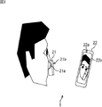
FIG. 1 illustrates a configuration example of a
この測定システム1は、例えば、測定器21及びスマートフォン22から構成され、ユーザの肌に関する肌データを、測定器21で定点観測できるようにするものである。
The
なお、本開示では、測定システム1において、肌データを定点観測するものとして説明するが、定点観測の対象は、肌データに限定されず、頭皮や毛根等に関するデータ、彫刻などの美術品の劣化の度合い(程度)を表すデータ等を対象とすることができる。
In the present disclosure, the
測定器21は、ユーザの肌(例えば、ユーザの顔)に接近した状態で移動され、ユーザの肌に関する肌データを測定する。ここで、接近とは、ユーザの肌までの距離が0であることを表す接触と、ユーザの肌までの距離が近いことを表す近接のいずれも含む概念をいう。
The measuring
また、肌データとしては、ユーザの肌の状態を表すデータ(例えば、肌の弾力性やたるみ等を示す数値データ)や、ユーザの肌の状態を判別するためのデータ(例えば、肌を撮像して得られた肌画像)等を採用することができる。 Skin data includes data representing the user's skin condition (for example, numerical data indicating the elasticity and sagging of the skin) and data for determining the user's skin condition (for example, imaging the skin). The skin image obtained in this way can be used.
なお、第1の実施の形態において、測定器21は、ユーザの肌を接写するカメラ21aを内蔵し、内蔵するカメラ21aを用いて、肌データとしての肌画像を測定するものとして説明する。しかし、測定器21による肌データの測定方法は、カメラ21aを用いる測定方法に限定されず、肌データを測定できればどのような測定方法であってもよい。
In the first embodiment, the measuring
また、測定器21において、測定器21の背面(ユーザの肌と接近する面とは反対側の面)には、LED(Light Emitting Diode)21bが設けられている。このLED21bは、測定器21の位置をスマートフォン22に識別させるために点灯する。
Further, in the measuring
なお、測定器21には、LED21bが設けられるものとしたが、測定器21の位置をスマートフォン22に識別させるためのマーカであれば、LED21bに限定されず、どのようなマーカを設けるようにしてもよく、例えば、2次元バーコード等の図面を採用することができる。
The measuring
スマートフォン22は、被写体としてのユーザとともにLED21bの撮像を行う撮像部22a、及び撮像部22aの撮像により得られる撮像画像等を表示するLCD(Liquid Crystal Display)22bを有する。
The
なお、LED21bは、撮像部22aで受光(認識)可能な波長の光で発光することにより点灯する。LED21bは、可視光の他、LED21bによる眩しさを避けるために、紫外や赤外等の不可視光で点灯するようにしてもよい。このことは、図4及び図5で後述する、LED21bが点滅する場合についても同様である。
The
ユーザは、図1に示されるように、測定器21を顔に接近させた状態で、スマートフォン22のLCD22bに表示される撮像画像を参照しながら、測定器21を移動させる。
As shown in FIG. 1, the user moves the measuring
スマートフォン22は、撮像部22aから得られる撮像画像に基づいて、ユーザに対するLED21bの位置(LED位置)が、測定器21による測定が行われるときのLED位置を表す測定位置であるか否かを判定する。
The
そして、例えば、スマートフォン22は、LED位置が測定位置であると判定した場合、その旨を報知する報知処理を行う。このとき、ユーザは、測定器21を操作して、測定器21に測定を行わせることにより、顔における同一の箇所を定点観測することができる。
For example, when the
つまり、測定器21は、常に、ユーザの顔における同一の箇所の肌画像を測定することができる。
That is, the measuring
なお、スマートフォン22が行う報知処理については、図2及び図3を参照して詳述する。また、スマートフォン22は、報知処理とは異なる処理も行うが、その処理については、図4以降で説明する。
The notification process performed by the
次に、図2は、図1のスマートフォン22における第1の構成例を示している。
Next, FIG. 2 has shown the 1st structural example in the
図2のスマートフォン22は、撮像部22a及びLCD22bの他、ユーザ識別部61、位置算出部62、判定部63、出力制御部64、スピーカ65、表示制御部66、主制御部67、及び操作部68から構成される。
The
なお、撮像部22aは、ユーザ及び測定器21のLED21bを撮像し、その撮像により得られる撮像画像を、ユーザ識別部61、位置算出部62、及び表示制御部66に供給する。
The
撮像部22aは、光学系41、撮像素子42、及び信号処理IC(Integrated Circuit)43から構成されている。
The
光学系41は、入射される光(例えば、ユーザからの反射光など)を集光するレンズや、入射される光の光量を調整する図示せぬ絞り等から構成される。光学系41は、入射される光を、撮像素子42の受光面に結像させる。
The
撮像素子42は、光学系41により結像された光を光電変換し、その結果得られる画像信号を、信号処理IC43に出力する。なお、撮像素子42としては、例えば、CCD(Charge Coupled Device)やCMOS(Complementary Metal Oxide Semiconductor)等の撮像素子を採用することができる。
The
信号処理IC43は、撮像素子42からの画像信号に所定の画像処理を施し、画像処理後の画像信号を表す撮像画像を、ユーザ識別部61、位置算出部62、及び表示制御部66に供給する。
The
ユーザ識別部61は、撮像部22aからの撮像画像に基づいて、被写体としてのユーザを識別する。
The
すなわち、例えば、ユーザ識別部61は、撮像部22aからの撮像画像から、ユーザの顔等を検出し、その検出結果に基づいて、ユーザを識別する。そして、ユーザ識別部61は、その識別結果を、判定部63に供給する。
That is, for example, the
なお、ユーザの顔等の検出方法としては、例えば、撮像画像の全領域のうち、肌色の部分を、ユーザの顔として検出する方法を採用することができる。 In addition, as a detection method of a user's face etc., the method of detecting the skin color part as a user's face among all the areas | regions of a captured image, for example can be employ | adopted.
位置算出部62は、撮像部22aからの撮像画像に基づいて、ユーザに対するLED21bの位置(LED位置)を算出し、判定部63に供給する。
The
すなわち、例えば、位置算出部62は、撮像部22aからの撮像画像から、肌色の領域を、ユーザの顔として検出するとともに、予め決められた閾値以上の輝度の領域を、点灯中のLED21bとして検出する。なお、LED21bは、LED位置の算出のために、測定器21により点灯される。
That is, for example, the
そして、位置算出部62は、ユーザの顔及びLED21bの検出結果に基づいて、LED位置を算出し、判定部63に供給する。
Then, the
判定部63は、メモリ63aを内蔵している。メモリ63aには、複数の異なるユーザ毎に、測定位置が対応付けて記憶されている。ここで、測定位置とは、定点観測のために、測定器21により、同じ箇所を測定するときのLED位置を表す。測定位置としては、例えば、測定器21が過去に測定したときのLED位置を採用することができる。
The
なお、メモリ63aには、測定位置として、1の位置の他、複数の位置を記憶させるようにすることができる。
The
すなわち、測定器21により測定される箇所を表す測定領域が、1回の測定により測定できる程に小さな領域である場合、その領域を測定する1の測定位置が保持される。
That is, when the measurement region representing the location measured by the measuring
また、測定領域が、後述する図8に示す測定領域121のように、複数回の測定を必要とする大きな領域である場合、その領域を測定する複数の測定位置が保持される。
In addition, when the measurement area is a large area that requires a plurality of measurements, such as a
なお、測定器21は、1のユーザのみに使用される場合、メモリ63aには、そのユーザの測定位置のみが記憶されていることとなる。この場合、図2のスマートフォン22において、ユーザ識別部61を省略することができる。
When the measuring
また、判定部63は、ユーザ識別部61からの識別結果に基づいて、内蔵するメモリ63aから、ユーザ識別部61で識別されたユーザに対応付けられた測定位置を読み出す。
Further, the
そして、判定部63は、位置算出部62からのLED位置が、メモリ63aから読み出した測定位置と一致するか否かを判定し、一致すると判定した場合、その旨を、出力制御部64に通知する。
Then, the
出力制御部64は、判定部63からの通知が行われたことに対応して、スピーカ65を制御し、LED位置が測定位置と一致したことを表す電子音を、スピーカ65から出力させる。
The
なお、第1の実施の形態において、図2のスマートフォン22は、LED位置が測定位置と一致した場合、スピーカ65から電子音を出力することにより、その旨を、ユーザに報知するが、報知方法は、これに限定されない。
In the first embodiment, when the LED position matches the measurement position, the
すなわち、例えば、図2のスマートフォン22は、スピーカ65又はLCD22bの少なくとも一方を用いて、LED位置が測定位置と一致した旨を、ユーザに報知することができる。
That is, for example, the
LCD22bに、LED位置が測定位置と一致した旨を表示する場合には、表示制御部66は、判定部63からの通知が行われたことに対応して、LCD22bを制御し、LED位置が測定位置と一致したことを表す表示を、LCD22bに表示させる。
When displaying that the LED position matches the measurement position on the
この場合、判定部63は、LED位置が測定位置と一致したと判定した場合、その旨を表示制御部66に通知するものとする。
In this case, when it is determined that the LED position matches the measurement position, the
スピーカ65は、例えば、出力制御部64からの制御に従って、電子音を出力する。なお、第1の実施の形態では、スマートフォン22を例にして説明しているため、スピーカ65は、スマートフォン22の一部として構成されるようにしたが、外部に設けられているようにしてもよい。このことは、LCD22bについても同様のことが言える。
For example, the
表示制御部66は、撮像部22aからの撮像画像を、LCD22bに供給して表示させる。これにより、LCD22bには、図1に示したように、被写体としてのユーザとともに、測定器21が、撮像画像として表示される。
The
また、例えば、表示制御部66は、撮像部22aからの撮像画像に、測定位置を表す位置表示を重畳し、重畳後の撮像画像をLCD22bに表示させるようにしてもよい。
Further, for example, the
この場合、LCD22bには、測定器21のLED21bと位置表示が表示される。そして、ユーザは、LCD22bの表示画面を参照しながら、測定器21のLED21bと位置表示が一致するように、測定器21を移動させる。
In this case, the
このため、ユーザは、LCD22bに位置表示が表示されない場合と比較して、より迅速に、測定器21による定点観測を行うことが可能となる。
For this reason, the user can perform fixed-point observation by the measuring
また、例えば、測定器21の測定対象が、後述する図8に示す測定領域121のように、複数回の測定を必要とする大きな領域である場合、表示制御部66は、測定領域121において、測定済みの箇所と、未測定の箇所を区別して表示させるようにしてもよい。
Further, for example, when the measurement target of the measuring
この場合、ユーザは、LCD22bを参照することにより、測定済みの箇所と、未測定の箇所を容易に把握できるので、測定器21による測定漏れを防止することができる。
In this case, the user can easily grasp the measured part and the unmeasured part by referring to the
その他、例えば、表示制御部66は、撮像部22aからの撮像画像を無視(破棄)して、LCD22bには撮像画像を表示させないようにしてもよい。
In addition, for example, the
主制御部67は、例えば、操作部68からの操作信号に基づいて、撮像部22a、ユーザ識別部61、位置算出部62、判定部63、出力制御部64、及び表示制御部66を制御する。
The main control unit 67 controls, for example, the
操作部68は、ユーザに操作される操作ボタン等であり、ユーザに操作されたことに対応して、ユーザの操作に対応する操作信号を、主制御部67に供給する。なお、操作部68は、ユーザからの接触操作を検知するタッチパネルとして、LCD22bに設けられるようにしてもよい。
The
[図2のスマートフォン22の動作説明]
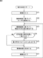
次に、図3のフローチャートを参照して、図2のスマートフォン22が行う報知処理について説明する。
[Description of operation of the
Next, the notification process performed by the
この報知処理は、例えば、ユーザが、操作部68を用いて、報知処理を実行するアプリケーションを起動させるための起動操作を行ったときに開始される。
This notification process is started, for example, when the user uses the
このとき、操作部68は、ユーザの起動操作に対応する操作信号を、主制御部67に供給する。主制御部67は、操作部68からの操作信号に基づいて、撮像部22a、ユーザ識別部61、位置算出部62、判定部63、出力制御部64、及び表示制御部66を制御する。
At this time, the
なお、検知処理の実行時には、LED21bは点灯中であるものとする。
It is assumed that the
ステップS21では、撮像部22aは、主制御部67からの制御に従って、ユーザ及びLED21bを撮像し、その撮像により得られる撮像画像を、ユーザ識別部61、位置算出部62、及び表示制御部66に供給する。
In step S <b> 21, the
ステップS22では、ユーザ識別部61は、撮像部22aからの撮像画像に基づいて、被写体としてのユーザを識別し、その識別結果を判定部63に供給する。
In step S <b> 22, the
ステップS23では、位置算出部62は、撮像部22aからの撮像画像に基づいて、ユーザに対するLED21bの位置を、LED位置として算出し、判定部63に供給する。
In step S23, the
ステップS24では、判定部63は、ユーザ識別部61からの識別結果に基づいて、内蔵するメモリ63aから、ステップS22の処理で識別されたユーザに対応付けられた測定位置を読み出す。
In step S24, the
そして、判定部63は、位置算出部62からのLED位置が、メモリ63aから読み出した測定位置と一致するか否かを判定し、一致すると判定した場合、その旨を、出力制御部64に通知して、処理をステップS25に進める。
Then, the
ステップS25では、出力制御部64は、判定部63からの通知が行われたことに対応して、スピーカ65を制御し、LED位置が測定位置と一致したことを表す電子音を、スピーカ65から出力させる。
In step S <b> 25, the
なお、ステップS24において、判定部63は、位置算出部62からのLED位置が、メモリ63aから読み出した測定位置と一致しないと判定した場合、ステップS25をスキップして処理をステップS26に進める。
In step S24, when the
ステップS26では、表示制御部66は、撮像部22aからの撮像画像を、LCD22bに供給して表示させる。これにより、LCD22bには、図1に示したように、被写体としてのユーザとともに、測定器21が、撮像画像として表示される。
In step S26, the
ステップS27では、撮像部22aは、ステップS21の場合と同様にして、ユーザ、及び測定器21のLED21bを撮像し、その撮像により得られる撮像画像を、ユーザ識別部61、位置算出部62、及び表示制御部66に供給する。その後、処理は、ステップS23に戻り、それ以降、同様の処理が行われる。
In step S27, the
なお、この報知処理は、例えば、ユーザが、操作部68を用いて、報知処理を実行するアプリケーションを中止する操作を行ったときに終了される。
Note that this notification process is terminated when, for example, the user performs an operation of canceling the application that executes the notification process using the
以上説明したように、報知処理によれば、例えば、LED位置が測定位置と一致した場合、出力制御部64は、スピーカ65を制御して、その旨を表す電子音を出力させるようにした。
As described above, according to the notification process, for example, when the LED position coincides with the measurement position, the
このため、ユーザは、スピーカ65からの電子音により、LED位置が測定位置と一致したことを容易に認識することができる。
For this reason, the user can easily recognize that the LED position matches the measurement position by the electronic sound from the
したがって、ユーザは、スピーカ65から電子音が出力されたときに、測定器21に測定を行わせるための測定ボタン(図示せず)を押下することにより、測定器21に、ユーザの顔の同じ箇所から、肌データを繰り返し測定させることができる。
Therefore, when an electronic sound is output from the
よって、ユーザは、測定器21を用いて、ユーザの顔の同じ箇所を、定点観測することが可能となる。
Therefore, the user can use the measuring
また、ユーザは、スピーカ65から電子音が出力されたときのみ、測定器21に肌の測定を行わせればよいので、測定器21に常に肌の測定を行わせる場合と比較して、消費電力を抑制することができる。
Further, since the user only needs to cause the measuring
ところで、第1の実施の形態において、報知処理の実行時には、LED21bを常に点灯させておくようにしたが、例えば、測定器21は、肌データの測定を開始するとき等には、その旨を表す点滅パターンで、LED21bを点滅させるように構成することができる。
By the way, in the first embodiment, the
この場合、スマートフォン22は、撮像部22aから得られる撮像画像内のLED21bの点灯又は消灯に基づいて、LED21bの点滅パターンを検知し、検知した点滅パターンが表す測定器21の状態を、LCD22bに表示する状態表示処理を行う。この状態表示処理は、第2の実施の形態として、図4及び図5を参照して詳述する。
In this case, the
ここで、測定器21の状態としては、例えば、測定の進捗状態や、測定器21が内蔵するカメラ21aの撮像状態等を採用することができる。
Here, as the state of the measuring
なお、測定の進捗状態としては、例えば、測定を開始しようとしていることを示す状態、肌データを測定中であることを示す状態、測定を終了しようとしていることを示す状態等が考えられる。 As the measurement progress state, for example, a state indicating that the measurement is about to be started, a state indicating that the skin data is being measured, a state indicating that the measurement is about to be ended, and the like are conceivable.
また、カメラ21aの撮像状態としては、例えば、カメラ21aが複数の動作モードで動作する場合、肌に可視光を照射した状態で撮像を行う動作モードであることを表す状態や、赤外線を照射した状態で撮像を行う動作モードであることを表す状態等が考えられる。
Moreover, as an imaging state of the
<2.第2の実施の形態>
[スマートフォン22の構成例]
次に、図4は、状態表示が重畳された撮像画像を表示できるようにしたスマートフォン22の構成例を示している。
<2. Second Embodiment>
[Configuration example of smartphone 22]
Next, FIG. 4 shows a configuration example of the
なお、図4のスマートフォン22において、図2の場合と同様に構成される部分については同一の符号を付すようにしているので、それらの説明は、以下、適宜省略する。
In addition, in the
すなわち、図4のスマートフォン22では、図2の表示制御部66に代えて、パターン検知部81、状態識別部82、及び表示制御部83が設けられている他は、図2の場合と同様に構成される。
That is, the
パターン検知部81には、撮像部22aから撮像画像が供給される。パターン検知部81は、撮像画像22aから供給される撮像画像に基づいて、LED21bの点灯又は消灯の一方を検知する。
A captured image is supplied to the
すなわち、例えば、パターン検知部81は、撮像画像22aからの撮像画像の各輝度のうち、予め決められた閾値以上の輝度が存在する場合、LED21bの点灯を検知し、閾値以上の輝度が存在しない場合、LED21bの消灯を検知する。
That is, for example, the
そして、パターン検知部81は、撮像部22aから供給される各撮像画像により得られた複数の検知結果を、LED21bの点滅パターンとして、撮像画像とともに、状態識別部82に供給する。
And the
状態識別部82は、パターン検知部81からの点滅パターンに基づいて、測定器21の状態を識別し、その識別結果を、パターン検知部81からの撮像画像とともに、表示制御部83に供給する。
The
すなわち、例えば、状態識別部82は、パターン検知部81からの点滅パターンが、測定器21の状態を表す状態パターンと一致するか否かを判定する。
That is, for example, the
そして、状態識別部82は、点滅パターンが状態パターンと一致しないと判定した場合、パターン検知部81からの撮像画像のみを、表示制御部83に供給する。
When the
また、状態識別部82は、点滅パターンが状態パターンと一致すると判定した場合、その状態パターンが表す状態を、測定器21の状態として識別し、その識別結果を、パターン検知部81からの撮像画像とともに、表示制御部83に供給する。
When the
なお、状態識別部82は、図示せぬ内蔵のメモリに、複数の異なる状態パターンを予め保持しているものとする。
Note that the
表示制御部83は、図2の表示制御部66と同様に、状態識別部82からの撮像画像を、LCD22bに供給して表示させる。
The
また、表示制御部83は、状態識別部82から、測定器21の状態を表す識別結果が供給された場合、その識別結果に基づいて、状態識別部82からの撮像画像に、測定器21の状態を表す状態表示を重畳する。
In addition, when an identification result representing the state of the measuring
そして、表示制御部83は、状態表示を重畳後の撮像画像を、LCD22bに供給して表示させる。
Then, the
[図4のスマートフォン22の動作説明]
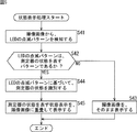
次に、図5のフローチャートを参照して、図4のスマートフォン22が行う状態表示処理について説明する。
[Description of operation of the
Next, a state display process performed by the
なお、図4のスマートフォン22では、図3のステップS26の処理に代えて、状態表示処理を行う以外は、図2のスマートフォン22が行う報知処理と同様の処理を行う。このため、図5のフローチャートでは、状態表示処理のみを説明することとする。
Note that the
ステップS41では、パターン検知部81は、撮像画像22aから供給される撮像画像に基づいて、LED21bの点灯又は消灯の一方を検知する。
In step S41, the
すなわち、例えば、パターン検知部81は、撮像画像22aからの撮像画像の各輝度のうち、予め決められた閾値以上の輝度が存在する場合、LED21bの点灯を検知し、閾値以上の輝度が存在しない場合、LED21bの消灯を検知する。
That is, for example, the
そして、パターン検知部81は、撮像部22aから供給される各撮像画像により得られた複数の検知結果を、LED21bの点滅パターンとして、撮像画像とともに、状態識別部82に供給する。
And the
ステップS42では、状態識別部82は、パターン検知部81からの点滅パターンが、測定器21の状態を表す状態パターンと一致するか否かを判定する。
In step S <b> 42, the
そして、状態識別部82は、点滅パターンが状態パターンと一致しないと判定した場合、パターン検知部81からの撮像画像のみを、表示制御部83に供給して、処理をステップS43に進める。
If the
ステップS43では、表示制御部83は、状態識別部82からの撮像画像を、LCD22bに供給してそのまま表示させ、状態表示処理は終了する。
In step S43, the
また、ステップS42において、状態識別部82は、点滅パターンが状態パターンと一致すると判定した場合、処理をステップS44に進め、その状態パターンが表す状態を、測定器21の状態として識別する。
In step S42, when the
そして、状態識別部82は、その識別結果を、パターン検知部81からの撮像画像とともに、表示制御部83に供給して、処理をステップS45に進める。
And the
ステップS45では、表示制御部83は、状態識別部82からの、測定器21の状態を表す識別結果に基づいて、同じく状態識別部82からの撮像画像に、測定器21の状態を表す状態表示を重畳する。
In step S <b> 45, the
そして、表示制御部83は、状態表示を重畳後の撮像画像を、LCD22bに供給して表示させ、状態表示処理は終了する。
Then, the
以上説明したように、状態表示処理によれば、表示制御部83は、測定器21のLED21bの点滅パターンに基づいて、測定器21の状態を、LCD22bに表示させるようにした。
As described above, according to the state display process, the
このため、ユーザは、図4のスマートフォン22のLCD22bを参照することにより、測定器21の状態(例えば、測定器21が測定中である状態など)を容易に把握することが可能となる。
For this reason, the user can easily grasp the state of the measuring instrument 21 (for example, the state in which the measuring
なお、スマートフォン22は、LED位置が測定位置であると判定した場合、測定器21を制御して、測定器21に肌の測定を行わせる測定制御処理を行うように構成することができる。この測定制御処理は、第3の実施の形態として、図6及び図7を参照して詳述する。
Note that the
<3.第3の実施の形態>
[スマートフォン22の構成例]
次に、図6は、測定器21を制御して、肌データの測定を行わせるようにしたスマートフォン22の構成例を示している。
<3. Third Embodiment>
[Configuration example of smartphone 22]
Next, FIG. 6 shows a configuration example of the
なお、図6のスマートフォン22において、図2の場合と同様に構成される部分については同一の符号を付すようにしているので、それらの説明は、以下、適宜省略する。
In addition, in the
すなわち、図6のスマートフォン22では、新たに通信制御部101、通信部102、及びデータ記憶部103が設けられている他は、図2の場合と同様に構成される。
That is, the
また、第3の実施の形態では、図6の表示制御部66を、図4のパターン検知部81、状態識別部82、及び表示制御部83とするように構成することができる。
In the third embodiment, the
すなわち、第3の実施の形態において、図6のスマートフォン22は、図6に示した構成により、LED位置と測定位置が一致した場合、図2のスマートフォン22と同様の報知処理、又は測定制御処理の少なくとも一方を行うことができる。
That is, in the third embodiment, when the
さらに、図6の表示制御部66を、図4のパターン検知部81乃至表示制御部83とすれば、図6のスマートフォン22は、LED位置と測定位置が一致した場合、図4のスマートフォン22と同様の報知処理、又は測定制御処理の少なくとも一方を行うことができる。
Furthermore, if the
また、図6において、測定器21には、カメラ21a及びLED21bの他、スマートフォン22と無線通信を行う通信部21cが設けられているものとする。
In FIG. 6, it is assumed that the measuring
なお、第3の実施の形態では、測定器21とスマートフォン22の間で無線通信を行うものとして説明するが、測定器21とスマートフォン22をケーブルで接続し、そのケーブルを介して通信を行うようにしてもよい。
In addition, in 3rd Embodiment, although demonstrated as what performs wireless communication between the measuring
通信制御部101は、通信部102を制御して、測定器21との間で、Wi-Fi(商標)やBluetooth(登録商標)等の無線通信により、データを通信する。
The
すなわち、例えば、通信制御部101は、通信部102を制御して、測定器21に制御信号を送信し、測定器21から肌データ(例えば、肌画像)を受信する。
That is, for example, the
具体的には、例えば、通信制御部101は、ユーザ識別部61からの通知や、判定部63からの通知が行われたことに対応して、測定器21を制御するための制御信号を、通信部102に供給して送信させる。
Specifically, for example, the
なお、ユーザ識別部61は、被写体としてのユーザを識別した場合、その旨の通知を、通信制御部101に行い、判定部63は、LED位置が測定位置に一致したと判定した場合、その旨の通知を、通信制御部101に行うものとする。
When the
ここで、制御信号としては、例えば、LED21bの点灯を指示する点灯指示信号や、LED21bの消灯を指示する消灯指示信号、及び測定器21による測定を指示する測定指示信号等を採用することができる。
Here, as the control signal, for example, a lighting instruction signal for instructing to turn on the
また例えば、通信制御部101は、通信部102を介して、測定器21からの肌データとして、例えば肌画像を受信し、判定部63からのLED位置に対応付けた形で、データ記憶部103に記憶させる。
Further, for example, the
なお、判定部63は、位置算出部62からのLED位置を、通信制御部101に供給するものとする。
Note that the
また、データ記憶部103に記憶された肌画像は、例えば、ユーザの肌の状態を判別するための解析ソフト等により解析される。この解析ソフト等は、例えば、操作部68を用いたユーザの操作に応じて、主制御部67により実行される。解析ソフト等により解析された解析結果は、例えばLCD22bに表示させることができる。
Moreover, the skin image memorize | stored in the data storage part 103 is analyzed by the analysis software etc. for discriminating a user's skin state, for example. This analysis software or the like is executed by the main control unit 67 in response to a user operation using the
通信部102は、通信制御部101からの制御に従って、通信制御部101からの制御信号等を、無線通信により、測定器21に送信するとともに、測定器21からの肌画像等を受信し、通信制御部101に供給する。
The
データ記憶部103は、通信制御部101からの、LED位置に対応付けられた肌画像を、記憶(保持)する。
The data storage unit 103 stores (holds) the skin image associated with the LED position from the
[図6のスマートフォン22の動作説明]
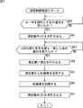
次に、図7のフローチャートを参照して、図6のスマートフォン22が行う測定制御処理について説明する。
[Description of operation of the
Next, the measurement control process performed by the
なお、図6のスマートフォン22は、図2のスマートフォン22と同様の報知処理を行う他、図2のスマートフォン22とは異なる処理として、測定制御処理を行う。
6 performs the measurement control process as a process different from the
ステップS61では、通信制御部101は、ユーザ識別部61からの、ユーザを識別した旨の通知が行なわれるのを待って、処理をステップS62に進める。
In step S61, the
ステップS62では、通信制御部101は、通信部102を介して、測定器21を制御し、測定器21のLED21bを点灯させる。
In step S <b> 62, the
すなわち、例えば、通信制御部101は、測定器21のLED21bの点灯を指示する点灯指示信号を、通信部102に供給する。そして、通信制御部101は、通信部102を制御して、点灯指示信号を、通信部102から測定器21に送信させる。
That is, for example, the
これにより、測定器21において、通信部21cは、通信部102からの点灯指示信号を受信する。そして、測定器21の図示せぬ制御部は、通信部21cで受信された点灯指示信号に基づいて、LED21bを制御して点灯させる。
Thereby, in the measuring
ステップS63では、通信制御部101は、判定部63からの、LED位置と測定位置が一致した旨の通知が行われるのを待って、処理をステップS64に進める。
In step S63, the
ステップS64では、通信制御部101は、通信部102を介して、測定器21を制御し、例えば肌画像の測定を行わせる。
In step S <b> 64, the
すなわち、例えば、通信制御部101は、測定器21に測定を指示する測定指示信号を、通信部102に供給する。そして、通信制御部101は、通信部102を制御して、測定指示信号を、通信部102から測定器21に送信させる。
That is, for example, the
これにより、測定器21において、通信部21cは、通信部102からの測定指示信号を受信する。そして、測定器21の図示せぬ制御部は、通信部21cで受信された測定指示信号に基づいて、カメラ21aを制御してユーザの肌の撮像を行わせ、その撮像により得られる肌画像を、通信部21cを介して、通信部102に送信させる。
Thereby, in the measuring
ステップS65では、通信部102は、測定器21の通信部21cからの肌画像を受信し、通信制御部101に供給する。
In step S <b> 65, the
ステップS66では、通信制御部101は、通信部102からの肌画像を、判定部63からのLED位置に対応付けて、例えばデータ記憶部103に記憶する。なお、判定部63から通信制御部101には、位置算出部62から出力されるLED位置が供給される。
In step S <b> 66, the
ここで、データ記憶部103に記憶された肌画像は、例えば、ユーザの肌の状態を判別するための解析ソフト等により解析される。そして、その解析結果は、例えばLCD22bに表示させることができる。
Here, the skin image stored in the data storage unit 103 is analyzed by, for example, analysis software or the like for determining the state of the user's skin. The analysis result can be displayed on the
ステップS67では、通信制御部101は、通信部102を介して、測定器21を制御し、測定器21のLED21bを消灯させる。
In step S67, the
すなわち、例えば、通信制御部101は、測定器21のLED21bの消灯を指示する消灯指示信号を、通信部102に供給する。そして、通信制御部101は、通信部102を制御して、消灯指示信号を、通信部102から測定器21に送信させる。
That is, for example, the
これにより、測定器21において、通信部21cは、通信部102からの消灯指示信号を受信する。そして、測定器21の図示せぬ制御部は、通信部21cで受信された消灯指示信号に基づいて、LED21bを制御して消灯させる。以上で測定制御処理は終了される。
Thereby, in the measuring
以上説明したように、測定制御処理によれば、通信制御部101は、LED位置が測定位置と一致した場合、通信部102を介して、測定器21を制御し、測定器21に肌画像の測定を行わせるようにした。
As described above, according to the measurement control process, when the LED position matches the measurement position, the
このため、ユーザは、測定器21に測定を行わせるための測定ボタン(図示せず)を押下する手間を省くことができ、測定器21に、ユーザの顔の同じ箇所から、肌データとしての例えば肌画像を、繰り返し測定させることができる。
For this reason, the user can save the trouble of pressing down a measurement button (not shown) for causing the measuring
測定器21は、測定位置と一致するLED位置で、肌データの測定を行うようにした。しかしながら、測定器21は、例えば、ユーザの肌に接近された状態で移動しながら、複数の異なる測定位置毎に、肌データの測定を行うようにすることができる。
The measuring
すなわち、例えば、測定器21において、内蔵のカメラ21aは、複数の異なる測定位置毎に撮像を行うことにより、肌データとしての複数の肌画像を測定することができる。
That is, for example, in the measuring
次に、図8は、測定器21が、ユーザの肌に接近された状態で移動しながら、複数の異なる測定位置毎に、肌画像の測定を行うときの様子の一例を示している。
Next, FIG. 8 shows an example of a state in which the measuring
なお、図8Aにおいて、測定領域121は、測定器21により測定される領域を表し、肌画像121a乃至121iは、測定領域121を対象とした測定により得られる肌画像の一例を表している。
In FIG. 8A, a
また、図8Aにおいて、軌跡21b'は、測定領域121内において、測定器21の測定時に、LED21bが移動した軌跡を表している。
In FIG. 8A, a
さらに、図8Bにおいて、全体肌画像121'は、測定領域121を撮像したときに得られる画像を表している。この全体肌画像121'は、例えば、図8Aに示される肌画像121a乃至121iをそれぞれつなぎ合わせることにより生成される。
Further, in FIG. 8B, the
ユーザは、LED21bが軌跡21b'を描くように、測定器21を移動させる。この場合、測定器21は、例えば、図6のスマートフォン22からの制御に従って、軌跡21b'上の各測定位置で肌画像121a乃至121iの測定を行う。また、図6のスマートフォン22において、出力制御部64は、スピーカ65を制御して、軌跡21b'上の各測定位置で、電子音を出力させるようにしてもよい。
The user moves the measuring
なお、図8では、ユーザは、LED21bが軌跡21b'を描くように、測定器21を移動させるものとした。しかし、軌跡21b'は、これに限定されず、測定器21が、肌画像121a乃至121iを測定可能な軌跡であればよく、過去の測定時の軌跡と同一である必要はない。すなわち、軌跡21b'の開始位置や終了位置等は、過去の測定時の軌跡と異なっていてもよい。
In FIG. 8, the user moves the measuring
測定器21は、測定により得られた肌画像121a乃至121iを、図6のスマートフォン22に送信する。
The measuring
図6のスマートフォン22は、測定器21からの肌画像121a乃至121iを受信し、受信した肌画像121a乃至121iに基づいて、図8Bに示されるような全体肌画像121'を生成する。
The
[全体肌画像を生成するときの図6のスマートフォン22の動作説明]
次に、図9のフローチャートを参照して、図6のスマートフォン22が、肌画像121a乃至121iを合成して全体肌画像121'を生成する画像合成処理を説明する。
[Description of Operation of
Next, an image composition process in which the
ステップS81乃至ステップS86では、図7のステップS61乃至ステップS66と同様の処理が行われる。 In steps S81 to S86, processing similar to that in steps S61 to S66 in FIG. 7 is performed.
ステップS87では、通信制御部101は、例えば、データ記憶部103に保持済みの肌画像に対応付けられたLED位置に基づいて、軌跡21b'上の各測定位置で得られる肌画像の全てが測定されたか否かを判定する。
In step S87, the
そして、ステップS87では、通信制御部101は、データ記憶部103に保持済みの肌画像に対応付けられたLED位置に基づいて、軌跡21b'上の各測定位置で得られる肌画像の全てがまだ測定されていないと判定した場合、処理をステップS83に戻す。
In step S87, the
ステップS83では、通信制御部101は、LED位置が、軌跡21b'上の各測定位置のうち、肌画像の測定がまだ行われていない測定位置と一致した旨の通知を、判定部63から受けたか否かを判定する。
In step S83, the
そして、通信制御部101は、判定部63からの通知を受けたと判定するまで、ステップS83の処理を繰り返し、判定部63からの通知を受けたと判定した場合、処理をステップS84に進め、それ以降、同様の処理が行われる。
The
また、ステップS87では、通信制御部101は、データ記憶部103に保持済みの肌画像に対応付けられたLED位置に基づいて、軌跡21b'上の各測定位置で得られる肌画像の全てが測定されたと判定した場合、処理をステップS88に進める。
In step S87, the
ステップS88では、通信制御部101は、ステップS83乃至ステップS87の処理を繰り返すことにより、データ記憶部103に記憶された肌画像121a乃至121iを、データ記憶部103から読み出す。
In step S88, the
そして、通信制御部101は、読み出した肌画像121a乃至121iに基づいて、測定領域121に対応する全体肌画像121'を生成し、データ記憶部103に供給して記憶させる。
And the
ステップS89では、図7のステップS67と同様の処理が行われ、画像合成処理は終了する。 In step S89, processing similar to that in step S67 in FIG. 7 is performed, and the image composition processing ends.
以上説明したように、画像合成処理によれば、通信制御部101は、軌跡21b'上の各測定位置で得られた肌画像121a乃至121iに基づいて、測定領域121に対応する全体肌画像121'を生成するようにした。
As described above, according to the image composition processing, the
このため、画像合成処理によれば、図6のスマートフォン22は、1回の測定では取得できない、測定領域121に対応する全体肌画像121'も取得することが可能となる。
For this reason, according to the image composition processing, the
また例えば、図6のスマートフォン22において、撮像部22aからの撮像画像に基づいて、測定位置までの距離を測定する距離測定部を設けるようにすれば、肌画像121a乃至121iそれぞれの奥行き方向の位置(奥行き情報)も得ることができる。
In addition, for example, in the
この場合、図6のスマートフォン22は、肌画像121a乃至121iと奥行き情報に基づいて、奥行き情報を有する3次元画像としての全体肌画像121'を生成することができる。
In this case, the
すなわち、例えば、図6のスマートフォン22は、2次元位置としての測定位置と、奥行き方向の位置としての奥行き情報により、肌画像121a乃至121iそれぞれの3次元位置を算出できる。
That is, for example, the
このため、図6のスマートフォン22は、算出した肌画像121a乃至121iそれぞれの3次元位置に、対応する肌画像をマッピングすることにより、立体的な全体肌画像121'を生成して、例えばLCD22bに表示させることができる。
For this reason, the
なお、距離測定部は、例えば、撮像部22aから出力される撮像画像内のLED21bの明るさ(輝度)や大きさに応じて、距離を測定することができる。これは、測定器21のLED21bが、図6のスマートフォン22に近い程に、撮像画像内において、LED21bは、高輝度となるとともに大きく表示されることを利用している。
The distance measuring unit can measure the distance according to the brightness (luminance) and size of the
また、距離測定部としては、例えば、撮像画像の各画素に表示されたものまでの距離をそれぞれ表す距離画像を生成する距離画像生成部を採用することができる。 In addition, as the distance measurement unit, for example, a distance image generation unit that generates a distance image that represents a distance to what is displayed on each pixel of the captured image can be employed.
距離画像生成部は、例えば、視差が設けられた複数のカメラを用いるステレオカメラ法や、カメラとレーザスリット光を用いた光切断法等により、距離画像を生成する。 The distance image generation unit generates a distance image by, for example, a stereo camera method using a plurality of cameras provided with parallax or a light cutting method using a camera and laser slit light.
また例えば、距離画像生成部は、Time of Flightカメラや、Time of Flightカメラと同様の原理で距離を測定するレーザレンジファインダを用いて、距離画像を生成するようにしてもよい。 Further, for example, the distance image generation unit may generate a distance image using a time of flight camera or a laser range finder that measures a distance based on the same principle as that of the time of flight camera.
ここで、Time of Flightカメラとは、光を照射する光源部を有し、光源部からの光が反射して受光されるまでの光の飛行時間(Time of Flight)と、光の速さに基づいて、距離を測定するカメラをいう。 Here, the Time of Flight camera has a light source unit that emits light, and the time of flight until the light from the light source unit is reflected and received and the speed of light. A camera that measures distance based on it.
<4.変形例>
[測定器21の変形例]
測定器21は、肌データの測定として、内蔵のカメラ21aを用いた肌画像の撮像を行うようにした。
<4. Modification>
[Modification of measuring instrument 21]
The measuring
しかしながら、測定器21において、異なる波長の光を照射する照射部を設けるようにし、照射部が、順次、異なる波長の光を肌に照射するようにしてもよい。そして、カメラ21aは、異なる波長の光が照射される毎に、肌の撮像を行うようにしてもよい。
However, the measuring
この場合、測定器21は、カメラ21aを用いることにより、波長毎に異なる肌画像として、肌の表皮が写った肌画像や、肌の真皮が写った肌画像、肌の血管が写った肌画像等を測定することとなる。
In this case, by using the
これは、肌を構成する表皮、真皮、及び血管等において、光の反射率が、波長毎に異なることによる。すなわち、例えば、肌の表皮の反射率が高く、肌の真皮や血管等の反射率が低い波長の光を照射部が照射すれば、測定器21は、カメラ21aの撮像により、肌の表皮(のみ)が写った肌画像を測定することができる。
This is due to the fact that the reflectance of light differs for each wavelength in the epidermis, dermis, blood vessels and the like constituting the skin. That is, for example, if the irradiation unit irradiates light having a wavelength with high reflectance of the skin epidermis and low reflectance of the skin dermis or blood vessels, the measuring
このため、測定器21では、肌の様々な状態を判別するための複数の肌画像を測定することができるようになる。
For this reason, the measuring
なお、測定器21に照射部を設ける場合、肌画像の測定方法として、例えば、照射部とカメラ21aを順番に駆動させる第1の測定方法と、照射部とカメラ21aを並行して駆動させる第2の測定方法が考えられる。
In addition, when providing the irradiation part in the measuring
すなわち、例えば、第1の測定方法では、照射部が、第1の波長の光を照射し、カメラ21aが、第1の波長の光が照射されている肌の撮像を行う。
That is, for example, in the first measurement method, the irradiating unit irradiates light of the first wavelength, and the
次に、照射部は、第1の波長の光の照射を終了した後、第1の波長とは異なる第2の波長の光を照射し、カメラ21aは、第2の波長の光が照射されている肌の撮像を行う。
Next, after irradiating the light of the first wavelength, the irradiation unit irradiates light of a second wavelength different from the first wavelength, and the
これにより、カメラ21aは、第1の波長の光が照射されている肌の肌画像と、第2の波長の光が照射されている肌の肌画像を得ることができる。
Thereby, the
なお、測定器21が測定領域121を測定する場合、カメラ21aが、測定領域121内の肌画像121a乃至121iの撮像を終了するまでの間、照射部は第1の波長の光を照射し続けることとなる。
When the measuring
また、カメラ21aが、肌画像121a乃至121iを撮像し終えた後、照射部は、第1の波長の光の照射を終了し、第2の波長の光の照射を開始する。そして、カメラ21aが、測定領域121内の肌画像121a乃至121iの撮像を終了するまでの間、照射部は第2の波長の光を照射し続けることとなる。
In addition, after the
これにより、カメラ21aは、第1の波長の光が照射されている肌の肌画像121a乃至121iと、第2の波長の光が照射されている肌の肌画像121a乃至121iを得ることができる。
Thereby, the
また、例えば、第2の測定方法では、照射部が、順次、異なる波長の光を肌に照射する。このとき、カメラ21aは、照射部による照射と並行して撮像を行う。
Further, for example, in the second measurement method, the irradiation unit sequentially irradiates the skin with light of different wavelengths. At this time, the
これにより、カメラ21aは、異なる波長毎の肌画像を、それぞれ取得することができる。
Thereby, the
なお、測定器21が測定領域121を測定する場合、異なる波長毎に、肌画像121a乃至121iが得られる速さで、ユーザは、測定器21を移動させる必要がある。
When the measuring
このため、例えば、スマートフォン22は、ユーザによる測定器21の移動が速すぎる場合、その旨をユーザに報知して、測定器21の速さを調整させるようにすることが望ましい。なお、ユーザへの報知には、スピーカ65やLCD22bが用いられる。
For this reason, for example, when the movement of the measuring
また、測定器21の速さは、LED位置の変化、又は測定器21の動きに関する動き情報の少なくとも一方に基づき、スマートフォン22により算出される。
Further, the speed of the measuring
ここで、動き情報としては、測定器21の加速度や角速度等を採用することができる。なお、スマートフォン22が、測定器21の加速度や角速度等に基づいて、測定器21の速さを識別する場合、測定器21には、測定器21の加速度や角速度等をセンシングする各種のセンサ(例えば、加速度センサや角速度センサ(ジャイロセンサ))が設けられる。
Here, as the motion information, the acceleration or angular velocity of the measuring
そして、測定器21は、適宜、各種のセンサから得られるセンシング結果を、スマートフォン22に送信する。スマートフォン22は、測定器21からのセンシング結果に基づいて、測定器21の速さを識別し、識別した速さが、所定の速さ以上である場合に、測定器21の移動が速すぎる旨等を、LCD22bに表示するなどして、ユーザに報知する。
Then, the measuring
また、スマートフォン22は、測定器21からのセンシング結果に基づいて、測定器21(カメラ21a)の傾き(撮像方向)を識別できる。
The
このため、スマートフォン22は、カメラ21aの傾きが、現在のLED位置に応じた傾き(例えば、カメラ21aの光軸が、肌の表面と垂直に交わるときの傾き)となっているか否かを判定することができる。
For this reason, the
そして、スマートフォン22は、カメラ21aの傾きが、LED位置に応じた傾きとなっていないと判定した場合、カメラ21aの傾きを、LED位置に応じた傾きに修正することを指示する旨を、LCD22b等に表示することにより、ユーザに報知することができる。
When the
よって、ユーザは、スマートフォン22のLCD22bを参照しながら、カメラ21aの傾きを、LED位置に応じた傾きに修正できるので、肌画像の撮像に失敗する事態を防止することが可能となる。
Therefore, since the user can correct the tilt of the
なお、上述のように、スマートフォン22は、測定器21からのセンシング結果に基づき、カメラ21aの傾きを識別するようにしたが、撮像部22aから出力される撮像画像に基づいて、カメラ21aの傾きを識別するようにしてもよい。
As described above, the
この場合、測定器21の筐体には、LED21bに代えて、2次元バーコード等の図形が、マーカとして設けられているものとする。そして、スマートフォン22は、撮像部22aから出力される撮像画像内の図形の形状(例えば、図形の歪み等)に基づいて、カメラ21aの傾きを識別する。
In this case, it is assumed that a figure such as a two-dimensional barcode is provided as a marker in the housing of the measuring
なお、測定器21に設けられるマーカは、2次元バーコード等の図形に限定されず、カメラ21aの傾きを識別するためのマーカであれば、どのようなマーカを採用してもよい。すなわち、例えば、2次元バーコード等の図形に代えて、測定器21の上下左右にそれぞれLEDを設けるようにしてもよい。
The marker provided in the measuring
また、スマートフォン22は、測定器21からのセンシング結果と、撮像部22aから出力される撮像画像内の図形の形状の両方に基づいて、カメラ21aの傾きを識別するようにしてもよい。この場合、スマートフォン22は、カメラ21aの傾きを、より精度良く識別することができる。
The
次に、図10乃至図14を参照して、測定器21の他の一例について説明する。
Next, another example of the measuring
図10は、スマートフォン22に着脱自在とされたジャケット型の測定器21'の一例を示している。
FIG. 10 shows an example of a jacket-
この測定器21'は、例えば、図10に示されるように、スマートフォン22の側面を覆うようにして、スマートフォン22に装着可能な形状を有する。なお、測定器21'の形状は、図10に示される形状に限定されず、スマートフォン22に着脱自在であれば、どのような形状であってもよい。
For example, as shown in FIG. 10, the measuring
また、測定器21'には、カメラ21a、LED21b、通信部21c、及び充電用コネクタ21dが設けられている。なお、カメラ21a乃至通信部21cは、図6のカメラ21a乃至通信部21cと同様に構成されているため、同一の符号を付すようにして説明を省略している。
The measuring
充電用コネクタ21dは、測定器21'に内蔵された図示せぬバッテリの充電用に設けられたコネクタである。
The charging
測定器21'は、例えば、図10に示されるような、スマートフォン22から取り外された状態で、図1に示した測定器21と同様にして、ユーザの肌データを測定する。
The measuring
なお、スマートフォン22では、測定器21'が取り外されたことに対応して、図3の報知処理や、図5の状態表示処理、図7の測定制御処理、図9の画像合成処理等を行うためのアプリケーションを起動するように構成することができる。
Note that the
次に、図11は、測定器21'が、スマートフォン22に装着されたときの一例を示している。
Next, FIG. 11 shows an example when the measuring
測定器21'がスマートフォン22に取り付けられたとき、測定器21'の充電用コネクタ21dは、図11に示されるように、スマートフォン22の給電用コネクタ22cと物理的に接続される。
When the measuring
給電用コネクタ22cは、測定器21'への給電用に設けられたコネクタであり、物理的に接続された充電用コネクタ21dに、スマートフォン22の図示せぬ給電部からの電力を供給する。
The power supply connector 22c is a connector provided for power supply to the measuring instrument 21 ', and supplies power from a power supply unit (not shown) of the
なお、スマートフォン22において、図示せぬ給電部は、スマートフォン22の図示せぬバッテリから電力、又はスマートフォン22の充電に用いる充電器からの電力の少なくとも一方を、給電用コネクタ22cに供給する。
Note that, in the
充電用コネクタ21dは、給電用コネクタ22cからの電力を、測定器21'の図示せぬ内蔵のバッテリに供給して充電を行う。
The charging
図11に示されるように、スマートフォン22に着脱自在なジャケット型の測定器21'を採用する場合、スマートフォン22を携帯して外出すれば、必然的に測定器21'も持ち出すこととなるので、測定器21'を家等に忘れる事態等を防止することが可能となる。
As shown in FIG. 11, when the jacket-
このため、ユーザは、外出先などでも、測定器21'を用いて、肌の定点観測を行うことができる。
For this reason, the user can perform fixed point observation of the skin using the measuring
さらに、測定器21'は、スマートフォン22に取り付けられ、スマートフォン22と一体的に構成されるため、比較的、煩わしさを感じることなく、測定器21'及びスマートフォン22を持ち出すことができる。
Furthermore, since the measuring
また、スマートフォン22は、電子メールの送受信や電話の使用の他、肌の測定時にも用いられる。このため、ユーザは、スマートフォン22とは別に、ユーザとLED21bを撮像して得られる撮像画像を表示する専用の表示装置等を、外出先に持っていく必要がない。
The
さらに測定器21'は、スマートフォン22に取り付けられている場合、スマートフォン22の図示せぬ内蔵の給電部により、測定器21'の充電が行われることとなるので、外出先で、測定器21'がバッテリ切れとなる事態を抑止することができる。
Furthermore, when the measuring
このため、ユーザは、測定器21'のバッテリ切れにより、肌データの測定ができなくなる事態を抑止することが可能となる。 For this reason, it becomes possible for the user to suppress a situation in which skin data cannot be measured due to the battery of the measuring instrument 21 'being exhausted.
なお、ユーザは、測定器21'による肌データの測定時に、鏡を用いるようにすれば、スマートフォン22に測定器21'が装着された状態でも、肌データの定点観測を行うことができる。
In addition, if a user uses a mirror at the time of the measurement of skin data by measuring device 21 ', he can perform fixed point observation of skin data even in the state where measuring device 21' is attached to
次に、図12は、ジャケット型の測定器21'がスマートフォン22に装着された状態で、測定器21'に肌データの測定を行わせるときの一例を示している。
Next, FIG. 12 shows an example when the skin data is measured by the measuring
ユーザは、測定器21'をスマートフォン22に装着した状態で、測定器21'に測定を行わせる場合、図12に示されるように、鏡に映るLCD22bの表示内容を参照しながら、測定器21'を、顔に接近させた状態で移動させる。
When the user causes the
これにより、ユーザは、図1の測定システム1の場合と同様に、スマートフォン22のLCD22bに表示される表示内容(例えば、撮像部22aの撮像により得られる撮像画像等)を、目の前の鏡を介して参照することができる。
Thereby, the user can display the display content (for example, the captured image obtained by the imaging of the
また、スマートフォン22において、内蔵の撮像部22aは、鏡に映る被写体としてのユーザとともに、同じく鏡に映る測定器21'のLED21bを撮像することにより、図1の場合と同様の撮像画像を得ることができる。
In addition, in the
なお、カメラ21aとLED21bの位置が、図12に示した測定器21'とは逆になるような他の測定器の場合でも、カメラ21aとLED21bの位置を、図12に示したような位置に変更可能な駆動部を設けるようにすればよい。
Even in the case of another measuring device in which the positions of the
この場合、他の測定器は、スマートフォン22に装着されたままで、肌の測定を行うことができる。
In this case, other measuring devices can measure the skin while being attached to the
なお、スマートフォン22に、測定器21を一体不可分に設けるようにした場合でも、そのようなスマートフォン22を用いて、図12を参照して説明したように、肌の測定を行うことができる。
Even when the measuring
また、スマートフォン22は、測定器21'が装着された状態で、肌データの測定の用途の他、別の用途に用いることができる。
Moreover, the
[拡大鏡として用いるときの一例]
次に、図13は、測定器21'及びスマートフォン22を、拡大鏡として用いるようにしたときの一例を示している。
[Example when used as a magnifying glass]
Next, FIG. 13 shows an example when the measuring
図13には、文字列「あいうえおかきくけこさしすせそ」のうち、文字列「こさし」を拡大してLCD22bに表示中のスマートフォン22が示されている。
FIG. 13 shows the
なお、図13には、文字列「あいうえおかきくけこさしすせそ」のうち、文字列「あいうえおか」のみが記載され、残りの文字列「きくけこさしすせそ」は、測定器21'及びスマートフォン22に隠れた状態となっている。
In FIG. 13, only the character string “Aiueoka” is described in the character string “Aiueokaki Kessashisoseso”, and the remaining character string “Kikukokesashisoseso” is stored in the measuring
図13において、測定器21'は、内蔵されたカメラ21aを用いて、文字列「こさし」が記載された部分を接写する撮像を行い、その撮像により得られる撮像画像を、スマートフォン22に供給する。
In FIG. 13, the measuring
そして、スマートフォン22は、測定器21'からの撮像画像を拡大し、拡大後の撮像画像を、LCD22bに表示する。
Then, the
このため、測定器21'及びスマートフォン22は、図12に示されるように、拡大鏡としても用いることができる。
For this reason, measuring instrument 21 'and
なお、測定器21'は、スマートフォン22から取り外された状態でも、測定器21'及びスマートフォン22を、拡大鏡として用いることができる。この場合、測定器21'は、内蔵のカメラ21aの撮像で得られた画像を、無線通信等により、スマートフォン22に送信することなる。
Note that the measuring
また、例えば、スマートフォン22は、測定器21'が装着されている場合、拡大鏡として機能するためのアプリケーションを実行し、測定器21'が取り外された場合、肌の測定を行うためのアプリケーションを実行するようにしてもよい。
In addition, for example, the
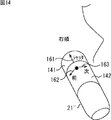
次に、図14は、より操作性を向上させた測定器21"の一例を示している。
Next, FIG. 14 shows an example of a measuring
この測定器21"は、例えば、図14に示されるように、円筒形の形状とされ、鏡筒部141及びモード切替部142を有する。なお、測定器21"には、測定器21等と同様に、カメラ21a及びLED21b等が設けられるが、図面が煩雑になるのを避けるために、それらの図示は省略している。
For example, as shown in FIG. 14, the measuring
鏡筒部141は、例えば、カメラ21aの光学系等を囲む筒状の部分であり、オフ状態又はオン状態のいずれかとされる。また、鏡筒部141は、カメラ21aで撮像される肌により押下され、オフ状態からオン状態とされる。
The
すなわち、例えば、測定器21"が、図14に示される矢印161の方向に押し当てられた場合、測定器21"の鏡筒部141は、ユーザの顔の箇所(例えば、図14では右頬)に押下され、オン状態とされる。
That is, for example, when the measuring
この場合、例えば、カメラ21aは、鏡筒部141がオン状態とされたことに対応して、測定器21"を押し当てた肌(例えば、図14では右頬)の撮像を行う。すなわち、例えば、鏡筒部141は、カメラ21aのシャッタボタンとして機能し、カメラ21aの撮像時に、オフ状態からオン状態とされる。
In this case, for example, the
ここで、矢印161の方向と、カメラ21aの撮像方向(光軸)は、同方向であるため、カメラ21aの撮像時の撮像振れが(殆ど)発生しない。
Here, since the direction of the
したがって、測定器21"によれば、カメラ21aにより、ブレのない鮮明な肌画像を撮像することが可能となる。
Therefore, according to the measuring
モード切替部142は、カメラ21aの光軸を中心として、図14に示される矢印162及び矢印163の方向に、それぞれ回転自在に構成されており、測定器21"による各種の動作モードを切り替える際に操作される。
The
すなわち、例えば、モード切替部142が、矢印162の方向に回転されると、測定器21"の動作モードは、前の動作モードに切り替えられる。また、例えば、モード切替部142が、矢印163の方向に回転されると、測定器21"の動作モードは、次の動作モードに切り替えられる。
That is, for example, when the
具体的には、例えば、第1の動作モード、第2の動作モード、及び第3の動作モードが存在し、測定器21"の動作モードが第2の動作モードである場合、ユーザの切替操作に応じて、動作モードは、以下のようにして切り替えられる。
Specifically, for example, when there is a first operation mode, a second operation mode, and a third operation mode, and the operation mode of the measuring
つまり、ユーザは、モード切替部142を矢印162の方向に回転させるだけで、測定器21"の動作モードを、第2の動作モードから、第1の動作モードに切り替えることができる。
That is, the user can switch the operation mode of the measuring
また、例えば、ユーザは、モード切替部142を矢印163の方向に回転させるだけで、測定器21"の動作モードを、第2の動作モードから、第3の動作モードに切り替えることができる。
Further, for example, the user can switch the operation mode of the measuring
このため、例えば、ユーザは、スマートフォン22を操作して、測定器21"の動作モードを切り替える場合と比較して、煩わしさを感じることなく、容易に動作モードを切り替えることが可能となる。
For this reason, for example, the user can easily switch the operation mode without feeling inconvenience as compared with the case of operating the
また、例えば、ユーザは、スマートフォン22を操作することなく、測定器21"の動作モードを切り替えることができるので、スマートフォン22の操作に気をとられて、測定器21"を落としてしまう事態を防止できる。
In addition, for example, since the user can switch the operation mode of the measuring
なお、測定器21"の動作モードとしては、例えば、左頬の肌を測定する際の動作モードや、右頬の肌を測定する際の動作モードなどを採用することができる。
As an operation mode of the measuring
また、例えば、測定器21"は、スマートフォン22のソフトウェアと連携すれば、ユーザからの操作に応じて、スマートフォン22のLCD22bに表示された項目の選択や決定を行うことができる。
Further, for example, if the measuring
すなわち、例えば、測定器21"において、ユーザが、モード切替部142を矢印162の方向に回転させると、カーソル等により、前の項目が選択される。また、例えば、ユーザが、モード切替部142を矢印163の方向に回転させると、カーソル等により、次の項目が選択される。
That is, for example, in the measuring
そして、ユーザが、矢印161の方向に測定器21"を押し当てると、測定器21"の鏡筒部141が押下される。これにより、スマートフォン22において、カーソル等で選択されている項目に対する決定が行われ、決定された項目に対応する表示が、LCD22bに表示される。
When the user presses the measuring
なお、図1の測定システム1において、例えば、スマートフォン22のLCD22bは、撮像部22aの撮像により得られる撮像画像を表示するようにした。
In the
しかしながら、LCD22bには、例えば、撮像画像とともに、測定器21が内蔵するカメラ21aから得られる肌画像を、構図決定用のスルー画として表示するようにしてもよい。
However, on the
この場合、測定器21は、無線通信等を用いて、カメラ21aから得られる肌画像を、スルー画として、スマートフォン22に供給しているものとする。このことは、図1において、測定器21に代えて、測定器21'や測定器21"を用いる場合についても同様である。
In this case, it is assumed that the measuring
また例えば、測定システム1は、測定器21とスマートフォン22から構成されるようにしたが、スマートフォン22に代えて、タブレット端末やパーソナルコンピュータ等を採用することができる。
Further, for example, the
ところで、本技術は、以下の構成をとることができる。
(1)接近した状態で被写体の一部を測定する測定器に設けられたマーカを、前記被写体とともに撮像する撮像部と、
前記撮像部による撮像で得られる撮像画像に基づいて、前記被写体に対する前記マーカの位置を表すマーカ位置を算出する位置算出部と、
前記マーカ位置が、前記被写体の一部を測定するときのマーカ位置である測定位置と一致した場合、予め決められた制御処理を行う制御部と
を含む情報処理装置。
(2)前記マーカは、点灯又は消灯することにより、予め決められた点滅パターンで点滅する発光部であり、
前記撮像画像内の前記マーカの点灯又は消灯に基づいて、前記マーカの点滅パターンを検知するパターン検知部を
さらに含む前記(1)に記載の情報処理装置。
(3)前記マーカは、前記測定器の状態を表す前記点滅パターンで点滅し、
前記パターン検知部の検知結果に基づいて、前記測定器の状態を表示部に表示させる表示制御部を
さらに含む前記(2)に記載の情報処理装置。
(4)前記制御部は、前記マーカ位置が、前記測定器が移動する軌跡上の各測定位置と一致する毎に、予め決められた制御処理を行う
前記(1)乃至(3)に記載の情報処理装置。
(5)前記制御部は、前記マーカ位置が前記測定位置と一致した場合、その旨をユーザに報知させる第1の前記制御処理、又は前記測定器を制御して、前記測定器に前記被写体の一部を測定させる第2の前記制御処理の少なくとも一方を行う
前記(1)乃至(4)に記載の情報処理装置。
(6)前記測定器の傾きを識別する傾き識別部を
さらに含む前記(1)乃至(5)に記載の情報処理装置。
(7)前記測定器は、前記測定器の動きをセンシングするセンサを有し、
前記傾き識別部は、前記センサのセンシング結果に基づいて、前記測定器の傾きを識別する
前記(6)に記載の情報処理装置。
(8)前記マーカは、前記測定器の筐体に設けられた図形であり、
前記傾き識別部は、前記撮像画像内の前記図形の形状に基づいて、前記測定器の傾きを識別する
前記(6)に記載の情報処理装置。
(9)前記測定器は、接近した状態で撮像を行うことにより、前記被写体の肌を測定し、
前記測定器の撮像により得られた複数の肌画像に基づいて、前記複数の肌画像をつなぎ合わせた全体肌画像を生成する生成部を
さらに含む前記(1)乃至(5)に記載の情報処理装置。
(10)前記測定位置までの距離を測定する距離測定部と、
前記測定位置と前記距離に基づいて、前記肌画像の3次元位置を算出する3次元位置算出部と
をさらに含み、
前記生成部は、複数の前記肌画像の3次元位置にも基づいて、前記被写体の肌を立体的に表示する前記全体肌画像を生成する
をさらに含む前記(9)に記載の情報処理装置。
(11)前記測定器は、
前記被写体の一部に対して、複数の異なる波長の光を照射する照射部と、
複数の異なる波長毎に、前記波長の光が照射されているときの肌の撮像を行うことにより、前記被写体の一部を測定するカメラ測定部と
を有する
前記(1)乃至(5)に記載の情報処理装置。
(12)前記測定器は、前記情報処理装置に着脱自在とされる
前記1乃至5に記載の情報処理装置。
(13)前記測定器は、前記情報処理装置に装着された状態で充電可能とされる
前記(12)に記載の情報処理装置。
(14)前記測定器は、
前記被写体の一部を接写するカメラ測定部と、
前記カメラ測定部を囲む筒状の形状を有し、前記被写体の一部に押し当てられたときにオン状態とされる鏡筒部と、
ユーザの回転操作に応じて、前記カメラ測定部の光軸を中心として回転される回転部と
を有する前記(1)乃至(5)に記載の情報処理装置。
(15)前記カメラ測定部は、前記鏡筒部がオン状態とされたときに、前記被写体の一部を接写し、
前記回転部は、前記カメラ測定部の動作に関する動作モードを切り替える際に、前記カメラ測定部の光軸を中心として回転される
前記(14)に記載の情報処理装置。
(16)接近した状態で被写体の一部を測定する測定器に設けられたマーカを、前記被写体とともに撮像する撮像部を有する情報処理装置の情報処理方法において、
前記撮像部による撮像で得られる撮像画像に基づいて、前記被写体に対する前記マーカの位置を表すマーカ位置を算出する位置算出ステップと、
前記マーカ位置が、前記被写体の一部を測定するときのマーカ位置である測定位置と一致した場合、予め決められた制御処理を行う制御ステップと
を含む情報処理方法。
(17)接近した状態で被写体の一部を測定する測定器に設けられたマーカを、前記被写体とともに撮像する撮像部を有する情報処理装置のコンピュータを、
前記撮像部による撮像で得られる撮像画像に基づいて、前記被写体に対する前記マーカの位置を表すマーカ位置を算出する位置算出部と、
前記マーカ位置が、前記被写体の一部を測定するときのマーカ位置である測定位置と一致した場合、予め決められた制御処理を行う制御部と
して機能させるためのプログラム。
(18)ユーザに接近した状態で測定を行う測定器と、前記ユーザ及び前記測定器を撮像する撮像部を有する情報処理装置から構成される測定システムにおいて、
前記測定器は、
接近した状態でユーザの一部を測定する測定部と、
前記測定器の筐体に設けられたマーカと
を有し、
前記情報処理装置は、
前記測定器に設けられた前記マーカを、前記ユーザとともに撮像する撮像部と、
前記撮像部による撮像で得られる撮像画像に基づいて、前記ユーザに対する前記マーカの位置を表すマーカ位置を算出する位置算出部と、
前記マーカ位置が、前記ユーザの一部を測定するときのマーカ位置である測定位置と一致した場合、予め決められた制御処理を行う制御部と
を有する
測定システム。
By the way, this technique can take the following structures.
(1) an imaging unit that captures an image of a marker provided on a measuring instrument that measures a part of a subject in an approached state together with the subject;
A position calculation unit that calculates a marker position that represents the position of the marker with respect to the subject based on a captured image obtained by imaging by the imaging unit;
An information processing apparatus including: a control unit that performs a predetermined control process when the marker position matches a measurement position that is a marker position when measuring a part of the subject.
(2) The marker is a light emitting unit that blinks in a predetermined blinking pattern by turning on or off.
The information processing apparatus according to (1), further including a pattern detection unit that detects a blinking pattern of the marker based on lighting or extinguishing of the marker in the captured image.
(3) The marker blinks in the blinking pattern indicating the state of the measuring instrument,
The information processing apparatus according to (2), further including a display control unit configured to display a state of the measuring instrument on a display unit based on a detection result of the pattern detection unit.
(4) The control unit performs a predetermined control process every time the marker position coincides with each measurement position on a trajectory on which the measuring device moves. (1) to (3) Information processing device.
(5) When the marker position matches the measurement position, the control unit controls the first control process for informing the user of the fact, or the measurement device, and causes the measurement device to detect the subject. The information processing apparatus according to any one of (1) to (4), wherein at least one of the second control processes for measuring a part is performed.
(6) The information processing apparatus according to (1) to (5), further including an inclination identification unit that identifies an inclination of the measuring instrument.
(7) The measuring instrument has a sensor for sensing the movement of the measuring instrument,
The information processing apparatus according to (6), wherein the inclination identification unit identifies an inclination of the measuring device based on a sensing result of the sensor.
(8) The marker is a figure provided on a housing of the measuring device,
The information processing apparatus according to (6), wherein the inclination identification unit identifies an inclination of the measuring device based on a shape of the graphic in the captured image.
(9) The measuring device measures the skin of the subject by performing imaging in an approaching state,
The information processing according to any one of (1) to (5), further including a generation unit that generates an entire skin image obtained by connecting the plurality of skin images based on the plurality of skin images obtained by imaging by the measuring device. apparatus.
(10) a distance measuring unit that measures the distance to the measurement position;
A three-dimensional position calculation unit that calculates a three-dimensional position of the skin image based on the measurement position and the distance;
The information processing apparatus according to (9), wherein the generation unit further includes: generating the whole skin image that stereoscopically displays the skin of the subject based on three-dimensional positions of the plurality of skin images.
(11) The measuring instrument is
An irradiation unit that irradiates a part of the subject with light of a plurality of different wavelengths;
The camera measurement unit that measures a part of the subject by imaging the skin when light of the wavelength is irradiated for each of a plurality of different wavelengths. The above (1) to (5) Information processing device.
(12) The information processing apparatus according to any one of (1) to (5), wherein the measuring device is detachable from the information processing apparatus.
(13) The information processing apparatus according to (12), wherein the measuring device can be charged in a state of being mounted on the information processing apparatus.
(14) The measuring instrument
A camera measurement unit for taking a close-up of a part of the subject;
A cylindrical part surrounding the camera measurement part, which is turned on when pressed against a part of the subject; and
The information processing apparatus according to any one of (1) to (5), further including: a rotation unit that rotates about the optical axis of the camera measurement unit in accordance with a user's rotation operation.
(15) When the lens barrel is turned on, the camera measurement unit takes a close-up of a part of the subject,
The information processing apparatus according to (14), wherein the rotation unit is rotated about an optical axis of the camera measurement unit when switching an operation mode related to an operation of the camera measurement unit.
(16) In an information processing method of an information processing apparatus having an imaging unit that images a marker provided on a measuring instrument that measures a part of a subject in an approached state together with the subject,
A position calculating step for calculating a marker position representing a position of the marker with respect to the subject based on a captured image obtained by imaging by the imaging unit;
An information processing method comprising: a control step of performing a predetermined control process when the marker position matches a measurement position that is a marker position when measuring a part of the subject.
(17) A computer of an information processing apparatus having an image pickup unit that picks up an image of a marker provided on a measuring device that measures a part of a subject in an approaching state together with the subject
A position calculation unit that calculates a marker position that represents the position of the marker with respect to the subject based on a captured image obtained by imaging by the imaging unit;
A program for functioning as a control unit that performs a predetermined control process when the marker position matches a measurement position that is a marker position when measuring a part of the subject.
(18) In a measurement system including a measurement device that performs measurement in a state of approaching a user, and an information processing device that includes an imaging unit that images the user and the measurement device,
The measuring instrument is
A measuring unit for measuring a part of the user in a close state,
A marker provided on a housing of the measuring instrument,
The information processing apparatus includes:
An imaging unit that images the marker provided in the measuring device together with the user;
A position calculation unit that calculates a marker position representing the position of the marker with respect to the user based on a captured image obtained by imaging by the imaging unit;
A control system comprising: a control unit that performs a predetermined control process when the marker position coincides with a measurement position that is a marker position when measuring a part of the user.
上述した一連の処理は、例えばハードウェアにより実行することもできるし、ソフトウェアにより実行することもできる。一連の処理をソフトウェアにより実行する場合には、そのソフトウェアを構成するプログラムが、専用のハードウェアに組み込まれているコンピュータ、又は、各種のプログラムをインストールすることで、各種の機能を実行することが可能な、例えば汎用のコンピュータなどに、プログラム記録媒体からインストールされる。 The series of processes described above can be executed by hardware or software, for example. When a series of processing is executed by software, a program constituting the software may execute various functions by installing a computer incorporated in dedicated hardware or various programs. For example, it is installed from a program recording medium in a general-purpose computer or the like.
[コンピュータの構成例]
図15は、上述した一連の処理をプログラムにより実行するコンピュータのハードウェアの構成例を示している。
[Computer configuration example]
FIG. 15 shows an example of the hardware configuration of a computer that executes the above-described series of processing by a program.
CPU(Central Processing Unit)201は、ROM(Read Only Memory)202、又は記憶部208に記憶されているプログラムに従って各種の処理を実行する。RAM(Random Access Memory)203には、CPU201が実行するプログラムやデータ等が適宜記憶される。これらのCPU201、ROM202、及びRAM203は、バス204により相互に接続されている。
A CPU (Central Processing Unit) 201 executes various processes according to a program stored in a ROM (Read Only Memory) 202 or a
CPU201にはまた、バス204を介して入出力インタフェース205が接続されている。入出力インタフェース205には、キーボード、マウス、マイクロホン等よりなる入力部206、ディスプレイ、スピーカ等よりなる出力部207が接続されている。CPU201は、入力部206から入力される指令に対応して各種の処理を実行する。そして、CPU201は、処理の結果を出力部207に出力する。
An input /
入出力インタフェース205に接続されている記憶部208は、例えばハードディスクからなり、CPU201が実行するプログラムや各種のデータを記憶する。通信部209は、インタネットやローカルエリアネットワーク等のネットワークを介して外部の装置と通信する。
A
また、通信部209を介してプログラムを取得し、記憶部208に記憶してもよい。
Further, a program may be acquired via the
入出力インタフェース205に接続されているドライブ210は、磁気ディスク、光ディスク、光磁気ディスク、或いは半導体メモリ等のリムーバブルメディア211が装着されたとき、それらを駆動し、そこに記録されているプログラムやデータ等を取得する。取得されたプログラムやデータは、必要に応じて記憶部208に転送され、記憶される。
The
コンピュータにインストールされ、コンピュータによって実行可能な状態とされるプログラムを記録(記憶)する記録媒体は、図15に示すように、磁気ディスク(フレキシブルディスクを含む)、光ディスク(CD-ROM(Compact Disc-Read Only Memory),DVD(Digital Versatile Disc)を含む)、光磁気ディスク(MD(Mini-Disc)を含む)、もしくは半導体メモリ等よりなるパッケージメディアであるリムーバブルメディア211、又は、プログラムが一時的もしくは永続的に格納されるROM202や、記憶部208を構成するハードディスク等により構成される。記録媒体へのプログラムの記録は、必要に応じてルータ、モデム等のインタフェースである通信部209を介して、ローカルエリアネットワーク、インタネット、デジタル衛星放送といった、有線又は無線の通信媒体を利用して行われる。
As shown in FIG. 15, a recording medium for recording (storing) a program installed in a computer and ready to be executed by the computer includes a magnetic disk (including a flexible disk), an optical disk (CD-ROM (Compact Disc-
なお、本明細書において、上述した一連の処理を記述するステップは、記載された順序に沿って時系列的に行われる処理はもちろん、必ずしも時系列的に処理されなくとも、並列的あるいは個別に実行される処理をも含むものである。 In the present specification, the steps describing the series of processes described above are not limited to the processes performed in time series according to the described order, but are not necessarily performed in time series, either in parallel or individually. The process to be executed is also included.
また、本明細書において、システムとは、複数の装置により構成される装置全体を表すものである。 Further, in this specification, the system represents the entire apparatus constituted by a plurality of apparatuses.
さらに、本開示は、上述した実施の形態に限定されるものではなく、本開示の要旨を逸脱しない範囲において種々の変更が可能である。 Furthermore, the present disclosure is not limited to the above-described embodiments, and various modifications can be made without departing from the gist of the present disclosure.
1 測定システム, 21,21',21" 測定器, 21a カメラ, 21b LED, 21c 通信部, 21d 充電用コネクタ, 22 スマートフォン, 22a 撮像部, 22b LCD, 22c 給電用コネクタ, 41 光学系, 42 撮像素子, 43 信号処理IC, 61 ユーザ識別部, 62 位置算出部, 63 判定部, 63a メモリ, 64 出力制御部, 65 スピーカ, 66 表示制御部, 67 主制御部, 68 操作部, 81 パターン検知部, 82 状態識別部, 83 表示制御部, 101 通信制御部, 102 通信部, 103 データ記憶部, 141 鏡筒部, 142 モード切替部
1
Claims (18)
前記撮像部による撮像で得られる撮像画像に基づいて、前記被写体に対する前記マーカの位置を表すマーカ位置を算出する位置算出部と、
前記マーカ位置が、前記被写体の一部を測定するときのマーカ位置である測定位置と一致した場合、予め決められた制御処理を行う制御部と
を含む情報処理装置。 An imaging unit that captures an image of a marker provided on a measuring instrument that measures a part of the subject in an approaching state together with the subject;
A position calculation unit that calculates a marker position that represents the position of the marker with respect to the subject based on a captured image obtained by imaging by the imaging unit;
An information processing apparatus including: a control unit that performs a predetermined control process when the marker position matches a measurement position that is a marker position when measuring a part of the subject.
前記撮像画像内の前記マーカの点灯又は消灯に基づいて、前記マーカの点滅パターンを検知するパターン検知部を
さらに含む請求項1に記載の情報処理装置。 The marker is a light emitting unit that blinks in a predetermined blinking pattern by turning on or off.
The information processing apparatus according to claim 1, further comprising a pattern detection unit that detects a blinking pattern of the marker based on lighting or extinguishing of the marker in the captured image.
前記パターン検知部の検知結果に基づいて、前記測定器の状態を表示部に表示させる表示制御部を
さらに含む請求項2に記載の情報処理装置。 The marker blinks with the blink pattern representing the state of the measuring instrument,
The information processing apparatus according to claim 2, further comprising: a display control unit configured to display a state of the measuring instrument on a display unit based on a detection result of the pattern detection unit.
請求項1に記載の情報処理装置。 The information processing apparatus according to claim 1, wherein the control unit performs a predetermined control process every time the marker position matches each measurement position on a trajectory on which the measuring device moves.
請求項1に記載の情報処理装置。 When the marker position coincides with the measurement position, the control unit controls the first control process for informing the user of the fact, or the measurement device so that a part of the subject is placed on the measurement device. The information processing apparatus according to claim 1, wherein at least one of the second control processes to be measured is performed.
さらに含む請求項1に記載の情報処理装置。 The information processing apparatus according to claim 1, further comprising an inclination identification unit that identifies an inclination of the measuring instrument.
前記傾き識別部は、前記センサのセンシング結果に基づいて、前記測定器の傾きを識別する
請求項6に記載の情報処理装置。 The measuring instrument has a sensor for sensing the movement of the measuring instrument,
The information processing apparatus according to claim 6, wherein the inclination identification unit identifies an inclination of the measuring device based on a sensing result of the sensor.
前記傾き識別部は、前記撮像画像内の前記図形の形状に基づいて、前記測定器の傾きを識別する
請求項6に記載の情報処理装置。 The marker is a figure provided on the housing of the measuring device,
The information processing apparatus according to claim 6, wherein the inclination identification unit identifies an inclination of the measuring device based on a shape of the graphic in the captured image.
前記測定器の撮像により得られた複数の肌画像に基づいて、前記複数の肌画像をつなぎ合わせた全体肌画像を生成する生成部を
さらに含む請求項1に記載の情報処理装置。 The measuring device measures the skin of the subject by performing imaging in an approaching state,
The information processing apparatus according to claim 1, further comprising: a generation unit that generates an entire skin image obtained by connecting the plurality of skin images based on the plurality of skin images obtained by imaging by the measuring device.
前記測定位置と前記距離に基づいて、前記肌画像の3次元位置を算出する3次元位置算出部と
をさらに含み、
前記生成部は、複数の前記肌画像の3次元位置にも基づいて、前記被写体の肌を立体的に表示する前記全体肌画像を生成する
をさらに含む請求項9に記載の情報処理装置。 A distance measuring unit for measuring a distance to the measurement position;
A three-dimensional position calculation unit that calculates a three-dimensional position of the skin image based on the measurement position and the distance;
The information processing apparatus according to claim 9, wherein the generation unit further includes: generating the whole skin image that stereoscopically displays the skin of the subject based on a three-dimensional position of the plurality of skin images.
前記被写体の一部に対して、複数の異なる波長の光を照射する照射部と、
複数の異なる波長毎に、前記波長の光が照射されているときの肌の撮像を行うことにより、前記被写体の一部を測定するカメラ測定部と
を有する
請求項1に記載の情報処理装置。 The measuring instrument is
An irradiation unit that irradiates a part of the subject with light of a plurality of different wavelengths;
The information processing apparatus according to claim 1, further comprising: a camera measurement unit that measures a part of the subject by imaging the skin when light having the wavelength is irradiated for each of a plurality of different wavelengths.
請求項1に記載の情報処理装置。 The information processing apparatus according to claim 1, wherein the measuring instrument is detachable from the information processing apparatus.
請求項12に記載の情報処理装置。 The information processing apparatus according to claim 12, wherein the measuring device can be charged while being attached to the information processing apparatus.
前記被写体の一部を接写するカメラ測定部と、
前記カメラ測定部を囲む筒状の形状を有し、前記被写体の一部に押し当てられたときにオン状態とされる鏡筒部と、
ユーザの回転操作に応じて、前記カメラ測定部の光軸を中心として回転される回転部と
を有する請求項1に記載の情報処理装置。 The measuring instrument is
A camera measurement unit for taking a close-up of a part of the subject;
A cylindrical part surrounding the camera measurement part, which is turned on when pressed against a part of the subject; and
The information processing apparatus according to claim 1, further comprising: a rotation unit that is rotated about an optical axis of the camera measurement unit in accordance with a user's rotation operation.
前記回転部は、前記カメラ測定部の動作に関する動作モードを切り替える際に、前記カメラ測定部の光軸を中心として回転される
請求項14に記載の情報処理装置。 The camera measurement unit close-ups a part of the subject when the lens barrel is turned on,
The information processing apparatus according to claim 14, wherein the rotation unit is rotated about the optical axis of the camera measurement unit when the operation mode related to the operation of the camera measurement unit is switched.
前記撮像部による撮像で得られる撮像画像に基づいて、前記被写体に対する前記マーカの位置を表すマーカ位置を算出する位置算出ステップと、
前記マーカ位置が、前記被写体の一部を測定するときのマーカ位置である測定位置と一致した場合、予め決められた制御処理を行う制御ステップと
を含む情報処理方法。 In an information processing method of an information processing apparatus having an imaging unit that images a marker provided on a measuring instrument that measures a part of a subject in an approaching state together with the subject,
A position calculating step for calculating a marker position representing a position of the marker with respect to the subject based on a captured image obtained by imaging by the imaging unit;
An information processing method comprising: a control step of performing a predetermined control process when the marker position matches a measurement position that is a marker position when measuring a part of the subject.
前記撮像部による撮像で得られる撮像画像に基づいて、前記被写体に対する前記マーカの位置を表すマーカ位置を算出する位置算出部と、
前記マーカ位置が、前記被写体の一部を測定するときのマーカ位置である測定位置と一致した場合、予め決められた制御処理を行う制御部と
して機能させるためのプログラム。 A computer of an information processing apparatus having an image pickup unit that picks up an image of a marker provided on a measuring instrument that measures a part of a subject in an approaching state together with the subject.
A position calculation unit that calculates a marker position that represents the position of the marker with respect to the subject based on a captured image obtained by imaging by the imaging unit;
A program for functioning as a control unit that performs a predetermined control process when the marker position matches a measurement position that is a marker position when measuring a part of the subject.
前記測定器は、
接近した状態でユーザの一部を測定する測定部と、
前記測定器の筐体に設けられたマーカと
を有し、
前記情報処理装置は、
前記測定器に設けられた前記マーカを、前記ユーザとともに撮像する撮像部と、
前記撮像部による撮像で得られる撮像画像に基づいて、前記ユーザに対する前記マーカの位置を表すマーカ位置を算出する位置算出部と、
前記マーカ位置が、前記ユーザの一部を測定するときのマーカ位置である測定位置と一致した場合、予め決められた制御処理を行う制御部と
を有する
測定システム。 In a measurement system composed of a measurement device that measures in a state of approaching a user, and an information processing device that has an imaging unit that images the user and the measurement device,
The measuring instrument is
A measuring unit for measuring a part of the user in a close state,
A marker provided on a housing of the measuring instrument,
The information processing apparatus includes:
An imaging unit that images the marker provided in the measuring device together with the user;
A position calculation unit that calculates a marker position representing the position of the marker with respect to the user based on a captured image obtained by imaging by the imaging unit;
A control system comprising: a control unit that performs a predetermined control process when the marker position coincides with a measurement position that is a marker position when measuring a part of the user.
Priority Applications (7)
| Application Number | Priority Date | Filing Date | Title |
|---|---|---|---|
| JP2012206838A JP2014061057A (en) | 2012-09-20 | 2012-09-20 | Information processor, information processing method, program, and measurement system |
| CN201380047763.5A CN104684461B (en) | 2012-09-20 | 2013-09-13 | Information processor, information processing method, program and measuring system |
| PCT/JP2013/005447 WO2014045558A1 (en) | 2012-09-20 | 2013-09-13 | Information processing apparatus, information processing method, program, and measuring system |
| KR1020157006301A KR102200740B1 (en) | 2012-09-20 | 2013-09-13 | Information processing apparatus, information processing method, program, and measuring system |
| US14/427,757 US9646378B2 (en) | 2012-09-20 | 2013-09-13 | Information processing apparatus, information processing method, program, and measuring system |
| TW102133981A TWI590804B (en) | 2012-09-20 | 2013-09-18 | Information processing apparatus, information processing method, program, and measuring system |
| US15/474,575 US10026172B2 (en) | 2012-09-20 | 2017-03-30 | Information processing apparatus, information processing method, program, and measuring system |
Applications Claiming Priority (1)
| Application Number | Priority Date | Filing Date | Title |
|---|---|---|---|
| JP2012206838A JP2014061057A (en) | 2012-09-20 | 2012-09-20 | Information processor, information processing method, program, and measurement system |
Related Child Applications (1)
| Application Number | Title | Priority Date | Filing Date |
|---|---|---|---|
| JP2016236707A Division JP6256779B2 (en) | 2016-12-06 | 2016-12-06 | Information processing apparatus, information processing method, program, and measurement system |
Publications (2)
| Publication Number | Publication Date |
|---|---|
| JP2014061057A true JP2014061057A (en) | 2014-04-10 |
| JP2014061057A5 JP2014061057A5 (en) | 2015-04-09 |
Family
ID=49293807
Family Applications (1)
| Application Number | Title | Priority Date | Filing Date |
|---|---|---|---|
| JP2012206838A Pending JP2014061057A (en) | 2012-09-20 | 2012-09-20 | Information processor, information processing method, program, and measurement system |
Country Status (6)
| Country | Link |
|---|---|
| US (2) | US9646378B2 (en) |
| JP (1) | JP2014061057A (en) |
| KR (1) | KR102200740B1 (en) |
| CN (1) | CN104684461B (en) |
| TW (1) | TWI590804B (en) |
| WO (1) | WO2014045558A1 (en) |
Cited By (4)
| Publication number | Priority date | Publication date | Assignee | Title |
|---|---|---|---|---|
| JPWO2016076140A1 (en) * | 2014-11-14 | 2017-08-24 | ソニー株式会社 | Information processing apparatus, information processing method, and program |
| JP2020516355A (en) * | 2017-04-06 | 2020-06-11 | コーニンクレッカ フィリップス エヌ ヴェKoninklijke Philips N.V. | Method and apparatus for providing guidance for placement of a wearable device |
| WO2022114103A1 (en) * | 2020-11-26 | 2022-06-02 | マクセル株式会社 | Skin state measurement system |
| WO2022191269A1 (en) * | 2021-03-10 | 2022-09-15 | マクセル株式会社 | Skin condition measurement system |
Families Citing this family (12)
| Publication number | Priority date | Publication date | Assignee | Title |
|---|---|---|---|---|
| US20150097946A1 (en) * | 2013-10-03 | 2015-04-09 | Jigabot, Llc | Emitter device and operating methods |
| RU2688971C2 (en) | 2014-05-15 | 2019-05-23 | Колопласт А/С | Method and apparatus for capturing and storing in digital form images of wound, fistula or stoma |
| CN107072552A (en) * | 2014-11-06 | 2017-08-18 | 皇家飞利浦有限公司 | Skin treatment system |
| CN107533151B (en) * | 2015-02-26 | 2020-02-11 | 布鲁尔及凯尔声音及振动测量公司 | Method for detecting the spatial orientation of a transducer by means of one or more spatial orientation features |
| TWI610250B (en) * | 2015-06-02 | 2018-01-01 | 鈺立微電子股份有限公司 | Monitor system and operation method thereof |
| US11055552B2 (en) * | 2016-01-12 | 2021-07-06 | Disney Enterprises, Inc. | Systems and methods for detecting light signatures and performing actions in response thereto |
| CA3021761C (en) * | 2016-04-22 | 2023-12-19 | Fitskin Inc. | Systems and method for skin analysis using electronic devices |
| US10861604B2 (en) * | 2016-05-05 | 2020-12-08 | Advinow, Inc. | Systems and methods for automated medical diagnostics |
| KR101989225B1 (en) * | 2017-06-08 | 2019-06-13 | 한국 한의학 연구원 | Apparatus and method for image processing |
| US11164679B2 (en) | 2017-06-20 | 2021-11-02 | Advinow, Inc. | Systems and methods for intelligent patient interface exam station |
| US11348688B2 (en) | 2018-03-06 | 2022-05-31 | Advinow, Inc. | Systems and methods for audio medical instrument patient measurements |
| KR102373725B1 (en) * | 2020-09-22 | 2022-03-14 | 한국 한의학 연구원 | Method and device for analysis 3d abdominal image |
Citations (9)
| Publication number | Priority date | Publication date | Assignee | Title |
|---|---|---|---|---|
| JP2002224049A (en) * | 2001-02-06 | 2002-08-13 | Tadashi Goino | Portable terminal unit, advice system, skin diagnosing evaluating method, skin diagnosing evaluating program, makeup advice providing method and makeup advice providing program |
| JP2005065812A (en) * | 2003-08-21 | 2005-03-17 | Nec Fielding Ltd | Medical checkup system, method and program |
| JP2005143890A (en) * | 2003-11-17 | 2005-06-09 | Fujitsu Ltd | Bioinformation collecting device |
| US20060092315A1 (en) * | 2004-10-29 | 2006-05-04 | Johnson & Johnson Consumer Companies, Inc. | Skin Imaging system with probe |
| WO2006049192A1 (en) * | 2004-11-05 | 2006-05-11 | Ya-Man Ltd. | Skin treatment apparatus |
| JP2008305261A (en) * | 2007-06-08 | 2008-12-18 | Ritsumeikan | Authentication system and measuring system using the same |
| WO2009141769A1 (en) * | 2008-05-19 | 2009-11-26 | Koninklijke Philips Electronics N.V. | Reproducible positioning of sensing and/or treatment devices |
| JP2010264276A (en) * | 2010-07-16 | 2010-11-25 | Tokyo Institute Of Technology | Diagnostic method by multi-spectrum skin image |
| JP2010284239A (en) * | 2009-06-10 | 2010-12-24 | Nikon Corp | Skin diagnostic apparatus |
Family Cites Families (14)
| Publication number | Priority date | Publication date | Assignee | Title |
|---|---|---|---|---|
| FR2709656B1 (en) * | 1993-09-07 | 1995-12-01 | Deemed Int Sa | Installation for computer-assisted microsurgery operation and methods implemented by said installation. |
| US8543519B2 (en) * | 2000-08-07 | 2013-09-24 | Health Discovery Corporation | System and method for remote melanoma screening |
| US8328420B2 (en) * | 2003-04-22 | 2012-12-11 | Marcio Marc Abreu | Apparatus and method for measuring biologic parameters |
| US20070239143A1 (en) * | 2006-03-10 | 2007-10-11 | Palomar Medical Technologies, Inc. | Photocosmetic device |
| EP2604215B1 (en) * | 2003-02-25 | 2017-10-11 | Tria Beauty, Inc. | Eye-safe dermatologic treatment apparatus and method |
| EP1827229B1 (en) * | 2004-10-29 | 2011-08-24 | Johnson and Johnson Consumer Companies, Inc. | Apparatus for and method of taking and viewing images of the skin |
| NZ569818A (en) * | 2005-12-16 | 2012-07-27 | Catherine M Shachaf | Diagnostic system for the detection and diagnosis of skin cancer |
| RU2454198C2 (en) | 2006-09-11 | 2012-06-27 | Конинклейке Филипс Электроникс Н.В. | System and method of positioning electrodes on patient's body |
| US9117133B2 (en) * | 2008-06-18 | 2015-08-25 | Spectral Image, Inc. | Systems and methods for hyperspectral imaging |
| WO2010102197A2 (en) * | 2009-03-05 | 2010-09-10 | Cynosure, Inc. | Thermal surgical monitoring |
| US8606540B2 (en) * | 2009-11-10 | 2013-12-10 | Projectionworks, Inc. | Hole measurement apparatuses |
| US9974485B2 (en) | 2009-12-11 | 2018-05-22 | Verizon Patent And Licensing Inc. | Method and system for providing remote healthcare services |
| WO2012111012A1 (en) | 2011-02-17 | 2012-08-23 | Eon Medical Ltd. | System and method for performing an automatic and self-guided medical examination |
| US9186278B2 (en) * | 2013-11-27 | 2015-11-17 | Elwha Llc | Systems and devices for sampling and profiling microbiota of skin |
-
2012
- 2012-09-20 JP JP2012206838A patent/JP2014061057A/en active Pending
-
2013
- 2013-09-13 US US14/427,757 patent/US9646378B2/en active Active
- 2013-09-13 WO PCT/JP2013/005447 patent/WO2014045558A1/en active Application Filing
- 2013-09-13 KR KR1020157006301A patent/KR102200740B1/en active IP Right Grant
- 2013-09-13 CN CN201380047763.5A patent/CN104684461B/en active Active
- 2013-09-18 TW TW102133981A patent/TWI590804B/en not_active IP Right Cessation
-
2017
- 2017-03-30 US US15/474,575 patent/US10026172B2/en active Active
Patent Citations (9)
| Publication number | Priority date | Publication date | Assignee | Title |
|---|---|---|---|---|
| JP2002224049A (en) * | 2001-02-06 | 2002-08-13 | Tadashi Goino | Portable terminal unit, advice system, skin diagnosing evaluating method, skin diagnosing evaluating program, makeup advice providing method and makeup advice providing program |
| JP2005065812A (en) * | 2003-08-21 | 2005-03-17 | Nec Fielding Ltd | Medical checkup system, method and program |
| JP2005143890A (en) * | 2003-11-17 | 2005-06-09 | Fujitsu Ltd | Bioinformation collecting device |
| US20060092315A1 (en) * | 2004-10-29 | 2006-05-04 | Johnson & Johnson Consumer Companies, Inc. | Skin Imaging system with probe |
| WO2006049192A1 (en) * | 2004-11-05 | 2006-05-11 | Ya-Man Ltd. | Skin treatment apparatus |
| JP2008305261A (en) * | 2007-06-08 | 2008-12-18 | Ritsumeikan | Authentication system and measuring system using the same |
| WO2009141769A1 (en) * | 2008-05-19 | 2009-11-26 | Koninklijke Philips Electronics N.V. | Reproducible positioning of sensing and/or treatment devices |
| JP2010284239A (en) * | 2009-06-10 | 2010-12-24 | Nikon Corp | Skin diagnostic apparatus |
| JP2010264276A (en) * | 2010-07-16 | 2010-11-25 | Tokyo Institute Of Technology | Diagnostic method by multi-spectrum skin image |
Cited By (5)
| Publication number | Priority date | Publication date | Assignee | Title |
|---|---|---|---|---|
| JPWO2016076140A1 (en) * | 2014-11-14 | 2017-08-24 | ソニー株式会社 | Information processing apparatus, information processing method, and program |
| US10617301B2 (en) | 2014-11-14 | 2020-04-14 | Sony Corporation | Information processing device and information processing method |
| JP2020516355A (en) * | 2017-04-06 | 2020-06-11 | コーニンクレッカ フィリップス エヌ ヴェKoninklijke Philips N.V. | Method and apparatus for providing guidance for placement of a wearable device |
| WO2022114103A1 (en) * | 2020-11-26 | 2022-06-02 | マクセル株式会社 | Skin state measurement system |
| WO2022191269A1 (en) * | 2021-03-10 | 2022-09-15 | マクセル株式会社 | Skin condition measurement system |
Also Published As
| Publication number | Publication date |
|---|---|
| CN104684461A (en) | 2015-06-03 |
| WO2014045558A1 (en) | 2014-03-27 |
| US20170337678A1 (en) | 2017-11-23 |
| US20150235359A1 (en) | 2015-08-20 |
| US10026172B2 (en) | 2018-07-17 |
| TWI590804B (en) | 2017-07-11 |
| KR102200740B1 (en) | 2021-01-08 |
| US9646378B2 (en) | 2017-05-09 |
| CN104684461B (en) | 2018-05-04 |
| KR20150058194A (en) | 2015-05-28 |
| TW201414455A (en) | 2014-04-16 |
Similar Documents
| Publication | Publication Date | Title |
|---|---|---|
| JP2014061057A (en) | Information processor, information processing method, program, and measurement system | |
| JP6066676B2 (en) | Head mounted display and video presentation system | |
| JP6750504B2 (en) | Information processing apparatus, information processing method, and program | |
| KR20170013271A (en) | Rehabilitation assistance system | |
| JP2013190941A (en) | Information input output device, and head-mounted display device | |
| JP2019185531A (en) | Transmission type head-mounted display, display control method, and computer program | |
| JP6136090B2 (en) | Electronic device and display device | |
| JP2018121686A (en) | Endoscope operation support system | |
| US9521329B2 (en) | Display device, display method, and computer-readable recording medium | |
| JP6406966B2 (en) | IMAGING DEVICE, IMAGING DEVICE CONTROL METHOD, IMAGING DEVICE CONTROL PROGRAM | |
| CN106961546A (en) | Information processor and method, camera device, display device, control method | |
| JP6256779B2 (en) | Information processing apparatus, information processing method, program, and measurement system | |
| JP6439448B2 (en) | Display system, program, and control method for display device | |
| US20120249952A1 (en) | Control apparatus, ophthalmologic apparatus, system, control method, and program | |
| JP2020077271A (en) | Display unit, learning device, and method for controlling display unit | |
| JP2017142857A (en) | Input device | |
| JP5732446B2 (en) | Head mounted display and motion detection method | |
| US20230333677A1 (en) | Optical stylus for optical position determination device | |
| JP6717393B2 (en) | Electronics | |
| JP7010259B2 (en) | Imaging equipment, imaging methods and programs | |
| JP6123160B2 (en) | Electronic device and display device | |
| JP2016202708A (en) | Endoscope system and method for checking batteries of devices used for endoscopic examination | |
| JP2016220839A (en) | Endoscope system and display switch means of endoscopic image in endoscope system | |
| CN116998146A (en) | Camera device and camera system | |
| JP2014063208A (en) | Portable terminal device, program, and camera-shake correction method |
Legal Events
| Date | Code | Title | Description |
|---|---|---|---|
| A521 | Request for written amendment filed |
Free format text: JAPANESE INTERMEDIATE CODE: A523 Effective date: 20150223 |
|
| A621 | Written request for application examination |
Free format text: JAPANESE INTERMEDIATE CODE: A621 Effective date: 20150223 |
|
| A131 | Notification of reasons for refusal |
Free format text: JAPANESE INTERMEDIATE CODE: A131 Effective date: 20160204 |
|
| A521 | Request for written amendment filed |
Free format text: JAPANESE INTERMEDIATE CODE: A523 Effective date: 20160401 |
|
| A131 | Notification of reasons for refusal |
Free format text: JAPANESE INTERMEDIATE CODE: A131 Effective date: 20160804 |
|
| A521 | Request for written amendment filed |
Free format text: JAPANESE INTERMEDIATE CODE: A523 Effective date: 20160923 |
|
| A02 | Decision of refusal |
Free format text: JAPANESE INTERMEDIATE CODE: A02 Effective date: 20161122 |