JP2014048328A - Electronic apparatus - Google Patents
Electronic apparatus Download PDFInfo
- Publication number
- JP2014048328A JP2014048328A JP2012188809A JP2012188809A JP2014048328A JP 2014048328 A JP2014048328 A JP 2014048328A JP 2012188809 A JP2012188809 A JP 2012188809A JP 2012188809 A JP2012188809 A JP 2012188809A JP 2014048328 A JP2014048328 A JP 2014048328A
- Authority
- JP
- Japan
- Prior art keywords
- main body
- electronic device
- stand member
- rotational
- installation surface
- Prior art date
- Legal status (The legal status is an assumption and is not a legal conclusion. Google has not performed a legal analysis and makes no representation as to the accuracy of the status listed.)
- Pending
Links
- 238000009434 installation Methods 0.000 claims abstract description 56
- 230000002093 peripheral effect Effects 0.000 claims description 21
- 230000007246 mechanism Effects 0.000 claims description 17
- 238000000034 method Methods 0.000 abstract description 5
- 244000228957 Ferula foetida Species 0.000 abstract 1
- 238000005516 engineering process Methods 0.000 description 8
- 230000008859 change Effects 0.000 description 7
- 230000007423 decrease Effects 0.000 description 4
- 230000006870 function Effects 0.000 description 3
- 230000010365 information processing Effects 0.000 description 2
- 230000009471 action Effects 0.000 description 1
- 238000005452 bending Methods 0.000 description 1
- 239000004519 grease Substances 0.000 description 1
- 239000004973 liquid crystal related substance Substances 0.000 description 1
- 239000000314 lubricant Substances 0.000 description 1
- 239000002184 metal Substances 0.000 description 1
- 239000007769 metal material Substances 0.000 description 1
- 239000011347 resin Substances 0.000 description 1
- 229920005989 resin Polymers 0.000 description 1
- 230000004044 response Effects 0.000 description 1
- 239000007787 solid Substances 0.000 description 1
Images


Classifications
-
- H—ELECTRICITY
- H05—ELECTRIC TECHNIQUES NOT OTHERWISE PROVIDED FOR
- H05K—PRINTED CIRCUITS; CASINGS OR CONSTRUCTIONAL DETAILS OF ELECTRIC APPARATUS; MANUFACTURE OF ASSEMBLAGES OF ELECTRICAL COMPONENTS
- H05K7/00—Constructional details common to different types of electric apparatus
- H05K7/14—Mounting supporting structure in casing or on frame or rack
- H05K7/16—Mounting supporting structure in casing or on frame or rack on hinges or pivots
-
- F—MECHANICAL ENGINEERING; LIGHTING; HEATING; WEAPONS; BLASTING
- F16—ENGINEERING ELEMENTS AND UNITS; GENERAL MEASURES FOR PRODUCING AND MAINTAINING EFFECTIVE FUNCTIONING OF MACHINES OR INSTALLATIONS; THERMAL INSULATION IN GENERAL
- F16M—FRAMES, CASINGS OR BEDS OF ENGINES, MACHINES OR APPARATUS, NOT SPECIFIC TO ENGINES, MACHINES OR APPARATUS PROVIDED FOR ELSEWHERE; STANDS; SUPPORTS
- F16M11/00—Stands or trestles as supports for apparatus or articles placed thereon ; Stands for scientific apparatus such as gravitational force meters
- F16M11/02—Heads
- F16M11/04—Means for attachment of apparatus; Means allowing adjustment of the apparatus relatively to the stand
- F16M11/06—Means for attachment of apparatus; Means allowing adjustment of the apparatus relatively to the stand allowing pivoting
- F16M11/10—Means for attachment of apparatus; Means allowing adjustment of the apparatus relatively to the stand allowing pivoting around a horizontal axis
-
- F—MECHANICAL ENGINEERING; LIGHTING; HEATING; WEAPONS; BLASTING
- F16—ENGINEERING ELEMENTS AND UNITS; GENERAL MEASURES FOR PRODUCING AND MAINTAINING EFFECTIVE FUNCTIONING OF MACHINES OR INSTALLATIONS; THERMAL INSULATION IN GENERAL
- F16M—FRAMES, CASINGS OR BEDS OF ENGINES, MACHINES OR APPARATUS, NOT SPECIFIC TO ENGINES, MACHINES OR APPARATUS PROVIDED FOR ELSEWHERE; STANDS; SUPPORTS
- F16M13/00—Other supports for positioning apparatus or articles; Means for steadying hand-held apparatus or articles
- F16M13/005—Other supports for positioning apparatus or articles; Means for steadying hand-held apparatus or articles integral with the apparatus or articles to be supported
-
- G—PHYSICS
- G06—COMPUTING; CALCULATING OR COUNTING
- G06F—ELECTRIC DIGITAL DATA PROCESSING
- G06F1/00—Details not covered by groups G06F3/00 - G06F13/00 and G06F21/00
- G06F1/16—Constructional details or arrangements
- G06F1/1613—Constructional details or arrangements for portable computers
- G06F1/1626—Constructional details or arrangements for portable computers with a single-body enclosure integrating a flat display, e.g. Personal Digital Assistants [PDAs]
-
- G—PHYSICS
- G06—COMPUTING; CALCULATING OR COUNTING
- G06F—ELECTRIC DIGITAL DATA PROCESSING
- G06F1/00—Details not covered by groups G06F3/00 - G06F13/00 and G06F21/00
- G06F1/16—Constructional details or arrangements
- G06F1/1613—Constructional details or arrangements for portable computers
- G06F1/1633—Constructional details or arrangements of portable computers not specific to the type of enclosures covered by groups G06F1/1615 - G06F1/1626
- G06F1/1656—Details related to functional adaptations of the enclosure, e.g. to provide protection against EMI, shock, water, or to host detachable peripherals like a mouse or removable expansions units like PCMCIA cards, or to provide access to internal components for maintenance or to removable storage supports like CDs or DVDs, or to mechanically mount accessories
- G06F1/166—Details related to functional adaptations of the enclosure, e.g. to provide protection against EMI, shock, water, or to host detachable peripherals like a mouse or removable expansions units like PCMCIA cards, or to provide access to internal components for maintenance or to removable storage supports like CDs or DVDs, or to mechanically mount accessories related to integrated arrangements for adjusting the position of the main body with respect to the supporting surface, e.g. legs for adjusting the tilt angle
-
- G—PHYSICS
- G06—COMPUTING; CALCULATING OR COUNTING
- G06F—ELECTRIC DIGITAL DATA PROCESSING
- G06F1/00—Details not covered by groups G06F3/00 - G06F13/00 and G06F21/00
- G06F1/16—Constructional details or arrangements
- G06F1/1613—Constructional details or arrangements for portable computers
- G06F1/1633—Constructional details or arrangements of portable computers not specific to the type of enclosures covered by groups G06F1/1615 - G06F1/1626
- G06F1/1675—Miscellaneous details related to the relative movement between the different enclosures or enclosure parts
- G06F1/1681—Details related solely to hinges
-
- E—FIXED CONSTRUCTIONS
- E05—LOCKS; KEYS; WINDOW OR DOOR FITTINGS; SAFES
- E05F—DEVICES FOR MOVING WINGS INTO OPEN OR CLOSED POSITION; CHECKS FOR WINGS; WING FITTINGS NOT OTHERWISE PROVIDED FOR, CONCERNED WITH THE FUNCTIONING OF THE WING
- E05F1/00—Closers or openers for wings, not otherwise provided for in this subclass
- E05F1/08—Closers or openers for wings, not otherwise provided for in this subclass spring-actuated, e.g. for horizontally sliding wings
- E05F1/10—Closers or openers for wings, not otherwise provided for in this subclass spring-actuated, e.g. for horizontally sliding wings for swinging wings, e.g. counterbalance
- E05F1/12—Mechanisms in the shape of hinges or pivots, operated by springs
- E05F1/1207—Mechanisms in the shape of hinges or pivots, operated by springs with a coil spring parallel with the pivot axis
- E05F1/1215—Mechanisms in the shape of hinges or pivots, operated by springs with a coil spring parallel with the pivot axis with a canted-coil torsion spring
-
- E—FIXED CONSTRUCTIONS
- E05—LOCKS; KEYS; WINDOW OR DOOR FITTINGS; SAFES
- E05Y—INDEXING SCHEME ASSOCIATED WITH SUBCLASSES E05D AND E05F, RELATING TO CONSTRUCTION ELEMENTS, ELECTRIC CONTROL, POWER SUPPLY, POWER SIGNAL OR TRANSMISSION, USER INTERFACES, MOUNTING OR COUPLING, DETAILS, ACCESSORIES, AUXILIARY OPERATIONS NOT OTHERWISE PROVIDED FOR, APPLICATION THEREOF
- E05Y2999/00—Subject-matter not otherwise provided for in this subclass
-
- F—MECHANICAL ENGINEERING; LIGHTING; HEATING; WEAPONS; BLASTING
- F16—ENGINEERING ELEMENTS AND UNITS; GENERAL MEASURES FOR PRODUCING AND MAINTAINING EFFECTIVE FUNCTIONING OF MACHINES OR INSTALLATIONS; THERMAL INSULATION IN GENERAL
- F16M—FRAMES, CASINGS OR BEDS OF ENGINES, MACHINES OR APPARATUS, NOT SPECIFIC TO ENGINES, MACHINES OR APPARATUS PROVIDED FOR ELSEWHERE; STANDS; SUPPORTS
- F16M2200/00—Details of stands or supports
- F16M2200/04—Balancing means
- F16M2200/041—Balancing means for balancing rotational movement of the head
Landscapes
- Engineering & Computer Science (AREA)
- General Engineering & Computer Science (AREA)
- Computer Hardware Design (AREA)
- Theoretical Computer Science (AREA)
- Human Computer Interaction (AREA)
- Physics & Mathematics (AREA)
- General Physics & Mathematics (AREA)
- Mechanical Engineering (AREA)
- Microelectronics & Electronic Packaging (AREA)
- Casings For Electric Apparatus (AREA)
- Devices For Indicating Variable Information By Combining Individual Elements (AREA)
- Pivots And Pivotal Connections (AREA)
Abstract
Description
本技術は、スタンドを備えた電子機器に関する。 The present technology relates to an electronic device including a stand.
例えば、パーソナルコンピュータのディスプレイは、一般に、机の上面に対して表示面を任意の角度に傾斜させた状態で支持することが可能なスタンドを備えている。例えば下記特許文献1には、表示装置のケースの裏面に設けられケースを載置面に対して起立させるスタンドを備えた表示装置が記載されている。また下記特許文献2には、本体スタンド部と、本体スタンド部から立設され本体スタンド部に対して回動可能に連結されたアーム部と、アーム部に対して回動可能に連結された表示ディスプレイ部とを備えた表示装置が記載されている。
For example, a display of a personal computer generally includes a stand that can be supported with the display surface inclined at an arbitrary angle with respect to the upper surface of the desk. For example,
この種の表示装置においては、表示面の傾斜角度が意図しない外力で容易に変化することを阻止しつつ、ユーザが容易に表示面の傾斜角を変更できるように構成されることが要求される。 This type of display device is required to be configured so that the user can easily change the tilt angle of the display surface while preventing the tilt angle of the display surface from being easily changed by an unintended external force. .
以上のような事情に鑑み、本技術の目的は、表示面を任意の角度に容易に調整でき、その傾斜角度を安定に保持できる電子機器を提供することにある。 In view of the circumstances as described above, an object of the present technology is to provide an electronic device that can easily adjust the display surface to an arbitrary angle and stably maintain the tilt angle.
以上の目的を達成するため、本技術の一形態に係る電子機器は、本体と、スタンド部材と、ヒンジユニットとを具備する。
上記本体は、表示面を有する第1の面と、上記第1の面とは反対側の第2の面と、上記第1の面と上記第2の面との間に設けられ設置面に接触可能な第1の支持部とを有する。
上記スタンド部材は、上記本体に取り付けられ、上記設置面に接触可能な第2の支持部を有する。
上記ヒンジユニットは、ヒンジ部と、弾性部材とを有する。上記ヒンジ部は、上記本体を上記設置面に起立させる第1の回転位置と上記本体を上記設置面に横臥させる第2の回転位置との間にわたって上記スタンド部材を上記本体に対して回転可能に支持する。上記弾性部材は、上記ヒンジ部に設けられ上記第2の回転位置側から上記第1の回転位置側へ向かう回転力を上記スタンド部材に付与する。
In order to achieve the above object, an electronic apparatus according to an embodiment of the present technology includes a main body, a stand member, and a hinge unit.
The main body is provided between a first surface having a display surface, a second surface opposite to the first surface, and the first surface and the second surface. And a first support portion that can be contacted.
The stand member has a second support portion attached to the main body and capable of contacting the installation surface.
The said hinge unit has a hinge part and an elastic member. The hinge portion allows the stand member to rotate with respect to the main body between a first rotation position where the main body stands on the installation surface and a second rotation position where the main body lies on the installation surface. To support. The elastic member is provided in the hinge portion and applies a rotational force from the second rotational position side to the first rotational position side to the stand member.
上記電子機器において、表示面は、本体に設けられた第1の支持部と、スタンド部材に設けられた第2の支持部とにより、設置面に対して所定角度傾斜した状態で支持される。このときスタンド部材には、本体の自重により、第1の回転位置側から第2の回転位置側へ向かって回転する力が作用する。一方、ヒンジユニットの弾性部材により、スタンド部材には第2の回転位置側から第1の回転位置側へ向かう回転力が作用する。 In the electronic apparatus, the display surface is supported in a state inclined at a predetermined angle with respect to the installation surface by the first support portion provided on the main body and the second support portion provided on the stand member. At this time, a force that rotates from the first rotation position side to the second rotation position side acts on the stand member due to the weight of the main body. On the other hand, a rotational force from the second rotational position side to the first rotational position side acts on the stand member by the elastic member of the hinge unit.
したがって上記回転力を適切に調整することによって、表示面の連続的な角度変化を可能としつつ、表示面の傾斜角度を安定に保持することが可能となる。また、本体の自重およびヒンジユニットによる回転力を利用できるため、表示面の傾斜角度を手動で調整する際に必要な操作力を低減することができ、これにより取り扱い性が高められる。 Therefore, by appropriately adjusting the rotational force, it is possible to stably maintain the tilt angle of the display surface while enabling continuous change of the display surface. Moreover, since the rotational force of the main body's own weight and the hinge unit can be used, it is possible to reduce the operating force required when manually adjusting the tilt angle of the display surface, thereby improving the handleability.
上記ヒンジユニットは、上記回転力を設定することが可能な調整機構をさらに有してもよい。この場合、上記調整機構は、上記回転力が、上記第1の支持部を中心とする上記本体の自重による回転モーメントとつり合う大きさに設定されてもよい。
これにより、本体の姿勢変化にスタンド部材が追従するため、スタンド部材の角度を別途調整する必要がなくなる。
The hinge unit may further include an adjustment mechanism capable of setting the rotational force. In this case, the adjustment mechanism may be set to a magnitude in which the rotational force balances with the rotational moment due to the weight of the main body around the first support portion.
Thereby, since the stand member follows the posture change of the main body, there is no need to separately adjust the angle of the stand member.
上記調整機構は、上記回転力を上記本体に対する上記スタンド部材の相対位置を保持できる大きさに規制してもよい。
これにより表示面の傾斜角度を維持した状態で、本体を他の設置面上に移し替えることができる。
The adjusting mechanism may restrict the rotational force to a size that can hold a relative position of the stand member with respect to the main body.
Thus, the main body can be transferred onto another installation surface while maintaining the tilt angle of the display surface.
上記調整機構は、上記第2の回転位置から上記第1の回転位置側への所定角度範囲において上記回転力に対する規制を解除してもよい。
これにより本体の第2の面とスタンド部材との間に所定の隙間が形成されるため、スタンド部材を第2の回転位置にまで回転させた後、第1の回転位置側への回動操作性を高めることができる。
The adjustment mechanism may release the restriction on the rotational force in a predetermined angle range from the second rotational position to the first rotational position.
As a result, a predetermined gap is formed between the second surface of the main body and the stand member. Therefore, after the stand member is rotated to the second rotation position, the rotation operation to the first rotation position side is performed. Can increase the sex.
上記弾性部材は、トーションバネを含んでもよい。
弾性部材をトーションバネで構成することにより、スタンド部材の回転量に比例する大きさの回転力を、スタンド部材に対してその回転方向とは反対の方向へ発生させることができる。
The elastic member may include a torsion spring.
By configuring the elastic member with a torsion spring, a rotational force having a magnitude proportional to the amount of rotation of the stand member can be generated in a direction opposite to the rotation direction of the stand member.
上記ヒンジユニットは、上記本体の上記第2の面に配置されてもよい。
これによりヒンジユニットが表示面側から視認されにくくなり、電子機器のデザイン性を高めることができる。
The hinge unit may be disposed on the second surface of the main body.
Thereby, it becomes difficult to visually recognize the hinge unit from the display surface side, and the design of the electronic device can be improved.
上記ヒンジユニットは、上記本体の高さ方向の中心位置よりも上記第1の支持部側に配置されてもよい。
これによりスタンド部材が第2の回転位置に回転した際にスタンド部材の第2の支持部が本体の周縁外側に突出することを防止できるため、電子機器の収納時のコンパクト化を高めることができる。
The hinge unit may be disposed closer to the first support portion than a center position in the height direction of the main body.
Thereby, when the stand member rotates to the second rotation position, the second support portion of the stand member can be prevented from projecting to the outer peripheral edge of the main body, so that it is possible to increase the compactness when storing the electronic device. .
上記第2の面は、上記本体の外側に向かって突出する凸面部を有してもよい。この場合、上記凸面部は、上記スタンド部材が上記第2の回転位置に回転したときに上記設置面に接触可能な第3の支持部を有する。
上記構成の電子機器においては、表示面を載置面に向けて倒し込んでいく際、第3の支持部が設置面に接触する。このとき、第3の支持部は、第1の支持部に代わって本体を支持するように構成されてもよい。
The second surface may have a convex surface portion protruding toward the outside of the main body. In this case, the convex surface portion has a third support portion that can come into contact with the installation surface when the stand member rotates to the second rotation position.
In the electronic apparatus having the above configuration, when the display surface is tilted toward the placement surface, the third support portion contacts the installation surface. At this time, the third support portion may be configured to support the main body instead of the first support portion.
上記スタンド部材は、上記第2の回転位置において上記凸面部の周囲に沿って屈曲した形状のアーム部を有してもよい。これにより本体とスタンド部材との一体性が高まることでデザイン性が向上するとともに、電子機器の小型化、薄型化を実現することができる。 The stand member may have an arm portion that is bent along the periphery of the convex portion at the second rotational position. As a result, the unity between the main body and the stand member increases, so that the design can be improved and the electronic device can be made smaller and thinner.
上記凸面部は、当該凸面部の先端中央部に向かって傾斜するテーパ状の周面を有してもよい。この場合、上記アーム部は、上記周面に対向し上記周面に対応するテーパ状の内周縁部を有する。
これにより、第2の回転位置においてスタンド部材を凸面部の周面に近接して配置することが可能となる。
The convex surface portion may have a tapered peripheral surface that is inclined toward the center of the tip of the convex surface portion. In this case, the arm portion has a tapered inner peripheral edge portion facing the peripheral surface and corresponding to the peripheral surface.
Thereby, it becomes possible to arrange | position a stand member close to the surrounding surface of a convex part in a 2nd rotation position.
上記第1の支持部は、上記本体の一周面部に設けられ、上記周面部は、平面状または曲面状の傾斜面で形成されてもよい。
これにより表示面が設置面に対して起立した状態から設置面に向けて傾けたときに、表示面の下端部が設置面から浮き上がることを防止して、視認性の低下を抑えることが可能となる。
The first support portion may be provided on a circumferential surface portion of the main body, and the circumferential surface portion may be formed of a flat or curved inclined surface.
This makes it possible to prevent the lower end of the display surface from lifting from the installation surface when the display surface is tilted toward the installation surface from a state where it stands up with respect to the installation surface, thereby suppressing a decrease in visibility. Become.
以上のように、本技術によれば、表示面を任意の角度に容易に調整でき、その傾斜角度を安定に保持することができる。 As described above, according to the present technology, the display surface can be easily adjusted to an arbitrary angle, and the tilt angle can be stably maintained.
以下、本技術に係る実施形態を、図面を参照しながら説明する。 Hereinafter, embodiments according to the present technology will be described with reference to the drawings.
[電子機器の全体構成]
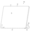
図1〜図4は、本技術の一実施形態に係る電子機器の構成を示しており、図1は正面側から見たときの斜視図、図2は背面側から見たときの斜視図、図3は設置面に対して起立した状態を示す側面図、図4は設置面に横臥した状態を示す側面図である。本実施形態の電子機器100は、例えばディスプレイ一体型の情報処理装置あるいはパーソナルコンピュータで構成されるが、これに限られず、通常のディスプレイあるいはモニタ等で構成されてもよい。
[Overall configuration of electronic equipment]
1 to 4 show a configuration of an electronic apparatus according to an embodiment of the present technology, FIG. 1 is a perspective view when viewed from the front side, and FIG. 2 is a perspective view when viewed from the back side. FIG. 3 is a side view showing a state of standing on the installation surface, and FIG. 4 is a side view showing a state lying on the installation surface. The
本実施形態の電子機器100は、本体10と、スタンド部材20と、ヒンジユニット30とを有する。
The
(本体)
本体10は、表示面Dを有する正面11と、その反対側の背面12とを有しており、全体的に略板状に構成される。表示面Dは、例えば液晶ディスプレイ、有機ELディスプレイ等で構成され、X軸方向に水平方向(横方向)、Y軸方向に垂直方向(縦方向)を有する矩形の平面で形成される。表示面Dは、タッチパネルを備えており、さらに複数のユーザによる入力操作が可能に構成されている。
(Body)
The
本体10の内部にはCPU(Central Processing Unit)/MPU(Micro Processing Unit)、メインメモリ、記憶装置、マザーボードなど、コンピュータを構成する上で必要なハードウェア部品群が内蔵されている。記憶装置としては、HDD(Hard Disk Drive)、SSD(Solid State Drive)等が挙げられる。
The
本体10の背面12は、略浅皿形状を有している。本体10の背面12は、本体10の外側に向かって突出する凸面部120を有する。凸面部120は、背面12の略中央部に形成された台座状の立体的な構造面で形成され、その先端に形成された平面的な頂部121と、頂部121の中央に向かって傾斜するテーパ状の周面122とを有する。凸面部120の内部には例えば本体10を駆動する各種駆動回路や制御回路が実装された回路基板、バッテリユニット等が配置されてもよい。
The
本体10の背面であって、凸面部120以外の領域には、図示せずとも、電源ボタン等の各種スイッチや、外部機器と電気的に接続可能に構成された複数の接続モジュール等が設けられている。外部機器としては、プリンタ、モニタ、プロジェクタ、ルータ、ハブ、パーソナルコンピュータ、カメラ、ビデオカメラ、携帯電話等の電子機器が挙げられる。接続モジュールとしては、VGA(Video Graphics Array)、LAN(Local Area Network)、USB(Universal Serial Bus)、HDMI(High-Definition Multimedia Interface)等の各種モジュールの接続ポートあるいはコネクタジャックが挙げられる。
In the area other than the
本体10は、設置面Gに接触可能な第1の支持部S1を有する。第1の支持部S1は、本体10下端の直線的な周面部に形成される。本体10は、設置面Gに第1の支持部S1を接触させ、かつ、スタンド部材20に支持されることで、設置面G上での起立状態が維持される。
The
第1の支持部S1を含む本体10の周面部は、平面上または曲面上の傾斜面で形成されている。これにより表示面Dが設置面Gに対して起立した状態から設置面Gに向けて傾けたときに、表示面Dの下端部が設置面から浮き上がることが防止される。これにより表示面Dの視認性あるいは操作性の低下を抑えることが可能となる。
The peripheral surface portion of the
(スタンド部材)
スタンド部材20は、本体10の背面12側に取り付けられる。スタンド部材20は、設置面Gに対する本体10の自立を補助するために用いられる。
(Stand member)
The
スタンド部材20は、図3に示すように設置面Gに対して本体10が所定角度傾斜した状態で起立した状態から、図4に示すように設置面Gに本体10が横臥した状態にわたって連続的に回転可能に構成される。
The
スタンド部材20は、例えば金属材料で構成され、図4に示す第2の回転位置において表示面Dと略平行であり、かつ、凸面部120の周囲に沿って屈曲した形状のアーム部を有する。これにより本体10とスタンド部材20との一体性が高まることでデザイン性が向上するとともに、電子機器100の小型化、薄型化を実現することができる。
The
本実施形態においてスタンド部材20は、全体的に帯状の部材を所定位置で略90°折り曲げて形成されており、表示面DのX軸方向に平行に延びる主アーム部21と、主アーム部21の両端に連接した一対の補助アーム部22とを有する。各々の補助アーム部22は、ヒンジユニット30を介して本体10の背面12に回動可能に取り付けられている。
In the present embodiment, the
主アーム部21は、設置面Gに接触可能な第2の支持部S2として機能する。さらに主アーム部21は、スタンド部材20を回転操作する際にユーザの手指等により操作される操作部としての機能をも有する。
The
なお、本体10が設置面Gに横臥した状態では、本体10の凸面部120は、設置面Gに接触し、第1の支持部S1に代わって本体10を支持する第3の支持部S3として機能する。
In the state where the
スタンド部材20の各アーム部21,22は、第2の回転位置において凸面部120の周面部122に対向配置される。本実施形態において各アーム部21,22は、凸面部120の周面部122に対応するテーパ状の内周縁部21s,22sを有する。これにより、第2の回転位置においてスタンド部材20を凸面部120の周面部122に近接して配置することが可能となるため、第2の回転位置においてスタンド部材20と凸面部120との一体感がより高められる。
The
(ヒンジユニット)
ヒンジユニット30は、本体10とスタンド部材20との間に接続される。本実施形態においてヒンジユニット30は、本体10の背面12側に配置されている。これによりヒンジユニット30が表示面D側から視認されにくくなり、電子機器100のデザイン性を高めることができる。
(Hinge unit)
The
ヒンジユニット30は、本体10を設置面Gに起立させる第1の回転位置(図3)と、本体10を設置面Gに横臥させる第2の回転位置(図4)との間にわたって、スタンド部材20を本体10に対して回転可能に支持する。本実施形態において、設置面Gに対する表示面Dの最大傾斜角θは75°であり、最小傾斜角は0°である。
The
本実施形態においてヒンジユニット30は、本体10の高さ方向の中心位置よりも第1の支持部S1側に配置される。これによりスタンド部材20が第2の回転位置に回転した際にスタンド部材の第2の支持部S2が本体10の周縁外側に突出することを防止できるため、電子機器100の収納時のコンパクト化を高めることができる。
In the present embodiment, the
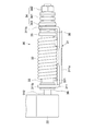
図5は、スタンド部材20とヒンジユニット30との関係を示す正面図である。図6はヒンジユニットの拡大正面図、図7はその側面図、図8は図6における[A]−[A]線方向断面図である。
FIG. 5 is a front view showing the relationship between the
本実施形態では、スタンド部材20を本体10に回転可能に支持する一対のヒンジユニット30を有する。各ヒンジユニット30は、一対の補助アーム部22の先端にそれぞれ取り付けられ、その各々は本体10の凸面部120の内部に互いに対向するように配置されている。これによりヒンジユニット30が外部から視認されなくなるため、電子機器100のデザイン性が高められる。
In this embodiment, it has a pair of
各ヒンジユニット30はそれぞれ同一の構成を有しており、それぞれヒンジ部31と、弾性部材32と、調整機構34とを有する。
Each
ヒンジ部31は、ブラケット311と、ヒンジシャフト312とを有する。ブラケット311は、本体10の背面12に複数のネジ部材(図示略)を介して固定される固定部311aと、ヒンジシャフト312を回転可能に支持する一対の支持部311bとを有する。ヒンジシャフト312は、補助アーム部22の先端に一体的に固定され、一対の支持部311bを貫通する。
The
弾性部材32は、トーションバネで構成され、スリーブ33を介してヒンジシャフト312の外周側に組み付けられている。スリーブ33は、ブラケット311の一対の支持部311b間に配置され、内部をヒンジシャフト312が貫通している。弾性部材32の一端321はブラケット311の支持部311bに係止され、他端322は、ヒンジシャフト312に固定されるリング部材35に係止されている。
The
弾性部材32は、スタンド部材20が図3に示す第1の回転位置側から図4に示す第2の回転位置側への回転操作に対して、スタンド部材20を第2の回転位置側から第1の回転位置側へ復帰させる弾性力(回転力)を発生させる。弾性部材32がトーションバネで構成されているため、スタンド部材20の回転操作量に比例した回転力を発生させることができる。
The
調整機構34は、上述した弾性部材32による回転力を適宜の大きさに設定するためのものである。調整機構34は、ブラケット311を貫通するヒンジシャフト312の先端側に設けられ、複数枚のワッシャ341と、ナット部材342と、固定リング343とを有する。
The
複数枚のワッシャ341は、ナット部材342と固定リング343の間に配置され、それぞれ金属製あるいは樹脂製のスプリングワッシャで構成される。ナット部材342は、ヒンジシャフト312の先端に螺着される。固定リング343は、ヒンジシャフト312の外周側に配置され、ヒンジシャフト312の先端側を支持するブラケット311の支持部311bに一体的に固定される。これによりナット部材342の締め付け力に応じてブラケット311に対するヒンジシャフト312の回転摩擦力が変化し、ナット部材342の締め付け力を大きくするほど、弾性部材32の弾性力に起因するスタンド部材20の回転力を制限することが可能となる。
The plurality of
なお上記以外にも、ヒンジユニット30はブラケット311とヒンジシャフト312との間にグリス等の適宜の潤滑剤が塗工され、またヒンジシャフト312の適宜の位置にワッシャ36が組み付けられている。
In addition to the above, the
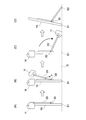
図9(A)は、本体10が設置面Gに対して所定角度(θ1)傾斜した状態で起立している様子を示す電子機器100の概略側面図である。
FIG. 9A is a schematic side view of the
この状態において、スタンド部材20は本体10に対して第1の回転位置にあり、第2の支持部S2が設置面Gに接触することで本体10の起立状態を維持する。このとき、ヒンジユニット30には、第1の支持部S1を支点として本体10の背面12側へ倒す方向の回転モーメントM1が作用し、これによりスタンド部材20には、ヒンジユニット30により、当該スタンド部材20を第1の回転位置に維持する方向への回転力Fが作用する。
In this state, the
そこで本実施形態において、調整機構34は、弾性部材32に起因する回転力Fが、第1の支持部S1を中心とする本体10の自重による回転モーメントM1とつり合う大きさに設定される。すなわち、本体10が設置面Gに対して所定角度傾斜した状態で起立しているときに、本体10の自重により設置面G側に倒れようとする方向への力を打ち消すことができ、かつ、本体10のその起立姿勢を維持できる大きさとなるように、回転力Fが調整される。
Therefore, in the present embodiment, the
ここで、上記回転モーメントM1は、角度θ1の大きさに応じて変化し、角度θ1が小さいほど回転モーメントM1が大きくなる。一方、角度θ1が小さいほど本体10に対するスタンド部材20の回転量が大きくなり、ヒンジユニット30による回転力Fは増加するため、任意の傾斜角θ1において本体10の姿勢維持が可能となる。上記回転力Fは、本体10の自重、傾斜角θ1の大きさ等に応じて設定され、本実施形態では、本体10の重量は約5kg、傾斜角θ1の最大値(θ)は約75°とされる。
Here, the rotational moment M1 changes according to the magnitude of the angle θ1, and the rotational moment M1 increases as the angle θ1 decreases. On the other hand, as the angle θ1 is smaller, the amount of rotation of the
図9(B),(C)は、本体10を設置面G側へ倒し込んでいったときの様子を示している。このときヒンジユニット30には、本体10の自重による回転モーメントに、ユーザHによる本体10への倒し込み操作力が加重された回転モーメントM2(M2>M1)が作用する。これにより上記回転力Fが相対的に低下し、ヒンジユニット30による本体10の姿勢保持力が緩和されることで、本体10の倒し込み操作によりスタンド部材20が図において反時計方向に回転する。
FIGS. 9B and 9C show a state when the
なお、例えば図9(B)に示すように任意の傾斜角θ2(θ2<θ1)でユーザHによる倒し込み操作を解除したときは、ヒンジユニット30による回転力Fにより本体10の上記傾斜角θ2での姿勢が維持される。また、図9(C)に示すように本体10が設置面Gに横臥したときは、スタンド部材20に作用する回転力Fは最大値に達するが、スタンド部材20は本体10の自重により第2の回転位置に維持される。
For example, as shown in FIG. 9B, when the tilting operation by the user H is canceled at an arbitrary inclination angle θ2 (θ2 <θ1), the inclination angle θ2 of the
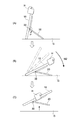
次に、本体10を設置面Gに横臥させた状態から起立させたときの典型的な動作例を図10(A)〜(C)に示す。ユーザHにより第1の支持部S1を支点として本体10を起立させると、ヒンジユニット30には本体10の自重が作用しないため、ヒンジユニット30による回転力Fがスタンド部材20に作用する。これによりスタンド部材20は、第2の支持部S2を設置面Gに接触させながら、本体10の起立に追従して第2の回転位置から第1の回転位置側へ回転する。
Next, a typical operation example when the
この際、上記回転力Fが本体10を起立させる方向へ作用するため、ユーザHにとっては、当該回転力Fによるアシスト作用を受けて、本体10の起立操作に必要な操作力が低減されることになる。また、ユーザHによる本体10の起立操作が解除されたときは、そのときの本体10の傾斜姿勢がヒンジユニット30による回転力Fにより維持される。
At this time, since the rotational force F acts in the direction in which the
以上のように本実施形態によれば、表示面Dの連続的な角度変化を可能としつつ、表示面Dの傾斜角度を安定に保持することができる。これにより表示面Dの傾斜角度が意図しない外力で容易に変化することを阻止しつつ、ユーザが容易に表示面Dの傾斜角を変更できる。 As described above, according to the present embodiment, it is possible to stably maintain the tilt angle of the display surface D while enabling a continuous angle change of the display surface D. Thus, the user can easily change the tilt angle of the display surface D while preventing the tilt angle of the display surface D from being easily changed by an unintended external force.
また本実施形態によれば、本体10の自重およびヒンジユニット30の回転力を利用できるため、表示面の傾斜角度を手動で調整する際に必要な操作力を低減することができ、本体10の重量が比較的大きい場合には取り扱い性という点で有利となる。さらに本体10に対する倒し込み操作又は起立操作に追従してスタンド部材20の角度も自動的に変化するため、スタンド部材20の角度調整が不要となり、操作性を高めることができる。
Further, according to the present embodiment, since the weight of the
一方、図11および図12は、本実施形態に係る電子機器の他の動作例を説明する概略側面図である。 On the other hand, FIG. 11 and FIG. 12 are schematic side views for explaining another operation example of the electronic apparatus according to the present embodiment.
この例において、調整機構34は、ヒンジユニット30による回転力を本体10に対するスタンド部材20の相対位置を保持できる大きさに規制する。具体的には、ナット部材342をさらに締め付けることにより、スタンド部材20に作用する回転力が上述の例よりも小さくなるようにヒンジユニット30が構成される。
In this example, the
この場合、スタンド部材20は、ヒンジユニット30による回転力によって本体10に対して回転することはない。このため、本体10を設置面G上に設置する場合には、図11(A)〜(D)に示すように第1の支持部S1を介して本体10を設置面Gに設置した状態でスタンド部材20を第2の回転位置から所望とする角度まで回転させる。
In this case, the
本例においては、スタンド部材20の回転操作時にヒンジユニット30による回転力F’がスタンド部材20に作用するため、スタンド部材20の回転操作力が低減され、スタンド部材20の操作性を向上させることができる。
In this example, since the rotational force F ′ generated by the
本例において、調整機構34は、スタンド部材20の第2の回転位置から第1の回転位置側への所定角度範囲において上記回転力F’に対する規制を解除するように構成されてもよい。この場合、図13に示すように、本体10の背面12とスタンド部材20との間に所定の隙間Sが形成されるため、当該隙間Sにユーザの手指が入り易くなり、これによりスタンド部材20の操作性を高めることができる。
In this example, the
上記操作は、本体10の傾斜角度を大きくする場合にも同様に適用される。これに対して、本体10の傾斜角度を小さくする場合には、上述の例と同様に、本体10を設置面G側に倒し込めばよい(図12(A),(B))。この場合も、スタンド部材20を所望の角度位置に回転させることができるとともに、ヒンジユニット30による回転力F’によって所望の回転位置に維持することができる。
The above operation is similarly applied when increasing the tilt angle of the
さらに本例においては、ヒンジユニット30による回転力F’が本体10に対するスタンド部材20の相対位置を保持できる大きさに規制されているため、図12(C)に示すように表示面Dの傾斜角度を維持した状態で、本体10を他の設置面上に移し替えることができ、あらためて表示面Dの傾斜角度を設定する必要がなくなる。
Furthermore, in this example, since the rotational force F ′ by the
以上、本技術の実施形態について説明したが、本技術は上述の実施形態にのみ限定されるものではなく、本技術の要旨を逸脱しない範囲内において種々変更を加え得ることは勿論である。 As mentioned above, although embodiment of this technique was described, this technique is not limited only to the above-mentioned embodiment, Of course, in the range which does not deviate from the summary of this technique, various changes can be added.
例えば以上の実施形態では、電子機器100としてディスプレイ一体型の情報処理装置を例に挙げて説明したが、これに限られず、モニタ単体やテレビジョンセット等のような表示面を有する他の電子機器にも本技術は適用可能である。
For example, in the above embodiment, the display integrated information processing apparatus has been described as an example of the
また以上の実施形態では、本体10として背面12に凸面部120を有する例を説明したが、仕様に応じて凸面部120は省略されてもよい。また、上記背面12の形状は曲面形状である場合に限られず、平面形状であってもよい。
Moreover, although the above embodiment demonstrated the example which has the
さらに以上の実施形態では、スタンド部材20を単独の部材で構成したが、複数の部材で構成されてもよい。またスタンド部材20の形状も上述した屈曲形状のものに限られず、T字状、L字状のような他の幾何学的形状で構成されてもよい。
Furthermore, in the above embodiment, although the
さらに以上の実施形態では、スタンド部材20の各補助アーム部22に対してそれぞれ同一構成のヒンジユニット30を設けたが、これに代えて、いずれか一方のアーム部に本技術に係るヒンジユニットを適用し、他のアーム部に対しては既存のヒンジ部品を適用してもよい。
Further, in the above embodiment, the
なお、本技術は以下のような構成も採ることができる。
(1) 表示面を有する第1の面と、前記第1の面とは反対側の第2の面と、前記第1の面と前記第2の面との間に設けられ設置面に接触可能な第1の支持部とを有する本体と、
前記本体に取り付けられ、前記設置面に接触可能な第2の支持部を有するスタンド部材と、
前記本体を前記設置面に起立させる第1の回転位置と前記本体を前記設置面に横臥させる第2の回転位置との間にわたって前記スタンド部材を前記本体に対して回転可能に支持するヒンジ部と、前記ヒンジ部に設けられ前記第2の回転位置側から前記第1の回転位置側へ向かう回転力を前記スタンド部材に付与する弾性部材とを有するヒンジユニットと
を具備する電子機器。
(2)前記(1)に記載の電子機器であって、
前記ヒンジユニットは、前記回転力を設定することが可能な調整機構をさらに有し、
前記調整機構は、前記回転力が、前記第1の支持部を中心とする前記本体の自重による回転モーメントとつり合う大きさに設定される
電子機器。
(3)前記(2)に記載の電子機器であって、
前記調整機構は、前記回転力を前記本体に対する前記スタンド部材の相対位置を保持できる大きさに規制する
電子機器。
(4)前記(3)に記載の電子機器であって、
前記調整機構は、前記第2の回転位置から前記第1の回転位置側への所定角度範囲において前記回転力に対する規制を解除する
電子機器。
(5)前記(1)から(4)のいずれか1つに記載の電子機器であって、
前記弾性部材は、トーションバネを含む
電子機器。
(6)前記(1)から(5)のいずれか1つに記載の電子機器であって、
前記ヒンジユニットは、前記第2の面に配置される
電子機器。
(7)前記(1)から(6)のいずれか1つに記載の電子機器であって、
前記ヒンジユニットは、前記本体の高さ方向の中心位置よりも前記第1の支持部側に配置される
電子機器。
(8)前記(1)から(7)のいずれか1つに記載の電子機器であって、
前記第2の面は、前記本体の外側に向かって突出する凸面部を有し、
前記凸面部は、前記スタンド部材が前記第2の回転位置に回転したときに前記設置面に接触可能な第3の支持部を有する
電子機器。
(9)前記(8)に記載の電子機器であって、
前記スタンド部材は、前記第2の回転位置において前記凸面部の周囲に沿って屈曲した形状のアーム部を有する
電子機器。
(10)前記(9)に記載の電子機器であって、
前記凸面部は、前記凸面部の先端中央部に向かって傾斜するテーパ状の周面を有し、
前記アーム部は、前記周面に対向し前記周面に対応するテーパ状の内周縁部を有する
電子機器。
(11)前記(1)から(10)のいずれか1つに記載の電子機器であって、
前記第1の支持部は、前記本体の一周面部に設けられ、
前記周面部は、平面状または曲面状の傾斜面で形成される
電子機器。
In addition, this technique can also take the following structures.
(1) A first surface having a display surface, a second surface opposite to the first surface, and a contact surface provided between the first surface and the second surface A body having a possible first support;
A stand member attached to the main body and having a second support part capable of contacting the installation surface;
A hinge portion that rotatably supports the stand member relative to the main body between a first rotational position where the main body stands on the installation surface and a second rotational position where the main body lies on the installation surface; An electronic device comprising: a hinge unit that includes an elastic member that is provided in the hinge portion and applies a rotational force from the second rotational position side toward the first rotational position side to the stand member.
(2) The electronic device according to (1),
The hinge unit further includes an adjustment mechanism capable of setting the rotational force,
The adjustment mechanism is an electronic apparatus in which the rotational force is set to a magnitude that balances a rotational moment due to the weight of the main body with the first support portion as a center.
(3) The electronic device according to (2),
The adjustment mechanism restricts the rotational force to a size capable of maintaining a relative position of the stand member with respect to the main body.
(4) The electronic device according to (3),
The electronic device is configured to release the restriction on the rotational force in a predetermined angle range from the second rotational position to the first rotational position.
(5) The electronic device according to any one of (1) to (4),
The elastic member is an electronic device including a torsion spring.
(6) The electronic device according to any one of (1) to (5),
The hinge unit is an electronic device disposed on the second surface.
(7) The electronic device according to any one of (1) to (6),
The said hinge unit is an electronic device arrange | positioned rather than the center position of the height direction of the said main body at the said 1st support part side.
(8) The electronic device according to any one of (1) to (7),
The second surface has a convex surface portion protruding toward the outside of the main body,
The convex portion includes an electronic device having a third support portion that can come into contact with the installation surface when the stand member rotates to the second rotation position.
(9) The electronic device according to (8),
The electronic apparatus according to
(10) The electronic device according to (9),
The convex surface portion has a tapered peripheral surface inclined toward the center of the tip of the convex surface portion,
The said arm part is an electronic device which has a taper-shaped inner peripheral part facing the said surrounding surface and corresponding to the said surrounding surface.
(11) The electronic device according to any one of (1) to (10),
The first support portion is provided on a circumferential surface portion of the main body,
The peripheral surface portion is an electronic device formed of a flat or curved inclined surface.
10…本体
20…スタンド部材
30…ヒンジユニット
31…ヒンジ部
32…弾性部材
34…調整機構
100…電子機器
120…凸面部
D…表示面
F,F’…回転力
G…設置面
S1…第1の支持部
S2…第2の支持部
S3…第3の支持部
DESCRIPTION OF
Claims (11)
前記本体に取り付けられ、前記設置面に接触可能な第2の支持部を有するスタンド部材と、
前記本体を前記設置面に起立させる第1の回転位置と前記本体を前記設置面に横臥させる第2の回転位置との間にわたって前記スタンド部材を前記本体に対して回転可能に支持するヒンジ部と、前記ヒンジ部に設けられ前記第2の回転位置側から前記第1の回転位置側へ向かう回転力を前記スタンド部材に付与する弾性部材とを有するヒンジユニットと
を具備する電子機器。 A first surface having a display surface; a second surface opposite to the first surface; and a first surface provided between the first surface and the second surface and capable of contacting the installation surface. A main body having one support portion;
A stand member attached to the main body and having a second support part capable of contacting the installation surface;
A hinge portion that rotatably supports the stand member relative to the main body between a first rotational position where the main body stands on the installation surface and a second rotational position where the main body lies on the installation surface; An electronic device comprising: a hinge unit that includes an elastic member that is provided in the hinge portion and applies a rotational force from the second rotational position side toward the first rotational position side to the stand member.
前記ヒンジユニットは、前記回転力を設定することが可能な調整機構をさらに有し、
前記調整機構は、前記回転力が、前記第1の支持部を中心とする前記本体の自重による回転モーメントとつり合う大きさに設定される
電子機器。 The electronic device according to claim 1,
The hinge unit further includes an adjustment mechanism capable of setting the rotational force,
The adjustment mechanism is an electronic apparatus in which the rotational force is set to a magnitude that balances a rotational moment due to the weight of the main body with the first support portion as a center.
前記調整機構は、前記回転力を前記本体に対する前記スタンド部材の相対位置を保持できる大きさに規制する
電子機器。 The electronic device according to claim 2,
The adjustment mechanism restricts the rotational force to a size capable of maintaining a relative position of the stand member with respect to the main body.
前記調整機構は、前記第2の回転位置から前記第1の回転位置側への所定角度範囲において前記回転力に対する規制を解除する
電子機器。 The electronic device according to claim 3,
The electronic device is configured to release the restriction on the rotational force in a predetermined angle range from the second rotational position to the first rotational position.
前記弾性部材は、トーションバネを含む
電子機器。 The electronic device according to claim 1,
The elastic member is an electronic device including a torsion spring.
前記ヒンジユニットは、前記第2の面に配置される
電子機器。 The electronic device according to claim 1,
The hinge unit is an electronic device disposed on the second surface.
前記ヒンジユニットは、前記本体の高さ方向の中心位置よりも前記第1の支持部側に配置される
電子機器。 The electronic device according to claim 1,
The said hinge unit is an electronic device arrange | positioned rather than the center position of the height direction of the said main body at the said 1st support part side.
前記第2の面は、前記本体の外側に向かって突出する凸面部を有し、
前記凸面部は、前記スタンド部材が前記第2の回転位置に回転したときに前記設置面に接触可能な第3の支持部を有する
電子機器。 The electronic device according to claim 1,
The second surface has a convex surface portion protruding toward the outside of the main body,
The convex portion includes an electronic device having a third support portion that can come into contact with the installation surface when the stand member rotates to the second rotation position.
前記スタンド部材は、前記第2の回転位置において前記凸面部の周囲に沿って屈曲した形状のアーム部を有する
電子機器。 The electronic device according to claim 8,
The electronic apparatus according to claim 1, wherein the stand member has an arm portion that is bent along the periphery of the convex surface portion at the second rotational position.
前記凸面部は、前記凸面部の先端中央部に向かって傾斜するテーパ状の周面を有し、
前記アーム部は、前記周面に対向し前記周面に対応するテーパ状の内周縁部を有する
電子機器。 The electronic device according to claim 9,
The convex surface portion has a tapered peripheral surface inclined toward the center of the tip of the convex surface portion,
The said arm part is an electronic device which has a taper-shaped inner peripheral part facing the said surrounding surface and corresponding to the said surrounding surface.
前記第1の支持部は、前記本体の一周面部に設けられ、
前記周面部は、平面状または曲面状の傾斜面で形成される
電子機器。 The electronic device according to claim 1,
The first support portion is provided on a circumferential surface portion of the main body,
The peripheral surface portion is an electronic device formed of a flat or curved inclined surface.
Priority Applications (3)
| Application Number | Priority Date | Filing Date | Title |
|---|---|---|---|
| JP2012188809A JP2014048328A (en) | 2012-08-29 | 2012-08-29 | Electronic apparatus |
| CN201310368344.3A CN103672322B (en) | 2012-08-29 | 2013-08-22 | Electronic equipment |
| US13/973,293 US20140063772A1 (en) | 2012-08-29 | 2013-08-22 | Electronic apparatus |
Applications Claiming Priority (1)
| Application Number | Priority Date | Filing Date | Title |
|---|---|---|---|
| JP2012188809A JP2014048328A (en) | 2012-08-29 | 2012-08-29 | Electronic apparatus |
Publications (2)
| Publication Number | Publication Date |
|---|---|
| JP2014048328A true JP2014048328A (en) | 2014-03-17 |
| JP2014048328A5 JP2014048328A5 (en) | 2015-04-16 |
Family
ID=50187328
Family Applications (1)
| Application Number | Title | Priority Date | Filing Date |
|---|---|---|---|
| JP2012188809A Pending JP2014048328A (en) | 2012-08-29 | 2012-08-29 | Electronic apparatus |
Country Status (3)
| Country | Link |
|---|---|
| US (1) | US20140063772A1 (en) |
| JP (1) | JP2014048328A (en) |
| CN (1) | CN103672322B (en) |
Families Citing this family (9)
| Publication number | Priority date | Publication date | Assignee | Title |
|---|---|---|---|---|
| TWI524024B (en) * | 2014-03-05 | 2016-03-01 | 佳世達科技股份有限公司 | Display device |
| CN103851070A (en) * | 2014-04-02 | 2014-06-11 | 昆山市张浦镇佳聚辉电子厂 | Electronic product rotating shaft support frame |
| CN110636155B (en) * | 2019-09-17 | 2021-03-19 | Oppo广东移动通信有限公司 | Shell assembly and electronic device |
| US10835106B1 (en) | 2020-02-21 | 2020-11-17 | Ambu A/S | Portable monitor |
| US10980397B1 (en) | 2020-02-21 | 2021-04-20 | Ambu A/S | Video processing device |
| US11109741B1 (en) | 2020-02-21 | 2021-09-07 | Ambu A/S | Video processing apparatus |
| US11166622B2 (en) | 2020-02-21 | 2021-11-09 | Ambu A/S | Video processing apparatus |
| CN112032486A (en) * | 2020-08-24 | 2020-12-04 | 义乌工商职业技术学院 | LED show window for teaching show |
| CN112073805B (en) * | 2020-08-26 | 2022-12-09 | 海信视像科技股份有限公司 | Display mirror |
Citations (6)
| Publication number | Priority date | Publication date | Assignee | Title |
|---|---|---|---|---|
| JPH04273283A (en) * | 1991-02-28 | 1992-09-29 | Canon Inc | Electronic equipment |
| JPH07261673A (en) * | 1994-03-24 | 1995-10-13 | Sharp Corp | Display stand |
| JPH11259171A (en) * | 1998-03-06 | 1999-09-24 | Toshiba Corp | Information processor |
| JP2001034181A (en) * | 1999-07-22 | 2001-02-09 | Totoku Electric Co Ltd | Panel type display device |
| JP2007281345A (en) * | 2006-04-11 | 2007-10-25 | Sony Corp | Stand rotation mechanism, and electronic apparatus |
| JP2008257562A (en) * | 2007-04-06 | 2008-10-23 | Sharp Corp | Support stand |
Family Cites Families (27)
| Publication number | Priority date | Publication date | Assignee | Title |
|---|---|---|---|---|
| US2388567A (en) * | 1943-01-28 | 1945-11-06 | Philco Radio & Television Corp | Portable radio receiver |
| US5235495A (en) * | 1992-09-21 | 1993-08-10 | Telepad Corporation | Pen-based computer with handle/prop having ratchet locking mechanism |
| US5375076A (en) * | 1993-09-10 | 1994-12-20 | Compaq Computer Corporation | Combined notepad and notebook computer |
| US5812368A (en) * | 1997-06-04 | 1998-09-22 | Kuo Feng Corporation | Monitor viewing angle adjusting assembly having monitor mounted on two supporting arm assemblies via turning limit assemblies |
| KR100558949B1 (en) * | 1999-05-03 | 2006-03-10 | 삼성전자주식회사 | Structure For Fixing Handle Of L.C.D Monitor |
| KR100367586B1 (en) * | 1999-10-08 | 2003-01-10 | 엘지전자 주식회사 | Flat type monitor |
| KR100364732B1 (en) * | 2000-07-08 | 2002-12-16 | 엘지전자 주식회사 | Hinge assembly in LCD monitor |
| JP4094937B2 (en) * | 2001-11-19 | 2008-06-04 | 三星電子株式会社 | Monitor device |
| KR100463524B1 (en) * | 2002-05-29 | 2004-12-29 | 엘지전자 주식회사 | Hinge assembly for video display appliance |
| US6796541B2 (en) * | 2002-08-29 | 2004-09-28 | Shin Zu Shing Co., Ltd. | Support for an LCD monitor |
| KR100482007B1 (en) * | 2002-09-28 | 2005-04-13 | 삼성전자주식회사 | Monitor |
| US6899311B1 (en) * | 2003-01-22 | 2005-05-31 | Apple Computer, Inc. | Easel display arrangement |
| TWI255686B (en) * | 2004-06-03 | 2006-05-21 | Asustek Comp Inc | Bracket structure and electronic apparatus |
| US7565719B2 (en) * | 2004-06-18 | 2009-07-28 | Sinher Technology Inc. | Hinge for anchoring and folding on a small pintle |
| US20060050471A1 (en) * | 2004-09-03 | 2006-03-09 | Yin-Hung Chen | Monitor frame structure |
| US20060049327A1 (en) * | 2004-09-03 | 2006-03-09 | Yin-Hung Chen | Monitor supporting and rotating structure |
| TWM333751U (en) * | 2007-09-07 | 2008-06-01 | Jarllytec Co Ltd | Supporting-type pivot structure |
| TWI335969B (en) * | 2007-11-21 | 2011-01-11 | Compal Electronics Inc | Adjustable supporting mechanism and electronic apparatus |
| TWI358986B (en) * | 2008-06-20 | 2012-02-21 | Qisda Corp | Electronic device |
| CN101754609B (en) * | 2008-12-08 | 2012-08-22 | 深圳富泰宏精密工业有限公司 | Portable electronic device |
| CN101770258B (en) * | 2008-12-31 | 2013-08-07 | 鸿富锦精密工业(深圳)有限公司 | Portable electronic device |
| TWI434643B (en) * | 2009-11-03 | 2014-04-11 | Asustek Comp Inc | Electronic device with supporting stand |
| TWI428015B (en) * | 2010-05-14 | 2014-02-21 | Qisda Corp | Display device |
| KR101797241B1 (en) * | 2011-03-02 | 2017-11-13 | 삼성전자주식회사 | Slim-type cradle for mobile phone |
| CN102736671A (en) * | 2011-04-02 | 2012-10-17 | 鸿富锦精密工业(深圳)有限公司 | Electronic device |
| TWI470404B (en) * | 2011-04-07 | 2015-01-21 | Wistron Corp | Adjusting device of adjusting view angle of a panel module and computer system having the same |
| TWI457065B (en) * | 2011-10-28 | 2014-10-11 | Inventec Corp | Portable electronic device |
-
2012
- 2012-08-29 JP JP2012188809A patent/JP2014048328A/en active Pending
-
2013
- 2013-08-22 CN CN201310368344.3A patent/CN103672322B/en not_active Expired - Fee Related
- 2013-08-22 US US13/973,293 patent/US20140063772A1/en not_active Abandoned
Patent Citations (6)
| Publication number | Priority date | Publication date | Assignee | Title |
|---|---|---|---|---|
| JPH04273283A (en) * | 1991-02-28 | 1992-09-29 | Canon Inc | Electronic equipment |
| JPH07261673A (en) * | 1994-03-24 | 1995-10-13 | Sharp Corp | Display stand |
| JPH11259171A (en) * | 1998-03-06 | 1999-09-24 | Toshiba Corp | Information processor |
| JP2001034181A (en) * | 1999-07-22 | 2001-02-09 | Totoku Electric Co Ltd | Panel type display device |
| JP2007281345A (en) * | 2006-04-11 | 2007-10-25 | Sony Corp | Stand rotation mechanism, and electronic apparatus |
| JP2008257562A (en) * | 2007-04-06 | 2008-10-23 | Sharp Corp | Support stand |
Also Published As
| Publication number | Publication date |
|---|---|
| CN103672322A (en) | 2014-03-26 |
| CN103672322B (en) | 2017-11-03 |
| US20140063772A1 (en) | 2014-03-06 |
Similar Documents
| Publication | Publication Date | Title |
|---|---|---|
| JP2014048328A (en) | Electronic apparatus | |
| US11397448B2 (en) | Notebook computer with a functional body | |
| US8755181B2 (en) | Electronic device | |
| KR101672808B1 (en) | Support assembly and computer device having the same | |
| US8979040B2 (en) | Supporting device | |
| JP6077060B2 (en) | Stand mechanism and electronic device | |
| US9395761B2 (en) | Information processing apparatus | |
| US20110279962A1 (en) | Support Frame and Electronic Apparatus | |
| US20120228346A1 (en) | Handheld accessory for tablet computers | |
| US9271409B2 (en) | Terminal device | |
| JP2006195217A (en) | Stand for thin type display device | |
| US9179567B2 (en) | Electronic device | |
| TWI497264B (en) | Electronic device | |
| JP4980317B2 (en) | Information processing device | |
| EP3297261B1 (en) | Hinge, stand device, and electronic apparatus | |
| US20140328012A1 (en) | Foot support assembly for cantilevered touch screen | |
| TWI457748B (en) | External inputting device and related detachable computer system | |
| US20140192461A1 (en) | Hinge structure and electronic device using the same | |
| US8893353B2 (en) | Opening/closing apparatus and hinge device thereof | |
| CN102979812A (en) | Pan-tilt universal positioning mechanism and light control console employing same | |
| CN108612988B (en) | Electronic device and support frame thereof | |
| CN202991830U (en) | Cradle head universal locating mechanism and light console with same | |
| TWI831230B (en) | Electronic device | |
| JPH0756653A (en) | Information processor | |
| TWI585575B (en) | Portable electronic device |
Legal Events
| Date | Code | Title | Description |
|---|---|---|---|
| A521 | Request for written amendment filed |
Free format text: JAPANESE INTERMEDIATE CODE: A523 Effective date: 20150226 |
|
| A621 | Written request for application examination |
Free format text: JAPANESE INTERMEDIATE CODE: A621 Effective date: 20150226 |
|
| A131 | Notification of reasons for refusal |
Free format text: JAPANESE INTERMEDIATE CODE: A131 Effective date: 20151201 |
|
| A521 | Request for written amendment filed |
Free format text: JAPANESE INTERMEDIATE CODE: A523 Effective date: 20160201 |
|
| A131 | Notification of reasons for refusal |
Free format text: JAPANESE INTERMEDIATE CODE: A131 Effective date: 20160809 |
|
| A521 | Request for written amendment filed |
Free format text: JAPANESE INTERMEDIATE CODE: A523 Effective date: 20161011 |
|
| A02 | Decision of refusal |
Free format text: JAPANESE INTERMEDIATE CODE: A02 Effective date: 20170328 |