JP2014007687A - Antenna and wireless communication device including the same - Google Patents
Antenna and wireless communication device including the same Download PDFInfo
- Publication number
- JP2014007687A JP2014007687A JP2012143745A JP2012143745A JP2014007687A JP 2014007687 A JP2014007687 A JP 2014007687A JP 2012143745 A JP2012143745 A JP 2012143745A JP 2012143745 A JP2012143745 A JP 2012143745A JP 2014007687 A JP2014007687 A JP 2014007687A
- Authority
- JP
- Japan
- Prior art keywords
- antenna
- phase
- amplitude
- radiation
- elements
- Prior art date
- Legal status (The legal status is an assumption and is not a legal conclusion. Google has not performed a legal analysis and makes no representation as to the accuracy of the status listed.)
- Granted
Links
Images


Landscapes
- Variable-Direction Aerials And Aerial Arrays (AREA)
Abstract
Description
本発明は、アンテナおよびこれを備えた無線通信装置に関し、特に、基地局アンテナとして使用されるアンテナおよびこれを用いた無線通信装置に関する。 The present invention relates to an antenna and a radio communication apparatus including the antenna, and more particularly to an antenna used as a base station antenna and a radio communication apparatus using the antenna.
移動体通信用に用いられる基地局アンテナは、通常は高所に設置される。アンテナから放射される電波によって、基地局と地上の固定通信端末あるいは移動体通信端末との間でデータの送受信が行われる。基地局アンテナの一つに、垂直方向に複数のアンテナ素子を配置し、アンテナ素子にそれぞれ所定の振幅・位相を給電する給電回路を備えるものがある。 A base station antenna used for mobile communication is usually installed at a high place. Data is transmitted and received between the base station and the ground fixed communication terminal or mobile communication terminal by radio waves radiated from the antenna. One of the base station antennas includes a plurality of antenna elements arranged in a vertical direction and provided with a power feeding circuit that feeds each antenna element with a predetermined amplitude and phase.
例えば、特許文献1には、複数のアンテナ素子に、奇関数で表される第1の位相分布と偶関数で表される第2の位相分布とが合成された位相を付加することにより、天空方向の放射が抑圧され、地上方向にコセカント2乗カーブとなる、ヌルフィルビームを実現するアンテナが開示されている。 For example, Patent Document 1 discloses that a plurality of antenna elements are added with a phase obtained by combining a first phase distribution represented by an odd function and a second phase distribution represented by an even function, thereby An antenna that realizes a null-fill beam is disclosed in which direction radiation is suppressed and a cosecant square curve is formed in the ground direction.
天空方向の放射が抑圧されることにより、基地局アンテナ間や基地局アンテナと衛星通信間との干渉が低減される。また、コセカント2乗カーブの放射特性を有することにより、基地局と通信を行う移動体端末は、基地局アンテナからの距離によらず、地上における電界強度が略一定となる。 By suppressing the radiation in the sky direction, interference between the base station antennas and between the base station antenna and the satellite communication is reduced. In addition, by having the radiation characteristic of the cosecant square curve, the mobile terminal that communicates with the base station has a substantially constant electric field intensity on the ground regardless of the distance from the base station antenna.
ここで、良好な通信品質を維持するために、アンテナから放射されるビームの放射ゲインは所定レベル以上であることが望ましい。また、地上側の所望方向に電波が放射されるように、メインビームの放射角度を、アンテナ水平面から所定の角度に設定できることが望ましい。 Here, in order to maintain good communication quality, it is desirable that the radiation gain of the beam radiated from the antenna is not less than a predetermined level. In addition, it is desirable that the radiation angle of the main beam can be set to a predetermined angle from the antenna horizontal plane so that radio waves are radiated in a desired direction on the ground side.
なお、メインビームの放射角度は、アンテナからの放射パターンが一定の角度となるように電気的に設定される電気チルトと、アンテナを傾斜させて設置することによって設定される機械チルトと、によって設定することができる。 Note that the radiation angle of the main beam is set by an electrical tilt that is electrically set so that the radiation pattern from the antenna becomes a constant angle, and a mechanical tilt that is set by tilting the antenna. can do.
本発明の目的は、上記の課題に鑑みなされたものであり、天空方向の放射が抑圧され、地上方向にコセカント2乗カーブとなる放射パターンを有すると共に、高い放射ゲインを維持しつつ電気チルトを有する、アンテナよびこれを備えた無線通信装置を提供することにある。 The object of the present invention has been made in view of the above problems, and has an emission pattern in which the radiation in the sky direction is suppressed, has a cosecant square curve in the ground direction, and an electric tilt is maintained while maintaining a high radiation gain. It is an object of the present invention to provide an antenna and a wireless communication apparatus including the antenna.
上記目的を達成するために本発明に係るアンテナは、アレイ状に配置された複数のアンテナ素子と、アンテナ素子に、アレイの両端側に行くに従って低下する振幅、および、一端側に行くに従って進み量が大きくなると共に他端側に行くに従って遅れ量が大きくなる位相を給電する給電手段と、を備える。 In order to achieve the above object, an antenna according to the present invention includes a plurality of antenna elements arranged in an array, the amplitude of the antenna elements decreasing as it goes to both ends of the array, and the advance amount as it goes to one end. And a power feeding means for feeding a phase in which the delay amount increases as going to the other end side.
上記目的を達成するために本発明に係る無線通信装置は、上記のアンテナを備えた無線通信装置である。 In order to achieve the above object, a wireless communication apparatus according to the present invention is a wireless communication apparatus provided with the antenna described above.
本発明に係るアンテナよびこれを備えた無線通信装置は、天空方向の放射が抑圧され、地上方向にコセカント2乗カーブとなる放射パターンを有すると共に、高い放射ゲインを維持しつつ電気チルトを有する。 The antenna and the wireless communication apparatus including the antenna according to the present invention have a radiation pattern that suppresses radiation in the sky direction, forms a cosecant square curve in the ground direction, and has an electric tilt while maintaining a high radiation gain.
(第1の実施形態)
本発明の第1の実施形態に係るアンテナについて説明する。本実施形態に係るアンテナのブロック構成図を図1(a)に示す。図1(a)において、本実施形態に係るアンテナ10は、複数のアンテナ素子21、22、…、2n(nは5以上の整数)および給電手段30を備える。
(First embodiment)
An antenna according to a first embodiment of the present invention will be described. FIG. 1A shows a block configuration diagram of an antenna according to the present embodiment. 1A, the
本実施形態において、アンテナ10は基地局アンテナとして用いられ、アンテナ10は、アンテナ素子21が地上側に、アンテナ素子2nが天頂側に来るように縦長に設置される。
In the present embodiment, the
なお、アンテナ10を移動体通信用に用いられる基地局アンテナとして用いる場合、垂直面で6度程度、水平面で60〜180度のビーム幅のビームパターンに成形することが望ましい。所望のゲインを維持した状態で、垂直面で6度程度のビーム幅を成形するため、アンテナ素子の数は12〜14素子程度とすると良い。また、水平面で60〜180度のビーム幅を得るため、アンテナ素子の背面に金属板からなる反射板を配置すると良い。さらに、屋外環境に耐えるために、アンテナ10をFRP(Fiber Reinforced Plastics:繊維強化プラスチック)、PPE(poly phenylene ether:ポリフェニレンエーテル)、ABS等の樹脂で作成したレドームで覆うこともできる。
When the
図1(a)の説明に戻る。複数のアンテナ素子21、22、…、2nはアレイ状に配置され、それぞれ給電手段30から給電された振幅・位相に応じた電磁波を空間に放射すると共に空間から電磁波を受信する。本実施形態において、アンテナ素子21、22、…、2nは、アンテナ素子2kを中心として、等間隔で一列に配置されている。
Returning to the description of FIG. The plurality of
給電手段30は、アレイ状に配置されたアンテナ素子21、22、…、2nへ、アレイの両端側に行くに従って低下する振幅、および、一端側に行くに従って進み量が大きくなると共に他端側に行くに従って遅れ量が大きくなる位相を給電する。
The power feeding means 30 has an amplitude that decreases as it goes to both ends of the array, and an advance amount that increases toward the one end, and increases toward the other end, toward the
給電手段30が7素子のアンテナ素子21、22、…、27に給電する場合について説明する。この場合の給電分布の一例を図1(b)に示す。図1(b)に示すように、本実施形態に係る給電手段30は、中心に配置されたアンテナ素子24に最も大きな振幅の電力を供給し、アンテナ素子2kから線対象となるように、両端に配置されたアンテナ素子21およびアンテナ素子27に向かって給電する電力の振幅を小さくする。
A case where the power feeding means 30 feeds power to the seven
さらに、図1(b)に示すように、給電手段30は、中心に配置されたアンテナ素子24から他端側のアンテナ素子21に向かって変化量が大きくなるように位相を遅らせ、中心に配置されたアンテナ素子24から一端側のアンテナ素子27に向かって変化量が大きくなるように位相を進ませる。
Further, as shown in FIG. 1B, the
アレイ状に配置されたアンテナ素子21、22、…、27に、図1(b)に示した振幅・位相を給電することにより、アンテナ10の放射特性が、天空方向の放射が抑圧され、地上方向にコセカント2乗カーブとなる放射パターンを有すると共に、高い放射ゲインを維持しつつ電気チルトを有するようになる。
By feeding the
ここで、アンテナ素子24からアンテナ素子21、27に行くに従って、振幅の低下量を大きくする場合、さらに、天空方向の放射を抑圧することができる。一方、アンテナ素子24からアンテナ素子21、27までの振幅の低下量を一定にする場合、放射特性に落ち込み(ヌル)を低減することができる。
Here, when the amount of decrease in amplitude is increased from the
以上のように、本実施形態に係るアンテナ10は、アレイ状に配置された複数のアンテナ素子に、アレイの両端側に行くに従って低下する振幅、および、一端側に行くに従って進み量が大きくなると共に他端側に行くに従って遅れ量が大きくなる位相を給電する。この場合、アンテナ10の放射特性が、天空方向の放射が抑圧され、地上方向にコセカント2乗カーブとなる放射パターンを有すると共に、高い放射ゲインを維持しつつ電気チルトを有するようになる。
As described above, the
本実施形態に係るアンテナ10を基地局アンテナに適用する場合、天空方向の放射が抑圧されることにより、基地局アンテナ間や基地局アンテナと衛星通信装置間等の干渉を低減することができる。また、地上方向にコセカント2乗カーブとなる放射パターンを有することにより、基地局と通信を行う移動体端末が、基地局アンテナからの距離によらない略一定の電界強度の放射特性を得ることができる。また、ヌルが抑制されることにより、通信品質が低いエリアを縮小することができる。
When the
さらに、アンテナ10を基地局アンテナに適用する場合、高い放射ゲインを維持しつつ電気チルトを有することにより、基地局の足下付近の電界強度を所望の強度に維持できる。
Further, when the
(第2の実施形態)
第2の実施形態について説明する。本実施形態に係るアンテナをアンテナ取り付け用ポールに取り付けた時の斜視図を図2に示す。図2において、本実施形態に係るアンテナ100は、長手方向が天地方向となるようにして、2つの取付金具700を介してアンテナ取り付け用ポール800に固定される。
(Second Embodiment)
A second embodiment will be described. FIG. 2 shows a perspective view when the antenna according to this embodiment is attached to the antenna attachment pole. In FIG. 2, the
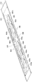
本実施形態に係るアンテナ100の透過斜視図を図3(a)に、図3(a)のアンテナ100をX―X線で切断した時の断面図を図3(b)に示す。図3(a)、(b)において、本実施形態に係るアンテナ100は、筐体200、13個の放射素子300a−300m、13個のセンターポール400a−400m、および、プリント基板500を備える。
FIG. 3A is a transparent perspective view of the
筐体200は、本体210およびカバー220を備える。本体210は、金属板を折り曲げることによって形成された長尺の箱体である。本体210は内部に、低背で上方が解放された矩形型の空間を備える。この空間の内部に、放射素子300a−300m、センターポール400a−400mおよびプリント基板500が配置される。
The
カバー220は金属製の板体であり、本体210の上方に配置されることにより、放射素子300a−300m、センターポール400a−400mおよびプリント基板500が配置された空間を覆う。なお、アンテナ100の保護のために、筐体200をFRP(Fiber Reinforced Plastics:繊維強化プラスチック)やPPC(ポリプロピレンカーボネート)等の樹脂ケース内に配置することもできる。
The
放射素子300a−300mはそれぞれ、センターポール400a−400mを介して、プリント基板500に形成された放射素子510a−510mと接続されている。本実施形態において、放射素子300a−300mおよび放射素子510a−510mは、センターポール400a−400mを介して接続されることで、パッチアンテナ600a−600mを構成している。
The radiating
センターポール400a−400mはそれぞれ、放射素子300a−300mおよびプリント基板500上に形成された放射素子510a−510mを接続する。放射素子300a−300mおよび放射素子510a−510mをセンターポール400a−400mで接続することにより、パッチアンテナ600a−600mの広帯域化が図られる。
プリント基板500は、誘電体等によって形成され、筐体200の本体210の内部に配置される。プリント基板500を本体210に配置した時の斜視図を図4に示す。図4に示すように、本実施形態に係るプリント基板500は本体210に固定され、上面に13個の放射素子510a−510m、給電ポイント520、530、および、給電回路540、550が形成されている。
The printed
放射素子510a−510mは、プリント基板500の上面に所定の間隔で1列に形成されている。上述のように、放射素子510a−510mはそれぞれ、センターポール400a−400mを介して放射素子300a−300mと接続されることにより、パッチアンテナ600a−600mを構成する。
The radiating elements 510a to 510m are formed in one row on the upper surface of the printed
給電ポイント520、530は、給電回路540、550を介して放射素子510a−510mに電力を供給する。
The feeding points 520 and 530 supply power to the radiating elements 510a to 510m through the feeding
給電回路540、550は、分配部および遅延部等を含む線路であり、給電ポイント520、530から供給された電力を所定の励振振幅および位相に制御して、放射素子510a−510mに供給する。給電回路540、550は電力を所望の励振振幅および位相に制御できるように、線路の太さ・長さ等が設計されている。本実施形態において、図4に示すように、給電回路540、550は、給電ポイント520、530から放射素子510a−510mまで階段状に分岐するように構成されている。
The
本実施形態において、給電回路540は、放射素子510a−510mに対して幅方向から給電する。すなわち、図2において、アンテナ100をアンテナ取り付け用ポール800に固定した状態で水平方向から給電する。パッチアンテナ600a−600mは、放射素子510a−510mに水平方向から給電されることによって、筐体200の本体210の幅およびパッチアンテナの特性に応じた水平方向のビーム幅を有する水平偏波を放射する。
In the present embodiment, the
一方、給電回路550は、放射素子510a−510mに対して長手方向から給電する。すなわち、図2において、アンテナ100をアンテナ取り付け用ポール800に固定した状態で垂直方向から給電する。パッチアンテナ600a−600mは、放射素子510a−510mに垂直方向から給電されることによって、供給された電力の励振振幅および位相に応じた垂直方向のビームパターンを有する垂直偏波を放射する。
On the other hand, the
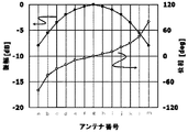
本実施形態に係る給電回路540、550が、放射素子510a−510mに供給するエネルギーの励振振幅・位相(給電分布)を図5に示す。図5において、アンテナ番号a−mは、パッチアンテナ600a−600mにそれぞれ対応する。また、図2乃至図4において、パッチアンテナ600aが下方に位置し(地上方向)、パッチアンテナ600mが上方に位置する(天頂方向)。
FIG. 5 shows the excitation amplitude and phase (feeding distribution) of energy supplied to the radiating elements 510a to 510m by the feeding
図5において、給電回路540、550により、中心のパッチアンテナ600gに最も大きな振幅の電力が供給され、地上方向および天頂方向に行くに従って給電されるエネルギーの振幅が小さくなる。また、振幅の変化量は、地上方向および天頂方向に行くに従って大きくなるようにする。
In FIG. 5, the
さらに、図5において、給電回路540、550により、中心のパッチアンテナ600gから線対象となるように、天頂方向に行くに従って進み、地上方向に行くに従って遅れる、位相の電力が供給される。また、位相の変化量は、地上方向および天頂方向に行くに従って大きくなる。
Further, in FIG. 5, phase feeding power is supplied by feeding
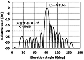
そして、パッチアンテナ600a−600mに図5に示した励振振幅・位相の電力が供給されることにより、本実施形態に係るアンテナ100は、図6に示す放射特性を示す。ここで、図6のElevation Angleθは、図2に示したアンテナ正面での垂直方向の放射角度に対応する。すなわち、Elevation Angleθは、天頂方向が0度、地上方向が180度、水平方向が90度である。
The
図6において、本実施形態に係るアンテナ100の放射特性は、水平方向から上方向の天空サイドローブ(0〜90度)が、25dB以下に押さえられている。また、メインローブの放射角度が92度であり、電気チルト角として2度の角度が初期設定されている。これにより、効率よく基地局側へ偏波を放射することができる。なお、放射パターンのチルト角は、図2において、取り付け金具700を調整してアンテナ100の取付け角度を変えることでも変更できる。
In FIG. 6, the radiation characteristics of the
また、図6において、本実施形態に係るアンテナ100は、水平方向から地上方向(90〜180度)の放射ゲインの減衰パターンがコセカント2乗パターンとなっている。この場合、アンテナ100からの距離に対して、電界強度がほぼ一定となる。
In FIG. 6, the
以上のように、本実施形態において、給電回路540、550のパターンの太さおよび長さを調整することにより、図5に示した振幅・位相をパッチアンテナ600a−600mに供給する。すなわち、中心のパッチアンテナgを最大値とする線対象の振幅を設定し、地上方向および天頂方向に行くに従って供給する電力の振幅を小さくする。また、中心のパッチアンテナgを中心に点対称の位相を設定し、天頂方向に向かって進ませ、地上方向に向かって遅らせる。さらに、振幅および位相の変化量は、地上方向および天頂方向に行くに従って大きくする。パッチアンテナ600a−600mに上述の励振振幅・位相の電力を供給することにより、図6に示すように、アンテナ100が、天空方向の放射が抑圧され、地上方向にコセカント2乗カーブとなる放射パターンを有すると共に、高い放射ゲインを維持しつつ電気チルトを有するようになる。
As described above, in this embodiment, the amplitude and phase shown in FIG. 5 are supplied to the
なお、本実施形態では、放射素子300a−300mおよび放射素子510a−510mで構成されるアンテナ素子として、丸形状のパッチアンテナを適用したが、これに限定されない。例えば、四角形状のパッチアンテナを適用することもできるし、ダイポールアンテナ、スロットアンテナ等のアンテナ素子を適用することもできる。
In the present embodiment, the round patch antenna is applied as the antenna element including the radiating
また、本実施形態では、パッチアンテナに、給電回路540によって水平方向から給電し、給電回路550によって垂直方向から給電することにより、アンテナ100から垂直偏波と水平偏波とを同時に放射または受波したが、これに限定されない。例えば、給電回路540または給電回路550のどちらか一方だけを用い、垂直偏波または水平偏波のどちらか一方のみを扱うこともできる。また、給電ポイント520、530の位置を変更することにより、例えば、+45度および−45度の偏波を放射または受波することもできる。さらに、本実施形態に係るアンテナ100は、13個のアンテナ素子を用いたが、アンテナ素子の数は13に限定されない。
In the present embodiment, the patch antenna is fed from the horizontal direction by the
(第2の実施形態の変形例)
第2の実施形態の変形例について説明する。第2の実施形態では、中心のパッチアンテナ600gを最大値として地上方向および天頂方向に行くに従って小さくなる線対象の振幅を設定すると共に中心のパッチアンテナ600gを中心にして天頂方向に向かって進み、地上方向に向かって遅れる点対称の位相を設定し、振幅および位相の変化量を地上方向および天頂方向に行くに従って大きくした(図5)。これにより、アンテナ100の放射特性において、天空方向の放射が抑圧され、地上方向にコセカント2乗カーブとなる放射パターンを有すると共に、高い放射ゲインを維持しつつ電気チルトを有する(図6)。
(Modification of the second embodiment)
A modification of the second embodiment will be described. In the second embodiment, the
ここで、図3に示したアンテナ100の給電回路540、550の線路パターンを変更することにより、パッチアンテナ600a−600mに供給する電力の振幅・位相分布を変更することができる。図5に示した振幅・位相分布をベースに、振幅分布または/および位相分布を変更することにより、アンテナ100の放射特性を目的に応じて調節することができる。
Here, by changing the line pattern of the feeding
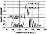
第1の変形例として、振幅分布を変更する場合について説明する。本実施形態に係る振幅・位相分布を図7に、この時のアンテナ100の放射特性を図8に示す。図7に示すように、本実施形態では、第2の実施形態で説明したパッチアンテナ600a−600mに、図5と同様の位相分布の電力を供給するとともに、中心のパッチアンテナ600gを最大値として地上方向および天頂方向に行くに従って一定の割合で小さくなる振幅を給電する。
A case where the amplitude distribution is changed will be described as a first modification. FIG. 7 shows the amplitude / phase distribution according to this embodiment, and FIG. 8 shows the radiation characteristics of the
図6と図8とを比較すると、振幅の変化量を一定値にすることにより、天空サイドローブレベルの抑制がやや低下(最大で約5dB)する一方、足下方向(θ=150度付近)の放射ゲインが高くなる。この場合、基地局の足下付近の電界強度の低下を低減することができる。 Comparing FIG. 6 and FIG. 8, by setting the amount of change in the amplitude to a constant value, the suppression of the sky sidelobe level is slightly reduced (up to about 5 dB), while in the foot direction (around θ = 150 degrees). Radiation gain increases. In this case, it is possible to reduce a decrease in electric field strength near the base station.
次に、第2の変形例として、位相分布を変更する場合について説明する。本実施形態に係る振幅・位相分布を図9に、この時のアンテナ100の放射特性を図10に示す。図9に示すように、本実施形態では、第2の実施形態で説明したパッチアンテナ600a−600mに、図5と同様の振幅分布の電力を供給するとともに、中心のパッチアンテナ600gから天頂方向に向かって位相を大きく進ませ、地上方向に向かって位相を若干遅らせた電力を供給する。なお、位相の変化量は、地上方向および天頂方向に行くに従って大きくする。
Next, a case where the phase distribution is changed will be described as a second modification. FIG. 9 shows the amplitude / phase distribution according to this embodiment, and FIG. 10 shows the radiation characteristics of the
図6と図10とを比較すると、天頂方向に向かって位相を大きく進ませ、地上方向に向かって位相を若干遅らせることにより、メインローブと第1サイドローブとの間の放射特性の落ち込み(第1ヌル)を低減させることができる。第1ヌルがアンテナ100から最も遠い位置において最も広範囲に通信品質の低下等の影響を与えることから、第1ヌルを低減させることにより、通信品質の低下を効率よく改善することができる。
Comparing FIG. 6 and FIG. 10, the phase is greatly advanced toward the zenith direction and the phase is slightly delayed toward the ground direction, so that the radiation characteristics drop between the main lobe and the first side lobe (first 1 null) can be reduced. Since the first null affects the widest range such as a decrease in communication quality at a position farthest from the
さらに、図9では、中心のパッチアンテナ600gから天頂方向に向かって位相を大きく進ませ、地上方向に向かって位相を若干遅らせたが、中心のパッチアンテナ600gから天頂方向に向かって位相を若干進ませ、地上方向に向かって位相を大きく遅らせることでも、第1ヌルを低減させることができる。
Further, in FIG. 9, the phase is greatly advanced from the
第3の変形例として、この場合の振幅・位相分布を図11に、この時のアンテナ100の放射特性を図12に示す。図12の放射特性は、図10の放射特性と同様になる。つまり、図11に示す振幅・位相分布をパッチアンテナ600a−600mに供給することにより、第1ヌルを低減させることができる。
As a third modification, the amplitude / phase distribution in this case is shown in FIG. 11, and the radiation characteristic of the
さらに、図9および図11において、図5に示した振幅分布ではなく図7に示した振幅分布を適用することもできる。すなわち、パッチアンテナ600a−600mに、中心のパッチアンテナ600gを最大値として地上方向および天頂方向に行くに従って一定の割合で小さくなる振幅を給電する。パッチアンテナ600a−600mに、図9または図11に示した位相分布および図7に示した振幅分布の電力を供給することにより、第1ヌルを低減することができると共に足下方向の放射ゲインを高くすることができる。
Furthermore, in FIG. 9 and FIG. 11, the amplitude distribution shown in FIG. 7 can be applied instead of the amplitude distribution shown in FIG. That is, the
なお、本願発明は上記実施形態に限定されるものではなく、この発明の要旨を逸脱しない範囲の設計の変更等があってもこの発明に含まれる。 Note that the present invention is not limited to the above-described embodiment, and any design change or the like within a range not departing from the gist of the present invention is included in the present invention.
10 アンテナ
21、22、…、2n アンテナ素子
30 給電手段
100 アンテナ
200 筐体
300a−300m 放射素子
400a−400m センターポール
500 プリント基板
510a−510m 放射素子
520、530 給電ポイント
540、550 給電回路
600a−600m パッチアンテナ
700 取付金具
800 アンテナ取り付け用ポール
DESCRIPTION OF
Claims (10)
前記アンテナ素子に、前記アレイの両端側に行くに従って低下する振幅、および、一端側に行くに従って進み量が大きくなると共に他端側に行くに従って遅れ量が大きくなる位相を給電する給電手段と、
を備えるアンテナ。 A plurality of antenna elements arranged in an array;
Feeding means for feeding the antenna element with an amplitude that decreases as it goes to both ends of the array, and a phase where the advance amount increases as it goes to one end side and the delay amount increases as it goes to the other end side;
With antenna.
前記振幅および前記位相は、前記アレイの中心に配置されたアンテナ素子を基準に変化する、請求項1乃至5のいずれか1項記載のアンテナ。 The plurality of antenna elements are arranged in an array at equal intervals,
The antenna according to any one of claims 1 to 5, wherein the amplitude and the phase change with reference to an antenna element arranged at the center of the array.
Priority Applications (1)
| Application Number | Priority Date | Filing Date | Title |
|---|---|---|---|
| JP2012143745A JP5983089B2 (en) | 2012-06-27 | 2012-06-27 | Antenna and radio communication apparatus provided with the same |
Applications Claiming Priority (1)
| Application Number | Priority Date | Filing Date | Title |
|---|---|---|---|
| JP2012143745A JP5983089B2 (en) | 2012-06-27 | 2012-06-27 | Antenna and radio communication apparatus provided with the same |
Publications (2)
| Publication Number | Publication Date |
|---|---|
| JP2014007687A true JP2014007687A (en) | 2014-01-16 |
| JP5983089B2 JP5983089B2 (en) | 2016-08-31 |
Family
ID=50105028
Family Applications (1)
| Application Number | Title | Priority Date | Filing Date |
|---|---|---|---|
| JP2012143745A Expired - Fee Related JP5983089B2 (en) | 2012-06-27 | 2012-06-27 | Antenna and radio communication apparatus provided with the same |
Country Status (1)
| Country | Link |
|---|---|
| JP (1) | JP5983089B2 (en) |
Cited By (1)
| Publication number | Priority date | Publication date | Assignee | Title |
|---|---|---|---|---|
| JP6175542B1 (en) * | 2016-06-15 | 2017-08-02 | 有限会社Nazca | Antenna device |
Citations (10)
| Publication number | Priority date | Publication date | Assignee | Title |
|---|---|---|---|---|
| JPH02156706A (en) * | 1988-12-08 | 1990-06-15 | Mitsubishi Electric Corp | Antenna system |
| JPH08340211A (en) * | 1995-06-12 | 1996-12-24 | Sumitomo Electric Ind Ltd | Array antenna |
| JPH10308627A (en) * | 1997-05-08 | 1998-11-17 | Nec Corp | Formed beam array antenna |
| JP2005064934A (en) * | 2003-08-14 | 2005-03-10 | Kobe Steel Ltd | Antenna apparatus |
| JP2006197530A (en) * | 2004-07-12 | 2006-07-27 | Nec Corp | Null-fill antenna, omni antenna, and radio apparatus |
| US20060273972A1 (en) * | 2005-06-02 | 2006-12-07 | Chandler Cole A | Millimeter wave electronically scanned antenna |
| JP2008053953A (en) * | 2006-08-23 | 2008-03-06 | Ntt Docomo Inc | Array antenna and base station |
| JP2009218677A (en) * | 2008-03-07 | 2009-09-24 | Nec Corp | Antenna apparatus, feed circuit, and radio wave transmitting and receiving method |
| US20090305710A1 (en) * | 2008-05-02 | 2009-12-10 | Spx Corporation | Super Economical Broadcast System and Method |
| WO2011024722A1 (en) * | 2009-08-25 | 2011-03-03 | 日本電気株式会社 | Antenna device |
-
2012
- 2012-06-27 JP JP2012143745A patent/JP5983089B2/en not_active Expired - Fee Related
Patent Citations (10)
| Publication number | Priority date | Publication date | Assignee | Title |
|---|---|---|---|---|
| JPH02156706A (en) * | 1988-12-08 | 1990-06-15 | Mitsubishi Electric Corp | Antenna system |
| JPH08340211A (en) * | 1995-06-12 | 1996-12-24 | Sumitomo Electric Ind Ltd | Array antenna |
| JPH10308627A (en) * | 1997-05-08 | 1998-11-17 | Nec Corp | Formed beam array antenna |
| JP2005064934A (en) * | 2003-08-14 | 2005-03-10 | Kobe Steel Ltd | Antenna apparatus |
| JP2006197530A (en) * | 2004-07-12 | 2006-07-27 | Nec Corp | Null-fill antenna, omni antenna, and radio apparatus |
| US20060273972A1 (en) * | 2005-06-02 | 2006-12-07 | Chandler Cole A | Millimeter wave electronically scanned antenna |
| JP2008053953A (en) * | 2006-08-23 | 2008-03-06 | Ntt Docomo Inc | Array antenna and base station |
| JP2009218677A (en) * | 2008-03-07 | 2009-09-24 | Nec Corp | Antenna apparatus, feed circuit, and radio wave transmitting and receiving method |
| US20090305710A1 (en) * | 2008-05-02 | 2009-12-10 | Spx Corporation | Super Economical Broadcast System and Method |
| WO2011024722A1 (en) * | 2009-08-25 | 2011-03-03 | 日本電気株式会社 | Antenna device |
Cited By (2)
| Publication number | Priority date | Publication date | Assignee | Title |
|---|---|---|---|---|
| JP6175542B1 (en) * | 2016-06-15 | 2017-08-02 | 有限会社Nazca | Antenna device |
| JP2017225007A (en) * | 2016-06-15 | 2017-12-21 | 有限会社Nazca | Antenna device |
Also Published As
| Publication number | Publication date |
|---|---|
| JP5983089B2 (en) | 2016-08-31 |
Similar Documents
| Publication | Publication Date | Title |
|---|---|---|
| US10910700B2 (en) | Omnidirectional antenna for mobile communication service | |
| CN107210541B (en) | Mobile base station antenna | |
| KR100269584B1 (en) | Low sidelobe double polarization directional antenna with chalk reflector | |
| CA2699752C (en) | Base station antenna with beam shaping structures | |
| US5629713A (en) | Horizontally polarized antenna array having extended E-plane beam width and method for accomplishing beam width extension | |
| US6067054A (en) | Method and arrangement relating to antennas | |
| US20100007573A1 (en) | Multibeam antenna | |
| KR20120088851A (en) | Mimo antenna | |
| KR20140069968A (en) | Antenna of mobile communication station | |
| JP6195080B2 (en) | Antenna device | |
| Hwang et al. | Cavity-backed stacked patch array antenna with dual polarization for mmWave 5G base stations | |
| EP2937933A1 (en) | Low-profile wideband antenna element and antenna | |
| CN111670546B (en) | Antenna system for mobile equipment and mobile equipment | |
| KR101252244B1 (en) | Multi antenna | |
| CN104798253A (en) | Antenna provided with apparatus for extending beam width for mobile communication base station | |
| JP5545375B2 (en) | Antenna device | |
| JP4431893B2 (en) | Horizontally polarized wave / vertically polarized wave diversity antenna | |
| KR101710803B1 (en) | Base Station Antenna Radiator for Isolation of Polarization Diversity | |
| JP5983089B2 (en) | Antenna and radio communication apparatus provided with the same | |
| KR101288237B1 (en) | Patch Antenna for Receiving Circular Polarization and Linear Polarization | |
| US8912969B2 (en) | Directional antenna and radiating pattern adjustment method | |
| JP2010074532A (en) | Array antenna | |
| KR100849703B1 (en) | Circular polarization antenna | |
| US11973277B2 (en) | Antenna module and antenna device having the same | |
| KR102293354B1 (en) | Omni-directional antenna for mobile communication service |
Legal Events
| Date | Code | Title | Description |
|---|---|---|---|
| A621 | Written request for application examination |
Free format text: JAPANESE INTERMEDIATE CODE: A621 Effective date: 20150518 |
|
| A977 | Report on retrieval |
Free format text: JAPANESE INTERMEDIATE CODE: A971007 Effective date: 20160317 |
|
| A131 | Notification of reasons for refusal |
Free format text: JAPANESE INTERMEDIATE CODE: A131 Effective date: 20160329 |
|
| A521 | Written amendment |
Free format text: JAPANESE INTERMEDIATE CODE: A523 Effective date: 20160526 |
|
| TRDD | Decision of grant or rejection written | ||
| A01 | Written decision to grant a patent or to grant a registration (utility model) |
Free format text: JAPANESE INTERMEDIATE CODE: A01 Effective date: 20160705 |
|
| A61 | First payment of annual fees (during grant procedure) |
Free format text: JAPANESE INTERMEDIATE CODE: A61 Effective date: 20160718 |
|
| R150 | Certificate of patent or registration of utility model |
Ref document number: 5983089 Country of ref document: JP Free format text: JAPANESE INTERMEDIATE CODE: R150 |
|
| LAPS | Cancellation because of no payment of annual fees |