JP2013517493A - Flow sensor and aerosol delivery device - Google Patents
Flow sensor and aerosol delivery device Download PDFInfo
- Publication number
- JP2013517493A JP2013517493A JP2012549429A JP2012549429A JP2013517493A JP 2013517493 A JP2013517493 A JP 2013517493A JP 2012549429 A JP2012549429 A JP 2012549429A JP 2012549429 A JP2012549429 A JP 2012549429A JP 2013517493 A JP2013517493 A JP 2013517493A
- Authority
- JP
- Japan
- Prior art keywords
- temperature
- sensor
- downstream
- upstream
- aerosol
- Prior art date
- Legal status (The legal status is an assumption and is not a legal conclusion. Google has not performed a legal analysis and makes no representation as to the accuracy of the status listed.)
- Ceased
Links
Images


Classifications
-
- G—PHYSICS
- G01—MEASURING; TESTING
- G01F—MEASURING VOLUME, VOLUME FLOW, MASS FLOW OR LIQUID LEVEL; METERING BY VOLUME
- G01F1/00—Measuring the volume flow or mass flow of fluid or fluent solid material wherein the fluid passes through a meter in a continuous flow
- G01F1/68—Measuring the volume flow or mass flow of fluid or fluent solid material wherein the fluid passes through a meter in a continuous flow by using thermal effects
- G01F1/684—Structural arrangements; Mounting of elements, e.g. in relation to fluid flow
-
- A—HUMAN NECESSITIES
- A61—MEDICAL OR VETERINARY SCIENCE; HYGIENE
- A61B—DIAGNOSIS; SURGERY; IDENTIFICATION
- A61B5/00—Measuring for diagnostic purposes; Identification of persons
- A61B5/08—Detecting, measuring or recording devices for evaluating the respiratory organs
- A61B5/087—Measuring breath flow
- A61B5/0878—Measuring breath flow using temperature sensing means
-
- A—HUMAN NECESSITIES
- A61—MEDICAL OR VETERINARY SCIENCE; HYGIENE
- A61B—DIAGNOSIS; SURGERY; IDENTIFICATION
- A61B5/00—Measuring for diagnostic purposes; Identification of persons
- A61B5/48—Other medical applications
- A61B5/4836—Diagnosis combined with treatment in closed-loop systems or methods
- A61B5/4839—Diagnosis combined with treatment in closed-loop systems or methods combined with drug delivery
-
- A—HUMAN NECESSITIES
- A61—MEDICAL OR VETERINARY SCIENCE; HYGIENE
- A61M—DEVICES FOR INTRODUCING MEDIA INTO, OR ONTO, THE BODY; DEVICES FOR TRANSDUCING BODY MEDIA OR FOR TAKING MEDIA FROM THE BODY; DEVICES FOR PRODUCING OR ENDING SLEEP OR STUPOR
- A61M11/00—Sprayers or atomisers specially adapted for therapeutic purposes
- A61M11/02—Sprayers or atomisers specially adapted for therapeutic purposes operated by air or other gas pressure applied to the liquid or other product to be sprayed or atomised
-
- A—HUMAN NECESSITIES
- A61—MEDICAL OR VETERINARY SCIENCE; HYGIENE
- A61M—DEVICES FOR INTRODUCING MEDIA INTO, OR ONTO, THE BODY; DEVICES FOR TRANSDUCING BODY MEDIA OR FOR TAKING MEDIA FROM THE BODY; DEVICES FOR PRODUCING OR ENDING SLEEP OR STUPOR
- A61M15/00—Inhalators
- A61M15/0065—Inhalators with dosage or measuring devices
-
- A—HUMAN NECESSITIES
- A61—MEDICAL OR VETERINARY SCIENCE; HYGIENE
- A61M—DEVICES FOR INTRODUCING MEDIA INTO, OR ONTO, THE BODY; DEVICES FOR TRANSDUCING BODY MEDIA OR FOR TAKING MEDIA FROM THE BODY; DEVICES FOR PRODUCING OR ENDING SLEEP OR STUPOR
- A61M15/00—Inhalators
- A61M15/0085—Inhalators using ultrasonics
-
- A—HUMAN NECESSITIES
- A61—MEDICAL OR VETERINARY SCIENCE; HYGIENE
- A61M—DEVICES FOR INTRODUCING MEDIA INTO, OR ONTO, THE BODY; DEVICES FOR TRANSDUCING BODY MEDIA OR FOR TAKING MEDIA FROM THE BODY; DEVICES FOR PRODUCING OR ENDING SLEEP OR STUPOR
- A61M15/00—Inhalators
- A61M15/0086—Inhalation chambers
-
- G—PHYSICS
- G16—INFORMATION AND COMMUNICATION TECHNOLOGY [ICT] SPECIALLY ADAPTED FOR SPECIFIC APPLICATION FIELDS
- G16H—HEALTHCARE INFORMATICS, i.e. INFORMATION AND COMMUNICATION TECHNOLOGY [ICT] SPECIALLY ADAPTED FOR THE HANDLING OR PROCESSING OF MEDICAL OR HEALTHCARE DATA
- G16H20/00—ICT specially adapted for therapies or health-improving plans, e.g. for handling prescriptions, for steering therapy or for monitoring patient compliance
- G16H20/10—ICT specially adapted for therapies or health-improving plans, e.g. for handling prescriptions, for steering therapy or for monitoring patient compliance relating to drugs or medications, e.g. for ensuring correct administration to patients
- G16H20/13—ICT specially adapted for therapies or health-improving plans, e.g. for handling prescriptions, for steering therapy or for monitoring patient compliance relating to drugs or medications, e.g. for ensuring correct administration to patients delivered from dispensers
-
- G—PHYSICS
- G16—INFORMATION AND COMMUNICATION TECHNOLOGY [ICT] SPECIALLY ADAPTED FOR SPECIFIC APPLICATION FIELDS
- G16H—HEALTHCARE INFORMATICS, i.e. INFORMATION AND COMMUNICATION TECHNOLOGY [ICT] SPECIALLY ADAPTED FOR THE HANDLING OR PROCESSING OF MEDICAL OR HEALTHCARE DATA
- G16H40/00—ICT specially adapted for the management or administration of healthcare resources or facilities; ICT specially adapted for the management or operation of medical equipment or devices
- G16H40/60—ICT specially adapted for the management or administration of healthcare resources or facilities; ICT specially adapted for the management or operation of medical equipment or devices for the operation of medical equipment or devices
- G16H40/63—ICT specially adapted for the management or administration of healthcare resources or facilities; ICT specially adapted for the management or operation of medical equipment or devices for the operation of medical equipment or devices for local operation
-
- A—HUMAN NECESSITIES
- A61—MEDICAL OR VETERINARY SCIENCE; HYGIENE
- A61M—DEVICES FOR INTRODUCING MEDIA INTO, OR ONTO, THE BODY; DEVICES FOR TRANSDUCING BODY MEDIA OR FOR TAKING MEDIA FROM THE BODY; DEVICES FOR PRODUCING OR ENDING SLEEP OR STUPOR
- A61M11/00—Sprayers or atomisers specially adapted for therapeutic purposes
- A61M11/005—Sprayers or atomisers specially adapted for therapeutic purposes using ultrasonics
-
- A—HUMAN NECESSITIES
- A61—MEDICAL OR VETERINARY SCIENCE; HYGIENE
- A61M—DEVICES FOR INTRODUCING MEDIA INTO, OR ONTO, THE BODY; DEVICES FOR TRANSDUCING BODY MEDIA OR FOR TAKING MEDIA FROM THE BODY; DEVICES FOR PRODUCING OR ENDING SLEEP OR STUPOR
- A61M15/00—Inhalators
- A61M15/0001—Details of inhalators; Constructional features thereof
- A61M15/0021—Mouthpieces therefor
- A61M15/0025—Mouthpieces therefor with caps
-
- A—HUMAN NECESSITIES
- A61—MEDICAL OR VETERINARY SCIENCE; HYGIENE
- A61M—DEVICES FOR INTRODUCING MEDIA INTO, OR ONTO, THE BODY; DEVICES FOR TRANSDUCING BODY MEDIA OR FOR TAKING MEDIA FROM THE BODY; DEVICES FOR PRODUCING OR ENDING SLEEP OR STUPOR
- A61M15/00—Inhalators
- A61M15/0065—Inhalators with dosage or measuring devices
- A61M15/0068—Indicating or counting the number of dispensed doses or of remaining doses
- A61M15/008—Electronic counters
-
- A—HUMAN NECESSITIES
- A61—MEDICAL OR VETERINARY SCIENCE; HYGIENE
- A61M—DEVICES FOR INTRODUCING MEDIA INTO, OR ONTO, THE BODY; DEVICES FOR TRANSDUCING BODY MEDIA OR FOR TAKING MEDIA FROM THE BODY; DEVICES FOR PRODUCING OR ENDING SLEEP OR STUPOR
- A61M15/00—Inhalators
- A61M15/009—Inhalators using medicine packages with incorporated spraying means, e.g. aerosol cans
-
- A—HUMAN NECESSITIES
- A61—MEDICAL OR VETERINARY SCIENCE; HYGIENE
- A61M—DEVICES FOR INTRODUCING MEDIA INTO, OR ONTO, THE BODY; DEVICES FOR TRANSDUCING BODY MEDIA OR FOR TAKING MEDIA FROM THE BODY; DEVICES FOR PRODUCING OR ENDING SLEEP OR STUPOR
- A61M16/00—Devices for influencing the respiratory system of patients by gas treatment, e.g. mouth-to-mouth respiration; Tracheal tubes
- A61M16/06—Respiratory or anaesthetic masks
-
- A—HUMAN NECESSITIES
- A61—MEDICAL OR VETERINARY SCIENCE; HYGIENE
- A61M—DEVICES FOR INTRODUCING MEDIA INTO, OR ONTO, THE BODY; DEVICES FOR TRANSDUCING BODY MEDIA OR FOR TAKING MEDIA FROM THE BODY; DEVICES FOR PRODUCING OR ENDING SLEEP OR STUPOR
- A61M2205/00—General characteristics of the apparatus
- A61M2205/18—General characteristics of the apparatus with alarm
-
- A—HUMAN NECESSITIES
- A61—MEDICAL OR VETERINARY SCIENCE; HYGIENE
- A61M—DEVICES FOR INTRODUCING MEDIA INTO, OR ONTO, THE BODY; DEVICES FOR TRANSDUCING BODY MEDIA OR FOR TAKING MEDIA FROM THE BODY; DEVICES FOR PRODUCING OR ENDING SLEEP OR STUPOR
- A61M2205/00—General characteristics of the apparatus
- A61M2205/33—Controlling, regulating or measuring
- A61M2205/3368—Temperature
-
- A—HUMAN NECESSITIES
- A61—MEDICAL OR VETERINARY SCIENCE; HYGIENE
- A61M—DEVICES FOR INTRODUCING MEDIA INTO, OR ONTO, THE BODY; DEVICES FOR TRANSDUCING BODY MEDIA OR FOR TAKING MEDIA FROM THE BODY; DEVICES FOR PRODUCING OR ENDING SLEEP OR STUPOR
- A61M2205/00—General characteristics of the apparatus
- A61M2205/35—Communication
- A61M2205/3576—Communication with non implanted data transmission devices, e.g. using external transmitter or receiver
- A61M2205/3592—Communication with non implanted data transmission devices, e.g. using external transmitter or receiver using telemetric means, e.g. radio or optical transmission
-
- A—HUMAN NECESSITIES
- A61—MEDICAL OR VETERINARY SCIENCE; HYGIENE
- A61M—DEVICES FOR INTRODUCING MEDIA INTO, OR ONTO, THE BODY; DEVICES FOR TRANSDUCING BODY MEDIA OR FOR TAKING MEDIA FROM THE BODY; DEVICES FOR PRODUCING OR ENDING SLEEP OR STUPOR
- A61M2205/00—General characteristics of the apparatus
- A61M2205/50—General characteristics of the apparatus with microprocessors or computers
- A61M2205/502—User interfaces, e.g. screens or keyboards
- A61M2205/505—Touch-screens; Virtual keyboard or keypads; Virtual buttons; Soft keys; Mouse touches
-
- A—HUMAN NECESSITIES
- A61—MEDICAL OR VETERINARY SCIENCE; HYGIENE
- A61M—DEVICES FOR INTRODUCING MEDIA INTO, OR ONTO, THE BODY; DEVICES FOR TRANSDUCING BODY MEDIA OR FOR TAKING MEDIA FROM THE BODY; DEVICES FOR PRODUCING OR ENDING SLEEP OR STUPOR
- A61M2205/00—General characteristics of the apparatus
- A61M2205/58—Means for facilitating use, e.g. by people with impaired vision
- A61M2205/581—Means for facilitating use, e.g. by people with impaired vision by audible feedback
-
- A—HUMAN NECESSITIES
- A61—MEDICAL OR VETERINARY SCIENCE; HYGIENE
- A61M—DEVICES FOR INTRODUCING MEDIA INTO, OR ONTO, THE BODY; DEVICES FOR TRANSDUCING BODY MEDIA OR FOR TAKING MEDIA FROM THE BODY; DEVICES FOR PRODUCING OR ENDING SLEEP OR STUPOR
- A61M2205/00—General characteristics of the apparatus
- A61M2205/58—Means for facilitating use, e.g. by people with impaired vision
- A61M2205/582—Means for facilitating use, e.g. by people with impaired vision by tactile feedback
-
- A—HUMAN NECESSITIES
- A61—MEDICAL OR VETERINARY SCIENCE; HYGIENE
- A61M—DEVICES FOR INTRODUCING MEDIA INTO, OR ONTO, THE BODY; DEVICES FOR TRANSDUCING BODY MEDIA OR FOR TAKING MEDIA FROM THE BODY; DEVICES FOR PRODUCING OR ENDING SLEEP OR STUPOR
- A61M2205/00—General characteristics of the apparatus
- A61M2205/58—Means for facilitating use, e.g. by people with impaired vision
- A61M2205/583—Means for facilitating use, e.g. by people with impaired vision by visual feedback
-
- G—PHYSICS
- G01—MEASURING; TESTING
- G01F—MEASURING VOLUME, VOLUME FLOW, MASS FLOW OR LIQUID LEVEL; METERING BY VOLUME
- G01F1/00—Measuring the volume flow or mass flow of fluid or fluent solid material wherein the fluid passes through a meter in a continuous flow
- G01F1/68—Measuring the volume flow or mass flow of fluid or fluent solid material wherein the fluid passes through a meter in a continuous flow by using thermal effects
- G01F1/684—Structural arrangements; Mounting of elements, e.g. in relation to fluid flow
- G01F1/688—Structural arrangements; Mounting of elements, e.g. in relation to fluid flow using a particular type of heating, cooling or sensing element
- G01F1/6888—Thermoelectric elements, e.g. thermocouples, thermopiles
Landscapes
- Health & Medical Sciences (AREA)
- Engineering & Computer Science (AREA)
- Life Sciences & Earth Sciences (AREA)
- Public Health (AREA)
- General Health & Medical Sciences (AREA)
- Biomedical Technology (AREA)
- Veterinary Medicine (AREA)
- Heart & Thoracic Surgery (AREA)
- Animal Behavior & Ethology (AREA)
- Bioinformatics & Cheminformatics (AREA)
- Hematology (AREA)
- Anesthesiology (AREA)
- Pulmonology (AREA)
- Physics & Mathematics (AREA)
- Medical Informatics (AREA)
- Biophysics (AREA)
- General Physics & Mathematics (AREA)
- Surgery (AREA)
- Medicinal Chemistry (AREA)
- Primary Health Care (AREA)
- Pathology (AREA)
- Fluid Mechanics (AREA)
- Molecular Biology (AREA)
- Chemical & Material Sciences (AREA)
- Epidemiology (AREA)
- Business, Economics & Management (AREA)
- General Business, Economics & Management (AREA)
- Physiology (AREA)
- Pharmacology & Pharmacy (AREA)
- Measuring Volume Flow (AREA)
- Infusion, Injection, And Reservoir Apparatuses (AREA)
- Medicinal Preparation (AREA)
Abstract
エアロゾル送達システム(例えば、エアロゾル化薬剤を患者に送達するためのネビュライザ又はMDI)は、当該システムのエアロゾル出力経路に温度センサを含む。コントローラは、センサが経路内の予め定められた温度変化を検知するとき、システムのエアロゾル発生器がエアロゾルを放出したと決定する。温度センサは、ヒーターと上流の温度センサ及び下流の温度センサとを含む熱フローセンサも有する。コントローラは、経路内の流体の流れの存在、方向及び/又は大きさを決定するために、上流の温度と下流の温度とを比較する。コントローラは、システムの所望の使用の遵守を監視し、及び/又はシステムの適正な使用のためユーザにリアルタイムの指示を供給するために、エアロゾル検出及び/又は流れ検出を使用する。コントローラは、後の分析のためエアロゾル化及び流れデータを記録する。 An aerosol delivery system (eg, a nebulizer or MDI for delivering an aerosolized drug to a patient) includes a temperature sensor in the aerosol output path of the system. The controller determines that the aerosol generator of the system has released aerosol when the sensor detects a predetermined temperature change in the path. The temperature sensor also has a thermal flow sensor that includes a heater and an upstream temperature sensor and a downstream temperature sensor. The controller compares the upstream temperature with the downstream temperature to determine the presence, direction and / or magnitude of the fluid flow in the path. The controller uses aerosol detection and / or flow detection to monitor adherence to the desired use of the system and / or provide real-time instructions to the user for proper use of the system. The controller records aerosolization and flow data for later analysis.
Description
本発明は、概して、例えば、患者の気道にエアロゾルを送達するために用いられるエアロゾル送達システム(例えば、定量吸入器(MDI)及びネビュライザ)の経路を通る流体の流れ及び/又はエアロゾルの存在を検知することに関する。 The present invention generally detects fluid flow and / or the presence of an aerosol through the path of an aerosol delivery system (eg, metered dose inhaler (MDI) and nebulizer) used, for example, to deliver aerosol to the patient's respiratory tract. About doing.
嚢胞性線維症、喘息及びCOPDのような呼吸器疾患は、しばしば呼吸系への直接のエアロゾル(微細な霧)の形式での薬物の送達により治療される。このエアロゾル化薬剤送達は、定量吸入器(MDI)及びネビュライザのようなエアロゾル送達システムにより、広く促進されている。 Respiratory diseases such as cystic fibrosis, asthma and COPD are often treated by delivery of the drug in the form of an aerosol (fine mist) directly to the respiratory system. This aerosolized drug delivery is widely facilitated by aerosol delivery systems such as metered dose inhalers (MDI) and nebulizers.
MDIは、通常は、一つ以上の薬物、噴霧剤及びしばしば安定賦形剤を含む加圧容器及びアクチュエータ/エアロゾル発生器を含む。製剤は、アクチュエータに取り付けられたバルブを通じてエアロゾル化される。1つの容器は、薬物を数百定量まで含む。投薬に依存して、各動作は、通常は25から100マイクロリットルの間のボリュームで送達される数マイクログラムからミリグラムまでの活性成分を含む。MDIの使いやすさ及び効果を改良するために、エアロゾルが患者に到達するために通過するスペーサが加えられる。MDIのオペレーションは、通常は3つのステップを含む。第1に、MDIは薬を噴霧剤及び賦形剤と混ぜるためにシェイクされる。第2に、ボーラスが、容器を押圧することにより、スペーサにリリース(放出)される。第3のステップでは、薬が吸入される。 An MDI typically includes a pressurized container and an actuator / aerosol generator containing one or more drugs, a propellant and often a stable excipient. The formulation is aerosolized through a valve attached to the actuator. One container contains up to hundreds of drugs. Depending on the dosage, each operation contains from a few micrograms to milligrams of active ingredient delivered in a volume typically between 25 and 100 microliters. In order to improve the ease and effectiveness of MDI, a spacer is added through which the aerosol passes to reach the patient. MDI operations typically include three steps. First, the MDI is shaken to mix the drug with the propellant and excipients. Second, the bolus is released (released) into the spacer by pressing the container. In the third step, the drug is inhaled.
ネビュライザは、通常、マウスピースと、エアー吸入/放出口と、エアロゾル発生器と、液剤を含む流体容器とを有する。加えて、ネビュライザは、呼吸パターンを検知するための圧力又はフローセンサを有する。一例として、Respironics社のI−nebネビュライザでは、エアロゾルは、メッシュを通じて薬剤を押している高周波(超音波)で振動するピストンにより生成される。I−nebでのエアロゾル生成は、連続的ではなく、圧力センサにより供給される情報に基づいて、呼吸パターンに適応している。これは、治療を最適化し、薬物を無駄にすることを回避するためである。容器が空になった後、処置は通常終わる。 A nebulizer typically has a mouthpiece, an air inlet / outlet, an aerosol generator, and a fluid container containing a liquid agent. In addition, the nebulizer has a pressure or flow sensor for detecting the breathing pattern. As an example, in the Respironics I-neb nebulizer, the aerosol is generated by a high-frequency (ultrasonic) piston that pushes the drug through the mesh. The aerosol generation at I-neb is not continuous but adapts to the breathing pattern based on information supplied by the pressure sensor. This is to optimize treatment and avoid wasting drug. After the container is emptied, the procedure is usually finished.
本発明の1つ以上の実施例は、上流及び下流の方向を規定するベースと、ベース上に配置されたヒーターと、第1の位置で第1の温度を検知するために配置された第1の温度センサと、ヒーターから下流にベースの下流の温度を検知するためにヒーターの下流のベース上に配置された下流の温度センサとを含む熱フローセンサを提供する。これら温度センサ及びヒーターは、下流方向にベースを通る流体の流れが第1の温度と下流の温度との間の温度差を増大させるように互いに対して位置される。 One or more embodiments of the present invention include a base defining upstream and downstream directions, a heater disposed on the base, and a first disposed to sense a first temperature at a first location. And a downstream temperature sensor disposed on the base downstream of the heater to sense the downstream temperature of the base downstream from the heater. The temperature sensor and the heater are positioned relative to each other such that fluid flow through the base in the downstream direction increases the temperature difference between the first temperature and the downstream temperature.
これらの実施例の一つ以上によると、温度差の大きさは、ベースを通る流体のフローレートの大きさに比例する。 According to one or more of these embodiments, the magnitude of the temperature difference is proportional to the magnitude of the fluid flow rate through the base.
これらの実施例の一つ以上によると、第1の温度センサは、ヒーターから上流のベースの上流の温度を検知するためにヒーターの上流のベース上に配置される上流の温度センサを有する。 According to one or more of these embodiments, the first temperature sensor has an upstream temperature sensor disposed on the base upstream of the heater to sense the temperature upstream of the base upstream from the heater.
これらの実施例の一つ以上によると、温度差は下流の温度から上流の温度を引いた差であって、温度差は、流体がベースを通る上流及び下流の方向の一方の方向に流れるとき正であり、流体がベースを通る上流及び下流の方向の他方の方向に流れるとき負である。 According to one or more of these embodiments, the temperature difference is the difference between the downstream temperature and the upstream temperature, and the temperature difference is when the fluid flows in one of the upstream and downstream directions through the base. Positive and negative when fluid flows in the other direction of the upstream and downstream directions through the base.
これらの実施例の一つ以上によると、上流の温度センサとヒーターとの間の上流の距離は、下流の温度センサとヒーターとの間の下流の距離に実質的に等しい。 According to one or more of these embodiments, the upstream distance between the upstream temperature sensor and the heater is substantially equal to the downstream distance between the downstream temperature sensor and the heater.
これらの実施例の一つ以上によると、ヒーターがオンにされ、ベース上に流体の流れがないとき、上流の温度と下流の温度とが実質的に同一であるように、上流の温度センサ及び下流の温度センサが配置される。 According to one or more of these embodiments, when the heater is turned on and there is no fluid flow on the base, the upstream temperature sensor and the upstream temperature sensor and the downstream temperature are substantially the same. A downstream temperature sensor is arranged.
これらの実施例の一つ以上によると、これら温度センサ及びヒーターは、下流方向の流体の流れが上流の温度に対して下流の温度を増大させるように、互いに対して配置される。 According to one or more of these embodiments, the temperature sensor and heater are positioned relative to each other such that the downstream fluid flow increases the downstream temperature relative to the upstream temperature.
これらの実施例の一つ以上によると、これら温度センサ及びヒーターは、上流方向にベースを通る流体の流れが下流の温度に対して上流の温度を増大させるように、互いに対して配置される。 According to one or more of these embodiments, the temperature sensor and heater are positioned relative to each other such that the fluid flow through the base in the upstream direction increases the upstream temperature relative to the downstream temperature.
これらの実施例の一つ以上によると、ベースはフレームと当該フレームに接続している膜とを有し、フレームは膜より高い熱容量を持ち、ヒーターは膜上に配置され、下流の温度センサはヒーターから下流の膜の温度を検知するために配置され、上流の温度センサはヒーターから上流の膜の温度を検知するために配置される。 According to one or more of these embodiments, the base has a frame and a membrane connected to the frame, the frame has a higher heat capacity than the membrane, the heater is disposed on the membrane, and the downstream temperature sensor is An upstream temperature sensor is arranged to detect the temperature of the film downstream from the heater, and an upstream temperature sensor is arranged to detect the temperature of the film upstream from the heater.
これらの実施例の一つ以上によると、ベースはシリコンフレームと当該シリコンフレームに接続している膜とを有し、シリコンフレームは膜より高い熱容量を持ち、ヒーターは膜上に配置され、下流の温度センサはシリコンフレーム上に配置される基準接合部とヒーターから下流の前記膜上に配置される検知接合部とを持つ熱電対を有し、上流の温度センサはシリコンフレーム上に配置される基準接合部とヒーターから上流の膜上に配置される検知接合部とを持つ熱電対を有する。 According to one or more of these embodiments, the base has a silicon frame and a membrane connected to the silicon frame, the silicon frame has a higher heat capacity than the membrane, the heater is disposed on the membrane, and the downstream The temperature sensor has a thermocouple having a reference junction disposed on the silicon frame and a sensing junction disposed on the membrane downstream from the heater, and the upstream temperature sensor is a reference disposed on the silicon frame. A thermocouple having a junction and a sensing junction disposed on the membrane upstream from the heater.
これらの実施例の一つ以上によると、エアロゾル発生器と、エアロゾル出力開口部と、エアロゾル発生器からエアロゾル出力開口部まで延在する流体経路とを含むエアロゾル送達システムと組み合わせたセンサが使用される。熱フローセンサは、流体経路と熱的に通信される。ベースの下流方向は、エアロゾル出力開口部へ向かって流体経路に沿って向けられる。エアロゾル送達システムは、また、それぞれ上流の温度信号及び下流の温度信号を受信するため上流の温度センサ及び下流の温度センサに接続され、上流の温度と下流の温度とを相関させるコントローラを含む。コントローラは、上流の温度信号と下流の温度信号とを比較することにより流体経路内の流体の流れを検出する。 According to one or more of these embodiments, a sensor is used in combination with an aerosol delivery system that includes an aerosol generator, an aerosol output opening, and a fluid pathway extending from the aerosol generator to the aerosol output opening. . The thermal flow sensor is in thermal communication with the fluid path. The downstream direction of the base is directed along the fluid path toward the aerosol output opening. The aerosol delivery system also includes a controller connected to the upstream temperature sensor and the downstream temperature sensor for receiving the upstream temperature signal and the downstream temperature signal, respectively, and correlating the upstream temperature and the downstream temperature. The controller detects fluid flow in the fluid path by comparing the upstream temperature signal and the downstream temperature signal.
これらの実施例の一つ以上によると、コントローラは、上流の温度信号と下流の温度信号とを比較することにより前記流体経路内の流体の流れの方向を決定する。 According to one or more of these embodiments, the controller determines the direction of fluid flow in the fluid path by comparing an upstream temperature signal and a downstream temperature signal.
これらの実施例の一つ以上によると、コントローラは、前記流体経路内のエアロゾルの存在を検出するために前記センサからの温度センサ信号を使用する。 According to one or more of these embodiments, the controller uses a temperature sensor signal from the sensor to detect the presence of aerosol in the fluid path.
これらの実施例の一つ以上によると、コントローラは、温度センサ信号が予め定められた温度閾値より低い温度を示すとき、エアロゾルが流体経路内に存在すると決定する。 According to one or more of these embodiments, the controller determines that aerosol is present in the fluid path when the temperature sensor signal indicates a temperature below a predetermined temperature threshold.
これらの実施例の一つ以上によると、予め定められた温度閾値は、予め定められた最大フローレートで、エアロゾルがない場合の予め定められた最小の検知温度より低い。 According to one or more of these embodiments, the predetermined temperature threshold is lower than a predetermined minimum detection temperature in the absence of aerosol at a predetermined maximum flow rate.
これらの実施例の一つ以上によると、コントローラは、検知された流体フローレートの関数として、予め定められた温度閾値を変化させる。 According to one or more of these embodiments, the controller changes the predetermined temperature threshold as a function of the sensed fluid flow rate.
本発明の1つ以上の実施例は、フローセンサを通る流体の流れを検出するための方法を提供する。フローセンサは、上流の方向及び下流の方向を規定するベースと、前記ベース上に配置されたヒーターと、第1の位置で第1の温度を検知するために配置される第1の温度センサと、ヒーターから下流のベースの下流の温度を検知するためにヒーターの下流のベース上に配置された下流の温度センサとを含む。方法は、ヒーターに熱を生成させるステップと、第1の温度センサを介して、ベース上の第1の位置で第1の温度を検出するステップと、下流の温度センサを介して、ヒーターから下流のベースの下流の温度を検出するステップと、第1の温度と下流の温度との間の温度差が増大するかどうかを決定することにより、流体がフローセンサを通って流れているかどうかを決定するステップとを含む。 One or more embodiments of the present invention provide a method for detecting fluid flow through a flow sensor. The flow sensor includes a base that defines an upstream direction and a downstream direction, a heater disposed on the base, and a first temperature sensor disposed to detect a first temperature at a first position. A downstream temperature sensor disposed on the base downstream of the heater to sense the temperature downstream of the base downstream from the heater. The method includes causing the heater to generate heat, detecting a first temperature at a first location on the base via a first temperature sensor, and downstream from the heater via a downstream temperature sensor. Detecting whether the fluid is flowing through the flow sensor by detecting a temperature downstream of the base of the base and determining whether the temperature difference between the first temperature and the downstream temperature increases. Including the step of.
これらの実施例の一つ以上によると、方法は、流体が前記フローセンサを通って流れているかどうかの決定をメモリに記録するステップを含む。 According to one or more of these embodiments, the method includes recording in memory a determination of whether fluid is flowing through the flow sensor.
これらの実施例の一つ以上によると、第1の温度と下流の温度との間の温度差が増大するかどうかを決定するステップは、第1の温度センサ及び下流の温度センサの一方からの温度信号から、第1の温度センサ及び下流の温度センサの他方からの温度信号を減算するステップを含む。 According to one or more of these embodiments, the step of determining whether the temperature difference between the first temperature and the downstream temperature is increased is from one of the first temperature sensor and the downstream temperature sensor. Subtracting a temperature signal from the other of the first temperature sensor and the downstream temperature sensor from the temperature signal.
これらの実施例の一つ以上によると、第1の温度と下流の温度との間の温度差が増大するかどうかを決定するステップは、第1の温度センサ及び下流の温度センサの一方からの温度信号を第1の温度センサ及び下流の温度センサの他方からの温度信号により割るステップを含む。 According to one or more of these embodiments, the step of determining whether the temperature difference between the first temperature and the downstream temperature is increased is from one of the first temperature sensor and the downstream temperature sensor. Dividing the temperature signal by the temperature signal from the other of the first temperature sensor and the downstream temperature sensor.
これらの実施例の一つ以上によると、温度差が、上流の温度と下流の温度との間の温度差と相関している測定の単位ユニットに関して検知される。 According to one or more of these embodiments, the temperature difference is detected with respect to a unit of measurement that is correlated with the temperature difference between the upstream temperature and the downstream temperature.
これらの実施例の一つ以上によると、方法は、温度差の大きさから、前記ベースを通る流体のフローレートの大きさを決定するステップを更に含む。 According to one or more of these embodiments, the method further includes determining the magnitude of the fluid flow rate through the base from the magnitude of the temperature difference.
これらの実施例の一つ以上によると、方法は、温度差に基づいてフローセンサを通る流れの方向を決定するステップを更に含む。 According to one or more of these embodiments, the method further includes determining a direction of flow through the flow sensor based on the temperature difference.
これらの実施例の一つ以上によると、第1の温度センサが、ヒーターから上流のベースの上流の温度を検知するためにヒーターの上流のベースに配置されている上流の温度センサを含む。 According to one or more of these embodiments, the first temperature sensor includes an upstream temperature sensor disposed at the base upstream of the heater to sense the temperature upstream of the base upstream from the heater.
これらの実施例の一つ以上によると、上流の温度信号と下流の温度信号とを比較することによりフローセンサを通る流れの方向を決定するステップを更に含み、流れの方向は温度差の符号に基づく。 According to one or more of these embodiments, the method further includes determining a flow direction through the flow sensor by comparing the upstream temperature signal and the downstream temperature signal, the flow direction being a sign of the temperature difference. Based.
これらの実施例の一つ以上によると、ヒーターがオンにされ、ベース上に流体の流れがないとき、上流の温度及び下流の温度が実質的に同一であるように、上流の温度センサ及び下流の温度センサが配置される。 According to one or more of these embodiments, the upstream temperature sensor and the downstream temperature are such that when the heater is turned on and there is no fluid flow on the base, the upstream temperature and downstream temperature are substantially the same. Temperature sensors are arranged.
これらの実施例の一つ以上によると、ベースはフレームと当該フレームに接続される膜とを有し、フレームは膜より高い熱容量を持ち、ヒーターは膜上に配置され、下流の温度センサはヒーターから下流の膜の温度を検知するために配置され、上流の温度センサはヒーターから上流の膜の温度を検知するために配置される。 According to one or more of these embodiments, the base has a frame and a membrane connected to the frame, the frame has a higher heat capacity than the membrane, the heater is disposed on the membrane, and the downstream temperature sensor is the heater The upstream temperature sensor is arranged to detect the temperature of the film downstream from the heater, and the upstream temperature sensor is arranged to detect the temperature of the film upstream from the heater.
これらの実施例の一つ以上によると、ベースはシリコンフレームと当該シリコンフレームに接続される膜とを有し、シリコンフレームは膜より高い熱容量を持ち、ヒーターは膜上に配置され、下流の温度センサはシリコンフレーム上に配置される基準接合部とヒーターから下流の膜上に配置される検知接合部とを持つ熱電対を含み、上流の温度センサはシリコンフレーム上に配置される基準接合部とヒーターから上流の膜上に配置される検知接合部とを持つ熱電対を含む。 According to one or more of these embodiments, the base has a silicon frame and a membrane connected to the silicon frame, the silicon frame has a higher heat capacity than the membrane, the heater is disposed on the membrane, and the downstream temperature The sensor includes a thermocouple having a reference junction disposed on the silicon frame and a sensing junction disposed on the membrane downstream from the heater, and the upstream temperature sensor includes a reference junction disposed on the silicon frame. It includes a thermocouple having a sensing junction disposed on the membrane upstream from the heater.
これらの実施例の一つ以上によると、センサはエアロゾル送達システムの流体経路と熱的に通信し、エアロゾル送達システムは、エアロゾル発生器とエアロゾル出力開口部とを有し、流体経路はエアロゾル発生器からエアロゾル出力開口部まで延在し、ベースの下流方向は前記エアロゾル出力開口部へ向かって流体経路に沿って向いている。 According to one or more of these embodiments, the sensor is in thermal communication with the fluid path of the aerosol delivery system, the aerosol delivery system having an aerosol generator and an aerosol output opening, wherein the fluid path is the aerosol generator. To the aerosol output opening and the downstream direction of the base is directed along the fluid path toward the aerosol output opening.
本発明の様々な実施例のこれら及び他の態様は、動作の方法、構成の関連要素の機能、部品の組合せ及び製造コストと同様に、添付の図面を参照して、下記の説明及び添付の請求の範囲を考慮してもっと明らかになるだろう。これら図面の全てはこの明細書の一部を形成し、類似の参照符号は、それぞれの図の対応する部分を示す。本発明のある実施例において、ここで例示される構成部品は、縮尺通りに描かれている。しかしながら、図面は例示目的であって説明のためであり、本発明の限界を規定するものとして意図されていないことは、明確に理解されるべきである。加えて、本願の任意の実施例に示される又は説明される構成特徴が、同様に他の実施例でも使用できることは理解されるべきである。明細書及び請求項で用いられているように、「a」、「an」及び「the」の単数表記は、明確に示されていない限り複数形を含む。 These and other aspects of the various embodiments of the present invention, as well as the manner of operation, the function of the components involved in the construction, the combination of parts and the manufacturing costs, are described below with reference to the accompanying drawings and It will become more apparent in light of the claims. All of these drawings form part of this specification, and like reference numerals indicate corresponding parts of the respective figures. In certain embodiments of the present invention, the components illustrated herein are drawn to scale. However, it should be clearly understood that the drawings are for illustrative purposes and are for the purpose of illustration and are not intended to define the limits of the invention. In addition, it is to be understood that the structural features shown or described in any embodiment of the present application can be used in other embodiments as well. As used in the specification and claims, the singular forms “a”, “an”, and “the” include plural referents unless the context clearly dictates otherwise.
他の対象物及び他の特徴と同様に、本発明の実施例のより良好な理解のために、添付の図面に関連して使われるべき以下の説明が参照されるだろう。 For a better understanding of the embodiments of the invention, as well as other objects and other features, reference will be made to the following description that is to be used in conjunction with the accompanying drawings.
本発明の様々な実施例によると、エアロゾル送達システム/装置(例えば、MDI100又はネビュライザ200、300(図1乃至図3を参照))は、エアロゾル送達システム内のエアロゾルを検知するセンサ10(例えば、センサ400、500、700、900(図4乃至図6及び図9を参照))及び/又はエアロゾル送達システムを通る流体の流れを検知するセンサ10(例えば、センサ700、900)を含む。エアロゾル送達システム100、200、300は、センサ10に動作的に接続されたコントローラ600も含む。
In accordance with various embodiments of the present invention, an aerosol delivery system / device (eg,
図1乃至図3は、本発明の択一的実施例による様々なエアロゾル送達システムを例示する。 1-3 illustrate various aerosol delivery systems according to alternative embodiments of the present invention.
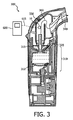
例えば、図1に図示されるように、本発明の実施例によるエアロゾル送達システムは、MDI100を有する。このMDI100の通常の特徴は、米国特許出願公開公報第2004/0231665A1号に説明されていて、その全体の内容は参照によりここに組み込まれる。MDI100は、加圧薬剤の容器120に接続するように構成され設けられたエアロゾル発生器110を含む。ユーザがエアロゾル発生器110へ向けて下方へ容器120を押すとき、エアロゾル発生器110は、容器120からエアロゾル化した薬剤のボーラスをMDI100のスペーサ130へ選択的にリリースすることによりエアロゾルを生成するように構成され設けられる。MDI100は、エアロゾル発生器110からスペーサ130の反対側に配置されたエアロゾル出力開口部140も含む。
For example, as illustrated in FIG. 1, an aerosol delivery system according to an embodiment of the present invention has an
図示された実施例では、MDI100は、スペーサ130を含む。しかしながら、スペーサ130は、本発明の範囲から逸脱することなく省略されてもよい。
In the illustrated embodiment, the
図示された実施例では、エアロゾル出力開口部140は、フェースマスク150を有する。しかしながら、他の任意の適切なエアロゾル出力開口部140(例えば、ストロー状のマウスピース、ベンチレータチューブ等)が、本発明の範囲から逸脱することなく、フェースマスク150の代わりに使われてもよい。
In the illustrated embodiment, the
流体経路160は、エアロゾル発生器110からエアロゾル出力開口部140まで延在する。センサ10は、センサ10が経路160の温度を検知できる位置で、MDI100に取り付けられる。例えば、センサ10は、経路160内(例えば、エアロゾル発生器とスペーサ130との間、スペーサ130内部、スペーサ130とエアロゾル出力開口部140との間)に配置される。センサ10は、代わりに、経路160を規定する壁(例えば、スペーサ130又はエアロゾル発生器110の壁)内又は壁上に配置される。センサ10は、代わりに、センサ10が経路160内の温度変動を速くフォロー(追従)可能にする任意の位置に配置される。
The
図2に図示されるように、本発明の実施例によるエアロゾル送達システムは、ジェットネビュライザ200を有する。このネビュライザ200の通常の特徴は、米国特許出願公開公報第2005/0087189A1号に説明されていて、その全体の内容は参照によりここに組み込まれる。ネビュライザ200は、容器220に保持される流体215をエアロゾル化するために加圧ガスの流れに依存するジェットベースのエアロゾル発生器210を有する。一連の通路230は、エアロゾル発生器210からエアロゾル出力開口部240まで延在し、流体経路260を規定する。図示された実施例では、エアロゾル出力開口部は、マウスピース250を有する。
As illustrated in FIG. 2, an aerosol delivery system according to an embodiment of the present invention includes a
図2に示されるように、センサ10は、センサ10が経路260の温度を検知できる位置で、ネビュライザ200に取り付けられる。例えば、センサ10は、経路260内(例えば、エアロゾル発生器210とエアロゾル出力開口部240との間)に配置される。センサ10は、代わりに、経路260を規定する壁内又は壁上に配置されてもよい。センサ10は、代わりに、センサ10が経路260の温度変動を速くフォロー可能にする位置に配置されてもよい。
As shown in FIG. 2, the
図3に図示されるように、本発明の実施例によるエアロゾル送達システムは、超音波ネビュライザ300を有する。このネビュライザ300の通常の特徴は、米国特許出願公開公報第2007/0277816A1号に説明されていて、その全体の内容は参照によりここに組み込まれる。ネビュライザ300は、ネビュライザ300のエアロゾル発生器310が容器320の流体315をエアロゾル化するためにジェットネビュライザの代わりに超音波トランスデューサ310を有することを除いて、ネビュライザ200と同様である。特に、トランスデューサ310は、超音波エネルギーを流体315に伝播させ、これによって流体315の表面で流体315をエアロゾル化させる。一連の通路330は、エアロゾル発生器310からエアロゾル出力開口部340まで延在し、流体経路360を規定する。ネビュライザ200に関して上述されたように、センサ10は、任意の適切な位置(例えば、経路360内、経路360を規定する壁内又は壁上、センサ10が経路360の温度変動を速くフォロー可能にする位置)に置かれる。
As illustrated in FIG. 3, an aerosol delivery system according to an embodiment of the present invention includes an
代わりの実施例によると、エアロゾル発生器310は、メッシュが振動することで流体の小さな滴をメッシュに通過させることにより流体をエアロゾル化するために、メッシュプレートを振動させる超音波を使用するエアロゾル発生器と置き換えられる。
According to an alternative embodiment, the
図4乃至図6は、エアロゾル送達装置100、200、300のセンサ10として使われる3つの異なる温度センサ400、500、700を例示する。
4-6 illustrate three
図4は、温度センサ400を例示する。センサ400は、抵抗が温度で変化する熱感知抵抗410を有する。抵抗410は、抵抗410のためのベースを作成するためにシリコンフレーム430の開口部間に懸架される膜420に配置されている。よって、抵抗410は、ベースに配置されている(例えば、ベースに取付けられる、ベースと一体的に構成される、ベース内に形成される、ベースに当接する等)。膜420は、膜420及び抵抗410が経路160、260、360の温度変化を速くフォローするような低い(例えば、シリコンフレーム430より低い)熱容量を持つ。
FIG. 4 illustrates a temperature sensor 400. The sensor 400 has a heat
図5は、本発明の代わりの実施例による温度センサ500を例示する。センサ500は、温度を検知する抵抗410の代わりに、熱電対540又は直列の複数の熱電対(別名熱電対列510)を使用する。センサ400の様に、センサ500は、シリコンフレーム530の開口部間に懸架される膜520を有するベースを含む。各熱電対540は、基準接合部540a及び検知接合部540bを含む。基準接合部540aは、シリコンフレーム530上に配置されて、シリコンフレーム530の温度を検知する。検知接合部540bは、膜520上に配置されて、膜520の温度を検知する。膜520がフレーム530より低い熱容量を持つので、膜520は、シリコンフレーム530より非常に速く経路160、260、360内のセンサ500を通る流体の温度変化をフォローする。結果的に、経路160、260、360の温度変化は、シリコンフレーム530と膜520との間の温度差に結果としてなり、そのために、熱電対540は熱電対540上に比例電圧差を生成する。
FIG. 5 illustrates a temperature sensor 500 according to an alternative embodiment of the present invention. The sensor 500 uses a
例示された実施例において、基準接合部540aは、経路160、260、360の温度を(速くはないが)フォローする位置に配置されている。代わりの実施例によると、基準接合部540aは、接合部540aでの温度が経路160、260、360の温度により影響を受けないほど十分に離れて経路160、260、360から間隔を置いて配置される。斯様な間隔は、より正確で、より高いSN比の信号を供給する。しかしながら、斯様な間隔は、生産を複雑にし、さもなければ好ましくはスタンドアローンの統合されたユニットであるセンサ500のコストを増大させる。
In the illustrated embodiment, the reference junction 540a is positioned to follow (but not quickly) the temperature of the
図4及び図5は、本発明の様々な実施例による温度センサ400、500の2つの例を例示する。しかしながら、任意の適切な代わりの温度センサが、本発明の範囲から逸脱することなく、センサ10として、これらのセンサ400、500の代わりに用いられてもよい。例えば、温度センサ10は、温度感知トランジスタ又は赤外線温度センサを有してもよい。温度センサ10は、膜上に位置されるPTAT回路であり、絶対温度に比例する信号を供給する。
4 and 5 illustrate two examples of temperature sensors 400, 500 according to various embodiments of the present invention. However, any suitable alternative temperature sensor may be used in place of these sensors 400, 500 as
図7に示されるように、コントローラ600は、プロセッサ610、視覚的ディスプレイ620、音声出力装置630、メモリ640、ユーザ入力デバイス650及び触覚出力装置660を有する。しかしながら、本発明の様々な実施例によると、これらのコントローラ600の部品の一つ以上(例えば、ディスプレイ620、メモリ640、音声出力装置630、ユーザ入力デバイス650及び/又は触覚出力装置660)は、本発明の範囲から逸脱することなく省略されてもよい。
As shown in FIG. 7, the
図1乃至図3に図示されるエアロゾル送達システム100、200、300に戻ると、温度センサ400、500の形式のセンサ10は、適切なワイヤ615(又は、無線通信のような他のデータ伝送手段(例えば、無線送信、帰納的なデータ伝送等))を介して図7に示されるように動作的にコントローラ600と接続する。コントローラ600は、センサ400、500から経路160、260、360の温度と相関する温度信号を受信するために、センサ400、500と接続する。例えば、抵抗センサ400において、抵抗の抵抗値が温度信号であるように、温度はセンサ400の抵抗410の抵抗値と相関している。従って、コントローラ600は、抵抗410間の抵抗を測定することにより、抵抗410での温度を決定できる。熱電対ベースのセンサ500において、温度(特に基準接合部540aと検知接合部540bとの間の温度差)は、電圧が温度信号であるように、熱電対列510の熱電対540により生成される電圧と相関している。従って、コントローラは、熱電対540及び熱電対列510間の電圧を測定することにより、検知接合部540bで(基準接合部540aに対する)温度を決定できる。
Returning to the
後述されるように、コントローラ600は、流体経路160、260、360のエアロゾルの存在を検知するために、検知された温度/温度信号(例えば、センサ400の抵抗410の抵抗値、センサ500の熱電対列510の電圧)を使用するために構成され設けられる。
As described below, the
図1に示されるように、エアロゾル発生器110は、スペーサ130へのエアロゾル化した薬剤のボーラスをリリースするとき、放出されたガスの膨張及びボーラスの揮発性の噴霧剤成分の急速な蒸発のため、経路160の温度が落ちる。例えば、エアロゾルのボーラスの小さな滴は、滴の大きい全体の表面及び噴霧剤の低い沸点のため、急速に蒸発する。蒸発が吸熱性プロセスであるので、エアロゾルはその周囲からエネルギーを取り出し、これにより周囲、特に経路160、260、360のガスの温度を減少させる。結果的に、エアロゾル発生器110、210、310の下流の経路160、260、360の温度は、このエアロゾルが通ると減少する。温度センサ10、400、500は、この温度低下を検知する。
As shown in FIG. 1, when the
図7に示されるように、コントローラ600のプロセッサ610は、センサ10、400、500と動作的に接続し、ボーラスのリリース又は経路160、260、360内のエアロゾルの存在から生じる温度低下を監視する。
As shown in FIG. 7, the
ある実施例によると、コントローラ600は、センサ500を監視し、温度信号が予め定められた閾値(例えば、1.0a.u.)を超えるとき、ボーラスがリリースされたことを決定する。センサ500において、センサ信号の大きさは、膜520とシリコンフレーム530との間に温度差に比例している。エアロゾルが存在し、膜の比較的低い熱容量のため、シリコンフレーム530より急速に膜520をクールダウンするとき、膜520とシリコンフレーム530との間にかなりの温度差があるだろう。
According to one embodiment, the
上述のセンサ500は、絶対温度よりもむしろ膜520とフレーム530との間の温度差を検知するので、周囲温度に鈍感である。例えば、センサ500が冷えた周囲環境又は熱い周囲環境で用いられるかにかかわらず、センサ500が温度を等しくするために膜520に対する周囲温度の変化とフレーム530に対する周囲温度の変化との間で十分な時間を与えられる限り、センサ500は、温度差を生じさせる経路160、260、360のイベント(例えば、エアロゾルの存在)がない場合に温度差を検知しない。
The sensor 500 described above is insensitive to ambient temperature because it detects the temperature difference between the
温度センサ、例えばセンサ400又は水銀若しくはバイメタリックベースの温度計の一つ以上の実施例によると、エアロゾル送達システム100、200、300が使われる前にコントローラ600がすぐにオンされるとき、コントローラ600はベースライン温度を確立する。コントローラ600は、この検知された最初のベースライン温度をそのメモリ640に保存し、その後検知される温度がベースライン温度より予め定められた閾値より離れている(例えば、より冷たい)とき、エアロゾルが存在すると決定する。
According to one or more embodiments of a temperature sensor, such as sensor 400 or a mercury or bimetallic based thermometer, when the
代わりの実施例によると、コントローラ600は、コントローラが経路160の急速な温度低下を検出するとき、ボーラスがリリースされたと決定する。例えば、プロセッサ610は、温度低下の時系列レートが予め定められた閾値を超える場合、ボーラスがリリースされたと決定する。例えば、プロセッサ610は、予め定められた閾値より大きな温度信号低下が所定の時間枠内で発生する場合、ボーラスがリリースされたと決定する。様々な実施例によると、温度低下閾値(例えば、抵抗410の抵抗値変化、熱電対列510の電圧変化)は、少なくとも1、2、3、4、5、6、7、8、9、10、11、12、13、14、又は15℃程度の温度低下に相関する。様々なこれらの実施例によると、温度低下閾値を検出するための所定の時間枠は、0.1、0.5、1、2、3、4、5、6、7、8、9又は10秒未満である。しかしながら、経路160のタイプ、エアロゾル発生器のタイプ、エアロゾルのタイプ、センサ400、500上に予想される流体フローレート、並びに様々な追加及び/又は他の要因に依存して、これらの閾値は、ボーラスリリースのより精密及び/又は正確な検出を容易にするために増大又は低減されてもよい。
According to an alternative embodiment,
プロセッサ610は、プロセッサの任意の適切なタイプである。例えば、プロセッサ610は、集積回路を有する。プロセッサ610は、デジタル又はアナログである。デジタルプロセッサ610の場合、プロセッサ610は、アナログ温度信号をデジタル信号に変換するA/Dコンバータを含む。プロセッサ610は、コンピュータを有する。プロセッサ610は、コンピュータ上のプログラムのオペレーション(例えば、プロセッサ610の様々な機能を実施する実行コードを持つコンピュータ実行可能媒体)を介して、その監視、計算及び他の機能を実施する。プロセッサ610は、本発明の範囲から逸脱することなく、2つ以上のディスクリートプロセッサの組合せを有する。
The
ディスプレイ620は、適切な画像表示の任意のタイプである(例えば、各LEDの意味を示しているコントローラ600上の永続的な指標を持つ一つ以上のLEDインディケータ、テキスト及び/又はグラフィック指標を表示できる液晶画面)。プロセッサ610は、様々な情報を示すために、ディスプレイ620と接続する。例えば、ボーラスがリリースされるたびに、プロセッサ610は、ディスプレイ620を介して視覚的指標を提供する。
The
図7に示されるように、プロセッサ610は、追加的に及び/又は代わりに、ボーラスがリリースされるときを音声出力装置630がユーザに示すようにしてもよい。音声出力装置630は、ノイズ発生装置の適切なタイプ(例えば、スピーカ、ブザー等)である。音声指標は、ユーザにボーラスがリリースされたことを知らせるビープ音でもよい。音声指標は、代わりに、話し言葉でもよい(例えば、「薬物の服用量がリリースされた。」)。
As shown in FIG. 7,
図7に示されるように、視覚的及び聴覚的信号に加えて又は代わりに、コントローラ600は、触覚フィードバック(例えば、ボーラスがリリースされるとき振動する、誤りが検知されるとき振動する等)をユーザに提供するために、触覚指標660(例えば、モーター及びオフセットフライホイールを使用するバイブレータ)を含んでもよい。よって、コントローラ600は、ボーラスがリリースされるとき、患者に音声、視覚及び/又は触覚指標を供給するボーラスリリース指標を提供する。
As shown in FIG. 7, in addition to or instead of visual and audible signals, the
プロセッサ610は、ユーザがボーラスのリリースでシステム100のこれらの使用を調整するのに役立つために用いられる。例えば、プロセッサ610がボーラスリリースを検出した後の所定時間に、プロセッサ610は、患者がエアロゾル出力開口部140を通じて吸入しなければならないという視覚的指標(ディスプレイ620を介して)、音声指標(音声出力装置630を介して)及び/又は触覚指標(触覚出力装置660を介して)を提供する。所定時間は、任意の適切な時間(例えば、0秒、1秒、2秒)である。例えば、ボーラスがリリースされたことを決定した後の所定の時間に、プロセッサ610は、音声出力装置630によって、「すぐにマウスピースによって吸入せよ」とユーザに向けて言わせる。
The
プロセッサ610は、リリースされるボーラスの数を計数するインクリメントカウンタ機能を持つ。プロセッサ610は、ディスプレイ620により、視覚的に、リリースされるボーラスの数を示す。プロセッサ610は、メモリ640と接続し、プロセッサ610及びセンサ10を介して得られた情報を格納するためにメモリ640を使用する。例えば、メモリ640は、リリースされるボーラスのインクリメントされた数を保存するために用いられる。プロセッサ610は、時刻/日付クロックも含み、リリースの時間及び日付とボーラスリリースとを結びつける機能を含む。プロセッサ610は、この記録された時刻/日付/リリースデータをメモリ640に格納する。プロセッサ610は、ディスプレイ620に斯様な情報を表示させる。例えば、プロセッサ610は、ディスプレイ620に最後のボーラスリリースの時間及び/又は日付を示させる。斯様な履歴データは、患者がシステム100の使用の経過を追跡し、次にシステム100を使用しなければならないときを知るのに役立つ。プロセッサ610自身は、患者がいつ次の薬物用量を受けなければならないかを追跡し、次の用量のための時間であるとき、患者に視覚的、聴覚的及び/又は触覚的指標を供給する。
The
図7に示されるように、コントローラ600は、プロセッサ610に接続されたユーザ入力デバイス650を含む。ユーザ入力デバイス650は、ユーザが情報をコントローラ600に供給可能にするための任意の適切な装置を有する。例えば、ユーザ入力デバイス650は、キーパッド又はキーボードのような一つ以上のボタンを有する。ユーザ入力デバイス650は、ディスプレイ620に組み込まれるタッチスクリーン入力装置を有する。ユーザ入力デバイス650のボタン/スイッチの1つは、コントローラ600用のオン/オフスイッチである。
As shown in FIG. 7, the
ユーザ入力デバイス650は、様々な情報をコントローラ600に提供するために用いられる。例えば、ユーザ入力デバイス650は、ユーザが使用済の薬物容器120を新規な容器120と交換するときはいつでも、ユーザが押す計数リセットボタンを持つ。入力装置650を介してリセット信号を受信すると、プロセッサ610は、どれくらい薬物のボーラスが容器120からリリースされたかをカウントすることを再スタートさせるためにカウンタを0にリセットする。
The
プロセッサ610は、容器120がほとんど空であるときをユーザに示し(例えば、カウントが予め定められた閾値を超えるとき指標を供給する)、ユーザが容器120を交換するか又は新しく利用可能な容器を準備させることを知らせるように構成され設けられる。閾値(又は、コントローラ600が適当な閾値を計算できる何らかの他のデータ)は、システム100に取付けられている容器120のタイプに基づいて、ユーザによりユーザ入力デバイス650を介してコントローラ600に入力される。代わりに、コントローラ600は、容器120自体(例えば、容器上のRFID)を介して、斯様な情報を決定してもよい。
The
本発明の代わりの実施例によると、プロセッサ610は、ディスプレイ620に表示されるカウンタをデクリメントさせるために容器120の用量の数に関する情報を使用する。結果的に、カウンタは、ほぼどれくらいの用量が容器120に残っているかを示すだろう。
According to an alternative embodiment of the present invention,
コントローラ600は、発動メカニズムがいつ作動したかをプロセッサ610が決定できるように、エアロゾル発生器110の発動メカニズムに接続する。例えば、コントローラは、ボーラスをリリースするために容器120が押されたときを検出する圧力スイッチを使用する。斯様な発動信号を受信すると、プロセッサ610は、その時、ボーラスが実際にリリースされたかどうかをセンサ10から決定できる。発動メカニズムが駆動されたがボーラスが検知されない場合、プロセッサ610は、故障が起こった(例えば、エアロゾル発生器が故障した、容器120が空である)という視覚的又は聴覚的信号をユーザに提供する。
図2及び図3に示されるように、コントローラ600は、ネビュライザ200、300に関連して同様の機能を供給する。例えば、プロセッサ610は、システム100のボーラスのリリースの検出に関して、上述されたのと同じ態様又は同様の態様で、経路260、360のエアロゾルの存在を検出するために温度信号を使用する。
As shown in FIGS. 2 and 3, the
例えば、エアロゾル発生器210、310が容器220、230から流体をエアロゾル化し始めるとき、エアロゾル化した滴の蒸発は、エアロゾルが存在する経路260、360の温度を速く低下させる。上述されたように、プロセッサ610は、急速な温度低下(例えば、所定時間に予め定められた温度識別閾値を超える温度低下)が検出されるとき、エアロゾルが経路260、360に存在する(したがって、エアロゾル発生器210、310が流体をエアロゾル化している)と決定できる。
For example, when the
これとは逆に、急速な温度増加は、エアロゾル発生器210、310が容器220、230の流体のエアロゾル化を停止したことを示す。プロセッサ610は、この急速な温度上昇を検出することにより、エアロゾル化の停止を検出できる。例えば、プロセッサ610は、急速な温度増加(例えば、所定時間に予め定められた温度識別閾値を超える温度上昇)が検出されるとき、エアロゾル生成が停止したと決定できる。エアロゾル化の停止(経路260、360内で付随して起こるエアロゾルの欠如)を検出するために用いられる温度差及び所定時間は、エアロゾル化の始まりを検出するために用いられる閾値と同じでもよいし異なってもよい。
Conversely, a rapid temperature increase indicates that the
代わりに、コントローラ600は、温度信号からエアロゾル化の開始及び/又は停止を検出するための他の適切な方法(例えば、温度が予め定められた閾値を越えてベースラインの温度から逸脱するときを検出するようなMDI100に関して上述された方法)を使用してもよい。
Instead, the
プロセッサ610は、エアロゾルが経路260、360に存在するとき、視覚的指標(ディスプレイ620を介して)、音声指標(音声出力装置630を介して)及び/又は触覚指標(触覚出力装置660を介して)を提供する。コントローラ600は、エアロゾル発生器210、310が容器220、320内の流体をエアロゾル化し始めるとき、及び/又は容器220、320から流体をエアロゾル化するのを止めるとき(例えば、容器220、320が空になったとき)をユーザに示す。例えば、コントローラ600は、エアロゾルが経路260、360で検出されるとき、患者にエアロゾル出力開口部240、340から吸入するように視覚的に、聴覚的に及び/又は触覚的に命じる。
The
全ての薬物/流体がエアロゾル化されるまで、ネビュライザのための典型的用量が患者にシステム200、300を使用し続けることを要求するので、エアロゾルがエアロゾル発生器210、310によりもはや生成されないことを検出することにより容器220、320が空になったことをプロセッサ610が検出するまで、コントローラ600は、エアロゾル出力開口部240、340を通じて呼吸し続けるようにユーザに示す。コントローラ600は、空になったことが検出されると、ネビュライザ200、300を使用するのを止めるようにユーザに視覚的に、聴覚的に及び/又は触覚的に示す。例えば、音声出力装置630は、「服用は完了した。現在ネビュライザの使用を止める」ことを患者に言葉で教えてもよい。コントローラ600は、空になったことが検出されるとき、エアロゾル発生器210、310を自動的にオフにしてもよい。
The aerosol is no longer generated by the
ここで、用語「空になった」とは、エアロゾル発生器21、310の継続したオペレーションが微々たる量の付加的流体をエアロゾル化するほど(例えば、エアロゾル出力が、充分な流体が容器220、320内にあるときの通常の出力の20%、15%及び/又は10%未満であるほど)、容器220、320の実質的に全てのエアロゾル化可能な流体がエアロゾル化したことを意味する。よって、容器220、320は、幾らか流体が容器220、320内に残っている場合であっても、「空になった」と言える。
Here, the term “empty” means that the continued operation of the
例えば、幾つかのネビュライザは、患者が吸入しているとき又は患者の吸入の所望の部分だけで、薬物をエアロゾル化するために、患者の呼吸サイクルで噴霧化を調整する。斯様なネビュライザでは、プロセッサ610は、エアロゾル発生器210、310が動作しているが、エアロゾルが経路260、360内に依然検出されないときだけ、容器220、320が空になったと決定する。
For example, some nebulizers adjust nebulization in the patient's respiratory cycle to aerosolize the drug when the patient is inhaling or only in the desired portion of the patient's inhalation. In such a nebulizer, the
MDI100と同様に、コントローラ600は、使用データを記録するために、ネビュライザ200、300に関連して用いられる。例えば、プロセッサ610は、ネビュライザ200、300の各使用の時間、日付及び/又は期間をメモリ640に記録する。プロセッサ610は、記録されたデータ(例えば、最後の使用の時間及び/又は日付、次の使用のための予定の時間等)をディスプレイ620に表示する。メモリ640は、記録されたデータの分析を容易にするために、ユーザ又は医療提供者によりアクセス可能である。
Similar to
図1に示される実施例では、コントローラ600は、MDI100の残部に取り付けられる。図2及び図3に示される実施例では、コントローラは、システム200、300と離れているが、接続ワイヤ615を介してシステムにつながれている。本発明の代わりの実施例によると、コントローラ600は、本発明の範囲から逸脱することなく、システム100、200、300の残部と任意の他の適切な物理的関係を持ってもよい(例えば、任意のシステムのハウジングに組み込まれるか、又はシステムの残部から離れている)。
In the embodiment shown in FIG. 1, the
図6は、エアロゾル送達システム100、200、300を含む本発明の様々な実施例に関連したセンサ10として使われる、熱フローセンサ700を例示する。熱フローセンサ700は、上流の温度センサ710、下流の温度センサ715、シリコンフレーム730の開口部間に懸架される膜720を含むベース、膜720上の中心に配置されているヒーター750を有する。
FIG. 6 illustrates a
一つ以上の実施例によると、センサ400、500、700(フレーム430、530、730、膜420、520、720及び様々な電気部品410、510、710、715、750を含む)は、既知のチップ/半導体製造技術を使用して製造される。センサ400、500、700は、「THERMAL FLOW SENSOR INTEGRATED CIRCUIT WITH LOW RESPONSE TIME AND HIGH SENSITIVITY」というタイトルの添付の特許出願に開示される方法を使用して製造され、この全体の内容は参照によりここに組み込まれる。
According to one or more embodiments, sensors 400, 500, 700 (including
ベースは、上流及び下流の方向を規定し、下流方向は、流れ方向矢印により図6に示されている。様々な実施例によると、センサ700は、流体がエアロゾル発生器110、210、310からエアロゾル出力開口部140、240、340の方へ流れるので、センサ700/ベースの下流方向が流体の流れの方向と合わせされるように、経路160、260、360と関連して配置される。換言すれば、ベースの下流方向は、センサ700の下流方向の検知された流れがエアロゾル出力開口部140、240、340へ向かって流体経路160、260、360の流体の流れを示すように(すなわち、患者による吸入を示す)、エアロゾル出力開口部140、240、340へ向かって経路160、260、360に沿って向けられ、対照的に、センサ700の上流方向の検知された流れは、エアロゾル発生器110、210、310へ向かって経路160、260、360の流体の流れを示す(すなわち、呼気ガスがセンサ700を通過するように、センサ700が配置されるシステムの患者による呼気を示す)。
The base defines upstream and downstream directions, which are indicated in FIG. 6 by flow direction arrows. According to various embodiments, the
ヒーター750は、ヒーター750を加熱する電流をコントローラ600から受けるためにコントローラ600と接続する。ヒーター750は、任意の適切なヒーター、例えば、抵抗である。ヒーター750は膜720を加熱し、このことにより、ヒーター750の位置の中心に最大であり、ヒートシンクとして作用するシリコンフレーム730で最小である温度プロフィールを作る。
The
センサ730の動作の間、コントローラ600は、ヒーター750に定電流を印加する。しかしながら、代わりの実施例によると、コントローラ600は、本発明の範囲から逸脱することなく、電流を変化させてもよい。
During operation of
例示される温度センサ710、715は、各々が基準接合部740a及び検知接合部740bを含む複数の熱電対540を各々が有する熱電対列710、715を有する。基準接合部740aは、シリコンフレーム730上に配置され、シリコンフレーム730の温度を検知する。上流の温度センサ710の検知接合部740bは、膜720上に配置され、ヒーター750から上流の位置で膜720の上流の温度を検知する。従って、熱電対列710は、熱電対列710の基準接合部740aのシリコンフレーム730とヒーター750から上流の熱電対列710の検知接合部740bとの間の温度差と比例する電圧の形式で、上流の温度信号を生成する。
The illustrated temperature sensors 710, 715 have thermocouple arrays 710, 715, each having a plurality of
下流の温度センサ715の検知接合部740bは、膜720上に配置され、ヒーター750から下流の位置で膜720の下流の温度を検知する。従って、熱電対列715は、熱電対列715の基準接合部740aのシリコンフレーム730とヒーター750から下流の熱電対列715の検知接合部740bとの間の温度差と比例する電圧の形式で、下流の温度信号を生成する。
The
膜720がフレーム730より低い熱容量を持つので、膜720は、シリコンフレーム730より非常に速く経路160、260、360のセンサ700を通る流体の温度変化をフォローする。結果的に、経路160、260、360の温度変化はシリコンフレーム730と膜720との間の温度差になり、そのために、熱電対740は比例電圧差を生成する。
Because the
一つ以上の実施例によると、膜420、520、720は、経路160、260、360の温度変化を速くフォローする基板(例えば、低い熱容量を持つ物質)を有する。例えば、膜420、520、720は、周囲環境の温度変化に速く反応するように、低い熱容量を持つ物質の比較的薄い層を有する。様々な実施例によると、膜420は、シリコン、窒化ケイ素、シリコン酸化物、ポリイミド、パリレン及び/又はガラスを有する。斯様な特性は、流れ依存的な温度差とヒーター750の消散電力との比を改善する。
According to one or more embodiments, the
図示された実施例では、フレーム430、530、730は、シリコンを有する。しかしながら、フレーム430、530、730は、代わりに、任意の他の適切な物質を有してもよい。一つ以上の実施例によると、フレーム430、530、730は、仮にあったとしても、膜420、520、720よりゆっくり経路160、260、360の温度変化をフォローする物質(例えば、より厚い物質及び/又は膜420、520、720より高い熱容量を持つ物質)を有する。
In the illustrated embodiment, the
様々な実施例において、シリコンフレーム730の上流側と下流側との間の温度変化は、シリコンフレーム730の高い相対的熱拡散係数のため、膜720の上流側と下流側との間の温度差に対して小さい。結果として、シリコンフレーム730の上流側と下流側との間(すなわち、基準接合部704aが配置される)の温度差は、膜720(すなわち、検知接合部740bが配置される)の温度変化より非常に小さく、従って、本発明の一つ以上の実施例によると、無視できる。
In various embodiments, the temperature change between the upstream and downstream sides of the
図6に示されるように、温度センサ710、715は、ヒーター750から、上流、下流それぞれで、熱的に対称に配置される。ヒーター750が膜720上に中心に配置され、膜720の上流及び下流の熱容量及び拡散性がヒーター750に対して対称形である実施例において、上流の温度センサ710とヒーター750との間の上流の距離は、下流の温度センサ715とヒーター750との間の下流の距離に実質的に等しい。
As shown in FIG. 6, the temperature sensors 710 and 715 are arranged thermally symmetrically upstream and downstream from the
センサ710、715の斯様な対称形配置の結果として、センサ700を通った上流/下流方向の流体の流れがない場合、ヒーター750がオンである一方、上流及び下流の温度は(上流及び下流の温度信号と同様に)、互いに(例えば、10、5、4、3、2、又は1℃程度の範囲内で)実質的に等しい。ヒーター750がオンである間、流体がセンサ700を通って下流に流れるとき、流れがヒーター750からの熱を下流へ、上流のセンサ710から下流のセンサ715の方へ押す/運ぶので、下流の温度は上流の温度に対して上昇する。これとは逆に、ヒーター750がオンである間、流体がセンサ700を通って上流に流れるとき、流れが熱を上流へ、下流のセンサ715から上流のセンサ710の方へ押すので、下流の温度は上流の温度に対して下降する。しかしながら、ヒーター750が膜720を加熱するよりも、流れが経路160、260、360及びセンサ700を冷やすので、いずれの方向の流体の流れも絶対的上流及び下流の温度の低下を生じさせることに留意されるべきである。
As a result of such symmetrical arrangement of sensors 710, 715, if there is no upstream / downstream fluid flow through
上流の温度と下流の温度との間の温度差の大きさは、より速い流体フローレートが流れの方向により多くの熱を押す/運ぶので、流体フローレートの大きさに比例するだろう。図示された実施例では、フローセンサ温度差は、実際の上流及び下流の温度と相関している熱電対列710、715の電圧差に関して定められる。フローセンサ温度差の符号は、センサ710、715がヒーター750に対して熱的に対称に配置される実施例において、センサ700を通る流れの方向を示す。例えば、センサ710、715の極性は、検知接合部740bが基準接合部740aより冷たいとき、これらの極性が正の極性電圧となるように設定される場合、フローセンサ温度差(例えば、上流のセンサ710の電圧信号と下流のセンサ715の電圧信号との差として規定される電圧差)は、流れが下流であるとき正の極性を持ち、流れが上流であるとき負の極性を持つだろう。差の絶対値(例えば、電圧の大きさ)は、センサ700を通る絶対のフローレートと(必ずしもそうである必要はないが、通常は非線形に)比例している。
The magnitude of the temperature difference between the upstream temperature and the downstream temperature will be proportional to the magnitude of the fluid flow rate, as the faster fluid flow rate pushes / carrys more heat in the direction of flow. In the illustrated embodiment, the flow sensor temperature difference is defined in terms of the voltage difference across the thermocouple strings 710, 715 that correlate with the actual upstream and downstream temperatures. The sign of the flow sensor temperature difference indicates the direction of flow through the
ヒーター750に対する上流及び下流のセンサ710、715の熱的に対称形の配置は、(a)オフセットのないフローレートの決定(流れがないとゼロ信号を与える)、(b)差信号の符号から流れ方向を決定する能力、(c)上流及び下流のフローレートが差信号の絶対値と同様に相関しているという結果になる。センサ710、715の対称性のため、差信号(例えば、フローレート信号)は、周囲温度の変化に対して鈍感である。これは、熱電対列710、715両方の信号が同じ絶対量で変化するからであり、2つの信号を減算するか又は割るときキャンセルするからである。
The thermally symmetrical arrangement of the upstream and downstream sensors 710, 715 relative to the
センサ710、715が図示のセンサ700のヒーター750から上流及び下流それぞれ対称的に配置されるが、本発明の代わりの実施例による上流のセンサ710が、代わりに配置されてもよい。例えば、下流の流れだけが測定を所望される場合、上流のセンサ710は、ヒーター750から離れて概して影響を受けない経路160、260、360の区域に配置されてもよい。しかしながら、ここで説明される理由のために、一つ以上の実施例によると、センサ710、715の対称形の配置は、とりわけ較正、正確さ及び精度を改善する傾向がある。
Although the sensors 710, 715 are symmetrically arranged upstream and downstream from the
図示の温度センサ710、715は熱電対列を有するが、代わりに温度センサは、本発明の範囲から逸脱することなく、他の任意の適切なタイプの温度センサを有してもよい。 The illustrated temperature sensors 710, 715 have thermocouple strings, but instead the temperature sensors may have any other suitable type of temperature sensor without departing from the scope of the present invention.
特定のフローセンサ700がここで説明されるが、様々な代わりのフローセンサが、本発明の範囲から逸脱することなく、本発明の様々な実施例に関連して使用できる。
Although a
コントローラ600は、様々な態様で熱フローセンサ700を使用するために構成され配置される。図7に示されるように、コントローラ600は、ワイヤ615を介して、センサ10、700に接続される。上述されるように、、コントローラ600は、これらのワイヤ615を介して電流をヒーター750に供給する。コントローラ600は、また、センサ710、715から、それぞれ上流及び下流の温度に相関する上流及び下流の温度信号をそれぞれ受けるためワイヤ615を介してセンサ710、715と接続する。コントローラ600は、上流及び下流の温度信号を比較することにより、経路160、260、360の範囲内で流体の流れを検知するために、上流及び下流の温度信号を比較する。
The
コントローラ600は、上流及び下流の温度/信号を比較することにより、経路160、260、360内の流体の流れの存在及び方向を決定するように構成され設けられる。例えば、コントローラ600は上流及び下流の温度がほぼ等しいと決定する場合、コントローラ600は、経路160、260、360を通る流体の流れがないと決定する。コントローラ600は下流の温度が上流の温度に対して上昇した(又は、様々な熱的に対称の実施例で上流の温度より高い)と決定する場合、コントローラ600(又は、そのプロセッサ610)は、流体がエアロゾル出力開口部140、240、340へ向かって下流に流れていると決定する。これとは逆に、コントローラ600は下流の温度が上流の温度に対して下降する(又は、様々な熱的に対称の実施例で上流の温度より低い)と決定する場合、コントローラ600(又は、そのプロセッサ610)は、流体がエアロゾル発生器110、210、310へ向かって上流に流れていると決定する。
コントローラ600は、任意の適切な態様で上流及び下流の温度/信号を比較する。例えば、コントローラ600は、上流の温度を下流の温度から減算し、流れの方向を決定するために、結果の符号を使用する。ゼロの結果は流体の流れがないことを示している。代わりに、コントローラ600は、上流及び下流の温度/信号を、一方を他方により割ることにより比較し、商が1より大きいか小さいかによって流れの方向を決定する。商が1の場合は流れがないことを示している。
The
コントローラ600は、また、センサ700を通る流体フローレートを決定するために、センサ700を使用する。決定された流体フローレートは、絶対項(例えば、m/秒又はl/秒)である必要はない。むしろ、流体フローレートは、流体フローレートと相関している変数に関して決定され、表されてもよい。例えば、コントローラ600が熱電対列710からの(ボルトに関する)上流の温度信号を熱電対列715からの(ボルトに関する)下流の温度信号から減算する実施例では、結果として生じる流体フローレートは、ボルト(又は、使用される温度センサのタイプに基づく他の任意の適切な絶対値又は相対的なスケール値)で表される。コントローラ600は、様々な(例えば、ボルトに関する)温度差信号を実際のフローレート(例えば、m/秒、l/秒等)と関連付ける予め定められた変換アルゴリズムを介して、センサ700を通る流体の実際の線形フローレート又は経路160、260、360の実際の容量のフローレートを決定する。アルゴリズムが、数学的に計算されるか、又は代わりに、既知のフローレートで温度差信号を決定する制御テストを通じて経験的に生成される。
The
コントローラ600は、また、センサ500の上述した熱電対列510と同様の温度センサとして、センサ700の温度センサ710、715の一方又は両方を使用する。例えば、センサ710、715両方が使用される場合、これらの信号は温度とともに変化する信号を発生させるために加算される。従って、センサ700は、経路160、260、360内のエアロゾルの存在を検出するために、センサ500と同様の態様で使用できる。
The
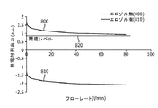
フローセンサ700の動作の間、ヒーター750は膜720を加熱し、膜720はセンサ700を通る気流により冷やされる。図8に図示されるように、膜720の最低気温は最大フローレートで達成され、またこの逆も成立する。図8において、y軸(「熱電対列出力(a.u.)」)は、センサの一つの実施例によるセンサ710、715両方からの累積的な温度信号を表す。x軸は、フローレートを表す。図8に示されるように、累積的な温度信号/累積的な温度は、フローレートに反比例する。ヒーター750が基準接合部740bに対して検知接合部740aを加熱するので、累積的な信号は正である。
During operation of the
図8に示されるように、累積的な温度信号も、エアロゾルの存在で変化する。温度対フローレート曲線800(図8の上位の曲線)は、センサ700が配置される経路にエアロゾルがないときの例示的曲線である。温度対フローレート曲線810(図8の下位の曲線)は、センサ700により検知されるエアロゾルが経路にあるときの例示的曲線である。膜720の温度変化は、ヒーター750で消散される熱量により決定され、例えば、少量の電力は、流れを変化させる温度の小さな変化を与える。エアロゾルが存在するとき、加熱された膜720の温度はクールダウンされるだろう。小さなヒーター750の熱消散に対して、エアロゾルの存在は、エアロゾルがない場合の最大フローレートでの温度より低く膜720を冷やすだろう。換言すれば、他の全ての変数が一定であり、エアロゾルが存在するゼロのフローレートの累積的な温度は、エアロゾルがない場合の最大フローレートでの累積的な温度より低いであろう。閾値レベル820は、エアロゾルがない場合の最大フローレートでの最低の温度よりちょうど下に設定される。温度がこの閾値レベル820より下に下降するとき、エアロゾルによる通過が検出される。図示されたセンサ700では、膜720がシリコンフレーム730より冷たいとき、累積的な温度信号は負である。図示されたセンサ700では、ヒーター750がシリコンフレーム730上のヒーター750から離れた基準接合部740aに対して膜720上のヒーター750の近くでセンサ710、715の検知接合部740bを加熱するので、累積的な温度信号はエアロゾルがない場合正である。
As shown in FIG. 8, the cumulative temperature signal also changes with the presence of aerosol. The temperature versus flow rate curve 800 (upper curve in FIG. 8) is an exemplary curve when there is no aerosol in the path where the
ヒーター750の加熱出力は、競合する変数のバランスをとるために最適化できる。上述されたように、ヒーター750の出力を低減することは、エアロゾルがない場合の速いフローレートと、エアロゾルがある場合の遅いフローレートとを区別することを容易にする。他方では、ヒーター750の出力は、フローレートを検出し定量化するためのセンサの能力のSN比を最適化するために、予想されるフローレートの間、上流の温度と下流の温度との差を最大にするように最適化できる。
The heating output of the
代わりの実施例によると、コントローラ600は、エアロゾルの存在をより正確に検出するために、適応温度閾値820を利用する。図8の曲線800を介して示されるように、エアロゾルが存在しないとき、(シリコンフレームに対する)膜720の累積的な温度信号とフローレートとの間の関係は既知である。コントローラ600が上流の温度信号及び下流の温度信号を比較することにより、上述されたようなフローレートを計算するためにセンサ700を使用できるので、コントローラ600は、累積的な温度信号がエアロゾルがないであろうことを決定するために既知の累積的な温度信号フローレート(エアロゾルがない場合の)関係とともに既知のフローレートを使用できる。従って、コントローラ600は、適応エアロゾル検出温度信号を、エアロゾルがない場合の既知のフローレートで予想される信号より僅かに下にあるように設定できる。コントローラ600は、(温度信号が膜720の温度で上下する実施例において)検知された累積的な温度信号が瞬間的な適応閾値より下降する場合、エアロゾルが存在すると決定する。よって、適応閾値820は、検知されたフローレートで減少するだろう。適応閾値820を使用する一つ以上の実施例によると、実際の膜720の温度と閾値レベル820との差は小さくでき、よって、より小さな温度低下(従って、より小さな量のエアロゾル)が検出できる。また、適応閾値820を使用する一つ以上の実施例によると、適応閾値レベル820は、より高いヒーター750の加熱出力の使用を容易にし、これはガスの流れを検知するセンサの能力のSN比を増大する。適応閾値820を使用する一つ以上の実施例によると、最大フローレートは、閾値レベル820を設定するための最低気温を決定するために定められる必要はない。
According to an alternative embodiment,
図9は、本発明の代わりの実施例による熱フローセンサ900を例示する。センサ900は、本発明の範囲から逸脱することなく、ここで説明されたセンサ400、500、700の何れかの代わりに用いられる。センサ900は、ディスクリート温度センサ910が膜720に加えられて取り付けられる以外は、センサ700と同一である。図示された実施例では、センサ900は、センサ400の上述の抵抗410のような抵抗温度センサである。代わりに、センサ900のようなセンサも、センサ400及びセンサ700両方を実際に使用することにより製造できる。
FIG. 9 illustrates a thermal flow sensor 900 according to an alternative embodiment of the present invention. The sensor 900 may be used in place of any of the
コントローラ600は、コントローラ600がセンサ400の上述した抵抗410と接続するのと同様の態様で、抵抗温度センサ910と接続する。コントローラは、センサ700に関する上述したのと同様の態様で、ヒーター750及びセンサ710、715と接続する。斯様な抵抗温度センサ910の使用は、(熱電対のようなセンサを使用する相対的な温度とは対照的に)センサが絶対温度を測定可能にする。
The
図10は、センサ900を使用して経路内の流れ及び温度を検知するコントローラ600の使用の実験結果を例示する。x軸は、時間を表す。一番上のライン920は、(約5つの十分な呼吸が示される)ユーザの呼吸パターンに対するフローセンサ900の反応を示す。ライン920のy軸は、上流の温度センサ710と下流の温度センサ715との間の温度差(例えば、実際の温度(例えば、摂氏温度)に関する温度信号差(例えば、センサ710、715が熱電対列の場合ボルトであり、抵抗性上流及び下流の温度センサに対してオームである))と相関している。ライン920において、下位の平坦部分は吸入及び呼気の一方を表し、上位の平坦部分は吸入及び呼気の他方を表す(センサ900が上流の温度を下流の温度から減算するように設定されているか又はその逆かに依存する)。エアロゾルがリリースされるとき、小さなスパイク930が、フローセンサ900の信号内に観察され、フローセンサ900がエアロゾルによりほとんど影響を受けないことを示している。
FIG. 10 illustrates experimental results of using a
図10では、下位ライン940は抵抗910(サーミスタとも呼ばれる)により検知される温度と相関しているので、ライン940のy軸は(例えば、実際の温度に関して、オームの抵抗に関して)経路温度と相関している。ライン940の雑音が多いパターンは、流れの変化により生じるヒーター750の温度変動により生じる。エアロゾルがリリースされるとき、抵抗910の抵抗値は、エアロゾルが存在しない場合の最小レベルよりずっと下のレベル950に下降する。センサ700に関して上述されたように、コントローラ600は、プリセット又は適応温度閾値960を利用して、ライン940/温度信号が閾値960を越えるとき、エアロゾルが存在すると決定する。
In FIG. 10, the
代わりの実施例によると、センサ700が用いられ、ディスクリート抵抗910よりむしろヒーター750自体の抵抗値が、センサ900に関して上述されたのと同じ態様で、温度を検知するために用いられる。
According to an alternative embodiment,
熱フローセンサ700、900が、エアロゾル送達装置100、200、300に関連して用いられ、付加的又は代わりの機能をこれらの装置へ供給する。
例えば、MDI100の使用の間、ユーザは、ボーラスの吸入に対するボーラスのリリースを適切に計時しなければならない。種々異なる意図された使用によると、ボーラスがリリースされると(又は、その後の所定の時間後)すぐに患者が吸入する、又は吸入の間にボーラスをリリースすることが所望される。上述されたように、コントローラ600は、エアロゾル化薬剤のボーラスのリリースを検出するために、センサ700、900を使用できる。その上、コントローラ600が経路160内の流れの存在、方向及び/又は大きさを検出するためにセンサ700、900を使用できるので、コントローラ600は、ユーザがエアロゾル出力開口部140を通じて吸入しているときを決定できる。従って、コントローラ600は、所望のリリース/吸入タイミングを患者が遵守することを監視可能であり、及び/又は患者がリリース及び吸入を良好な時間でするのを援助するために患者に指示を供給可能である。
For example, during use of the
モニタリングに関して、コントローラ600は、各ボーラスリリースと各吸入の計時関係(例えば、相対的な開始時間、停止時間、期間)をメモリ640に記録する。この記憶データは、その後、MDI100の所望の使用についての患者の遵守を評価するために、ユーザ又は医学専門家によりアクセスできる。
For monitoring, the
コントローラ600は、リリース/吸入間の検知された関係を予め定められた所望の関係と比較し、患者が適切にリリース及び吸入を計時したかどうかに関する指標を(例えば、ディスプレイ620を介して視覚的に、音声出力装置630を介して聴覚的に、及び/又は触覚出力装置660を介して触覚的に)供給する。患者のタイミングがふさわしくない場合、コントローラ600は、患者が将来所望のタイミングで良好に従うことができるやり方に関する指標(例えば、「次に、エアロゾルをリリースして、すぐに(又は、後で)吸入して下さい」というような視覚的又は聴覚的指標)を提供する。
The
コントローラ600は、追加的に及び/又は代わりに、ボーラスをリリースするべき及び/又は吸入するべき時に関して、リアルタイムの指標を患者に提供する。例えば、ボーラスが患者の吸入の中間(又は、ある他の所望のポイント)でリリースされる場合、コントローラ600がフローセンサ700、900を介して患者が吸入の中間にあることを検出するとき、コントローラ600は、エアロゾル発生器110を起動させるために視覚的、聴覚的又は触覚的指示を供給する。代わりに、コントローラ600がエアロゾル発生器110、210、310をオン又はオフできるような態様で、コントローラ600がエアロゾル発生器110、210、310と接続している実施例では、コントローラ600が患者の検知された呼吸パターンと関連して適当であると決定するとき、コントローラ600自身で、エアロゾル発生器110、210、310をオンにする。
The
代わりに、ボーラスをリリースした後に患者が所定時間吸入することが望ましい場合、コントローラ600は、吸入するための適切なタイミングの視覚的、聴覚的又は触覚的指示を供給する。
Alternatively, if it is desired for the patient to inhale for a predetermined time after releasing the bolus, the
ネビュライザ200、300に関連して、コントローラ600は、MID100に関して上述されたのと同様の態様でフローセンサ700、900を使用する。例えば、コントローラ600は、エアロゾル出力開口部240、340を通じた患者の吸入とエアロゾル発生器210、310によるエアロゾル化の相対的タイミング、時間及び期間を監視し、メモリ640に記録する。このデータは、その後、所望の治療レジメで患者の遵守を評価するために、ユーザ、医療専門家、又は他の適切な人若しくは機械により用いられる。データは、患者に装置200、300を異なって使用するように指示することを正当化し、及び/又は装置200、300が動作するやり方の調整を正当化する(例えば、患者の呼吸パターンに良くマッチするように各エアロゾルリリースの時間及びタイミングを調整することにより、例えば装置自身の動作を調整する)。
In connection with
従来から知られているように、患者の呼吸パターンをネビュライザ200、300によるエアロゾル化と調整することが、しばしば望ましい。例えば、様々なネビュライザは、とりわけ薬物の浪費を減らすために、患者が呼気している時ではなく、患者が吸入しているとき、薬物をエアロゾル化するように設計されている。コントローラ600は、エアロゾル発生器210、310の発動のタイミングをとるために、吸入及び呼気を検知するためフローセンサ700、900をしかるべく使用する。このような実施例では、コントローラ600は、エアロゾル発生器210、310をコントローラがスタート及びストップできるために、エアロゾル発生器210、310と動作的に接続されている。
As is known in the art, it is often desirable to coordinate a patient's breathing pattern with aerosolization by the nebulizers 200,300. For example, various nebulizers are designed to aerosolize drugs when the patient is inhaling rather than when the patient is exhaling, especially to reduce drug waste. The
例としてエアロゾル発生器110、210、310を持つ例としてのエアロゾル送達装置100、200、300が上述されたが、代わりのタイプのエアロゾル送達装置及びエアロゾル発生器が、本発明の範囲から逸脱することなく、これらの例示的装置100、200、300及び/又は生成器110、210、310と置換されてもよい。
Although exemplary
例示の実施例において、センサ10は、エアロゾル送達装置100、200、300の例示的位置に配置される。しかしながら、センサ10は、本発明の範囲から逸脱することなく、他の位置に配置されてもよい。例えば、センサ10は、吸入、呼気及び/又はエアロゾルを検出するセンサの能力を高めるように再位置決めされてもよい。センサ10の位置は、様々な状況を検知する競合する目標のバランスをとるように最適化される。
In the exemplary embodiment,
例えば、図1に図示される装置100では、エアロゾル発生器110の近くにセンサ10を配置することは、エアロゾルの存在を検出するセンサの能力を高める。しかしながら、この位置では、特に呼気バルブがマウスピース140の近くに配置される場合、重要な呼気流がセンサ10に到達しないので、センサ10は、患者呼気を検出できない。代わりに、センサ10は、斯様な吸入/呼気流を検出するために良く適している位置に配置される(例えば、センサ10aとしての図1の模型に示されるように)。しかしながら、センサ10aの設置がエアロゾル発生器110から遠いので、斯様な配置は、エアロゾルを検出するためのセンサ10の感度とのトレードオフを必要とする。
For example, in the
同じ理由から、装置200に関連して図2に示されるセンサ10は、センサ10bとして図2の模型に示されるように再位置決めできる。センサ10bの斯様な配置が患者の呼気及び吸入を検出するセンサの能力を高める一方、センサ10bがエアロゾル発生器210から離れて配置されるので、斯様な配置はエアロゾルの検出に対するセンサの感度を下げる。
For the same reason,
更にまた、一つ以上の実施例では、センサ10は、エアロゾルの存在ではなく、流れを検出するために用いられる。このような実施例では、センサ10は、センサ10のエアロゾルベースの汚れを最小にするためにエアロゾルとのインタラクションを最小にするか又は排除する位置に配置される。例えば、図2のセンサ10cを介した模型に示されるように、センサ10cは、センサ10cの下流に生成されるエアロゾルからの重要な汚れのない吸入を検知するために、エアロゾル発生器210から上流の吸入流体経路に置かれる。同様に、図2のセンサ10dを介した模型に示されるように、センサ10dは、汚れたエアロゾルに対するセンサの露出を制限しながら、患者の呼気を検知する能力を高めるために呼気経路に置かれる。
Furthermore, in one or more embodiments,
図3の装置300のセンサ10に対する同様の代わりの位置は、優先する測定(例えば、エアロゾルの存在、吸入、呼気)に対する感度を改善するために利用される。
Similar alternative locations for the
例示の実施例では、センサ位置10b、10c、10dは、センサ10に対する代わりの位置を提供する。しかしながら、他の実施例によると、装置100、200、300は、複数のセンサ10を使用し、各センサ10が異なる測定に専念する。例えば、装置200では、装置200は、エアロゾルを検出するためのセンサ10、吸入を検出するためのセンサ10c、及び呼気を検出するためのセンサ10dを使用する。
In the illustrated embodiment,
例示の実施例において、エアロゾル送達装置100、200、300は、薬剤をエアロゾル化するように設計されていて、エアロゾル出力開口部140、240、340は、患者の口及び/又はベンチレータチューブを介して患者の気道(例えば、のど、気管支、肺)にエアロゾル化した薬剤の送達を容易にするように設計されている。しかしながら、本発明の代わりの実施例によると、エアロゾル送達システムは、本発明の範囲から逸脱することなく、代わりの機能(例えば、加湿、空気清涼のような香料入りのエアロゾルの拡散)を持ってもよい。加えて又は代わりに、本発明の一つ以上の実施例は、所与の位置でエアロゾルの存在を検知し、及び/又は(流れの存在、流れの方向及び/又は流れの大きさに関して)流体の流れを検知することが望ましい任意のシステムで使われる。例えば、ここで説明されるフローセンサ700、900が、流れを検知するために、ガスパイプラインで使用できる。よって、本発明の様々な実施例は、エアロゾル生成及び/又は送達の状況での使用に限定されない。
In the illustrated embodiment, the
ここで説明される様々な温度センサは、直接(例えば、経路内に配置されるセンサで)、又は間接的に(例えば、センサが壁の温度を検知することにより間接的に経路の温度を検知するように、経路の壁に配置されるセンサで)、経路160、260、360の温度を検知する。
The various temperature sensors described herein can sense the temperature of the path either directly (eg, with a sensor placed in the path) or indirectly (eg, the sensor senses the wall temperature). The temperature of the
ここで使用されているように、温度を検知することは、絶対温度を検知することを必要としない。むしろ、温度を検知することは、単に温度と相関しているあるタイプの信号又は情報を生成することを要求するだけである。例えば、温度測定は、(例えば、熱電対の基準接合部及び検知接合部を介して)基準位置からの温度差に関していてもよい。温度測定は、標準温度単位(例えば、華氏、摂氏、ケルヴィン)に変換される必要はない。むしろ、例えば、抵抗温度センサに対するオーム/抵抗、又は熱電対温度センサに対するボルトに関して温度測定がなされるように、温度測定は、温度と単に(例えば、比例して、逆比例して)相関している。 As used herein, sensing temperature does not require sensing absolute temperature. Rather, sensing temperature simply requires generating some type of signal or information that is correlated with temperature. For example, the temperature measurement may relate to a temperature difference from a reference position (eg, via a thermocouple reference junction and a sensing junction). Temperature measurements need not be converted to standard temperature units (eg, Fahrenheit, Celsius, Kelvin). Rather, the temperature measurement is simply correlated (eg, proportionally, inversely proportionally) to the temperature, such that the temperature measurement is made, for example, in ohms / resistance to a resistance temperature sensor, or in volts to a thermocouple temperature sensor. Yes.
ここで使用されているように、エアロゾル化の開始及び停止という用語は、絶対的ではない。エアロゾル化の開始及び停止はむしろ、エアロゾル化が予め定められた閾値の上又は下にあるとき検出される。例えば、エアロゾル発生器の通常の動作の間、発生するエアロゾル化に対して、エアロゾル化が予め定められた閾値以下(例えば、通常のエアロゾル化の20%、15%、10%未満)に減少するとき、エアロゾル化が停止したと決定されてもよい。 As used herein, the terms aerosolization start and stop are not absolute. Rather, the start and stop of aerosolization is detected when aerosolization is above or below a predetermined threshold. For example, during normal operation of the aerosol generator, for the aerosolization that occurs, the aerosolization is reduced below a predetermined threshold (eg, 20%, 15%, less than 10% of normal aerosolization). Sometimes it may be determined that aerosolization has stopped.
経路160、260、360は、ガス/空気がエアロゾル発生器110、210、310からエアロゾル出力開口部140、240、340まで移動する空間を有する。代わりに、経路160、260、360は、また、ガス/空気がエアロゾル発生器110、210、310からエアロゾル出力開口部140、240、340まで移動する空間を規定する表面でもよい。経路160、260、360は、空間の表面を規定する壁も含む。
前述の例示の実施例は、本発明の構成及び機能的な原理を例示するために提供されていて、限定することを意図していない。反対に、本発明の原理は、以下の請求項の範囲及び要旨内の任意の全ての変化、変更及び/又は置換を含むことを意図する。 The foregoing exemplary embodiments are provided to illustrate the structure and functional principles of the present invention and are not intended to be limiting. On the contrary, the principles of the invention are intended to embrace all such alterations, modifications and / or substitutions that fall within the scope and spirit of the following claims.
Claims (34)
Applications Claiming Priority (3)
| Application Number | Priority Date | Filing Date | Title |
|---|---|---|---|
| US29667810P | 2010-01-20 | 2010-01-20 | |
| US61/296,678 | 2010-01-20 | ||
| PCT/IB2010/055893 WO2011089490A1 (en) | 2010-01-20 | 2010-12-16 | Flow sensor and aerosol delivery device |
Publications (2)
| Publication Number | Publication Date |
|---|---|
| JP2013517493A true JP2013517493A (en) | 2013-05-16 |
| JP2013517493A5 JP2013517493A5 (en) | 2014-02-13 |
Family
ID=44310187
Family Applications (1)
| Application Number | Title | Priority Date | Filing Date |
|---|---|---|---|
| JP2012549429A Ceased JP2013517493A (en) | 2010-01-20 | 2010-12-16 | Flow sensor and aerosol delivery device |
Country Status (6)
| Country | Link |
|---|---|
| US (1) | US20120291779A1 (en) |
| EP (1) | EP2525856A1 (en) |
| JP (1) | JP2013517493A (en) |
| CN (1) | CN102762246A (en) |
| BR (1) | BR112012017664A2 (en) |
| WO (1) | WO2011089490A1 (en) |
Cited By (4)
| Publication number | Priority date | Publication date | Assignee | Title |
|---|---|---|---|---|
| WO2019244323A1 (en) * | 2018-06-22 | 2019-12-26 | 日本たばこ産業株式会社 | Aerosol generating device, and method and program for operating same |
| WO2020090375A1 (en) * | 2018-10-30 | 2020-05-07 | 日本たばこ産業株式会社 | Power supply unit of aerosol generation device, control method of power supply unit of aerosol generation device, and program for power supply unit of aerosol generation device |
| JP2020068690A (en) * | 2018-10-30 | 2020-05-07 | 日本たばこ産業株式会社 | Power supply unit of aerosol generation device, control method of power supply unit of aerosol generation device, and program for power supply unit of aerosol generation device |
| JP2021036881A (en) * | 2020-11-06 | 2021-03-11 | 日本たばこ産業株式会社 | Aerosol generation device, and method and program for operating the same |
Families Citing this family (25)
| Publication number | Priority date | Publication date | Assignee | Title |
|---|---|---|---|---|
| US20130255678A1 (en) * | 2009-07-01 | 2013-10-03 | Microdose Therapeutx, Inc. | Nebulizer for infants and respiratory compromised patients |
| WO2013098397A2 (en) | 2011-12-30 | 2013-07-04 | Philip Morris Products S.A. | Aerosol generating device with air flow detection |
| US9884157B2 (en) * | 2013-03-15 | 2018-02-06 | Microdose Therapeutx, Inc. | Inhalation device, control method and computer program |
| US9700688B2 (en) | 2013-03-15 | 2017-07-11 | Trudell Medical International | Delivery device and kit, and method of use |
| WO2014140774A1 (en) | 2013-03-15 | 2014-09-18 | Trudell Medical International | Delivery device and kit, and method of use |
| US11116914B2 (en) * | 2014-11-09 | 2021-09-14 | Sipnose Ltd. | Device and method for aerosolized delivering of substance to a natural orifice of the body |
| US11471618B2 (en) | 2014-11-09 | 2022-10-18 | Sipnose Ltd. | Adjustable dosing delivery and multi sectioned drug compartment |
| US11278682B2 (en) | 2014-11-09 | 2022-03-22 | Sipnose Ltd. | Device and method for aerosolized delivery of substance to a natural orifice of the body |
| DE202013105715U1 (en) | 2013-08-22 | 2014-02-19 | Sipnose Ltd. | Device for delivering a predetermined amount of a substance to a natural opening of the body |
| US10743793B2 (en) * | 2014-03-10 | 2020-08-18 | Respimetrix Gmbh | Systems and methods for delivering an agent to a user's lungs and for simultaneously monitoring lung health |
| EP3344320B1 (en) * | 2015-08-31 | 2021-03-31 | Vapotherm, Inc. | High flow therapy with built-in oxygen concentrator |
| ES2956026T3 (en) | 2016-03-24 | 2023-12-11 | Trudell Medical Int | Respiratory care system with electronic indicator |
| BR112018070299B1 (en) * | 2016-04-05 | 2023-02-07 | Chiesi Farmaceutici S.P.A. | METHOD OF COUNTING DRUG DOSES ADMINISTERED BY AN INHALER, ELECTRONIC DEVICE, SYSTEM, CONTAINER, INHALER AND COMPUTER PROGRAM |
| EP3458132B1 (en) | 2016-05-19 | 2021-06-30 | Trudell Medical International | Smart valved holding chamber |
| CN116712646A (en) * | 2016-05-27 | 2023-09-08 | 普罗沃锐斯科学有限公司 | Device and method for using a medicament device |
| EP3984579A1 (en) | 2016-07-08 | 2022-04-20 | Trudell Medical International | Smart oscillating positive expiratory pressure device |
| CN109789285B (en) * | 2016-08-05 | 2023-01-20 | 尤尔实验室有限公司 | Wind speed auxiliary control of evaporator |
| US11497867B2 (en) | 2016-12-09 | 2022-11-15 | Trudell Medical International | Smart nebulizer |
| MX2020007026A (en) | 2018-01-04 | 2020-12-03 | Trudell Medical Int | Smart oscillating positive expiratory pressure device. |
| EP3758603A4 (en) * | 2018-03-02 | 2021-12-01 | Singapore Health Services Pte Ltd | Device and method for measuring respiratory air flow |
| EP3801714A4 (en) | 2018-06-04 | 2022-03-09 | Trudell Medical International | Smart valved holding chamber |
| US11865257B2 (en) | 2018-08-07 | 2024-01-09 | Feellife Health Inc. | ICU-special portable nebulization device enabling autonomous respiration according to airflow |
| WO2020168138A1 (en) * | 2019-02-14 | 2020-08-20 | Reciprocal Labs Corporation | Systems and methods for improving respiratory medicament device usage |
| WO2021038467A1 (en) | 2019-08-27 | 2021-03-04 | Trudell Medical International | Smart oscillating positive expiratory pressure device |
| GB2600980B (en) * | 2020-11-14 | 2024-03-06 | Inspired Ventilation Ltd | A breathing system for a patient to breathe through and inhale a substance from |
Citations (4)
| Publication number | Priority date | Publication date | Assignee | Title |
|---|---|---|---|---|
| JP2000515238A (en) * | 1992-04-21 | 2000-11-14 | グラクソ、インコーポレーテッド | Spray inspection method |
| JP2002136595A (en) * | 2000-10-31 | 2002-05-14 | Nippon Applied Flow Kk | Flowmeter for respirator |
| JP2007533411A (en) * | 2004-04-20 | 2007-11-22 | エアロゲン,インコーポレイティド | Aerosol delivery device, method and composition for a pressurized respiratory system |
| JP2008096453A (en) * | 2000-06-23 | 2008-04-24 | Omron Corp | Heating device for sensor, sensor, and acceleration sensor |
Family Cites Families (20)
| Publication number | Priority date | Publication date | Assignee | Title |
|---|---|---|---|---|
| US3931736A (en) * | 1974-06-28 | 1976-01-13 | Rca Corporation | Improved fluid flow sensor configuration |
| US5394866A (en) * | 1991-03-05 | 1995-03-07 | Aradigm Corporation | Automatic aerosol medication delivery system and methods |
| US5404871A (en) * | 1991-03-05 | 1995-04-11 | Aradigm | Delivery of aerosol medications for inspiration |
| JP3175887B2 (en) * | 1992-10-27 | 2001-06-11 | 株式会社半導体エネルギー研究所 | measuring device |
| US6390088B1 (en) * | 1993-12-13 | 2002-05-21 | Boehringer Ingelheim Kg | Aerosol inhaler |
| DE4418207C1 (en) * | 1994-05-25 | 1995-06-22 | Siemens Ag | Thermal sensor or actuator in semiconductor material |
| US5809997A (en) * | 1995-05-18 | 1998-09-22 | Medtrac Technologies, Inc. | Electronic medication chronolog device |
| US8820316B2 (en) | 2000-02-11 | 2014-09-02 | Respironics Respiratory Drug Delivery (Uk) Ltd | Drug delivery apparatus |
| US6871535B2 (en) * | 2002-08-14 | 2005-03-29 | Hewlett-Packard Development Company, L.P. | Flow direction detector |
| EP1426740B1 (en) * | 2002-11-27 | 2014-11-19 | Sensirion Holding AG | Device for measuring the flow and at least one material parameter of a fluid |
| US7748385B2 (en) | 2003-05-23 | 2010-07-06 | Ric Investments, Inc | Valved holding chamber for use with an aerosol medication delivery system |
| JP4359705B2 (en) * | 2003-12-08 | 2009-11-04 | 株式会社日立製作所 | Heating resistance type flow measuring device |
| DE602006019548D1 (en) * | 2006-03-31 | 2011-02-24 | Sensirion Holding Ag | Flow sensor with thermocouples |
| US8991389B2 (en) | 2006-04-20 | 2015-03-31 | Ric Investments, Llc | Drug solution level sensor for an ultrasonic nebulizer |
| US7755466B2 (en) * | 2006-04-26 | 2010-07-13 | Honeywell International Inc. | Flip-chip flow sensor |
| EP1965179B1 (en) * | 2007-02-28 | 2017-04-12 | Sensirion Holding AG | Flow detector device with self check |
| JP4850105B2 (en) * | 2007-03-23 | 2012-01-11 | 日立オートモティブシステムズ株式会社 | Thermal flow meter |
| RU2523820C2 (en) * | 2007-05-30 | 2014-07-27 | Джилберт Якобус КУЙПЕРС | Improvements of electric drive devices for artificial lung ventilation |
| US7908096B2 (en) * | 2007-09-28 | 2011-03-15 | Siargo Ltd. | Integrated micromachined thermal mass flow sensor and methods of making the same |
| US7878056B2 (en) * | 2007-12-19 | 2011-02-01 | Siargo Ltd. | Micromachined thermal mass flow sensor with self-cleaning capability and methods of making the same |
-
2010
- 2010-12-16 CN CN2010800618536A patent/CN102762246A/en active Pending
- 2010-12-16 BR BR112012017664A patent/BR112012017664A2/en not_active IP Right Cessation
- 2010-12-16 EP EP10810797A patent/EP2525856A1/en not_active Withdrawn
- 2010-12-16 US US13/522,798 patent/US20120291779A1/en not_active Abandoned
- 2010-12-16 JP JP2012549429A patent/JP2013517493A/en not_active Ceased
- 2010-12-16 WO PCT/IB2010/055893 patent/WO2011089490A1/en active Application Filing
Patent Citations (4)
| Publication number | Priority date | Publication date | Assignee | Title |
|---|---|---|---|---|
| JP2000515238A (en) * | 1992-04-21 | 2000-11-14 | グラクソ、インコーポレーテッド | Spray inspection method |
| JP2008096453A (en) * | 2000-06-23 | 2008-04-24 | Omron Corp | Heating device for sensor, sensor, and acceleration sensor |
| JP2002136595A (en) * | 2000-10-31 | 2002-05-14 | Nippon Applied Flow Kk | Flowmeter for respirator |
| JP2007533411A (en) * | 2004-04-20 | 2007-11-22 | エアロゲン,インコーポレイティド | Aerosol delivery device, method and composition for a pressurized respiratory system |
Cited By (6)
| Publication number | Priority date | Publication date | Assignee | Title |
|---|---|---|---|---|
| WO2019244323A1 (en) * | 2018-06-22 | 2019-12-26 | 日本たばこ産業株式会社 | Aerosol generating device, and method and program for operating same |
| JPWO2019244323A1 (en) * | 2018-06-22 | 2020-12-17 | 日本たばこ産業株式会社 | Aerosol generator and method and program to operate it |
| US11160312B2 (en) | 2018-06-22 | 2021-11-02 | Japan Tobacco Inc. | Aerosol generating device, and method and program for operating same |
| WO2020090375A1 (en) * | 2018-10-30 | 2020-05-07 | 日本たばこ産業株式会社 | Power supply unit of aerosol generation device, control method of power supply unit of aerosol generation device, and program for power supply unit of aerosol generation device |
| JP2020068690A (en) * | 2018-10-30 | 2020-05-07 | 日本たばこ産業株式会社 | Power supply unit of aerosol generation device, control method of power supply unit of aerosol generation device, and program for power supply unit of aerosol generation device |
| JP2021036881A (en) * | 2020-11-06 | 2021-03-11 | 日本たばこ産業株式会社 | Aerosol generation device, and method and program for operating the same |
Also Published As
| Publication number | Publication date |
|---|---|
| EP2525856A1 (en) | 2012-11-28 |
| US20120291779A1 (en) | 2012-11-22 |
| CN102762246A (en) | 2012-10-31 |
| WO2011089490A1 (en) | 2011-07-28 |
| BR112012017664A2 (en) | 2016-04-19 |
Similar Documents
| Publication | Publication Date | Title |
|---|---|---|
| JP2013517493A (en) | Flow sensor and aerosol delivery device | |
| US20120285236A1 (en) | Method of using a temperature-based aerosol detector | |
| US20130186392A1 (en) | Aerosol delivery system with temperature-based aerosol detector | |
| JP6714657B2 (en) | Inhaler, control method and computer program | |
| US11918736B2 (en) | Method and apparatus to measure, aid and correct the use of inhalers | |
| US20180161531A1 (en) | Smart nebulizer | |
| AU2023204367A1 (en) | Anemometric-assisted control of a vaporizer | |
| US20220260399A1 (en) | Vaporizer flow detection | |
| JP2004512148A (en) | Drug dispenser | |
| EP2991715B1 (en) | Critical care ventilator with mouth piece ventilation | |
| WO2002036181A2 (en) | Piezoelectric polymer flow sensor and methods |
Legal Events
| Date | Code | Title | Description |
|---|---|---|---|
| A521 | Request for written amendment filed |
Free format text: JAPANESE INTERMEDIATE CODE: A523 Effective date: 20131213 |
|
| A621 | Written request for application examination |
Free format text: JAPANESE INTERMEDIATE CODE: A621 Effective date: 20131213 |
|
| RD02 | Notification of acceptance of power of attorney |
Free format text: JAPANESE INTERMEDIATE CODE: A7422 Effective date: 20131213 |
|
| A977 | Report on retrieval |
Free format text: JAPANESE INTERMEDIATE CODE: A971007 Effective date: 20140620 |
|
| A131 | Notification of reasons for refusal |
Free format text: JAPANESE INTERMEDIATE CODE: A131 Effective date: 20140701 |
|
| A521 | Request for written amendment filed |
Free format text: JAPANESE INTERMEDIATE CODE: A523 Effective date: 20140911 |
|
| A01 | Written decision to grant a patent or to grant a registration (utility model) |
Free format text: JAPANESE INTERMEDIATE CODE: A01 Effective date: 20150116 |
|
| A045 | Written measure of dismissal of application [lapsed due to lack of payment] |
Free format text: JAPANESE INTERMEDIATE CODE: A045 Effective date: 20150526 |