JP2013504389A - Disc-shaped orthopedic device - Google Patents
Disc-shaped orthopedic device Download PDFInfo
- Publication number
- JP2013504389A JP2013504389A JP2012528948A JP2012528948A JP2013504389A JP 2013504389 A JP2013504389 A JP 2013504389A JP 2012528948 A JP2012528948 A JP 2012528948A JP 2012528948 A JP2012528948 A JP 2012528948A JP 2013504389 A JP2013504389 A JP 2013504389A
- Authority
- JP
- Japan
- Prior art keywords
- orthopedic
- implant
- dimension
- region
- joint device
- Prior art date
- Legal status (The legal status is an assumption and is not a legal conclusion. Google has not performed a legal analysis and makes no representation as to the accuracy of the status listed.)
- Pending
Links
Images


Classifications
-
- A—HUMAN NECESSITIES
- A61—MEDICAL OR VETERINARY SCIENCE; HYGIENE
- A61F—FILTERS IMPLANTABLE INTO BLOOD VESSELS; PROSTHESES; DEVICES PROVIDING PATENCY TO, OR PREVENTING COLLAPSING OF, TUBULAR STRUCTURES OF THE BODY, e.g. STENTS; ORTHOPAEDIC, NURSING OR CONTRACEPTIVE DEVICES; FOMENTATION; TREATMENT OR PROTECTION OF EYES OR EARS; BANDAGES, DRESSINGS OR ABSORBENT PADS; FIRST-AID KITS
- A61F2/00—Filters implantable into blood vessels; Prostheses, i.e. artificial substitutes or replacements for parts of the body; Appliances for connecting them with the body; Devices providing patency to, or preventing collapsing of, tubular structures of the body, e.g. stents
- A61F2/02—Prostheses implantable into the body
- A61F2/30—Joints
- A61F2/42—Joints for wrists or ankles; for hands, e.g. fingers; for feet, e.g. toes
- A61F2/4241—Joints for wrists or ankles; for hands, e.g. fingers; for feet, e.g. toes for hands, e.g. fingers
-
- A—HUMAN NECESSITIES
- A61—MEDICAL OR VETERINARY SCIENCE; HYGIENE
- A61F—FILTERS IMPLANTABLE INTO BLOOD VESSELS; PROSTHESES; DEVICES PROVIDING PATENCY TO, OR PREVENTING COLLAPSING OF, TUBULAR STRUCTURES OF THE BODY, e.g. STENTS; ORTHOPAEDIC, NURSING OR CONTRACEPTIVE DEVICES; FOMENTATION; TREATMENT OR PROTECTION OF EYES OR EARS; BANDAGES, DRESSINGS OR ABSORBENT PADS; FIRST-AID KITS
- A61F2/00—Filters implantable into blood vessels; Prostheses, i.e. artificial substitutes or replacements for parts of the body; Appliances for connecting them with the body; Devices providing patency to, or preventing collapsing of, tubular structures of the body, e.g. stents
- A61F2/02—Prostheses implantable into the body
- A61F2/30—Joints
- A61F2/46—Special tools or methods for implanting or extracting artificial joints, accessories, bone grafts or substitutes, or particular adaptations therefor
- A61F2/4603—Special tools or methods for implanting or extracting artificial joints, accessories, bone grafts or substitutes, or particular adaptations therefor for insertion or extraction of endoprosthetic joints or of accessories thereof
- A61F2/4606—Special tools or methods for implanting or extracting artificial joints, accessories, bone grafts or substitutes, or particular adaptations therefor for insertion or extraction of endoprosthetic joints or of accessories thereof of wrists or ankles; of hands, e.g. fingers; of feet, e.g. toes
-
- A—HUMAN NECESSITIES
- A61—MEDICAL OR VETERINARY SCIENCE; HYGIENE
- A61F—FILTERS IMPLANTABLE INTO BLOOD VESSELS; PROSTHESES; DEVICES PROVIDING PATENCY TO, OR PREVENTING COLLAPSING OF, TUBULAR STRUCTURES OF THE BODY, e.g. STENTS; ORTHOPAEDIC, NURSING OR CONTRACEPTIVE DEVICES; FOMENTATION; TREATMENT OR PROTECTION OF EYES OR EARS; BANDAGES, DRESSINGS OR ABSORBENT PADS; FIRST-AID KITS
- A61F2/00—Filters implantable into blood vessels; Prostheses, i.e. artificial substitutes or replacements for parts of the body; Appliances for connecting them with the body; Devices providing patency to, or preventing collapsing of, tubular structures of the body, e.g. stents
- A61F2/02—Prostheses implantable into the body
- A61F2/30—Joints
- A61F2002/30001—Additional features of subject-matter classified in A61F2/28, A61F2/30 and subgroups thereof
- A61F2002/30108—Shapes
- A61F2002/3011—Cross-sections or two-dimensional shapes
- A61F2002/30112—Rounded shapes, e.g. with rounded corners
- A61F2002/3013—Rounded shapes, e.g. with rounded corners figure-"8"- or hourglass-shaped
-
- A—HUMAN NECESSITIES
- A61—MEDICAL OR VETERINARY SCIENCE; HYGIENE
- A61F—FILTERS IMPLANTABLE INTO BLOOD VESSELS; PROSTHESES; DEVICES PROVIDING PATENCY TO, OR PREVENTING COLLAPSING OF, TUBULAR STRUCTURES OF THE BODY, e.g. STENTS; ORTHOPAEDIC, NURSING OR CONTRACEPTIVE DEVICES; FOMENTATION; TREATMENT OR PROTECTION OF EYES OR EARS; BANDAGES, DRESSINGS OR ABSORBENT PADS; FIRST-AID KITS
- A61F2/00—Filters implantable into blood vessels; Prostheses, i.e. artificial substitutes or replacements for parts of the body; Appliances for connecting them with the body; Devices providing patency to, or preventing collapsing of, tubular structures of the body, e.g. stents
- A61F2/02—Prostheses implantable into the body
- A61F2/30—Joints
- A61F2002/30001—Additional features of subject-matter classified in A61F2/28, A61F2/30 and subgroups thereof
- A61F2002/30108—Shapes
- A61F2002/3011—Cross-sections or two-dimensional shapes
- A61F2002/30112—Rounded shapes, e.g. with rounded corners
- A61F2002/30136—Rounded shapes, e.g. with rounded corners undulated or wavy, e.g. serpentine-shaped or zigzag-shaped
-
- A—HUMAN NECESSITIES
- A61—MEDICAL OR VETERINARY SCIENCE; HYGIENE
- A61F—FILTERS IMPLANTABLE INTO BLOOD VESSELS; PROSTHESES; DEVICES PROVIDING PATENCY TO, OR PREVENTING COLLAPSING OF, TUBULAR STRUCTURES OF THE BODY, e.g. STENTS; ORTHOPAEDIC, NURSING OR CONTRACEPTIVE DEVICES; FOMENTATION; TREATMENT OR PROTECTION OF EYES OR EARS; BANDAGES, DRESSINGS OR ABSORBENT PADS; FIRST-AID KITS
- A61F2/00—Filters implantable into blood vessels; Prostheses, i.e. artificial substitutes or replacements for parts of the body; Appliances for connecting them with the body; Devices providing patency to, or preventing collapsing of, tubular structures of the body, e.g. stents
- A61F2/02—Prostheses implantable into the body
- A61F2/30—Joints
- A61F2002/30001—Additional features of subject-matter classified in A61F2/28, A61F2/30 and subgroups thereof
- A61F2002/30108—Shapes
- A61F2002/30199—Three-dimensional shapes
- A61F2002/302—Three-dimensional shapes toroidal, e.g. rings
-
- A—HUMAN NECESSITIES
- A61—MEDICAL OR VETERINARY SCIENCE; HYGIENE
- A61F—FILTERS IMPLANTABLE INTO BLOOD VESSELS; PROSTHESES; DEVICES PROVIDING PATENCY TO, OR PREVENTING COLLAPSING OF, TUBULAR STRUCTURES OF THE BODY, e.g. STENTS; ORTHOPAEDIC, NURSING OR CONTRACEPTIVE DEVICES; FOMENTATION; TREATMENT OR PROTECTION OF EYES OR EARS; BANDAGES, DRESSINGS OR ABSORBENT PADS; FIRST-AID KITS
- A61F2/00—Filters implantable into blood vessels; Prostheses, i.e. artificial substitutes or replacements for parts of the body; Appliances for connecting them with the body; Devices providing patency to, or preventing collapsing of, tubular structures of the body, e.g. stents
- A61F2/02—Prostheses implantable into the body
- A61F2/30—Joints
- A61F2002/30001—Additional features of subject-matter classified in A61F2/28, A61F2/30 and subgroups thereof
- A61F2002/30108—Shapes
- A61F2002/30199—Three-dimensional shapes
- A61F2002/30224—Three-dimensional shapes cylindrical
- A61F2002/30225—Flat cylinders, i.e. discs
- A61F2002/30227—Flat cylinders, i.e. discs arched, domed or vaulted
-
- A—HUMAN NECESSITIES
- A61—MEDICAL OR VETERINARY SCIENCE; HYGIENE
- A61F—FILTERS IMPLANTABLE INTO BLOOD VESSELS; PROSTHESES; DEVICES PROVIDING PATENCY TO, OR PREVENTING COLLAPSING OF, TUBULAR STRUCTURES OF THE BODY, e.g. STENTS; ORTHOPAEDIC, NURSING OR CONTRACEPTIVE DEVICES; FOMENTATION; TREATMENT OR PROTECTION OF EYES OR EARS; BANDAGES, DRESSINGS OR ABSORBENT PADS; FIRST-AID KITS
- A61F2/00—Filters implantable into blood vessels; Prostheses, i.e. artificial substitutes or replacements for parts of the body; Appliances for connecting them with the body; Devices providing patency to, or preventing collapsing of, tubular structures of the body, e.g. stents
- A61F2/02—Prostheses implantable into the body
- A61F2/30—Joints
- A61F2002/30001—Additional features of subject-matter classified in A61F2/28, A61F2/30 and subgroups thereof
- A61F2002/30108—Shapes
- A61F2002/30199—Three-dimensional shapes
- A61F2002/30301—Three-dimensional shapes saddle-shaped
-
- A—HUMAN NECESSITIES
- A61—MEDICAL OR VETERINARY SCIENCE; HYGIENE
- A61F—FILTERS IMPLANTABLE INTO BLOOD VESSELS; PROSTHESES; DEVICES PROVIDING PATENCY TO, OR PREVENTING COLLAPSING OF, TUBULAR STRUCTURES OF THE BODY, e.g. STENTS; ORTHOPAEDIC, NURSING OR CONTRACEPTIVE DEVICES; FOMENTATION; TREATMENT OR PROTECTION OF EYES OR EARS; BANDAGES, DRESSINGS OR ABSORBENT PADS; FIRST-AID KITS
- A61F2/00—Filters implantable into blood vessels; Prostheses, i.e. artificial substitutes or replacements for parts of the body; Appliances for connecting them with the body; Devices providing patency to, or preventing collapsing of, tubular structures of the body, e.g. stents
- A61F2/02—Prostheses implantable into the body
- A61F2/30—Joints
- A61F2002/30001—Additional features of subject-matter classified in A61F2/28, A61F2/30 and subgroups thereof
- A61F2002/30316—The prosthesis having different structural features at different locations within the same prosthesis; Connections between prosthetic parts; Special structural features of bone or joint prostheses not otherwise provided for
- A61F2002/30329—Connections or couplings between prosthetic parts, e.g. between modular parts; Connecting elements
- A61F2002/30471—Connections or couplings between prosthetic parts, e.g. between modular parts; Connecting elements connected by a hinged linkage mechanism, e.g. of the single-bar or multi-bar linkage type
-
- A—HUMAN NECESSITIES
- A61—MEDICAL OR VETERINARY SCIENCE; HYGIENE
- A61F—FILTERS IMPLANTABLE INTO BLOOD VESSELS; PROSTHESES; DEVICES PROVIDING PATENCY TO, OR PREVENTING COLLAPSING OF, TUBULAR STRUCTURES OF THE BODY, e.g. STENTS; ORTHOPAEDIC, NURSING OR CONTRACEPTIVE DEVICES; FOMENTATION; TREATMENT OR PROTECTION OF EYES OR EARS; BANDAGES, DRESSINGS OR ABSORBENT PADS; FIRST-AID KITS
- A61F2/00—Filters implantable into blood vessels; Prostheses, i.e. artificial substitutes or replacements for parts of the body; Appliances for connecting them with the body; Devices providing patency to, or preventing collapsing of, tubular structures of the body, e.g. stents
- A61F2/02—Prostheses implantable into the body
- A61F2/30—Joints
- A61F2002/30001—Additional features of subject-matter classified in A61F2/28, A61F2/30 and subgroups thereof
- A61F2002/30316—The prosthesis having different structural features at different locations within the same prosthesis; Connections between prosthetic parts; Special structural features of bone or joint prostheses not otherwise provided for
- A61F2002/30535—Special structural features of bone or joint prostheses not otherwise provided for
- A61F2002/30576—Special structural features of bone or joint prostheses not otherwise provided for with extending fixation tabs
-
- A—HUMAN NECESSITIES
- A61—MEDICAL OR VETERINARY SCIENCE; HYGIENE
- A61F—FILTERS IMPLANTABLE INTO BLOOD VESSELS; PROSTHESES; DEVICES PROVIDING PATENCY TO, OR PREVENTING COLLAPSING OF, TUBULAR STRUCTURES OF THE BODY, e.g. STENTS; ORTHOPAEDIC, NURSING OR CONTRACEPTIVE DEVICES; FOMENTATION; TREATMENT OR PROTECTION OF EYES OR EARS; BANDAGES, DRESSINGS OR ABSORBENT PADS; FIRST-AID KITS
- A61F2/00—Filters implantable into blood vessels; Prostheses, i.e. artificial substitutes or replacements for parts of the body; Appliances for connecting them with the body; Devices providing patency to, or preventing collapsing of, tubular structures of the body, e.g. stents
- A61F2/02—Prostheses implantable into the body
- A61F2/30—Joints
- A61F2/30721—Accessories
- A61F2002/30754—Implants for interposition between two natural articular surfaces
-
- A—HUMAN NECESSITIES
- A61—MEDICAL OR VETERINARY SCIENCE; HYGIENE
- A61F—FILTERS IMPLANTABLE INTO BLOOD VESSELS; PROSTHESES; DEVICES PROVIDING PATENCY TO, OR PREVENTING COLLAPSING OF, TUBULAR STRUCTURES OF THE BODY, e.g. STENTS; ORTHOPAEDIC, NURSING OR CONTRACEPTIVE DEVICES; FOMENTATION; TREATMENT OR PROTECTION OF EYES OR EARS; BANDAGES, DRESSINGS OR ABSORBENT PADS; FIRST-AID KITS
- A61F2/00—Filters implantable into blood vessels; Prostheses, i.e. artificial substitutes or replacements for parts of the body; Appliances for connecting them with the body; Devices providing patency to, or preventing collapsing of, tubular structures of the body, e.g. stents
- A61F2/02—Prostheses implantable into the body
- A61F2/30—Joints
- A61F2/30767—Special external or bone-contacting surface, e.g. coating for improving bone ingrowth
- A61F2/30771—Special external or bone-contacting surface, e.g. coating for improving bone ingrowth applied in original prostheses, e.g. holes or grooves
- A61F2002/30772—Apertures or holes, e.g. of circular cross section
- A61F2002/30784—Plurality of holes
-
- A—HUMAN NECESSITIES
- A61—MEDICAL OR VETERINARY SCIENCE; HYGIENE
- A61F—FILTERS IMPLANTABLE INTO BLOOD VESSELS; PROSTHESES; DEVICES PROVIDING PATENCY TO, OR PREVENTING COLLAPSING OF, TUBULAR STRUCTURES OF THE BODY, e.g. STENTS; ORTHOPAEDIC, NURSING OR CONTRACEPTIVE DEVICES; FOMENTATION; TREATMENT OR PROTECTION OF EYES OR EARS; BANDAGES, DRESSINGS OR ABSORBENT PADS; FIRST-AID KITS
- A61F2/00—Filters implantable into blood vessels; Prostheses, i.e. artificial substitutes or replacements for parts of the body; Appliances for connecting them with the body; Devices providing patency to, or preventing collapsing of, tubular structures of the body, e.g. stents
- A61F2/02—Prostheses implantable into the body
- A61F2/30—Joints
- A61F2/42—Joints for wrists or ankles; for hands, e.g. fingers; for feet, e.g. toes
- A61F2/4241—Joints for wrists or ankles; for hands, e.g. fingers; for feet, e.g. toes for hands, e.g. fingers
- A61F2002/4256—Joints for wrists or ankles; for hands, e.g. fingers; for feet, e.g. toes for hands, e.g. fingers for carpo-metacarpal joints, i.e. CMC joints
- A61F2002/4258—Joints for wrists or ankles; for hands, e.g. fingers; for feet, e.g. toes for hands, e.g. fingers for carpo-metacarpal joints, i.e. CMC joints for trapezo-metacarpal joints of thumbs
-
- A—HUMAN NECESSITIES
- A61—MEDICAL OR VETERINARY SCIENCE; HYGIENE
- A61F—FILTERS IMPLANTABLE INTO BLOOD VESSELS; PROSTHESES; DEVICES PROVIDING PATENCY TO, OR PREVENTING COLLAPSING OF, TUBULAR STRUCTURES OF THE BODY, e.g. STENTS; ORTHOPAEDIC, NURSING OR CONTRACEPTIVE DEVICES; FOMENTATION; TREATMENT OR PROTECTION OF EYES OR EARS; BANDAGES, DRESSINGS OR ABSORBENT PADS; FIRST-AID KITS
- A61F2/00—Filters implantable into blood vessels; Prostheses, i.e. artificial substitutes or replacements for parts of the body; Appliances for connecting them with the body; Devices providing patency to, or preventing collapsing of, tubular structures of the body, e.g. stents
- A61F2/02—Prostheses implantable into the body
- A61F2/30—Joints
- A61F2/46—Special tools or methods for implanting or extracting artificial joints, accessories, bone grafts or substitutes, or particular adaptations therefor
- A61F2/4603—Special tools or methods for implanting or extracting artificial joints, accessories, bone grafts or substitutes, or particular adaptations therefor for insertion or extraction of endoprosthetic joints or of accessories thereof
- A61F2002/4625—Special tools or methods for implanting or extracting artificial joints, accessories, bone grafts or substitutes, or particular adaptations therefor for insertion or extraction of endoprosthetic joints or of accessories thereof with relative movement between parts of the instrument during use
- A61F2002/4627—Special tools or methods for implanting or extracting artificial joints, accessories, bone grafts or substitutes, or particular adaptations therefor for insertion or extraction of endoprosthetic joints or of accessories thereof with relative movement between parts of the instrument during use with linear motion along or rotating motion about the instrument axis or the implantation direction, e.g. telescopic, along a guiding rod, screwing inside the instrument
-
- A—HUMAN NECESSITIES
- A61—MEDICAL OR VETERINARY SCIENCE; HYGIENE
- A61F—FILTERS IMPLANTABLE INTO BLOOD VESSELS; PROSTHESES; DEVICES PROVIDING PATENCY TO, OR PREVENTING COLLAPSING OF, TUBULAR STRUCTURES OF THE BODY, e.g. STENTS; ORTHOPAEDIC, NURSING OR CONTRACEPTIVE DEVICES; FOMENTATION; TREATMENT OR PROTECTION OF EYES OR EARS; BANDAGES, DRESSINGS OR ABSORBENT PADS; FIRST-AID KITS
- A61F2220/00—Fixations or connections for prostheses classified in groups A61F2/00 - A61F2/26 or A61F2/82 or A61F9/00 or A61F11/00 or subgroups thereof
- A61F2220/0025—Connections or couplings between prosthetic parts, e.g. between modular parts; Connecting elements
- A61F2220/0091—Connections or couplings between prosthetic parts, e.g. between modular parts; Connecting elements connected by a hinged linkage mechanism, e.g. of the single-bar or multi-bar linkage type
-
- A—HUMAN NECESSITIES
- A61—MEDICAL OR VETERINARY SCIENCE; HYGIENE
- A61F—FILTERS IMPLANTABLE INTO BLOOD VESSELS; PROSTHESES; DEVICES PROVIDING PATENCY TO, OR PREVENTING COLLAPSING OF, TUBULAR STRUCTURES OF THE BODY, e.g. STENTS; ORTHOPAEDIC, NURSING OR CONTRACEPTIVE DEVICES; FOMENTATION; TREATMENT OR PROTECTION OF EYES OR EARS; BANDAGES, DRESSINGS OR ABSORBENT PADS; FIRST-AID KITS
- A61F2230/00—Geometry of prostheses classified in groups A61F2/00 - A61F2/26 or A61F2/82 or A61F9/00 or A61F11/00 or subgroups thereof
- A61F2230/0002—Two-dimensional shapes, e.g. cross-sections
- A61F2230/0004—Rounded shapes, e.g. with rounded corners
- A61F2230/001—Figure-8-shaped, e.g. hourglass-shaped
-
- A—HUMAN NECESSITIES
- A61—MEDICAL OR VETERINARY SCIENCE; HYGIENE
- A61F—FILTERS IMPLANTABLE INTO BLOOD VESSELS; PROSTHESES; DEVICES PROVIDING PATENCY TO, OR PREVENTING COLLAPSING OF, TUBULAR STRUCTURES OF THE BODY, e.g. STENTS; ORTHOPAEDIC, NURSING OR CONTRACEPTIVE DEVICES; FOMENTATION; TREATMENT OR PROTECTION OF EYES OR EARS; BANDAGES, DRESSINGS OR ABSORBENT PADS; FIRST-AID KITS
- A61F2230/00—Geometry of prostheses classified in groups A61F2/00 - A61F2/26 or A61F2/82 or A61F9/00 or A61F11/00 or subgroups thereof
- A61F2230/0063—Three-dimensional shapes
- A61F2230/0065—Three-dimensional shapes toroidal, e.g. ring-shaped, doughnut-shaped
-
- A—HUMAN NECESSITIES
- A61—MEDICAL OR VETERINARY SCIENCE; HYGIENE
- A61F—FILTERS IMPLANTABLE INTO BLOOD VESSELS; PROSTHESES; DEVICES PROVIDING PATENCY TO, OR PREVENTING COLLAPSING OF, TUBULAR STRUCTURES OF THE BODY, e.g. STENTS; ORTHOPAEDIC, NURSING OR CONTRACEPTIVE DEVICES; FOMENTATION; TREATMENT OR PROTECTION OF EYES OR EARS; BANDAGES, DRESSINGS OR ABSORBENT PADS; FIRST-AID KITS
- A61F2230/00—Geometry of prostheses classified in groups A61F2/00 - A61F2/26 or A61F2/82 or A61F9/00 or A61F11/00 or subgroups thereof
- A61F2230/0063—Three-dimensional shapes
- A61F2230/0069—Three-dimensional shapes cylindrical
Landscapes
- Health & Medical Sciences (AREA)
- Orthopedic Medicine & Surgery (AREA)
- Transplantation (AREA)
- Heart & Thoracic Surgery (AREA)
- Cardiology (AREA)
- Oral & Maxillofacial Surgery (AREA)
- Engineering & Computer Science (AREA)
- Biomedical Technology (AREA)
- Vascular Medicine (AREA)
- Life Sciences & Earth Sciences (AREA)
- Animal Behavior & Ethology (AREA)
- General Health & Medical Sciences (AREA)
- Public Health (AREA)
- Veterinary Medicine (AREA)
- Physical Education & Sports Medicine (AREA)
- Prostheses (AREA)
Abstract
種々の関節症状を治療するための方法および装置は、関節腔の中に挿入されるデバイスを含む。送達中に、デバイスの外形は、組織および/または骨に対する侵襲的影響を最小化するために、少なくとも1つの寸法において拘束される。デバイスは、ネジ付きまたは剛性の細長部材によって埋め込みのために拘束されてもよい。挿入後、デバイスは、埋め込み部位において拡張してもよい。一実施例では、患者の関節の中に挿入されるように構成される整形外科用インプラントは、略平面の構成を有する本体と、平面構成に直交する第1の寸法と、インプラントの挿入の方向に直交する第2の共平面寸法と、本体によって少なくとも包囲される内側領域と、第1の寸法における本体の高さを第1の寸法における内側領域の高さに徐々に低減するように構成される少なくとも1つの遷移領域とを備える。Methods and apparatus for treating various joint conditions include devices that are inserted into joint spaces. During delivery, the device profile is constrained in at least one dimension to minimize invasive effects on the tissue and / or bone. The device may be constrained for implantation by a threaded or rigid elongated member. After insertion, the device may be expanded at the implantation site. In one example, an orthopedic implant configured to be inserted into a patient's joint includes a body having a generally planar configuration, a first dimension orthogonal to the planar configuration, and the direction of insertion of the implant. A second coplanar dimension orthogonal to the inner region, an inner region at least surrounded by the body, and a height of the body in the first dimension is gradually reduced to a height of the inner region in the first dimension. And at least one transition region.
Description
(関連出願の相互参照)
本願は、米国仮特許出願第61/241,843号(2009年9月11日出願)の米国特許法第119条第(e)項の優先権の利益を主張し、この出願は、その全体が本明細書に参照によって援用される。
(Cross-reference of related applications)
This application claims the benefit of the priority of US Patent Section 119 (e) of US Provisional Patent Application No. 61 / 241,843 (filed September 11, 2009). Is hereby incorporated by reference.
変形性関節症は、はるかに最も一般的な種類の関節炎であり、25歳以上の米国の人口の推定12.1パーセント(ほぼ2,100万人の米国人)に、何らかの形態の変形性関節症がある。高齢者でよく見られるが、それは通常、関節損傷、関節奇形、または関節軟骨の遺伝的欠陥の結果である。変形性関節症の発生率および罹患率は、種々の人口統計群の間で異なり、変形性関節症は、男性では45歳以前に始まる傾向があり、女性では45歳以降でよく見られる。それはまた、肥満または過体重の人々で発生する可能性が高く、特定の関節にストレスを加える職業に関係している。 Osteoarthritis is by far the most common type of arthritis, with an estimated 12.1 percent (approximately 21 million Americans) of the US population over 25 years old in some form of osteoarthritis I have a symptom. Often seen in older people, it is usually the result of joint damage, joint malformations, or genetic defects in articular cartilage. The incidence and morbidity of osteoarthritis varies among different demographic groups, and osteoarthritis tends to begin before age 45 in men and is more common after age 45 in women. It is also likely to occur in obese or overweight people and is associated with occupations that stress certain joints.
関節炎は、筋骨格系、具体的には、2つ以上の骨が接触して、滑膜関節カプセルによって包囲される関節腔を形成する、可動関節または滑膜関節に影響を及ぼす退行変性過程である。それはしばしば、手および手首(特に、指および親指の中、指骨の間、中手骨および/または手根骨)、足(つま先の中、指骨の間、中足骨および/または足根骨)、足首、肘、肩、膝、腰、および脊柱(特に、頸部および腰背部)の関節で発生する。関節の問題は、関節軟骨(骨端を覆い、それらが相互に対して滑動することを可能にする、頑丈な平滑組織)および周辺構造の炎症および損傷を含み得る。そのような損傷は、関与する関節の場所に応じて、歩行、階段を上ること、コンピュータのキーボードを使用すること、食物を切ること、および歯を磨くこと等の基本的日常活動を妨げ得る、関節の硬直、衰弱、不安定性、および可視的な変形につながり得る。これは、最終的に、中程度から重度の疼痛をもたらす。投薬計画は、疼痛の一時的軽減を提供することができるが、手足を不自由にさせる影響を減速しない。薬剤は、市場から撤退させられた変形性関節症の薬剤VioxxおよびBextraと関連する、増加した心血管系リスク等の、重篤な副作用およびリスクを患者に受けさせる場合がある。コルチコステロイド等の、他の形態の関節炎を治療するために使用される薬剤は、骨粗鬆症および高血糖症と関連し、例えば、骨折および糖尿病の増加したリスクにつながり得る。薬物療法および理学療法がもはや適切な軽減を提供しなくなると、外科的選択肢のみが残る。 Arthritis is a degenerative process that affects mobile or synovial joints, where the musculoskeletal system, specifically two or more bones, come into contact and form a joint space surrounded by a synovial joint capsule. is there. It is often the hand and wrist (especially in the finger and thumb, between the phalanges, metacarpal and / or carpal), foot (in the toes, between the phalanges, metatarsal and / or tarsal) Occurs at the joints of the ankle, elbow, shoulders, knees, hips, and spine (especially the cervical and back of the back). Joint problems can include inflammation and damage of articular cartilage (a sturdy smooth tissue that covers the epiphysis and allows them to slide relative to each other) and surrounding structures. Such damage can interfere with basic daily activities such as walking, climbing stairs, using a computer keyboard, cutting food, and brushing teeth, depending on the location of the joint involved. It can lead to joint stiffness, weakness, instability, and visible deformation. This ultimately leads to moderate to severe pain. Dosing regimens can provide temporary relief of pain, but do not slow down the effects of crippling the limbs. The drug may cause the patient to experience serious side effects and risks, such as increased cardiovascular risk associated with the osteoarthritis drugs Vioxx and Bextra, which have been withdrawn from the market. Agents used to treat other forms of arthritis, such as corticosteroids, are associated with osteoporosis and hyperglycemia and can lead to increased risk of fractures and diabetes, for example. When medication and physical therapy no longer provide adequate relief, only surgical options remain.
重篤な関節炎の治療は、関節癒合、スペーサを埋め込むための切開外科的手技、または関節の人工補装具との完全な置換を伴い得る。現在の外科的治療の多くは、可逆的でない。現在の関節置換療法(スペーサまたは完全人工関節)は、関節包が外科的に切開され、骨表面が部分的または完全に除去されることを必要とする。両方のモダリティは、種々の欠点を提示する。例えば、Lehtoらの米国特許第6,007,580号は、一方または両方の端において指関節(例えば、中手指(MCP)関節)のいずれか一方の端の骨に固定されなければならない埋込型スペーサを説明している。スペーサは、関節包の開口部によって埋め込まれ、一方または両方の端において対応する骨表面に付加されなければならない。 Treatment of severe arthritis can involve joint fusion, open surgical procedures to implant spacers, or complete replacement of joint prostheses. Many current surgical treatments are not reversible. Current joint replacement therapy (spacer or total joint prosthesis) requires that the joint capsule is surgically incised and the bone surface is partially or completely removed. Both modalities present various drawbacks. For example, US Pat. No. 6,007,580 to Lehto et al. Describes an implant that must be secured to the bone at either end of a finger joint (eg, metacarpal (MCP) joint) at one or both ends. A mold spacer is described. The spacer must be embedded by the joint capsule opening and added to the corresponding bone surface at one or both ends.
当技術分野の種々のスペーサが炎症を引き起こし得る一方で、完全関節置換術は、可動域を限定し、関節の強度および安定性を低下させ得る。これらの手術は、極めて侵襲性であり、関節包が外科的に切開されることを必要とし、切開自体が炎症および感染症をもたらし得る。手技の侵襲性により、長期治癒時間が必要とされる。さらに、これらの手術の侵襲性は、第1の関節デバイスが摩滅するか、または機能しなくなったときに、第2の関節置換術またはスペーサを不可能にすることがある。 While various spacers in the art can cause inflammation, complete joint replacement can limit the range of motion and reduce joint strength and stability. These surgeries are extremely invasive and require the joint capsule to be surgically opened, which can lead to inflammation and infection. Due to the invasive nature of the procedure, long healing times are required. Further, the invasive nature of these surgeries may make a second joint replacement or spacer impossible when the first joint device wears out or fails.
徹底的な関節置換術および/または長期薬物療法を患者に受けさせる前に中間ステップまたは代替治療があれば、望ましく、有益であろう。 It would be desirable and beneficial if there are intermediate steps or alternative treatments before the patient undergoes thorough joint replacement and / or long-term medication.
種々の関節症状を治療するための方法および装置は、関節腔の中に挿入されるデバイスを含む。送達中に、デバイスの外形は、組織および/または骨に対する侵襲的衝撃を最小化するために、少なくとも1つの寸法において拘束される。デバイスは、ネジ付きまたは剛性の細長部材によって、埋め込みのために拘束されてもよい。挿入後、デバイスは、埋め込み部位で拡張してもよい。 Methods and apparatus for treating various joint conditions include devices that are inserted into joint spaces. During delivery, the outer shape of the device is constrained in at least one dimension to minimize invasive impact on the tissue and / or bone. The device may be constrained for implantation by a threaded or rigid elongated member. After insertion, the device may be expanded at the implantation site.
一実施例では、患者の関節の中に挿入されるように構成される整形外科用インプラントは、略平面の構成を有する本体と、平面構成に直交する第1の寸法と、インプラントの挿入の方向に直交する第2の共平面寸法と、本体によって少なくとも包囲される内側領域と、第1の寸法における本体の高さを第1の寸法における内側領域の高さに徐々に低減するように構成される少なくとも1つの遷移領域とを備え、本体は、患者の関節の中に最初に挿入されるように構成される遠位縁を有し、インプラントは、第2の寸法におけるサイズが弾力的に減少するように構成され、内側領域は、内側領域に少なくとも部分的に架かるスパン部材を備え、スパン部材は、内向き近位縁を備え、内向き近位縁は、第2の寸法における遠位縁の最大幅地点よりも第1の寸法におけるデバイスの遠位縁に近い、少なくとも1つの領域を備え、遷移領域は、定数および遷移領域の周囲からの距離の1次関数から成る群より選択される傾斜を備える。いくつかのさらなる実施例では、内向き近位縁は、第2の寸法における整形外科用インプラントの幅の5乃至25%の間の半径の円弧を備える。他の実施例では、内側領域は、中心開口部を備え、中心開口部は、スパン部材の内向き遠位縁を備え、内向き遠位縁は、第2の寸法における遠位縁の最大幅地点よりも第1の寸法におけるデバイスの遠位縁から離れている、少なくとも1つの領域を備える。いくつかの実施例では、中心開口部は、第2の寸法における整形外科用インプラントの幅の30乃至50%の間の第2の寸法における直径を備える。いくつかの他の実施例では、第1の寸法における内側領域の高さは、第1の寸法における整形外科用インプラントの高さの15乃至35%の間である。さらなる実施例では、遷移領域は、本体の重複を容易にするように構成される、近位遷移領域を備える。いくつかのさらなる実施例では、近位領域遷移領域は、鋭角をさらに備える。他の実施例では、内側領域は、遠位外向き縁をさらに備え、遷移領域は、第1の寸法における本体の遠位高さを第1の寸法における内側領域の高さに徐々に低減するように構成される、遠位遷移領域をさらに備える。いくつかのさらなる実施例では、遠位縁は、切開を通しての整形外科用インプラントの挿入を容易にするように構成される、先頭面を備え、先頭面は、本体の半径とは異なる半径を有する円弧、および本体に対して偏心している円弧のうちの少なくとも1つと、遠位縁を本体に接合する、テーパ状領域とを備える。いくつかの実施例では、テーパ状領域は、遠位縁からの距離の1次関数である傾斜を有する表面を備える。他の実施例では、遠位縁は、遠位縁の高さが本体の高さまで直線的に増大する遷移領域を備える。さらなる実施例では、本体は、変形に抵抗するように構成される少なくとも1つの弾力性コアをさらに備える。いくつかの実施例では、本体は、2つの弾力性コアをさらに備える。さらなる実施例では、少なくとも1つの弾力性コアは、整形外科用インプラントに対する少なくとも1つの弾力性コアの移動に抵抗するように構成される少なくとも1つの連結部材を備える。いくつかの他の実施例では、本体は、少なくとも1つの放射線不透過性のコアまたは材料を備える。さらに他の実施例では、本体は、送達部材に解放可能に連結するために構成される少なくとも1つの穴をさらに備える。いくつかの実施例では、少なくとも1つの穴は、送達部材の滑りを低減するように構成される少なくとも1つの角度を備える。いくつかのさらなる実施例では、少なくとも1つの穴は、送達中にインプラントの破損に抵抗するように構成されるグロメットを備え、グロメットは、整形外科用インプラントの引張強度よりも大きい引張強度を有する。いくつかのインプラントでは、摩耗保護機構は、整形外科用インプラントに対する摩耗保護機構の移動に抵抗するように構成される連結部材をさらに備える。他のインプラントでは、連結部材は、少なくとも1つの突出部をさらに備える。いくつかの実施例では、少なくとも1つの突出部は、連続する周囲を備える。さらなる実施例では、少なくとも1つの突出部は、一連のフランジを備える。いくつかのインプラントは、変形に抵抗するように構成される少なくとも1つの弾力性コアを備え、少なくとも1つの穴は、製造工程中に少なくとも1つのコアの取り付け点に対応する。いくつかのさらなる実施例では、第1の寸法における内側領域の高さは、第2の寸法における整形外科用インプラントの幅の2乃至12%の間である。他の実施例では、本体は、2つの脚先端を備える。いくつかの実施例では、脚先端は、第2の寸法における整形外科用インプラントの幅の10乃至30%の間の第2の寸法における幅で分離される。いくつかのさらなる実施例では、周囲は、弓状形状を備える。さらなる実施例では、第2の寸法における整形外科用インプラントの幅は、患者の手根中手関節を嵌合するようにサイズ決定される。 In one example, an orthopedic implant configured to be inserted into a patient's joint includes a body having a generally planar configuration, a first dimension orthogonal to the planar configuration, and the direction of insertion of the implant. A second coplanar dimension orthogonal to the inner region, an inner region at least surrounded by the body, and a height of the body in the first dimension is gradually reduced to a height of the inner region in the first dimension. And the body has a distal edge configured to be initially inserted into the patient's joint, and the implant is elastically reduced in size in the second dimension. The inner region includes a span member that at least partially spans the inner region, the span member includes an inward proximal edge, and the inward proximal edge is a distal edge in the second dimension. From the maximum width point Close to the distal edge of the device in the first dimension, comprising at least one region, the transition region comprises a gradient selected from the group consisting of a linear function of the distance from the periphery of the constants and the transition region. In some further embodiments, the inwardly proximal edge comprises an arc of radius between 5 and 25% of the width of the orthopedic implant in the second dimension. In another embodiment, the inner region comprises a central opening, the central opening comprises an inward distal edge of the span member, and the inward distal edge is the maximum width of the distal edge in the second dimension At least one region that is further from the distal edge of the device in the first dimension than the point. In some embodiments, the central opening comprises a diameter in the second dimension that is between 30-50% of the width of the orthopedic implant in the second dimension. In some other embodiments, the height of the inner region in the first dimension is between 15 and 35% of the height of the orthopedic implant in the first dimension. In a further embodiment, the transition region comprises a proximal transition region configured to facilitate body overlap. In some further examples, the proximal region transition region further comprises an acute angle. In another embodiment, the inner region further comprises a distal outward edge, and the transition region gradually reduces the distal height of the body in the first dimension to the height of the inner region in the first dimension. And further comprising a distal transition region configured. In some further examples, the distal edge comprises a leading surface configured to facilitate insertion of the orthopedic implant through the incision, the leading surface having a radius that is different from the radius of the body. At least one of an arc and an arc that is eccentric to the body and a tapered region joining the distal edge to the body. In some embodiments, the tapered region comprises a surface having a slope that is a linear function of the distance from the distal edge. In other embodiments, the distal edge comprises a transition region where the height of the distal edge increases linearly to the height of the body. In a further embodiment, the body further comprises at least one resilient core configured to resist deformation. In some embodiments, the body further comprises two resilient cores. In a further embodiment, the at least one resilient core comprises at least one connecting member configured to resist movement of the at least one resilient core relative to the orthopedic implant. In some other embodiments, the body comprises at least one radiopaque core or material. In yet other embodiments, the body further comprises at least one hole configured to releasably connect to the delivery member. In some embodiments, the at least one hole comprises at least one angle configured to reduce slippage of the delivery member. In some further embodiments, the at least one hole comprises a grommet configured to resist implant failure during delivery, the grommet having a tensile strength that is greater than the tensile strength of the orthopedic implant. In some implants, the wear protection mechanism further comprises a coupling member configured to resist movement of the wear protection mechanism relative to the orthopedic implant. In other implants, the connecting member further comprises at least one protrusion. In some embodiments, the at least one protrusion comprises a continuous perimeter. In a further embodiment, the at least one protrusion comprises a series of flanges. Some implants include at least one resilient core configured to resist deformation, and at least one hole corresponds to an attachment point of the at least one core during the manufacturing process. In some further embodiments, the height of the inner region in the first dimension is between 2-12% of the width of the orthopedic implant in the second dimension. In other embodiments, the body comprises two leg tips. In some embodiments, the leg tips are separated by a width in the second dimension that is between 10-30% of the width of the orthopedic implant in the second dimension. In some further embodiments, the perimeter comprises an arcuate shape. In a further embodiment, the width of the orthopedic implant in the second dimension is sized to fit the patient's carpal joint.
別の実施例では、手根中手整形外科用システムは、手根中手インプラントと、インプラントに解放可能に連結し、およびインプラントに解放可能に連結されたときにインプラントとの相対運動に実質的に抵抗するように構成される、送達部材とを備える。いくつかのさらなる実施例では、インプラントは、インプラントの周囲に沿って少なくとも1つの陥凹を備え、送達部材は、ループをさらに備える。他の実施例では、インプラントは、略円板形状であり、かつ少なくとも1つの周囲をさらに備え、少なくとも1つの周囲は、第1の受容溝と、第2の受容溝とを備え、送達部材は、第1の受容溝に解放可能に連結するように構成される、第1の対向部材と、第2の受容溝に解放可能に連結するように構成される、第2の対向部材とをさらに備える。他のシステムでは、インプラントは、少なくとも1つの略線状チャネルを備え、送達部材は、少なくとも1つの剛性の細長部材を備える。 In another embodiment, the carpal metacarpal orthopedic system is substantially coupled to the carpal metacarpal implant and releasably coupled to the implant and relative to the implant when releasably coupled to the implant. A delivery member configured to resist. In some further examples, the implant comprises at least one recess along the circumference of the implant and the delivery member further comprises a loop. In another embodiment, the implant is generally disc-shaped and further comprises at least one perimeter, the at least one perimeter comprising a first receiving groove and a second receiving groove, and the delivery member is A first opposing member configured to releasably connect to the first receiving groove, and a second opposing member configured to releasably connect to the second receiving groove. Prepare. In other systems, the implant comprises at least one generally linear channel and the delivery member comprises at least one rigid elongate member.
さらに別の実施例では、整形外科用関節デバイスは、インプラントの周囲に沿って少なくとも1つの陥凹を有するインプラントと、ループを備え、かつ少なくとも1つの陥凹に解放可能に連結してインプラントと送達デバイスとの間の相対運動に実質的に抵抗するように構成される連結部分を備える、送達部材とを備える。いくつかのデバイスでは、少なくとも1つの陥凹は、連続陥凹である。いくつかのさらなる実施例では、連続陥凹は、インプラントの周囲の少なくとも50%に沿って位置する。さらなる実施例では、連続陥凹は、インプラントの周囲の少なくとも75%に沿って位置する。さらなる実施例では、連続陥凹は、インプラントの周囲の少なくとも90%に沿って位置する。少なくとも1つの実施例では、送達部材の連結部分は、インプラントの非陥凹部分を解放可能に係合するように構成される、陥凹連結部分をさらに備える。いくつかのさらなる実施例では、ループは、可撓性ループである。さらなる実施例では、送達部材は、連結部分に連結される少なくとも1つの陥凹の割合を増大するように構成される、固定部材をさらに備える。 In yet another embodiment, an orthopedic joint device includes an implant having at least one recess along the periphery of the implant, a loop, and is releasably coupled to the at least one recess to deliver the implant. A delivery member comprising a coupling portion configured to substantially resist relative movement with the device. In some devices, at least one recess is a continuous recess. In some further embodiments, the continuous recess is located along at least 50% of the circumference of the implant. In a further embodiment, the continuous recess is located along at least 75% of the circumference of the implant. In a further embodiment, the continuous recess is located along at least 90% of the circumference of the implant. In at least one embodiment, the delivery member linkage portion further comprises a recessed linkage portion configured to releasably engage a non-recessed portion of the implant. In some further examples, the loop is a flexible loop. In a further example, the delivery member further comprises a fixation member configured to increase the proportion of at least one recess coupled to the coupling portion.
さらに別の実施例では、整形外科用関節デバイスは、少なくとも1つの周囲を備え、略円板形状のインプラントと、第1の受容溝に解放可能に連結するように構成される、第1の対向部材と、第2の受容溝に解放可能に連結するように構成される、第2の対向部材とを備える、送達部材と、を備え、少なくとも1つの周囲は、第1の受容溝と、第2の受容溝とを備え、第1の対向部材および第2の対向部材は、第1の対向部材が第1の受容溝に連結され、かつ第2の対向部材が第2の受容溝に連結されたときに、インプラントと送達部材との間の相対運動に実質的に抵抗するように構成される。いくつかのさらなる実施例では、インプラントは、インプラントがその周囲で関節運動する少なくとも1つの回転軸を備える、少なくとも1つの関節運動部を備える。さらなる実施例では、インプラントは、インプラントがその周囲で関節運動する少なくとも1つの屈折領域を備える。いくつかの実施例では、インプラントは、使用中にデバイスが外に広がることに抵抗するように構成される内側膜をさらに備える。いくつかのデバイスでは、第1および第2の溝のうちの少なくとも1つは、対向部材とインプラントとの間の相対運動に抵抗するように構成される、側壁を備える。いくつかのさらなるデバイスでは、インプラントは、弾力性非線状内側コアを備える。いくつかのデバイスでは、インプラントは、放射線不透過性のコアまたは材料を備える。少なくとも1つのデバイスでは、インプラントの中心、第1の受容溝、および第2の受容溝は共線である。 In yet another embodiment, the orthopedic joint device includes at least one perimeter and is configured to releasably connect to the generally disc shaped implant and the first receiving groove. A delivery member comprising a member and a second opposing member configured to releasably couple to the second receiving groove, wherein at least one perimeter includes the first receiving groove, The first opposing member and the second opposing member are connected to the first receiving groove, and the second opposing member is connected to the second receiving groove. When configured, it is configured to substantially resist relative movement between the implant and the delivery member. In some further embodiments, the implant comprises at least one articulation section comprising at least one axis of rotation about which the implant articulates. In a further embodiment, the implant comprises at least one refractive region around which the implant articulates. In some embodiments, the implant further comprises an inner membrane configured to resist the device from spreading out during use. In some devices, at least one of the first and second grooves comprises a sidewall configured to resist relative movement between the opposing member and the implant. In some further devices, the implant comprises a resilient non-linear inner core. In some devices, the implant comprises a radiopaque core or material. In at least one device, the center of the implant, the first receiving groove, and the second receiving groove are collinear.
さらに別の実施例では、整形外科用インプラントシステムは、少なくとも1つの略線状チャネルを備える、インプラントと、少なくとも1つのチャネルの中に挿入して、インプラントと送達部材との間の相対運動に実質的に抵抗するように構成される少なくとも1つの剛性の細長部材を備える、送達部材とを備える。いくつかのさらなる実施例では、少なくとも1つのチャネルは、長手軸と、長手軸に垂直な非円形の断面形状とを備える。さらなる実施例は、少なくとも2つのチャネルを備える。いくつかの実施例では、少なくとも2つのチャネルは、平行でない。いくつかのインプラントは、少なくとも1つの剛性の細長部材の挿入後に少なくとも2つのチャネルを再配置することによって変形するように構成される。さらなる実施例では、インプラントは、弾力性非線状内側コアを備える。いくつかの実施例では、インプラントは、チャネル入口を備え、弾力性非線状内側コアは、2つの端を備え、チャネル入口は、2つの端の間に設置される。いくつかの実施例では、インプラントは、放射線不透過性の非線状コアを備える。 In yet another embodiment, an orthopedic implant system includes at least one generally linear channel and is inserted into the at least one channel to substantially move relative motion between the implant and the delivery member. A delivery member comprising at least one rigid elongate member configured to resist mechanically. In some further embodiments, the at least one channel comprises a longitudinal axis and a non-circular cross-sectional shape perpendicular to the longitudinal axis. Further embodiments comprise at least two channels. In some embodiments, at least two channels are not parallel. Some implants are configured to deform by repositioning at least two channels after insertion of at least one rigid elongate member. In a further embodiment, the implant comprises a resilient non-linear inner core. In some embodiments, the implant comprises a channel inlet, the resilient non-linear inner core comprises two ends, and the channel inlet is placed between the two ends. In some embodiments, the implant comprises a radiopaque non-linear core.
さらに別の実施例では、整形外科用システムは、間隙によって分離される2つの端を有する弾力性非線状の細長本体を備える、整形外科用デバイスと、細長本体によって包囲される、内側領域と、弾力性非線状の細長本体の少なくとも一部分を覆う、可撓性ポリマージャケットと、非線状の細長本体の内側領域に部分的に架かる、第1のシート部材とを備える。いくつかのさらなる実施例では、第1のシート部材は、連続層を備える。さらなる実施例では、第1のシート部材は、半透性である。他の実施例では、第1のシート部材は、閉じた周囲開口部を備える。いくつかの実施例では、閉じた周囲開口部は、狭い端と、広い端とを有する。いくつかのシステムは、涙滴構成を備える閉じた周囲開口部を有する。いくつかの他のシステムは、デバイスの正中線の周囲で対称に位置する閉じた周囲開口部を有する。いくつかの実施例は、デバイスの内側領域の幾何学的中心と交差する、第1のシート部材の自由縁を含む。いくつかのさらなる実施例は、非線状の細長本体の内側領域に少なくとも部分的に架かる、第2のシート部材を備える。いくつかの他の実施例では、第2のシート部材の自由縁は、内側領域の中心と交差する。さらなる実施例では、第1のシート部材および第2のシート部材は、閉じた空洞を形成する。いくつかのさらなる実施例では、第2のシート部材は、半透性である。いくつかのシステムは、閉じた空洞の中に配置するために構成される、治療薬を含む。いくつかのさらなるシステムでは、治療薬は、疾患修飾性抗リウマチ薬または関節内補充薬である。さらなるシステムでは、薬剤は、シクロホスファミド、プレドニゾン、メトトレキサート、アザチオプリン、金、D−ペニシラミン、ヒドロキシクロロキン、および非ステロイド性の抗炎症薬から成る群より選択される。いくつかのさらなる実施例では、弁が含まれ、閉じた空洞を選択的に充填することを可能にするように構成される。さらなる実施例では、整形外科用デバイスは、弾力性非線状の細長本体の先頭面上に位置する、楔部材を備える。いくつかの実施例では、整形外科用デバイスは、弾力性非線状の細長本体の端の周囲に位置する、少なくとも1つのタブ部材をさらに備える。いくつかのさらなる実施例では、第1のシート部材は、2つの端の領域の中に内向き縁を備える。他の実施例では、段階的遷移領域が、弾力性の細長本体と内側領域との間に位置し、段階的遷移領域は、定数および遷移領域の周囲からの距離の1次関数を含有する群から選択される傾斜を備える。いくつかのシステムでは、先頭面は、切開を通しての整形外科用デバイスの挿入を容易にするように構成され、先頭面は、細長本体の半径とは異なる半径を有する円弧、および細長本体に対して偏心している円弧のうちの少なくとも1つと、先頭面を細長本体に接合するテーパ状領域とを備える。 In yet another embodiment, an orthopedic system includes an orthopedic device comprising a resilient non-linear elongated body having two ends separated by a gap, and an inner region surrounded by the elongated body. A flexible polymer jacket covering at least a portion of the resilient non-linear elongate body and a first sheet member partially spanning the inner region of the non-linear elongate body. In some further embodiments, the first sheet member comprises a continuous layer. In a further embodiment, the first sheet member is semi-permeable. In other embodiments, the first sheet member comprises a closed peripheral opening. In some embodiments, the closed perimeter opening has a narrow end and a wide end. Some systems have a closed peripheral opening with a teardrop configuration. Some other systems have closed peripheral openings that are located symmetrically around the midline of the device. Some embodiments include a free edge of the first sheet member that intersects the geometric center of the inner region of the device. Some further embodiments include a second sheet member that at least partially spans the inner region of the non-linear elongated body. In some other embodiments, the free edge of the second sheet member intersects the center of the inner region. In a further embodiment, the first sheet member and the second sheet member form a closed cavity. In some further embodiments, the second sheet member is semi-permeable. Some systems include a therapeutic agent configured for placement in a closed cavity. In some further systems, the therapeutic agent is a disease modifying anti-rheumatic drug or an intra-articular replacement agent. In a further system, the drug is selected from the group consisting of cyclophosphamide, prednisone, methotrexate, azathioprine, gold, D-penicillamine, hydroxychloroquine, and nonsteroidal anti-inflammatory drugs. In some further embodiments, a valve is included and configured to allow selective filling of closed cavities. In a further embodiment, the orthopedic device comprises a wedge member located on the leading surface of the resilient non-linear elongated body. In some embodiments, the orthopedic device further comprises at least one tab member positioned around the end of the resilient non-linear elongate body. In some further embodiments, the first sheet member comprises an inward edge in the two end regions. In another embodiment, a stepped transition region is located between the resilient elongated body and the inner region, wherein the stepped transition region contains a constant and a linear function of distance from the periphery of the transition region. With a slope selected from In some systems, the leading surface is configured to facilitate insertion of the orthopedic device through the incision, the leading surface being an arc having a radius different from the radius of the elongated body, and the elongated body At least one of the eccentric arcs and a tapered region joining the leading surface to the elongated body.
さらに別の実施例では、整形外科用デバイスを使用する方法が開示され、方法は、弓状関節インプラントをその自由端に重複するように拘束するステップと、その自由端が重複している間に関節インプラントを関節腔の中に通すステップとを含む。いくつかのさらなる実施例はまた、弓状関節インプラントのテーパ状構造を関節腔の中に押し込むステップも含む。さらなる実施例は、弓状関節インプラントに取り付けられる2つの別個の膜構造を重ねるステップを含む。他の実施例は、弓状関節インプラントを横断して位置する2つの層構造の間に位置する空洞にアクセスするステップと、空洞を材料で充填するステップとを含む。いくつかの方法は、関節内補充薬または疾患修飾性抗リウマチ薬である材料をさらに用いる。いくつかのさらなる実施例では、空洞を材料で充填するステップは、空洞壁の中に位置する弁を使用して空洞を充填するステップを含む。 In yet another embodiment, a method of using an orthopedic device is disclosed, the method comprising constraining an arcuate joint implant to overlap its free end, while the free end is overlapping. Threading the joint implant into the joint cavity. Some further examples also include pushing the tapered structure of the arcuate joint implant into the joint space. Further examples include the step of overlaying two separate membrane structures that are attached to the arcuate joint implant. Another example includes accessing a cavity located between two layered structures located across the arcuate joint implant and filling the cavity with material. Some methods further employ materials that are intra-articular replacement drugs or disease modifying anti-rheumatic drugs. In some further embodiments, filling the cavity with material includes filling the cavity using a valve located in the cavity wall.
さらに別の実施例では、整形外科用システムは、略平面の構成と、平面構成に直交する第1の寸法を有する閉じた周囲とを備える、整形外科用デバイスを備え、デバイスは、第2の面内寸法に沿ってサイズが弾力的に減少するように構成され、デバイスは、周辺組織への付着を伴わずに関節腔内に埋め込まれるようにさらに構成される。いくつかのさらなる実施例では、整形外科用デバイスは、第2の面内寸法に垂直である第3の面内寸法に沿ってサイズが増大するために構成される。いくつかのさらなる実施例は、インプラントがその周囲で関節運動する少なくとも1つの回転軸を備える、少なくとも1つの関節運動部を備え、少なくとも1つの回転軸は、平面構成に直角である。さらなる実施例は、弾力性の内側コアと、少なくとも1つのベアリングによって弾力性の内側コアの第2の区間に連結される弾力性の内側コアの第1の区間を含む少なくとも1つの関節運動部とを備える。さらなる実施例では、ベアリングは、弾力性の内側コアの第1の区間と一体的に形成されている。さらなる実施例では、システムは、放射線不透過性の内側コアまたは材料を備える。いくつかのシステムは、弾力性の内側コアと、弾力性の内側コアの縮小された外形区間を含むおよび少なくとも1つの関節運動部とをさらに備える。いくつかのさらなる実施例では、デバイスは、第2の面内寸法において最大限にサイズが減少したときに、3倍を超えない範囲で第1の寸法に沿ってサイズが増大するように構成される。さらに他の実施例では、デバイスは、略円形の構成を備える。いくつかの実施例では、整形外科用デバイスは、円盤構成を備える。いくつかのさらなる実施例では、整形外科用デバイスは、リング構成を備える。さらなる実施例では、リング構成は、中心開口部を備える。いくつかのさらなる実施例は、内側膜を備えるリング構成を含む。いくつかのさらなるデバイスでは、内側膜は、両凹である。いくつかの他の実施例では、内側膜は、閉じた周囲の頂面の上側に突出する。いくつかのさらなる実施例では、内側膜は、少なくとも1つの山と少なくとも1つの谷とを備える。さらに他の実施例では、少なくとも1つの山と少なくとも1つの谷とは、直線的に配設される。いくつかのさらなる実施例では、少なくとも1つの山と少なくとも1つの谷とは、放射状に配設される。他の実施例では、内側膜は、少なくとも1つの開口部を備える。さらなる実施例では、少なくとも1つの開口部は、デバイスの第2の面内寸法に沿ったより小さい寸法と、第2の面内寸法に垂直である第3の面内寸法に沿ったより大きい寸法とを有する。いくつかのシステムでは、整形外科用デバイスは、関節腔の関節包の中に埋め込まれるように構成される、双曲放物面鞍形状を備える。他のシステムでは、整形外科用デバイスは、周辺組織への付着を伴わずに関節腔の関節包内に埋め込まれるように構成される湾曲した平面形状を備える。 In yet another example, an orthopedic system comprises an orthopedic device comprising a substantially planar configuration and a closed perimeter having a first dimension orthogonal to the planar configuration, the device comprising a second The size is configured to elastically decrease along the in-plane dimension, and the device is further configured to be implanted within the joint space without attachment to surrounding tissue. In some further examples, the orthopedic device is configured to increase in size along a third in-plane dimension that is perpendicular to the second in-plane dimension. Some further embodiments comprise at least one articulation portion comprising at least one axis of rotation about which the implant articulates, the at least one axis of rotation being perpendicular to the planar configuration. Further embodiments include a resilient inner core and at least one articulation portion including a first section of the resilient inner core coupled to a second section of the resilient inner core by at least one bearing. Is provided. In a further embodiment, the bearing is integrally formed with the first section of the resilient inner core. In a further embodiment, the system comprises a radiopaque inner core or material. Some systems further comprise a resilient inner core and at least one articulation portion that includes a reduced profile section of the resilient inner core. In some further embodiments, the device is configured to increase in size along the first dimension by no more than three times when the size is reduced to a maximum in the second in-plane dimension. The In yet another embodiment, the device comprises a generally circular configuration. In some embodiments, the orthopedic device comprises a disc configuration. In some further examples, the orthopedic device comprises a ring configuration. In a further embodiment, the ring configuration comprises a central opening. Some further examples include a ring configuration with an inner membrane. In some further devices, the inner membrane is biconcave. In some other embodiments, the inner membrane protrudes above the closed peripheral top surface. In some further embodiments, the inner membrane comprises at least one peak and at least one valley. In yet another embodiment, the at least one peak and the at least one valley are arranged linearly. In some further embodiments, the at least one peak and the at least one valley are arranged radially. In other embodiments, the inner membrane comprises at least one opening. In a further embodiment, the at least one opening has a smaller dimension along the second in-plane dimension of the device and a larger dimension along a third in-plane dimension that is perpendicular to the second in-plane dimension. Have. In some systems, the orthopedic device comprises a hyperbolic paraboloid shape configured to be implanted within the joint capsule of the joint cavity. In other systems, the orthopedic device comprises a curved planar shape that is configured to be implanted within the joint capsule of the joint cavity without attachment to surrounding tissue.
さらに別の実施例では、整形外科用インプラントは、第1の寸法、第2の寸法、および第3の寸法を有し、第1の寸法は、第2および第3の寸法よりも小さく、第2および第3の寸法のうちの少なくとも1つは、整形外科用インプラントの最大寸法であり、インプラントは、基礎構成、および基礎構成と比較して第2の寸法に沿って減少したサイズを有する弾力的に歪んだ構成で構成され、整形外科用インプラントの第1の領域と第2の領域とは、基礎構成におけるよりも互いに接近している。いくつかのさらなる実施例では、弾力的に歪んだ構成は、基礎構成と比較して第3の寸法に沿って増大したサイズを有する。さらなる実施例では、インプラントは、基礎構成から歪んだ構成に遷移したときに、第1の寸法が、3倍を超えない範囲でサイズ増大するように構成される。いくつかのインプラントは、可動関節の関節包内への埋め込みのために構成される。いくつかのさらなる実施例では、整形外科用インプラントは、周辺組織への付着を伴わない関節の中への埋め込みのために構成される。いくつかの実施例では、整形外科用インプラントは、周囲厚さと、周囲厚さより小さい中心厚さとを備える。さらなる実施例では、中心厚さは、ゼロよりも大きい。いくつかのインプラントは、円形構成を備える。他のインプラントは、リング構成を備える。さらに他のインプラントは、両凹円盤構成を備える。さらに他のインプラントは、凸面/凹面円盤構成を備える。いくつかのインプラントは、手根中手関節の中への埋め込みのために構成される。いくつかのさらなるインプラントは、親指の手根中手関節の中への埋め込みのために構成される。 In yet another example, the orthopedic implant has a first dimension, a second dimension, and a third dimension, wherein the first dimension is less than the second and third dimensions, At least one of the second and third dimensions is a maximum dimension of the orthopedic implant, the implant having a base configuration and a resilience having a reduced size along the second dimension compared to the base configuration Constructed in a distorted configuration, the first and second regions of the orthopedic implant are closer together than in the base configuration. In some further embodiments, the resiliently distorted configuration has an increased size along the third dimension compared to the base configuration. In a further embodiment, the implant is configured such that when transitioning from a base configuration to a distorted configuration, the first dimension increases in size to no more than three times. Some implants are configured for implantation of movable joints within the joint capsule. In some further embodiments, the orthopedic implant is configured for implantation into a joint without attachment to surrounding tissue. In some embodiments, the orthopedic implant has a peripheral thickness and a central thickness that is less than the peripheral thickness. In a further embodiment, the center thickness is greater than zero. Some implants have a circular configuration. Other implants have a ring configuration. Still other implants have a biconcave disk configuration. Still other implants have a convex / concave disk configuration. Some implants are configured for implantation into the carpal joint. Some additional implants are configured for implantation into the thumb carpal joint.
別の実施例では、整形外科用インプラントを埋め込む方法が開示され、方法は、インプラントの第1の領域および第2の領域を面内で互いに向かって変位させることによって、整形外科用インプラントを変形させるステップと、平面内で互いから離れてインプラントの第3の領域および第4の領域を変位させるステップとを含む。いくつかの方法は、インプラントの任意の他の領域の面外の変位を伴わずに整形外科用インプラントを変形させるステップをさらに含む。さらなる方法は、変形させたインプラントを可動関節の中に挿入するステップを含む。いくつかの方法は、変形させたインプラントを手根中手関節の中に挿入するステップを含む。他の方法は、変形させたインプラントを手の第1の手根中手関節の中に挿入するステップを含む。さらなる他の方法は、変形させたインプラントを死体の手の第1の手根中手関節の中に挿入するステップを含む。 In another example, a method of implanting an orthopedic implant is disclosed, the method deforming the orthopedic implant by displacing the first and second regions of the implant toward each other in a plane. And displacing the third region and the fourth region of the implant away from each other in a plane. Some methods further include deforming the orthopedic implant without out-of-plane displacement of any other region of the implant. A further method includes inserting the deformed implant into the movable joint. Some methods include inserting the deformed implant into a carpal joint. Another method includes inserting the deformed implant into the first carpal joint of the hand. Yet another method includes inserting the deformed implant into the first carpal joint of the cadaver hand.
以下の発明を実施するための形態を考慮して理解されるように、例示的実施形態は、概して、医療および獣医設定(小型および大型動物両方の動物獣医学を含む)の両方における、関節の低侵襲治療のためのシステムおよび方法を対象とする。整形外科用システムおよび方法の種々の実施形態について検討される関節は、手(指および親指、指骨の間、中手骨および/または手根骨)、足(つま先の中、指骨の間、中足骨および/または足根骨)、手首、肘、肩、膝、腰、および脊柱(特に、頸部および腰背部)を含むが、それらに限定されない。いくつかの実施形態では、整形外科用デバイスは、退行変性過程による影響を受けた、適正な関節整合および関節可動性を修復してもよい、関節腔に挿入される形状記憶本体を備える。いくつかの実施形態では、整形外科用デバイスは、展開されると整形外科用デバイスの自己中心化設置または自己設置を強化してもよい、略弓状または線状構成を有する。 As will be understood in view of the following detailed description, exemplary embodiments generally include joints in both medical and veterinary settings, including veterinary medicine for both small and large animals. It is directed to a system and method for minimally invasive treatment. The joints considered for the various embodiments of the orthopedic system and method include the hand (finger and thumb, between the phalanges, the metacarpal and / or carpal), the foot (in the toes, between the phalanges, in the middle). Foot bones and / or tarsal bones), wrists, elbows, shoulders, knees, hips, and spinal column (especially the cervix and lumbar back). In some embodiments, the orthopedic device comprises a shape memory body inserted into the joint cavity that may repair proper joint alignment and joint mobility affected by the degenerative process. In some embodiments, the orthopedic device has a generally arcuate or linear configuration that, when deployed, may enhance self-centered or self-installation of the orthopedic device.
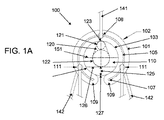
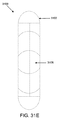
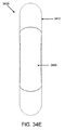
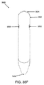
図1Aから1Cを参照すると、一実施形態では、整形外科用関節デバイス100は、1つ以上の内側膜またはシート構造110を有する弾力性または可撓性非線状外体102を備える。外体102の非線状形状は、2つの自由ループ端109を有する開ループ弓状構成(例えば、「C」字形)を備えてもよいが、他の実施形態では、外体は、楕円形または多角形を含むがそれに限定されない他の形状を含んでもよく、開構成および閉構成の両方を含んでもよい。種々の開放構成の整形外科用デバイスの実施例は、2008年9月12日出願の米国特許出願第12/210,101号、名称「Suture−Based Orthopedic Joint Devices」でさらに詳細に説明されており、参照によりその全体が本明細書に組み込まれる。いくつかの変形例では、開ループ構成は、関節運動部に印加される負荷力、剪断力、および/もしくは圧縮力、ならびに/または関節の負荷を分配することによって、より大きい可撓性を与えてもよく、変形に対する抵抗を低減してもよい。しかしながら、いくつかの実施形態では、閉構成を有する整形外科用デバイスが用いられてもよい。
With reference to FIGS. 1A-1C, in one embodiment, the orthopedic
整形外科用デバイス100の外体102は、図1Bで示されるように、円形の断面外形を有する。しかしながら、他の実施形態では、正方形、楕円計、三角形、または任意の他の形状を含むがそれらに限定されない、種々の断面外形のうちのいずれかを有してもよい。整形外科用デバイス100の外体102は、取外し可能内部支持またはコア要素105をさらに備えてもよい。図1Aで示される実施形態では、コア要素105はまた、開ループ弓状構成も備える。他の実施形態では、コア要素は、外体102と同一または同様の構成を含んでも含まなくてもよい。例えば、取外し可能内側コアは、複数のセグメントとして外体に埋め込まれてもよい。取外し可能コア105は、外体102の外面101と内面103との間のどこかに、またはその上面もしくは下面に、または外体102の表面上に、部分的もしくは完全に位置してもよい。いくつかの実施形態では、整形外科用デバイス100は、適所にコア105を伴って関節に最初に埋め込まれてもよいが、コア105は、後で除去されてもよい。場合によっては、関節構造または層におけるコア105の一時的な使用は、整形外科用デバイス100の埋め込みを容易にしてもよい一方で、コアの除去は、使用中に整形外科用デバイス100の浮動特性および/または可撓性を増進してもよい。整形外科用関節デバイスにおける取外し可能コアの種々の実施形態は、2009年4月21日出願の米国特許出願第61/171,408号、名称「Orthopedic Joint Device with Removable Core」でさらに詳細に説明されており、参照によりその全体が本明細書に組み込まれる。図1Aで図示されるように、コア105は、1つ以上の拡大端または球状端107を有してもよい。コア構成要素105の拡大端107は、端105が外体102を貫通、またはそこから突出し得る危険性を低減してもよい。いくつかの実施形態では、コア要素105は、ニッケル−チタン等の形状記憶材料から作製されてもよい。いくつかの実施形態では、コア要素は、放射線不透過性であってもよい。
The
整形外科用デバイス100の外体102は、テザーの取り付けのために構成される1つ以上の開口部を備えてもよい。図1Aでは、整形外科用デバイス100を関節腔に引き込むか、または別様にそれに送達するために、送達テザー141が使用される。送達テザー141は、外体102上に位置する開口部または穴108を使用して、デバイス100に取り付けられてもよい。開口部108は、外体102の2つの端109の中間に位置してもよいが、他の実施形態では、開口部108は、外体102に沿うどこかにあってもよい。整形外科用デバイス100は、デバイス100の送達または操作をさらに容易にするために、随意に、付加的な開口部111をさらに備えてもよい。付加的なテザー142は、ループ端109により近い場所に、取外し可能に取り付けられてもよい。いくつかの実施形態では、デバイス100の除去を容易にするために、付加的なテザーが使用されてもよい。図1Aで描写されるように、テザー141および142は、外体102のコア要素105と内面103との間に位置してもよい。テザー141および142が開口部108および111を通過するときにコア要素105を包み込むことによって、コア要素105への力を再配分することで、デバイス100の外体102への損傷が低減され得る。他の変形例では、テザー開口部は、外体102の外面101または内面103のいずれかのより近くに、コア要素105からオフセットされてもよい。外体の開口部に加えて、他の好適な機構によって縫合糸が外体102に連結されてもよい。縫合糸連結機構の種々の実施例は、以前に参照により組み込まれた、2008年9月12日出願の米国特許出願第12/210,101号、名称「Suture−Based Orthopedic Joint Devices」でさらに詳細に説明されている。
The
他の実施形態では、整形外科用デバイス100の外体102は、例えば、金属または非金属、ポリマーまたは非ポリマー、生体再吸収性または非生体再吸収性、透過性または半透過性、脂溶性、親水性、または疎水性であってもよい、種々の剛性、半剛性、可撓性、ゲル、または液体材料のうちのいずれかを含んでもよい。これらの材料としては、ステンレス鋼、コバルトクロム、チタン等を含むが、それらに限定されない。いくつかの実施形態では、整形外科用デバイス100の外体102は、Nitinol、または形状記憶プラスチック等の形状記憶材料、ポリカーボネートウレタン等のポリマーまたは合成材料、熱分解炭素、種々のセラミックまたはヒドロキシアパタイトベースの材料のうちのいずれか、PTFE、シリコーン、ナイロン、ポリエチレン、ポリプロピレン、ポリカーボネート、ポリイミド、ポリカーボネート、ポリウレタン、ポリウレタン炭酸塩、PEEK、PEKK、およびPEBAX等のポリマー、PGA、PLA、PLGA、PDS、および同等物等の種々の生体再吸収性材料のうちのいずれか、ならびにキトサン、コラーゲン、蝋およびアルギン酸塩ベースの材料、小腸粘膜下組織(SIS)等の動物由来の材料、および前述したものの組み合わせを含む。いくつかの実施形態では、1つ以上の治療薬は、整形外科用デバイス100の表面上に被覆されてもよく、または薬剤送達のための1つ以上の貯留部、貯蔵物、空洞、ウエル、ポケット、多孔質材料、気泡またはカプセルに埋め込まれてもよい。整形外科用関節デバイスと併せて使用されてもよい治療薬、および関連する薬物放出機構の種々の実施例は、以前に参照により組み込まれた、2008年9月12日出願の米国特許出願第12/210,101号、名称「Suture−Based Orthopedic Joint Devices」でさらに詳細に説明されている。
In other embodiments, the
コア要素105は、前述の材料のうちのいずれかを含んでもよく、外体102と同じまたは異なる組成を有してもよい。いくつかの変形例では、コア要素105は、形状記憶材料を含む。形状記憶材料は、Nitinol、または形状記憶プラスチック、ポリマー、合成材料等の、熱設定/成形形状記憶材料から作られてもよい。一実施形態では、コア要素105は、シリコーンまたはポリカーボネートウレタンを含む、外体102または外側ブランケットによって封入されるNitinol等の、金属「開」リングを備える。一実施形態では、コア要素105は、硬化ポリマーを含む一方で、他の実施形態では、コア材料は、放射線不透過性であってもなくてもよいゲルまたは液体を外体102の空洞内に含んでもよい。一実施形態では、コア要素105は、ポリマーおよび放射線不透過性材料を含む。一実施形態では、コア要素105は、開リング構成、馬蹄形構成、またはらせん構成等の弓状構成を有する熱設定Nitinolが、冷却または塑性変形を通して送達のために直線状になり、次いで、適切にサイズ決定された皮下注射針を使用する一実施形態等の送達システムからいったん解放されると、その元の熱設定形状に回復することができるように、構成される。一実施形態では、コア要素105は、屈曲または変形させることができる非形状記憶材料を含む。一実施形態では、コア要素105は、編組みされた、織られた、または接合された上記に列記した材料のうちの1つ以上を含む、複数の構造を備える。さらに他の実施形態では、コア要素105は、ビード、棒、リング、立方体等の複数の無接続構造を備えてもよい。
The
内側シート構造または膜110は、外体102の内側領域104の少なくとも一部分に架かってもよく、デバイス100の拡張を制限するために、および/または外体102の2つの端109の移動を拘束するために使用されてもよい。これらの構造的特徴および他の構造的特徴は、送達構成の過剰なゆがみを制限しながら、低減された送達外形を促進してもよい。内側膜は、埋め込まれたデバイスのための付加的な関節形成表面を提供してもよい。膜110は、概して、平坦または平面構成を有してもよいが、他の実施例では、膜110は、外体102の増大した伸展を可能にし得る、その自然な構成における余剰な材料を有してもよい。低減された厚さは、均一であってもよく、または不均一であってもよい。いくつかの実施例では、厚さは、膜110の外側領域から中心領域まで、または端109から膜110の正中線まで減少または増大してもよい。図1Bで示される実施形態では、内側膜110は、略均一厚さ112であり、整形外科用デバイス100の上面106と下面108との間の中間に位置する、略平面の構成である。他の実施形態では、膜110は、膜110の1つ以上の表面に沿って1つ以上のくぼみまたは溝を含む、可変厚さを有してもよい。平面構成に加えて、膜110は、例えば、波形、凹面、凸面、またはテーパ状領域を含む、非平面構成を有する1つ以上の領域を有してもよい。いくつかの実施形態では、内側膜110は、整形外科用デバイス100の上面106または下面108のいずれかにより近い位置に位置してもよい。いくつかの変形例では、膜110の平均的な場所または膜110の領域の場所は、デバイスの下面108から上面106までの距離の割合として特徴付けられてもよく、約0%から100%までのどこかであってもよく、あるときには約0%、5%、10%、15%、20%、25%、30%、35%、40%、45%、50%、55%、60%、65%、70%、75%、80%、85%、90%、95%、または100%であってもよい。いくつかのさらなる変形例では、膜は、例えば凸面/凹面/波形構成といった、非平面構成を有してもよく、下面108および/または上面106を超えて突出してもよく、例えば、負の割合または約100%よりも大きい割合のいずれかとして表されてもよい。内側膜110の厚さ112は、図1Bで示されるように、外体102の厚さ未満であってもよく、または外体102の厚さとほぼ同じであってもよい。膜110は、射出成形または圧縮成形等の一般的な製造技術を使用して、外体102と一体的に形成されてもよい。膜110はまた、直接的に、またはワイヤ、支柱、もしくはメッシュ等の補強構造とともに外体102に取り付けられるか、または組み込まれてもよい。内側膜110は、それが外体102と接触するその周囲全体に沿って、外体102に連結されてもよい。いくつかの実施形態では、膜110は、膜の周囲の遠位部分に沿ってのみ外体102に連結され、したがって、外体102の端109の可動性を増強してもよい。いくつかの実施形態では、端109の間の距離は、約0.1mm乃至約5mm、あるときには約0.5乃至約3mm、他のときには約1乃至約3mmである。いくつかの実施形態では、内側膜110は、外体102と同じ材料を含む。いくつかの実施形態では、内側膜110は、外体102とは異なる材料を含む。いくつかの実施形態では、外体102と同じ材料を含む内側膜110の割合(重量または容量での)は、例えば、5%、10%、15%、20%、25%、30%、35%、40%、45%、50%、55%、60%、65%、70%、75%、80%、85%、90%、または95%であってもよい。例えば、内側膜110は、外体102と同様の材料を含んでもよいが、均一または非均一のサイズまたは長さであるポリマーまたは金属ストランドをさらに備え、例えば織物またはスクリーン構成といった、ランダムな、またはランダムな編成および配向を有する。この付加的な内側膜構造は、内側膜110に対して内部、外部、または両方であってもよく、単一の層または複数の層を備えてもよい。
The inner sheet structure or
内側膜110は、整形外科用デバイス100の中心軸または送達軸に対して中心に位置する、開口部120をさらに備えてもよい。いくつかの変形例では、開口部を有する内側膜は、デバイス100の送達外形のより大きい低減を可能にする一方で、膜110の面外の変位も低減し得る、より大きい変形または折り畳みを提供してもよい。以下でさらに詳細に論議されるように、開口部120を有する内側膜110はまた、変形した端109が、低減した抵抗または低減したゆがみを伴って、関節腔に進入するための遷移表面を提供してもよい。
The
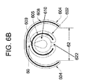
開口部は、種々の形状のうちのいずれかを有してもよいが、描写された実施例では、開口部は、狭い端および広い端を有する略涙形を備える。いくつかのさらなる実施例では、端は、円121および122、またはその部分として特徴付けられてもよい、略弓状の形状を有してもよい。しかしながら、他の実施例では、開口部の周囲は、非弓状であってもよく、または、例えば任意の端を欠いた、細長くない構成を備えてもよい。より小さい直径121’を有する遠位円121およびより大きい直径122’を有する近位円122は、両方の円がデバイス100の中心軸に沿って整合された状態で相互に外接してもよい。遠位円121は、外体102(または膜110の外周)の内側境界線104に接触してもよく、または外体102の内側境界線104から中心にオフセットされてもよい。遠位円121はまた、その最遠位点123が外体102の長さに沿って位置するようにさらに構成または配向されてもよい。近位円122の中心は、開口部120の最近位点126(例えば、この特定の実施形態では、近位円122の最近位点)と、内側膜110の最近位点127との間の距離125を伴って、膜110の中心と整合されてもよい。いくつかの実施形態では、近位円122の最近位点126と内側膜110の最近位点127との間の距離125は、約0.1mm乃至約5mm以上、あるときには約0.5mm乃至約3mm、他のときには約1mm乃至約2mmである。
The opening may have any of a variety of shapes, but in the depicted example, the opening comprises a generally tear shape having a narrow end and a wide end. In some further examples, the ends may have a generally arcuate shape that may be characterized as
他の変形例では、開口部の外側縁は、近位円および遠位円の周囲を接続する接線を備えなくてもよい。円は、デバイスの中心軸に沿って、または一方または両方の円がデバイスの中心軸の一方に対してオフセットされた状態で、重複してもよく、または離間されてもよい。他の変形例では、遠位円の直径は、近位円の直径とほぼ同じであり、それにより、丸い端を有する長方形の開口部を形成してもよい。さらに他の変形例では、遠位円の直径は、近位円の直径よりも大きくてもよい。さらに他の実施形態では、近位円は、外体の内側円と同心円状でなくてもよい。近位円の中心点は、整形外科用デバイスの横中心線の上側または下側のいずれかに位置してもよい。全てのこれらのパラメータ(例えば、互いに対する、および/または外体の内側領域に対する、2つの円の相対的な位置、2つの円の相対的なサイズ等)は、異なる構成を有する開口部を形成するために、独立して変動してもよい。開口部の代替の構成の例は、円形、三角形、丸い長方形、台形、楕円形、逆涙滴形(例えば、逆にした円の位置)、および図8の形状を含むが、それらに限定されない。いくつかの実施例では、開口部は、規則的または不規則的な曲線または多角形の形状を有してもよい。 In other variations, the outer edge of the opening may not comprise a tangent connecting the perimeter of the proximal and distal circles. The circles may overlap or be spaced along the central axis of the device or with one or both circles offset relative to one of the central axes of the device. In other variations, the diameter of the distal circle may be approximately the same as the diameter of the proximal circle, thereby forming a rectangular opening with a rounded end. In still other variations, the diameter of the distal circle may be larger than the diameter of the proximal circle. In still other embodiments, the proximal circle may not be concentric with the inner circle of the outer body. The center point of the proximal circle may be located either above or below the transverse centerline of the orthopedic device. All these parameters (eg, the relative position of the two circles relative to each other and / or relative to the inner region of the outer body, the relative size of the two circles, etc.) form an opening having a different configuration May vary independently. Examples of alternative configurations of the opening include, but are not limited to, a circle, triangle, round rectangle, trapezoid, ellipse, reverse teardrop (eg, inverted circle position), and the shape of FIG. . In some embodiments, the opening may have a regular or irregular curved or polygonal shape.
いくつかの実施形態では、近位円122の直径122’に対する遠位円121の直径121’の比率は、約1:5、あるときには約1:3、あるときには約1:1、他のときには約2:1であってもよい。いくつかの実施形態では、2つの円の中心点の間の中心間距離は、約0.01mm乃至約10mm、あるときには約0.1mm乃至約5mm、他のときには約1mm乃至約3mmである。
In some embodiments, the ratio of the
整形外科用デバイス100が、送達テザー141によって引き込まれて、および/または別様に関節切開部を通して関節の中に挿入されたとき、肩領域150(例えば、図1Cで最適に描写されるように、デバイス100が最初に関節切開部に進入するときの、デバイス100の先頭縁)は、遠位円121によって占有される開口部120の部分を変形させ始めるか、または圧縮し始めてもよい。整形外科用デバイスが1つ以上の中心開口部を備えていないいくつかの実施形態では、内側膜は、整形外科用デバイス100が送達テザー141によって引き込まれるときに折り畳んでもよい。デバイス100が関節の中にさらに引き込まれるにつれて、圧縮力は、弓状外体102に沿って2つの端部109に向かって平行移動し、2つの端を内向きかつ垂直に変形させる。結果として、デバイス100の2つの端109は、図1Cで図示されるように、デバイス100の平面から移動して相互に交差して、アルファ形を形成してもよい。デバイス100が関節腔の中にさらに送達されるにつれて、外体102から内側膜110に平行移動した圧縮力、および/または2つの端109の交差は、内側膜を変形および/または折り畳ませてもよい。いくつかの実施例では、内側膜110の近位部分152は、膨らんで遠位に折り重なってもよく、整形外科用デバイス100の交差した2つの端部109が殆ど抵抗を伴わずに関節切開部に進入するための、楔状の遷移表面を形成する。折り畳みは、近位円122に近接する線に沿って起こってもよい。他の実施形態では、折り畳みは、2つの円の中心軸に沿う任意の点で起こってもよい(例えば、遠位円121の最遠位点128と、近位円122の最近位点126との間の任意の点)。
Should
いったん整形外科用デバイス100が関節腔の中に引きこまれて、交差したループ端109が関節の切開部を通過すると、デバイス100は、交差せずに略同じ面内に置かれる2つのループ端109を有する元のまたは基礎の開ループ弓状構成であってもよい、その基礎構成または事前展開構成に向かって復帰または拡張してもよい。他の実施例では、解剖学的および/または機械的拘束は、無拘束の状態へ戻るデバイス100の復帰を制限してもよい。いくつかの実施形態では、デバイス100の初期の挿入後の再配置および/または2つの端部109の挿入後の位置の調整を容易にして、デバイスがその元の構成に復帰するのに役立つように、付加的なテザー142が使用されてもよい。
Once the
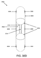
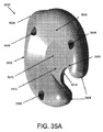
図2Aは、開ループ弓状構成を有する外体202と、涙滴形開口部220を有する内側膜210とを備える、整形外科用関節デバイス200の別の実施形態を描写する。デバイス200は、骨−骨接触の間隔を低減した密着した関節への挿入またはアクセスを容易にするように構成される、テーパ状または楔形の挿入構造230をさらに備える。テーパ状挿入構成を有する整形外科用デバイスは、デバイスが関節腔を通して引き込まれるにつれて徐々に分離し、それにより、関節切開部を通しての整形外科用デバイスの進入を促進してもよい。テーパ状または楔要素はまた、外体の外周で、付加的な関節形成要素または表面を提供してもよい。他の変形例では、外周関節形成要素は、テーパ状または楔構成を有する必要がある。
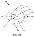
FIG. 2A depicts another embodiment of an orthopedic
テーパ状挿入構造は、外体202の遠位領域に沿う、かつ外体202の外側湾曲201の遠位半体の一部分または全体に架かる、単一の要素を備えてもよい。挿入構造230は、略同じ平面上にあってもなくてもよく、その長さに沿って均一または不均一な断面形状またはサイズを有してもよい。挿入構造230を備える材料は、外体202の材料と同じであっても異なっていてもよい。他の実施例では、テーパ状挿入構造230は、区分化されてもよく、または複数の挿入構造(例えば、図2Aの挿入要素231から233)を備えてもよい。区分化された、または複数の挿入構造は、例えば断面形状、長さ、材料、またはデュロメータといった構造的特性を含むが、それらに限定されない、類似したまたは異なるテーパ状構成をそれぞれが有する、複数の挿入要素を備えてもよい。さらに、複数の挿入構造は、独立した曲げまたは変形を可能にすることによって、デバイスの全体的な可撓性を増進し得る。隣接する挿入要素は、1つ以上の間隙によって分離されてもよい。間隙は、外体102の長さ、テーパ状挿入構造230の全長、または単一の挿入要素231、232、もしくは233の長さに対する、絶対長さまたは相対長さとして描写されてもよい。間隙はまた、挿入要素を垂直に分離してもよく、例えば、1つ以上の挿入要素が、外体の上面および下面に対して異なる高さで位置してもよい。いくつかの実施例では、隣接する挿入要素は、重複長さを有してもよいが、それらの相対的な高さまたは垂直位置に関して離間または分離される。
The tapered insertion structure may comprise a single element along the distal region of the
図2Aの実施形態は、中心挿入要素231と、2つの肩挿入要素232および233とを備える。他の変形例では、要素は、より多いまたはより少ない数(例えば、1つ、2つ、4つ、5つ、またはそれ以上)であってもよい。挿入要素は、外体に対して、対称的または非対称的に位置してもよい。図2Bで図示されるように、中心挿入要素231は、外体202からその遠位縁236へのテーパ状構成を有してもよい。いくつかの実施形態では、テーパ状長さは、挿入要素231の遠位縁236と、外体と接触するテーパ状表面間の中間点との間の距離として特徴付けられてもよい。図2Bで図示されるように、挿入要素231の上面238および下面239は、外体102の最上面241および最下面242からテーパ状になるが、他の変形例では、その間の任意の場所からテーパ状になってもよい。テーパ状表面の相対テーパ状角度237は、挿入要素231の遠位縁236の遠位接線(または挿入要素の遠位縁と交差し、かつ外体の重心に垂直な他の線)と、挿入要素231のテーパ状上面238または下面239との間の角度によって特徴付けられてもよい。各表面のテーパ状角度は、同じであっても異なっていてもよく、約1度乃至約90度、あるときには約25度乃至約85度、他のときには約45度乃至約80度の範囲内のいずれかであってもよい。挿入要素のテーパ状外形は、デバイス200の中央平面に対して中心に置かれても置かれなくてもよい。挿入要素231の遠位縁236の垂直位置は、デバイス200の上面241から下面242までの、または上面241から下面242の上側もしくは下側のどこかに位置してもよい。図2Cは、デバイスの変形例を描写し、デバイス200の下面239は、図2Cで図示される通りである。挿入要素は、図2Bおよび2Cで図示されるように、線状テーパ状外形を有しても有しなくてもよい。例えば、挿入要素231の上面238は、曲線または起伏構成を備えてもよい。実施例について、示された実施形態の中心挿入要素231は、丸い長方形状を有するが、他の実施形態では、円弧形状を有するように陥凹肩を有してもよい。
The embodiment of FIG. 2A comprises a
肩挿入要素232および233は、中心挿入要素231と同じ形状および/またはテーパ状外形を有しても有しなくてもよい。挿入要素(例えば、区分の形状または材料、テーパ状外形)の種々の側面は、挿入要素の種々の実施形態を形成するように、独立して改変されてもよい。そのような可撓性は、各挿入要素が独立して設計されることを可能にする。例えば、いくつかの用途では、肩挿入要素は、関節腔を鳴らす外周結合組織を切断するようにデバイスの能力を高めるために、中心挿入要素よりも小さいテーパ状角度を備えてもよい。
Shoulder insert
いくつかの実施形態では、挿入要素は、関節腔への非外傷性の進入を促進してもよい、滑らかな、または鈍的な遠位縁を備えてもよい。他の実施形態では、挿入要素のうちのいくつかまたは全ては、組織を切り開くように構成される、ブレード状の縁を備えてもよい。挿入要素は、整形外科用デバイスの外体と同じ材料から作製されてもされなくてもよく、外体材料よりも高い、または低いデュロメータを有してもよい。いくつかの実施形態では、挿入要素は、区分が可変剛性を備え得るように、1つを超える材料で作製されてもよい。 In some embodiments, the insertion element may comprise a smooth or blunt distal edge that may facilitate atraumatic entry into the joint space. In other embodiments, some or all of the insertion elements may comprise a blade-like edge that is configured to cut through tissue. The insertion element may or may not be made of the same material as the outer body of the orthopedic device and may have a durometer that is higher or lower than the outer body material. In some embodiments, the insertion element may be made of more than one material so that the section can have variable stiffness.
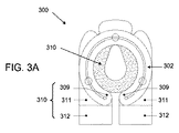
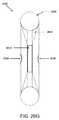
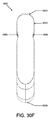
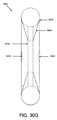
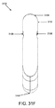
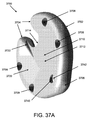
いくつかの実施形態では、整形外科用関節デバイスは、その開ループ端の周囲に位置する近位羽またはタブをさらに備えてもよい。羽またはタブは、埋め込み中のデバイスの操作および/または配向の維持を促進してもよい。図3Aでは、整形外科用デバイス300は、外体302から近位に延在する、近位羽310を備える。羽310は、2つの帯域311および312を備えてもよい。各帯域のテーパ状外形は、同じであっても異なっていてもよい。例えば、遠位帯域311は、整形外科用デバイス300の外体302とほぼ同じ厚さを備えるが、羽310の近位帯域312は、遠位帯域311とのその交差点からその近位端に向かってテーパ状になるテーパ状構成を備えてもよい。羽310は、外体302と一体的に形成されてもよく、または挿入要素がデバイス本体302に取り付けられるのと同様の方法で、外体302に取り付けまたは埋め込まれてもよい。いくつかの実施形態では、外体302の端309の近位にある羽310の長さは、約0mm乃至約10mm、あるときには約1mm乃至約5mm、他のときには約2mm乃至約4mmの範囲内であってもよい。図3Aの羽310は、外体302の最外領域を超えて外側に延在しないが、他の変形例では、延在してもしなくてもよい。
In some embodiments, the orthopedic joint device may further comprise a proximal wing or tab located around its open loop end. The wings or tabs may facilitate the manipulation and / or maintenance of orientation of the device during implantation. In FIG. 3A, the
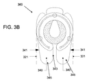
図3Bは、テーパ状外側縁341と、丸い近位縁345と、直線の内側縁343とを備える近位タブまたは羽340を有する、整形外科用デバイス360の変形例を例示する。他の変形例では、例えば、外側縁は、直線であっても広がっていてもよく、内側縁は、テーパ状でも広がっていてもよい一方で、近位縁は、四角であっても鋭いテーパ状であってもよい。図3Cは、丸い角353を有する遠位羽350を有するが、外体302の外側または近位外形を超えて延在しない、整形外科用デバイス375の別の変形例を描写する。羽350の外側縁351は、互いに、またはデバイス375の中心軸に略平行な構成を備えるが、テーパ状または広がった外形を有してもよく、また、互いに異なる外形を有してもよい。他の変形例では、図3Aから3Cで図示されるデバイスの先頭縁上の挿入要素は、省略されてもよいが、それらの特定の羽要素は保持する。
FIG. 3B illustrates a variation of the
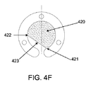
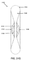
いくつかの実施形態では、整形外科用関節デバイスは、それぞれがデバイスの外体の内側領域の少なくとも一部分に架かる2つ以上の重複小葉を備える、関節面を備えてもよい。重複小葉は、付加的な関節面を提供しながら、外体の自由ループ端の移動を制限するように構成されてもよい。図4Aおよび4Bは、それぞれが外体402によって縁取られる領域404の約半分に架かる2つの重複小葉410および420を備える、整形外科用関節デバイス400の一実施形態を描写する。2つの小葉410、420は、デバイス400の中央平面431に対して対称的に配置されてもされなくてもよい。いくつかの実施形態では、小葉410、420は、どちらも中央平面431の上側に位置するが、他の実施形態では、どちらも、デバイス400の中央平面431の下側に位置してもよい。いくつかの実施形態では、小葉410と412との間の垂直距離は、約0.1mm乃至約5mm、あるときには約0.5mm乃至約3mm、他のときには約1mm乃至約2mmであってもよい。いくつかの実施形態では、整形外科用デバイスは、2つを超える小葉を備えてもよい。小葉410は、近位基点411と遠位頂点412との間で外体402に取り付けてもよい。基点411と頂点412との間の小葉縁413は、図4Cおよび図4Dで図示されるように、それぞれ、外体402の内側領域406の中心点405と交差してもしなくてもよい。図4Eおよび4Fで図示されるように、いくつかの変形例では、小葉410および420の頂点412および422は、それぞれ、デバイス402の内側領域406の中心点405に、またはその近位に位置してもよい。これらの実施例では、小葉410、412は、比較的により大きい拘束力を、デバイス400の端408、409上に、ならびにより大きい関節面に提供してもよい。いくつかの実施例では、小葉縁413、423とデバイス400の中心軸との間の角度は、約0度乃至約90度、あるときには約20度乃至約70度、他のときには約40度乃至約60度の範囲内であってもよい。小葉縁は、残りの小葉と同じまたは異なる厚さを有してもよく、いくつかの実施例では、ワイヤ、コード、または他の要素で補強されてもよい。2つの小葉410および420は、同じ材料を含んでもよく、または異なる材料を含んでもよい。また、小葉410および420は、同じ厚さを有してもよく、または異なる厚さを有してもよい。
In some embodiments, the orthopedic joint device may comprise an articulating surface, each comprising two or more overlapping leaflets that span at least a portion of the inner region of the outer body of the device. The overlapping leaflets may be configured to limit movement of the free loop end of the outer body while providing additional articulating surfaces. FIGS. 4A and 4B depict one embodiment of an orthopedic
図4Aから4Dを再び参照すると、デバイス400が関節腔の中に挿入され、外体402の外側領域がデバイス400の中心軸に向かって拘束されるとき、小葉410および420の可撓性は、2つの端408および409の内向きまたは重複移動を可能にしてもよい。2つの端408および409が交差した所で、小葉410および420を、端408および409の面外の移動によって上昇させて、それにより、2つの交差した端408および409の挿入を容易にするために、楔形の、または傾斜した遷移表面を提供してもよい。
Referring back to FIGS. 4A through 4D, when the
いくつかの変形例では、小葉410と420との間の空間または潜在的な空間は、薬剤放出構造または1つ以上の生分解性材料を含有してもよい。小葉410および420は、その中で物質の放出および/または分解を制御する、多孔質材料または他の速度制御層を備えてもよい。いくつかのさらなる変形例では、重複小葉の1つ以上の部分は、液体、懸濁液、または他の材料の保持を容易にするために、密閉されていてもよく、または一体的に形成されてもよい。1つの具体的実施例では、膜は、それ自体の上に折り畳まれて、その露出縁に沿って外体102の内側境界線104に密閉される層構造を備えてもよい。折り畳み層構造間の空間へのアクセスを容易にする一方で、弁を通しての任意の物質の流出に抵抗するように、弁要素が提供されてもよい。
In some variations, the space or potential space between
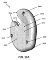
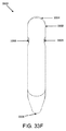
図5Aは、弓状または三日月状のスリットまたは縁504を有する内側膜502と、支持帯域510の間に位置するより小さい断面積を備える複数の関節運動帯域508をさら備える区分化外体506とを備える、整形外科用関節デバイス500の別の実施形態を描写する。スリット504は、膜502を遠位膜区間512および近位膜区間514に分離する。外体506は、端516および518と、随意的なコア520と、送達開口部522とをさらに備えてもよい。図5Bは、整形外科用関節デバイス530の別の実施形態を図示し、区分化外体532は、より多い数の関節運動帯域534、536、538を備える。前述のように、デバイス500の関節運動帯域508について、デバイス530の関節運動帯域534、536、538は、外体506のより大きい屈折を促進してもよく、デバイス530の送達外形をさらに低減してもよい、低減した直径または断面積の領域を備えてもよい。いくつかの実施形態では、関節運動帯域534、536、538の軸方向断面積は、残りの外体502の軸方向断面積の、約1%乃至約99%、あるときには約25%乃至約90%、他のときには約50%乃至約80%の範囲内であってもよい。関節運動帯域は、非関節運動帯域と同じ材料から作製されてもされなくてもよい。いくつかの実施形態では、関節運動帯域は、さらに大きい可撓性または変形性を提供するために、非関節運動帯域よりも弾力性のある材料から作製されてもよい。描写された関節運動帯域534、536、538は、外体506およびコア要素520に対して略対称的に位置するが、他の実施例では、1つ以上の関節運動帯域は、オフセットされた位置を有してもよい。各関節運動帯域は、同じまたは異なる構成(例えば、材料、長さ、軸方向断面積)を有してもよい。
FIG. 5A illustrates a segmented
図5Bおよび5Cは、関節運動帯域534、536、538と、内側膜502とを備える整形外科用デバイスの送達中の1つの例示的な変形を図示する。デバイス530が関節の切開部を通して引き込まれるときには、デバイス530が送達開口部522に対して引き込まれるか、または挿入されるにつれて、デバイス530の遠位端540が最初に関節切開部に進入する。遠位端540に及ぼされる圧縮力は、関節運動帯域534、536、538を通して円周方向に変換してもよく、デバイス530の端516、518を交差させて、アルファ形を形成させる。デバイス530の送達中に、弓状または部分円形構成を有する近位膜512も圧縮されてもよい。図5Cで図示されるように、近位膜512は、テーパ状構成を呈するその近位縁504とともに上方に圧縮されて折り畳まれてもよく、デバイス530の交差した端516、518の関節腔の中へのさらなる挿入を容易にしてもよい。図5Aおよび5Bで示される実施形態では、デバイスの送達中のデバイスの可撓性を高めるために、弓状形状の開口部を備える内側膜を有する関節運動帯域が使用されるが、他の形状(例えば、前述の涙滴形状)の開口部を有する膜、または複数の小葉から成る膜が使用されてもよい。
FIGS. 5B and 5C illustrate one exemplary variation during delivery of an orthopedic device comprising
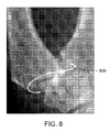
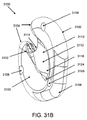
いくつかの先の実施例で描写されるように、埋め込まれた整形外科用デバイスは、関節包の形状、および/または関節の関節運動表面の相対的な場所および状態に依存して、面外で変形してもよい。図8では、例えば、手の手根中手関節の中に挿入されるC字形の整形外科用デバイス800は、コルクスクリューまたはらせん形構成に変形してもよい。いくつかの実施例では、面外構成は、関節腔の骨の突出物の受動的係合を伴ってもよく、いくつかのさらなる実施例では、骨および/または軟組織の貫通を必要とせずに、デバイスの固着または配向を促進してもよい。いくつかの実施例では、デバイスを、骨および/または組織を包囲する組織と確実に係合するように、機械的特徴が整形外科用関節デバイスの1つ以上の外面に加えられてもよい。そのような機械的特徴は、隆線、溝、ベルクロフック、1つ以上の接着剤、または整形外科用デバイスの表面を、包囲する骨および/または組織に噛合させる任意の同等の機構等の、微小表面特徴を含んでもよい。
As depicted in some previous examples, an implanted orthopedic device may be out-of-plane depending on the shape of the joint capsule and / or the relative location and condition of the articulating surface of the joint. It may be deformed with. In FIG. 8, for example, a C-shaped
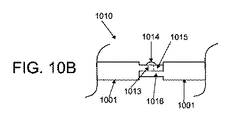
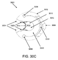
いくつかの変形例では、整形外科用デバイスは、使用中に、関節腔の1つ以上の構造に受動的に巻き付く、または別様にそれに係合するように構成される、受動的固着要素を備えてもよい。図6Aでは、例えば、整形外科用デバイス600は、外体602およびコア605がどちらもリングまたはC字形構成である、超弾力性コア605(例えば、ニッケル−チタン合金)を有する外体602を備える。いくつかの実施形態では、コア605は、放射線不透過性であってもよい。デバイス600はまた、内側膜610と、膜開口部620とを備えてもよい。デバイスは、連結部位またはブリッジ606において外体602のより大きい表面618に取り付けられる、固着体604をさらに備える。いくつかの変形例では、複数のブリッジが外体と内体との間に提供されてもよい。いくつかのさらなる実施例では、付加的な固着体が提供されてもよく、同一または異なる構造で、内体または外体に取り付けられてもよい。外体604は、超弾力性コア608を備えてもよい。コア605および608は、ブリッジ606を通して相互接続コアを使用して接続されてもされなくてもよく、同じ構成(例えば、断面サイズ、形状、および材料)を備えても備えなくてもよい。図6Aでは、コア605および608は、コアによって相互接続されず、ブリッジ606において付加的な可撓性を提供してもしなくてもよい。内体602、外体604、およびブリッジ606は、同じ構成(例えば、断面サイズ、形状、および材料)を備えても備えなくてもよい。この実施例では、超弾力性コア605および608は、どちらもニッケル−チタン合金を含み、外体602および固着本体606は、どちらもポリカーボネートウレタンを含むが、固着体606は、外体602と比較して低減した断面積を有し、固着体604により大きい可撓性を提供してもよい。この実施例では、内体602および固着体604はまた、それぞれ、それらの端614と616との間に位置する、間隙622および624も備える。
In some variations, the orthopedic device is configured to passively wrap around or otherwise engage one or more structures of the joint cavity during use. May be provided. In FIG. 6A, for example, the
図6Bは、関節腔における構造の係合を容易にしてもよく、その結果、外体602の固着および設置を容易にしてもよい、外体604の端616間の間隙622が広げられた、または別様に分離された、展開された構成のデバイス600を描写する。外体602の端614間の間隙622は、膜110によって制限される分離を伴って、ほぼ同じままであってもよい。
FIG. 6B may facilitate engagement of the structure in the joint cavity, resulting in a
外体および固着体は、その展開された構成または自然の構成にあるときに、同じ平面の中にあってもなくてもよい。図6Cは、外体602と、固着体604の相対的な面外の配向とを描写する、図6Aおよび6Bのデバイス600の側面図である。外体と固着体との間の相対角度630は、約0度乃至約180度、あるときには約0度乃至約45度、他のときには約10度乃至約25度の範囲内であってもよい。
The outer body and the anchoring body may or may not be in the same plane when in their deployed or natural configuration. 6C is a side view of the
開口部を有する内側膜、遠位貫通区間、近位羽、および/または関節運動帯域等の、整形外科用関節デバイスの種々の特徴が、この明細書の全体を通して論議されていることに留意されたい。任意の実施形態では、それらは、個々に存在してもよく、または外体の構成、外体の材料、および/または外体に対する縫合糸取り付け機構等の、デバイスの他の側面の組み合わせのうちのいずれかを有する任意の組み合わせであってもよい。 It is noted that various features of the orthopedic joint device are discussed throughout this specification, such as an inner membrane with an opening, a distal penetrating section, a proximal wing, and / or an articulation zone. I want. In any embodiment, they may be present individually or out of a combination of other aspects of the device, such as outer body configuration, outer body material, and / or suture attachment mechanism to the outer body Any combination having any of the above may be used.
図6Aで描写されるように、デバイス600はまた、デバイスの操作および送達を容易にするために、1つ以上のテザー開口部632、634、および636を外体602および/または固着体604上に備えてもよい。図6Dおよび6Eは、図6Aから6Cのデバイスを有するテザー640および642の使用の一実施例を描写する。第1のテザー640は、デバイス600の送達軸に沿って外体602の中に位置するテザー開口部632に取外し可能に連結されてもよい。外側テザー642は、外側テザー開口部634および636の両方に摺動可能に連結され、1つのテザー642は、開口部634および636の各外側の組に連結される。2つの外側テザー642の使用は、デバイス600の異なる領域の別々の操作を可能にしてもよい。外側のテザー624に張力をかけることで、デバイス600の送達外形のさらなる低減を促進してもよい。デバイス600を関節腔の中に設置した時点で、固着体604を拘束された状態から解放して固着体端616の変位または分離を可能にするように、外側テザー642がデバイス600から分離されてもよい。図7は、手首の大菱形骨654とともに関節運動する中手の近位端652の周辺のデバイス600の固着体604の受動的係合を概略的に描写する。他の変形例では、付加的なテザーおよびテザー開口部が提供されてもよく、または異なるテザーの場所が使用されてもよい。図6Fで描写される代替の実施形態では、2つ外側テザー642ではなく、単一の後部テザー650が、固着体604の一方の外側テザー開口部636を通って、外体602上の同側の外側テザー開口部の中に入り、次いで、固着体604の反対側の外側テザー開口部636を通って、反対側の外側テザー開口部に入ってもよい。
As depicted in FIG. 6A, the
図9Aおよび9Bは、それぞれ、整形外科用関節デバイス900の別の実施形態の基礎構成および歪んだ構成を図示する。整形外科用関節デバイス900は、コア903に沿って、かつ外体902によって包囲される、1つ以上の関節運動部901を備えてもよい。関節運動部901は、整形外科用関節デバイス900の変形を制御する、蝶番点を提供する。いくつかの変形例では、関節運動部は、特定の平面(例えば、関節運動部が位置する平面)内の、または面内もしくは面外であってもよい特定の方向におけるデバイス900の変形を促進するように構成されてもよい。いくつかの変形例では、歪んだ構成の整形外科用関節デバイス900は、患者の身体の関節(例えば、第1手根中手関節)の中に挿入されてもよいが、デバイスは、人間または動物の任意の関節の中に挿入することができる。歪んだ構成は、ユーザまたは送達計器によって及ぼされる拘束送達力、および/または包囲する組織(例えば、デバイスを歪んだ構成に変形させる小さい切開開口部)によって及ぼされる力の結果であり得る。歪んだ構成の第1の寸法における減少した幅は、整形外科用関節デバイス900を関節の中に挿入するために使用される切開部のサイズを低減し得る。いったん整形外科用関節デバイス900が歪んだ構成で関節の中に挿入されて、拘束力が実質的に除去されると、整形外科用関節デバイス900は、図9Aで描写される基礎構成に向かって戻り、もしあれば、包囲する組織構造から静的および動的拘束力を受ける。いくつかの変形例では、拘束送達力は、関節デバイスが関節の中に引き込まれる、または押し出されるときに、関節切開部の寸法によって与えられてもよい。整形外科用関節デバイスとともに使用されてもよい関節運動部の種々の実施例は、以下でさらに詳細に説明される。
FIGS. 9A and 9B illustrate the base and distorted configurations of another embodiment of an orthopedic
図9Aおよび9Bでは、整形外科用関節デバイス900は、外体902の対向端に2つの関節運動部901を備えるが、いくつかの実施形態は、単一の関節運動部を含む、任意の数の関節運動部を有してもよい。関節運動部の数は、例えば、所望の可動域、所望の折り畳み構成を達成するように、または所望の復元力を提供するように構成されてもよい。単一の関節運動部は、大きい復元力、すなわち、変形に対する大きい抵抗を提供し得るが、整形外科用関節デバイスが歪んだ構成であるときには、制限された幅の低減を提供し得る。逆に、多数の関節運動部は、大きい幅の低減を提供し得るが、減少した復元力の大きさをもたらし得る。いくつかの実施形態では、折り畳み構成の整形外科用関節デバイスの幅は、外体902の直径の2倍以下であってもよく、すなわち、外体902の側部が接触またはほぼ接触し、外体902の内径がほぼ0に低減される。他の実施形態では、整形外科用関節デバイスの幅の低減は、外体902の内径の0%乃至100%までの割合として特徴付けられてもよく、あるときには約0%、5%、10%、15%、20%、25%、30%、35%、40%、45%、50%、55%、60%、65%、70%、75%、80%、85%、90%、95%、または100%であってもよい。他の実施形態では、幅の低減は、内径の100%よりも大きく、すなわち、外体の側部が接触してさらに収縮する。幅の低減および復元力の大きさは、整形外科用関節デバイスの関節運動部の数によって制御されてもよいが、それらのパラメータを制御するために他の機構を用いることもできる。これらの付加的な機構は、関節運動部の配置、コアの材料、およびそのような機構の任意の組み合わせを含むが、それらに限定されない。したがって、多重関節運動部の整形外科用関節デバイスの減少した復元力の大きさは、例えば変形に対する抵抗を増大させたコアで、補償されてもよい。復元力および変形の幅の大きさに加えて、複数の関節運動部は、複数の平面における整形外科用関節デバイスの変形を可能にしてもよい。蝶番関節を備えるいくつかの変形例では、移動範囲は、蝶番関節の枢軸または移動軸を横断する特定の平面に制限されてもよく、複数の関節運動部が、複数の平面の変形を可能にする。他の変形例では、デバイスの複数平面変形を提供するように構成されてもよい、1つ以上の多軸関節、例えば球関節が提供されてもよい。それにより、整形外科用関節デバイスは、特定の関節または切開部の幾何学形状に一致するように構成され得る。さらに、関節運動部901は、コア903および/または外体902に対してどこに位置してもよく、場所は、所望の基礎構成または歪んだ構成を実現するように構成されてもよい。関節運動部は、均等または不均等に離間されてもよく、関節運動部の機構は、同様であっても異なっていてもよい。
9A and 9B, the orthopedic
図9Aおよび9Bの実施形態は、関節運動部901が円形の断面外形(関節運動部901の回転軸を横断する平面で見たとき)を有するように概略的に描写しているが、いくつかの実施形態は、非円形の外形の関節運動部を使用してもよい。いくつかの変形例では、円形の外形は、外体902内での関節運動部の回転運動を可能にする。円形の外形は、例えば、従来の蝶番と同様の、コアの別々の区分を接合する、蝶番ピンアセンブリを備えてもよい。ピンは、コアから突出してもよく、または、カウンタボアは、関節運動部の突出部を低減してもよい。関節運動部は、変形を促進する、および/または復元力を増進するように構成されてもよい。例えば、関節運動部は、整形外科用関節デバイスの患者の関節の中への挿入を容易にするために、係止機構を歪んだ構成に含んでもよい。加えて、関節運動部は、患者の関節の中に挿入した後の整形外科用関節デバイスの変形を防止するために、係止機構を基礎構成に含んでもよい。関節運動部はまた、歪んだ構成への変形に抵抗するように構成され、それにより、整形外科用関節デバイスの基礎構成への復帰を促進する、復元力を増大させてもよい。いくつかの実施形態では、関節運動部901の機能は、例えば、コアの断面の外形変化、またはコアの材料の密度の低減を構成する等の、代替的な機構によって提供される。そのような実施形態では、低減した強度、すなわちコアの断面の低減した外形の範囲で変形するというコアの自然な傾向によって、関節運動部での変形が促進されるので、関節運動部には、ピンおよびキャップ等のいかなる二次的な機器も不要になり得る。外形変化は、整形外科用関節デバイスの所望の性質に従って調整されてもよい。
Although the embodiment of FIGS. 9A and 9B is schematically depicted such that the
図9Aは、閉じた円形形状を有する整形外科用関節デバイス900の基礎構成を図示するが、他の実施形態では、外体は、楕円形または多角形状を含むが、それに限定されない、他の形状を備えてもよい。外体902およびコア903は、他の図を参照して説明される実施形態の本体およびコアと同様であってもよいが、それらの実施形態に限定されない。図9Aおよび9Bで示される実施形態では、コア903は、外体902と同じ形状を備えるが、コアは、外体902と同じまたは異なる形状を取ってもよい。いくつかの実施形態では、コアは、放射線不透過性材料を含む。関節運動部901、外体902、およびコア903は、本明細書で説明される任意の種類の材料を含んでも含まなくてもよい。
FIG. 9A illustrates the basic configuration of an orthopedic
図9Bは、歪んだ構成の整形外科用関節デバイス900の実施形態を描写し、整形外科用関節デバイス900が基礎構成であるときに、整形外科用関節デバイス900の第1の寸法における幅は、第1の寸法における幅より小さい。歪んだ構成の整形外科用関節デバイス900は、本明細書で説明される機構のうちのいずれかによって関節の中に挿入されてもよいが、埋め込みは、それらのデバイスに限定されず、任意の好適な機構を埋め込みのために用いることができる。関節の中に挿入されるときに、整形外科用関節デバイス900は、周辺組織に取り付けられても取り付けられなくてもよい。
FIG. 9B depicts an embodiment of an orthopedic
図9Bの実施形態で示されるように、歪んだ構成では、第2の寸法における幅は増大するが、歪んだ構成は、第1の寸法に直交する2つの寸法のうちのどちらかの幅の増大をもたらしてももたらさなくてもよい。いくつかの実施形態では、整形外科用関節デバイス900のサイズは、図9Bで示される平面に垂直な第3の寸法で増大してもよい。いくつかのさらなる実施形態では、第3の寸法における増大は、第1の寸法が最大限にサイズ低減されたときの3倍に制限されてもよい。
As shown in the embodiment of FIG. 9B, in the distorted configuration, the width in the second dimension increases, but the distorted configuration has a width of either of the two dimensions orthogonal to the first dimension. It may or may not cause an increase. In some embodiments, the size of the orthopedic
図9Aおよび9Bでは描写されていないが、いくつかの実施形態は、内側膜を整形外科用関節デバイス900の内部空間の中に含んでもよい。内側膜は、例えば略平面形状、双曲放物面鞍形状、または半球形状を含むが、それに限定されない、本明細書で説明される形態のうちのいずれかを取ってもよい。
Although not depicted in FIGS. 9A and 9B, some embodiments may include an inner membrane within the interior space of the orthopedic
図10Aから10Cは、コアおよび/または外体の2つの領域を接続するための、関節運動部の種々の実施形態を描写する。図10Aから10Cは、関節運動部およびコアの変形例を描写するが、説明される特徴はまた、関節運動部および外体も指し得ることを理解されたい。描写されていないが、連結された関節運動部およびコアは、例えば、関節運動部および/またはコアに適応させるように、陥凹等の付加的な特徴を含んでも含まなくてもよい、外体によって包囲されてもよい。さらに、図10Aから10Cは、関節運動部を対称的に包囲するようにコアを描写しているが、コアは関節運動部を対称的に包囲する必要はない。図10Aから10Cはまた、一定の直径を有するようにコアを描写しているが、いくつかの実施形態は、関節運動部に向かって、またはそこからテーパ状であるコア等の、可変直径を有するコアを備えてもよい。 10A-10C depict various embodiments of articulation sections for connecting two regions of the core and / or outer body. Although FIGS. 10A-10C depict variations of articulation and core, it should be understood that the features described may also refer to the articulation and the outer body. Although not depicted, the connected articulation and core may or may not include additional features such as depressions to accommodate the articulation and / or core, for example. May be surrounded by Further, although FIGS. 10A to 10C depict the core so as to symmetrically surround the articulation portion, the core need not symmetrically surround the articulation portion. Although FIGS. 10A-10C also depict the core to have a constant diameter, some embodiments have variable diameters, such as a core that tapers toward or away from the articulation section. You may provide the core which has.
図10Aは、一方の領域が雄型構成要素1006を備え、他方の領域が雌型構成要素1005を備える、コア1001の2つの領域を接続する関節運動部1000を描写する。関節運動部1000は、整形外科用関節デバイスのための回転軸を提供する、コア1001を通過するピン1003をさらに備える。関節運動部1000は、上記でさらに詳細に説明されるように、少なくとも1つの寸法における整形外科用関節デバイスの変形を促進し、それにより、整形外科用関節デバイスの患者の関節の中への挿入を可能にしてもよい。ピン1003は、外体によって適所に保持されてもよく、コア1001の中の相補的受容機構に連結するピンに一体的な固定機構を含んでもよく、または図10Aで描写されるキャップ1002および1004等の、ピンが挿入された後に加えられる、ピンの端に固定されるキャップによって適所に保持されてもよい。固定機構は、機械的スナップ嵌合、接着剤、溶接、融解、または当技術分野で知られている他の機構を含んでもよい。図10Aの実施形態は、ピンおよびキャップ構成を備えるように関節運動部1000を示しているが、ベアリングを提供して軸の回転を促進するために、任意の同等な機構が使用されてもよい。そのような機構は、図10Bおよび10Cに関して下記で説明される実施形態を含むが、それらに限定されない。
FIG. 10A depicts an
図10Bは、各領域が舌1015および1016を含む、コア1011の2つの領域を接続する関節運動部1010を描写する。関節運動部1010は、コア1011の少なくとも1つの領域を通過するピン1013をさらに備え、ピン1013を定位置で固定するキャップ1014を有する。ピン1013は、舌1016と一体的に形成されてもよく、舌1015は、ピンを受容するための対応する開口を備えてもよい。このように、関節運動部1010は、2つの構成要素、すなわち、第1および第2の舌を備えるものとみなされてもよい。関節運動部1010はまた、ピン1013が舌1015に挿入されたときの整形外科用関節デバイスのための回転軸を提供する。関節運動部1010は、上記でさらに詳細に説明されるように、少なくとも1つの寸法における整形外科用関節デバイスの変形を促進し、それにより、整形外科用関節デバイスの患者の関節の中への挿入を可能にしてもよい。いくつかの実施形態では、開口は、関節運動部1010で描写されるように、舌1015を通って突出しなくてもよいが、舌の深さの一部分だけに到達してもよい。対応するピンはまた、舌の深さよりも短くてもよい。それらの実施形態では、関節運動部1010は、外体がコアを包囲するときに固定されてもよい。さらなる実施形態では、ピンおよび陥凹は、係止機構を通して関節運動部1010を固定するように構成されてもよい。ピンが開口の中に完全に挿入されたときにそれを固定するためのそのような機構は、対応する開口の中のくぼみに連結する、ピンの中の解放可能な玉ベアリングを含むが、それに限定されない。代替の実施形態では、関節運動部は、例えば、相互係止開口もしくは小穴、または相互接続フック、または小穴およびフックを有する、コア区分を備えてもよい。1つの具体的実施例では、ピンは、ピンの軸から離れる方向でピンの遠位端に、他方の下の表面の上側に突出し、2つの舌を連結する延長部をさらに備えてもよい。
FIG. 10B depicts an
図10Cは、一方の領域が雄型構成要素1026を備え、他方の領域が雌型構成要素1025を備える、コア1021の2つの領域を接続する関節運動部1020を描写する。関節運動部1020は、コア1021を通過するピン1023をさらに備え、ピン1023を適所に固定するキャップ1022および1024を有する。しかしながら、関節運動部1020は、関節運動部1020のキャップ1022および1024を、コア1021の表面の下側の位置に固定することを可能にするように加えられる、カウンタボア1027を含む。カウンタボア1027は、コア1021の上面の上側のキャップ1022および1024の外形を低減する、任意の陥凹に置換することができる。さらに、キャップ1022および1024は、コアの表面と同一平面上であってもなくてもよく、いくつかの実施形態は、キャップ1022および1024の部分的に低減した外形をコアの表面の上側に含んでもよい。関節運動部1020のカウンタボア1027には、図10Bで描写される関節運動部1010を含むが、それに限定されない、本明細書で説明される他の関節運動部構成が提供されてもよい。
FIG. 10C depicts an
図11Aから11Cは、外体1102によって包囲される1つ以上の屈折領域1101と、コア1103とを備える、整形外科用関節デバイス1100を描写する。本明細書で使用されるような、「屈折領域」は、コアの2つの区分を接合し、相対力が2つの区分に印加されたときに弾力的に降伏するように構成される、コアの任意の区間を説明するものと理解することができる。屈折領域1101は、上記でさらに詳細に説明されるように、低減した断面外形を有するコア1103の領域を備え、コア1103の2つの領域に力が印加されたときに、より薄い領域で屈曲するというコア1103の傾向を通して、整形外科用関節デバイスの変形を促進し、それにより、整形外科用関節デバイスの患者の関節の中への挿入を可能にする。屈折領域1101の長方形の外形は、相対力が2つの区分に印加されたときに、低減されていない寸法が同程度に降伏しないので、1つの軸の周囲だけでの整形外科用関節デバイスの屈曲を促進する。整形外科用関節デバイス1100の実施形態では、屈折領域は、コアの断面外形の1つの寸法を低減することによって達成されてもよい。他の実施形態では、屈折領域1101の切断面は、図11Aから11Cで描写されるように、長方形でなくてもよく、連続していなくてもよい。いくつかの実施形態では、屈折領域は、コア材料の剛性を低減することによって達成される。いくつかの他の実施態様では、屈折領域は、コアの中に一体蝶番を構成することによって達成される。外形変化は、整形外科用関節デバイスの所望の性質に従って調整されてもよい。例えば、断面外形低減の比/長さは、所望の変形に対する抵抗を提供するために、改変することができる。
FIGS. 11A to 11C depict an orthopedic
図11Aから11Cでは、整形外科用関節デバイス1100は、外体1102の対向端に2つの屈折領域1101を備えるが、いくつかの実施形態は、単一の屈折領域を含む、任意の数の屈折領域を有してもよい。さらに、屈折領域1101は、コア1103および/または外体1102に対してどこに位置してもよい。屈折領域は、均等または不均等に離間されてもよく、屈折機構は、同様であっても異なっていてもよい。
11A-11C, orthopedic
図11Aは、基礎構成の整形外科用関節デバイス1100を描写する。屈折領域1101のコア1103の低減した断面外形は、その中で図示される。いくつかの実施形態では、屈折領域は、整形外科用関節デバイス1100の円周の0%乃至50%の割合として特徴付けられてもよく、あるときには約0%、2%、4%、6%、8%、10%、12%、14%、16%、18%、20%、22%、24%、28%、30%、32%、34%、36%、38%、40%、42%、44%、46%、48%、または50%であってもよい。整形外科用関節デバイス1100では、屈折領域1101は、整形外科用関節デバイス1100の円周の約4乃至8%である。図11Bは、図11Aに示される平面に沿って切断した、整形外科用関節デバイス1100の断面を描写する。コア1102の低減されていない断面外形は、図11Bでは円1104として描写される。
FIG. 11A depicts a base configuration orthopedic
図11Cは、図11Bに示される平面に沿って切断した、整形外科用関節デバイス1100の断面を描写する。図11Cで図示される整形外科用関節デバイス1100の断面は、屈折領域1101と、コア1103の包囲領域とを含む。屈折領域1101は、長方形の断面外形を備えるが、本発明の範囲から逸脱することなく、任意の幾何学形状を同等に使用することができる。さらに、断面外形は、屈折領域1101上で一定である必要はなく、コアと屈折領域との間の遷移領域に断面外形の不連続部がある必要もない。いくつかの実施形態では、屈折領域の幅の低減は、コアの直径の0%乃至99%の割合として特徴付けられてもよく、あるときには約0%、5%、10%、15%、20%、25%、30%、35%、40%、45%、50%、55%、60%、65%、70%、75%、80%、85%、90%、95%、または99%であってもよい。整形外科用関節デバイス1101では、屈折領域1101の幅の低減は、コア1103の直径の約70乃至80%である。
FIG. 11C depicts a cross-section of the orthopedic
図12および13は、1つ以上の屈折領域1201と、外体1202によって包囲されるコア1203とを備える、整形外科用関節デバイス1200を描写する。屈折領域1201は、残りのコア1203に対して低減した断面外形を有する、コア1203の領域を備える。整形外科用関節デバイス1200の屈折領域1201はまた、低減した断面外形の領域も備えるが、屈折領域1201は、楕円形の断面外形を含む。コア1202の低減されていない断面外形は、図12では円1204として描写される。図13は、コアの中心軸に平行な平面における整形外科用関節デバイス1200の断面を描写する。図13で図示される整形外科用関節デバイス1200の断面は、屈折領域1201と、コア1203の包囲領域とを含む。図13で明らかなように、断面外形は、屈折領域1201を通じて一定でなく、コアと関節運動部との間の遷移領域に断面外形の不連続部もない。
FIGS. 12 and 13 depict an orthopedic
図14Aおよび14Bは、1つ以上の関節運動部1401を有するコア1403を包囲する外体1402と、内側膜1404とを備えてもよい、整形外科用関節デバイス1400の別の実施形態を描写する。内側膜1404は、整形外科用関節デバイス1400の拡張を制限するように、および/または整形外科用関節デバイス1400の挿入後に復元力を提供するように構成されてもよい。例えば、内側膜1404は、整形外科用関節デバイスの中心から離れる方向における整形外科用関節デバイス1404の変形に抵抗、またはそれを制限し、それにより、デバイスが、埋め込みときに所望の構成を実現し、使用ときにその構成を維持し続けることを確実にしてもよい。したがって、内側膜1404は、整形外科用関節デバイスとともに使用されてもよく、コアおよび/または外体は、変形には必要であるがデバイスが使用されるときには不要である、弾力性性質を呈する。このようにして、内側膜1404は、整形外科用関節デバイス1400と、包囲する膜および/または組織との間の相互作用を低減してもよい。内側膜1404はまた、整形外科用関節デバイス1400を基礎構成または埋め込まれた構成に戻すための復元力を提供するように構成されてもよい。そのような実施形態では、内側膜1404は、変形に抵抗する材料を含んでもよい。これらの構造的特徴および他の構造的特徴は、送達構成の過剰なゆがみを制限しながら、低減された送達外形を促進してもよい。整形外科用関節デバイスによって使用されてもよい内側膜の種々の実施例は、以下でさらに詳細に説明される。
14A and 14B depict another embodiment of an orthopedic
図14Aおよび14Bの実施形態は、内側膜1404が整形外科用関節デバイス1400の全体の内部に架かっているように描写されているが、膜は、デバイスの内部の一部分にしか架かっていなくてもよい。例えば、デバイスのある領域または複数の領域が広がり易い場合は、それらの領域が標的とされてもよく、内側膜は、本体に戦略的に接続される。図14Aおよび14Bの内側膜は、全体として均一な材料の構成を描写しているが、内側膜は、単一の材料を含む必要はなく、例えば、復元力または放射線不透過性を提供するための強化したコア等の他の材料を含んでもよい。内側膜1404は、射出成形または圧縮成形等の一般的な製造技術を使用して、外体1402と一体的に形成されていてもよい。内側膜1404はまた、直接的に、またはワイヤ、支柱、もしくはメッシュ等の補強構造とともに外体1402に取り付けられるか、または組み込まれてもよい。図14Aおよび14Bの平面構成に加えて、内側膜1404は、例えば、波形、凹面、凸面、またはテーパ状領域を含む、非平面構成を有する1つ以上の領域を有してもよい。これらの幾何学形状、および他の幾何学形状は、整形外科用関節デバイス1400を、特定の関節または患者により良好に適するように構成してもよく、または変形性を強化するように構成されてもよい。
Although the embodiment of FIGS. 14A and 14B is depicted as the
図14Aおよび14Bは、それぞれ、整形外科用関節デバイス1400の上面図および断面図を図示する。図14Bで分かるように、内側膜1404は、略線状の上面および下面を有する断面形状を備える。しかしながら、下記で説明される実施形態を含むが、それに限定されない、任意の断面幾何学形状が同等に使用されてもよい。図14Aおよび14Bの実施形態はまた、整形外科用関節デバイス1400の周囲から徐々に遷移する内側膜を描写しているが、遷移は、段階的でなくてもよく、いくつかの実施形態では、非連続でさえあってもよい。いくつかの実施形態では、膜の幅は、外体の半径の0%乃至99%の割合として特徴付けられてもよく、あるときには約0%、5%、10%、15%、20%、25%、30%、35%、40%、45%、50%、55%、60%、65%、70%、75%、80%、85%、90%、95%、または99%であってもよい。整形外科用関節デバイス1400では、内側膜1404の幅は、外体1402の直径の約30乃至40%である。
14A and 14B illustrate a top view and a cross-sectional view of orthopedic
図15Aおよび15Bは、それぞれ、整形外科用関節デバイス1500の別の実施形態の上面図および断面図を図示する。その中で描写されるように、整形外科用関節デバイス1500は、1つ以上の関節運動部1501を有するコア1503を包囲する外体1502と、非線状内側膜1504とを備えてもよい。図15Bの断面図では、内側膜は、内側膜1504の下面および上面の双方に略凹面形状を有する。しかしながら、整形外科用関節デバイスの他の実施形態の内側膜の断面外形は、下面および上面で同じまたは異なる形状を取ってもよい。加えて、図15Bの実施形態は、内側膜1504が整形外科用関節デバイスの上側および下側で略対称であるように描写されているが、他の実施形態は、膜のスパンの全てまたは一部にわたる非対称膜を備えてもよい。他の実施形態では、関節運動部に沿って切断した内側膜の断面図は、単一の軸に沿って略凸面であってもよく、断面が略U字形または鞍状の形状を内側膜に提供してもよい。いくつかの実施形態では、内側膜の断面曲線の幾何学形状は、曲線の形状および曲線の極大または極小の位置によって特徴付けられてもよい。いくつかの実施形態では、曲線は、例えば、円形または放物線状の円弧として成形されてもよい。整形外科用関節デバイス1500では、内側膜1504の凹円弧は、整形外科用関節デバイス1500の幅の約2.5倍の半径の円弧を備える。いくつかの実施形態では、凹曲線の極小は、外体の表面より下側で、外体の半径の0%乃至99%のどこに設置されてもよく、あるときには約0%、5%、10%、15%、20%、25%、30%、35%、40%、45%、50%、55%、60%、65%、70%、75%、80%、85%、90%、95%、または99%であってもよい。いくつかの実施形態では、凸曲線の極大は、外体の表面より上側で、外体の幅の0乃至100%のどこに設置されてもよく、あるときには約0%、5%、10%、15%、20%、25%、30%、35%、40%、45%、50%、55%、60%、65%、70%、75%、80%、85%、90%、95%、または100%であってもよい。整形外科用関節デバイス1500では、内側膜の凹円弧は、外体1502の表面の下側で、外体1502の直径の約55乃至65%に設置される。他の実施形態では、異なる形状が種々の場所で使用されてもよい。
15A and 15B illustrate a top view and a cross-sectional view, respectively, of another embodiment of an orthopedic
図16Aおよび16Bは、それぞれ、整形外科用関節デバイス1600の別の実施形態の上面図および断面図を図示する。その中で描写されるように、整形外科用関節デバイス1600は、1つ以上の関節運動部1601を有するコア1603を包囲する外体1602と、突出した内側膜1604とを備えてもよい。図16Aおよび16Bの内側膜は、整形外科用関節デバイス1600の上側から突出しているように描写されているが、内側膜1604は、下面から突出してもよく、いくつかの実施形態では、例えば、両方の関節運動部を備える軸の周囲でデバイスを180度回転させることによって達成されてもよい。さらに、内側膜1604は、整形外科用関節デバイス1600の表面上で突出する必要はなく、整形外科用関節デバイスの上面と整合されてもよい。いくつかの実施形態では、突出した内側膜は、整形外科用関節デバイス1600の周囲の上面より下側にある。突出した内側膜1604は、略一定の厚さを有してもよく、または厚さは、変動してもよい。突出した内側膜1604の上面および下面は、逆に成形されてもよく、またはそれらは、異なっていてもよい。
FIGS. 16A and 16B illustrate a top view and a cross-sectional view, respectively, of another embodiment of an orthopedic
前述の図14Aから16Bの実施形態では、変形した構成における整形外科用関節デバイスの外形を低減することで、内側膜の外形を、デバイスの略平面の構成まで横軸に沿って増大させてもよい。そのような内側膜の「テンティング」、「パッカリング」、または垂直変位は、患者におけるより大きい切開部、関節へのより大きいトラクションを必要とし得、またはその平面構成全体を横断する軸に沿うインプラントの増大した埋め込み寸法の結果として、埋め込みに対する増大した抵抗を生成し得る。他の実施形態では、内側膜は、例えば、正弦波状内側膜および/または戦略的に設置された開口を膜の中に提供することによって、変形を低減するように構成される。このようにして、整形外科用関節デバイスは、制御された基礎構成の変形および復元力等の、前述した内側膜の利益を享受する一方で、より大きい切開部の必要性を低減または排除する。パッカリングを低減するように構成される内側膜の種々の実施例は、以下でさらに詳細に説明される。 In the embodiment of FIGS. 14A-16B described above, the profile of the medial membrane can be increased along the horizontal axis to a generally planar configuration of the device by reducing the profile of the orthopedic joint device in a deformed configuration. Good. Such “tenting”, “puckering”, or vertical displacement of the inner membrane may require a larger incision in the patient, greater traction to the joint, or along an axis that traverses the entire planar configuration As a result of the increased implant size of the implant, an increased resistance to implantation can be generated. In other embodiments, the inner membrane is configured to reduce deformation, for example, by providing a sinusoidal inner membrane and / or strategically placed openings in the membrane. In this way, the orthopedic joint device enjoys the aforementioned benefits of the medial membrane, such as controlled base deformation and restoring forces, while reducing or eliminating the need for larger incisions. Various examples of inner membranes configured to reduce puckering are described in further detail below.
図17Aおよび17Bは、それぞれ、整形外科用関節デバイス1700の実施形態の上面図および断面図を描写する。整形外科用関節デバイス1700は、1つ以上の関節運動部1701を有するコア1703を包囲する外体1702と、振動または正弦波状内側膜1704とを備えてもよい。正弦波状内側膜1704は、整形外科用関節デバイス1700が変形した構成であるときに内側膜を折り畳むように構成される、一連の尾根1705と谷1706とを備える。内側膜1704の一連の尾根および谷は、線状に繰り返す。したがって、図17Bの視野に平行な面に沿って切断したデバイスの任意の断面は、内側膜1704および外体1702の接続点で打ち切られた、同一の正弦波状外形を呈する。他の実施形態では、例えば、正弦曲線は、非線状に繰り返し、一束の谷は、デバイスの一端から他端に延在するときに拡張してもよい。いくつかのさらなる実施形態では、非線状の正弦曲線パターンは、デバイスの変形外形に一致するように構成される。一連の尾根および谷は、同じまたは異なる振幅を有してもよく、各尾根または谷は、一定または変動する振幅を有してもよい。正弦波状内側膜1704は、正弦または余弦波等の識別可能な波を備えてもよく、またはいかなる明白なもしくは実際の規則構造も伴わないランダムなパターンの尾根および谷を備えてもよい。正弦波状内側膜1704は、内側膜1704の幅全体にわたって正弦波であってもなくてもよい。いくつかの実施形態では、正弦波状内側膜1704は、一方の表面にだけ尾根および谷を含有してもよく、その表面は、内側膜の変形を制御するように構成される。さらなる実施形態では、例えば、反対側の表面は、特定の関節または患者の幾何学形状に嵌合するように構成されてもよく、または、基礎構成における整形外科用デバイスの変形を制御すること等の、前述した任意の数の機能を達成するように構成されてもよい。さらに、任意の数の尾根および谷があってもよく、等しい数の尾根および谷があってもなくてもよい。いくつかの実施形態では、尾根および谷は、2軸で構成され、各軸に沿って同じまたは異なるパターンを伴ってもよい。
17A and 17B depict a top view and a cross-sectional view of an embodiment of an orthopedic
図18Aおよび18Bは、それぞれ、整形外科用関節デバイス1800の別の実施形態の上面図および断面図を描写する。その中で描写されるように、整形外科用関節デバイス1800は、コア1803を包囲する外体1802と、正弦波状内側膜1804とを備えてもよい。正弦波状内側膜1804は、整形外科用関節デバイス1800が変形した構成であるときに内側膜を折り畳むように構成される、一連の尾根1805と谷1806とを備える。内側膜1804の一連の尾根および谷は、いかなる角度の変動も伴わずに半径方向に配向され、整形外科用関節デバイス1800の中心を含む直線に沿って切断した全ての外形について同一の波パターンをもたらす。他の実施形態では、同一の波パターンは、デバイスの中心以外の点を含む直線のラインに起因してもよい。いくつかの実施形態では、内側膜1804の一連の尾根および谷は、同じまたは異なる振幅を有してもよく、直線的に繰り返しても繰り返さなくてもよい。いくつかの実施形態は、例えば、地形図上の一連の等高線に類似した、角度の変動を有する同心円状の一連の尾根および谷を備えてもよい。一連の尾根および谷は、同じまたは異なる振幅を有してもよく、各尾根または谷は、角度方向で一定または変動する振幅を有してもよい。図18Aおよび18Bの実施形態は、変形を援助する関節運動部を含有しないが、他の実施形態は、1つまたは複数の関節運動部を有する放射正弦波状内側膜含んでもよい。図18Aおよび18Bの実施形態はまた、切開部を通してのデバイスの進入を援助するように構成されてもよい、または特定の関節または患者の幾何学形状に一致するように構成されてもよい、外側コア1802の突出した外側縁1807を含有する。
18A and 18B depict a top view and a cross-sectional view of another embodiment of an orthopedic
図19は、関連する整形外科用関節デバイス(図示せず)が変形した構成であるときに内側膜のパッカリングを低減するように構成される開口1901を含有する、内側膜1900の実施形態を描写する。開口は、膜が圧縮されたときに充填するために、緩衝域を有する内側膜を提供し、内側膜がデバイスの収縮寸法に直交する方向に膨らむのを低減または排除する。単一の開口を含む、任意の数の開口が使用されてもよい。また、任意の幾何学形状またはサイズの開口が使用されてもよく、開口は、等しいサイズまたは形状でなくてもよい。開口の幾何学形状は、多角形、曲線、ならびに多角形および曲線の組み合わせを含むが、それらに限定されない。いくつかの実施形態では、より小さい開口が外体のより近くに置かれ、より少ないパッカリングが期待され得る。開口は、前述した正弦波状内側膜と併せて使用されてもよく、開口は、正弦波状内側膜の尾根および谷の一部または全てに置かれてもよい。
FIG. 19 illustrates an embodiment of an
図20は、開口2001を含有する、内側膜2000の実施形態を描写する。この実施形態では、開口は、数は少ないが、サイズがより大きい。関連する整形外科用関節デバイスが変形するにつれて、内側膜が空間を充填し、それにより、内側膜がデバイスの収縮寸法に直交する方向に膨らむのを低減または排除する。
FIG. 20 depicts an embodiment of an
図21Aは、整形外科用関節デバイス2100の実施形態の上図を描写する。その中で描写されるように、整形外科用関節デバイス2100は、コア2103を包囲する外体2102と、内側膜2104と、コアおよび膜遷移領域の種々の点を通る穴2105とを備えてもよい。図21Aでは描写されていないが、整形外科用関節デバイス2100は、変形を援助するための関節運動部、および/または内側膜のパッカリングを低減するための開口または正弦波状膜を含んでもよい。穴2105は、整形外科用関節デバイスを変形させるために、ネジ山または同様の拘束デバイスの進入を可能にするように構成される。穴2105の全てが関節デバイスを拘束するために使用されてもよく、または穴の一部が整形外科用関節デバイス2100を拘束するために使用され、他の穴がそれを伸展するために使用されてもよい。例えば、1対の対向する穴が、整形外科用関節デバイスを伸展させる一方で、別の対の対向する穴が、デバイスを拘束することによって変形プロセスを援助してもよい。このようにして、整形外科用関節デバイス2100の外形は、デバイスが1対の対向する穴だけを有する場合に可能であり得る変形よりも、所望の寸法にさらに変形させることができる。
FIG. 21A depicts an upper view of an embodiment of an orthopedic
図21Bおよび21Cは、それぞれ、整形外科用関節デバイス2110および2120の断面図を描写する。その中で描写されるように、各整形外科用関節デバイス2100は、コア2113および2123を包囲する外体2112および2122と、内側膜2114および2124と、コアおよび膜遷移領域を通る穴2115および2125とを備えてもよい。図21Bおよび21Cの実施形態は、図21Aに示される平面で切断した整形外科用関節デバイス2100の実施形態の断面図を表してもよい。各外体2112および2122は、突出した外縁2116および2126を備える。突出した外縁2116および2126は、整形外科用関節デバイスの切開部の中への進入を促進するように構成されてもよく、または特定の関節または患者の幾何学形状に一致するように構成されてもよい。突出した縁は、縁の切開部の中への最初の進入、および外体の先端から最大幅部分までの線状遷移を促進するために、丸い先端を備える。よって、この突出した先端の幾何学形状は、整形外科用関節デバイスによる膜の組織に対する機械的干渉の程度を最小化する。
21B and 21C depict cross-sectional views of orthopedic
図22Aおよび22Bは、それぞれ、整形外科用関節デバイス2200の別の実施形態の上面図および断面図を描写する。整形外科用関節デバイス2200は、例えば、手根中手関節等の患者の関節に直接的に挿入されてもよい、平坦な円盤を備える。本明細書で説明される構造的特徴のうちのいずれかは、対応する機能のうちのいずれかを達成するために、整形外科用関節デバイス2200に加えられてもよい。整形外科用関節デバイス2200は、円盤状である必要はないが、図23で描写されるように、上面から観察したときに楕円であってもよい。さらに、整形外科用関節デバイスは、数多くの形状を組み合わせてもよい。例えば、図24Aは、整形外科用関節デバイス2400を描写し、2つの楕円領域2401および2402は、接続領域2403によって接合される。楕円のサイズおよび形状は、図24Bで描写される整形外科用関節デバイス2410のように、異なる構成を達成するために変動してもよい。整形外科用関節デバイス2410は、接続領域2413によって接合される異なるサイズの2つの楕円2411および2412を備える。いくつかの実施形態では、楕円は、穴、コア、膜、および/または本明細書の他の変形例で説明される他の構造的特徴のうちのいずれかを備えてもよい。
22A and 22B depict a top view and a cross-sectional view of another embodiment of an orthopedic
図25Aおよび25Bは、非平面整形外科用関節デバイス2500の断面図を描写する。整形外科用関節デバイス2500は、切開部を通してのデバイスの挿入を容易にするように、特定の関節または患者の幾何学形状に嵌合するように、または他の機能的側面を達成するように、戦略的に成形されてもよい。図25Aの断面図では、整形外科用関節デバイスの外形2501は、凹面である。整形外科用関節デバイス2501の周囲の上面2502は、不均一であり、図25Aの観察者から最も離れた地点に存在する谷を有することが分かる。図25Bは、逆整形外科用関節デバイス2500を描写する。
25A and 25B depict a cross-sectional view of a non-planar orthopedic
図26Aは、整形外科用関節デバイス2600の別の実施形態の断面図を描写する。整形外科用関節デバイス2600は、図26Aの視野に平行な平面で一定の断面外形を有する凹面体2601と、前述のように、変形を制御するための膜2601とを含む。しかしながら、デバイスは、図26Bの整形外科用関節デバイス2610で描写されるように、膜を含む必要はない。
FIG. 26A depicts a cross-sectional view of another embodiment of an orthopedic
図27Aから27Gは、整形外科用関節デバイス2700の別の実施形態を描写する。その中で描写されるように、整形外科用関節デバイス2700は、本体2702と、遷移領域2720と、内部領域2710とを備えてもよい。整形外科用関節デバイス2700の外形は、デバイスの切開部の中への挿入方向に直交する方向に低減するように構成されてもよい。整形外科用関節デバイス2700の外形は、例えば、デバイスを挿入方向に伸展すること、デバイスの端を重ねること、または双方を組み合わせることによって低減されてもよい。
27A-27G depict another embodiment of an orthopedic
図27Aから27Gの実施形態では、本体2702は、略弓状の形状を備えるが、他の実施形態は、開曲線および閉曲線、ならびに/または多角形を含む、他の形状を取ってもよい。本体2702は、放射線不透過性を提供するか、変形に抵抗するか、またはどちらも成すために、1つ以上のコアを含んでもよい。放射線不透過性のコアは、挿入後にデバイスを監視する非侵襲的な機構を施術者に提供してもよい。そのような放射線不透過性のコアは、放射線不透過性のワイヤ、放射線不透過性の粒子、または放射線不透過性の液体を含むが、それに限定されない、電磁放射線の通過を防止する、任意の形態を取ってもよい。そのような放射線不透過性の液体は、放射線不透過性の染料とともに注入される放射線半透過性の液体を含んでもよく、1つ以上の管に入っていてもよい。いくつかの実施形態では、放射線不透過性のコアは、連続していてもよい。いくつかの実施形態では、放射線不透過性のコアは、断片化されてもよい。いくつかの変形例では、液体の分散または放散の形跡をX線撮影上で見るときに、デバイスの破損または破壊の検出を促進するために、液体もしくはゲルのコア、または液体もしくはゲルの中に懸濁させた粒子の組み合わせが提供されてもよい。弓状形状を取ったときに、本体2702は、丸い脚先端2704を含んでもよいが、脚先端は、他の構成を取ってもよい。脚先端は、送達前の整形外科用関節デバイスの外形を低減するために重ねてもよく、またはデバイスが延伸されるにつれて、相互に突き当たってもよい。いくつかの実施形態では、脚先端は、デバイスの本体の端の重なりを容易にするように、またはデバイスの収縮を最大化するように構成されてもよい。例えば、脚先端2704の表面は、本体の端が重なったときに脚先端の相互滑動を容易にするために、傾斜させてもよい。他の実施形態では、脚先端2704の表面は、デバイスが完全に伸展したときに、端間の接触面積を最大化するために、傾斜してもよい。すなわち、整形外科用関節デバイスが伸展して脚先端が相互に突き当たったときに、デバイスがさらに収縮するにつれてより多くの脚先端の表面が接触するように、脚先端は、互いから離れるように傾斜してもよい。いくつかの実施形態は、双方の構成を含んでもよい。さらに、脚先端間の距離およびそれらの相対角度は、変動してもよい。このようにして、変形した構成における整形外科用関節デバイスの高さの増大は、送達のためにデバイスを重ねたときに、最初に低減する、または完全に排除することができ、または近位領域におけるパッカリングの程度は、デバイスが送達のために伸展したときに低減されてもよい。本体2702は、3つの穴2708を含むが、1つの穴を含む、任意の数の穴が整形外科用関節デバイスに含まれてもよい。いくつかの実施形態は、いかなる穴も有しなくてもよい。いかなる穴も備えない実施形態では、デバイスは、例えば、鉗子または外科医の指を使用して挿入されてもよい。いくつかの変形例では、穴2708は、製造工程によってもたらされてもよく、外体がデバイスに加えられたときに1つまたは複数のコアが固定される地点に相関させてもよい。いくつかの実施形態では、穴2708は、送達中のデバイスの変形を制御するために、取り付け点を提供してもよい。いくつかの実施形態は、取り付けのための穴を1つだけ有してもよい。いくつかのさらなる実施形態では、1つの取り付け穴がデバイスの遠位端に位置し、さらなる実施形態では、穴は、デバイスの中心および脚先端間の中間点を含む線上にある。いくつかのさらなる実施形態はまた、デバイス回収のための縫合糸を取り付けるために使用されてもよい、脚のうちの1つの近くに位置する1つ以上の小さい縫合糸穴を備えてもよい。いくつかまたは全ての穴は、送達中の整形外科用関節デバイスの変形を制御するために使用されるネジ山または他の機構の滑りを低減するように構成されてもよい。そのような構成は、例えば、Dの垂直線がネジ山に係合する穴の表面である「D」構成と、Vの「角度」がネジ山に係合する穴の表面である「V」構成とを含む。いくつかまたは全ての穴は、ネジ山に係合する穴の表面にグロメットを含んでもよい。これらのグロメットは、例えば、穴の全体を通して挿入される強化管状部材、またはネジ山に係合する穴の表面に連結されるように構成される強化平面を含んでもよい。グロメットは、グロメットに連結され、かつグロメットの軸に沿う方向のグロメットの運動を防止するように構成される、フランジをさらに含んでもよい。そのようなフランジは、例えば、ワッシャ、一連の突出部、またはグロメットと本体との間の相対運動を防止するように構成される任意の機構を含んでもよい。本体2702は、整形外科用関節デバイスの切開部への挿入を容易にするように構成されてもよい、先頭面2706を含んでもよい。本明細書で説明されるように、「先頭面」という用語は、切開部に最初に進入するように構成される整形外科用関節デバイスの領域を指すものと理解することができ、また、本明細書ではデバイスの「遠位」端と称されてもよい。図27Aから27Gの実施形態では、先頭面2706は、本体2702の主たる形状から突出してもよい。他の実施形態では、整形外科用関節デバイスの先頭面は、本体2702の主たる形状から突出していないが、広い先頭面の力が患者の組織に衝撃を与えたときに、切開部の望ましくない伸展につながり得る構成である。突出した表面は、整形外科用関節デバイス2700が切開部を通して挿入されたときに、患者の組織に対する機械的干渉を低減してもよく、突出した表面は、デバイスが切開部に進入するにつれて幅が徐々に増大するように(例えば、低減した進入角度)構成される。したがって、切開領域は、挿入抵抗の相当な増大をもたらす進入角度の突然の変化を受けなくてもよく、代わりに、挿入抵抗の段階的増大を受けてもよい。先頭面の突出部は、異なる形状を取ってもよく、異なる深さまで突出してもよい。いくつかの実施形態では、突出部は、本体の半径よりも大きい曲率半径を有する円弧として成形される。円弧および本体は、同じ中心点を共有する必要はない。円弧および本体は、線状または非線状断面形状を取ってもよい、テーパ状領域によって接合される。いくつかの実施形態では、テーパ状領域の形状は、突出部の深さおよび円弧の曲率半径によって決定される。いくつかの実施形態では、先頭面は、切開部または送達開口部に対するデバイスの進入角度をさらに低減するための、低減した角度の遠位上面および下面を備える。低減した角度の遠位表面は、先頭面により小さい初期高さを備え、本体の高さまで徐々に増大し、先頭面と本体の最大高さとの間の角度は、約45度未満、あるときには約30度未満、他のときには約20度または約10度より小さい。そのような表面はまた、本体の半径とは異なる半径または本体に対して偏心している円弧を有する、例えば遠位円弧を本体高さに接合するテーパ状領域を有する、円弧を備えてもよい。
In the embodiment of FIGS. 27A to 27G, the
遷移領域2720は、本体2702から内部領域2710までの高さの段階的低減を提供する。したがって、遷移領域は、本体の最高点から始まり内部領域の最高点まで続く、本体および内部領域の双方に対して異なる形状および/または配向を有する表面を備えるものと理解することができる。いくつかの実施形態では、遷移領域は、本発明の範囲を逸脱することなく、本体および/または内部領域の一部分を備えるものと同等に考えられてもよい。高さの段階的低減は、変形した構成であるときの整形外科用関節デバイス2700の最小のパッカリングを促進し得る。端の伸展または重なりによってデバイスの外形が送達のために低減されるにつれて、遷移領域および内部領域の材料(下記参照)は、変形に対して垂直な方向に拡張する。この材料の外側の拡張は、パッカリングにつながり得る。内部力は、大きい容積の材料が圧縮されているので、遷移領域がより広い所でより大きくなってもよく、より大きい拡張力につながる。高さの段階的低減によって、より狭い幅でより少ない拡張抵抗が感じられる。したがって、これらの領域は、パッカリングをより起こし難くなる。しかしながら、より厚い遷移領域は、より少ないデバイスの変形をもたらし得る。したがって、遷移領域の傾斜は、所望の変形の程度を可能にし、かつ所望のパッカリングの程度を維持するように構成されてもよい。遷移領域の傾斜はまた、異なる材料および/または整形外科用デバイスの構成に適応させるために変動させてもよく、また、区分的関数を含む線状または非線状関数であってもよい、本体からの距離の定数および関数を含む、任意の値を取ってもよい。段階的遷移領域は、本体全体を内部領域に接続してもよく、または本体および/もしくは内部領域の1つの区間だけ、もしくは複数の区間だけを接続してもよい。異なる遷移領域の区間は、同じまたは異なる形状を取ってもよい。遷移領域2720は、パッカリングを低減するか、端の重なりを促進するか、またはどちらも成すように構成されてもよい、近位遷移領域2722を、整形外科用デバイスの近位領域の近くに備えてもよい。整形外科用関節デバイスのいくつかの実施形態は、遷移領域の遠位端におけるデバイスの増大したパッカリングを緩和するように構成される、遠位遷移領域を含んでもよい。
図27Aから37Iの実施形態に関して本明細書で使用されているように、「内部領域」という用語は、デバイスの脚先端と中心との間の容積を含むが、遷移領域は除く、本体の中心領域を指すものと理解することができる。図27Aから27Gの実施形態では、内部領域2710は、変形した構成におけるデバイスのパッカリングを低減してもよい、中心開口部を有する。いくつかの実施形態では、内部領域は、開いておらず、デバイスの中心領域を覆う1つ以上のスパン部材を備えてもよい。整形外科用デバイス2700では、上記で詳細に説明されているように、変形した構成におけるデバイスの広がりを防止するために、スパン部材2712が脚先端の領域の中に加えられる。内部領域の近位領域のスパン部材2712の場所は、増大したパッカリングを引き起こし得る。したがって、内向き縁2714がスパン部材の近位領域に加えられてもよい。内向き縁2714は、図27Aから27Gの実施形態では凹面であるが、縁は、凹面である必要はなく、円弧、放物線、円錐曲線、1つ以上の極大および/または極小を有する曲線、ならびに区分的関数を含む、スパン部材の近位領域のパッカリングを低減するように構成される、任意の内向き形状を取ってもよい。さらに、縁2714は、滑らかである必要はなく、1つ以上の1次導ステップ関数の不連続部を含有してもよい。整形外科用関節デバイス2700はまた、遷移領域2720の残部とは異なって成形されてもよい、近位遷移領域2722も含む。近位遷移領域は、近位領域でのパッカリングを低減するか、端が重なるのを容易にするか、またはどちらも成すように構成されてもよい。
As used herein with respect to the embodiment of FIGS. 27A-37I, the term “inner region” includes the volume between the leg tip and center of the device, but excludes the transition region, the center of the body. It can be understood to refer to a region. In the embodiment of FIGS. 27A-27G, the
図27Aは、整形外科用関節デバイス2700の立体等角図を描写する。その中に描写されるように、整形外科用関節デバイス2700は、本体2702と、遷移領域2720と、内側領域2710とを備えてもよい。本体2702は、脚先端2704と、先頭面2706と、穴2708とを備えてもよい。遷移領域2720は、近位遷移領域2722を備えてもよい。内部領域2710は、スパン部材2712と、スパン部材2712上の内向き近位縁2714とを備えてもよい。
FIG. 27A depicts a solid isometric view of the orthopedic
図27Bは、整形外科用関節デバイス2700の線画等角図を描写する。図27Cは、整形外科用関節デバイス2700の線画上面図を描写する。その中で描写されるように、先頭面2706は、本体2702の半径よりも大きい曲率半径を有する円弧と、突出部から本体の主たる形状までの線状テーパ状領域とを備える。整形外科用関節デバイス2700では、突出部の円弧の半径は、本体2702の半径の11/10にほぼ等しいが、本発明の範囲から逸脱することなく、他の比を使用することができる。近位遷移領域2722は、スパン部材2712のパッカリングを低減するように構成される。整形外科用デバイス2700では、脚先端2704は、関節デバイス2700の全幅の約1/5に等しい距離で離間される。内向き縁2714は、基礎構成の整形外科用関節デバイス2700の幅の約9/20に等しい半径の円弧を備える。内部領域2710の中央領域は、デバイスの幅の1/3に等しい直径を備える。図27Dは、整形外科用関節デバイス2700の線画後面図を描写する。その中で描写されるように、脚先端2704は、上記でさらに詳細に論議されるように、丸いが、脚先端は、種々の構成を取ることができる。図27Eは、整形外科用関節デバイス2700の線画前面図を描写する。図中、先頭縁2706は、整形外科用関節デバイス2700の中心線の周りで対称であるように図示されているが、他の実施形態は、デバイスの1つ以上の表面に偏ってもよい。図27Fは、整形外科用関節デバイス2700の線画側面図を描写する。図に示されるように、穴2708は、先頭面から脚先端までの距離の約3/4の所に位置する。図27Gは、デバイスの遠位端の方に向かって、デバイスの中間点の平面に沿って切断した、整形外科用関節デバイス2700の線画断面図を描写する。本体2702は、整形外科用関節デバイス2700の幅の約1/5に等しい高さを有し、内部領域2710は、デバイスの幅の2乃至12%の間に等しい高さを有し、遷移領域2720はデバイスの幅の約2/9の幅を有する。遷移領域2720の外面は、約30乃至40□で傾斜する平面を備える。いくつかの実施形態では、内部領域2710は、整形外科用インプラントの高さの15乃至35%の間に等しい高さを有する。
FIG. 27B depicts a line drawing isometric view of the orthopedic
図28Aから28Gは、整形外科用関節デバイス2800の別の実施形態を描写する。図28Aは、整形外科用関節デバイス2800の立体等角図を描写する。その中で描写されるように、整形外科用関節デバイス2800は、本体2802と、遷移領域2820と、内部領域2810とを備えてもよい。整形外科用関節デバイス2800は、前述した整形外科用関節デバイス2700の構造的特徴と同様の構造的特徴を共有してもよい。本体2802は、脚先端2804と、先頭面2806と、約12時、4時、および8時の位置に対称的に位置する随意的な穴2808とを備えてもよい。他の変形例では、1つ以上の穴が、もしあれば、任意の他の時計位置に位置してもよく、円周方向または軸方向に対称的に設置される必要はなく、異なるサイズまたは形状を有してもよい。脚先端2804は、整形外科用関節デバイス2700の実施形態よりも相互に近くにあって、それにより、使用中の脚先端間の移動量を低減してもよい。先頭面2806は、前述した先頭面2706に類似しているが、整形外科用関節デバイス2800の切開部への進入をさらに容易にするために、低減した角度または傾斜の面2807を備えてもよい。傾斜表面2807は、先頭面2806の遠位縁から本体2802の高さまで、整形外科用関節デバイス2800の高さを徐々に増大させる。傾斜面2807は、それらが本体の高さに近づくにつれて幅が増大するように構成されてもよい。この幅の増大は、より広い表面積にわたって切開部に及ぼされる力を配分することによって、デバイスの切開部の中への進入をさらに容易にし、それにより、切開部に及ぼされる圧力または単位面積あたりの力を低減してもよい。遷移領域2820は、近位遷移領域2822を含んでもよい。内部領域2810は、スパン部材2812と、スパン部材2812上の内向き近位縁2814とを備えてもよい。スパン部材2712と比較して、スパン部材2812は、脚先端2804間でより多くの容積を占有し、それにより、使用中の広がりに対する脚先端の自由度を低減する。
28A-28G depict another embodiment of an orthopedic
図28Bは、整形外科用関節デバイス2800の線画等角図を描写する。図28Cは、整形外科用関節デバイス2800の線画上面図を描写する。近位遷移領域2822は、スパン部材2812のパッカリングを低減するように構成される。近位遷移領域2722とは異なり、近位遷移領域2822は、スパン部材2812の幅にわたってパッカリングの高さを配分するように構成される、角度2823を含み、それにより、変形した構成におけるスパン部材2812の最高点を低減する。角度2823の程度は、変形した構成におけるスパン部材2812の高さを変動させるために、変動させることができる。スパン部材2812の内向き近位縁2814は、内部領域の中心領域の半径にほぼ等しい半径の円弧を備える。図28Dは、整形外科用関節デバイス2800の線画後面図を描写する。図28Eは、整形外科用関節デバイス2800の線画前面図を描写する。図28Fは、整形外科用関節デバイス2800の線画側面図を描写する。先頭面2806は、次いで本体2802の主たる形状からテーパ状になる、小さい円弧を備える。しかしながら、先頭面2806は、円弧を備える必要はなく、例えば、角度を備えてもよい。図28Gは、デバイスの中間点の平面に沿って切断して、デバイスの遠位端に向かって見た、整形外科用関節デバイス2800の線画断面図を描写する。
FIG. 28B depicts a line drawing isometric view of the orthopedic
図29Aから29Gは、整形外科用関節デバイス2900の別の実施形態を描写し、スパン部材2912は、内部領域2912の中心領域を覆う。スパン部材は、挿入後の脚先端の広がりを防止するように構成されてもよく、上記にさらに詳細に説明される近位スパン部材の必要性を低減してもよい。したがって、スパン部材2912の内向き近位縁2914は、中心領域を覆うスパン部材を伴わない実施形態よりも大きい半径を備えてもよい。図29Aは、整形外科用関節デバイス2900の立体等角図を描写する。その中で描写されるように、整形外科用関節デバイス2900は、本体2902と、遷移領域2920と、内部領域2910とを備えてもよい。本体2902は、図28Aから28Gのデバイス2800に関して概して説明されるように、脚先端2904と、先頭面2906と、1つ以上の随意的な穴2908とを備えてもよい。遷移領域2920は、近位遷移領域2922を含んでもよい。内部領域2910は、スパン部材2912上のスパン部材2912と、内向き近位縁2914とを備えてもよい。整形外科用関節デバイス2700および2800のスパン部材とは異なり、スパン部材2912は、内部領域2912の中心領域を覆う。スパン部材2912は、内部領域の中心領域全体を覆うが、他の実施形態は、中心領域を部分的に覆ってもよい。スパン部材2912は、使用中の脚先端の広がりに対して抵抗を提供するので、いくつかの実施形態は、整形外科用関節デバイス2700および2800のように、内部領域の近位領域にスパン部材を含まなくてもよい。スパン部材2712および2812の広がり防止機能は、スパン部材2912によって行われてもよいので、スパン部材2912の内向き近位縁2914は、中心領域の中により深く置いて、それにより、デバイスの近位端でのパッカリングを低減してもよい。
FIGS. 29A-29G depict another embodiment of an orthopedic
図29Bは、整形外科用関節デバイス2900の線画等角図を描写する。図29Cは、整形外科用関節デバイス2900の線画上面図を描写する。内向き縁2714は、基礎構成の整形外科用関節デバイス2900の幅の約1/5に等しい半径の円弧を備える。いくつかの実施形態では、内向き縁の円弧の半径は、脚先端の幅の割合として特徴付けられてもよく、20%、25%、30%、35%、40%、45%、50%、55%、60%、65%、70%、75%、80%、85%、90%、95%、および100%を含んでもよい。いくつかの実施形態では、内向き縁の円弧の半径は、内部領域の中心領域の半径の割合として特徴付けられてもよく、20%、25%、30%、35%、40%、45%、50%、55%、60%、65%、70%、75%、80%、85%、90%、95%、および100%を含んでもよい。いくつかの実施形態では、内向き縁の円弧の半径は、脚先端間の幅の割合、内部領域の中心領域の半径、および整形外科用関節デバイスの幅、またはそれらの任意の組み合わせとして特徴付けられてもよい。図29Dは、整形外科用関節デバイス2900の線画後面図を描写する。図29Eは、整形外科用関節デバイス2900の線画前面図を描写する。図29Fは、整形外科用関節デバイス2900の線画側面図を描写する。図29Gは、デバイスの中間点の平面に沿って切断して、デバイスの遠位端に向かって見た、整形外科用関節デバイス2900の線画断面図を描写する。
FIG. 29B depicts a line drawing isometric view of the orthopedic
図30Aから30Gは、整形外科用関節デバイス3000の別の実施形態を描写し、脚先端3004の間の距離は、整形外科用関節デバイス2900の対応する脚先端よりも大きく、重なっている間のデバイスの高さを低減してもよく、または高さの増大を完全に排除してもよい。図30Aは、整形外科用関節デバイス3000の立体等角図を描写する。その中で描写されるように、整形外科用関節デバイス3000は、本体3002と、遷移領域3020と、内部領域3010とを備えてもよい。本体3002は、図28Aから28Gのデバイス2800の穴2808に関して概して説明されるように、脚先端3004と、先頭面3206と、1つ以上の随意的な穴3008とを備えてもよい。遷移領域3020は、近位遷移領域3022を含んでもよい。内部領域3010は、スパン部材3012と、スパン部材3012上の内向き近位縁3014とを備えてもよい。整形外科用関節デバイス3000の内部領域3010は、整形外科用関節デバイス2900の内部領域よりも大きくてもよい。
FIGS. 30A-30G depict another embodiment of an orthopedic
図30Bは、整形外科用関節デバイス3000の線画等角図を描写する。図30Cは、整形外科用関節デバイス3000の線画上面図を描写する。図30Dは、整形外科用関節デバイス3000の線画後面図を描写する。図30Eは、整形外科用関節デバイス3000の線画前面図を描写する。図30Fは、整形外科用関節デバイス3000の線画側面図を描写する。図30Gは、デバイスの中間点の平面に沿って切断して、デバイスの遠位端に向かって見た、整形外科用関節デバイス3000の線画断面図を描写する。
FIG. 30B depicts a line drawing isometric view of the orthopedic
図31Aから31Gは、整形外科用関節デバイス3100の別の実施形態を描写し、内部領域3110は、外向き遠位縁3116を有するスパン部材3112を備えてもよい。遠位縁3116は、内部領域の遠位端3124の比較的に小さい空間の中で収縮する高容積の材料に起因する変形に対する抵抗を低減することによって、整形外科用関節デバイス3100が変形する能力を強化してもよい。スパン部材3112の外向き遠位縁3116に適応させるために、遠位遷移領域3124は、遷移領域3120の他の区間よりも急な面を有してもよい。このより急な面はまた、より急な面が同じ容積の中でより少ない材料が収縮することに等しいので、変形に対する抵抗も低減する。図31Aは、整形外科用関節デバイス3100の立体等角図を描写する。その中で描写されるように、整形外科用関節デバイス3100は、本体3102と、遷移領域3120と、内部領域3110とを備えてもよい。本体3102は、図28Aから28Gのデバイス2800の穴2808に関して概して説明されるように、脚先端3104と、先頭面3106と、1つ以上の随意的な穴3108とを備えてもよい。遷移領域3220は、近位遷移領域3122と、遠位遷移領域3124とを含んでもよい。内部3110は、スパン部材3112と、スパン部材3112上の内向き近位縁3114と、外向き遠位縁3116とを備えてもよい。
FIGS. 31A to 31G depict another embodiment of an orthopedic
図31Bは、整形外科用関節デバイス3100の線画等角図を描写する。図31Cは、整形外科用関節デバイス3100の線画上面図を描写する。外向き縁3116は、デバイスの遠位端から近位端までの約1/4の距離に中心があり、次いで、内部領域の中心領域の周囲からテーパ状になる、小さい円弧備える。図31Dは、整形外科用関節デバイス3100の線画後面図を描写する。図31Eは、整形外科用関節デバイス3100の線画前面図を描写する。図31Fは、整形外科用関節デバイス3100の線画側面図を描写する。図31Gは、デバイスの中間点の平面に沿って切断して、デバイスの遠位端に向かって見た、整形外科用関節デバイス3100の線画断面図を描写する。
FIG. 31B depicts a line drawing isometric view of the orthopedic
図32Aから32Gは、整形外科用関節デバイス3200の別の実施形態を描写し、スパン部材3212上の外向き遠位縁3216は、内部領域3210からさらに延在するように構成され、それにより、より急な遠位遷移領域3224をもたらし、デバイスの遠位端での変形に対するより少ない抵抗を引き起こしてもよい。加えて、整形外科用関節デバイス3200は、脚先端3204に到達する前に途切れる近位遷移領域3222を備える。この構成は、パッカリングを低減してもよく、または挿入構成におけるデバイスの重なりを容易にしてもよい。図32Aは、整形外科用関節デバイス3200の立体等角図を描写する。その中で描写されるように、整形外科用関節デバイス3200は、本体3202と、遷移領域3220と、内部領域3210とを備えてもよい。本体3202は、図28Aから28Gのデバイス2800の穴2808に関して概して説明されるように、脚先端3204と、先頭面3206と、1つ以上の随意的な穴3208を備えてもよい。遷移領域3220は、近位遷移領域3222と、遠位遷移領域3224とを含んでもよい。遠位遷移領域3224は、遠位遷移領域3124よりも大きい。内部領域3210は、スパン部材3212と、スパン部材3212上の内向き近位縁3214と、外向き遠位縁3216とを備えてもよい。
FIGS. 32A-32G depict another embodiment of an orthopedic
図32Bは、整形外科用関節デバイス3200の線画等角図を描写する。図32Cは、整形外科用関節デバイス3200の線画上面図を描写する。図32Dは、整形外科用関節デバイス3200の線画後面図を描写する。図32Eは、整形外科用関節デバイス3200の線画前面図を描写する。図32Fは、整形外科用関節デバイス3200の線画側面図を描写する。図32Gは、デバイスの中間点の平面に沿って切断して、デバイスの遠位端に向かって見た、整形外科用関節デバイス3200の線画断面図を描写する。
FIG. 32B depicts a line drawing isometric view of the orthopedic
図33Aから33Gは、整形外科用関節デバイス3300の別の実施形態を描写し、随意的な遠位穴3309は、整形外科用関節デバイス3300が切開部の中に挿入されているときに、穴のうちの1つ以上が穴を通して螺入される縫合糸の移動の自由度を制限するように構成され、したがって、デバイスが滑るのを防止する、遠位縁を含有する。遠位縁は、デバイスの挿入中に縫合糸の外側への移動を制限してもよい、1つ以上の鋭角を提供するように構成されてもよい。図33Aは、整形外科用関節デバイス3300の立体等角図を描写する。その中で描写されるように、整形外科用関節デバイス3300は、本体3302と、遷移領域3320と、内部領域3310とを備えてもよい。本体3302は、脚先端3304と、先頭面3306と、随意的な近位穴3308と、遠位穴3309とを備えてもよい。遷移領域3320は、近位遷移領域3322と、遠位遷移領域3324とを含んでもよい。内部領域3310は、スパン部材3312と、スパン部材3312上の内向き近位縁3314と、外向き遠位縁3316とを備えてもよい。
FIGS. 33A-33G depict another embodiment of an orthopedic
図33Bは、整形外科用関節デバイス3300の線画等角図を描写する。図33Cは、整形外科用関節デバイス3300の線画上面図を描写する。図33Dは、整形外科用関節デバイス3300の線画後面図を描写する。図33Eは、整形外科用関節デバイス3300の線画前面図を描写する。図33Fは、整形外科用関節デバイス3300の線画側面図を描写する。図33Gは、デバイスの中間点の平面に沿って切断して、デバイスの遠位端に向かって見た、整形外科用関節デバイス3300の線画断面図を描写する。
FIG. 33B depicts a line drawing isometric view of the orthopedic
図34Aから34Gは、デバイスの切開部の中への挿入方向に直交する方向の外形を低減するように構成される、整形外科用関節デバイス3400の別の実施形態を描写する。弓状形状を取ったときに、整形外科用関節デバイス3400の本体は、その近位領域に脚先端を含んでもよい。整形外科用関節デバイス3400はまた、送達中のデバイスの変形を制御する取り付け点を提供するために使用されてもされなくてもよい、1つ以上の随意的な穴を含んでもよい。随意的な穴の内の1つ以上は、整形外科用関節デバイス3300が切開部の中に挿入されているときに、穴を通して螺入される縫合糸の移動の自由度を制限するように構成され、したがって、デバイスが滑るのを防止する、遠位縁を備えてもよい。整形外科用関節デバイス3400は、整形外科用関節デバイスの切開部の中への挿入を容易にするように構成される、先頭面を含んでもよい。整形外科用関節デバイス3400は、本体から内部領域への高さの段階的な低減を提供するように構成され、変形した構成にあるときに整形外科用関節デバイス3400の最小のパッカリングを促進してもよい、遷移領域を含む。整形外科用関節デバイス3400は、整形外科用デバイス3400の近位領域の近くのパッカリングを低減するか、端の重なりを促進するか、またはどちらも成すように構成されてもよい、近位遷移領域を備えてもよい。整形外科用関節デバイス3400の内部領域3400は、変形した構成におけるデバイスのパッカリングを低減してもよい、中心開口部を備える。スパン部材は、変形した構成におけるデバイスの広がりを防止するために、脚先端の領域の中に加えられ、スパン部材は、その領域におけるパッカリングを低減するように構成される、内向き縁をその近位領域に備える。
FIGS. 34A through 34G depict another embodiment of an orthopedic
図34Aは、整形外科用関節デバイス3400の立体等角図を描写する。その中で描写されるように、整形外科用関節デバイス3400は、本体3402と、遷移領域3420と、内側領域3410とを備えてもよい。図34Bは、整形外科用関節デバイス3400の線画等角図を描写する。図34Cは、整形外科用関節デバイス3400の線画上面図を描写する。図34Dは、整形外科用関節デバイス3400の線画後面図を描写する。図34Eは、整形外科用関節デバイス3400の線画前面図を描写する。図34Fは、整形外科用関節デバイス3400の線画側面図を描写する。図34Gは、デバイスの中間点の平面に沿って切断して、デバイスの遠位端に向かって見た、整形外科用関節デバイス3400の線画断面図を描写する。
FIG. 34A depicts a solid isometric view of the orthopedic
図35Aから35Gは、デバイスの切開部の中への挿入方向に直交する方向の外形を低減するように構成される、整形外科用関節デバイス3500の別の実施形態を描写する。弓状形状を取ったときに、整形外科用関節デバイス3500の本体は、その近位領域で脚先端を含んでもよい。整形外科用関節デバイス3500は、送達中のデバイスの変形を制御する取り付け点を提供してもよい、1つ以上の随意的な穴を含んでもよい。穴のうちの1つ以上は、整形外科用関節デバイス3300が切開部に挿入されているときに、穴を通して螺入される縫合糸の移動の自由度を制限するように構成され、したがって、デバイスが滑るのを防止する、遠位縁を備えてもよい。整形外科用関節デバイス3500は、整形外科用関節デバイスの切開部の中への挿入を容易にするように構成される、先頭面を含んでもよい。整形外科用関節デバイス3500は、本体から内部領域への高さの段階的な低減を提供するように構成され、変形した構成にあるときに整形外科用関節デバイス3500の最小のパッカリングを促進してもよい、遷移領域を含む。整形外科用関節デバイス3500は、整形外科用デバイス3500の近位領域の近くのパッカリングを低減するか、端の重なりを促進するか、またはどちらも成すように構成されてもよい、近位遷移領域を備えてもよい。整形外科用関節デバイス3500の内部領域は、デバイスの中心領域を覆う1つ以上のスパン部材を備えてもよい。少なくとも1つのスパン部材は、その領域におけるパッカリングを低減するように構成される、内向き縁をその近位領域に備えてもよい。
FIGS. 35A-35G depict another embodiment of an orthopedic
図35Aは、整形外科用関節デバイス3500の立体等角図を描写する。その中で描写されるように、整形外科用関節デバイス3500は、本体3502と、遷移領域3520と、内部領域3510とを備えてもよい。図35Bは、整形外科用関節デバイス3500の線画等角図を描写する。図35Cは、整形外科用関節デバイス3500の線画上面図を描写する。図35Dは、整形外科用関節デバイス3500の線画後面図を描写する。図35Eは、整形外科用関節デバイス3500の線画前面図を描写する。図35Fは、整形外科用関節デバイス3500の線画側面図を描写する。図35Gは、デバイスの中間点の平面に沿って切断して、デバイスの遠位端に向かって見た、整形外科用関節デバイス3500の線画断面図を描写する。
FIG. 35A depicts a solid isometric view of the orthopedic
図36Aから36Hは、整形外科用関節デバイス3600の別の実施形態を描写する。図36Aは、整形外科用関節デバイス3600の立体等角図を描写する。その中で描写されるように、整形外科用関節デバイス3600は、本体3602と、遷移領域3620と、内部領域3610とを備えてもよい。本体3602は、脚先端3604と、先頭面3606と、随意的な穴3608および/または3609と、内側コア3630および3635とを備えてもよい。遷移領域3620は、近位遷移領域3622を備えてもよい。内部領域3610は、スパン部材3612と、スパン部材3612上の内向き近位縁3614とを備えてもよい。
36A through 36H depict another embodiment of an orthopedic
図36Bは、整形外科用関節デバイス3600の線画等角図を描写する。図36Cは、整形外科用関節デバイス3600の線画上面図を描写する。随意的な穴3608および3609は、それぞれ、内側コア3630および3635に沿って位置してもよい。穴は、製造工程に由来してもよく、外体が加えられたときにコアが固定される地点であってもよい。いくつかの実施形態では、穴は、送達中のデバイスの変形を制御する取り付け点を提供してもよい。図36Dは、整形外科用関節デバイス3600の線画後面図を描写する。図36Eは、整形外科用関節デバイス3600の線画前面図を描写する。図36Fは、整形外科用関節デバイス3600の線画側面図を描写する。図36Gは、デバイスの中間点の平面に沿って切断して、デバイスの遠位端に向かって見た、整形外科用関節デバイス3600の線画断面図を描写する。図36Hは、内側コア3630および3635の場所および構造的特徴を認識できるように、本体3602と、遷移領域3620と、内部領域3610とを除去した、整形外科用関節デバイス3600の立体等角図を描写する。内側コア3630および3635は、上記でさらに詳細に説明されるように、放射線不透過性材料を含んでもよい。内側コア3630および3635は、それぞれ、外体に対する内側コアの運動を防止してもよい、内側コアを適所に固定するための端3635および3637を備えてもよい。内側コア3630および3635は、本体の半径と同程度の半径を有する円弧を備える。いくつかの実施形態では、内側コアは、本体の半径と異なる半径を有する円弧を備え、例えば、半径は、整形外科用関節デバイスの変形性等の所望の性質を達成するように構成される。いくつかの実施形態では、内側コアは、円弧を備えず、代わりに、線、線の組み合わせ、または線および曲線の組み合わせを備える。
FIG. 36B depicts a line drawing isometric view of the orthopedic
図37Aから37Iは、整形外科用関節デバイス3700の別の実施形態を描写する。図37Aは、整形外科用関節デバイス3700の立体等角図を描写する。その中で描写されるように、整形外科用関節デバイス3700は、本体3702と、遷移領域3720と、内部領域3710とを備えてもよい。本体3702は、脚先端3704と、先頭面3706と、随意的な外側の穴3708および3709と、内側コア3730および3735と、随意的な遠位穴3740とを備えてもよい。遠位穴3740は、グロメット3742と、グロメットに連結され、かつ本体に対するグロメットの運動を防止するように構成される、フランジ3744とをさらに備えてもよい。遷移領域3720は、近位遷移領域3722を備えてもよい。内部領域3710は、スパン部材3712と、スパン部材3712上の内向き近位縁3714とを備えてもよい。
FIGS. 37A-37I depict another embodiment of an orthopedic
図37Bは、整形外科用関節デバイス3700の線画等角図を描写する。図37Cは、整形外科用関節デバイス3700の線画上面図を描写する。グロメット3742は、送達中の整形外科用関節デバイスの急激な破損および/または破壊に抵抗するために、遠位穴3740に挿入されてもよい。グロメットは、遠位穴に限定される必要はなく、他の実施形態は、グロメットを一部または全ての他の穴に含んでもよい。図37Dは、整形外科用関節デバイス3700の線画後面図を描写する。図37Eは、整形外科用関節デバイス3700の線画前面図を描写する。図37Fは、整形外科用関節デバイス3700の線画側面図を描写する。図37Gは、デバイスの中間点の平面に沿って切断して、デバイスの遠位端に向かって見た、整形外科用関節デバイス3700の線画断面図を描写する。図37Hは、内側コア3730および3735、ならびにグロメット3740の場所および構造的特徴を認識できるように、本体3702と、遷移領域3720と、内部領域3710とを除去した、整形外科用関節デバイス3700の線画等角図を描写する。内側コア3730および3675は、上記でさらに詳細に説明されるように、放射線不透過性材料を含んでもよい。グロメット3742は、確実にグロメット3742を遠位穴3740に固定するために、フランジ3744を含む。フランジ3744は、本体3702に対するグロメットの移動を防止するのに役立つ。いくつかの実施形態は、1つの内側コア、およびコアの中に一体的に形成されるグロメット構成要素とともに構成される。フランジ3744は、図37Hでは環状体として描写されているが、本発明の範囲から逸脱することなく、グロメットの相対運動を防止する任意の構成を使用することができる。そのような構成は、例えば、本体の陥凹に嵌合する、グロメットからの突出部を含んでもよい。図37Iは、内側コア3730および3735、ならびにグロメット3740の場所をより良好に認識できるように、本体3702と、遷移領域3720と、内部領域3710とを透明にした、整形外科用関節デバイス3700の線画等角図を描写する。
FIG. 37B depicts a line drawing isometric view of the orthopedic
図38Aから38Eは、グロメット3800の実施形態を描写し、本体は、グロメットの軸に沿う方向におけるグロメットの運動を防止するように構成されるフランジに連結される。図38Aは、グロメット3800の立体等角図を描写する。その中で描写されるように、グロメット3800は、フランジ3802と、本体3810と、開口3812とを備えてもよい。いくつかの実施形態では、フランジは、ワッシャ、一連の突出部、またはグロメットと本体との間の相対運動を防止するように構成される任意の機構を備えてもよい。これらの機構は、フランジ3802等の、円周方向の設計を備えてもよく、または本体上に対称的に設置されなくてもよい、一連の突出部を備えてもよい。突出部は、多角形および/または円形断面外形、および突出部の長さに沿って変動する断面外形を含む、グロメットと外体との間の相対運動に抵抗するように構成される、任意の形状を取ることができる。いくつかの実施形態では、フランジは、自由端で球状であるかまたは拡大され、それにより、本体とグロメットとの間の相対運動に対する付加的な抵抗を提供するように構成されてもよい。グロメット3800は、整形外科用関節デバイス3700に関して前述したグロメット3742を表す。図38Bは、グロメット3800の線画等角図を描写する。図38Cは、グロメット3800の線画上面図を描写する。図38Dは、グロメット3800の線画側面図を描写する。図38Eは、デバイスの中間点の平面に沿って切断して、デバイスの遠位端に向かって見た、グロメット3800の線画断面図を描写する。
38A-38E depict an embodiment of a
図39Aおよび39Bは、整形外科用関節デバイス3900の別の実施形態を描写する。整形外科用関節デバイス3900は、送達デバイス(図示せず)を整形外科用関節デバイス3900に固定するように構成される、受容溝3904を含む。送達デバイスは、受容溝3904で拘束力を整形外科用関節デバイス3900に印加するように構成される、対置可能な部材を備えてもよい。拘束力が受容溝3904に印加されたときに、整形外科用関節デバイス3900は、埋め込み方向に直交する方向にその外形を低減する。送達デバイスはまた、整形外科用関節デバイス3900を患者の関節の中に挿入するために使用されてもよい。送達部材が引き出され、それにより、拘束力が除去されたときに、整形外科用関節デバイスは、その基礎構成に戻ってもよい。対置可能な部材を有する送達デバイスの実施例は、ピンセットおよび鉗子を含むが、それらに限定されない。受容溝3904は、整形外科用関節デバイス3900の埋め込み中に、送達デバイスの対置可能な部材を適所に確実に保持するために、端部壁を含んでもよい。
39A and 39B depict another embodiment of an orthopedic
図39Aで描写されるように、整形外科用関節デバイス3900は、内側膜3901と、外体3902と、内側コア3903と、受容溝3904と、関節運動部3905とを備える。図39Bは、図39Aに示される平面に沿って切断した整形外科用関節デバイス3900の断面を描写する。受容溝3904は、「V」字形状を取る外体3902の開口を備えるが、他の実施形態は、例えば、長方形または弓状形状等の異なる構成を取ってもよい。開口は、外体の処理中に加えられてもよく、または外体の完成後に加えられてもよい。図39Bで描写される実施形態では、受容溝3904は、外体3902の縁からコア3903の縁までの領域を備えるが、他の実施形態は、外体3902の、またはコア3903の一部をより少なく除去してもよい。受容溝3904は、図39Aおよび39Bでは、関節運動部3903から最も遠い地点に位置するように描写されているが、他の実施形態は、受容溝が関節運動部のより近くに位置してもよい。
As depicted in FIG. 39A, the orthopedic
図40Aおよび40Bは、本体の外側部分の周囲に沿って陥凹を備える、整形外科用関節デバイス4000の別の実施形態を描写し、ネジ山のループ等の陥凹は、送達デバイス(図示せず)を受容するように構成される。図40Aで描写されるように、整形外科用関節デバイス4000は、本体4002と、中央領域4001と、陥凹4003とを含む。陥凹4003は、本体4002の周囲全体を囲むが、他の実施形態では、陥凹は、周囲の一部だけを備えてもよい。図40Bは、図40Aに示される平面に沿って切断した、整形外科用関節デバイス4000の断面を描写する。図40Bで描写されるように、陥凹4003は、本体の中心に円弧を有する略長方形である。他の実施形態では、陥凹は、整形外科用関節デバイスに対する送達部材の連結を容易にするために、1つ以上の傾斜側部等の他の構成を取ってもよい。いくつかの実施形態では、陥凹は、本体の半径よりも大きくても、または小さくてもよい。
FIGS. 40A and 40B depict another embodiment of an orthopedic
図41は、陥凹本体と、送達部材とを備える、整形外科用関節デバイス4100を描写する。送達部材は、本体を固定して、患者の関節にデバイスを引き込むための、ネジ山または同様の機構を備えてもよい。整形外科用関節デバイス4100は、本体4102と、中心領域4101と、陥凹4103と、送達部材4110とを含む。本体4102、中心領域4101、および陥凹4103は、前述した整形外科用関節デバイス4000に対応してもよい。送達部材が本体に連結されるときに、縫合糸は、ネジ山に取り付けられて、患者の切開部を通過し、関節を通って、関節の近位側から出て、それにより、本体4100を関節の中に引き込んでもよい。縫合糸は、当技術分野で知られているように、デバイスに連結されたもの、および再吸収性縫合糸を含む、任意の構成を取ってもよい。いったん本体が関節に完全に挿入されると、ネジ山は、縫合糸を取り外してねじ山の一端を引っ張ることによって、本体から除去してもよい。
FIG. 41 depicts an orthopedic
図42Aおよび42Bは、整形外科用関節デバイス4100と実質的に同様の特徴を有する、整形外科用関節デバイス4200を描写する。整形外科用関節デバイスは、余分な縫合糸を収集し、それにより、本体4202上でのより確実な把持を送達部材に与えるために、管腔4211をさらに備える。いくつかの実施形態では、管腔4211は、埋め込み中に本体4202をさらに固定するためのインプラントを受容するように構成される。いくつかの実施形態では、管腔4211は、送達中の本体と管腔との間の相対ねじれ運動を防止するように構成される、開口またはスロットをその近位端に備える。図42Aおよび42Bでは、管腔が円形の断面を有する円筒管を備えるように描写されているが、本発明の範囲を逸脱することなく、任意の断面形状を有するシリンダを使用することができる。管腔4211は、縫合糸を伴わずに本体4202の挿入を促進してもよく、近位切開の必要性を排除してもよい。図42Bに示されるように、本体4202および送達部材4210が完全に連結された後、本体4202は、患者関節の中に挿入することができ、管腔4211の反対側の縁は、先頭面としての機能を果たす。したがって、整形外科用関節デバイス4200は、患者の関節の中に押し込まれる。いったん本体4202が完全に挿入されると、管腔およびねじ山は、除去することができる。
42A and 42B depict an orthopedic
図43Aおよび43Bは、本体4302と、内側コア4303と、チャネル4304と、送達部材4310とを備える、整形外科用関節デバイス4300を描写する。チャネル4304は、剛性送達部材4310を受容するように構成される。送達部材4310がチャネル4304に挿入されるときに、整形外科用関節デバイス4300は、患者の関節の中に送達することができる。本体4302が患者の関節の中に完全に挿入された後、送達部材は、チャネルから引き出すことができる。送達部材4310およびチャネル4303は、長方形の断面を有するように示されているが、任意の断面幾何学形状を使用することができる。そのような幾何学形状は、2つが連結されたときに送達部材の周囲での本体の回転を防止するように選択されてもよい。図43Bは、図43Aに示される平面に沿って切断した、整形外科用関節デバイス4000の断面を描写する。
43A and 43B depict an orthopedic
図44は、本体4402と、内側領域4401と、内側コア4403と、平行チャネル4404と、可撓性コア領域4405と、送達部材4410とを備える、整形外科用関節デバイス4400を描写する。送達部材4410は、チャネル4404の中に挿入され、それにより、本体4402および送達部材4410に連結するように構成される、2つの剛性インサート4411を備える。内側コア4403は、送達部材の進入を妨げ得るので、可撓性コア領域4405は、送達部材の本体の中への進入を容易にするように構成されてもよい。可撓性コア領域は、コアの中に開口を含有してもよく、または送達部材が通過するのを可能にするが、それでも使用中の変形に対する抵抗を提供する材料を含んでもよい。本体4402が患者関節の中に挿入された後、送達部材4410は、除去することができる。送達部材は、逆転防止装置4412と、ハンドル4413とをさらに備える。
FIG. 44 depicts an orthopedic
図45は、整形外科用関節デバイス4400と実質的に同様である、整形外科用関節デバイス4500の別の実施形態を描写する。チャネル4404とは異なり、整形外科用関節デバイス4500のチャネル4504は、平行ではない。1つの送達部材または複数の送達部材が本体4502に連結された後、整形外科用関節デバイス4500は、チャネルをより平行に近くなるように再配向することによって変形させてもよい。この変形した構成は、整形外科用関節デバイス4500の切開部を通しての挿入を容易にしてもよい。
FIG. 45 depicts another embodiment of an orthopedic
この明細書の全体を通して、関節運動部901、1000、1010、1020、1101、1201、1501、1601、1701、および3905、本体902、1102、1202、1402、1502、1602、1702、1802、2102、2702、2802、2902、3002、3102、3202、3302、3402、3502、3602、3702、3902、4002、4102、4302、4402、および4502、コア903、1001、1011、1021、1103、1203、1403、1503、1603、1703、1803、2103、3630、3650、3730、3750、3903、4303、および4403、膜/スパン部材1404、1504、1604、1704、1804、1900、2000、2104、2712、2812、2912、3012、3112、3212、3312、3412、3512、3612、3712、および3901、遷移領域2720、2820、2920、3020、3120、3220、3320、3420、3520、3620、および3720、ならびに内部領域2710、2810、2910、3010、3110、3210、3310、3410、3510、3610、および3710等の、整形外科用関節デバイスの種々の特徴を論議してきたことに留意されたい。任意の実施形態では、それらは、例えば、個々に存在してもよく、または外体の構成、グロメットの構成、穴の構成、送達機構等の、デバイスの他の側面のうちのいずれかとの任意の組み合わせで存在してもよい。
Throughout this specification,
先述の内容は、本発明の原則を例証するのみであり、本発明の範囲および精神から逸脱することなく、当業者によって、種々の修正、改変、および組み合わせを行うことができると理解されたい。本明細書で開示される、種々の整形外科用関節デバイスの実施形態のうちのいずれかは、本明細書で任意の他の整形外科用関節デバイスまたは整形外科用関節デバイスの組み合わせによって説明される、特徴を含むことができる。さらに、種々の整形外科用関節デバイスの送達および/または回収システムの実施形態のうちのいずれかは、開示される整形外科用関節デバイスのうちのいずれかとともに使用することができ、本明細書で、任意の他の整形外科用関節デバイスの送達および/または回収システム、または整形外科用関節デバイスの送達および/または回収システムの組み合わせによって説明される、特徴を含むことができる。したがって、添付の請求項によって限定されることを除いて、本発明が限定されることは意図されない。上記で説明される実施形態の全てについて、方法のステップは、連続的に行われる必要はない。 It should be understood that the foregoing is only illustrative of the principles of the invention and that various modifications, alterations, and combinations can be made by those skilled in the art without departing from the scope and spirit of the invention. Any of the various orthopedic joint device embodiments disclosed herein are described herein by any other orthopedic joint device or combination of orthopedic joint devices. , Features can be included. Further, any of the various orthopedic joint device delivery and / or retrieval system embodiments can be used with any of the disclosed orthopedic joint devices, herein. , Features described by any other orthopedic joint device delivery and / or retrieval system, or a combination of orthopedic joint device delivery and / or retrieval systems. Accordingly, it is not intended that the invention be limited, except as limited by the appended claims. For all of the embodiments described above, the method steps need not be performed continuously.
先述の内容は、本発明の原則を例証するのみであり、本発明の範囲および精神から逸脱することなく、当業者によって、種々の修正、改変、および組み合わせを行うことができると理解されたい。本明細書で開示される種々の整形外科用デバイスの実施形態のうちのいずれかは、本明細書で任意の他の整形外科用デバイスまたは整形外科用デバイスの組み合わせによって説明される、特徴を含むことができる。さらに、種々の整形外科用デバイスの送達および/または回収システムの実施形態のうちのいずれかは、開示される整形外科用デバイスのうちのいずれかとともに使用することができ、本明細書で、任意の他の整形外科用デバイスの送達および/または回収システム、または整形外科用デバイスの送達および/または回収システムの組み合わせによって説明される、特徴を含むことができる。したがって、添付の請求項によって限定されることを除いて、本発明が限定されることは意図されない。上記で説明される実施形態の全てについて、方法のステップは、連続的に行われる必要はない。 It should be understood that the foregoing is only illustrative of the principles of the invention and that various modifications, alterations, and combinations can be made by those skilled in the art without departing from the scope and spirit of the invention. Any of the various orthopedic device embodiments disclosed herein include features described herein by any other orthopedic device or combination of orthopedic devices. be able to. Further, any of the various orthopedic device delivery and / or retrieval system embodiments can be used with any of the disclosed orthopedic devices, and is It may include features described by other orthopedic device delivery and / or retrieval systems or a combination of orthopedic device delivery and / or retrieval systems. Accordingly, it is not intended that the invention be limited, except as limited by the appended claims. For all of the embodiments described above, the method steps need not be performed continuously.
Claims (128)
略平面の構成を有する本体であって、該患者の関節の中に最初に挿入されるように構成される遠位縁を有する本体と、
該平面の構成に直交する第1の寸法と、
該インプラントの挿入方向に直交する第2の共平面寸法であって、該インプラントは、該第2の寸法におけるサイズが弾力的に減少するように構成される、第2の共平面寸法と、
該本体によって少なくとも部分的に包囲される内側領域であって、該内側領域は、該内側領域に少なくとも部分的に架かるスパン部材を備え、該スパン部材は、内向き近位縁を備え、内向き近位縁は、該第2の寸法における遠位縁の最大幅地点よりも該第1の寸法における該デバイスの遠位縁に近い少なくとも1つの領域を備える、内側領域と、
該第1の寸法における本体の高さを該第1の寸法における該内側領域の高さまで徐々に低減するように構成される少なくとも1つの遷移領域であって、該遷移領域は、定数および該遷移領域の周囲からの距離の1次関数から成る群より選択される傾斜を備える、少なくとも1つの遷移領域と
を備える、インプラント。 An orthopedic implant configured to be inserted into a patient's joint, the implant comprising:
A body having a generally planar configuration, the body having a distal edge configured to be initially inserted into the patient's joint;
A first dimension orthogonal to the configuration of the plane;
A second coplanar dimension perpendicular to the insertion direction of the implant, wherein the implant is configured to elastically reduce a size in the second dimension;
An inner region at least partially surrounded by the body, the inner region comprising a span member that spans at least partially over the inner region, the span member comprising an inward proximal edge and inward The proximal edge comprises an inner region comprising at least one region closer to the distal edge of the device in the first dimension than the maximum width point of the distal edge in the second dimension;
At least one transition region configured to gradually reduce the height of the body in the first dimension to the height of the inner region in the first dimension, the transition region comprising a constant and the transition An implant comprising: at least one transition region comprising a slope selected from the group consisting of a linear function of distance from the periphery of the region.
前記本体の半径とは異なる半径を有する円弧、および該本体に対して偏心している円弧のうちの少なくとも1つと、
該遠位縁を該本体に接合するテーパ状領域と
を備える、請求項1に記載の整形外科用インプラント。 The distal edge further comprises a leading surface configured to facilitate insertion of the orthopedic implant through an incision, the leading surface comprising:
At least one of an arc having a radius different from the radius of the body and an arc eccentric with respect to the body;
An orthopedic implant according to claim 1, comprising a tapered region joining the distal edge to the body.
該インプラントに解放可能に連結し、および該インプラントに連結されたときに該インプラントとの相対運動に実質的に抵抗するように構成される送達部材と
を備える、手根中手整形外科用システム。 Carpal metacarpal implant,
A carpal orthopedic system comprising: a delivery member releasably coupled to the implant and configured to substantially resist relative movement with the implant when coupled to the implant.
該少なくとも1つの周囲は、第1の受容溝と、第2の受容溝とを備え、
前記送達部材は、該第1の受容溝に解放可能に連結するように構成される第1の対向部材と、該第2の受容溝に解放可能に連結するように構成される第2の対向部材とをさらに備える、請求項33に記載のシステム。 The implant is generally disc-shaped and further comprises at least one perimeter;
The at least one perimeter comprises a first receiving groove and a second receiving groove;
The delivery member includes a first opposing member configured to releasably connect to the first receiving groove and a second opposing member configured to releasably connect to the second receiving groove. 34. The system of claim 33, further comprising a member.
自身の周囲に沿って少なくとも1つの陥凹を備えるインプラントと、
連結部分を備える送達部材であって、該連結部分は、ループを備え、および該少なくとも1つの陥凹に解放可能に連結して該インプラントと送達デバイスとの間の相対運動に実質的に抵抗するように構成される、送達部材と
を備える、デバイス。 An orthopedic joint device,
An implant comprising at least one recess along its circumference;
A delivery member comprising a coupling portion, the coupling portion comprising a loop and releasably coupled to the at least one recess to substantially resist relative movement between the implant and the delivery device. A delivery member configured as described above.
該第1の受容溝に解放可能に連結するように構成される第1の対向部材と、該第2の受容溝に解放可能に連結するように構成される第2の対向部材とを備える送達部材であって、該第1の対向部材および該第2の対向部材は、該第1の対向部材が該第1の受容溝に連結され、および該第2の対向部材が該第2の受容溝に連結されると、該インプラントと該送達部材との間の相対運動に実質的に抵抗するように構成される、送達部材と
を備える、整形外科用関節デバイス。 A substantially disc shaped implant comprising at least one perimeter, the at least one perimeter comprising a first receiving groove and a second receiving groove;
A delivery comprising a first opposing member configured to releasably connect to the first receiving groove and a second opposing member configured to releasably connect to the second receiving groove. A first opposing member and a second opposing member, wherein the first opposing member is coupled to the first receiving groove and the second opposing member is the second receiving member. An orthopedic joint device comprising: a delivery member configured to substantially resist relative movement between the implant and the delivery member when coupled to a groove.
少なくとも1つの剛性の細長部材を備える送達部材であって、該細長部材は、該少なくとも1つのチャネルの中に挿入して、該インプラントと送達部材との間の相対運動に実質的に抵抗するように構成される、送達部材と
を備える、整形外科用インプラントシステム。 An implant comprising at least one substantially linear channel;
A delivery member comprising at least one rigid elongate member, wherein the elongate member is inserted into the at least one channel to substantially resist relative movement between the implant and the delivery member. An orthopedic implant system comprising: a delivery member configured.
前記細長本体の半径とは異なる半径を有する円弧、および該細長本体に対して偏心している円弧のうちの少なくとも1つと、
該先頭面を該細長本体に接合するテーパ状領域と
を備える、請求項61に記載の整形外科用システム。 And further comprising a leading surface configured to facilitate insertion through an incision in the orthopedic device, the leading surface comprising:
At least one of an arc having a radius different from the radius of the elongate body and an arc decentered with respect to the elongate body;
62. The orthopedic system of claim 61, comprising a tapered region joining the leading surface to the elongate body.
弓状関節インプラントをその自由端に重複するように拘束することと、
その自由端が重複されている間に、該関節インプラントを関節腔の中に通すことと
を含む、方法。 A method of using an orthopedic device comprising:
Constraining the arcuate joint implant to overlap its free end;
Passing the joint implant through the joint cavity while the free ends are overlapped.
該空洞を材料で充填することと
をさらに含む、請求項82に記載の整形外科用デバイスを使用する方法。 Accessing a cavity located between two layer structures located across the arcuate joint implant;
83. A method of using an orthopedic device according to claim 82, further comprising filling the cavity with a material.
Applications Claiming Priority (5)
| Application Number | Priority Date | Filing Date | Title |
|---|---|---|---|
| US24184309P | 2009-09-11 | 2009-09-11 | |
| US61/241,843 | 2009-09-11 | ||
| PCT/US2010/048529 WO2011032043A1 (en) | 2009-09-11 | 2010-09-10 | Disc-shaped orthopedic devices |
| US201361754481P | 2013-01-18 | 2013-01-18 | |
| US201361780728P | 2013-03-13 | 2013-03-13 |
Publications (2)
| Publication Number | Publication Date |
|---|---|
| JP2013504389A true JP2013504389A (en) | 2013-02-07 |
| JP2013504389A5 JP2013504389A5 (en) | 2013-10-31 |
Family
ID=52015107
Family Applications (1)
| Application Number | Title | Priority Date | Filing Date |
|---|---|---|---|
| JP2012528948A Pending JP2013504389A (en) | 2009-09-11 | 2010-09-10 | Disc-shaped orthopedic device |
Country Status (4)
| Country | Link |
|---|---|
| US (4) | US8292954B2 (en) |
| EP (1) | EP2475334A4 (en) |
| JP (1) | JP2013504389A (en) |
| WO (2) | WO2011032043A1 (en) |
Families Citing this family (53)
| Publication number | Priority date | Publication date | Assignee | Title |
|---|---|---|---|---|
| WO2005048872A2 (en) * | 2003-06-27 | 2005-06-02 | Advanced Bio Surfaces, Inc. | System and method for ankle arthroplasty |
| US7846183B2 (en) | 2004-02-06 | 2010-12-07 | Spinal Elements, Inc. | Vertebral facet joint prosthesis and method of fixation |
| US9504583B2 (en) | 2004-06-10 | 2016-11-29 | Spinal Elements, Inc. | Implant and method for facet immobilization |
| US20080097606A1 (en) * | 2006-10-19 | 2008-04-24 | Cragg Andrew H | Knee joint prosthesis and hyaluronate compositions for treatment of osteoarthritis |
| US8652137B2 (en) | 2007-02-22 | 2014-02-18 | Spinal Elements, Inc. | Vertebral facet joint drill and method of use |
| US8992533B2 (en) | 2007-02-22 | 2015-03-31 | Spinal Elements, Inc. | Vertebral facet joint drill and method of use |
| US20080255664A1 (en) | 2007-04-10 | 2008-10-16 | Mdesign International | Percutaneously deliverable orthopedic joint device |
| US20100131069A1 (en) * | 2007-08-01 | 2010-05-27 | Jeffrey Halbrecht | Method and system for patella tendon realignment |
| WO2009018365A1 (en) | 2007-08-01 | 2009-02-05 | Jeffrey Halbrecht | Method and system for patella tendon realignment |
| US7976578B2 (en) * | 2008-06-04 | 2011-07-12 | James Marvel | Buffer for a human joint and method of arthroscopically inserting |
| EP2687189B1 (en) * | 2009-06-19 | 2015-10-14 | Tornier | Interpositional trapezium implant |
| US10349980B2 (en) | 2009-08-27 | 2019-07-16 | The Foundry, Llc | Method and apparatus for altering biomechanics of the shoulder |
| US8597362B2 (en) | 2009-08-27 | 2013-12-03 | Cotera, Inc. | Method and apparatus for force redistribution in articular joints |
| US9668868B2 (en) | 2009-08-27 | 2017-06-06 | Cotera, Inc. | Apparatus and methods for treatment of patellofemoral conditions |
| US9278004B2 (en) | 2009-08-27 | 2016-03-08 | Cotera, Inc. | Method and apparatus for altering biomechanics of the articular joints |
| US9861408B2 (en) | 2009-08-27 | 2018-01-09 | The Foundry, Llc | Method and apparatus for treating canine cruciate ligament disease |
| WO2011032043A1 (en) | 2009-09-11 | 2011-03-17 | Articulinx, Inc. | Disc-shaped orthopedic devices |
| US10307257B2 (en) | 2010-01-22 | 2019-06-04 | Iorthopedics, Inc. | Resilient knee implant and methods |
| CN102834073B (en) | 2010-01-22 | 2016-01-13 | R·托马斯·哥罗兹 | Elasticity knee implants and method |
| US8444699B2 (en) * | 2010-02-18 | 2013-05-21 | Biomet Manufacturing Corp. | Method and apparatus for augmenting bone defects |
| USD833613S1 (en) | 2011-01-19 | 2018-11-13 | Iorthopedics, Inc. | Resilient knee implant |
| US9757241B2 (en) * | 2011-09-01 | 2017-09-12 | R. Thomas Grotz | Resilient interpositional arthroplasty device |
| US8740949B2 (en) | 2011-02-24 | 2014-06-03 | Spinal Elements, Inc. | Methods and apparatus for stabilizing bone |
| US9271765B2 (en) | 2011-02-24 | 2016-03-01 | Spinal Elements, Inc. | Vertebral facet joint fusion implant and method for fusion |
| USD739935S1 (en) | 2011-10-26 | 2015-09-29 | Spinal Elements, Inc. | Interbody bone implant |
| AU2013212268B2 (en) * | 2012-01-24 | 2017-02-02 | Smith & Nephew, Inc. | Porous structure and methods of making same |
| US9462797B2 (en) * | 2012-02-24 | 2016-10-11 | Sound Horse Technologies, Llc | Radiopaque elastomeric horseshoe |
| EP2630935B1 (en) * | 2012-02-27 | 2014-12-31 | Arthrex, Inc. | Glenoid extension block |
| US9468466B1 (en) | 2012-08-24 | 2016-10-18 | Cotera, Inc. | Method and apparatus for altering biomechanics of the spine |
| WO2014055480A1 (en) | 2012-10-02 | 2014-04-10 | Mccullen Seth | Implantable devices for musculoskeletal repair and regeneration |
| US9345577B2 (en) * | 2013-03-14 | 2016-05-24 | Microaire Surgical Instruments Llc | Balloon implant device |
| US9820784B2 (en) | 2013-03-14 | 2017-11-21 | Spinal Elements, Inc. | Apparatus for spinal fixation and methods of use |
| USD765853S1 (en) | 2013-03-14 | 2016-09-06 | Spinal Elements, Inc. | Flexible elongate member with a portion configured to receive a bone anchor |
| US9421044B2 (en) | 2013-03-14 | 2016-08-23 | Spinal Elements, Inc. | Apparatus for bone stabilization and distraction and methods of use |
| US9456855B2 (en) * | 2013-09-27 | 2016-10-04 | Spinal Elements, Inc. | Method of placing an implant between bone portions |
| US9839450B2 (en) * | 2013-09-27 | 2017-12-12 | Spinal Elements, Inc. | Device and method for reinforcement of a facet |
| US20150126992A1 (en) * | 2013-11-05 | 2015-05-07 | Mogul Enterprises, Inc | Helical DeNervation Ablation Catheter Apparatus |
| US9980474B2 (en) | 2014-01-30 | 2018-05-29 | Sound Horse Technologies, Llc | Elastomeric horseshoe and method of making same |
| WO2016044432A1 (en) | 2014-09-17 | 2016-03-24 | Spinal Elements, Inc. | Flexible fastening band connector |
| US10034755B2 (en) | 2014-10-02 | 2018-07-31 | Seth McCullen | Anatomically designed meniscus implantable devices |
| EP3242632B1 (en) * | 2015-01-09 | 2021-02-24 | Formae, Inc. | Rigid segmented flexible anchors |
| JP2018502693A (en) | 2015-01-27 | 2018-02-01 | スパイナル・エレメンツ・インコーポレーテッド | Facet joint implant |
| US10064730B2 (en) | 2015-03-13 | 2018-09-04 | Patrick Birmingham | Method and device for joint replacement |
| KR102042646B1 (en) * | 2016-10-06 | 2019-11-08 | 아주대학교산학협력단 | Device for supporting hoop stress of meniscus |
| EP3618774A4 (en) | 2017-05-02 | 2021-01-27 | McCullen, Seth | Composite joint implant |
| US10918493B2 (en) | 2018-02-05 | 2021-02-16 | Fibioseq Medical Ltd. | Joint replacement device |
| GB2591915B (en) | 2018-10-04 | 2022-11-09 | Nextremity Solutions Inc | Joint arthroplasty device and method |
| AU2020278453A1 (en) | 2019-05-22 | 2022-01-20 | Spinal Elements, Inc. | Bone tie and bone tie inserter |
| US11457959B2 (en) | 2019-05-22 | 2022-10-04 | Spinal Elements, Inc. | Bone tie and bone tie inserter |
| WO2021138081A1 (en) | 2020-01-02 | 2021-07-08 | Zkr Orthopedics, Inc. | Patella tendon realignment implant with changeable shape |
| US11304733B2 (en) | 2020-02-14 | 2022-04-19 | Spinal Elements, Inc. | Bone tie methods |
| US11642226B2 (en) | 2020-05-01 | 2023-05-09 | Ensemble Orthopedics, Inc. | Implantable interpositional orthopedic pain management |
| WO2021222907A2 (en) * | 2020-05-01 | 2021-11-04 | Ensemble Orthopedics, Llc | Implantable interpositional orthopedic pain management |
Citations (5)
| Publication number | Priority date | Publication date | Assignee | Title |
|---|---|---|---|---|
| JPH07241306A (en) * | 1993-12-17 | 1995-09-19 | Sutter Corp | Prosthesis of carpometacarpal joints of thumb and its production |
| JP2001522273A (en) * | 1997-04-18 | 2001-11-13 | ダブリュ.エル.ゴア アンド アソシエイツ,インコーポレイティド | Resorbable interposition arthroplasty graft |
| US20090005871A1 (en) * | 2007-04-10 | 2009-01-01 | David White | Suture-based orthopedic joint devices |
| JP2009523501A (en) * | 2006-01-13 | 2009-06-25 | フェル バリー エム | Surgically implantable prosthesis with active ingredients |
| JP2011526502A (en) * | 2008-07-04 | 2011-10-13 | ドクター ハー ツェー ロバート マティス シュティフトゥング | Implant device |
Family Cites Families (216)
| Publication number | Priority date | Publication date | Assignee | Title |
|---|---|---|---|---|
| US3745590A (en) | 1971-06-25 | 1973-07-17 | Cutter Lab | Articulating prosthesis with ligamentous attachment |
| US3879767A (en) | 1972-01-26 | 1975-04-29 | Cutter Lab | Prosthesis for articulating body structures |
| US3869731A (en) | 1973-02-14 | 1975-03-11 | Univ California | Articulated two-part prosthesis replacing the knee joint |
| US3924276A (en) | 1975-02-18 | 1975-12-09 | Richard E Eaton | Surgically implantable trapezium prosthesis and method of reconstructing the thumb carpometacarpal joint |
| US4052753A (en) | 1976-08-02 | 1977-10-11 | Dedo Richard G | Knee spacer and method of reforming sliding body surfaces |
| US4166292A (en) | 1977-09-08 | 1979-09-04 | Carbomedics, Inc. | Stress reinforced artificial joint prostheses |
| US4178640A (en) * | 1978-02-23 | 1979-12-18 | Boswick John A Jr | Wrist prosthesis |
| US4198712A (en) * | 1978-10-13 | 1980-04-22 | Swanson Alfred B | Scaphoid implant |
| US4276660A (en) | 1979-05-25 | 1981-07-07 | Laure Prosthetics, Inc. | Carpometacarpal thumb joint |
| DE3160759D1 (en) | 1980-02-21 | 1983-09-22 | Coats Ltd J & P | Device for use in the treatment of damaged articular surfaces of human joints |
| US4344193A (en) * | 1980-11-28 | 1982-08-17 | Kenny Charles H | Meniscus prosthesis |
| US4502161A (en) | 1981-09-21 | 1985-03-05 | Wall W H | Prosthetic meniscus for the repair of joints |
| US4467479A (en) | 1982-02-05 | 1984-08-28 | Brody Garry S | Method of surgically repairing an injured human joint and a prosthetic device therefor |
| US4446578A (en) | 1982-03-08 | 1984-05-08 | Perkins Ezra C | Joint treatment |
| US4781190A (en) | 1985-06-18 | 1988-11-01 | Lee Wilson K C | Method of arthroscopic repair of a limb joint |
| CH671691A5 (en) | 1987-01-08 | 1989-09-29 | Sulzer Ag | |
| US4880429A (en) * | 1987-07-20 | 1989-11-14 | Stone Kevin R | Prosthetic meniscus |
| US5158574A (en) | 1987-07-20 | 1992-10-27 | Regen Corporation | Prosthetic meniscus |
| US4936860A (en) * | 1988-09-23 | 1990-06-26 | Swanson Alfred B | Metal scaphoid implant |
| US4919667A (en) * | 1988-12-02 | 1990-04-24 | Stryker Corporation | Implant |
| US4936854A (en) | 1988-12-22 | 1990-06-26 | Swanson Alfred B | Semi-constrained wrist implant |
| US4955916A (en) | 1989-05-01 | 1990-09-11 | Techmedica, Inc. | Thumb joint prosthesis |
| US4955915A (en) | 1989-06-02 | 1990-09-11 | Swanson Alfred B | Lunate implant and method of stabilizing same |
| US5092894A (en) * | 1990-02-13 | 1992-03-03 | Kenny Charles H | Stabilized meniscus prosthesis |
| US5171322A (en) * | 1990-02-13 | 1992-12-15 | Kenny Charles H | Stabilized meniscus prosthesis |
| NL9000779A (en) * | 1990-04-03 | 1991-11-01 | Pharmacia Production B V | IMPLANTABLE INTRA-OCULAR LENS. |
| DE59100448D1 (en) * | 1990-04-20 | 1993-11-11 | Sulzer Ag | Implant, in particular intervertebral prosthesis. |
| US5098779A (en) | 1990-06-25 | 1992-03-24 | W. L. Gore & Associates, Inc. | Carvable implant material |
| US5344459A (en) | 1991-12-03 | 1994-09-06 | Swartz Stephen J | Arthroscopically implantable prosthesis |
| NZ243181A (en) * | 1992-04-23 | 1994-10-26 | Michael John Pappas | Prosthetic joint with guide means to limit articulation of a first element and bearing means to two degrees of freedom |
| US5326364A (en) | 1992-12-16 | 1994-07-05 | Wright Medical Technology, Inc. | Trapezial implant |
| US5534028A (en) * | 1993-04-20 | 1996-07-09 | Howmedica, Inc. | Hydrogel intervertebral disc nucleus with diminished lateral bulging |
| FR2704142B1 (en) | 1993-04-23 | 1995-07-07 | Jbs Sa | Ball joint prosthesis for the basal joint of the thumb. |
| US5505735A (en) | 1993-06-10 | 1996-04-09 | Mitek Surgical Products, Inc. | Surgical anchor and method for using the same |
| US5405400A (en) | 1993-10-05 | 1995-04-11 | Orthomet, Inc. | Joint prosthesis enabling rotary circumduction |
| WO1998020939A2 (en) * | 1996-11-15 | 1998-05-22 | Advanced Bio Surfaces, Inc. | Biomaterial system for in situ tissue repair |
| US20050043808A1 (en) | 1994-05-06 | 2005-02-24 | Advanced Bio Surfaces, Inc. | Knee joint prosthesis |
| US5716614A (en) | 1994-08-05 | 1998-02-10 | Molecular/Structural Biotechnologies, Inc. | Method for delivering active agents to mammalian brains in a complex with eicosapentaenoic acid or docosahexaenoic acid-conjugated polycationic carrier |
| US5674296A (en) * | 1994-11-14 | 1997-10-07 | Spinal Dynamics Corporation | Human spinal disc prosthesis |
| US5702468A (en) | 1995-03-09 | 1997-12-30 | Uresil Corporation | Carpal bone biaxially restrained prosthesis |
| US5593445A (en) * | 1995-03-24 | 1997-01-14 | Waits; C. Thomas | Bi-axial prosthetic joint |
| FI101933B (en) | 1995-06-13 | 1998-09-30 | Biocon Oy | Joint prosthesis |
| EP0749735B1 (en) | 1995-06-21 | 2001-08-22 | Sulzer Orthopädie AG | Artificial hand joint |
| US5645605A (en) | 1995-09-18 | 1997-07-08 | Ascension Orthopedics, Inc. | Implant device to replace the carpometacarpal joint of the human thumb |
| US5788625A (en) * | 1996-04-05 | 1998-08-04 | Depuy Orthopaedics, Inc. | Method of making reconstructive SIS structure for cartilaginous elements in situ |
| FR2747302B1 (en) * | 1996-04-11 | 1998-09-11 | Tornier Sa | ANKLE PROSTHESIS |
| US5743918A (en) | 1996-05-13 | 1998-04-28 | Wright Medical Technology, Inc. | Instrumentation for and method for implanting a spherical prosthesis |
| US5716416A (en) | 1996-09-10 | 1998-02-10 | Lin; Chih-I | Artificial intervertebral disk and method for implanting the same |
| DE29615920U1 (en) | 1996-09-12 | 1998-01-15 | Link Waldemar Gmbh Co | Joint endoprosthesis |
| US5782927A (en) | 1996-11-06 | 1998-07-21 | Ascension Orthopedics, Inc. | Metacarpal-phalangeal joint replacement |
| ES2252800T3 (en) | 1996-11-21 | 2006-05-16 | Ethicon, Inc. | APPARATUS FOR ANCHORING GRAPHICS OF AUTOGENOUS OR ARTIFICIALS IN BONE. |
| US5732992A (en) | 1996-12-26 | 1998-03-31 | Exactech, Incorporated | Medical appliance tool providing one hand actuation |
| US6090145A (en) | 1997-12-10 | 2000-07-18 | Societe Industrielle De Combustible Nucleaire S I C N | Partial scaphoid implant and method of treating ailments of the scaphoid |
| FR2775183B1 (en) * | 1998-02-20 | 2000-08-04 | Jean Taylor | INTER-SPINOUS PROSTHESIS |
| US6099531A (en) * | 1998-08-20 | 2000-08-08 | Bonutti; Peter M. | Changing relationship between bones |
| WO2000013619A1 (en) * | 1998-09-04 | 2000-03-16 | Spinal Dynamics Corporation | Peanut spectacle multi discoid thoraco-lumbar disc prosthesis |
| US6132468A (en) | 1998-09-10 | 2000-10-17 | Mansmann; Kevin A. | Arthroscopic replacement of cartilage using flexible inflatable envelopes |
| US6558421B1 (en) | 2000-09-19 | 2003-05-06 | Barry M. Fell | Surgically implantable knee prosthesis |
| US6206927B1 (en) | 1999-04-02 | 2001-03-27 | Barry M. Fell | Surgically implantable knee prothesis |
| US7341602B2 (en) * | 1999-05-10 | 2008-03-11 | Fell Barry M | Proportioned surgically implantable knee prosthesis |
| US6602291B1 (en) * | 1999-04-05 | 2003-08-05 | Raymedica, Inc. | Prosthetic spinal disc nucleus having a shape change characteristic |
| US7476250B1 (en) * | 1999-04-06 | 2009-01-13 | Mansmann Kevin A | Semi-permeable membranes to assist in cartilage repair |
| AU4810800A (en) * | 1999-04-26 | 2000-11-10 | Li Medical Technologies, Inc. | Prosthetic apparatus and method |
| US7297161B2 (en) | 1999-05-10 | 2007-11-20 | Fell Barry M | Surgically implantable knee prosthesis |
| US6866684B2 (en) * | 1999-05-10 | 2005-03-15 | Barry M. Fell | Surgically implantable knee prosthesis having different tibial and femoral surface profiles |
| US20050033424A1 (en) * | 1999-05-10 | 2005-02-10 | Fell Barry M. | Surgically implantable knee prosthesis |
| US6855165B2 (en) * | 1999-05-10 | 2005-02-15 | Barry M. Fell | Surgically implantable knee prosthesis having enlarged femoral surface |
| US6966928B2 (en) * | 1999-05-10 | 2005-11-22 | Fell Barry M | Surgically implantable knee prosthesis having keels |
| US7338524B2 (en) * | 1999-05-10 | 2008-03-04 | Fell Barry M | Surgically implantable knee prosthesis |
| US6923831B2 (en) * | 1999-05-10 | 2005-08-02 | Barry M. Fell | Surgically implantable knee prosthesis having attachment apertures |
| US6911044B2 (en) * | 1999-05-10 | 2005-06-28 | Barry M. Fell | Surgically implantable knee prosthesis having medially shifted tibial surface |
| US7491235B2 (en) | 1999-05-10 | 2009-02-17 | Fell Barry M | Surgically implantable knee prosthesis |
| US20070038231A1 (en) * | 1999-05-28 | 2007-02-15 | Ferree Bret A | Methods and apparatus for treating disc herniation and preventing the extrusion of interbody bone graft |
| AUPQ170799A0 (en) | 1999-07-20 | 1999-08-12 | Cardiac Crc Nominees Pty Limited | Shape memory polyurethane or polyurethane-urea polymers |
| NL1012719C1 (en) | 1999-07-28 | 2001-01-30 | Veldhuizen Dr Ag | Spine prosthesis. |
| US7553329B2 (en) | 1999-08-18 | 2009-06-30 | Intrinsic Therapeutics, Inc. | Stabilized intervertebral disc barrier |
| US6964674B1 (en) * | 1999-09-20 | 2005-11-15 | Nuvasive, Inc. | Annulotomy closure device |
| US6264695B1 (en) * | 1999-09-30 | 2001-07-24 | Replication Medical, Inc. | Spinal nucleus implant |
| US6436101B1 (en) | 1999-10-13 | 2002-08-20 | James S. Hamada | Rasp for use in spine surgery |
| US7052516B2 (en) | 1999-10-20 | 2006-05-30 | Anulex Technologies, Inc. | Spinal disc annulus reconstruction method and deformable spinal disc annulus stent |
| EE200200329A (en) * | 1999-12-17 | 2003-10-15 | Cartificial A/S | Prosthesis, method of its installation and kit containing it |
| FR2803190A1 (en) | 2000-01-04 | 2001-07-06 | Bernard Wirth | Prosthesis for joints comprises a deformable pocket divided in compartments with doubler and filled with a material |
| US6371958B1 (en) | 2000-03-02 | 2002-04-16 | Ethicon, Inc. | Scaffold fixation device for use in articular cartilage repair |
| US6629997B2 (en) | 2000-03-27 | 2003-10-07 | Kevin A. Mansmann | Meniscus-type implant with hydrogel surface reinforced by three-dimensional mesh |
| EP1142544B1 (en) * | 2000-04-04 | 2008-03-26 | Link Spine Group, Inc. | Intervertebral implant |
| FR2808994B1 (en) * | 2000-05-22 | 2003-03-21 | Transysteme Sarl | JOINT PROSTHESIS |
| US6964667B2 (en) | 2000-06-23 | 2005-11-15 | Sdgi Holdings, Inc. | Formed in place fixation system with thermal acceleration |
| US6821277B2 (en) * | 2000-06-23 | 2004-11-23 | University Of Southern California Patent And Copyright Administration | Percutaneous vertebral fusion system |
| US20020035400A1 (en) | 2000-08-08 | 2002-03-21 | Vincent Bryan | Implantable joint prosthesis |
| US7601174B2 (en) | 2000-08-08 | 2009-10-13 | Warsaw Orthopedic, Inc. | Wear-resistant endoprosthetic devices |
| CA2420898A1 (en) | 2000-08-28 | 2002-03-07 | Advanced Bio Surfaces, Inc. | Method for mammalian joint resurfacing |
| US20050154463A1 (en) | 2000-08-30 | 2005-07-14 | Trieu Hal H. | Spinal nucleus replacement implants and methods |
| US6620196B1 (en) * | 2000-08-30 | 2003-09-16 | Sdgi Holdings, Inc. | Intervertebral disc nucleus implants and methods |
| US7204851B2 (en) * | 2000-08-30 | 2007-04-17 | Sdgi Holdings, Inc. | Method and apparatus for delivering an intervertebral disc implant |
| US20020026244A1 (en) * | 2000-08-30 | 2002-02-28 | Trieu Hai H. | Intervertebral disc nucleus implants and methods |
| CA2549329A1 (en) * | 2000-08-30 | 2002-03-07 | Sdgi Holdings, Inc. | Intervertebral disc nucleus implants and methods |
| US6679914B1 (en) * | 2000-11-14 | 2004-01-20 | Shlomo Gabbay | Implantable orthopedic support apparatus |
| SE525131C2 (en) | 2001-01-15 | 2004-12-07 | Artimplant Ab | Implants for reconstruction of joints |
| US6632235B2 (en) * | 2001-04-19 | 2003-10-14 | Synthes (U.S.A.) | Inflatable device and method for reducing fractures in bone and in treating the spine |
| US6607558B2 (en) | 2001-07-03 | 2003-08-19 | Axiomed Spine Corporation | Artificial disc |
| AUPR626301A0 (en) | 2001-07-10 | 2001-08-02 | Australian Surgical Design And Manufacture Pty Limited | Knee posterior stability device |
| JP4294474B2 (en) * | 2001-07-16 | 2009-07-15 | デピュイ・プロダクツ・インコーポレイテッド | Meniscus reproduction device |
| DE60232893D1 (en) | 2001-10-02 | 2009-08-20 | Rex Medical Lp | EDDY IMPLANT |
| GB2382028B (en) * | 2001-11-19 | 2006-11-01 | Aberdeen Orthopaedic Developme | Intervertebral disc prosthesis |
| FR2833156B1 (en) | 2001-12-12 | 2004-10-15 | Bioprofile | TRAPEZIAN OR TRAPEZO-METACARPIAN IMPLANT |
| WO2003051212A2 (en) | 2001-12-13 | 2003-06-26 | Sdgi Holdings, Inc. | Instrumentation and method for delivering an implant into a vertebral space |
| DK175391B1 (en) | 2002-02-13 | 2004-09-20 | Danfoss As | Column implant and method of manufacture thereof |
| US20030176921A1 (en) * | 2002-03-13 | 2003-09-18 | Lawson Kevin Jon | Two-part prosthetic nucleus replacement for surgical reconstruction of intervertebral discs |
| JP4294258B2 (en) * | 2002-04-24 | 2009-07-08 | 矢崎総業株式会社 | Grommet |
| US6951565B2 (en) | 2002-04-24 | 2005-10-04 | Linvatec Biomaterials Ltd. | Device for inserting surgical implants |
| US7235102B2 (en) | 2002-05-10 | 2007-06-26 | Ferree Bret A | Prosthetic components with contained compressible resilient members |
| US7291171B2 (en) | 2002-05-10 | 2007-11-06 | Ferree Bret A | Artificial disc replacement (ADR) using elastic tether member |
| FR2840039B1 (en) | 2002-05-22 | 2004-11-12 | Bioprofile | CONICAL COUPLING AND PROSTHESIS COMPRISING SUCH A COUPLING |
| US7025790B2 (en) * | 2002-06-27 | 2006-04-11 | Concepts In Medicine Iii, L.L.C. | Ankle joint prosthesis and its method of implantation |
| US20040006393A1 (en) | 2002-07-03 | 2004-01-08 | Brian Burkinshaw | Implantable prosthetic knee for lateral compartment |
| US7124762B2 (en) * | 2002-08-15 | 2006-10-24 | Arthrex, Inc. | Dovetail meniscal allograft technique and system |
| US20040054414A1 (en) | 2002-09-18 | 2004-03-18 | Trieu Hai H. | Collagen-based materials and methods for augmenting intervertebral discs |
| WO2004026190A2 (en) | 2002-09-18 | 2004-04-01 | Sdgi Holdings, Inc. | Natural tissue devices and methods of implantation |
| US7309359B2 (en) * | 2003-08-21 | 2007-12-18 | Warsaw Orthopedic, Inc. | Allogenic/xenogenic implants and methods for augmenting or repairing intervertebral discs |
| EP1551339A2 (en) | 2002-09-20 | 2005-07-13 | SDGI Holdings, Inc. | Instrument and method for extraction of an implant |
| GB0223327D0 (en) | 2002-10-08 | 2002-11-13 | Ranier Ltd | Artificial spinal disc |
| US20040070107A1 (en) | 2002-10-09 | 2004-04-15 | Pragtech, Inc. | Method of making lubricious polyacrylonitrile artificial joint components and resulting product |
| US7004971B2 (en) * | 2002-12-31 | 2006-02-28 | Depuy Acromed, Inc. | Annular nucleus pulposus replacement |
| USD490900S1 (en) | 2003-01-02 | 2004-06-01 | Ascension Orthopedics, Inc. | Elastomeric finger joint |
| ITMI20030274A1 (en) * | 2003-02-14 | 2004-08-15 | Sergio Romagnoli | CORRECTOR ELEMENT FOR THE JOINT BETWEEN FEMORE AND BASIN. |
| US7524332B2 (en) | 2003-03-17 | 2009-04-28 | Cook Incorporated | Vascular valve with removable support component |
| EP1643945B1 (en) | 2003-04-18 | 2012-12-05 | Ascension Orthopedics, Inc. | Interpositional biarticular disk implant |
| PL1626799T3 (en) | 2003-04-30 | 2010-09-30 | Univ Drexel | Thermogelling polymer blends for biomaterial applications |
| DE602004029026D1 (en) | 2003-05-27 | 2010-10-21 | Spinalmotion Inc | BELT PANTHEES FOR THE INTERVERTEBRALE INTRODUCTION |
| DE602004019917D1 (en) * | 2003-06-02 | 2009-04-23 | Warsaw Orthopedic Inc | BAND DISC IMPLANTS AND METHODS FOR THE PRODUCTION THEREOF |
| WO2005016174A2 (en) | 2003-06-27 | 2005-02-24 | Advanced Bio Surfaces, Inc. | Method and system for toe arthroplasty |
| WO2005048872A2 (en) * | 2003-06-27 | 2005-06-02 | Advanced Bio Surfaces, Inc. | System and method for ankle arthroplasty |
| US7819880B2 (en) | 2003-06-30 | 2010-10-26 | Depuy Products, Inc. | Implant delivery instrument |
| US20050015150A1 (en) * | 2003-07-17 | 2005-01-20 | Lee Casey K. | Intervertebral disk and nucleus prosthesis |
| WO2005009299A1 (en) * | 2003-07-25 | 2005-02-03 | Impliant Ltd. | Elastomeric spinal disc nucleus replacement |
| WO2005030098A1 (en) * | 2003-08-27 | 2005-04-07 | Waldemar Link Gmbh & Co. Kg | Ankle-joint endoprosthesis |
| US9254137B2 (en) | 2003-08-29 | 2016-02-09 | Lanterna Medical Technologies Ltd | Facet implant |
| US7534270B2 (en) * | 2003-09-03 | 2009-05-19 | Integra Lifesciences Corporation | Modular total ankle prosthesis apparatuses and methods |
| US20050055099A1 (en) * | 2003-09-09 | 2005-03-10 | Ku David N. | Flexible spinal disc |
| US7879102B2 (en) * | 2003-09-30 | 2011-02-01 | Depuy Acromed, Inc. | Method for treatment of defects in the intervertebral disc |
| WO2005037135A2 (en) * | 2003-10-14 | 2005-04-28 | The University Of Iowa Research Foundation | Ankle prosthesis and method for implanting ankle prosthesis |
| AU2003285751A1 (en) | 2003-10-20 | 2005-05-05 | Impliant Ltd. | Facet prosthesis |
| ITRM20040033A1 (en) | 2004-01-26 | 2004-04-26 | Mario Immacolato Paternuosto | ANSA NITINOL WITH ELASTIC CAP, FOR PERENDOSCOPIC TREATMENT OF PEDUNCULATED OCTOPUS. |
| US7910124B2 (en) * | 2004-02-06 | 2011-03-22 | Georgia Tech Research Corporation | Load bearing biocompatible device |
| US7846183B2 (en) | 2004-02-06 | 2010-12-07 | Spinal Elements, Inc. | Vertebral facet joint prosthesis and method of fixation |
| US8628581B2 (en) | 2004-02-11 | 2014-01-14 | Osteomed Llc | Conical, threaded subtalar implant |
| US7608092B1 (en) | 2004-02-20 | 2009-10-27 | Biomet Sports Medicince, LLC | Method and apparatus for performing meniscus repair |
| US20050197711A1 (en) | 2004-03-03 | 2005-09-08 | Cachia Victor V. | Catheter deliverable foot implant and method of delivering the same |
| US7763073B2 (en) * | 2004-03-09 | 2010-07-27 | Depuy Spine, Inc. | Posterior process dynamic spacer |
| EP1574185B1 (en) * | 2004-03-09 | 2012-05-23 | Zimmer Technology, Inc. | Tibial knee component with a mobile bearing |
| US20050251265A1 (en) * | 2004-05-07 | 2005-11-10 | Calandruccio James H | Trapezium implant for thumb and method |
| US7585316B2 (en) * | 2004-05-21 | 2009-09-08 | Warsaw Orthopedic, Inc. | Interspinous spacer |
| US20050283159A1 (en) | 2004-06-17 | 2005-12-22 | Bouali Amara | Intramedullary osteosynthesis implant |
| EP1758524A1 (en) * | 2004-06-23 | 2007-03-07 | De Villiers, Malan | Digital joint arthroplasty |
| US7261738B2 (en) * | 2004-06-30 | 2007-08-28 | Depuy Spine, Inc. | C-shaped disc prosthesis |
| US7172628B2 (en) * | 2004-07-27 | 2007-02-06 | Lonnie Jay Lamprich | Spinal disc prosthesis and methods |
| US20060047341A1 (en) * | 2004-08-24 | 2006-03-02 | Trieu Hai H | Spinal disc implants with reservoirs for delivery of therapeutic agents |
| US20060085075A1 (en) * | 2004-10-04 | 2006-04-20 | Archus Orthopedics, Inc. | Polymeric joint complex and methods of use |
| US7452369B2 (en) | 2004-10-18 | 2008-11-18 | Barry Richard J | Spine microsurgery techniques, training aids and implants |
| US8167944B2 (en) | 2004-10-20 | 2012-05-01 | The Board Of Trustees Of The Leland Stanford Junior University | Systems and methods for posterior dynamic stabilization of the spine |
| AT502926B1 (en) * | 2004-11-08 | 2011-04-15 | Alphamed Medizintechnik Fischer Gmbh | ANKLE PROSTHESIS ELEMENTS |
| US20060111780A1 (en) * | 2004-11-22 | 2006-05-25 | Orthopedic Development Corporation | Minimally invasive facet joint hemi-arthroplasty |
| US20060241777A1 (en) * | 2004-11-30 | 2006-10-26 | Partin Jason I | Resorbable medical implants and methods |
| US20060129240A1 (en) | 2004-12-10 | 2006-06-15 | Joe Lessar | Implants based on engineered composite materials having enhanced imaging and wear resistance |
| US20070016196A1 (en) | 2005-05-10 | 2007-01-18 | Winslow Charles J | Inter-cervical facet implant with implantation tool |
| US7527648B2 (en) | 2004-12-21 | 2009-05-05 | Mitek Surgical Products Div Of Ethicon, Inc. | Method of replacing an anterior cruciate ligament in the knee |
| US20060173542A1 (en) * | 2004-12-28 | 2006-08-03 | Takiron Co., Ltd. | Biomaterial for artificial cartilage |
| US20060265077A1 (en) | 2005-02-23 | 2006-11-23 | Zwirkoski Paul A | Spinal repair |
| US7857856B2 (en) * | 2005-03-15 | 2010-12-28 | Warsaw Ortho Pedic, Inc. | Composite spinal nucleus implant with water absorption and swelling capabilities |
| US7291169B2 (en) | 2005-04-15 | 2007-11-06 | Zimmer Technology, Inc. | Cartilage implant |
| US7789898B2 (en) * | 2005-04-15 | 2010-09-07 | Warsaw Orthopedic, Inc. | Transverse process/laminar spacer |
| US20060241758A1 (en) * | 2005-04-20 | 2006-10-26 | Sdgi Holdings, Inc. | Facet spacers |
| US7666208B1 (en) * | 2005-04-29 | 2010-02-23 | Asfora Ip, Llc | Posterior cervical vertebral stabilizing system |
| US7537627B2 (en) | 2005-06-17 | 2009-05-26 | Eastman Chemical Company | Gas-liquid impingement separators |
| US8403985B2 (en) * | 2005-11-02 | 2013-03-26 | Zimmer, Inc. | Joint spacer implant |
| US20070118218A1 (en) | 2005-11-22 | 2007-05-24 | Hooper David M | Facet joint implant and procedure |
| FR2896404B1 (en) * | 2006-01-24 | 2008-02-29 | Tornier Sas | SURGICAL INSTRUMENTATION ASSEMBLY FOR POSTING AN ANKLE PROSTHESIS |
| US7691130B2 (en) * | 2006-01-27 | 2010-04-06 | Warsaw Orthopedic, Inc. | Spinal implants including a sensor and methods of use |
| US20110046735A1 (en) * | 2006-02-27 | 2011-02-24 | Biomet Manufacturing Corp. | Patient-Specific Implants |
| US20070233245A1 (en) * | 2006-03-31 | 2007-10-04 | Sdgi Holdings, Inc. | Methods and instruments for delivering intervertebral devices |
| US20070288014A1 (en) | 2006-06-06 | 2007-12-13 | Shadduck John H | Spine treatment devices and methods |
| WO2007146338A2 (en) | 2006-06-13 | 2007-12-21 | Aspire Medical, Inc. | Glossal engagement system and method |
| US20070293947A1 (en) | 2006-06-19 | 2007-12-20 | Mansmann Kevin A | Multi-part implants for combined repair of hyaline and meniscal cartilage in joints |
| US8034110B2 (en) | 2006-07-31 | 2011-10-11 | Depuy Spine, Inc. | Spinal fusion implant |
| US7758649B2 (en) * | 2006-08-04 | 2010-07-20 | Integrity Intellect Inc. | Reversibly deformable implant |
| US8192491B2 (en) | 2006-10-09 | 2012-06-05 | Active Implants Corporation | Meniscus prosthetic device |
| US20080097606A1 (en) | 2006-10-19 | 2008-04-24 | Cragg Andrew H | Knee joint prosthesis and hyaluronate compositions for treatment of osteoarthritis |
| FR2908035B1 (en) * | 2006-11-08 | 2009-05-01 | Jean Taylor | INTEREPINE IMPLANT |
| US7905922B2 (en) * | 2006-12-20 | 2011-03-15 | Zimmer Spine, Inc. | Surgical implant suitable for replacement of an intervertebral disc |
| US8308801B2 (en) * | 2007-02-12 | 2012-11-13 | Brigham Young University | Spinal implant |
| US7670381B2 (en) | 2007-02-26 | 2010-03-02 | Marvin Schwartz | Prosthesis for interpositional location between bone joint articular surfaces and method of use |
| US20080255501A1 (en) | 2007-04-10 | 2008-10-16 | Michael Hogendijk | Percutaneous delivery and retrieval systems for shape-changing orthopedic joint devices |
| US20090012612A1 (en) * | 2007-04-10 | 2009-01-08 | David White | Devices and methods for push-delivery of implants |
| US20080269908A1 (en) | 2007-04-27 | 2008-10-30 | Piper Medical, Inc. | Carpometacarpal (cmc) joint arthoplasty implants and related jigs, medical kits and methods |
| DE102007032150B4 (en) * | 2007-07-04 | 2013-10-31 | Aesculap Ag | Artificial meniscus part and knee joint prosthesis |
| WO2009039171A2 (en) * | 2007-09-17 | 2009-03-26 | Linares Medical Devices, Llc | Artificial joint support between first and second bones |
| US8043381B2 (en) * | 2007-10-29 | 2011-10-25 | Zimmer Spine, Inc. | Minimally invasive interbody device and method |
| US8109971B2 (en) * | 2007-10-29 | 2012-02-07 | Horace Winston Hale | Orthopedic fixation mechanism |
| WO2009111626A2 (en) * | 2008-03-05 | 2009-09-11 | Conformis, Inc. | Implants for altering wear patterns of articular surfaces |
| US8114136B2 (en) * | 2008-03-18 | 2012-02-14 | Warsaw Orthopedic, Inc. | Implants and methods for inter-spinous process dynamic stabilization of a spinal motion segment |
| US8016884B2 (en) | 2008-04-09 | 2011-09-13 | Active Implants Corporation | Tensioned meniscus prosthetic devices and associated methods |
| US7991599B2 (en) | 2008-04-09 | 2011-08-02 | Active Implants Corporation | Meniscus prosthetic device selection and implantation methods |
| US8361147B2 (en) * | 2008-04-09 | 2013-01-29 | Active Implants Corporation | Meniscus prosthetic devices with anti-migration features |
| US7611653B1 (en) | 2008-04-09 | 2009-11-03 | Active Implants Corporation | Manufacturing and material processing for prosthetic devices |
| US8114156B2 (en) * | 2008-05-30 | 2012-02-14 | Edwin Burton Hatch | Flexibly compliant ceramic prosthetic meniscus for the replacement of damaged cartilage in orthopedic surgical repair or reconstruction of hip, knee, ankle, shoulder, elbow, wrist and other anatomical joints |
| ES2767974T3 (en) * | 2008-06-02 | 2020-06-19 | Univ Rutgers | Fibrocartilage implant obtained by tissue engineering |
| US7976578B2 (en) * | 2008-06-04 | 2011-07-12 | James Marvel | Buffer for a human joint and method of arthroscopically inserting |
| US20100057216A1 (en) * | 2008-07-23 | 2010-03-04 | Jamy Gannoe | System and method for joint resurfacing with dynamic fixation |
| US8343228B2 (en) * | 2008-09-03 | 2013-01-01 | The Cleveland Clinic Foundation | Arthroplastic implant with anchor peg for basilar joint and related methods |
| JP2012501810A (en) | 2008-09-12 | 2012-01-26 | アーティキュリンクス, インコーポレイテッド | Tether-based orthopedic device delivery method |
| HUE055033T2 (en) * | 2008-11-24 | 2021-10-28 | Implantica Patent Ltd | Foam cushion for insertion in a knee joint |
| US8394125B2 (en) * | 2009-07-24 | 2013-03-12 | Zyga Technology, Inc. | Systems and methods for facet joint treatment |
| US9095453B2 (en) * | 2009-08-11 | 2015-08-04 | Michael D. Ries | Position adjustable trial systems for prosthetic implants |
| WO2011032043A1 (en) | 2009-09-11 | 2011-03-17 | Articulinx, Inc. | Disc-shaped orthopedic devices |
| US20110098816A1 (en) * | 2009-10-28 | 2011-04-28 | Warsaw Orthopedic, Inc. | Sacro-iliac joint implant system and method |
| US8690956B2 (en) * | 2010-08-23 | 2014-04-08 | Fellowship Of Orthopaedic Researchers, Inc. | Talar implants and methods of use |
-
2010
- 2010-09-10 WO PCT/US2010/048529 patent/WO2011032043A1/en active Application Filing
- 2010-09-10 JP JP2012528948A patent/JP2013504389A/en active Pending
- 2010-09-10 US US12/879,963 patent/US8292954B2/en not_active Expired - Fee Related
- 2010-09-10 EP EP10816204.1A patent/EP2475334A4/en not_active Withdrawn
-
2011
- 2011-09-26 US US13/245,733 patent/US8292955B2/en not_active Expired - Fee Related
-
2012
- 2012-10-19 US US13/655,871 patent/US8764830B2/en not_active Expired - Fee Related
-
2014
- 2014-01-17 US US14/158,665 patent/US20140207241A1/en not_active Abandoned
- 2014-01-17 WO PCT/US2014/012140 patent/WO2014113732A1/en active Application Filing
Patent Citations (5)
| Publication number | Priority date | Publication date | Assignee | Title |
|---|---|---|---|---|
| JPH07241306A (en) * | 1993-12-17 | 1995-09-19 | Sutter Corp | Prosthesis of carpometacarpal joints of thumb and its production |
| JP2001522273A (en) * | 1997-04-18 | 2001-11-13 | ダブリュ.エル.ゴア アンド アソシエイツ,インコーポレイティド | Resorbable interposition arthroplasty graft |
| JP2009523501A (en) * | 2006-01-13 | 2009-06-25 | フェル バリー エム | Surgically implantable prosthesis with active ingredients |
| US20090005871A1 (en) * | 2007-04-10 | 2009-01-01 | David White | Suture-based orthopedic joint devices |
| JP2011526502A (en) * | 2008-07-04 | 2011-10-13 | ドクター ハー ツェー ロバート マティス シュティフトゥング | Implant device |
Also Published As
| Publication number | Publication date |
|---|---|
| WO2014113732A1 (en) | 2014-07-24 |
| US20130041468A1 (en) | 2013-02-14 |
| US20110224790A1 (en) | 2011-09-15 |
| US20140207241A1 (en) | 2014-07-24 |
| EP2475334A4 (en) | 2014-10-22 |
| WO2011032043A1 (en) | 2011-03-17 |
| US20120022649A1 (en) | 2012-01-26 |
| EP2475334A1 (en) | 2012-07-18 |
| US8292955B2 (en) | 2012-10-23 |
| US8292954B2 (en) | 2012-10-23 |
| US8764830B2 (en) | 2014-07-01 |
Similar Documents
| Publication | Publication Date | Title |
|---|---|---|
| US8764830B2 (en) | Disc-shaped orthopedic devices | |
| US8357203B2 (en) | Suture-based orthopedic joint devices | |
| JP6441294B2 (en) | Intervertebral joint fusion implant and fusion method | |
| JP6073666B2 (en) | Vertebral facet prosthesis and its fixation method | |
| US20100168864A1 (en) | Tensioned delivery of orthopedic joint device | |
| US20080200989A1 (en) | Catheter deliverable foot implant and method of delivering the same | |
| JP5112295B2 (en) | Expandable support and method of use | |
| US11793646B2 (en) | Rigid segmented flexible anchors | |
| JP5699353B2 (en) | Intervertebral implant with expandable bone fixation member | |
| JP2013504389A5 (en) | ||
| US20090012612A1 (en) | Devices and methods for push-delivery of implants | |
| US10349980B2 (en) | Method and apparatus for altering biomechanics of the shoulder | |
| JP2007537768A (en) | Intervertebral joint prosthesis | |
| JP2013532024A (en) | System for facet joint treatment | |
| KR20150087273A (en) | Systems and methods for facet joint treatment | |
| JP2021506559A (en) | Multi-faceted fixation plate for fracture repair | |
| WO2021222907A2 (en) | Implantable interpositional orthopedic pain management | |
| WO2015109414A1 (en) | Facet joint prosthesis | |
| RU2061442C1 (en) | Finger articulation endoprosthesis |
Legal Events
| Date | Code | Title | Description |
|---|---|---|---|
| A521 | Request for written amendment filed |
Free format text: JAPANESE INTERMEDIATE CODE: A523 Effective date: 20130909 |
|
| A621 | Written request for application examination |
Free format text: JAPANESE INTERMEDIATE CODE: A621 Effective date: 20130909 |
|
| A977 | Report on retrieval |
Free format text: JAPANESE INTERMEDIATE CODE: A971007 Effective date: 20140625 |
|
| A131 | Notification of reasons for refusal |
Free format text: JAPANESE INTERMEDIATE CODE: A131 Effective date: 20140626 |
|
| A601 | Written request for extension of time |
Free format text: JAPANESE INTERMEDIATE CODE: A601 Effective date: 20140925 |
|
| A602 | Written permission of extension of time |
Free format text: JAPANESE INTERMEDIATE CODE: A602 Effective date: 20141002 |
|
| A02 | Decision of refusal |
Free format text: JAPANESE INTERMEDIATE CODE: A02 Effective date: 20150303 |