JP2013504091A - Improvement of fusing toner using electro-recording method - Google Patents
Improvement of fusing toner using electro-recording method Download PDFInfo
- Publication number
- JP2013504091A JP2013504091A JP2012527911A JP2012527911A JP2013504091A JP 2013504091 A JP2013504091 A JP 2013504091A JP 2012527911 A JP2012527911 A JP 2012527911A JP 2012527911 A JP2012527911 A JP 2012527911A JP 2013504091 A JP2013504091 A JP 2013504091A
- Authority
- JP
- Japan
- Prior art keywords
- image
- raised
- receiving member
- fusing
- image receiving
- Prior art date
- Legal status (The legal status is an assumption and is not a legal conclusion. Google has not performed a legal analysis and makes no representation as to the accuracy of the status listed.)
- Withdrawn
Links
Images


Classifications
-
- G—PHYSICS
- G03—PHOTOGRAPHY; CINEMATOGRAPHY; ANALOGOUS TECHNIQUES USING WAVES OTHER THAN OPTICAL WAVES; ELECTROGRAPHY; HOLOGRAPHY
- G03G—ELECTROGRAPHY; ELECTROPHOTOGRAPHY; MAGNETOGRAPHY
- G03G15/00—Apparatus for electrographic processes using a charge pattern
- G03G15/20—Apparatus for electrographic processes using a charge pattern for fixing, e.g. by using heat
- G03G15/2003—Apparatus for electrographic processes using a charge pattern for fixing, e.g. by using heat using heat
- G03G15/2014—Apparatus for electrographic processes using a charge pattern for fixing, e.g. by using heat using heat using contact heat
- G03G15/2064—Apparatus for electrographic processes using a charge pattern for fixing, e.g. by using heat using heat using contact heat combined with pressure
-
- G—PHYSICS
- G03—PHOTOGRAPHY; CINEMATOGRAPHY; ANALOGOUS TECHNIQUES USING WAVES OTHER THAN OPTICAL WAVES; ELECTROGRAPHY; HOLOGRAPHY
- G03G—ELECTROGRAPHY; ELECTROPHOTOGRAPHY; MAGNETOGRAPHY
- G03G2215/00—Apparatus for electrophotographic processes
- G03G2215/20—Details of the fixing device or porcess
- G03G2215/2003—Structural features of the fixing device
- G03G2215/2045—Variable fixing speed
Landscapes
- Physics & Mathematics (AREA)
- General Physics & Mathematics (AREA)
- Color Electrophotography (AREA)
- Control Or Security For Electrophotography (AREA)
- Developing Agents For Electrophotography (AREA)
- Fixing For Electrophotography (AREA)
Abstract
明確な触感を持つ情報の印刷が電気記録技術により達成される。このような電気記録印刷は、単位面積あたり質量またはトナー高さによるものなど隆起像の性質に従って定着されるように、電気記録技術を用いた受像部材の被選択エリアへの隆起像の電気記録印刷を含む。一実施形態では、隆起像を作成するのに必要とされる大きなトナー粒子および/またはトナー塊がアーティファクトなしで印刷媒体に適切に付着するように、融着装置の処理速度を低下させて長い滞留時間を可能にすることによる。エネルギー要件および機器のコストを軽減するため、広範囲の用紙タイプに隆起像が適切に融着されるように融着装置の処理速度を低下させる速度切替え技術が用いられる。 Printing information with a clear tactile sensation is achieved by electrorecording technology. Such electro-recording printing uses an electro-recording technique to print a raised image on a selected area of an image receiving member so that it is fixed according to the nature of the raised image, such as by mass or toner height per unit area. including. In one embodiment, the fusing device is slowed down and stays long so that the large toner particles and / or toner mass required to create the raised image will adhere properly to the print media without artifacts. By allowing time. To reduce energy requirements and equipment costs, a speed switching technique is used that reduces the processing speed of the fusing device so that the raised images are properly fused to a wide range of paper types.
Description
本発明は、概して印刷に、特に電気記録方法を用いて触感を発生させる隆起印刷に関連する。 The present invention relates generally to printing, and in particular to raised printing that produces tactile sensations using electrographic methods.
受像部材に像を印刷するための一般的な方法の一つは電気記録法と呼ばれる。電子写真法と呼ばれるこの方法の特定の実行例では、誘電性部材を均一に帯電させてから均一電荷の被選択エリアを放電させて像通りの帯電パターンを生成することにより、誘電性部材に静電像が形成される。このような放電は一般的に、誘電性部材に向けられたLEDアレイまたはレーザデバイスの特定光源を選択的に起動させることにより提供される化学線放射に、均一に帯電した誘電性部材を露出させることによって達成される。像通りの帯電パターンが形成された後、着色(場合によっては非着色)のトナー粒子が、誘電性部材の帯電パターンと実質的に反対の電荷を付与されて、像通りの帯電パターンに誘引されるように誘電性部材の近傍に置かれ、このようなパターンが現像されて可視像となる。 One common method for printing an image on an image receiving member is called electrorecording. In a specific implementation of this method, called electrophotography, the dielectric member is electrostatically charged by uniformly charging the dielectric member and then discharging selected areas of uniform charge to produce an image-like charge pattern. An image is formed. Such discharges typically expose the uniformly charged dielectric member to actinic radiation provided by selectively activating a specific light source of an LED array or laser device directed at the dielectric member. Is achieved. After the image-wise charging pattern is formed, the colored (and possibly non-colored) toner particles are attracted to the image-wise charging pattern with a charge substantially opposite to that of the dielectric member. In this way, the pattern is developed in the vicinity of the dielectric member to form a visible image.
その後、単に受像体と呼ばれることのある適当な受像部材(普通ボンド紙のカットシートなど)または単に媒介と呼ばれることのある中間転写部材(柔軟性または非柔軟性のローラまたは巻取紙)が、誘電性部材の上のマーキング粒子が現像された像通りの帯電パターンとの並置状態に置かれる。適当な電界が印加され、マーキング粒子が像通りのパターンで受像部材に転写されて、受像体または中間転写部材に所望の印刷像が形成される。中間転写部材の場合には、適当な第2電界が印加されて中間受像部材から受像部材へマーキング粒子が転写される二次転写ステップが実施される。次に受像部材が誘電性部材との動作関連状態から取り除かれ、一般的に熱および/または圧力を用いてマーキング粒子印刷像が受像部材に永久定着される。多数の層またはマーキング材料が一つの受像体に重複されてもよく、例えば色の異なる粒子の層が一つの受像部材に重複されて、定着後に多色印刷像が受像部材に形成されてもよい。 Thereafter, a suitable image receiving member (usually a cut sheet of bond paper), sometimes referred to simply as a receiver, or an intermediate transfer member (such as a flexible or non-flexible roller or web), sometimes referred to simply as a mediator, is dielectric The marking particles on the member are placed in juxtaposition with the developed image-wise charging pattern. An appropriate electric field is applied and the marking particles are transferred to the image receiving member in an image-wise pattern to form the desired printed image on the image receiver or intermediate transfer member. In the case of an intermediate transfer member, a secondary transfer step is performed in which an appropriate second electric field is applied to transfer the marking particles from the intermediate image receiving member to the image receiving member. The image receiving member is then removed from the motion associated state with the dielectric member and the marking particle print image is permanently affixed to the image receiving member, typically using heat and / or pressure. Multiple layers or marking materials may be overlaid on a single receiver, for example, layers of particles of different colors may be overlaid on a single receiver to form a multicolor printed image on the receiver after fixing. .
大きなトナー粒子を用いて印刷像の高さを大きくする印刷など、触感のためにテキストおよびグラフィックなどの像を隆起エリアに印刷するには、隆起印刷の性質に関連する融着および印刷のパラメータを調節して、印刷品質を向上させて顧客の期待に応える必要がある。例えば、結果的に生じるトナー質量の増加は、印刷媒体に像を適切に定着させるのに、さらに高い融着温度および/または圧力を必要とする。高い融着設定点を達成できる融着システムは必然的にコストが高く、より多くのエネルギーを利用する。本発明は、高速EPデバイスでの隆起像の印刷を可能にするとともに、低エネルギー要件の低コスト機器での隆起像の印刷も可能にする。 To print text and graphic images on raised areas for tactile feel, such as printing with large toner particles to increase the height of the printed image, the fusing and printing parameters related to the nature of the raised printing must be set. It needs to be adjusted to improve print quality and meet customer expectations. For example, the resulting increase in toner mass requires higher fusing temperatures and / or pressures to properly fix the image on the print medium. A fusing system that can achieve a high fusing setpoint is necessarily costly and uses more energy. The present invention enables printing of raised images on high speed EP devices and printing of raised images on low cost equipment with low energy requirements.
印刷像品質の向上により、印刷業者そして顧客も同じく、電気記録法により製作される印刷物の使用を拡大する方法を追求している。ある種の印刷では、印刷物への触感が非常に望ましいと考えられる。すなわち、事務用品のヘッダまたはビジネスカードの印刷など超高品質の印刷では、結果的に得られる印刷アウトプットに触感を付与する隆起文字印刷を利用する。これらの印刷用途の多くでは、標準的なものがより高価なエングレービング、エンボス、または感熱処理にそのまま置き換わるものにするには、50μm以上の隆起文字高さを出すこと、およびまたは2.5mg/cm2より高い単位密度あたりの質量を有することが非常に望ましい。印刷物の触感が望ましいであろう他のいくつかの例は、セキュリティ特徴が設けられたブライユ印刷物または印刷文書である。現在、ブライユ印刷物に推奨される最小高さは200μmであり、これは10.0mg/cm2より高い単位密度あたり質量を用いるものである。 With improved print image quality, printers and customers are also seeking ways to expand the use of printed materials produced by electrorecording. For certain types of printing, touch to the printed material is considered highly desirable. That is, for super-high quality printing such as office supplies headers or business card printing, raised character printing is used to give a tactile feel to the resulting print output. For many of these printing applications, to make the standard ones directly replace the more expensive engraving, embossing, or heat-sensitive heat treatment, a raised letter height of 50 μm or more and / or 2.5 mg It is highly desirable to have a mass per unit density higher than / cm 2 . Some other examples where print feel may be desirable are Braille prints or printed documents with security features. Currently, the minimum recommended height for Braille prints is 200 μm, which uses a mass per unit density higher than 10.0 mg / cm 2 .
米国特許出願公開第2008/0159786号には、触感を有する高品質印刷物を製作するための標準的な小さいサイズの着色トナー粒子とともに大きな透明トナー粒子を高い付着量(≧2mg/cm2)で載せるため、第5のカラーモジュールを電子写真印刷プロセスに使用することが記載されている。しかし、1)製造プロセスによるトナーサイズ―一般的なプロセスはトナーサイズ平均直径をおよそ30μmに制限―と、2)電子写真プロセスの現像ステップ―付着量を透明トナーの二重層にほぼ制限―とに対する制限のために、8〜9μm(0.5mg/cm2)の着色トナーと大きな透明トナーの合計についての320%付着の際のリッチブラック色の最大隆起文字高さは、35〜40μm(透明のみでは4mg/cm2)以下である。これは、感熱式に製作される印刷物にそのまま置き換わるのに望ましい高さとしての50μm(単位面積あたり質量5.5mg/cm2)には不足し、ブライユ印刷物に推奨される高さである200μm(10.0mg/cm2)にははるかに足りない。加えて、30μm以上の下地トナーサイズを達成すると、1)研削のための非標準的な空気ノズルへの変更―非効率的な製造―、2)余分なサイズ分類ステップ―製造収率を著しく低下させる―、という著しい製造上の課題および費用が発生する。 U.S. Patent Application Publication No. 2008/0159786 places large transparent toner particles with high coverage (≧ 2 mg / cm 2 ) along with standard small size colored toner particles for producing high quality prints with tactile sensations. Therefore, it is described that the fifth color module is used in the electrophotographic printing process. However, for 1) the toner size by the manufacturing process-the general process limits the average toner size diameter to about 30 μm-and 2) the development step of the electrophotographic process-the amount of adhesion is almost limited to a double layer of transparent toner- Due to the limitation, the maximum raised character height of rich black color at the time of 320% adhesion for the sum of the colored toner of 8-9 μm (0.5 mg / cm 2 ) and the large transparent toner is 35-40 μm (transparent only Is 4 mg / cm 2 ) or less. This is insufficient for 50 μm (mass per unit area of 5.5 mg / cm 2 ) as a desirable height for replacing the print produced in a heat sensitive manner as it is, and 200 μm (the recommended height for Braille print) 10.0 mg / cm 2 ) is much less. In addition, achieving a ground toner size of 30 μm or more: 1) Change to non-standard air nozzle for grinding-inefficient manufacturing-2) Extra sizing step-Significantly reduce manufacturing yield Cause significant manufacturing challenges and costs.
したがって、本発明は、単位面積あたりの質量またはトナー高さによるものなど、隆起印刷物の性質に従って定着されるように、電気記録技術を用いた受像部材の被選択エリアへの隆起像の電気記録印刷に関連する。一実施形態では、隆起像を製作するのに必要とされる大きなトナー粒子および/またはトナー塊がアーティファクトなしで印刷媒体に適切に付着するように、融着装置の処理速度を減速することで長い滞留時間を可能にする。エネルギー要件および機器のコストを抑えるため、広範囲の用紙タイプに隆起像が適切に融着されるように融着装置の処理速度を減速する速度切替え技術が使用される。 Accordingly, the present invention provides electrorecording of raised images on selected areas of an image receiving member using electrorecording technology so as to be fixed according to the nature of the raised print, such as by mass per unit area or toner height. is connected with. In one embodiment, the fusing device can be slowed down to slow down the fusing device so that the large toner particles and / or toner mass required to produce the raised image will adhere properly to the print media without artifacts. Allow residence time. To reduce energy requirements and equipment costs, a speed switching technique is used that reduces the processing speed of the fusing device so that the raised images are properly fused to a wide range of paper types.
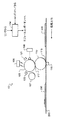
さて添付図面を参照すると、図1および2は本発明の実施形態による電気記録プリンタエンジンを概略的に示している。図示された本発明の実施形態は、個々の受像部材への印刷のために配列された6個の像生成印刷モジュールを使用する電気記録装置を必要とするが、6個より少ない又は多いモジュールによる発明が使用されてもよい。他のタイプの電気記録モジュールで本発明が実行されてもよい。 Referring now to the accompanying drawings, FIGS. 1 and 2 schematically illustrate an electrographic printer engine according to an embodiment of the present invention. The illustrated embodiment of the present invention requires an electrical recording device that uses six image producing and printing modules arranged for printing on individual image receiving members, but with fewer or more than six modules. The invention may be used. The invention may be practiced with other types of electrical recording modules.
電気記録プリンタエンジン100は連続する電気記録印刷モジュール10A,10B,10C,10D,10E,10Fを有する。後述のように、印刷モジュールの各々は静電像を形成し、担体およびトナー粒子を有する現像剤を使用して静電像を現像し、現像後の像を受像部材200に転写する。現像剤のトナー粒子が着色されている場合、トナー粒子は「マーキング粒子」とも呼ばれる。受像部材は、像または既定パターンが印刷されることが望ましい用紙、厚紙、プラスチック、または他の材料でよい。
The electric
図1に示された電気記録印刷モジュール10は、図2に示された電気記録印刷エンジン100の電気記録印刷モジュール10A〜10Fの各々を代表するものである。電気記録印刷モジュール10は、一つ以上の多層の像または形状を生成するための複数の電子写真像形成サブシステムを含む。各印刷モジュールに含まれるのは、光伝導性の像形成部材(像形成シリンダ105の形で示されている)の表面を均一に静電気帯電させるための一次帯電サブシステム108である。光伝導性像形成部材を露光することにより均一な静電荷をイメージ通りに変化させて各層に関して多層の(分離)静電潜像を形成するための露光サブシステム106が設けられている。像通りに露光された光伝導性像形成部材を現像する現像ステーションサブシステム107が設けられている。光伝導性像形成部材から第1転写ニップ117を通って中間転写部材110の表面へ、また中間転写部材110から第2転写ニップ115を通って受像部材200へ、それぞれの層(分離)像を転写するため、中間転写部材110が設けられている。
The electric recording printing module 10 shown in FIG. 1 represents each of the electric
図2に図示された電気記録印刷エンジンは、図1に図示された静電プリンタモジュール10の構造を各々が有する6個の静電プリンタモジュール10A,10B,10C,10D,10E,10Fを使用する。印刷モジュールの各々は、転写可能な単色の像を受像部材200に形成することが可能である。搬送ベルト210は、印刷エンジン100による処理のため受像部材200を搬送する。静電プリンタモジュール10A,10B,10C,10D,10E,10Fの印刷ニップを受像部材200が順番に移動すると、印刷モジュールは、生成された現像後の像を連続して受像部材に1回で転写する。
2 uses six
図示された印刷エンジン100は6個の静電印刷モジュールを含み、したがって1回で6個までの像が受像部材に形成される。例えば、印刷モジュール10A,10B,10C,10Dが像情報により駆動されて、ブラック、イエロー、マゼンタ、シアンの像をそれぞれ形成する。当該技術で周知のように、原色であるシアン、マゼンタ、イエロー、ブラック、およびその部分集合を様々な組合せで組み合わせることにより色のスペクトルが生成される。印刷モジュール10A,10B,10C,10Dの現像ステーションで使用される現像剤は、それぞれの印刷モジュールにより形成される像の色に対応するそれぞれの色の着色マーキング粒子を使用する。残る2個のモジュール10E,10Fは、色域を向上させるため代替触を有するマーキング粒子、透明層保護または隆起印刷の性能を提供する非着色粒子、またその何らかの組合せを備えるとよい。例えば、第5静電モジュールがレッドで着色されたマーキング粒子を有する現像剤を備え、第6静電モジュールが大きなサイズの非着色粒子を有する現像剤を備えてもよい。
The illustrated
所与の受像部材についての複数の静電印刷モジュール10A〜10Fによる連続した転写ステップの完了に続いて、受像部材に融着ステップが実施されて現像後の多色像を受像部材に融着する。融着ステップは、受像部材に熱および/または圧力を付与する。
Following completion of successive transfer steps by a plurality of
例えば、搬送ベルト210は、多色像を含む受像部材200を融着アセンブリ30まで移動させることができる。融着アセンブリ30は、間に融着ニップを形成して熱および圧力を受像部材200に印加する加熱融着ローラ31と対向する圧力ローラ32とを含む。用途に応じて、融着アセンブリがシリコンオイルなどの融着オイルを融着ローラ31に塗着してもよい。現像および融着プロセスの付加的な詳細は、参考として取り入れられているThomas N.Tombs,et al.の名で2008年7月3日に公開された米国公報第2008/0159786号に記載されている。
For example, the
示された例では、融着のための処理速度と隆起した印刷像を形成するための処理速度とが同じになるように、印刷モジュールで受像部材200を搬送するためと融着ステップで受像部材200を移動させるために同じ搬送ベルト210が用いられる。本発明は単一の処理速度による実施には限定されず、像を形成するのと像を融着するのに別の搬送機構が設けられて像の形成および融着の処理速度が単独で設定されてもよい。
In the illustrated example, the image receiving member is used for conveying the
一つ以上のコンピュータを含み、電気記録プリンタエンジン100と関連する様々なセンサからの信号に応じてそれぞれの部品にタイミング制御信号を提供し、よく理解された周知の使用法に従って様々な部品の制御を行って装置の制御パラメータを処理する論理制御ユニット123を、印刷エンジン100が含む。論理制御ユニット123は、印刷モジュール10A,10B,10C,10D,10E,10Fの各々のために個別の論理制御部品124を含むとよい。この制御システムは、隆起印刷物または隆起像の定着とも呼ばれる隆起印刷物の印刷および融着を実施するすべての関連の設定点とともに融着装置および用紙経路速度の制御を可能にする。
A timing control signal is provided to each component in response to signals from various sensors associated with the
本発明の原理によれば、隆起情報を印刷してこの隆起トナーの融着を向上させるためのプロセス、および/または印刷プロセスのパラメータが調節されることで、隆起像を作成するのに必要とされる大きなトナー粒子および/またはトナー塊がアーティファクトなしで印刷媒体に適切に付着するように、融着装置の処理速度を効果的に低下させて長い滞留時間を可能にする。後述する一実施形態では、広範囲のタイプの用紙に隆起像が適切に融着されるように、速度切替え技術が用いられて融着装置(ある実施形態ではEPプロセス)の処理速度を減速させる。この減速はジョブ全体の印刷速度を自動的に低下させることにより行われる、および/または、代替的には、隆起印刷を可能にするトナーを含有する乾燥インクステーションの存在をプリンタが検出した時に、低速で印刷を行うようにモードを変更する。他の実施形態では、新たな速度での印刷に最適である適切な融着およびEP設定点をプリンタが変更する。これらの設定点は、融着設定点、像を書き込むための書込み設定点、給紙関連の設定点、トナー給送および混合装置に関連する設定点、そして光伝導体および印刷関連の態様に関連する設定点を制御するものを含む、以下のうち一つまたはすべてを含む。 In accordance with the principles of the present invention, the process for printing the bump information to improve the fusing toner fusing and / or the parameters of the printing process are adjusted to produce the bump image required. The processing speed of the fusing device is effectively reduced to allow longer residence times so that the large toner particles and / or toner clumps that are applied will properly adhere to the print medium without artifacts. In one embodiment described below, a speed switching technique is used to reduce the processing speed of the fusing device (in one embodiment, the EP process) so that the raised image is properly fused to a wide range of types of paper. This deceleration is done by automatically reducing the print speed of the entire job, and / or alternatively when the printer detects the presence of a dry ink station containing toner that enables raised printing, Change the mode to print at low speed. In other embodiments, the printer changes the appropriate fusing and EP set points that are optimal for printing at the new speed. These set points are related to fusing set points, write set points for writing images, paper feed related set points, toner feed and mixing device related set points, and photoconductor and printing related aspects. Includes one or all of the following, including those that control setpoints:
本発明を用いて、これらの設定点を調節するとともに融着システムにおける受像体の用紙流れの速度を自動的に切り替えることにより、NexPress印刷機において83ppmで300gsmの用紙に高さ30μmまでの隆起像を含む印刷物が作成された。しかし、より高い速度で融着を行おうとする時には、融着装置が最も高い実用的な温度および圧力に設定されていても融着アーティファクト(低温オフセット)が発生した。後述する改善方法を用いると、プリンタは70ppmで300gsmの用紙に高さ50μmまでの隆起像を印刷できたが、さらに高い速度で融着させようとする時には、融着装置が最も高い実用的な温度および圧力に設定されていても融着アーティファクト(低温オフセット)が発生した。 Using the present invention to adjust these set points and automatically switch the speed of the receiver's paper flow in the fusing system, a raised image up to 30 μm in height on a 300 gsm paper at 83 ppm on a NexPress printer. A printed material containing was created. However, when attempting to fuse at a higher rate, fusing artifacts (low temperature offsets) occurred even when the fusing device was set to the highest practical temperature and pressure. Using the improvement method described below, the printer was able to print a raised image up to a height of 50 μm on a paper of 300 gsm at 70 ppm, but when trying to fuse at a higher speed, the fusing device is the most practical. Fusing artifacts (low temperature offset) occurred even when set to temperature and pressure.
電気記録印刷装置を用いて隆起印刷情報の選択的印刷を行うという目的のため、例えば触感を発生させる目的のため、着色マーキング粒子を含む印刷エンジンの一つ以上の印刷モジュールを用いて印刷像が生成され、印刷エンジンの被選択静電印刷モジュールに非着色の非マーキング粒子(例えば透明トナー)が提供されてもよい。マーキング粒子を用いて形成される印刷像の上部に非マーキング粒子を印刷することにより、隆起印刷情報、例えば隆起文字が受像部材に形成される。 For the purpose of selectively printing raised printing information using an electrographic printing device, for example for the purpose of generating a tactile sensation, the printed image is printed using one or more printing modules of a printing engine containing colored marking particles. Non-colored, non-marking particles (e.g., clear toner) may be generated and provided to the selected electrostatic printing module of the print engine. By printing non-marking particles on top of the printed image formed using the marking particles, raised printing information, for example raised characters, is formed on the image receiving member.
キャリア、マーキングおよび非マーキング粒子を含む現像剤粒子を指すのにここでは使用される粒子サイズという語は、Coulter,Inc.から販売されているCoulter Multisizerなど、従来の直径測定デバイスにより測定される平均体積重み付け直径を意味する。平均体積重み付け直径は、各粒子の質量の合計に質量および密度の等しい球体粒子の直径を掛けて合計粒子質量で割ったものである。 The term particle size, as used herein to refer to developer particles, including carrier, marking and non-marking particles, is described by Coulter, Inc. Means the average volume weighted diameter measured by a conventional diameter measuring device, such as the Coulter Multisizer sold by The average volume weighted diameter is the sum of the mass of each particle multiplied by the diameter of spherical particles of equal mass and density, divided by the total particle mass.
触感を付与するのに使用される原理は、少なくとも20μmの融着後積層高さを達成することであり、これはある環境において、受像部材の上のおよそ2.3mg/cm2の付着トナーから作成される。後述する高さの一部を達成できる付着量は後述の高さの後に提示されるが、これらは一実施形態に基づくものであって記載されたものと印刷条件が変わった場合には変化するという理解による。しかし、40〜50μm(5.5mg/cm2)以上の積層高さがいくつかの用途では望ましいことが多く、場合によっては、10mg/cm2以上の付着トナーから生じる高さを含む一層高い積層高さが必要とされる。 The principle used to impart tactile sensation is to achieve a post-fusing lamination height of at least 20 μm, which in some circumstances from approximately 2.3 mg / cm 2 of deposited toner on the image receiving member. Created. The amount of adhesion that can achieve a part of the height described later is presented after the height described later, but these are based on one embodiment and change when the printing conditions change from those described. Based on the understanding. However, stack heights of 40-50 μm (5.5 mg / cm 2 ) or more are often desirable in some applications, and in some cases, higher stacks including heights resulting from deposited toner of 10 mg / cm 2 or more. Height is required.
一般的な電気記録印刷モジュールでは、二成分現像剤システムを用いた現像ステップは、逆電荷問題による2層のトナー粒子の塗着に限定される。結果的に、8〜9μm(0.5mg/cm2)の単層のマーキング粒子を融着した後の積層高さは、その約半分(4μm)である。積層高さの積み重ねは、いくつかの印刷モジュールを用いてトナー粒子の層を積み重ねることにより達成される。しかし標準サイズの粒子を用いて積層高さを増すと、着色カラー載置モジュールに有効な印刷モジュールの数を制限するだろう。したがって、8〜9μm(0.5mg/cm2)より実質的に大きな粒子が使用されると、20μmより大きな融着後積層高さを有する隆起印刷が得られる。 In a typical electrographic printing module, the development step using a two-component developer system is limited to the application of two layers of toner particles due to the reverse charge problem. As a result, the stacking height after fusing 8-9 μm (0.5 mg / cm 2 ) single layer marking particles is about half (4 μm). Stack height stacking is achieved by stacking layers of toner particles using several printing modules. However, increasing the stacking height using standard size particles would limit the number of printing modules available for the colored color mounting module. Thus, if particles substantially larger than 8-9 μm (0.5 mg / cm 2 ) are used, a raised print having a post-fusion lamination height greater than 20 μm is obtained.
20μmより大きなトナー粒子を有する現像剤を使用するための技術が、隆起印刷を行うのに用いられるとよい。一般的に、このような粒子を使用する電気記録印刷モジュールはモジュールごとに2層を形成することができ、20μm(2.3mg/cm2)の粒子による2層から、約20μm(2.3mg/cm2)の融着後積層高さが得られる。 Techniques for using a developer having toner particles larger than 20 μm may be used to perform ridge printing. In general, an electrographic printing module using such particles can form two layers per module, from two layers with 20 μm (2.3 mg / cm 2 ) particles to about 20 μm (2.3 mg). / Cm 2 ) post-fusion stacking height is obtained.
本発明の原理によれば、一回に一つ以上の利用可能な電気記録印刷モジュールを用いて印刷像が受像部材に転写される。最高品質を有する印刷像を形成するため、8〜9μm(0.5mg/cm2)未満の標準的な汎用体積平均直径を有する小さな着色マーキング粒子の層を用いて、印刷像が形成される。 In accordance with the principles of the present invention, a printed image is transferred to an image receiving member using one or more available electrographic printing modules at a time. To form a printed image with the highest quality, a printed image is formed using a layer of small colored marking particles having a standard universal volume average diameter of less than 8-9 μm (0.5 mg / cm 2 ).
印刷像は、複数の電気記録印刷モジュールを用いることで形成される多色印刷像でよい。図2を参照すると、電気記録印刷エンジン100を用いることにより、電気記録印刷モジュール10Aはイエロー(Y)のトナー分離像を形成し、電気記録印刷モジュール10Bはマゼンタ(M)のトナー分離像を形成し、10Cはシアン(C)のトナー分離像を形成し、一方、10Dはブラック(K)のトナー分離像を形成できる。C,Y,M,Kの像の使用は、色のスペクトルを有する印刷像の生成を可能にするが、他の色を用いて発明が実施されてもよい。
The printed image may be a multicolor printed image formed by using a plurality of electrorecording printing modules. Referring to FIG. 2, by using the electro-
印刷像のマーキング粒子およびキャリア粒子を用いた印刷のための現像剤に適切な電気記録プロセス設定点、制御パラメータ、およびアルゴリズムを用いて、電気記録印刷モジュール10A,10B,10C,10Dが制御される。設定点、制御パラメータ、およびアルゴリズムは、論理制御ユニット123の論理形成部で実行されるとよい。
The
電気記録印刷モジュール10A,10B,10C,10Dが用いられて印刷像の多色部分を受像部材200に送った後、残りの複数のモジュールが用いられて受像部材200の被選択エリアに隆起像を形成する。多色印刷モジュールを使用して受像部材に隆起像を一回で形成することにより、必要な触感を付与するための最終積層高さが得られる。
After the
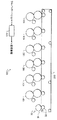
図3は、印刷モジュール10A,10B,10C,10Dを用いて形成される印刷像300を有する受像部材200を示している。図3に示されているように、印刷像は積層高さ「t」を有する。8〜9μm(0.5mg/cm2)のマーキング粒子が用いられる場合、融着プロセス後の印刷像積層高さは4と8μmの間でよい。
FIG. 3 shows an
電気記録印刷モジュール10Eおよび10Fの現像ステーションは、キャリア粒子と非着色の非マーキング粒子とを含む現像剤を供給する。隆起像の形成に用いられる非マーキング粒子は、印刷像の形成に用いられる標準サイズのマーキング粒子よりも実質的に大きなサイズである。例えば、非着色トナー粒子の体積平均直径は、14μm以上の、好ましくは20μm(2.3mg/cm2の単位面積あたり質量)と50μm(5.5mg/cm2の単位面積あたり質量)との間、より好ましくは20μm(2.3mg/cm2の単位面積あたり質量)と30μm(4.0mg/cm2の単位面積あたりの質量)μmの間でよい。
The development stations of the
印刷モジュール10Eを用いて、印刷エンジン100は第1隆起像を形成する。図4を参照すると、印刷像300が形成されている受像部材200の被選択エリアに第1隆起像302が形成されることが理解されるだろう。第1隆起像302を形成するための被選択エリアは、印刷像300からのマーキング粒子を有するエリアと重複するエリアを含むが、第1印刷像のためのマーキング粒子が載置されていないエリアに形成されてもよい。
Using the
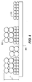
次に、印刷モジュール10Fを用いて、印刷エンジン100が第2隆起像を形成する。図5を参照すると、印刷像300と第1隆起像とが形成されている受像部材200の第2被選択エリアに第2隆起像304が形成されることが理解されるだろう。第2隆起像304を形成するための第2被選択エリアは、第1隆起印刷像302からのマーキング粒子を有するエリアと重複するエリアを含んでいるが、第1印刷像のためのマーキング粒子が存在していない受像部材のエリアと、第1隆起像のためのマーキング粒子が存在していないエリアとに形成されてもよい。
Next, the
第2隆起像304が第1隆起像302および印刷像と重複しているところでは、所望の触感を達成するための所望の積層高さTが得られるが、第1および第2隆起像の一方のみが形成されているエリアでは、これより低い高さT'が得られる。所望の積層高さを持つより大きな部分を生成するための大きな非マーキング粒子を用いると、印刷像を形成するのに適切な数の印刷モジュールを保持しながら、より大きな積層高さを達成する。さらに、印刷像を形成するための小さなマーキング粒子を用いると、透明な隆起像が印刷像に印刷される時でも高品質の印刷像が可能である。加えて、隆起効果が必要とされない像エリアに小さいサイズのマーキング粒子、隆起効果が望ましいエリアに大きな非マーキング粒子を用いると、隆起像と非隆起像を同時に生成することが可能になる。最後に、隆起効果が必要とされない像エリアに小さいサイズのマーキング粒子を用いると、小さいマーキング粒子が利用される時には必要な質量が少なくなるので、印刷物の製造コストを最小にする。
Where the second raised
発明の他の実施形態では、4個より少ない印刷モジュールを用いて多色印刷像が印刷受像体に形成されてもよい。図2を参照すると、電気記録印刷モジュール10Aはイエロー(Y)のトナー分離像を形成し、電気記録印刷モジュール10Bはマゼンタ(M)のトナー分離像を形成するのに対して、10Cはシアン(C)のトナー分離像を形成する。イエロー、マゼンタ、およびシアンの像を用いて多色像を印刷する時には、印刷像の所望エリアに等量のイエロー、マゼンタ、およびシアンを塗着することにより黒色が生成される。この場合、3個の印刷モジュール、すなわちモジュール10D,10E,10Fが受像体の被選択エリアに隆起像を形成するのに利用可能である。また別の実施形態では、単一の印刷モジュールが、標準サイズのマーキング粒子を用いて単色またはグレースケールの印刷像を受像部材に形成できる。例えば、印刷エンジン100の単一印刷モジュールを用いて単色の印刷像を形成すると、隆起像の形成に5個のモジュールを残しておける。例えば、印刷エンジン100が印刷モジュール10Aを用いて単色印刷像を受像部材200に形成した後に、受像部材200に隆起像を形成するのに、残りの複数のモジュールが利用可能である。図2に図示された印刷エンジンを用いると、印刷モジュール10B,10C,10D,10E,10Fのうち2個以上を用いて2,3,4,5個の隆起像が受像部材に連続的に形成され、100μmを充分に超える融着後の隆起印刷高さが可能となる。
In other embodiments of the invention, a multicolor printed image may be formed on a print receiver using fewer than four printing modules. Referring to FIG. 2, the electro-
プリンタ装置100による書込みのための像データは、単数または複数の色分離スクリーンジェネレータを含むラスターイメージプロセッサ(RIP)によって処理されるとよい。RIPの出力は、印刷像を形成するのに用いられるそれぞれの印刷モジュールの各々の露光ユニットへ色分離印刷データを伝達するため、フレームまたはラインバッファに記憶される。RIPおよび/または色分離スクリーンジェネレータは、プリンタ装置の一部であってもこれから遠隔位置にあってもよい。RIPにより処理される像データは、カラードキュメントスキャナまたはデジタルカメラから得られるか、プリンタにより適切に表示されるようにハーフトーン像データとなるように再処理される必要のある連続像を表す像データを一般的に含むコンピュータにより、あるいはメモリまたはネットワークから生成される。RIPは、所望のカラー印刷物を得るため、色補正を含む像処理プロセスを実施する。カラー像データはそれぞれの色に分離され、所望のスクリーン角度およびスクリーン線数を包含するマトリクスを用いてそれぞれの色のハーフトーンドット像データに、RIPによって変換される。RIPは適当にプログラムされたコンピュータおよび/または論理デバイスでよく、分離されたカラー像データを処理して、印刷に適したハーフトーン情報の形でレンダリングされた像データにするため、記憶または生成されたマトリクスおよびテンプレートを使用するのに適している。
Image data for writing by the
一つ以上の隆起像が着色印刷像と重複しているエリアでは、隆起像を通して見られる印刷像の見た目の色が変化する。受像部材全体で一貫して色が見える完成印刷品を生産するため、色分類を行うためのアルゴリズムは、印刷像が隆起像と重複されていないエリアとは異なる色分離を、印刷像が隆起像と重複されているエリアで生成するカラープロファイルを含む。一実施形態では、二つのカラープロファイルが作成される。第1カラープロファイルは、透明か非着色のトナーの上部被覆率が100%の場合、第2カラープロファイルは、透明トナーの上部被覆率が0%の場合のものである。ピクセル単位で、透明トナー像の平面に必要とされる被覆量に比例して、第3カラープロファイルが作成され、この第3カラープロファイルは第1および第2カラープロファイルの値を補間する。こうして、二つのカラープロファイルの混合演算が用いられて印刷値を生成する。好適な実施形態では、特定ピクセルに対応する二つのカラープロファイル値の線形補間が実施される。しかし、何らかの形の非線形補間が代わりに用いられてもよいことは言うまでもない。 In areas where one or more raised images overlap the colored printed image, the apparent color of the printed image seen through the raised image changes. In order to produce a finished printed product with consistently visible colors throughout the image receiving member, the algorithm for color classification uses a color separation that differs from areas where the printed image does not overlap with the raised image, Includes color profiles that are generated in overlapping areas. In one embodiment, two color profiles are created. The first color profile is obtained when the upper coverage of the transparent or non-colored toner is 100%, and the second color profile is obtained when the upper coverage of the transparent toner is 0%. A third color profile is created on a pixel-by-pixel basis in proportion to the amount of coverage required on the plane of the transparent toner image, and this third color profile interpolates the values of the first and second color profiles. Thus, a mixed value of the two color profiles is used to generate a print value. In the preferred embodiment, linear interpolation of two color profile values corresponding to a particular pixel is performed. However, it will be appreciated that some form of non-linear interpolation may be used instead.
隆起印刷が望ましくない受像部材のエリアに、透明のトナーオーバーコートが設けられてもよい。融着を向上させる方法の一つは、受像部材へのトナー付着量の大きな変化が見られる時に受像部材に良好な接着を行うことである。説明する方法は、多色トナー像を形成するステップと、一つ以上のカラートナー層のカラー付着量(CML)または非隆起付着量(NRML)と相関させて透明オーバーコート付着(OML)の量を決定するステップと、最大総付着量(TML)とニップ幅とにより決定される融着温度で透明トナーオーバーコートおよび多色トナー像を融着させて、融着装置オフセット緯度を最適化しながら受像部材への良好な接着を行うステップとを含む。OMLとして定義されて2.0mg/cm2より有意に低い非隆起像エリアにおける透明トナーの100%被覆率よりも有意に低い率で載置させても、保護オーバーコート層として機能することができ、高温オフセット破壊をさらに高温にすることで、すべての状況において、例えば、一つ以上の受像体が、オイルの吸収が容易でない高密度またはコーティング用紙である時に、融着装置オフセット緯度を向上させて、高いトナー付着量を隆起印刷用途に使用することを可能にすることが分かっている。本質的に、過熱および凝集破壊を回避するように、非隆起領域の総トナー付着量(NRMLとOMLの合計)が増加する。好ましくは、この被覆率は0%から60%の範囲であり、正確な被覆率は、不透明トナーの付着量(NRML)とともに、融着装置サブシステム、トナー材料、および受像部材の特徴を示す他の要因に応じたものである。概して、保護オーバーコート層の面積あたり付着量(OML)は%被覆率に対して非線形であるため、50%被覆率は100%被覆率と関連する付着量の1/2より実質的に低いことに注意すること。この保護層の別の利点は、隆起および非隆起像エリアの間で観察される色ずれの減少である。非隆起像エリアにおける透明トナーの低被覆率でも、融着時のトナー流れを減少されるのに充分であり、ゆえに隆起像エリアで観察されるものに一層類似した色ずれとなり、色ずれは保護層のないCMYKトナー付着部について測定される。 A transparent toner overcoat may be provided in areas of the image receiving member where ridge printing is not desired. One method for improving the fusion is to perform good adhesion to the image receiving member when a large change in the amount of toner adhering to the image receiving member is observed. The described method includes the steps of forming a multicolor toner image and the amount of transparent overcoat adhesion (OML) as a function of color adhesion (CML) or non-raised adhesion (NRML) of one or more color toner layers. And fusing the transparent toner overcoat and the multicolor toner image at a fusing temperature determined by the maximum total adhesion (TML) and the nip width, and receiving the image while optimizing the fusing device offset latitude. Providing good adhesion to the member. It can function as a protective overcoat layer even if it is placed at a rate significantly lower than 100% coverage of transparent toner in a non-raised image area defined as OML and significantly lower than 2.0 mg / cm 2. By increasing the high temperature offset failure, the fusing device offset latitude is improved in all situations, for example when one or more receivers are high density or coated paper that does not readily absorb oil. Thus, it has been found that high toner deposits can be used for raised printing applications. In essence, the total toner deposit (total NRML and OML) in the non-raised areas is increased to avoid overheating and cohesive failure. Preferably, the coverage is in the range of 0% to 60%, and the exact coverage, together with the amount of opaque toner deposited (NRML), is indicative of the characteristics of the fuser subsystem, toner material, and image receiving member. It depends on the factors. In general, the coverage per area (OML) of the protective overcoat layer is non-linear with respect to% coverage, so that 50% coverage is substantially lower than 1/2 of the coverage associated with 100% coverage. Please be careful. Another advantage of this protective layer is the reduction in color shift observed between the raised and non-raised image areas. Even a low coverage of clear toner in the non-lifted image area is sufficient to reduce toner flow during fusing, thus resulting in a color shift that is more similar to that observed in the raised image area and protecting the color shift. Measured for CMYK toner deposits without a layer.
隆起像を印刷するための像データは、いくつかの方法で作成される。一実施形態において、印刷像の、或るタイプのオブジェクトに対応するように印刷像情報から隆起像データが生成される。例えば、テキストオブジェクトが隆起印刷で印刷されるように、テキストオブジェクトに対応するように隆起像データが生成されるとよい。この場合、印刷モジュールのデジタルフロントエンドが、対応する数の隆起像を受像部材に形成するのに用いられる複数の印刷モジュールの露光ユニットを駆動するためのデータを生成する。印刷像と完全に重複するように隆起像が形成される。この場合、隆起像情報についてのデータが再び、印刷像を印刷するためのカラーまたはモノクロのデータから導出されるが、印刷像を形成するためのエリア全体に隆起像が形成されるように計算される。例えば、CYMK印刷像が形成される場合には、C,Y,M,Kのいずれかの像情報が非ゼロ値であるピクセルまたはエリアの値を持つように、隆起情報が生成される。 Image data for printing a raised image is created by several methods. In one embodiment, raised image data is generated from the printed image information to correspond to a certain type of object in the printed image. For example, the raised image data may be generated so as to correspond to the text object so that the text object is printed by the raised printing. In this case, the digital front end of the printing module generates data for driving the exposure units of the plurality of printing modules used to form a corresponding number of raised images on the image receiving member. A raised image is formed so as to completely overlap the printed image. In this case, the data about the raised image information is again derived from the color or monochrome data for printing the printed image, but is calculated so that the raised image is formed over the entire area for forming the printed image. The For example, when a CYMK print image is formed, the ridge information is generated so that the image information of any one of C, Y, M, and K has a non-zero value pixel or area value.
触感像の可変データ印刷を可能にするパターンを含有する適当なデータベースから隆起データが検索され、背景テクスチャは例えば、画家のキャンバス、アクリルペインティング、バスケットボール(豚革)、砂岩、サンドペーパー、布、カーペット、羊皮紙、皮膚、毛皮、または板目の印象を提供するとよい。パターンを形成する位置が印刷像のデータと無関係に特定されて、受像部材の特定エリアにテクスチャが形成されてもよい。 Uplift data is retrieved from a suitable database containing patterns that allow variable data printing of tactile images, background textures such as painter canvas, acrylic painting, basketball (pig leather), sandstone, sandpaper, cloth, It may provide an impression of carpet, parchment, skin, fur, or grain. The position where the pattern is formed may be specified regardless of the print image data, and the texture may be formed in a specific area of the image receiving member.
以下の例では印刷像と隆起像とを提供する特定モジュールが記載されたが、このような実施に発明は限定されない。例えば、隆起像を形成するための被選択エリアが印刷像を形成するためのエリアと重複しなくてもよい。別の例としては、印刷像を含まない受像部材の部分に触感像を表示することが望ましいことがある。このような場合、印刷像と隆起像とを形成するのにいかなる順序でモジュールが用いられてもよい。 In the following example, a specific module for providing a printed image and a raised image has been described, but the invention is not limited to such implementation. For example, the selected area for forming the raised image may not overlap with the area for forming the print image. As another example, it may be desirable to display a tactile image on a portion of the image receiving member that does not include a printed image. In such cases, the modules may be used in any order to form the printed image and the raised image.
他方、隆起テキストなどの隆起印刷を必要とする用途では、隆起像を形成する前に、隆起印刷を必要とするエリアの受像部材に印刷像が形成される。隆起印刷を1回で形成する時には、隆起印刷を形成するために選択されるモジュールは、印刷像の形成に続いて透明トナーを塗着するように選ばれる。 On the other hand, in applications that require bulge printing, such as bulge text, a printed image is formed on an image receiving member in an area that requires bulge printing before the bulge image is formed. When forming the ridge print in one pass, the module selected to form the ridge print is selected to apply a clear toner following the formation of the printed image.
さらに、6個の印刷モジュールを有する印刷エンジンの例を用いて発明が説明されるが、印刷モジュールの数は一例であって、別の数の印刷モジュールを有する装置によって発明が実施されてもよい。 Furthermore, although the invention is described using an example of a print engine having six printing modules, the number of printing modules is an example, and the invention may be implemented by an apparatus having a different number of printing modules. .
加えて、隆起像を形成するための現像剤は、着色されていない非マーキング粒子の塗着として説明された。代替実施形態において、隆起像を形成するための現像剤は、印刷像を形成するためのマーキング粒子よりも実質的に大きなサイズを有する着色トナー粒子を含有してもよい。 In addition, the developer for forming the raised image has been described as application of non-colored non-marking particles. In an alternative embodiment, the developer for forming the raised image may contain colored toner particles having a substantially larger size than the marking particles for forming the printed image.
複数の電気記録モジュールにおいて実質的に大きなサイズのマーキング粒子を用いて隆起像を印刷する時には、一つ以上の電気記録プロセス設定点または演算アルゴリズムを変更して、結果的に得られる印刷の性能、信頼性、および/または像品質を最適化すると好都合である。隆起情報を印刷する時の所定値に代わるものとして電気記録プリンタで制御される電気記録プロセス設定点(演算アルゴリズム)の値の例は、例えば、融着温度、融着ニップ幅、融着ニップ圧力、光伝導性部材への像形成電圧、トナー付着ステーション転写圧力、像転写電圧および像転写電流、および融着プロセス中に印加される融着オイルの量を含む。隆起情報印刷物を作成する電気記録装置では、隆起情報を印刷する時に所定の設定点(あるいは制御パラメータまたはアルゴリズム)が用いられる場合に特殊な動作モードが提供される。すなわち、電気記録印刷装置が非隆起情報像を印刷する時には、第1組の設定点/制御パラメータが利用されるのである。次に、電気記録印刷装置が隆起情報像を印刷するためモードを変更する時には、第2組の設定点/制御パラメータが利用される。 When printing a raised image using marking particles of substantially large size in multiple electrorecording modules, one or more electrorecording process set points or arithmetic algorithms can be changed to result in printing performance, It is advantageous to optimize reliability and / or image quality. Examples of values for the electrical recording process set point (arithmetic algorithm) controlled by the electrical recording printer as an alternative to a predetermined value when printing uplift information include, for example, fusing temperature, fusing nip width, fusing nip pressure Image forming voltage to the photoconductive member, toner deposition station transfer pressure, image transfer voltage and image transfer current, and the amount of fusing oil applied during the fusing process. An electrical recording apparatus that produces a raised information print provides a special mode of operation when a predetermined set point (or control parameter or algorithm) is used when printing raised information. That is, the first set of set points / control parameters is used when the electrographic printing apparatus prints a non-lifting information image. The second set of set points / control parameters is then utilized when the electrographic printing device changes modes to print the raised information image.
電気記録融着プロセスでは、融着したトナーが受像部材の基板繊維を貫通せずに、全体として用紙基板上に残る。融着ステップは、付着トナーの高さをおよそ二分の一だけ減少させられる。上記のように、受像部材にトナーを効果的に定着させる融着プロセスのパラメータは、隆起印刷に用いられる隆起印刷モジュールの数と印刷および隆起像の形成に用いられるマーキング粒子のサイズとともに、受像部材の物理的および熱的性質に応じて変化する。加えて、隆起情報を印刷するための一組以上の融着パラメータなどのパラメータは、印刷エンジンと関連するメモリに記憶され、受像部材のタイプ、所望の融着後積層高さ、融着プロセス速度、印刷像の形成に用いられる印刷モジュールの数、隆起および印刷像の形成に用いられるトナー粒子のサイズおよびタイプ、隆起像の形成に用いられる印刷モジュールの数などのパラメータに基づいて、選択および適用される。パラメータはオペレータによって手作業で入力されても、印刷モジュールと関連するセンサにより自動的に決定されても、また手動入力とパラメータ検知との組合せが使用されてもよい。 In the electric recording and fusing process, the fused toner remains on the paper substrate as a whole without penetrating the substrate fibers of the image receiving member. The fusing step reduces the height of the deposited toner by approximately one-half. As described above, the parameters of the fusing process for effectively fixing the toner to the image receiving member include the number of raised printing modules used for raised printing and the size of the marking particles used for printing and forming the raised image. It varies depending on the physical and thermal properties of the. In addition, parameters such as one or more sets of fusing parameters for printing uplift information are stored in a memory associated with the print engine, and the type of image receiving member, desired post-fusing stack height, fusing process speed. Selection and application based on parameters such as the number of printing modules used to form the printed image, the size and type of toner particles used to form the bumps and the printed image, the number of printing modules used to form the raised image Is done. The parameters may be entered manually by an operator, automatically determined by sensors associated with the printing module, or a combination of manual input and parameter sensing may be used.
好ましくは、隆起情報を印刷するのに用いられるマーキング粒子は、印刷情報を形成するための粒子よりも実質的に大きい汎用かつ平均的な平均体積重み付け直径を有する。例えば、印刷情報を印刷するためのマーキング粒子は9μm未満(8μmなど)の標準的な汎用の平均的な平均体積を有するのに対して、隆起情報を印刷するためのマーキング粒子は、12μmと30μmの間(21と30μmの間など)の汎用かつ平均的な平均体積重み付け直径を有する。 Preferably, the marking particles used to print the ridge information have a general and average average volume weighted diameter that is substantially larger than the particles for forming the printed information. For example, marking particles for printing printing information have a standard universal average average volume of less than 9 μm (such as 8 μm), whereas marking particles for printing raised information are 12 μm and 30 μm With a general and average mean volume weighted diameter between (eg between 21 and 30 μm).
印刷像情報を形成するのに8μmマーキング粒子を用いるとともに隆起像情報を印刷するのに20μm粒子を用いる本発明の実施形態による電気記録印刷エンジンの例では、印刷像と第1および第2隆起像とが形成されてその結果として融着後積層高さが約50μmとなるエリアでは、5mg/cm2までの付着トナー被覆率が達成される。対照的に、8μmマーキング粒子を用いるいくつかの像形成モジュールを適用する時には、形成される各層について約0.4から0.5mg/cm2の付着被覆率が一般的である。8μm粒子を用いて所望の積層高さを達成するのに充分な印刷モジュールを使用すると、カラートナーを付着させるために利用可能なモジュールの数を厳しく制限して、最終的な像で実現可能な色域を減少させる。 In an example of an electrographic printing engine according to an embodiment of the invention that uses 8 μm marking particles to form printed image information and 20 μm particles to print raised image information, the printed image and first and second raised images As a result, an adhesion toner coverage of up to 5 mg / cm 2 is achieved in an area where the lamination height after fusion is about 50 μm. In contrast, when applying several imaging modules using 8 μm marking particles, a deposition coverage of about 0.4 to 0.5 mg / cm 2 is common for each layer formed. Using enough printing modules to achieve the desired stack height with 8 μm particles can be achieved in the final image, severely limiting the number of modules available for depositing color toner. Reduce the color gamut.
他方、大きな非マーキング粒子を用いる多数の印刷モジュールを使用して隆起印刷像を形成することにより、印刷エンジンに利用可能な印刷モジュールを用いて融着後積層高さを上昇させることができる。例えば、大きな非マーキング粒子を用いて隆起印刷像を形成するのに4または5個のモジュールを用いることにより、電気記録印刷を用いて100μm以上の定着後積層高さが可能である。 On the other hand, by using a large number of printing modules with large non-marking particles to form a raised printed image, the stack height after fusing can be increased using printing modules available for the print engine. For example, by using 4 or 5 modules to form raised print images using large non-marking particles, post-fixing stack heights of 100 μm or more are possible using electrographic printing.
上述した例では、隆起像を印刷するための大きなサイズのトナー粒子が非着色の非マーキング粒子として記載されている。本発明は、隆起像を設けるのに用いられる大きなサイズの着色粒子で実施されてもよい。例えば、1種類以上の大きなサイズの非マーキング粒子を大きなサイズの着色マーキングトナー粒子と置き換えることを特徴とする装置を用いて、特定色の隆起テキストが形成されてもよい。 In the example described above, large size toner particles for printing raised images are described as non-colored non-marking particles. The present invention may be practiced with large sized colored particles used to provide raised images. For example, raised text of a particular color may be formed using an apparatus that is characterized by replacing one or more large sized non-marking particles with large sized colored marking toner particles.
さらに、上述の例では、隆起像を印刷するための各モジュールが、同じ体積平均直径を有するトナー粒子を使用した。本発明はこの方法での実施に限定されない。印刷モジュールの各々により使用される体積平均直径が標準サイズの粒子よりも実質的に大きいと仮定して、隆起像の形成に用いられる複数の印刷モジュールが異なるサイズのトナー粒子を使用してもよい。例えば、二つの隆起像を受像部材に形成する時に、第1隆起像を印刷するためのトナー粒子は、第2隆起像を印刷するためのトナー粒子よりも実質的に大きくてよい。 Furthermore, in the above example, each module for printing the raised image used toner particles having the same volume average diameter. The present invention is not limited to implementation in this manner. Assuming that the volume average diameter used by each of the printing modules is substantially larger than the standard size particles, the multiple printing modules used to form the raised image may use different size toner particles. . For example, when forming two raised images on the image receiving member, the toner particles for printing the first raised image may be substantially larger than the toner particles for printing the second raised image.
隆起像を作成するのに必要とされる大きなトナー粒子および/またはトナー塊がアーティファクトなしで印刷媒体に適切に付着するように融着装置の処理速度を減速させて長い滞留時間を可能にすることを含む、電気記録プリンタで受像部材に隆起印刷を施すための改善融着方法を、図6を参照して説明する。この方法は図1および2に図示された装置を用い、電子写真プリンタの性能を活用するためのステップを含む。この方法は一つ以上の制御装置により実行されるとよい。方法は、隆起トナーの効果的な融着を実施する一つ以上の速度関連の融着装置パラメータの制御を含む。これらの設定点は、非隆起トナーあるいは非隆起トナー像または印刷物と呼ばれることのある隆起トナーを含まない像の印刷に使用されるものとは異なっている。 To reduce the fusing device processing speed and allow longer residence times so that the large toner particles and / or toner mass required to create the raised image will properly adhere to the print media without artifacts. An improved fusing method for applying raised printing to an image receiving member with an electric recording printer will be described with reference to FIG. This method uses the apparatus illustrated in FIGS. 1 and 2 and includes steps for exploiting the performance of the electrophotographic printer. This method may be executed by one or more control devices. The method includes control of one or more speed-related fuser parameters that effect effective fusing of the raised toner. These set points are different from those used for printing non-raised toner or non-raised toner images or images that do not contain raised toner, sometimes called prints.
例えば、隆起印刷が用いられる時には、質量/単位面積またはこのパラメータについての高さ関連値に基づいて受像体の速度が設定されるとよい。こうして一実施形態では、融着装置の処理速度を効果的に低下させて長い滞留時間を可能にするため、隆起像を作成するのに必要とされる大きなトナー粒子および/またはトナー塊がアーティファクトなしで印刷媒体に適切に付着する。この方法の一実施形態では、融着装置(および実施形態によってはEPプロセス)の処理速度を低下させるのに速度切替え技術が用いられるため、広範囲のタイプの用紙に隆起像が適切に融着される。この実施形態は、参照テーブル(LUT)を用いるか、別のメモリデバイスが用いられて必要に応じて自動的な速度切替えを実行するとよい。 For example, when bulge printing is used, the speed of the receiver may be set based on mass / unit area or a height related value for this parameter. Thus, in one embodiment, the large toner particles and / or toner mass required to create the raised image is free of artifacts to effectively reduce the fusing device processing speed and allow longer residence times. To properly adhere to the print media. In one embodiment of this method, a speed switching technique is used to reduce the processing speed of the fusing device (and in some embodiments the EP process) so that the raised image is properly fused to a wide range of types of paper. The In this embodiment, a reference table (LUT) may be used, or another memory device may be used to perform automatic speed switching as required.
電気記録印刷方法600は、隆起情報を印刷するため電気記録法印刷エンジンの設定点が設定されるステップS605から始まる。すなわち、上述のように、受像部材への印刷が適切に定着されるように融着装置の設定点が調節されるのである。加えて、印刷エンジンにおいて受像部材を移動させるための処理速度が、隆起印刷が施されないプロセスとは異なるように設定される。一実施形態では、>2mg/cm2などの所定値より大きな単位面積あたり質量を有するイメージコンテンツ(隆起像、RI、コンテンツ)を印刷対象のページ(またはジョブ)が含むかどうかをS605で決定する。
The
プロセス600は、印刷像の形成および融着のためのパラメータおよび設定点が適用されるステップS610に続く。例えば、像形成電圧、トナー付着電圧、磁気ブラシ動作パラメータ、像転写電圧および像転写電流が、標準サイズのマーキング粒子を用いる現像剤の適用に適したものとして設定されるとよい。これらのパラメータおよび設定点は、印刷像を形成するためのモジュールに適用される。すなわち、一実施形態のS610では、所望の隆起像の単位面積あたり質量に基づいて決定ステップが速度パラメータを決定するのである。例えば、隆起像コンテンツが検出されると、隆起インクまたはトナー(RI)融着設定点まで融着装置速度を変化させる、例えば50%だけ速度を低下させる。隆起像を印刷する隆起情報を用いて隆起像を含む印刷像が受像部材に形成されるステップS615に、プロセス600は続く。
印刷像の形成に続いて、融着と非融着の両方の関連パラメータを含めて、隆起像を形成するためのパラメータ、値、設定点が、ステップS620で確定される。非融着パラメータは例えば、像形成電圧、トナー付着ステーション電圧、磁気ブラシ動作パラメータ、像転写電圧に加えて、用紙、中間および光伝導体の速度、そして像転写電流を含む。融着関連パラメータの一部は、例えば、温度、圧力、ニップ幅、そして融着部材関連速度といった融着関連部材の速度を含む。融着部材は、融着ローラ、融着ベルト、および固有転写デバイスの速度を含む。 Following the formation of the printed image, parameters, values, and set points for forming the raised image, including relevant parameters for both fusion and non-fusion, are determined in step S620. Non-fusion parameters include, for example, image forming voltage, toner deposition station voltage, magnetic brush operating parameters, image transfer voltage, as well as paper, intermediate and photoconductor speed, and image transfer current. Some of the fusing related parameters include, for example, the speed of the fusing related member such as temperature, pressure, nip width, and fusing member related speed. The fusing member includes the fusing roller, the fusing belt, and the intrinsic transfer device speed.
一実施形態において、隆起像を印刷するためのマーキング粒子は一般的に、印刷像を印刷するためのものより実質的に大きく、隆起像を形成するためのモジュールに適用される電気記録パラメータおよび設定点のいくつかは、印刷像の形成のためのモジュールに適用されるものと異なっているとよい。例えば、印刷エンジン100は、印刷モジュール10B,10C,10D,10E,10Fを用いて受像部材200に多色印刷像を形成できる。印刷モジュール10Aは、標準サイズより大きい第1トナー粒子(20μmマーキング粒子など)を用いて第1隆起像を形成するのに用いられ、印刷モジュール10Eは、標準サイズより大きな第2トナー粒子(30μmマーキング粒子など)を用いて第2隆起印刷像を形成するのに用いられるとよい。
In one embodiment, the marking particles for printing the raised image are generally substantially larger than for printing the printed image, and the electrorecording parameters and settings applied to the module for forming the raised image Some of the points may be different from those applied to the module for forming the printed image. For example, the
すなわちS620では、RI速度関連の融着装置設定点を適用して隆起像コンテンツを含む像の融着を実施することにより、プリンタシステムが受像部材に像を定着させる。隆起像を作成するのに必要とされる大きなトナー粒子および/または大きなトナー塊がアーティファクトなしで印刷媒体に適切に付着するように、質量/単位面積または高さに基づいて速度が設定されることで、融着装置の処理速度を効果的に低下させて長い滞留時間時間を可能にする。 That is, in S620, the printer system fixes the image on the image receiving member by applying the RI speed-related fusing device set point and fusing the image including the raised image content. The speed is set based on mass / unit area or height so that the large toner particles and / or large toner mass required to create the raised image will adhere properly to the print media without artifacts. Thus, it is possible to effectively reduce the processing speed of the fusion apparatus and to enable a long residence time.
また、受像部材の第1被選択エリアにおいて第1隆起像が受像部材に形成されて、受像部材の第2被選択エリアにおいて第2隆起像が形成されるように、プロセス600が継続するとよい。第1被選択エリアは第2被選択エリアと同じであってもよい。第1被選択エリアと第2被選択エリアとが、印刷像のすべてまたはいくつかの部分と重複してもよい。代替的に、印刷像と隆起像とが受像部材の別のエリアを占めてもよい。第1および第2隆起像の形成に続いて、印刷像および隆起像が受像部材に融着されて、組合せ像を定着させる。参考として取り入れられている同時係属の米国出願番号第12/404,485号に記載されているように6個を超えて印刷モジュールが用いられる時には、プロセス600に追加プロセスステップが加えられる。
Also, the
図7は、隆起印刷のための改善融着システムの別の実施形態を説明している。この実施形態では、隆起トナーの存在を検出するプリンタ、または隆起印刷を可能にするトナーを含む乾燥インクステーションを用いて、低速で印刷するようにモードを変化させることが融着向上に含まれる。これは自動化され、説明した他の方法とともに用いられるとよい。新たな速度での印刷に最適である適切な融着およびEP設定点が常に変更されるため、こうしてプリンタは隆起トナーの処理を常に行える。第1ステップS705は、ステップ605に関して上述した隆起トナー設定点を決定する。 FIG. 7 illustrates another embodiment of an improved fusing system for raised printing. In this embodiment, the fusing enhancement includes changing the mode to print at low speed using a printer that detects the presence of raised toner, or a dry ink station that contains toner that enables raised printing. This is automated and may be used with the other methods described. Thus, the printer is always able to handle raised toner, since the proper fusing and EP set points that are optimal for printing at new speeds are constantly changing. The first step S705 determines the raised toner set point described above with respect to step 605.
次にS710では、隆起像コンテンツが検出されると、融着速度、用紙経路速度、光伝導体表面速度、中間転写表面速度、および必要に応じて書出しプログラム露光時間および/または振幅、書込みプログラム線周波数始点、転写バイアス設定点(電圧およびまたは電流)、トナー付着ステーションバイアス設定点、トナー付着ステーション現像液給送速度、消去ランプ振幅、帯電バイアス設定点、仕上げ装置速度など他のEPプロセス関連値を含む、隆起像速度関連の設定点が変更される。上述したS615と同様に、ステップS715で隆起像が形成され、隆起トナー速度関連の融着装置設定点を適用して隆起像エリアを含む像の融着を実施することにより受像部材に像を定着させるステップS720において、像が融着される。隆起像を作成するのに必要とされる大きなトナー粒子および/またはトナー塊がアーティファクトなしで印刷媒体に適切に付着するように、質量/単位面積または高さに基づいて速度が設定されることで融着装置のプロセス速度を効果的に低下させて長い滞留時間を可能にする。 Next, in step S710, when raised image content is detected, the fusing speed, paper path speed, photoconductor surface speed, intermediate transfer surface speed, and optionally write program exposure time and / or amplitude, write program line. Other EP process related values such as frequency start point, transfer bias set point (voltage and / or current), toner application station bias set point, toner application station developer feed speed, erase ramp amplitude, charging bias set point, finishing device speed Including set points related to the raised image speed. Similar to S615 described above, a raised image is formed in step S715, and the image including the raised image area is fused by applying a fuser set point related to the raised toner speed to fix the image on the image receiving member. In step S720, the image is fused. The speed is set based on mass / unit area or height so that the large toner particles and / or toner mass required to create the raised image will adhere properly to the print media without artifacts. It effectively reduces the process speed of the fuser and allows for long residence times.
受像部材に隆起印刷を施すための別の電気記録印刷方法を、図8を参照して説明する。電気記録印刷方法は、装置を用いて実施可能である。 Another electro-recording printing method for performing raised printing on the image receiving member will be described with reference to FIG. The electrical recording printing method can be implemented using an apparatus.
広範囲の用紙タイプに隆起像が適切に融着されるように融着装置(および実施形態によってはEPプロセス)の処理速度を低下させる速度切替え技術を、この方法でも利用できる。電気記録印刷方法800は、電気記録法印刷エンジンの設定点が隆起情報の印刷のために設定されるステップS805から始まる。すなわち、上述のように、受像部材への印刷が適切に定着されるように、融着装置の設定点が調節されるのである。加えて、印刷エンジンにおいて受像部材を移動させるための処理速度が、隆起印刷が施されないプロセスとは異なるように設定される。一実施形態では、>2mg/cm2(隆起像、RI、コンテンツ)など既定値より高い単位面積あたり質量を有するイメージコンテンツを印刷対象ページ(またはジョブ)が含むかどうかをS805が判断する。
A speed switching technique that reduces the processing speed of the fusing device (and in some embodiments the EP process) so that the raised images are properly fused to a wide range of paper types can also be used in this method. The
隆起トナーの融着を実施する隆起情報プリンタ設定点に基づいて、必要な隆起トナー速度および追加の関連融着装置設定点が決定されるステップS810へ、プロセスが続く。次にステップS815では、隆起像を印刷する隆起情報を用いて隆起像が受像部材に形成され、所望の隆起像の単位面積あたり質量に基づいて速度パラメータを決定する。 The process continues to step S810 where the required ridge toner speed and additional associated fuser set points are determined based on the ridge information printer set point that performs ridge toner fusing. Next, in step S815, a raised image is formed on the image receiving member using the raised information for printing the raised image, and the velocity parameter is determined based on the mass per unit area of the desired raised image.
最後にステップS820では、隆起トナー速度関連の融着装置設定点を適用して非隆起トナーでなく隆起トナーの融着を実施することにより、受像部材に像が定着または融着される。質量/単位面積または高さに基づいて速度が設定されることで、対話式/自動的に効果的な減速または加速を行うため、隆起像を作成するのに必要とされる大きなトナー粒子および/またはトナー塊がアーティファクトなしで印刷媒体に適切に付着するように、融着装置の処理速度が異なる滞留時間時間を可能にする。 Finally, in step S820, an image is fixed or fused on the image receiving member by applying a fuser set point related to the raised toner speed to fuse the raised toner instead of the non-raised toner. The speed is set based on mass / unit area or height, so that the large toner particles and / or needed to create a raised image for interactive / automatic effective deceleration or acceleration. Or, the fusing device processing speed allows different residence time times so that the toner mass will properly adhere to the print media without artifacts.
10 電気記録印刷モジュール、30 融着アセンブリ、31 加熱融着ローラ、32 融着装置加圧ローラ、100 電気記録プリンタエンジン、105 光伝導性ドラム、106 露光ユニット、107 現像ステーション、108 帯電モジュール、110 中間転写部材ドラム、115 第2転写ニップ、117 第1転写ニップ、118 回転下方転写ドラム、121 均一静電電荷量測定器、122 露光後電荷量測定器、123 論理制御ユニット、124 モジュール論理制御コンポーネント、200 受像部材、210 搬送ベルト、300 印刷像、302 第1隆起像、304 第2隆起像。 DESCRIPTION OF SYMBOLS 10 Electric recording printing module, 30 Fusion assembly, 31 Heat-fusion roller, 32 Fusion apparatus pressurization roller, 100 Electric recording printer engine, 105 Photoconductive drum, 106 Exposure unit, 107 Developing station, 108 Charging module, 110 Intermediate transfer member drum, 115 second transfer nip, 117 first transfer nip, 118 rotating lower transfer drum, 121 uniform electrostatic charge measuring device, 122 post-exposure charge measuring device, 123 logic control unit, 124 module logic control component , 200 image receiving member, 210 conveying belt, 300 printed image, 302 first raised image, 304 second raised image.
Claims (20)
隆起像を有する印刷像を前記受像部材上の印刷像の第1隆起像エリアに電気記録方式で形成することと、
前記隆起像を含む前記印刷像を前記受像部材に定着させるための隆起融着値に、前記隆起像を含まない印刷像を定着させるための融着パラメータ値とは別の、隆起融着パラメータを設定することと、
隆起融着パラメータを設定するための融着アセンブリ制御装置による決定に基づいて、前記制御装置により制御される融着アセンブリにおいて前記受像部材を搬送することと、
前記隆起融着値を用いて、前記融着アセンブリにおける前記受像部材の搬送速度を調節して前記第1隆起像エリアを補正することと、
前記隆起融着パラメータ値を使用する融着装置を用いて、前記隆起像を含む前記印刷像を前記受像部材に定着させることと、
を包含する方法。 An electrorecording printing method for forming raised information on an image receiving member,
Forming a printed image having a raised image in a first raised image area of the printed image on the image receiving member by an electric recording method;
A raised fusing parameter for fixing the printed image including the raised image to the image receiving member is different from a fusing parameter value for fixing the printed image not containing the raised image. Setting,
Conveying the image receiving member in a fusing assembly controlled by the controller based on a determination by the fusing assembly controller to set a bulge fusing parameter;
Correcting the first raised image area by adjusting the conveying speed of the image receiving member in the fused assembly using the raised fused value;
Fixing the printed image including the raised image to the image receiving member using a fusing device using the raised fusing parameter values;
Including the method.
隆起像を載せている受像部材に熱および/または圧力を印加して、隆起像を含まない印刷像を融着させるための融着パラメータ値とは別である、前記隆起像を含む前記印刷像を前記受像部材に融着させるための隆起融着値に調節された隆起融着パラメータを用いて前記隆起像を前記受像部材に融着させる、ニップ関係にある一対のローラを有する融着アセンブリと、
前記一対のローラを回転させて前記ローラニップに駆動力を提供し、前記融着アセンブリにおいて前記受像部材を搬送するためのモータと、
前記融着アセンブリにおいて搬送される前記受像部材の速度を制御するための機構であって、
様々な所望条件において特定タイプの受像部材を融着させるのに必要とされるパラメータを記憶するための入力デバイスと、
前記入力デバイスからの情報と、特定の受像部材タイプおよび所定条件の選択とに基づいて、隆起融着パラメータを含む融着装置制御パラメータを決定するためのデバイスと、
前記決定デバイスによる決定に基づいて隆起融着パラメータを隆起融着値に設定するためと、前記一対のローラを回転させるための前記モータを調節して前記融着アセンブリにおける前記受像部材の搬送速度を設定し前記隆起像を補正するための融着アセンブリ制御装置と、
を包含する速度制御機構と、
を包含する電気記録プリンタ。 An electric recording printer for forming uplift information on an image receiving member,
The printed image including the raised image, which is different from the fusing parameter value for fusing the printed image not including the raised image by applying heat and / or pressure to the image receiving member carrying the raised image. A fusing assembly having a pair of rollers in a nip relationship for fusing the raised image to the image receiving member using a raised fusing parameter adjusted to a raised fusing value for fusing the image receiving member to the image receiving member; ,
A motor for rotating the pair of rollers to provide a driving force to the roller nip and transporting the image receiving member in the fusing assembly;
A mechanism for controlling the speed of the image receiving member conveyed in the fusion assembly,
An input device for storing parameters required to fuse a particular type of image receiving member in various desired conditions;
A device for determining fuser control parameters, including raised fusion parameters, based on information from the input device and selection of a particular image receiving member type and predetermined conditions;
Based on the determination by the determination device, the bulge fusing parameter is set to the bulge fusing value, and the motor for rotating the pair of rollers is adjusted to adjust the conveying speed of the image receiving member in the fusing assembly. A fusion assembly controller for setting and correcting the raised image;
A speed control mechanism including:
Including electric recording printer.
受像部材を収容することと、
第1印刷モジュールにより、第1標準サイズマーキング粒子を前記受像部材に選択的に塗着することと、
第2印刷モジュールにより、前記標準サイズマーキング粒子より大きな体積平均直径を有する第1大サイズトナー粒子を前記受像部材に選択的に塗着することと、
第3印刷モジュールにより、前記標準サイズマーキング粒子よりも実質的に大きな体積平均直径を有する第2大サイズトナー粒子を前記受像部材に選択的に塗着することと、
前記印刷像および前記隆起像を前記受像部材に定着させるための隆起融着パラメータを、前記隆起像を含まない印刷像を定着させるための値とは別の変更値に設定するとともに、前記変更パラメータ値を使用する融着装置を用いて前記印刷像および前記隆起像を前記受像部材に定着させることと、
を包含する方法。 An electrical recording printing method for forming uplift information,
Accommodating an image receiving member;
Selectively applying first standard size marking particles to the image receiving member by a first printing module;
Selectively applying to the image receiving member first large size toner particles having a volume average diameter larger than the standard size marking particles by a second printing module;
Selectively applying second large size toner particles having a volume average diameter substantially larger than the standard size marking particles to the image receiving member by a third printing module;
The ridge fusion parameter for fixing the print image and the ridge image to the image receiving member is set to a change value different from the value for fixing the print image not including the ridge image, and the change parameter Fixing the printed image and the raised image to the image receiving member using a fusing device using values;
Including the method.
Applications Claiming Priority (3)
| Application Number | Priority Date | Filing Date | Title |
|---|---|---|---|
| US12/553,284 | 2009-09-03 | ||
| US12/553,284 US8320784B2 (en) | 2009-09-03 | 2009-09-03 | Enhanced fusing of raised toner using electrography |
| PCT/US2010/046574 WO2011028557A1 (en) | 2009-09-03 | 2010-08-25 | Enhanced fusing of raised toner using electrography |
Publications (2)
| Publication Number | Publication Date |
|---|---|
| JP2013504091A true JP2013504091A (en) | 2013-02-04 |
| JP2013504091A5 JP2013504091A5 (en) | 2013-10-03 |
Family
ID=43084469
Family Applications (1)
| Application Number | Title | Priority Date | Filing Date |
|---|---|---|---|
| JP2012527911A Withdrawn JP2013504091A (en) | 2009-09-03 | 2010-08-25 | Improvement of fusing toner using electro-recording method |
Country Status (5)
| Country | Link |
|---|---|
| US (1) | US8320784B2 (en) |
| EP (1) | EP2473883A1 (en) |
| JP (1) | JP2013504091A (en) |
| CN (1) | CN102483599A (en) |
| WO (1) | WO2011028557A1 (en) |
Cited By (2)
| Publication number | Priority date | Publication date | Assignee | Title |
|---|---|---|---|---|
| JP2013222196A (en) * | 2013-03-28 | 2013-10-28 | Ricoh Co Ltd | Production method of printed matter, and printed matter |
| JP2013238733A (en) * | 2012-05-15 | 2013-11-28 | Ricoh Co Ltd | Image forming apparatus |
Families Citing this family (3)
| Publication number | Priority date | Publication date | Assignee | Title |
|---|---|---|---|---|
| US8619329B2 (en) * | 2010-11-12 | 2013-12-31 | Xerox Corporation | Print smoothness on clear toner enabled systems |
| WO2013066289A1 (en) * | 2011-10-31 | 2013-05-10 | Hewlett-Packard Development Company, L.P. | In-line integrated raised printing |
| US9213255B1 (en) | 2014-08-27 | 2015-12-15 | Eastman Kodak Company | Printing tactile images with improved image quality |
Family Cites Families (5)
| Publication number | Priority date | Publication date | Assignee | Title |
|---|---|---|---|---|
| US7298391B2 (en) * | 2004-09-13 | 2007-11-20 | Marvell International Technology Ltd. | Laser printer for Braille |
| US7184679B2 (en) | 2005-04-28 | 2007-02-27 | Eastman Kodak Company | Receiver member speed control through a fuser assembly of a reproduction apparatus |
| US7428389B2 (en) | 2006-05-24 | 2008-09-23 | Kabushiki Kaisha Toshiba | Fixing device for color image forming apparatus and control method |
| US8358957B2 (en) * | 2006-12-27 | 2013-01-22 | Eastman Kodak Company | Selective printing of raised information by electrography |
| US7783243B2 (en) | 2007-12-18 | 2010-08-24 | Eastman Kodak Company | Enhanced fuser offset latitude method |
-
2009
- 2009-09-03 US US12/553,284 patent/US8320784B2/en active Active
-
2010
- 2010-08-25 WO PCT/US2010/046574 patent/WO2011028557A1/en active Application Filing
- 2010-08-25 EP EP10749965A patent/EP2473883A1/en not_active Withdrawn
- 2010-08-25 JP JP2012527911A patent/JP2013504091A/en not_active Withdrawn
- 2010-08-25 CN CN201080038796XA patent/CN102483599A/en active Pending
Cited By (2)
| Publication number | Priority date | Publication date | Assignee | Title |
|---|---|---|---|---|
| JP2013238733A (en) * | 2012-05-15 | 2013-11-28 | Ricoh Co Ltd | Image forming apparatus |
| JP2013222196A (en) * | 2013-03-28 | 2013-10-28 | Ricoh Co Ltd | Production method of printed matter, and printed matter |
Also Published As
| Publication number | Publication date |
|---|---|
| US20110052234A1 (en) | 2011-03-03 |
| CN102483599A (en) | 2012-05-30 |
| WO2011028557A1 (en) | 2011-03-10 |
| EP2473883A1 (en) | 2012-07-11 |
| US8320784B2 (en) | 2012-11-27 |
Similar Documents
| Publication | Publication Date | Title |
|---|---|---|
| US8064788B2 (en) | Selective printing of raised information using electrography | |
| US8358957B2 (en) | Selective printing of raised information by electrography | |
| JP2011508903A (en) | How to improve fuser offset latitude | |
| JP2013504091A (en) | Improvement of fusing toner using electro-recording method | |
| US11780248B2 (en) | Printing system with universal media border detection | |
| US11126107B2 (en) | Printer with cross-track position error correction | |
| US20140119752A1 (en) | Producing raised print using light toner | |
| US20140119779A1 (en) | Producing raised print using yellow toner | |
| US8774679B2 (en) | Electrographic tactile image printing system | |
| US11838480B2 (en) | Electrophotographic printing system including lateral translations to reduce burn-in artifacts | |
| US11644781B2 (en) | Reducing image burn-in artifacts using a compensation image | |
| US11703791B2 (en) | Method for correcting media position errors in a printing system | |
| US11470221B1 (en) | Electrophotographic printing system including page rotations to reduce burn-in artifacts | |
| US8849159B2 (en) | Electrographic printing of tactile images | |
| US8849135B2 (en) | Producing raised print using three toners | |
| US9213255B1 (en) | Printing tactile images with improved image quality | |
| EP3224765B1 (en) | Rosette-free printing | |
| US11868070B2 (en) | Artifact reduction using a compensation image | |
| US20160062264A1 (en) | Printing improved tactile images using intermediate transfer member | |
| US20150277259A1 (en) | Method for determining electro-photographic process control set points |
Legal Events
| Date | Code | Title | Description |
|---|---|---|---|
| A521 | Written amendment |
Free format text: JAPANESE INTERMEDIATE CODE: A523 Effective date: 20130814 |
|
| A621 | Written request for application examination |
Free format text: JAPANESE INTERMEDIATE CODE: A621 Effective date: 20130814 |
|
| A977 | Report on retrieval |
Free format text: JAPANESE INTERMEDIATE CODE: A971007 Effective date: 20140213 |
|
| A761 | Written withdrawal of application |
Free format text: JAPANESE INTERMEDIATE CODE: A761 Effective date: 20140226 |