JP2013207784A - Communication interface device, program thereof, and virtual network construction method - Google Patents
Communication interface device, program thereof, and virtual network construction method Download PDFInfo
- Publication number
- JP2013207784A JP2013207784A JP2012078323A JP2012078323A JP2013207784A JP 2013207784 A JP2013207784 A JP 2013207784A JP 2012078323 A JP2012078323 A JP 2012078323A JP 2012078323 A JP2012078323 A JP 2012078323A JP 2013207784 A JP2013207784 A JP 2013207784A
- Authority
- JP
- Japan
- Prior art keywords
- information
- virtual network
- nic
- management
- server
- Prior art date
- Legal status (The legal status is an assumption and is not a legal conclusion. Google has not performed a legal analysis and makes no representation as to the accuracy of the status listed.)
- Pending
Links
Images


Classifications
-
- H—ELECTRICITY
- H04—ELECTRIC COMMUNICATION TECHNIQUE
- H04L—TRANSMISSION OF DIGITAL INFORMATION, e.g. TELEGRAPHIC COMMUNICATION
- H04L41/00—Arrangements for maintenance, administration or management of data switching networks, e.g. of packet switching networks
- H04L41/08—Configuration management of networks or network elements
- H04L41/0803—Configuration setting
- H04L41/0806—Configuration setting for initial configuration or provisioning, e.g. plug-and-play
-
- H—ELECTRICITY
- H04—ELECTRIC COMMUNICATION TECHNIQUE
- H04L—TRANSMISSION OF DIGITAL INFORMATION, e.g. TELEGRAPHIC COMMUNICATION
- H04L12/00—Data switching networks
- H04L12/28—Data switching networks characterised by path configuration, e.g. LAN [Local Area Networks] or WAN [Wide Area Networks]
- H04L12/46—Interconnection of networks
- H04L12/4641—Virtual LANs, VLANs, e.g. virtual private networks [VPN]
Abstract
Description
本発明は、通信インターフェース装置に関する。 The present invention relates to a communication interface device.
ICT(Information and Communication Technology)システム構築の新しい利用形態として、ハードウェア、ソフトウェア、データなどをデータセンタなどで一括管理するクラウドコンピューティングが注目を集めている。クラウドコンピューティングのサービス形態として、IaaS(Infrastructure as a Service)がある。IaaSは、ネットワーク、ハードウェア(CPU・メモリー・ハードディスク)、OS等を提供するサービスである。特に、データセンタに設置されたサーバ、ネットワーク等の物理的なリソースをユーザに提供するサービスを物理IaaSという。また、ネットワーク上にあるコンピューティング資源を用いて構築した仮想環境上のリソースをユーザに提供するサービスを仮想IaaSという。 As a new usage form of ICT (Information and Communication Technology) system construction, cloud computing that collects hardware, software, data, etc. in a data center is attracting attention. As a service form of cloud computing, there is IaaS (Infrastructure as a Service). IaaS is a service that provides network, hardware (CPU, memory, hard disk), OS, etc. In particular, a service that provides users with physical resources such as servers and networks installed in a data center is called physical IaaS. A service that provides users with resources in a virtual environment constructed using computing resources on the network is called virtual IaaS.
IaaSでは、物理的なネットワーク上に複数のサブネットを構築する技術の1つとして、VLAN(Virtual Local Area Network)を用いている。VLANとは、物理的なLAN構成とは独立に、ネットワークに接続した端末を仮想的(論理的)にグループ化したLAN(Local Area Network)のことで、1つのVLANが1つのブロードキャストドメインになる。VLANは、IEEE802.1Q(IEEE Standards for Local and Metropolitan Area Networks:Virtual Bridged Local Area Networks)により標準化されている。 In IaaS, VLAN (Virtual Local Area Network) is used as one of the technologies for constructing a plurality of subnets on a physical network. A VLAN is a local area network (LAN) in which terminals connected to a network are grouped virtually (logically) independently of a physical LAN configuration. One VLAN becomes one broadcast domain. . VLANs are standardized by IEEE802.1Q (IEEE Standards for Local and Metropolitan Area Networks).
このようなVLANを用いた技術として、例えば、仮想ネットワークインターフェイスカード(NIC)にVLAN IDを設定するか否で、仮想NICのVLAN通信方法を切り替える技術がある。これによれば、この技術では、計算機では、計算機のハードウェア上で仮想NICを利用可能な複数の仮想計算機を構築するための制御プログラムが動作している。各仮想NICの構成情報はコンソールより入力され、制御プログラム上の仮想NIC構成管理表を用いて管理される。 As a technique using such a VLAN, for example, there is a technique for switching a VLAN communication method of a virtual NIC depending on whether or not a VLAN ID is set in a virtual network interface card (NIC). According to this, in this technique, a control program for constructing a plurality of virtual computers that can use virtual NICs on the computer hardware is running on the computer. The configuration information of each virtual NIC is input from the console and managed using a virtual NIC configuration management table on the control program.
物理IaaSを提供する場合、ユーザ毎のネットワークの独立性を担保することが求められる。仮想IaaSであれば、複数の仮想計算機を実行させるハイパーバイザレイヤにおいてトンネル機能を実装することで、仮想計算機同士を仮想的なネットワークで接続することができる。そのため、ネットワークを制御することなく、ネットワークの独立性を実現可能である。 When providing physical IaaS, it is required to ensure the independence of the network for each user. In the case of virtual IaaS, virtual machines can be connected to each other through a virtual network by implementing a tunnel function in a hypervisor layer that executes a plurality of virtual machines. Therefore, network independence can be realized without controlling the network.
しかしながら、物理IaaSでは、ネットワークインターフェースカード(NIC)を搭載した情報処理装置(ホスト)がそのNICを操作することができる。そのため、ユーザ毎のネットワークの独立性を担保するためには、L2スイッチ装置またはL3スイッチ装置等のネットワーク装置側でVLANを動的に設定する等の制御が必要になる。そのため、サーバ管理者はサーバの設定を行い、ネットワーク管理者は、ネットワーク装置の設定を行うというように、担当する作業範囲が分かれている場合に、サーバ管理者はネットワーク装置の設定を行うことができない。したがって、ネットワーク管理者とサーバ管理者とが異なる場合は、管理系統の独立性に対して問題を引き起こす可能性がある。 However, in physical IaaS, an information processing apparatus (host) equipped with a network interface card (NIC) can operate the NIC. Therefore, in order to ensure the independence of the network for each user, it is necessary to perform control such as dynamically setting the VLAN on the network device side such as the L2 switch device or the L3 switch device. For this reason, the server administrator can set the network device when the work area in charge is divided, such as the server administrator setting the server and the network administrator setting the network device. Can not. Therefore, if the network administrator and the server administrator are different, there is a possibility of causing a problem with the independence of the management system.
そこで、1つの側面では、本発明は、サーバ管理領域において、ユーザ毎のネットワークの独立性を担保する技術を提供する。 Therefore, in one aspect, the present invention provides a technique for ensuring the independence of the network for each user in the server management area.
第1の情報処理装置に設けられる通信インターフェース装置は、設定情報取得部、設定部、受信部、フィルタリング部、転送部を含む。設定情報取得部は、第1の情報処理装置とは異なる第2の情報処理装置から、仮想ネットワークを識別する仮想ネットワーク識別情報のうち、第1の情報処理装置が属する仮想ネットワークに対応する仮想ネットワーク識別情報を含む設定情報を取得する。設定部は、取得した設定情報に基づいて、仮想ネットワーク識別情報を設定する。受信部は、通信ネットワークからデータを受信する。フィルタリング部は、設定された仮想ネットワーク識別情報を基づいて、受信したデータのフィルタリング処理を行う。転送部は、フィルタリング処理が行われたデータを第1の情報処理装置へ転送する。 The communication interface device provided in the first information processing apparatus includes a setting information acquisition unit, a setting unit, a receiving unit, a filtering unit, and a transfer unit. The setting information acquisition unit is a virtual network corresponding to a virtual network to which the first information processing apparatus belongs, among virtual network identification information for identifying the virtual network from a second information processing apparatus different from the first information processing apparatus. Setting information including identification information is acquired. The setting unit sets virtual network identification information based on the acquired setting information. The receiving unit receives data from the communication network. The filtering unit performs received data filtering processing based on the set virtual network identification information. The transfer unit transfers the data subjected to the filtering process to the first information processing apparatus.
本実施形態の通信インターフェース装置によれば、サーバ管理領域において、ユーザ毎のネットワークの独立性を担保することができる。 According to the communication interface apparatus of this embodiment, the independence of the network for each user can be ensured in the server management area.
図1は、本実施形態における通信インターフェース装置の一例を示す。通信インターフェース装置1は、第1の情報処理装置に設けられる。通信インターフェース装置1の一例として、ネットワークインターフェースカード(NIC)12が挙げられる。通信インターフェース装置1は、設定情報取得部2、設定部3、受信部4、フィルタリング部5、転送部6を含む。
FIG. 1 shows an example of a communication interface device in the present embodiment. The
設定情報取得部2は、第1の情報処理装置(例えば、物理サーバ11)とは異なる第2の情報処理装置(例えば、管理サーバ14)から、設定情報を取得する。設定情報は、仮想ネットワークを識別する仮想ネットワーク識別情報のうち、第1の情報処理装置が属する仮想ネットワークに対応する仮想ネットワーク識別情報を含む。設定情報取得部2の一例として、管理ボード側管理I/F24が挙げられる。
The setting
設定部3は、取得した設定情報に基づいて、仮想ネットワーク識別情報を設定する。設定部3の一例として、管理ボード側管理I/F24が挙げられる。
The
受信部4は、通信ネットワークからデータを受信する。受信部4の一例として、信号受信部31が挙げられる。
The receiving
フィルタリング部5は、設定された仮想ネットワーク識別情報を基づいて、受信したデータのフィルタリング処理を行う。フィルタリング部5の一例として、宛先MAC確認部33、VLAN ID確認部34が挙げられる。
The
転送部6は、フィルタリング処理が行われたデータを第1の情報処理装置へ転送する。転送部6の一例として、タグ削除部35、ホスト側受信I/F36が挙げられる。
The
このように構成することにより、ネットワーク管理領域に立ち入らずに、サーバ管理領域において、ユーザ毎のネットワークの独立性を担保することができる。 With this configuration, it is possible to ensure the independence of the network for each user in the server management area without entering the network management area.
また、フィルタリング部5は、受信したデータのヘッダ情報に、仮想ネットワーク識別情報が含まれるかを判定する。フィルタリング部5は、ヘッダ情報に仮想ネットワーク識別情報が含まれる場合、ヘッダ情報の仮想ネットワーク識別情報と、設定された仮想ネットワーク識別情報とが一致するかの判定を行う。
Further, the
このように構成することにより、VLANタグの有無、VLANタグ値に応じて、受信したデータのフィルタリングを行うことができる。 With this configuration, received data can be filtered according to the presence / absence of a VLAN tag and the VLAN tag value.
転送部6は、ヘッダの仮想ネットワーク識別情報と、設定された仮想ネットワーク識別情報とが一致すると判定された場合、ヘッダ情報から仮想ネットワーク識別情報を取り除いたデータを第1の情報処理装置へ転送する。
When it is determined that the virtual network identification information in the header matches the set virtual network identification information, the
このように構成することにより、フィルタリング部5を通過した後、ヘッダ情報からVLANを識別する情報が取り除かれたデータを、ホスト側へ転送することができる。
With this configuration, after passing through the
フィルタリング部は、さらに、受信したデータのヘッダの宛先アドレスと、通信インターフェース装置に設定されたアドレスとが一致するかの判定を行う。 The filtering unit further determines whether the destination address in the header of the received data matches the address set in the communication interface device.
このように構成することにより、受信したデータの宛先アドレスに応じて、受信したデータのフィルタリングを行うことができる。 With this configuration, received data can be filtered according to the destination address of the received data.
通信インターフェース装置1は、さらに、付与部7と、送信部8を含む。付与部7は、第1の情報処理装置から受信したデータのヘッダ情報に、設定された仮想ネットワーク識別情報を付与する。付与部7の一例としては、タグ埋込部44が挙げられる。
The
送信部8は、仮想ネットワーク識別情報が付与されたデータを通信ネットワークへ送信する。送信部8の一例としては、信号送信部41が挙げられる。
The
通信インターフェース装置は、さらに、アクセス制限部9を含む。アクセス制限部9は、設定情報に基づいて、第1の情報処理装置から通信インターフェース装置に設定された設定情報へのアクセスを制限する。アクセス制限部9の一例として、ホスト側管理I/F23が挙げられる。
The communication interface device further includes an access restriction unit 9. The access restriction unit 9 restricts access to the setting information set in the communication interface device from the first information processing device based on the setting information. An example of the access restriction unit 9 is a host side management I /
このように構成することにより、第1の情報処理装置(ホスト)側から通信インターフェース装置に設定された設定情報へのアクセスを制限することができるので、ホストにより通信インターフェース装置を操作することを制限することができる。その結果、ホストによりVLANの設定を変更することができないので、そのホストが属するVLAN以外のVLANに、そのホストが参加することを防止できる。その結果、ユーザ毎のネットワークの独立性を担保することができる。 With this configuration, access to the setting information set in the communication interface device from the first information processing device (host) side can be restricted, so that the operation of the communication interface device by the host is restricted. can do. As a result, since the VLAN setting cannot be changed by the host, it is possible to prevent the host from participating in a VLAN other than the VLAN to which the host belongs. As a result, the independence of the network for each user can be ensured.
設定情報取得部2は、第1の情報処理装置に設定された、第2の情報処理装置と通信可能な通信装置(例えば、管理ボード13)から、設定情報を取得する。このように構成することにより、設定情報取得部2は、第2の情報処理装置から設定情報を取得することができる。
The setting
本実施形態の一例では、物理サーバに実装するNICに対し、後述する機能を追加する。本実施形態におけるNICは、ネットワークとパケットをやりとりする際にフィルタ処理を行う。物理IaaSの場合には、当該NICは、そのフィルタ処理の設定を物理サーバ内からは行うことができないように制御する。 In an example of this embodiment, a function to be described later is added to the NIC mounted on the physical server. The NIC in the present embodiment performs filter processing when exchanging packets with the network. In the case of physical IaaS, the NIC controls the filter processing so that it cannot be set from within the physical server.
フィルタ処理に対してパラメータを設定する場合には、ユーザの管理下にない装置、例えばNIC上の管理専用ポートやIPMI(Intelligent Platform Management Interface)のようなサーバ制御ボード等を利用することができる。 When setting parameters for the filter processing, a device that is not under the user's management, such as a dedicated management port on the NIC or a server control board such as IPMI (Intelligent Platform Management Interface) can be used.
本実施形態のNICはサーバ内からは通常のNICと同様に見える。しかし、サーバがフレームを受信する場合、NICは、VLANタグをチェックし、無関係なフレームであれば廃棄する。NICは、ホスト側にフレームを転送する際にVLANタグ値を削除し、通常のフレームに戻す。 The NIC of this embodiment looks like a normal NIC from the server. However, when the server receives the frame, the NIC checks the VLAN tag and discards the irrelevant frame. The NIC deletes the VLAN tag value when transferring the frame to the host and returns it to the normal frame.
フレーム送信時には、NICは、フレームにVLANタグを付加することで、そのユーザのVLANのフレームとして送信する。 At the time of frame transmission, the NIC adds a VLAN tag to the frame and transmits it as the frame of the user's VLAN.
なお、本実施形態において、他のNICの利用法の一例として、次の方法がある。例えば、仮想IaaSで送受信されるフレームについて、NICは、仮想IaaSで利用するVLANのうち、ゲストOS(Operating System)が利用するVLANを選択して受信することができる。これによりホスト(ハイパーバイザ、またはVMM(Virtual Machine Monitor))の負荷の軽減を図ることができる。ゲストOSとは、ホスト(VMM)上で動いているVMに設定されたOSのことを示す。 In the present embodiment, as an example of another NIC usage method, there is the following method. For example, for a frame transmitted / received by virtual IaaS, the NIC can select and receive a VLAN used by a guest OS (Operating System) among VLANs used by virtual IaaS. As a result, the load on the host (hypervisor or VMM (Virtual Machine Monitor)) can be reduced. The guest OS indicates an OS set for a VM running on the host (VMM).
またフィルタ条件はVLANタグ以外にも、ヘッダ情報から、GRE(Generic Routing Encapsulation)、IPsec(Security Architecture for Internet Protocol)等のプロトコルを用いるも考えられる。 In addition to the VLAN tag, a filter condition such as GRE (Generic Routing Encapsulation), IPsec (Security Architecture for Internet Protocol), or the like may be used in addition to the VLAN tag.
このNICを用いてIaaSサービスを提供するためには、そのサーバが、物理サーバとしてユーザに提供されるか、仮想サーバとしてデータセンタがハイパーバイザを配備した上で顧客のVMを配備するかに応じて、NICの設定または制御方式を調整する。 In order to provide IaaS services using this NIC, depending on whether the server is provided to the user as a physical server or the customer's VM is deployed after the data center deploys the hypervisor as a virtual server Adjust the NIC settings or control method.
物理サーバの利用であれば、NICをホスト外から制御できるようにし、ユーザ間の分離を図る。また、データセンタが物理サーバを仮想ホストとして利用するのであれば、ホスト側からの制御を許可し、制御の柔軟性を向上させる。 If using a physical server, the NIC can be controlled from outside the host, and separation between users will be attempted. Further, if the data center uses a physical server as a virtual host, control from the host side is permitted to improve control flexibility.
本実施形態により、ネットワークに対する操作を伴わずに、サーバ制御だけでユーザ間のネットワークの分離が可能となり、ネットワーク側への機能要求の軽減や運用中操作の回避が可能となる。 According to the present embodiment, it is possible to separate networks between users only by server control without performing operations on the network, and it is possible to reduce function requests to the network side and to avoid operations during operation.
図2は、本実施形態における物理IaaS及び仮想IaaSの場合の物理的なネットワークの構成の一例を示す。複数の物理サーバ11は、運用ネットワーク16で接続されている。物理サーバ11は、NIC12を介して運用ネットワーク16に接続されている。NIC12は、通信ネットワークに接続し、通信可能にするための通信ネットワークのインターフェース(I/F)である。運用ネットワーク16とは、物理IaaSまたは仮想IaaSでユーザが利用する物理的な通信ネットワークである。
FIG. 2 shows an example of the configuration of a physical network in the case of physical IaaS and virtual IaaS in this embodiment. The plurality of
管理サーバ14は、管理ネットワーク15及び運用ネットワーク16に接続されている。管理ネットワーク15とは、管理サーバ14が物理サーバ11の動作を管理・制御するための物理的な通信ネットワークである。物理サーバ11は、管理ボード13を介して、管理ネットワーク15に接続されている。管理ボード13は、管理サーバ14が物理サーバ11の動作を制御及び管理するために用いる通信I/Fである。
The
本実施形態では、まず、物理IaaSについて説明し、その後に、仮想IaaSについて説明し、さらに、物理IaaSと仮想IaaSと共通する部分について説明する。 In the present embodiment, first, physical IaaS will be described, then virtual IaaS will be described, and further, portions common to physical IaaS and virtual IaaS will be described.
<物理IaaSの場合>
図3は、本実施形態(物理IaaSの場合)における物理サーバの一例を示す。物理サーバ11は、NIC12、管理ボード13を含む。NIC12は、受信処理部21、送信処理部22、ホスト側管理I/F23、管理ボード側管理I/F24、記憶部25を含む。
<Physical IaaS>
FIG. 3 shows an example of a physical server in the present embodiment (in the case of physical IaaS). The
ホスト側管理I/F23は、NIC12に関する制御に関して、ホストと通信するための通信インターフェースである。ホスト側管理I/F23は、アクセス制御テーブル27に基づいて、ホストからのアクセスを制御する。
The host-side management I /
管理ボード側管理I/F24は、管理ボード13のNIC用管理部28と通信するための通信インターフェースである。管理ボード側管理I/F24は、アクセス制御テーブル27に基づいて、管理ボード13からのアクセスを制御する。管理ボード側管理I/F24は、管理ボード13を介して、管理サーバ14から送信されたVLANタグのタグ値(VLAN ID)等の設定情報を取得する。管理ボード側管理I/F24は、その取得した設定情報をNIC設定情報26として記憶部25に設定する。
The management board side management I /
受信処理部21は、データの受信に関する処理を行う。送信処理部22は、データの送信に関する処理を行う。記憶部25には、NIC設定情報26、アクセス制御テーブル27が記憶されている。NIC設定情報26は、NIC12の動作設定に関する情報である。アクセス制御テーブル27は、NIC設定情報26へのアクセスの制御のために用いるテーブルである。
The
管理ボード13は、NIC用管理部28、管理部29を含む。NIC用管理部28は、管理ボード側管理I/F24を介して、NIC12を管理・制御する。管理部29は、管理サーバ14の指示に基づいて、物理サーバ11の電源制御、温度監視、及び物理サーバ11におけるその他の制御及び監視を行い、監視結果を管理サーバ14へ通知する。
The
図4は、本実施形態における受信処理部の一例を示す。受信処理部21は、信号受信部31、FCS検証部32、宛先MAC確認部33、VLAN ID確認部34、タグ削除部35、ホスト側受信I/F36を含む。
FIG. 4 shows an example of a reception processing unit in the present embodiment. The
信号受信部31は、NIC12が接続されている通信ネットワークから伝送されたデータの信号を受信する。FCS検証部32は、受信したデータのフレームヘッダに含まれるフレームチェックシーケンス(FCS)情報を用いて、受信したフレームのヘッダ部及びデータ部に誤りがないかを検証する。フレームとは、OSI(Open Systems Interconnection)レイヤー2の通信で使われるプロトコル・データ・ユニット(PDU)の呼び名である。本実施形態では、フレームの一例として、MAC(Media Access Control)フレームを用いる。
The
宛先MAC確認部33は、受信したフレームのヘッダ部に設定された宛先MACアドレスに基づいて、そのフレームを通過されたり、破棄したりする。VLAN ID確認部34は、受信したフレームのヘッダ部に設定されたVLANを識別するタグ値(VLAN ID)に基づいて、そのフレームを通過されたり、破棄したりする。タグ削除部35は、フレームに設定されているVLANタグを削除する。ホスト側受信I/F36は、NIC12が受信したフレームをホスト側へ転送するインターフェースである。
The destination
図5は、本実施形態における送信処理部の一例を示す。送信処理部22は、信号送信部41、FCS計算部42、VLAN ID確認部43、タグ埋込部44、ホスト側送信I/F45を含む。
FIG. 5 shows an example of a transmission processing unit in the present embodiment. The
ホスト側送信I/F45は、ホストより転送されたフレームデータを受信する。タグ埋込部44は、フレームヘッダに、VLANタグを埋め込む。VLAN ID確認部43は、送信対象となるフレームにVLANタグが存在するかを判別する。FCS計算部42は、送信対象となるフレームについてフレームチェックシーケンスを計算し、計算した値をFCS情報としてフレームヘッダに設定する。信号送信部41は、生成したフレームの信号を送信する。
The host side transmission I /
図6は、本実施形態(物理IaaSの場合)における管理サーバの一例を示す。管理サーバ14は、リソース管理部51、NIC制御部52、格納部53を含む。リソース管理部51は、ユーザに提供する物理リソース(サーバ、ネットワーク等)を、物理サーバ11毎に割り当てる。NIC制御部52は、物理サーバ11のNIC12のNIC設定情報26の削除、NIC設定情報26へのVLAN情報の書き込み等を行う。
FIG. 6 shows an example of a management server in the present embodiment (in the case of physical IaaS). The
格納部53には、物理リソース割当テーブル54、ネットワーク割当テーブル55、管理ボード情報テーブル56が格納されている。物理リソース割当テーブル54には、物理サーバ11へ割り当てるリソースに関する情報が格納されている。ネットワーク割当テーブル55には、運用ネットワーク16上に存在するVLANに関する情報が格納されている。管理ボード情報テーブル56には、物理サーバ11が有する管理ボード13に関する情報が格納されている。
The
図7は、VLANタグ挿入前後のフレームの構成例を示す。図7(A)は、VLANタグが未挿入のフレームの構成を示す。フレームは、「宛先MACアドレス」、「送信先MACアドレス」、「タイプ」、「データ」、「FCS」のフィールドを含む。「宛先MACアドレス」フィールドには、宛先のMACアドレスが設定される。「送信元MACアドレス」フィールドには、送信元のMACアドレスが設定される。「タイプ」フィールドには、通信プロトコルのタイプが設定される。「データ」フィールドには、送信対象となるデータが設定される。「FCS」フィールドには、フレームチェックシーケンス情報が設定される。 FIG. 7 shows a configuration example of the frame before and after inserting the VLAN tag. FIG. 7A shows a configuration of a frame in which no VLAN tag is inserted. The frame includes fields of “destination MAC address”, “destination MAC address”, “type”, “data”, and “FCS”. The destination MAC address is set in the “destination MAC address” field. In the “source MAC address” field, the source MAC address is set. The type of communication protocol is set in the “type” field. Data to be transmitted is set in the “data” field. Frame check sequence information is set in the “FCS” field.
図7(B)は、VLANタグが挿入されたフレームの構成を示す。図7(B)のフレームは、図7(A)のフレームに「VLANタグ」フィールドを追加したものである。「VLANタグ」フィールドは、「TPID(タグプロトコル識別子)」、「優先度」、「CFI(Canonical Format Indicator)」、「VLAN ID」のフィールドを含む。「TPID」フィールドには、IEEE802.1Q規格に準拠したタグ付きフレームであることを示す値が設定される。「優先度」フィールドには、フレームの優先度が設定される。「CFI」フィールドには、フォーマットの識別情報が設定される。「VLAN ID」には、VLANを識別する識別情報(VLANのタグ値)が設定される。 FIG. 7B shows a configuration of a frame in which a VLAN tag is inserted. The frame in FIG. 7B is obtained by adding a “VLAN tag” field to the frame in FIG. The “VLAN tag” field includes fields of “TPID (tag protocol identifier)”, “priority”, “CFI (Canonical Format Indicator)”, and “VLAN ID”. In the “TPID” field, a value indicating a tagged frame compliant with the IEEE802.1Q standard is set. The priority of the frame is set in the “priority” field. Format identification information is set in the “CFI” field. In “VLAN ID”, identification information (VLAN tag value) for identifying a VLAN is set.
図8は、本実施形態(物理IaaS)における物理リソース割当テーブルの一例を示す。物理リソース割当テーブル54は、「テナント」54−1、「サービス」54−2、「サーバ名」54−3、「配備先サーバ名」54−4、「MACアドレス」54−5、「ネットワーク」54−6のデータ項目を含む。 FIG. 8 shows an example of a physical resource allocation table in the present embodiment (physical IaaS). The physical resource allocation table 54 includes “tenant” 54-1, “service” 54-2, “server name” 54-3, “deployment destination server name” 54-4, “MAC address” 54-5, and “network”. 54-6 data items are included.
「テナント」には、テナント名が格納される。テナントとは、クラウドコンピューティングインフラ環境下で、IaaSを利用している企業や部門または部署等の総称をいう。「サービス」54−2には、テナントで利用しているサービス名が格納される。「サーバ名」54−3には、そのテナントで利用するサーバの名称が格納されている。「配備先サーバ名」54−4には、リソースの割り当て先(配備先)の物理サーバ11を識別する情報が格納される。「MACアドレス」54−5には、その物理サーバ11に割り当てられたMACアドレスが格納される。「ネットワーク」54−6には、その物理サーバ11が属するテナントを形成するネットワーク(VLAN)の名称が格納される。
"Tenant" stores the tenant name. A tenant is a general term for companies, departments, or departments that use IaaS in a cloud computing infrastructure environment. The “service” 54-2 stores the name of the service used by the tenant. "Server name" 54-3 stores the name of the server used by the tenant. The “deployment destination server name” 54-4 stores information for identifying the
図9は、本実施形態(物理IaaS)におけるネットワーク割当テーブルの一例を示す。ネットワーク割当テーブル55は、「ネットワーク」55−1、「VLAN ID」55−2のデータ項目を有する。「ネットワーク」55−1には、VLANの名称が格納される。「VLAN ID」55−2には、そのVLANのタグ値(VLAN ID)が格納される。 FIG. 9 shows an example of a network allocation table in the present embodiment (physical IaaS). The network allocation table 55 has data items of “network” 55-1 and “VLAN ID” 55-2. The “network” 55-1 stores the name of the VLAN. “VLAN ID” 55-2 stores the tag value (VLAN ID) of the VLAN.
図10は、本実施形態における管理ボード情報テーブルの一例を示す。管理ボード情報テーブル56は、「サーバ」56−1、「管理ボード IP」56−2、「ユーザ ID」56−3、「パスワード」56−4のデータ項目を含む。 FIG. 10 shows an example of the management board information table in the present embodiment. The management board information table 56 includes data items of “server” 56-1, “management board IP” 56-2, “user ID” 56-3, and “password” 56-4.
「サーバ ID」56−1には、物理サーバ11を識別する情報が格納される。「管理ボード IP」56−2には、管理ボードのIP(Internet Protocol)アドレスが格納される。「ユーザID」56−3には、その管理ボードを管理するユーザを識別する情報(ユーザID)が格納される。「パスワード」56−4には、そのユーザIDに対応するパスワードが格納される。
In “Server ID” 56-1, information for identifying the
図11は、本実施形態におけるNIC設定情報の一例を示す。NIC12は、NIC設定情報26を含む。NIC設定情報26は、「ホスト経由cfg」26−1、「受信フィルタ」26−2、「タグ値」26−3、「受信マスク」26−4、「タグ無し受信」26−5、「受信タグ削除」26−6、「送信タグ埋め込み」26−7の設定項目を含む。さらに、NIC設定情報26は、「送信タグ値」26−8、「割当MACアドレス」26−9、「プロミスキャスモード」26−10、「MACアドレス」26−11の設定情報を含む。
FIG. 11 shows an example of NIC setting information in the present embodiment. The
「ホスト経由cfg(configuration)」26−1には、VLANの設定をホスト(物理サーバ11のOS)経由で行うことを有効にするか、無効にするかを示す情報が設定される。「受信フィルタ」26−2には、フィルタ処理部33による受信フィルタ機能を有効するか無効にするかを示す情報が設定される。
In the “host cfg (configuration)” 26-1, information indicating whether to enable or disable the VLAN setting via the host (OS of the physical server 11) is set. In the “reception filter” 26-2, information indicating whether the reception filter function by the
「タグ値」26−3には、VLANタグのタグ値(VLAN ID)が設定される。IEEE802.1Q規格によれば、VLAN IDは、12ビットで表されるので、例えば、0〜4095の値が設定される。「受信マスク」26−4には、「タグ値」26−3に設定されたタグ値に対して、マスクを有効(×)にするか、無効(○)にするかを示す情報が設定される。 In the “tag value” 26-3, the tag value (VLAN ID) of the VLAN tag is set. According to the IEEE802.1Q standard, the VLAN ID is represented by 12 bits, and thus, for example, a value from 0 to 4095 is set. In the “reception mask” 26-4, information indicating whether the mask is set to valid (×) or invalid (O) is set for the tag value set in the “tag value” 26-3. The
「タグ無し受信」26−5には、VLANタグが付与されていないフレームの受信を有効にするか無効にするかを示す情報が設定される。「受信タグ削除」26−6には、受信したフレームに付与されているVLANタグの削除を有効にするか、無効にするかが設定される。 In “Receiving without tag” 26-5, information indicating whether reception of a frame without a VLAN tag is enabled or disabled is set. “Delete received tag” 26-6 is set to enable or disable deletion of a VLAN tag attached to a received frame.
「送信タグ埋め込み」26−7には、フレームを送信する場合に、VLANタグをそのフレームに付与することを有効にするか、無効にするかを示す情報が設定される。「送信タグ値」26−8には、送信する場合に送信元のVLANタグのタグ値(VLAN ID)が設定される。 In “transmission tag embedding” 26-7, information indicating whether to enable or disable the attachment of a VLAN tag to the frame when the frame is transmitted is set. In the “transmission tag value” 26-8, the tag value (VLAN ID) of the VLAN tag of the transmission source is set when transmitting.
「割当MAC値」26−9には、OSに対して割り当てられたMACアドレスが設定される。「プロミスキャスモード」26−10には、プロミスキャスモードを有効にするか無効にするかを示す情報が設定される。ここで、プロミスキャスモードとは、宛先が自分宛でないパケットでも無差別に受信するモードをいう。 In the “assigned MAC value” 26-9, a MAC address assigned to the OS is set. In the “promiscuous mode” 26-10, information indicating whether the promiscuous mode is enabled or disabled is set. Here, the promiscuous mode refers to a mode in which a packet whose destination is not addressed to itself is received indiscriminately.
「MACアドレス」26−11には、NIC12の固有のMACアドレスが設定される。
図12は、本実施形態におけるNICの有するアクセス制御テーブルの一例を示す。アクセス制御テーブル27は、「ホスト経由cfg」26−1の「有効/無効」に応じて、ホストからのNIC設定情報26の各設定項目への読み込み/書き込みを許可するか禁止するかを制御するテーブルである。アクセス制御テーブル27において、アクセス(読み込み、書き込み)が許可されている設定項目については、「○」で表す。また、アクセス(読み込み、書き込み)が禁止されている設定項目については、「×」で表す。
In the “MAC address” 26-11, a unique MAC address of the
FIG. 12 shows an example of the access control table possessed by the NIC in this embodiment. The access control table 27 controls whether reading / writing of each setting item of the
「ホスト経由cfg」26−1に「無効」が設定されている場合、符号63で示すように、「受信フィルタ」26−2〜「MACアドレス」26−11の設定項目をアクセス制御する。このとき、ホスト(物理サーバ11のOS)からのアクセス(読み込み、書き込み)に対する制御については、符号64で示す。管理ボード13を介した、管理サーバ14からのアクセス(読み込み、書き込み)に対する制御については、符号65で示す。
When “invalid” is set in “via host cfg” 26-1, as shown by
「ホスト経由cfg」26−1に「有効」が設定されている場合、符号66で示すように、「受信フィルタ」26−2〜「MACアドレス」26−11をアクセス制御する。このとき、ホスト(物理サーバ11のOS)からのアクセス(読み込み、書き込み)に対する制御については、符号67で示す。管理ボード13を介した、管理サーバ14からのアクセス(読み込み、書き込み)に対する制御については、符号68で示す。
When “valid” is set in “cfg via host” 26-1, as indicated by
次に、物理IaaSについて、より詳細な実施例を用いて説明する。
図13は、本実施形態(物理IaaSの場合)のテナント毎の物理リソースの割り当ての一実施例を示す。図13の物理IaaSでは、物理サーバ1〜5(11−1〜11−5)、管理サーバ14、ポータルサーバ71、端末A(72)、端末B(73)がある。物理サーバ1〜5(11−1〜11−5)は、NIC12を介して、運用ネットワーク16と接続されている。物理サーバ1〜5(11−1〜11−5)は、管理ボード13を介して、管理ネットワーク15と接続されている。管理サーバ14は、管理ネットワーク15及び運用ネットワーク16と接続されている。管理サーバ14は、ポータルサーバ71と接続されている。
Next, physical IaaS will be described using a more detailed example.
FIG. 13 shows an example of physical resource allocation for each tenant in the present embodiment (in the case of physical IaaS). The physical IaaS in FIG. 13 includes
ポータルサーバ71は、テナント管理者用のネットワーク74を介して、端末A(72)、端末B(73)と接続されている。端末A(72)は、テナントAの管理者が使用する情報処理端末である。端末B(73)は、テナントBの管理者が使用する情報処理端末である。ポータルサーバ71は、物理IaaSのポータルサーバである。テナントの管理者は各端末72,73を使用して、ポータルサーバ71を介して、対象となる物理サーバ11にリソースを割り当てる。
The
たとえば、テナントAの管理者は、端末A(72)を用いて、テナントAとして、物理サーバ1(11−1)、物理サーバ2(11−2)を割り当てる指示を行う。すると、管理サーバ14のNIC制御部52は、管理ネットワーク15及び管理ボード13を介して、物理サーバ1(11−1)及び物理サーバ2(11−2)のNIC設定情報26に、VLANタグのタグ値「1001」を設定する。さらに、管理サーバ14のリソース管理部51は、物理サーバ1(11−1)、物理サーバ2(11−2)に、OS、ミドルウェア等のシステムを割り当てる。
For example, the administrator of tenant A uses terminal A (72) to give an instruction to allocate physical server 1 (11-1) and physical server 2 (11-2) as tenant A. Then, the
また、たとえば、テナントBの管理者は、端末B(73)を用いて、テナントBとして、サーバ3(11−3)、サーバ4(11−4)、サーバ5(11−5)を割り当てる指示を行う。すると、管理サーバ14のNIC制御部52は、管理ネットワーク16及び管理ボード13を介して、サーバ3(11−3)、サーバ4(11−4)、サーバ5(11−5)のNIC設定情報26に、VLANタグのタグ値「1011」を設定する。さらに、管理サーバ14のリソース管理部51は、サーバ3(11−3)、サーバ4(11−4)、サーバ5(11−5)に、OS、ミドルウェア等のシステムを割り当てる。
Further, for example, the administrator of the tenant B uses the terminal B (73) to instruct the server 3 (11-3), the server 4 (11-4), and the server 5 (11-5) as the tenant B. I do. Then, the
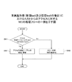
図14は、本実施形態(物理IaaSの場合)における管理サーバによる物理サーバへのリソースの割当処理のフローの一例を示す。本実施形態では、ユーザに提供する物理リソース(サーバ、ネットワーク等)は予め決定されているものとする。 FIG. 14 shows an example of the flow of resource allocation processing to the physical server by the management server in this embodiment (in the case of physical IaaS). In the present embodiment, it is assumed that physical resources (server, network, etc.) provided to the user are determined in advance.
管理サーバ14は、物理リソース割当テーブル54から1レコードを読み出す。管理サーバ14は、その読み出したレコードの「ネットワーク」54−6をキーとして、ネットワーク割当テーブル55から「VLAN ID」55−2に格納されたタグ値(VLAN ID)を取得する(S1)。
The
次に、管理サーバ14は、読み出したレコードの「配備先サーバ名」54−4をキーとして、管理ボード情報テーブル56から、その配備先サーバ名に対応する管理ボード情報(管理ボード IP、ユーザID、パスワード)を取得する(S2)。
Next, the
管理サーバ14は、その取得した管理ボード情報の管理ボード IPに対応する管理ボード13に接続し、ユーザID及びパスワードをその管理ボード13に送信する。管理ボード13は、予め自身に登録されたユーザID及びパスワードを用いて、送信されたユーザID及びパスワードに対する認証を行う(S3)。
The
管理ボード13による認証後、管理サーバ14は、管理ボード13を介して、物理サーバ11に搭載されたNIC12のNIC設定情報26を削除する指示を行う(S4)。NIC12では、その指示情報に基づいて、管理ボード側管理I/F24は、記憶部25からNIC設定情報26を削除(初期化)する。
After authentication by the
管理サーバ14は、管理ボード13を介して、その管理ボード13を有する物理サーバ11のNIC12に、S1で取得したタグ値、物理リソース割当テーブル54から取得したMACアドレス等、後述するNIC設定情報26の各設定項目を含む設定情報を送信する(S5)。NIC12において、管理ボード側管理I/F24は、その設定情報を受信すると、その設定情報に基づいて、NIC設定情報26の設定を行う。具体的には、管理ボード側管理I/F24は、NIC設定情報26の「タグ値」26−3及び「受信マスク」26−4について、取得したタグ値に対応する「受信マスク」26−4のマスクを無効(○)にし、それ以外のタグ値についてマスクを有効(×)に設定する。また、管理ボード側管理I/F24は、「ホスト経由cfg」26−1に「無効」を設定する。管理ボード側管理I/F24は、「受信フィルタ」26−2に「有効」を設定する。管理ボード側管理I/F24は、「タグ無し受信」26−5に「無効」を設定する。管理ボード側管理I/F24は、「受信タグ削除」26−6に「有効」を設定する。管理ボード側管理I/F24は、「送信タグ埋め込み」26−7に「有効」を設定する。管理ボード側管理I/F24は、「送信タグ値」26−8に取得したタグ値(VLAN ID)を設定する。管理ボード側管理I/F24は、「割当MACアドレス」26−9に、物理リソース割当テーブル54から取得された「MACアドレス」54−5を設定する。管理ボード側管理I/F24は、「プロミスキャスモード」26−10に「無効」を設定する。
The
リソースを割り当てる物理サーバ11数分、管理サーバ14は、S1〜S5の処理を繰り返す。リソースを割り当てる全物理サーバ11について、S1〜S5の処理が終了した場合、管理サーバ14は、次の処理を行う。すなわち、管理サーバ14は、管理ボード13を介して、その物理サーバ11毎に、OS及びミドルウェア等のユーザのためのシステムの導入等の制御を行い(S6)、その物理サーバ11を起動する(S7)。
The
図15は、本実施形態(物理IaaSの場合)における管理サーバによる物理サーバのリソースの割当の解除処理のフローの一例を示す。管理サーバ14は、管理ボード13を介して、各物理サーバ11のOS及びミドルウェア等のユーザのシステムの削除等の制御を行い(S11)、物理サーバ11を停止させる(S12)。
FIG. 15 shows an example of the flow of the physical server resource deallocating process by the management server in the present embodiment (in the case of physical IaaS). The
管理サーバ14は、物理リソース割当テーブル54から1レコードを読み出す。管理サーバ14は、読み出したレコードの「配備先サーバ名」54−4をキーとして、管理ボード情報テーブル56から、その配備先サーバ名に対応する管理ボード情報(管理ボードIP、ユーザ名、パスワード)を取得する(S13)。
The
管理サーバ14は、管理ネットワーク15を介して、その取得した管理ボード情報の管理ボード IPに対応する管理ボード17に接続し、ユーザ名及びパスワードをその管理ボード13に送信する。管理ボード13は、予め自身に登録されたユーザ名及びパスワードを用いて、送信されたユーザ名及びパスワードに対する認証を行う(S14)。
The
管理ボード13による認証後、管理サーバ14は、管理ボード13を介して、物理サーバ11に搭載されたNIC12のNIC設定情報26を削除する指示を行う(S15)。NIC12では、その指示情報に基づいて、管理ボード側管理I/F24は、記憶部25からNIC設定情報26を削除(初期化)する。
After authentication by the
リソースの割り当てを解除する物理サーバ11数分、管理サーバ14は、S13〜S15の処理を繰り返す。
The
図16は、本実施形態(物理IaaSの場合)のテナント毎のVLANの運用の一実施例を示す。図13で説明したように、物理サーバ1(11−1)及び物理サーバ2(11−2)には、テナントAが割り当てられている。また、物理サーバ1(11−1)及び物理サーバ2(11−2)のNIC設定情報26には、VLANのタグ値=「1001」が設定されている。
FIG. 16 shows an example of VLAN operation for each tenant in the present embodiment (in the case of physical IaaS). As described in FIG. 13, the tenant A is allocated to the physical server 1 (11-1) and the physical server 2 (11-2). Further, the VLAN tag value = “1001” is set in the
また、物理サーバ3(11−3)、物理サーバ4(11−4)及び物理サーバ5(11−2)には、テナントBが割り当てられている。また、物理サーバ3(11−3)、物理サーバ4(11−4)及び物理サーバ5(11−2)のNIC設定情報26には、VLANのタグ値=「1011」が設定されている。
Also, tenant B is assigned to physical server 3 (11-3), physical server 4 (11-4), and physical server 5 (11-2). Also, the VLAN tag value = “1011” is set in the
例えば、物理サーバ3(11−3)が、テナントB内の他の物理サーバにデータを送信するとする。このとき、物理サーバ3(11−3)のNIC12は、送信するフレームにVLANタグを埋め込んで、運用ネットワーク16に送信する。VLANタグが埋め込まれたフレームは、運用ネットワーク16を介して、物理サーバ1(11−1)、物理サーバ2(11−2)、物理サーバ4(11−4)、及び物理サーバ5(11−5)の各NIC12に到達する。
For example, it is assumed that the physical server 3 (11-3) transmits data to another physical server in the tenant B. At this time, the
この場合、物理サーバ4(11−4)及び物理サーバ5(11−5)のNIC12は、受信したフレームのVLANタグのタグ値が、自身のNIC設定情報26に設定されたタグ値と一致すると判定する。すると、物理サーバ4(11−4)及び物理サーバ5(11−5)のNIC12は、受信したフレームからVLANタグを取り除き、VLANタグを取り除いたフレームをホスト側へ転送する。
In this case, if the
一方、物理サーバ1(11−1)及び物理サーバ2(11−2)のNIC12は、受信したVLANタグフレームのVLANタグのタグ値が、自身に設定されたタグ値と一致しないから、そのフレームを破棄する。
On the other hand, the
図17は、本実施形態(物理IaaSの場合)におけるホスト−管理ボード−NIC間のコマンドシーケンスの一例を示す。物理IaaSの運用準備段階において、(1)NIC12の設定初期化を行う場合、管理サーバ14の指示に基づいて、管理ボード13は、NIC12に対し、NIC設定情報26の初期化を指示する。NIC12は、その指示に基づいて、NIC設定情報26の初期化を行う。初期化が完了すると、NIC12は、初期化の完了を管理ボード13に通知する。
FIG. 17 shows an example of a command sequence between the host, the management board, and the NIC in this embodiment (in the case of physical IaaS). In the physical IaaS operation preparation stage, (1) when the setting initialization of the
物理IaaSの運用準備段階において、(2)ホストによるNIC12へのアクセスを禁止する場合、管理サーバ14の指示に基づいて、管理ボード13はNIC12に対し、NIC設定情報26の「ホスト経由cfg」26−1を「無効」にするように指示する。NIC12は、その指示に基づいて、NIC設定情報26の「ホスト経由cfg」26−1に「無効」を設定する。NIC設定情報26の更新が完了すると、NIC12は、NIC設定情報26の更新の完了を管理ボード13に通知する。
In the operation preparation stage of physical IaaS, (2) when prohibiting access to the
物理IaaSの運用準備段階において、(3)VLANの設定を行う場合、管理サーバ14の指示に基づいて、管理ボード13はNIC12に対し、管理サーバ14から指定されたタグ値を、NIC設定情報26に設定するように指示する。NIC12は、その指示に基づいて、管理サーバ14から指定されたタグ値に対応する「タグ値」26−3の「受信マスク」26−4を無効状態(○)に設定する。VLANタグの設定が完了すると、NIC12は、VLANタグの設定の完了を管理ボード13に通知する。
In the physical IaaS operation preparation stage, (3) when setting a VLAN, based on an instruction from the
物理IaaSの運用段階において、(4)ホストは、ホストに許可されている制御コマンドについて、NIC12に制御コマンドを送信する。NIC12は、その制御コマンドに基づいて、処理を実行する。処理が完了すると、NIC12は、処理の完了をホストに通知する。
In the physical IaaS operation stage, (4) the host transmits a control command to the
物理IaaSの撤収段階において、(5)NIC12の設定初期化を行う場合、管理サーバ14の指示に基づいて、管理ボード13は、NIC12に対し、NIC設定情報26の初期化を指示する。NIC12は、その指示に基づいて、NIC設定情報26の初期化を行う。初期化が完了すると、NIC12は、初期化の完了を管理ボード13に通知する。
In the physical IaaS withdrawal stage, (5) when setting initialization of the
図18は、本実施形態(物理IaaSの場合)におけるホスト−ホスト間のフレームシーケンスの一例を示す。ホストA1は、NIC A1に、フレームを転送する。NIC A1は、ホストA1から転送されたフレームのヘッダに、VLANタグを埋め込む。NIC A1は、そのVLANタグを埋め込んだフレームを物理ネットワークへ転送する。 FIG. 18 shows an example of a host-host frame sequence in the present embodiment (in the case of physical IaaS). Host A1 transfers the frame to NIC A1. The NIC A1 embeds a VLAN tag in the header of the frame transferred from the host A1. NIC A1 transfers the frame in which the VLAN tag is embedded to the physical network.
NIC A2は、物理ネットワークを介して送信されたフレームを受信する。NIC A2は、受信したフレームのVLANタグのタグ値が、自身に設定されたタグ値と一致するか否かを判定する。受信したフレームのVLANタグのタグ値が、自身に設定されたタグ値と一致する場合、NIC A2は、受信したフレームからVLANタグを取り除き、VLANタグを取り除いたフレームをホストB2側へ転送する。 The NIC A2 receives the frame transmitted via the physical network. The NIC A2 determines whether or not the tag value of the VLAN tag of the received frame matches the tag value set for itself. When the tag value of the VLAN tag of the received frame matches the tag value set for itself, NIC A2 removes the VLAN tag from the received frame and transfers the frame from which the VLAN tag has been removed to the host B2 side.
<仮想IaaSの場合>
次に、仮想IaaSについての例について説明する。なお、物理IaaS環境において、既に説明した構成、処理、または機能と同じものについては、同一の符号を付し、その説明を省略する。
<For virtual IaaS>
Next, an example of virtual IaaS will be described. In the physical IaaS environment, the same components, processes, or functions as those already described are denoted by the same reference numerals and description thereof is omitted.
図19は、本実施形態(仮想IaaSの場合)における物理サーバの一例を示す。物理サーバ11は、NIC12、管理ボード13、ホスト環境81を含む。
FIG. 19 shows an example of a physical server in the present embodiment (in the case of virtual IaaS). The
物理サーバ11のホスト環境81は、仮想化技術により仮想化された環境である。ホスト環境81では、複数の仮想計算機(VM:Virtual Machine)が動作する。したがって、仮想化技術により、各VM(ゲスト環境)82でオペレーティングシステム(OS)を稼動させることができる。これにより、各ゲスト環境82(82−1、82−2)で、VMが動作する。
The
VM/VMM制御部83は、VMを生成すると共に、VM生成時のVMMの動作を制御する。また、VM/VMM制御部83は、VMについてのVLAN環境を構築する。このとき、VM/VMM制御部83は、VMについてのVLAN環境を管理するためのVM-VLANタグ関係テーブルを作成する。VMM85は、生成されたVMの動作を制御する。
The VM /
NIC制御部84は、VM間のネットワークの接続を切り替える仮想スイッチ機能を有する。NIC制御部84は、VM-VLANタグ関係テーブル86に基づいて、VLANタグに応じてフレームをVMへルーティングする機能を有する。また、NIC制御部84は、VLANタグの埋め込み及び削除等を行う機能を有する。
The
NIC12、管理ボード13については、物理IaaS環境において、既に説明したものと同様である。なお、NIC設定情報26については、各VMに対応する「タグ値」26−3の「受信マスク」26−4のマスクが無効(×)になっている。また、ホスト側管理I/F23は、NIC12に関する制御に関して、ホスト(VMM)と通信するための通信インターフェースである。ホスト側管理I/F23は、アクセス制御テーブル27に基づいて、ホスト(VMM)からのアクセスを制御する。
The
図20は、本実施形態(仮想IaaSの場合)における管理サーバの一例を示す。管理サーバ14は、リソース管理部51、NIC制御部52、格納部53を含む。リソース管理部51、NIC制御部52については、物理IaaS環境において、既に説明したものと同様である。
FIG. 20 shows an example of a management server in the present embodiment (in the case of virtual IaaS). The
格納部53には、物理リソース割当テーブル54a、ネットワーク割当テーブル55a、管理ボード情報テーブル56a、仮想リソース割当テーブル91、VMM IPテーブル92が格納されている。
The
図21は、本実施形態(仮想IaaSの場合)における物理リソース割当テーブルの一例を示す。物理リソース割当テーブル54aに含まれるデータ項目は、図8と同じであるので、その説明を省略する。 FIG. 21 shows an example of a physical resource allocation table in the present embodiment (in the case of virtual IaaS). Since the data items included in the physical resource allocation table 54a are the same as those in FIG. 8, the description thereof is omitted.
物理リソース割当テーブル54aでは、「テナント」54−1には、センタ名が格納されている。「サービス」54−2には、ホスト環境81を構築する物理サーバ11がVMのホストであることを示す「VMHOST」が格納されている。また、「MACアドレス」54−4には、配備先の物理サーバ11に搭載されているNICの実MACアドレスが格納されている。
In the physical resource allocation table 54a, the “tenant” 54-1 stores the center name. “Service” 54-2 stores “VMHOST” indicating that the
なお、物理リソース割当テーブル54aに、物理IaaSで用いる物理リソース割当テーブル54の内容が混在していてもよい。 The contents of the physical resource allocation table 54 used in the physical IaaS may be mixed in the physical resource allocation table 54a.
図22は、本実施形態(仮想IaaSの場合)におけるネットワーク割当テーブルの一例を示す。ネットワーク割当テーブル55aに含まれるデータ項目は、図9と同じであるので、その説明を省略する。 FIG. 22 shows an example of a network allocation table in the present embodiment (in the case of virtual IaaS). Since the data items included in the network allocation table 55a are the same as those in FIG. 9, the description thereof is omitted.
なお、ネットワーク割当テーブル55aに、物理IaaSで用いるネットワーク割当テーブル55の内容が混在していてもよい。 The contents of the network allocation table 55 used in the physical IaaS may be mixed in the network allocation table 55a.
図23は、本実施形態(仮想IaaSの場合)における管理ボード情報テーブルの一例を示す。管理ボード情報テーブル56aに含まれるデータ項目は、図10と同じであるので、その説明を省略する。なお、「サーバ」56−1には、物理サーバ11のサーバ名が格納されている。
FIG. 23 shows an example of a management board information table in the present embodiment (in the case of virtual IaaS). The data items included in the management board information table 56a are the same as those in FIG. The “server” 56-1 stores the server name of the
なお、管理ボード情報テーブル56aに、物理IaaSで用いる管理ボード情報テーブル56の内容が混在していてもよい。 The contents of the management board information table 56 used in the physical IaaS may be mixed in the management board information table 56a.
図24は、本実施形態(仮想IaaSの場合)における仮想リソース割当テーブルの一例を示す。仮想リソース割当テーブル91は、「テナント」91−1、「サービス」91−2、「サーバ名」91−3、「サーバID」91−4、「MACアドレス」91−5、「ネットワーク」91−6のデータ項目を含む。 FIG. 24 shows an example of a virtual resource allocation table in the present embodiment (in the case of virtual IaaS). The virtual resource allocation table 91 includes “tenant” 91-1, “service” 91-2, “server name” 91-3, “server ID” 91-4, “MAC address” 91-5, “network” 91-. Contains 6 data items.
「テナント」には、テナント名が格納される。「サービス」91−2には、テナントで利用しているサービス名が格納される。「サーバ名」91−3には、そのテナントで利用するVM82を識別する情報が格納されている。「配備先サーバ名」91−4には、そのVM82を構築している物理サーバ11を識別する情報が格納される。「MACアドレス」91−5には、VM82に割り当てられたMACアドレスが格納される。「ネットワーク」91−6には、そのVM82が属するテナントを形成するネットワーク(VLAN)の名称が格納される。
"Tenant" stores the tenant name. “Service” 91-2 stores the name of the service used by the tenant. The “server name” 91-3 stores information for identifying the
図25は、本実施形態(仮想IaaSの場合)におけるVMM IPテーブルの一例を示す。VMM IPテーブル92は、「サーバ」92−1、「VMM IP」92−2のデータ項目を含む。 FIG. 25 shows an example of a VMM IP table in the present embodiment (in the case of virtual IaaS). The VMM IP table 92 includes data items of “server” 92-1 and “VMM IP” 92-2.
「サーバ」92−1には、そのVM82を構築している物理サーバ11を識別する情報が格納される。「VMM制御IP」92−2には、その物理サーバ11に導入されているVMMを制御するためのIP(Internet Protocol)アドレスが格納される。
The “server” 92-1 stores information for identifying the
図26は、本実施形態(仮想IaaSの場合)におけるVM−VLAN ID関係テーブルの一例を示す。VM−VLAN ID関係テーブル86は、VMについてのVLANを構築する場合に作成されるテーブルである。VM−VLAN ID関係テーブル86は、「仮想NICのMACアドレス」86−1、「VLAN ID」86−2のデータ項目を含む。 FIG. 26 shows an example of a VM-VLAN ID relationship table in the present embodiment (in the case of virtual IaaS). The VM-VLAN ID relationship table 86 is a table created when a VLAN for a VM is constructed. The VM-VLAN ID relationship table 86 includes data items of “Virtual NIC MAC address” 86-1 and “VLAN ID” 86-2.
「仮想NICのMACアドレス」86−1には、送信先の仮想サーバ(VM)の仮想NICのMACアドレスが格納される。「VLAN ID」86−2には、そのVMで使用するVLANを識別するVLAN ID(タグ値)が格納される。 The “virtual NIC MAC address” 86-1 stores the MAC address of the virtual NIC of the destination virtual server (VM). The “VLAN ID” 86-2 stores a VLAN ID (tag value) for identifying a VLAN used in the VM.
次に、仮想IaaSについて、より詳細な実施例を用いて説明する。
図27は、本実施形態(仮想IaaSの場合)におけるテナント毎の物理リソース及び仮想リソースの割り当ての一実施例を示す。図27の仮想IaaSでは、物理サーバ6〜8(11−6〜11−8)、管理サーバ14、ポータルサーバ71、端末A(72)、端末B(73)がある。物理サーバ6〜8(11−6〜11−8)は、NIC12を介して、運用ネットワーク16と接続されている。物理サーバ6〜8(11−6〜11−8)は、管理ボード13を介して、管理ネットワーク15と接続されている。管理サーバ14は、管理ネットワーク15及び運用ネットワーク16と接続されている。管理サーバ14は、ポータルサーバ71と接続されている。
Next, virtual IaaS will be described using a more detailed example.
FIG. 27 shows an example of allocation of physical resources and virtual resources for each tenant in the present embodiment (in the case of virtual IaaS). In the virtual IaaS of FIG. 27, there are
ポータルサーバ71は、テナント管理者用のネットワーク74を介して、端末A(72)、端末B(73)と接続されている。端末A(72)は、テナントAの管理者が使用する情報処理端末である。端末B(73)は、テナントBの管理者が使用する情報処理端末である。ポータルサーバ71は、物理IaaSのポータルサーバである。テナントの管理者は各端末72,73を使用して、ポータルサーバ71を介して、対象となる物理サーバ11にリソースを割り当てる。
The
たとえば、テナントAの管理者は、端末A(72)を用いて、物理サーバ6(11−6)にテナントC1を、物理サーバ7(11−7)にテナントC2を割り当てる指示を行う。 For example, the administrator of tenant A uses terminal A (72) to give an instruction to assign tenant C1 to physical server 6 (11-6) and tenant C2 to physical server 7 (11-7).
すると、管理サーバ14のNIC制御部52は、管理ネットワーク15及び管理ボード13を介して、物理サーバ7(11−7)及び物理サーバ7(11−7)に、VMMを導入する。これにより、物理サーバ6〜8(11−6〜11−8)に、ホスト環境(VMM)81が構築される。このとき、管理サーバ14は、管理ネットワーク15及び管理ボード13を介して、物理サーバ6〜8(11−6〜11−8)のNIC設定情報26の「ホスト経由cfg」26−1を「有効」に設定する(S21)。
Then, the
次に、運用ネットワーク16を介した管理サーバ14からの指示に基づいて、VM/VMM制御部83は、NIC12にVLANタグ=「1002」を設定する(S22)。運用ネットワーク16を介した管理サーバ14からの指示に基づいて、VM/VMM制御部83は、VMを導入して、そのVMにテナントを割り当てる。運用ネットワーク16を介した管理サーバ14からの指示に基づいて、VM/VMM制御部83は、VMと、そのVMに対応するVLANとのパスを設定する(S23)。
Next, based on an instruction from the
テナントBについても、テナントAと同様にして、物理サーバ11にVMMを導入し、NIC設定情報26の情報を設定し、VMと、そのVMに対応するVLANとのパスを設定する(S21〜S23)。
Similarly to tenant A, tenant B installs VMM in
図28は、本実施形態(仮想IaaSの場合)における管理サーバによる物理サーバへのリソースの割当処理のフローの一例を示す。本実施形態では、ユーザに提供する物理リソース(物理サーバ、ネットワーク等)及び仮想リソース(VMM)は予め決定されているものとする。 FIG. 28 shows an example of a flow of resource allocation processing to a physical server by the management server in this embodiment (in the case of virtual IaaS). In the present embodiment, it is assumed that physical resources (physical servers, networks, etc.) and virtual resources (VMM) provided to the user are determined in advance.
管理サーバ14は、物理リソース割当テーブル54aから1レコードを読み出す。管理サーバ14は、読み出したレコードの「配備先サーバ名」54−4をキーとして、管理ボード情報テーブル56aから、その配備先サーバ名に対応する管理ボード情報(管理ボード IP、ユーザID、パスワード)を取得する(S31)。
The
管理サーバ14は、その取得した管理ボード情報の管理ボード IPに対応する管理ボード13に接続し、ユーザID及びパスワードをその管理ボード13に送信する。管理ボード13は、予め自身に登録されたユーザID及びパスワードを用いて、送信されたユーザID及びパスワードに対する認証を行う(S32)。
The
管理ボード13による認証後、管理サーバ14は、管理ボード13を介して、その管理ボード13を有する物理サーバ11に搭載されたNIC12のNIC設定情報26を削除する(初期化)(S33)。
After authentication by the
管理サーバ14は、管理サーバ14は、管理ボード13を介して、その管理ボード13を有する物理サーバ11のNIC12に、後述するNIC設定情報26の各設定項目を含む設定情報を送信する。NIC12において、管理ボード側管理I/F24は、その設定情報を受信すると、その設定情報に基づいて、NIC設定情報26の設定を行う。具体的には、管理ボード側管理I/F24は、NIC12のNIC設定情報26の「ホスト経由cfg」を「有効」に設定する(S34)。また、管理ボード側管理I/F24は、「受信フィルタ」26−2に「有効」を設定する。管理ボード側管理I/F24は、「タグ無し受信」26−5に「有効」を設定する。管理ボード側管理I/F24は、「受信タグ削除」26−6に「無効」を設定する。管理ボード側管理I/F24は、「送信タグ埋め込み」26−7に「無効」を設定する。管理ボード側管理I/F24は、「割当MACアドレス」26−9に、「MACアドレス」29−11の値を設定する。管理サーバ14は、「プロミスキャスモード」26−10に「無効」を設定する。
The
管理サーバ14は、管理ボード13を介して、VMM等を物理サーバ11に導入し(S35)、VMMを起動させる(S36)。
The
リソースを割り当てる物理サーバ11数分、管理サーバ14は、S31〜S36の処理を繰り返す。
The
図29は、本実施形態(仮想IaaSの場合)における管理サーバによる物理サーバのリソースの割当の解除処理のフローの一例を示す。管理サーバ14は、管理ボード13を介して、各物理サーバ11のVMM等の削除等の制御を行い(S41)、物理サーバ11を停止させる(S42)。
FIG. 29 shows an example of the flow of the physical server resource deallocating process by the management server in this embodiment (in the case of virtual IaaS). The
管理サーバ14は、物理リソース割当テーブル54から1レコードを読み出す。管理サーバ14は、その読み出したレコードの「配備先サーバ名」54−4をキーとして、管理ボード情報テーブル56aから、その配備先サーバ名に対応する管理ボード情報(管理ボードIP、ユーザ名、パスワード)を取得する(S43)。
The
管理サーバ14は、その取得した管理ボード情報の管理ボード IPに対応する管理ボード17に接続し、ユーザ名及びパスワードをその管理ボード13に送信する。管理ボード13は、予め自身に登録されたユーザ名及びパスワードを用いて、送信されたユーザ名及びパスワードに対する認証を行う(S44)。
The
管理ボード13による認証後、管理サーバ14は、管理ボード13を介して、物理サーバ11に搭載されたNIC12のNIC設定情報26を削除する指示を行う(S45)。NIC12では、その指示情報に基づいて、管理ボード側管理I/F24は、記憶部25からNIC設定情報26を削除(初期化)する。
After authentication by the
リソースの割り当てを解除する物理サーバ11数分、管理サーバ14は、S41〜S45の処理を繰り返す。
The
図30は、本実施形態(仮想IaaSの場合)における管理サーバによる物理サーバへのVMの割当処理のフローの一例を示す。本実施形態では、ユーザに提供するVMに関するリソースは予め決定されているものとする。 FIG. 30 shows an example of the flow of a process for assigning a VM to a physical server by the management server in this embodiment (in the case of virtual IaaS). In this embodiment, it is assumed that the resources related to the VM provided to the user are determined in advance.
管理サーバ14は、仮想リソース割当テーブル91から1レコードを読み出す。管理サーバ14は、読み出したレコードの「配備先サーバ名」91−4をキーとして、VMM IPテーブル92から、その配備先サーバ名に対応するVMM IPを取得する(S51)。さらに、管理サーバ14は、仮想リソース割当テーブル91から読み出したレコードの「ネットワーク」91−6をキーとして、ネットワーク割当テーブル55aから、そのネットワーク名に対応するVLAN ID(タグ値)を取得する。
The
管理サーバ14は、仮想リソース割当テーブル91から読み出したレコードの配備先サーバ名」91−4と「ネットワーク」91−6を用いて、既に、その物理サーバに同一のVLANが存在するかを判定する(S52)。なお、管理サーバ14は、取得したVMM IPのVMMに、仮想リソース割当テーブル91から読み出したレコードの「ネットワーク」91−6と同一のVLANが存在するかの問い合わせを行ってもよい。
The
その物理サーバに同一のVLANが存在しない場合(S52で「No」)、管理サーバ14は、次の処理を行う。管理サーバ14は、S51で取得したVMM IPのVMMに対して、NIC12にその取得したVLANタグ値を設定するように指示する。その指示に基づいて、VM/VMM制御部83は、NIC設定情報26について、管理サーバ14から送信されたVLANタグ値に対応する「タグ値」26−3の「受信マスク」26−4を「○」に設定する(S53)。
When the same VLAN does not exist in the physical server (“No” in S52), the
その物理サーバ11に同一のVLANが存在しない場合(S52で「Yes」)、管理サーバ14は、S51で取得したVMM IP宛に、VLANタグ値を送信する。
When the same VLAN does not exist in the physical server 11 (“Yes” in S52), the
VM/VMM制御部83は、これから配備しようとするVMのVLANを指定する(S54)。すなわち、VM/VMM制御部83は、これから配備しようとするVMの仮想NICのMACアドレスと、VLAN IDとを関係づけた情報を、VM−VLAN ID関係テーブル86に格納する。
The VM /
管理サーバ14は、VMM IPを用いて、そのVMMにVMの配備を指示する。すると、VMMは、VMの配備を行う(S55)。このとき、VMMは、VMとそのVMに対応するVLANとのパスを設定する。その後、VMは起動する(S56)。
The
リソースを割り当てるVM数分、管理サーバ14及びVMMは、S51〜S56の処理を繰り返す。
The
図31は、本実施形態(仮想IaaSの場合)における管理サーバによるVMの割当の解除処理のフローの一例を示す。管理サーバ14は、仮想リソース割当テーブル91から1レコードを読み出す。管理サーバ14は、読み出したレコードの「配備先サーバ名」91−4をキーとして、VMM IPテーブル92から、その配備先サーバ名に対応するVMM IPを取得する(S61)。
FIG. 31 shows an example of the flow of the VM allocation release processing by the management server in this embodiment (in the case of virtual IaaS). The
管理サーバ14は、運用ネットワーク16を介して、VMM IPを用いて、そのVMMに、VMの動作を停止するように指示をする。その指示に基づいて、VMMは、そのVMを停止させる(S62)。
The
管理サーバ14は、運用ネットワーク16を介して、そのVMMに、VMをVLANから切り離すように指示をする。その指示に基づいて、VMMは、VM−VLAN ID関係テーブル86から、そのVMの仮想NICのMACアドレスと、VLAN IDとの関係情報を削除する(S63)。
The
VMMのVM/VMM制御部83は、そのVLANタグ値で示されるVLANを使用しているVMが他にないか否かを判定する(S64)。そのVLANタグ値で示されるVLAN を使用しているVMが他にない場合(S64で「Yes」)、VM/VMM制御部83は、次の処理を行う。すなわち、VM/VMM制御部83は、NIC12のNIC設定情報26において、その削除したVLANタグ値に対応する「タグ値」26−3の「受信マスク」26−4に「×」を設定する(S65)。
The VM /
図32は、本実施形態(仮想IaaSの場合)におけるホスト−管理ボード−NIC間のコマンドシーケンスの一例を示す。仮想IaaSの運用準備段階において、(1)NICの設定初期化を行う場合、管理サーバ14の指示に基づいて、管理ボード13は、NIC12に対し、NIC設定情報26の初期化を指示する。NIC12は、その指示に基づいて、NIC設定情報26の初期化を行う。初期化が完了すると、NIC12は、初期化の完了を管理ボード13に通知する。
FIG. 32 shows an example of a command sequence between the host, the management board, and the NIC in the present embodiment (in the case of virtual IaaS). In the virtual IaaS operation preparation stage, (1) when performing NIC setting initialization, the
仮想IaaSの運用準備段階において、(2)ホスト(VMM)によるNIC12の制御を許可する場合、管理サーバ14の指示に基づいて、管理ボード13はNIC12に対し、NIC設定情報26の「ホスト経由cfg」26−1を「有効」にするように指示する。NIC12は、その指示に基づいて、NIC設定情報26の「ホスト経由cfg」26−1に「有効」を設定する。NIC設定情報26の更新が完了すると、NIC12は、NIC設定情報26の更新の完了を管理ボード13に通知する。
In the operation preparation stage of virtual IaaS, (2) when the control of the
仮想IaaSの運用段階において、(3)VLANの設定を行う場合、ホスト(VMM)はNIC12に対し、管理サーバ14から指定されたタグ値を、NIC設定情報26に設定するように指示する。NIC12は、その指示に基づいて、ホスト(VMM)から指定されたタグ値に対応する「タグ値」26−3の「受信マスク」26−4を「○」にする。VLANタグの設定が完了すると、NIC12は、VLANタグの設定の完了をホスト(VMM)に通知する。
In the virtual IaaS operation stage, (3) when setting the VLAN, the host (VMM) instructs the
仮想IaaSの運用段階において、(4)VLANの追加を行う場合、ホスト(VMM)はNIC12に対し、管理サーバ14から指定されたタグ値を、NIC設定情報26に設定するように指示する。NIC12は、その指示に基づいて、ホスト(VMM)から指定されたタグ値に対応する「タグ値」26−3の「受信マスク」26−4を「○」にする。VLANタグの追加が完了すると、NIC12は、VLANタグの追加の完了をホスト(VMM)に通知する。
In the virtual IaaS operation stage, (4) when adding a VLAN, the host (VMM) instructs the
仮想IaaSの運用段階において、(5)VLANの削除、すなわちVLANからVMを切り離す場合、ホスト(VMM)はNIC12に対し、そのVLANを削除するように指示する。NIC12は、その指示に基づいて、ホスト(VMM)から指定されたタグ値に対応する「タグ値」26−3の「受信マスク」26−4を「×」にする。VLANタグの削除が完了すると、NIC12は、VLANタグの削除の完了をホスト(VMM)に通知する。
In the virtual IaaS operation stage, (5) when deleting a VLAN, that is, when separating a VM from a VLAN, the host (VMM) instructs the
仮想IaaSの撤収段階において、(6)ホストによるNIC12の制御を禁止する場合、管理サーバ14の指示に基づいて、管理ボード13はNIC12に対し、NIC設定情報26の「ホスト経由cfg」26−1を「無効」にするように指示する。NIC12は、その指示に基づいて、NIC設定情報26の「ホスト経由cfg」26−1に「無効」を設定する。NIC設定情報26の更新が完了すると、NIC12は、NIC設定情報26の更新の完了を管理ボード13に通知する。
In the virtual IaaS withdrawal stage, (6) when the control of the
仮想IaaSの撤収段階において、(7)NICの設定初期化を行う場合、管理サーバ14の指示に基づいて、管理ボード13は、NIC12に対し、NIC設定情報26の初期化を指示する。NIC12は、その指示に基づいて、NIC設定情報26の初期化を行う。初期化が完了すると、NIC12は、初期化の完了を管理ボード13に通知する。
In the virtual IaaS withdrawal stage, when performing (7) NIC setting initialization, the
図33は、本実施形態(仮想IaaSの場合)におけるゲストOS−ゲストOS間フレームシーケンス及びVMM−管理サーバ間のフレームシーケンスの一例を示す。 FIG. 33 shows an example of a guest OS-guest OS frame sequence and a VMM-management server frame sequence in the present embodiment (in the case of virtual IaaS).
まずは、ゲストOS−ゲストOS間フレームシーケンスについて説明する。ゲストOS Xは、ホストX(VMM)に、データを転送する。ホストX(VMM)は、ゲストOS Xから転送されたデータのフレームヘッダに、VLANタグを埋め込む。ホストX(VMM X)は、そのVLANタグを埋め込んだフレームをNIC Xを介して、物理ネットワークへ転送する。 First, the guest OS-guest OS frame sequence will be described. Guest OS X transfers data to host X (VMM). The host X (VMM) embeds a VLAN tag in the frame header of the data transferred from the guest OS X. Host X (VMM X) transfers the frame in which the VLAN tag is embedded to the physical network via NIC X.
NIC Yは、物理ネットワークを介して送信されたフレームを受信する。NIC Yは、そのフレームをホストY(VMM Y)へ転送する。ホストY(VMM Y)は、そのフレームのVLANタグのタグ値が、VM−VLAN ID関係テーブル86に登録されているかを判定する。そのフレームのVLANタグのタグ値が、VM−VLAN ID関係テーブル86に登録されている場合、ホストY(VMM Y)は、そのフレームからVLANタグを削除する。それから、ホストY(VMM Y)は、VM−VLAN ID関係テーブル86を用いて、そのVLANタグ値に対応する仮想NICのMACアドレスで示されるVM(ゲストOS)へ、そのVLANタグが削除されたフレームを転送する。 NIC Y receives the frame transmitted via the physical network. NIC Y transfers the frame to host Y (VMM Y). The host Y (VMM Y) determines whether the tag value of the VLAN tag of the frame is registered in the VM-VLAN ID relationship table 86. When the tag value of the VLAN tag of the frame is registered in the VM-VLAN ID relation table 86, the host Y (VMM Y) deletes the VLAN tag from the frame. Then, the host Y (VMM Y) uses the VM-VLAN ID relation table 86 to delete the VLAN tag to the VM (guest OS) indicated by the MAC address of the virtual NIC corresponding to the VLAN tag value. Forward the frame.
次に、VMM−管理サーバ間のフレームシーケンスについて説明する。VMMは、管理サーバ14宛てにデータを含むフレームを送信する。NIC Xは、VMMからのフレームを物理ネットワークへ転送する。管理サーバ14は、物理ネットワークを介して送信されたフレームを受信する。
Next, a frame sequence between the VMM and the management server will be described. The VMM transmits a frame including data to the
<物理IaaS及び仮想IaaSに共通する処理>
次に、物理IaaS及び仮想IaaSにおいて用いる共通の処理について説明する。
<Processing common to physical IaaS and virtual IaaS>
Next, common processing used in physical IaaS and virtual IaaS will be described.
図34は、本実施形態(物理IaaS及び仮想IaaSの場合)における管理ボードからのアクセスに対するNICの処理フローの一例を示す。管理ボード13のNIC用管理部28は、管理ボード側管理I/F16を介して、NIC12が有するアクセス制御テーブル27へのアクセスを試みるとする。
FIG. 34 shows an example of the NIC processing flow for access from the management board in this embodiment (in the case of physical IaaS and virtual IaaS). Assume that the
NIC用管理部28からのアクセスがあると、NIC12の管理ボード側管理I/F24は、アクセス制御テーブル27を参照し、NIC設定情報26の各設定項目へのアクセスが許可されているか否かを判定する(S71)。アクセス制御テーブル27へのアクセスが禁止されている場合(S71で「No」)、管理ボード側管理I/F24は、NIC用管理部28へエラー応答を返信する(S72)。
When there is an access from the
アクセス制御テーブル27へのアクセスが許可されている場合(S71で「Yes」)、管理ボード側管理I/F24は、次の処理を行う。すなわち、管理ボード側管理I/F24は、アクセス制御テーブル27に設定されたアクセス制限(NIC設定情報26に含まれる各設定項目に対するアクセス制限)に応じて、NIC設定情報26に含まれる各設定項目の読み取り、または更新を行う(S73)。
When access to the access control table 27 is permitted (“Yes” in S71), the management board side management I /
NIC設定情報26の更新の結果、「ホスト経由cfg」26−1の設定内容に変更がある場合(S74で「Yes」)、管理ボード側管理I/F24は、アクセス制御テーブル27のアクセス制限の切替を行う(S75)。例えば、「ホスト経由cfg」26−1が「無効」に更新されている場合、管理ボード側管理I/F24は、アクセス制御テーブル27のアクセス制限を、符号63で示す内容に切り替える。また、例えば、「ホスト経由cfg」26−1が「有効」に更新されている場合、管理ボード側管理I/F24は、アクセス制御テーブル62のアクセス制限を、符号66で示す内容に切り替える。
As a result of updating the
図35は、本実施形態(物理IaaS及び仮想IaaSの場合)におけるホストからのアクセスに対するNICの処理フローの一例を示す。ここで、ホストとは、物理IaaSの場合は、物理サーバ11に設定されているOSを示し、仮想IaaSの場合は、VMMを示す。ホストが、ホスト側管理I/F15を介して、NIC12が有するアクセス制御テーブル27へのアクセスを試みるとする。
FIG. 35 shows an example of the processing flow of the NIC for access from the host in this embodiment (in the case of physical IaaS and virtual IaaS). Here, the host indicates the OS set in the
NIC用管理部28からのアクセスがあると、NIC12のホスト側管理I/F23は、アクセス制御テーブル27を参照し、NIC設定情報26の各設定項目へのアクセスが許可されているか否かを判定する(S71)。アクセス制御テーブル27へのアクセスが禁止されている場合(S81で「No」)、ホスト側管理I/F23は、ホストへエラー応答を返信する(S82)。
When there is an access from the
アクセス制御テーブル27へのアクセスが許可されている場合(S81で「Yes」)、ホスト側管理I/F23は、次の処理を行う。すなわち、管理ボード側管理I/F24は、アクセス制御テーブル27に設定されたアクセス制限(NIC設定情報26に含まれる各設定項目に対するアクセス制限)に応じて、NIC設定情報26に含まれる各設定項目の読み取り、または更新を行う(S83)。
When access to the access control table 27 is permitted (“Yes” in S81), the host-side management I /
図36A及び図36Bは、本実施形態(物理IaaS及び仮想IaaSの場合)におけるNICによるフレームの受信処理のフローの一例を示す。物理サーバ11のNIC12において、受信処理部21(信号受信部31)は、フレームを受信する(S91)。受信処理部21は、NIC設定情報26の「受信フィルタ」26−2に「有効」が設定されているか否かを判定する(S92)。
FIG. 36A and FIG. 36B show an example of a flow of frame reception processing by the NIC in the present embodiment (in the case of physical IaaS and virtual IaaS). In the
「受信フィルタ」26−2に「無効」が設定されている場合(S92で「No」)、受信処理部21は、「プロミスキャスモード」26−10に「有効」が設定されているか否かを判定する(S93)。「プロミスキャスモード」26−10に「有効」が設定されている場合(S93で「Yes」)、受信処理部21(ホスト側受信I/F36)は、フレームをホストへ転送する(S104)。
When “invalid” is set in the “reception filter” 26-2 (“No” in S92), the
「受信フィルタ」26−2に「有効」が設定されている場合(S92で「Yes」)、または「プロミスキャスモード」26−10に「無効」が設定されている場合(S93で「No」)、受信処理部21(FCS検証部32)は、次の処理を行う。すなわち、FCS検証部32は、受信したフレームのフレームチェックシーケンス(FCS)の検証を行う(S94)。フレームチェックシーケンス(FCS)の検証の結果、正常でない場合(S94で「No」)、受信処理部21は、そのフレームを破棄する(S105)。
When “valid” is set in “reception filter” 26-2 (“Yes” in S92), or “invalid” is set in “promiscuous mode” 26-10 (“No” in S93) The reception processing unit 21 (FCS verification unit 32) performs the following processing. That is, the
受信処理部21は、再度、「受信フィルタ」26−2に「有効」が設定されているか否かを判定する(S95)。「受信フィルタ」26−2に「無効」が設定されている場合(S95で「No」)、受信処理部21(宛先MAC確認部33)は、次の処理を行う。すなわち、受信処理部21(宛先MAC確認部33)は、受信したフレームの宛先MACアドレスが、当該NICが有するNIC設定情報26の「割当MACアドレス」26−9と一致するかを判定する(S96)。
The
受信したフレームの宛先MACアドレスが、「割当MACアドレス」26−9と一致する場合(S96で「Yes」)、受信処理部21(ホスト側受信I/F36)は、フレームをホストへ転送する(S104)。 When the destination MAC address of the received frame matches the “assigned MAC address” 26-9 (“Yes” in S96), the reception processing unit 21 (host side reception I / F 36) transfers the frame to the host ( S104).
受信したフレームの宛先MACアドレスが、「割当MACアドレス」26−9と一致しない場合(S96で「No」)、受信処理部21は、そのフレームを破棄する(S105)。
If the destination MAC address of the received frame does not match the “assigned MAC address” 26-9 (“No” in S96), the
「受信フィルタ」26−2に「有効」が設定されている場合(S95で「Yes」)、受信処理部21(VLAN ID確認部34)は、受信したフレームにVLANタグが存在するか否かを判定する(S97)。 When “valid” is set in the “reception filter” 26-2 (“Yes” in S95), the reception processing unit 21 (VLAN ID confirmation unit 34) determines whether or not a VLAN tag exists in the received frame. Is determined (S97).
受信したフレームにVLANタグが存在しない場合(S97で「No」)、「タグ無し受信」26−5に「有効」が設定されているか否かを判定する(S98)。「タグ無し受信」26−5に「無効」が設定されている場合(S98で「No」)、受信処理部21は、そのフレームを破棄する(S105)。
If there is no VLAN tag in the received frame (“No” in S97), it is determined whether “valid” is set in “no tag reception” 26-5 (S98). If “invalid” is set in “untagged reception” 26-5 (“No” in S98), the
「タグ無し受信」26−5に「有効」が設定されている場合(S98で「Yes」)、S102の処理へ進む。 When “valid” is set in “reception without tag” 26-5 (“Yes” in S98), the process proceeds to S102.
受信したフレームにVLANタグが存在する場合(S97で「Yes」)、受信処理部21(VLAN ID確認部34)は、そのVLANタグが示すタグ値に対応する「タグ値」26−3の「受信マスク」26−4が「○」か否かを判定する(S99)。 When a VLAN tag is present in the received frame (“Yes” in S97), the reception processing unit 21 (VLAN ID confirmation unit 34) displays “tag value” 26-3 corresponding to the tag value indicated by the VLAN tag. It is determined whether or not the “reception mask” 26-4 is “◯” (S99).
そのVLANタグが示すタグ値に対応する「タグ値」26−3の「受信マスク」26−4が「×」である場合(S99で「No」)、受信処理部21は、そのフレームを破棄する(S105)。
When the “reception mask” 26-4 of the “tag value” 26-3 corresponding to the tag value indicated by the VLAN tag is “×” (“No” in S99), the
そのVLANタグが示すタグ値に対応する「タグ値」26−3の「受信マスク」26−4が「○」である場合(S99で「Yes」)、受信処理部21(タグ削除部35)は、「受信タグ削除」26−6に「有効」が設定されているか否かを判定する(S100)。「受信タグ削除」26−6に「有効」が設定されている場合(S100で「Yes」)、受信処理部21(タグ削除部35)は、受信したフレームよりVLANタグを削除する(S101)。 When the “reception mask” 26-4 of the “tag value” 26-3 corresponding to the tag value indicated by the VLAN tag is “◯” (“Yes” in S99), the reception processing unit 21 (tag deletion unit 35) Determines whether “valid” is set in “delete received tag” 26-6 (S100). When “valid” is set in “reception tag deletion” 26-6 (“Yes” in S100), the reception processing unit 21 (tag deletion unit 35) deletes the VLAN tag from the received frame (S101). .
受信したフレームよりVLANタグを削除した後、または「受信タグ削除」26−6に「無効」が設定されている場合(S100で「No」)、受信処理部21は、次の処理を行う。すなわち、受信処理部21は、「プロミスキャスモード」26−10に「有効」が設定されているか否かを判定する(S102)。
After deleting the VLAN tag from the received frame, or when “invalid” is set in “reception tag deletion” 26-6 (“No” in S100), the
「プロミスキャスモード」26−10に「有効」が設定されている場合(S102で「Yes」)、受信処理部21(ホスト側受信I/F36)は、フレームをホストへ転送する(S104)。 When “valid” is set in the “promiscuous mode” 26-10 (“Yes” in S102), the reception processing unit 21 (host-side reception I / F 36) transfers the frame to the host (S104).
「プロミスキャスモード」26−10に「無効」が設定されている場合(S102で「No」)、受信処理部21(宛先MAC確認部33)は、次の処理を行う。すなわち、受信処理部21(宛先MAC確認部33)は、受信したフレームの宛先MACアドレスが、当該NICが有するNIC設定情報26の「割当MACアドレス」26−9と一致するかを判定する(S103)。
When “invalid” is set in “promiscuous mode” 26-10 (“No” in S102), the reception processing unit 21 (destination MAC confirmation unit 33) performs the following processing. That is, the reception processing unit 21 (destination MAC confirmation unit 33) determines whether the destination MAC address of the received frame matches the “allocated MAC address” 26-9 of the
受信したフレームの宛先MACアドレスが、「割当MACアドレス」26−9と一致する場合(S103で「Yes」)、受信処理部21(ホスト側受信I/F36)は、フレームをホストへ転送する(S104)。 If the destination MAC address of the received frame matches the “assigned MAC address” 26-9 (“Yes” in S103), the reception processing unit 21 (host side reception I / F 36) transfers the frame to the host ( S104).
受信したフレームの宛先MACアドレスが、「割当MACアドレス」26−9と一致しない場合(S103で「No」)、受信処理部21は、そのフレームを破棄する(S105)。
If the destination MAC address of the received frame does not match the “assigned MAC address” 26-9 (“No” in S103), the
図37は、本実施形態(物理IaaS及び仮想IaaSの場合)におけるNICによるフレームの送信処理のフローの一例を示す。NIC12において、送信処理部22(ホスト側送信I/F45)は、ホストから送信されたフレームを受信する(S111)。送信処理部22(タグ埋込部44)は、NIC設定情報26の「送信タグ埋め込み」26−7に「有効」が設定されているか否かを判定する(S112)。
FIG. 37 shows an example of a flow of frame transmission processing by the NIC in the present embodiment (in the case of physical IaaS and virtual IaaS). In the
「送信タグ埋め込み」26−7に「有効」が設定されている場合(S112で「Yes」)、送信処理部22(タグ埋込部44)は、受信したフレームにVLANタグが存在するか否かを判定する(S113)。受信したフレームにVLANタグが存在する場合(S113で「Yes」)、送信処理部22は、そのフレームを破棄する(S114)。受信したフレームにVLANタグが存在しない場合(S113で「No」)、送信処理部22(タグ埋込部44)は、そのフレームに対して、「送信タグ値」26−8に設定されている値をVLANタグとして埋め込む(S115)。
When “valid” is set in “transmission tag embedding” 26-7 (“Yes” in S112), the transmission processing unit 22 (tag embedding unit 44) determines whether or not a VLAN tag exists in the received frame. Is determined (S113). If a VLAN tag exists in the received frame (“Yes” in S113), the
「送信タグ埋め込み」26−7に「無効」が設定されている場合(S112で「No」)、またはタグの埋め込みが完了した場合(S115)、送信処理部22(FCS計算部42)は、次の処理を行う。すなわち、送信処理部22(FCS計算部42)は、そのフレームのフレームチェックシーケンスを計算し、計算した値をFCS情報としてフレームに付与する(S116)。その後、送信処理部22(信号送信部41)は、そのフレームを送信する(S117)。 When “invalid” is set in “transmission tag embedding” 26-7 (“No” in S 112), or when tag embedding is completed (S 115), the transmission processing unit 22 (FCS calculation unit 42) Perform the following process. That is, the transmission processing unit 22 (FCS calculation unit 42) calculates a frame check sequence of the frame and assigns the calculated value to the frame as FCS information (S116). Thereafter, the transmission processing unit 22 (signal transmission unit 41) transmits the frame (S117).
本実施形態(物理IaaS及び仮想IaaS)では、管理ボード13を介してNIC12の設定を行ったが、これに限定されない。例えば、NIC12に、所定のヘッダを検出する機能を設けておく。管理サーバ14は、NIC12へ設定情報を送信する場合、その所定のヘッダを付与した情報を送信するようにする。その情報を受信して、そのヘッダを検出した場合、NIC12は、その受信した情報から設定情報を抽出して、NIC設定情報として設定するようにしてもよい。
In the present embodiment (physical IaaS and virtual IaaS), the
図38及び図39は、本実施形態を適用したコンピュータのハードウェア環境の構成ブロック図の一例を示す。図39のコンピュータ100−2は、図39のコンピュータ100−1に、管理ボード13を搭載したものである。
38 and 39 show an example of a configuration block diagram of a hardware environment of a computer to which this embodiment is applied. A computer 100-2 in FIG. 39 is obtained by mounting the
コンピュータ100(100−1、100−2)は、出力I/F101、CPU102、ROM103、NIC12、入力I/F105、RAM106、記憶装置107、読み取り装置108、バス109を含む。コンピュータ100−2の場合、さらに、管理ボード13を含む。コンピュータ100は、出力機器111、及び入力機器112と接続可能である。
The computer 100 (100-1, 100-2) includes an output I /
ここで、CPUは、中央演算装置を示す。ROMは、リードオンリメモリを示す。RAMは、ランダムアクセスメモリを示す。バス109には、出力I/F101、CPU102、ROM103、NIC12、入力I/F105、RAM106、記憶装置107、読み取り装置108が接続されている。コンピュータ100−2の場合、バス109には、さらに、管理ボード13が接続されている。読み取り装置108は、可搬型記録媒体を読み出す装置である。出力機器111は、出力I/F101に接続されている。入力機器112は、入力I/F105に接続されている。
Here, CPU indicates a central processing unit. ROM indicates a read-only memory. RAM indicates random access memory. An output I /
記憶装置107としては、ハードディスクドライブ、フラッシュメモリ装置、磁気ディスク装置など様々な形式の記憶装置を使用することができる。
As the
コンピュータ100−1が管理サーバ14である場合、記憶装置107またはROM103には、例えば、本実施形態で説明した処理を実現するプログラム、データ、テーブル等が格納されている。テーブルとしては、記憶装置107またはROM103には、例えば、物理リソース割当テーブル54a、ネットワーク割当テーブル55a、管理ボード情報テーブル56a、仮想リソース割当テーブル91、VMM IPテーブル92等が格納されている。
When the computer 100-1 is the
コンピュータ100−2が物理サーバ11である場合、記憶装置107またはROM103には、例えば、本実施形態で説明した処理を実現する仮想化を実現するプログラム、データ、テーブル等が格納されている。
When the computer 100-2 is the
CPU102は、記憶装置107等に格納した本実施形態で説明した処理を実現するプログラムを読み出し、そのプログラムを実行する。
The
また、コンピュータ100−2が物理サーバ11である場合、NIC12が有する記憶装置に、本実施形態で説明した処理を実現するプログラム、NIC設定情報27、アクセス制御テーブル27等が格納されている。
Further, when the computer 100-2 is the
本実施形態で説明した処理を実現するプログラムは、プログラム提供者側から通信ネットワークを介して、例えばNIC12または管理ボード13が有する記憶装置に格納してもよい。また、本実施形態で説明した処理を実現するプログラムは、市販され、流通している可搬型記憶媒体に格納されていてもよい。この場合、この可搬型記憶媒体は読み取り装置108にセットされて、CPU102によってそのプログラムが読み出されて、実行されてもよい。可搬型記憶媒体としてはCD−ROM、フレキシブルディスク、光ディスク、光磁気ディスク、IC(integrated circuit)カード、USB(Universal Serial Bus)メモリ装置など様々な形式の記憶媒体を使用することができる。このような記憶媒体に格納されたプログラムが読み取り装置108によって読み取られる。
A program that realizes the processing described in the present embodiment may be stored, for example, in a storage device included in the
また、入力機器112には、キーボード、マウス、電子カメラ、ウェブカメラ、マイク、スキャナ、センサ、タブレット、タッチパネルなどを用いることが可能である。また、出力機器111には、ディスプレイ、プリンタ、スピーカなどを用いることが可能である。また、管理ネットワーク15、運用ネットワーク16は、インターネット、LAN(Local Area Network)、WAN(Wide Area Network)、専用線、有線、無線等の通信網であってよい。
As the
本実施形態の通信インターフェース装置によれば、スイッチ装置によらず、ユーザ毎のネットワークの独立性を担保することができる。すなわち、VLANのフィルタリングの制御を、外部装置から行うことを可能にすることで、ネットワーク管理者によらず、サーバ管理者がサーバの設定・管理と併せて、VLANの設定・管理を行うことができる。つまり、サーバ管理者は、サーバ設定の1つとしてNICの設定、すなわち、VLANの設定を行うことができる。 According to the communication interface device of the present embodiment, the independence of the network for each user can be ensured regardless of the switch device. In other words, by enabling control of VLAN filtering from an external device, the server administrator can set and manage VLANs together with server settings and management, regardless of the network administrator. it can. That is, the server administrator can perform NIC setting, that is, VLAN setting as one of the server settings.
また、スイッチ装置側でVLANを動的に設定する等の制御を行わないので、物理ネットワーク側を制御することなく、ユーザ毎の仮想ネットワークの独立性を実現可能である。また、VLAN対応のスイッチ装置を用いらないので、ネットワーク環境のコスト増を抑えることができる。また、物理IaaSでは、ホストからのNICの操作を制限することができる。したがって、ネットワークに対する物理サーバの独立化を図ることができる。 Further, since control such as dynamically setting VLANs is not performed on the switch device side, independence of the virtual network for each user can be realized without controlling the physical network side. In addition, since no VLAN-compatible switch device is used, an increase in the cost of the network environment can be suppressed. In physical IaaS, NIC operations from the host can be restricted. Therefore, the physical server can be made independent from the network.
また、物理IaaSにおいて、ホストの制御については、そのサーバを提供されたユーザが全権掌握しているので、VLANの設定をユーザに強要することはできない。しかしなから、本実施形態によれば、ホスト側の制御によることなく、外部よりNICのVLAN設定できるので、VLANの設定をユーザに強要しなくてもよい。 In addition, in the physical IaaS, the user who provided the server has full control over the host control, so it is not possible to force the user to set the VLAN. However, according to the present embodiment, the NIC VLAN can be set from the outside without being controlled by the host side, so it is not necessary to force the user to set the VLAN.
また、物理リソース割当テーブル、ネットワーク割当テーブル、管理ボード情報テーブルについては、物理IaaS用のデータと、仮想IaaS用のデータを混在させることができるため、物理IaaS用と仮想IaaS用とに分けてデータ管理を行わなくてよい。そのため、データ全体のリソースを節約することができる。また、NICにおいても、「ホスト経由cfg」26−1の項目を切り替えることにより、物理IaaS、仮想IaaSのいずれにも、本実施形態のNICを兼用して利用することができる。すなわち、物理/仮想IaaSインフラを共用しつつ、各ユーザのネットワークの独立性、つまり安全性を高めることができる。 For physical resource allocation table, network allocation table, and management board information table, physical IaaS data and virtual IaaS data can be mixed, so data is divided into physical IaaS and virtual IaaS. There is no need to manage. Therefore, it is possible to save resources of the entire data. Also, in the NIC, by switching the item “cfg via host” 26-1, the NIC of this embodiment can be used for both physical IaaS and virtual IaaS. That is, it is possible to increase the independence of each user's network, that is, the safety while sharing the physical / virtual IaaS infrastructure.
また、仮想IaaSにおいて、仮想ホストのNIC制御部84によるフィルタリング処理の前段階のNIC12でフィルタリング処理を行うことができるため、仮想ホストのNIC制御部84によるフィルタリング処理の負荷を軽減することができる。
Further, in the virtual IaaS, the filtering process can be performed by the
なお、本実施形態は、以上に述べた実施の形態に限定されるものではなく、本実施形態の要旨を逸脱しない範囲内で種々の構成または実施形態を取ることができる。 In addition, this embodiment is not limited to embodiment described above, A various structure or embodiment can be taken in the range which does not deviate from the summary of this embodiment.
1 通信インターフェース装置
2 設定情報取得部
3 設定部
4 受信部
5 フィルタリング部
6 転送部
7 付与部
8 送信部
9 アクセス制限部
11 物理サーバ
12 NIC
13 管理ボード
14 管理サーバ
15 管理ネットワーク
16 運用ネットワーク
21 受信処理部
22 送信処理部
23 ホスト側管理I/F
24 管理ボード側管理I/F
25 記憶部
26 NIC設定情報
27 アクセス制御テーブル
28 NIC用管理部
29 管理部
31 信号受信部
32 FCS検証部
33 宛先MAC確認部
34 VLAN ID確認部
35 タグ削除部
36 ホスト側受信I/F
41 信号送信部
42 FCS計算部
43 VLAN ID確認部
44 タグ埋込部
45 ホスト側送信I/F
51 リソース管理部
52 NIC制御部
53 格納部
54,54a 物理リソース割当テーブル
55,55a ネットワーク割当テーブル
56,56a 管理ボード情報テーブル
81 ホスト環境(VMM)
82 ゲスト環境(VM)
83 VM/VMM制御部
84 NIC制御部
85 VMM
86 VM-VLANタグ関係テーブル
91 仮想リソース割当テーブル
92 VMM IPテーブル
DESCRIPTION OF
13
24 Management board side management I / F
25
41
51
82 Guest environment (VM)
83 VM /
86 VM-VLAN tag relation table 91 Virtual resource allocation table 92 VMM IP table
Claims (9)
前記第1の情報処理装置とは異なる第2の情報処理装置から、仮想ネットワークを識別する仮想ネットワーク識別情報のうち、前記第1の情報処理装置が属する仮想ネットワークに対応する仮想ネットワーク識別情報を含む設定情報を取得する設定情報取得部と、
取得した前記設定情報に基づいて、前記仮想ネットワーク識別情報を設定する設定部と、
通信ネットワークからデータを受信する受信部と、
設定された前記仮想ネットワーク識別情報を基づいて、受信した前記データのフィルタリング処理を行うフィルタリング部と、
前記フィルタリング処理が行われた前記データを前記第1の情報処理装置へ転送する転送部と
を備えることを特徴とする通信インターフェース装置。 A communication interface device provided in the first information processing apparatus,
Virtual network identification information corresponding to a virtual network to which the first information processing apparatus belongs is included among virtual network identification information for identifying a virtual network from a second information processing apparatus different from the first information processing apparatus. A setting information acquisition unit for acquiring setting information;
A setting unit configured to set the virtual network identification information based on the acquired setting information;
A receiver for receiving data from the communication network;
Based on the set virtual network identification information, a filtering unit that performs filtering processing on the received data,
A communication interface device, comprising: a transfer unit that transfers the data subjected to the filtering process to the first information processing device.
ことを特徴とする請求項1に記載の通信インターフェース装置。 The filtering unit determines whether the virtual network identification information is included in the header information of the received data, and when the virtual network identification information is included in the header information, the virtual network identification information of the header information The communication interface device according to claim 1, wherein a determination is made as to whether the set virtual network identification information matches.
ことを特徴とする請求項2に記載の通信インターフェース装置。 When it is determined that the virtual network identification information of the header matches the set virtual network identification information, the transfer unit removes the data obtained by removing the virtual network identification information from the header information. The communication interface device according to claim 2, wherein the communication interface device is transferred to an information processing device.
前記受信したデータの前記ヘッダの宛先アドレスと、前記通信インターフェース装置に設定されたアドレスとが一致するかの判定を行う
ことを特徴とする請求項2に記載の通信インターフェース装置。 The filtering unit further includes:
The communication interface device according to claim 2, wherein a determination is made as to whether a destination address of the header of the received data matches an address set in the communication interface device.
前記第1の情報処理装置から受信したデータのヘッダ情報に、前記設定された仮想ネットワーク識別情報を付与する付与部と、
前記仮想ネットワーク識別情報が付与された前記データを前記通信ネットワークへ送信する送信部と、
を備えることを特徴とする請求項1〜4のうちいずれか1項に記載の通信インターフェース装置。 The communication interface device further includes:
An assigning unit for assigning the set virtual network identification information to header information of data received from the first information processing apparatus;
A transmission unit for transmitting the data to which the virtual network identification information is attached to the communication network;
The communication interface device according to any one of claims 1 to 4, further comprising:
前記設定情報に基づいて、前記第1の情報処理装置から前記通信インターフェース装置に設定された設定情報へのアクセスを制限するアクセス制限部と、
を備えることを特徴とする請求項1〜5のうちいずれか1項に記載の通信インターフェース装置。 The communication interface device further includes:
An access restriction unit that restricts access to the setting information set in the communication interface device from the first information processing device based on the setting information;
The communication interface device according to any one of claims 1 to 5, further comprising:
ことを特徴とする請求項1〜6のうちいずれか1項の通信インターフェース装置。 The said setting information acquisition part acquires the said setting information from the communication apparatus which can be communicated with the said 2nd information processing apparatus set to the said 1st information processing apparatus. The communication interface device according to any one of the above.
前記第1の情報処理装置とは異なる第2の情報処理装置から、仮想ネットワークを識別する仮想ネットワーク識別情報のうち、前記第1の情報処理装置が属する仮想ネットワークに対応する仮想ネットワーク識別情報を含む設定情報を取得し、
取得した前記設定情報に基づいて、前記仮想ネットワーク識別情報を設定し、
通信ネットワークからデータを受信し、
設定された前記仮想ネットワーク識別情報を基づいて、受信した前記データのフィルタリング処理を行い、
前記フィルタリング処理が行われた前記データを前記第1の情報処理装置へ転送する
処理を実行させる通信インターフェースプログラム。 In the communication interface device provided in the first information processing device,
Virtual network identification information corresponding to a virtual network to which the first information processing apparatus belongs is included among virtual network identification information for identifying a virtual network from a second information processing apparatus different from the first information processing apparatus. Get configuration information
Based on the acquired setting information, set the virtual network identification information,
Receive data from the communication network,
Based on the set virtual network identification information, the received data is filtered.
A communication interface program for executing a process of transferring the data subjected to the filtering process to the first information processing apparatus.
前記第2の情報処理装置は、仮想ネットワークを識別する仮想ネットワーク識別情報のうち、前記第1の情報処理装置が属する仮想ネットワークに対応する仮想ネットワーク識別情報を含む設定情報を、前記第1の情報処理装置へ送信し、
前記第1の情報処理装置に設けられた通信インターフェースは、
前記第2の情報処理装置から送信された設定情報を取得し、
取得した前記設定情報に基づいて、前記仮想ネットワーク識別情報を設定し、
通信ネットワークからデータを受信し、
設定された前記仮想ネットワーク識別情報を基づいて、受信した前記データのフィルタリング処理を行い、
前記フィルタリング処理が行われた前記データを前記第1の情報処理装置へ転送する
ことを特徴とする仮想ネットワーク構築方法。 A virtual network for constructing a virtual network of a cloud computing system including a first information processing apparatus that is an information processing apparatus and a second information processing apparatus that is an information processing apparatus different from the first information processing apparatus A construction method,
The second information processing apparatus includes setting information including virtual network identification information corresponding to a virtual network to which the first information processing apparatus belongs among virtual network identification information for identifying a virtual network, as the first information. Sent to the processing unit,
The communication interface provided in the first information processing apparatus is:
Obtaining setting information transmitted from the second information processing apparatus;
Based on the acquired setting information, set the virtual network identification information,
Receive data from the communication network,
Based on the set virtual network identification information, the received data is filtered.
The virtual network construction method, wherein the data subjected to the filtering process is transferred to the first information processing apparatus.
Priority Applications (2)
| Application Number | Priority Date | Filing Date | Title |
|---|---|---|---|
| JP2012078323A JP2013207784A (en) | 2012-03-29 | 2012-03-29 | Communication interface device, program thereof, and virtual network construction method |
| US13/848,762 US20130258901A1 (en) | 2012-03-29 | 2013-03-22 | Communication interface apparatus, computer-readable recording medium for recording communication interface program, and virtual network constructing method |
Applications Claiming Priority (1)
| Application Number | Priority Date | Filing Date | Title |
|---|---|---|---|
| JP2012078323A JP2013207784A (en) | 2012-03-29 | 2012-03-29 | Communication interface device, program thereof, and virtual network construction method |
Publications (1)
| Publication Number | Publication Date |
|---|---|
| JP2013207784A true JP2013207784A (en) | 2013-10-07 |
Family
ID=49234911
Family Applications (1)
| Application Number | Title | Priority Date | Filing Date |
|---|---|---|---|
| JP2012078323A Pending JP2013207784A (en) | 2012-03-29 | 2012-03-29 | Communication interface device, program thereof, and virtual network construction method |
Country Status (2)
| Country | Link |
|---|---|
| US (1) | US20130258901A1 (en) |
| JP (1) | JP2013207784A (en) |
Cited By (2)
| Publication number | Priority date | Publication date | Assignee | Title |
|---|---|---|---|---|
| JP2015156168A (en) * | 2014-02-21 | 2015-08-27 | 株式会社日立製作所 | Data center resource distribution system and data center resource distribution method |
| US11252228B2 (en) | 2015-10-19 | 2022-02-15 | Citrix Systems, Inc. | Multi-tenant multi-session catalogs with machine-level isolation |
Families Citing this family (1)
| Publication number | Priority date | Publication date | Assignee | Title |
|---|---|---|---|---|
| US9104798B2 (en) * | 2013-05-03 | 2015-08-11 | International Business Machines Corporation | Enabling remote debugging of virtual machines running in a cloud environment |
Citations (3)
| Publication number | Priority date | Publication date | Assignee | Title |
|---|---|---|---|---|
| US20080002736A1 (en) * | 2006-06-30 | 2008-01-03 | Sun Microsystems, Inc. | Virtual network interface cards with VLAN functionality |
| JP2009033577A (en) * | 2007-07-30 | 2009-02-12 | Fujitsu Microelectronics Ltd | Method of security and relay device for tag-base vlan(virtual lan) |
| WO2011037104A1 (en) * | 2009-09-24 | 2011-03-31 | 日本電気株式会社 | Identification system for inter-virtual-server communication and identification method for inter-virtual-server communication |
Family Cites Families (4)
| Publication number | Priority date | Publication date | Assignee | Title |
|---|---|---|---|---|
| JP4622835B2 (en) * | 2005-12-07 | 2011-02-02 | 株式会社日立製作所 | Virtual computer system and network communication method thereof |
| EP2401841A4 (en) * | 2009-02-27 | 2012-08-15 | Yottaa Inc | Adaptive network with automatic scaling |
| WO2011077558A1 (en) * | 2009-12-25 | 2011-06-30 | 株式会社東芝 | Communication apparatus and time synchronization system |
| US20130019281A1 (en) * | 2011-07-11 | 2013-01-17 | Cisco Technology, Inc. | Server Based Remote Authentication for BIOS |
-
2012
- 2012-03-29 JP JP2012078323A patent/JP2013207784A/en active Pending
-
2013
- 2013-03-22 US US13/848,762 patent/US20130258901A1/en not_active Abandoned
Patent Citations (3)
| Publication number | Priority date | Publication date | Assignee | Title |
|---|---|---|---|---|
| US20080002736A1 (en) * | 2006-06-30 | 2008-01-03 | Sun Microsystems, Inc. | Virtual network interface cards with VLAN functionality |
| JP2009033577A (en) * | 2007-07-30 | 2009-02-12 | Fujitsu Microelectronics Ltd | Method of security and relay device for tag-base vlan(virtual lan) |
| WO2011037104A1 (en) * | 2009-09-24 | 2011-03-31 | 日本電気株式会社 | Identification system for inter-virtual-server communication and identification method for inter-virtual-server communication |
Non-Patent Citations (1)
| Title |
|---|
| JPN6015042451; 手嶋透: 'テクノロジーのかたち' 日経SYSTEMS 第226号, 20120126, 第70-75頁 * |
Cited By (3)
| Publication number | Priority date | Publication date | Assignee | Title |
|---|---|---|---|---|
| JP2015156168A (en) * | 2014-02-21 | 2015-08-27 | 株式会社日立製作所 | Data center resource distribution system and data center resource distribution method |
| US9830183B2 (en) | 2014-02-21 | 2017-11-28 | Hitachi, Ltd. | Data center resource allocation system and data center resource allocation method |
| US11252228B2 (en) | 2015-10-19 | 2022-02-15 | Citrix Systems, Inc. | Multi-tenant multi-session catalogs with machine-level isolation |
Also Published As
| Publication number | Publication date |
|---|---|
| US20130258901A1 (en) | 2013-10-03 |
Similar Documents
| Publication | Publication Date | Title |
|---|---|---|
| JP5618886B2 (en) | Network system, computer distribution apparatus, and computer distribution method | |
| US10868776B2 (en) | System and method for providing an InfiniBand network device having a vendor-specific attribute that contains a signature of the vendor in a high-performance computing environment | |
| CN107113219B (en) | System and method for supporting VLAN tagging in a virtual environment | |
| WO2016034074A1 (en) | Method, apparatus and system for implementing software-defined networking (sdn) | |
| US8670450B2 (en) | Efficient software-based private VLAN solution for distributed virtual switches | |
| CN106464534B (en) | Sheet for provisioning and managing customer premises equipment devices | |
| US8650299B1 (en) | Scalable cloud computing | |
| US9832136B1 (en) | Streaming software to multiple virtual machines in different subnets | |
| US9535730B2 (en) | Communication apparatus and configuration method | |
| Battula | Network security function virtualization (nsfv) towards cloud computing with nfv over openflow infrastructure: Challenges and novel approaches | |
| US10382396B2 (en) | Utilizing management network for secured configuration and platform management | |
| CN105100026A (en) | Safe message forwarding method and safe message forwarding device | |
| CN114077478A (en) | Managing network ports in a virtualized environment | |
| JP5928197B2 (en) | Storage system management program and storage system management apparatus | |
| CN108028827A (en) | The management method and device of certificate in network function virtualization architecture | |
| EP2262169A1 (en) | Automatic configuration of a terminal device through a router | |
| CN105704042A (en) | Message processing method, BNG and BNG cluster system | |
| CN114144995B (en) | Method and system for configuring virtual port of physical server | |
| JP2013207784A (en) | Communication interface device, program thereof, and virtual network construction method | |
| CN107579988B (en) | Method and device for configuring security policy | |
| JP4202286B2 (en) | VPN connection control method and system | |
| CN107070725B (en) | A kind of method that server two-level management intermodule communication is shaken hands | |
| JP6149444B2 (en) | Application start control method, system, apparatus and program | |
| JP5842040B2 (en) | Network system | |
| CN106487536A (en) | A kind of network element management method and system |
Legal Events
| Date | Code | Title | Description |
|---|---|---|---|
| A621 | Written request for application examination |
Free format text: JAPANESE INTERMEDIATE CODE: A621 Effective date: 20150106 |
|
| A977 | Report on retrieval |
Free format text: JAPANESE INTERMEDIATE CODE: A971007 Effective date: 20151019 |
|
| A131 | Notification of reasons for refusal |
Free format text: JAPANESE INTERMEDIATE CODE: A131 Effective date: 20151027 |
|
| A02 | Decision of refusal |
Free format text: JAPANESE INTERMEDIATE CODE: A02 Effective date: 20160308 |