JP2013188431A - Syringe - Google Patents

Syringe Download PDF

Info

Publication number
JP2013188431A
JP2013188431A JP2012058458A JP2012058458A JP2013188431A JP 2013188431 A JP2013188431 A JP 2013188431A JP 2012058458 A JP2012058458 A JP 2012058458A JP 2012058458 A JP2012058458 A JP 2012058458A JP 2013188431 A JP2013188431 A JP 2013188431A
Authority
JP
Japan
Prior art keywords
outer cylinder
syringe
double
ended needle
pusher
Prior art date
Legal status (The legal status is an assumption and is not a legal conclusion. Google has not performed a legal analysis and makes no representation as to the accuracy of the status listed.)
Pending
Application number
JP2012058458A
Other languages
Japanese (ja)
Inventor
Masaomi Imai
正臣 今井
Shigeaki Tomiya
滋晃 冨家
Manabu Arinobu
学 有延
Current Assignee (The listed assignees may be inaccurate. Google has not performed a legal analysis and makes no representation or warranty as to the accuracy of the list.)
Terumo Corp
Original Assignee
Terumo Corp
Priority date (The priority date is an assumption and is not a legal conclusion. Google has not performed a legal analysis and makes no representation as to the accuracy of the date listed.)
Filing date
Publication date
Application filed by Terumo Corp filed Critical Terumo Corp
Priority to JP2012058458A priority Critical patent/JP2013188431A/en
Publication of JP2013188431A publication Critical patent/JP2013188431A/en
Pending legal-status Critical Current

Links

Images

Landscapes

  • Infusion, Injection, And Reservoir Apparatuses (AREA)

Abstract

PROBLEM TO BE SOLVED: To provide a syringe, excellent in the safety and operability, and capable of preventing a lid from being attached again.SOLUTION: A syringe 1 includes: a barrel 2; a sealer 23 for sealing an opening 212 of the barrel 2; a gasket 4; plungers 5 and 6 for movably operating the gasket 4; a medical solution 100 stored in the barrel 2; a double-ended needle 3 disposed opposite from the sealer 23 on the distal end side of the barrel 2; and a cap 8 engaged with the barrel 2 in a state of covering and supporting the double-ended needle 3. When the cap 8 is moved to the proximal end side relative to the barrel 2, the proximal end of the double-ended needle 3 is inserted into the sealer 23, and the engagement between the cap 8 and the barrel 2 is released. The shape of the cap 8 is changed between an engaged state with the barrel 2 and a detached state from the barrel 2. By retaining the shape of the cap in the detached state from the barrel 2, the cap is prevented from being engaged with the barrel 2 again.

Description

本発明は、シリンジに関する。   The present invention relates to a syringe.

例えば、薬液が予め収容されているプレフィルドシリンジとして、一般に、外筒と、外筒の口部を封止する封止体(ゴム栓)と、外筒内で摺動し得るガスケットと、外筒とガスケットの間の空間に収容された薬液と、ガスケットを移動操作する押し子とを有するものが知られている。また、このようなプレフィルドシリンジとして、使用時に、両頭針を封止体に刺通することにより使用可能な状態とする構成のものが知られている(例えば、特許文献1参照)。   For example, as a prefilled syringe containing a chemical solution in advance, generally, an outer cylinder, a sealing body (rubber plug) that seals the mouth of the outer cylinder, a gasket that can slide in the outer cylinder, and an outer cylinder And a chemical solution stored in a space between the gasket and a pusher for moving the gasket are known. In addition, as such a prefilled syringe, there is known a configuration in which a double-headed needle is put into a usable state by being pierced through a sealing body at the time of use (for example, see Patent Document 1).

特許文献1に記載のプレフィルドシリンジでは、封止体と対向して両頭針が保持されており、使用前は、安全面から両頭針がキャップで覆われている。使用可能な状態とするには、まず、キャップを外し、その後、両頭針を封止体に封止する必要がある。このように、特許文献1のプレフィルドシリンジでは、使用可能な状態とするのに、キャップを外す動作と、両頭針を封止体に穿刺する動作との2つの動作が必要であるため、操作性が悪いという問題がある。   In the prefilled syringe described in Patent Document 1, the double-ended needle is held facing the sealing body, and the double-ended needle is covered with a cap from the safety aspect before use. In order to be usable, it is necessary to first remove the cap and then seal the double-ended needle to the sealing body. As described above, the prefilled syringe of Patent Document 1 requires two operations, that is, an operation of removing the cap and an operation of puncturing the double-ended needle into the sealing body in order to make it usable. There is a problem that is bad.

さらには、特許文献1に記載のプレフィルドシリンジでは、キャップの再装着が可能である。したがって、使用済みのプレフィルドシリンジにキャップが再装着されるおそれがある。キャップが再装着されてしまうと、プレフィルドシリンジが未使用であるのか使用済みであるのかが分かり難くなり、プレフィルドシリンジの誤使用を招くおそれがある。   Furthermore, in the prefilled syringe described in Patent Document 1, the cap can be remounted. Therefore, there is a possibility that the cap is reattached to the used prefilled syringe. When the cap is remounted, it becomes difficult to know whether the prefilled syringe is unused or used, and there is a possibility that the prefilled syringe is misused.

特開2011−115345号公報JP 2011-115345 A

本発明の目的は、安全性および操作性に優れ、かつ蓋体の再装着を防止することのできるシリンジを提供することにある。   The objective of this invention is providing the syringe which is excellent in safety | security and operativity, and can prevent the reattachment of a cover body.

このような目的は、下記(1)〜(9)の本発明により達成される。
(1) 先端側に口部を有する外筒と、
前記口部を封止する封止体と、
前記外筒内で摺動し得るガスケットと、
前記外筒に対して先端側へ移動可能に設けられ、前記ガスケットを先端側に移動操作する押し子と、
前記外筒内の前記口部と前記ガスケットとの間の空間に収容された薬液と、
前記外筒の先端側に、前記封止体と対向して配置された両頭針と、
前記両頭針を覆いかつ支持した状態で、前記外筒に係合する蓋体と、を有し、
前記蓋体を前記外筒に対して基端側へ移動させると、前記両頭針の基端部が前記封止体を刺通するとともに、前記蓋体と前記外筒との係合が解除され、
前記蓋体は、前記外筒と係合した状態と、前記外筒から取り外された状態とで形状が変化し、前記外筒から取り外された状態の形状を維持することにより再度の前記外筒への係合が阻止されるように構成されていることを特徴とするシリンジ。
Such an object is achieved by the present inventions (1) to (9) below.
(1) an outer cylinder having a mouth on the tip side;
A sealing body for sealing the mouth portion;
A gasket that can slide in the outer cylinder;
A pusher which is provided so as to be movable toward the tip side with respect to the outer cylinder, and moves the gasket toward the tip side;
A chemical solution housed in a space between the mouth and the gasket in the outer cylinder;
A double-ended needle disposed on the distal end side of the outer cylinder so as to face the sealing body;
A lid that engages the outer cylinder in a state of covering and supporting the double-ended needle,
When the lid is moved proximally with respect to the outer cylinder, the proximal end of the double-ended needle pierces the sealing body and the engagement between the lid and the outer cylinder is released. ,
The shape of the lid changes between the state engaged with the outer cylinder and the state removed from the outer cylinder, and the shape of the outer cylinder again is maintained by maintaining the shape removed from the outer cylinder. The syringe is configured to be prevented from engaging with the syringe.

(2) 前記蓋体は、前記外筒と係合した状態にて弾性変形している変形部を有している上記(1)に記載のシリンジ。   (2) The syringe according to (1), wherein the lid includes a deforming portion that is elastically deformed in a state of being engaged with the outer cylinder.

(3) 前記蓋体は、前記両頭針を覆う本体と、前記外筒に係合する係合部と、前記本体と前記係合部とを連結する連結部とを有し、前記連結部が前記変形部を構成する上記(2)に記載のシリンジ。   (3) The lid includes a main body that covers the double-ended needle, an engaging portion that engages with the outer cylinder, and a connecting portion that connects the main body and the engaging portion. The syringe according to (2) above, which constitutes the deformation portion.

(4) 前記蓋体は、前記本体に設けられ、前記両頭針を支持する支持部を有し、前記支持部が前記変形部を構成する上記(2)に記載のシリンジ。   (4) The syringe according to (2), wherein the lid body is provided on the main body, has a support portion that supports the double-ended needle, and the support portion constitutes the deformation portion.

(5) 前記蓋体は、前記蓋体を前記外筒に対して基端側へ移動させると塑性変形または破断する部分を有している上記(1)に記載のシリンジ。   (5) The syringe according to (1), wherein the lid includes a portion that is plastically deformed or broken when the lid is moved to the proximal side with respect to the outer cylinder.

(6) 前記蓋体は、前記外筒に対して先端側へ付勢されている上記(1)ないし(5)のいずれかに記載のシリンジ。   (6) The syringe according to any one of (1) to (5), wherein the lid body is urged toward the distal end side with respect to the outer cylinder.

(7) 前記蓋体の内側に配置され、前記係合が解除されて前記蓋体が前記外筒から離脱した状態にて前記両頭針を覆う内蓋体を有し、前記内蓋体を前記外筒に対して基端側へ移動させることにより、前記内蓋体から前記両頭針が突出する上記(1)ないし(6)のいずれかに記載のシリンジ。   (7) An inner lid that is disposed inside the lid, covers the double-ended needle in a state where the engagement is released and the lid is detached from the outer cylinder, and the inner lid is The syringe according to any one of (1) to (6), wherein the double-ended needle protrudes from the inner lid by moving the outer cylinder toward the proximal end.

(8) 前記内蓋体は、前記外筒に対して先端側へ付勢されている上記(7)に記載のシリンジ。   (8) The syringe according to (7), wherein the inner lid body is urged toward the distal end side with respect to the outer cylinder.

(9) 前記内蓋体は、前記両頭針の軸に対して垂直な先端面を有している上記(7)または(8)に記載のシリンジ。   (9) The syringe according to (7) or (8), wherein the inner lid body has a distal end surface perpendicular to an axis of the double-ended needle.

本発明によれば、安全性及び操作性に優れるシリンジを提供することができる。具体的には、本発明のシリンジは、蓋体を外筒に対して基端側へ移動させると、両頭針の基端部が封止体を刺通するとともに、蓋体と外筒との係合が解除されるように構成されているため、蓋体の取り外しと両頭針の封止体への刺通とを1つの動作で行うことができる。そのため、優れた操作性を発揮することができる。また、蓋体が両頭針を覆っているため、不慮の刺傷や、両頭針の汚染や、両頭針に塗布されているオイル(例えば、シリコーンオイル)等が拭き取られるのを防止することができる。そのため、優れた安全性を発揮することができる。   According to the present invention, a syringe excellent in safety and operability can be provided. Specifically, in the syringe of the present invention, when the lid body is moved to the proximal end side with respect to the outer cylinder, the proximal end portion of the double-ended needle pierces the sealing body, and the lid body and the outer cylinder Since it is comprised so that engagement may be cancelled | released, removal of a cover body and piercing to the sealing body of a double-ended needle can be performed by one operation | movement. Therefore, excellent operability can be exhibited. Moreover, since the cover body covers the double-ended needle, it is possible to prevent accidental puncture, contamination of the double-ended needle, and oil (eg, silicone oil) applied to the double-ended needle from being wiped off. . Therefore, excellent safety can be exhibited.

さらには、蓋体は、外筒と係合した状態と、外筒から取り外された状態とで形状が変化し、外筒から取り外された状態の形状を維持することにより再度の外筒への装着が阻止されるように構成されている。したがって、シリンジの再利用や誤使用が防止され、シリンジの安全性が向上する。   Furthermore, the shape of the lid body changes between the state in which it is engaged with the outer cylinder and the state in which it is removed from the outer cylinder. It is configured to be prevented from wearing. Therefore, reuse and misuse of the syringe are prevented, and the safety of the syringe is improved.

また、本発明のシリンジは、患者が自身で薬液を投与する自己投与型シリンジに用いるのに特に適している。患者は、一般的に、医師よりもシリンジの取り扱いに慣れていないが、本発明のシリンジによれば、安全にかつ簡単に操作(薬液投与)することができるためである。   Moreover, the syringe of the present invention is particularly suitable for use in a self-administration syringe in which a patient administers a drug solution by himself / herself. This is because a patient is generally less used to handling a syringe than a doctor, but according to the syringe of the present invention, it can be safely and easily operated (medical solution administration).

本発明のシリンジの第1実施形態を示す斜視図である。It is a perspective view which shows 1st Embodiment of the syringe of this invention. 図1に示すシリンジの断面図である。It is sectional drawing of the syringe shown in FIG. 図1に示すシリンジの側面図である。It is a side view of the syringe shown in FIG. 図1に示すシリンジの平面図である。It is a top view of the syringe shown in FIG. 図1に示すシリンジの使用方法を説明するための断面図である。It is sectional drawing for demonstrating the usage method of the syringe shown in FIG. 図1に示すシリンジの使用方法を説明するための断面図である。It is sectional drawing for demonstrating the usage method of the syringe shown in FIG. 図1に示すシリンジの使用方法を説明するための断面図である。It is sectional drawing for demonstrating the usage method of the syringe shown in FIG. 本発明の第2実施形態にかかるシリンジの部分拡大断面図である。It is a partial expanded sectional view of the syringe concerning 2nd Embodiment of this invention. 本発明の第3実施形態にかかるシリンジの斜視図である。It is a perspective view of the syringe concerning 3rd Embodiment of this invention. 図9に示すシリンジの部分拡大断面図である。It is a partial expanded sectional view of the syringe shown in FIG. 図10に示すシリンジが有するキャップの断面図である。It is sectional drawing of the cap which the syringe shown in FIG. 10 has. 本発明の第4実施形態にかかるシリンジが有するキャップの平面図である。It is a top view of the cap which the syringe concerning 4th Embodiment of this invention has.

以下、本発明のシリンジを添付図面に示す好適な実施形態に基づいて詳細に説明する。
<第1実施形態>
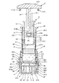
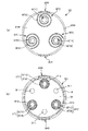
図1は、本発明のシリンジの第1実施形態を示す斜視図、図2は、図1に示すシリンジの断面図、図3は、図1に示すシリンジの側面図、図4は、図1に示すシリンジの平面図、図5、図6および図7は、図1に示すシリンジの使用方法を説明するための断面図である。なお、以下では、説明の都合上、図1(図2、図3、図5〜図7についても同様)中の上側を「基端」、下側を「先端」という。また、以下では、図1および図2の状態を初期状態(未使用状態)とも言う。また、図4は、シリンジを基端側から見た平面図であるが、キャップの図示を省略している。
Hereinafter, the syringe of this invention is demonstrated in detail based on suitable embodiment shown to an accompanying drawing.
<First Embodiment>
1 is a perspective view showing a first embodiment of the syringe of the present invention, FIG. 2 is a sectional view of the syringe shown in FIG. 1, FIG. 3 is a side view of the syringe shown in FIG. 1, and FIG. FIG. 5, FIG. 6 and FIG. 7 are cross-sectional views for explaining a method of using the syringe shown in FIG. Hereinafter, for convenience of explanation, the upper side in FIG. 1 (the same applies to FIGS. 2, 3, and 5 to 7) is referred to as “base end”, and the lower side is referred to as “tip”. Hereinafter, the state of FIGS. 1 and 2 is also referred to as an initial state (unused state). FIG. 4 is a plan view of the syringe as seen from the proximal end side, but the illustration of the cap is omitted.

図1に示すシリンジ1は、内部に予め薬液100が収納された自己投与型のプレフィルドシリンジである。   A syringe 1 shown in FIG. 1 is a self-administered prefilled syringe in which a drug solution 100 is previously stored.

このようなシリンジ1は、外筒2と、外筒に装着される両頭針3と、外筒2内で摺動し得るガスケット4と、ガスケット4を移動操作する第1押し子(押し子)5と、第1押し子5を移動操作する第2押し子(押し子)6と、外筒2に対して第2押し子6を固定する固定手段7と、両頭針3を覆う安全カバー(内蓋体)9およびキャップ(蓋体)8と、を有している。   Such a syringe 1 includes an outer cylinder 2, a double-ended needle 3 attached to the outer cylinder, a gasket 4 that can slide in the outer cylinder 2, and a first pusher (pusher) that moves the gasket 4. 5, a second pusher (pusher) 6 that moves the first pusher 5, a fixing means 7 that fixes the second pusher 6 to the outer cylinder 2, and a safety cover that covers the double-ended needle 3 ( An inner lid body 9 and a cap (lid body) 8.

また、図2に示すように、シリンジ1では、外筒2とガスケット4とで囲まれる空間であって、ガスケット4の先端側に位置する空間S1内に、予め液状の薬液100が収納されている。薬液100としては、特に限定されず、例えば、抗体等の蛋白質性医薬品、低分子蛋白質、ホルモン等のペプチド性医薬品、核酸医薬品、細胞医薬品、血液製剤、各種感染症を予防するワクチン、抗がん剤、麻酔薬、麻薬、抗生物質、ステロイド剤、蛋白質分解酵素阻害剤、ヘパリン、ブドウ糖等の糖質注射液、塩化ナトリウムや乳酸カリウム等の電解質補正用注射液、ビタミン剤、脂肪乳剤、造影剤等が挙げられる。   In addition, as shown in FIG. 2, in the syringe 1, a liquid chemical solution 100 is stored in advance in a space S <b> 1 that is surrounded by the outer cylinder 2 and the gasket 4 and is located on the tip side of the gasket 4. Yes. The drug solution 100 is not particularly limited. For example, protein drugs such as antibodies, low molecular weight proteins, peptide drugs such as hormones, nucleic acid drugs, cell drugs, blood products, vaccines for preventing various infectious diseases, anticancer drugs, etc. Agents, anesthetics, narcotics, antibiotics, steroids, proteolytic enzyme inhibitors, sugar injection solutions such as heparin and glucose, electrolyte correction injection solutions such as sodium chloride and potassium lactate, vitamins, fat emulsions, contrast agents Etc.

なお、シリンジ1に収納される薬液100の容量としては、薬液100の種類によっても異なるが、例えば、0.02〜10mLであるのが好ましく、0.05〜1.2mLであるのがより好ましい。   In addition, as a capacity | capacitance of the chemical | medical solution 100 accommodated in the syringe 1, although it changes also with the kind of chemical | medical solution 100, it is preferable that it is 0.02-10mL, for example, and it is more preferable that it is 0.05-1.2mL. .

以下、シリンジ1の各部位について順次詳細に説明する。
−外筒−
外筒2は、有底筒状の部材で構成されている。また、外筒2は、筒状の胴部21と、胴部21の先端側の開口212を封止する封止体23と、胴部21の先端外周に設けられた一対の羽根251、252と、胴部21の外周に設けられた一対の固定部271、272と、胴部21の基端外周に設けられたフランジ29とを有している。
Hereinafter, each site | part of the syringe 1 is demonstrated in detail sequentially.
-Outer cylinder-
The outer cylinder 2 is composed of a bottomed cylindrical member. The outer cylinder 2 includes a cylindrical body portion 21, a sealing body 23 that seals the opening 212 on the distal end side of the body portion 21, and a pair of blades 251 and 252 provided on the outer periphery of the distal end of the body portion 21. And a pair of fixing portions 271 and 272 provided on the outer periphery of the trunk portion 21 and a flange 29 provided on the outer periphery of the proximal end of the trunk portion 21.

胴部21の内周面213には、その軸に沿って延びる複数の溝215が周方向に離間して形成されている。これら各溝215は、後述するように、第1押し子5とガスケット4との間の空間S2の空気を逃がす機能を有する。   A plurality of grooves 215 extending along the axis are formed in the inner peripheral surface 213 of the body portion 21 so as to be separated from each other in the circumferential direction. Each of these grooves 215 has a function of releasing the air in the space S2 between the first pusher 5 and the gasket 4 as will be described later.

また、胴部21には、その先端面に開放し、開口212の周囲を囲む環状の溝215が形成されている。また、溝215の開口付近には、溝215の内側へ突出する段差部215aが形成されている。この溝215には、後述するように、安全カバー9の側壁92が摺動可能に挿入されている。さらには、側壁92に形成されたフランジ(突起)93が段差部215aに基端側から当接することにより、安全カバー9の外筒2からの離脱が防止されている。   Further, the body portion 21 is formed with an annular groove 215 that opens to the front end surface and surrounds the periphery of the opening 212. A stepped portion 215 a that protrudes inward of the groove 215 is formed in the vicinity of the opening of the groove 215. As will be described later, the side wall 92 of the safety cover 9 is slidably inserted into the groove 215. Furthermore, the flange (projection) 93 formed on the side wall 92 abuts on the stepped portion 215a from the base end side, thereby preventing the safety cover 9 from being detached from the outer cylinder 2.

また、溝215内には、コイルバネ(付勢部材)10が設けられており、コイルバネ10によって安全カバー9が外筒2に対して先端側へ付勢されている。   Further, a coil spring (biasing member) 10 is provided in the groove 215, and the safety cover 9 is biased toward the distal end side with respect to the outer cylinder 2 by the coil spring 10.

一対の羽根251、252は、胴部21に対して互いに反対側に設けられている。このような羽根251、252は、胴部21の軸を法線とする平面に広がりを有しており、後述するように、シリンジ1の使用時に、使用者が指を引っ掛けるのに用いることができる。これにより、シリンジ1を皮膚に対して容易に押し当てるこができ、シリンジ1の姿勢を簡単に維持することができる。そのため、薬液100の注入(投与)を簡単かつ確実に行うことができる。   The pair of blades 251 and 252 are provided on the opposite sides with respect to the trunk portion 21. Such blades 251 and 252 have a plane that is normal to the axis of the trunk portion 21 and, as will be described later, when the syringe 1 is used, the user can hook the finger. it can. Thereby, the syringe 1 can be easily pressed against the skin, and the posture of the syringe 1 can be easily maintained. Therefore, injection (administration) of the chemical solution 100 can be performed easily and reliably.

一対の固定部271、272は、キャップ8を固定する機能を有する。これら一対の固定部271、272は、胴部21に対して互いに反対側に設けられている。   The pair of fixing portions 271 and 272 have a function of fixing the cap 8. The pair of fixing portions 271 and 272 are provided on the opposite sides of the body portion 21.

図3(a)に示すように、固定部271は、胴部21の周方向に離間して並設された一対の固定片271a、271bを有している。これら固定片271a、271bは、外筒2の外周に沿って、かつ、外筒2の外周面と間隔を隔てて設けられている。固定片271aは、羽根251から基端側へ延出して設けられており、固定片271bは、羽根252から基端側へ延出して設けられている。   As shown in FIG. 3A, the fixing portion 271 has a pair of fixing pieces 271 a and 271 b that are arranged side by side in the circumferential direction of the body portion 21. These fixed pieces 271a and 271b are provided along the outer periphery of the outer cylinder 2 and spaced from the outer peripheral surface of the outer cylinder 2. The fixed piece 271a extends from the blade 251 to the proximal end side, and the fixed piece 271b extends from the blade 252 to the proximal end side.

同様に、図3(b)に示すように、固定部272は、外筒2の周方向に離間して並設された一対の固定片272a、272bを有している。これら固定片272a、272bは、外筒2の外周面に沿って、かつ、外筒2の外周と間隔を隔てて設けられている。固定片272aは、羽根251から基端側へ延出して設けられており、固定片272bは、羽根252から基端側へ延出して設けられている。   Similarly, as shown in FIG. 3 (b), the fixing portion 272 has a pair of fixing pieces 272 a and 272 b that are arranged side by side in the circumferential direction of the outer cylinder 2. These fixed pieces 272a and 272b are provided along the outer peripheral surface of the outer cylinder 2 and spaced from the outer periphery of the outer cylinder 2. The fixed piece 272a extends from the blade 251 to the proximal end side, and the fixed piece 272b extends from the blade 252 to the proximal end side.

固定片271a、271bと外筒2の外周との間に、キャップ8が有する後述する係合部831を配置し、固定片272a、272bと外筒2の外周との間に、キャップ8が有する後述する係合部851を配置することにより、外筒2にキャップ8が固定されている。   An engaging portion 831 (described later) of the cap 8 is disposed between the fixing pieces 271a and 271b and the outer periphery of the outer cylinder 2, and the cap 8 is provided between the fixing pieces 272a and 272b and the outer periphery of the outer cylinder 2. The cap 8 is fixed to the outer cylinder 2 by disposing an engaging portion 851 described later.

固定片271a、271bの離間距離は、キャップ8が有する後述する連結部833の幅(外筒2の周方向における長さ)よりも大きく、係合部831の幅よりも小さい。また、羽根251の外筒2と固定片271aの間の領域、および、羽根252の外筒2と固定片271bの間の領域がそれぞれ除去されており、これら領域に切り欠き28が形成されている。   The separation distance between the fixing pieces 271a and 271b is larger than the width of a connecting portion 833 (the length in the circumferential direction of the outer cylinder 2) described later, which the cap 8 has, and is smaller than the width of the engaging portion 831. Further, the region between the outer cylinder 2 and the fixed piece 271a of the blade 251 and the region between the outer tube 2 and the fixed piece 271b of the blade 252 are removed, and a notch 28 is formed in these regions. Yes.

同様に、固定片272a、272bの離間距離は、キャップ8が有する後述する連結部853の幅(外筒2の周方向における長さ)よりも大きく、係合部851の幅よりも小さい。また、図示しないが、羽根251の外筒2と固定片272aの間の領域、および、羽根252の外筒2と固定片272bの間の領域がそれぞれ除去されており、これら領域に切り欠き28が形成されている。   Similarly, the separation distance between the fixing pieces 272a and 272b is larger than the width of the connecting portion 853 (the length in the circumferential direction of the outer cylinder 2), which will be described later, of the cap 8, and smaller than the width of the engaging portion 851. Although not shown, the region between the outer cylinder 2 and the fixed piece 272a of the blade 251 and the region between the outer tube 2 and the fixed piece 272b of the blade 252 are removed, and a notch 28 is cut into these regions. Is formed.

ここで、キャップ8の外筒2への装着(固定)は、係合部831を先端側から固定片271a、271bと外筒2の外周面との間に挿入するとともに、係合部851を先端側から固定片272a、272bと外筒2の外周面との間に挿入して行われる。前記切り欠き28は、このような外筒2へのキャップ8の装着を行うために形成されている。   Here, when the cap 8 is attached (fixed) to the outer cylinder 2, the engaging portion 831 is inserted between the fixing pieces 271 a and 271 b and the outer peripheral surface of the outer cylinder 2 from the tip side, and the engaging portion 851 is inserted. It is carried out by inserting between the fixed pieces 272a, 272b and the outer peripheral surface of the outer cylinder 2 from the front end side. The notch 28 is formed in order to attach the cap 8 to the outer cylinder 2 as described above.

外筒2の構成材料としては、特に限定されず、例えば、ポリ塩化ビニル、ポリエチレン、ポリプロピレン、環状オレフィンの単独重合体(COP)や環状オレフィンの共重合体(COC)などの環状ポリオレフィン、ポリスチレン、ポリ−(4−メチルペンテン−1)、ポリカーボネート、アクリル樹脂、アクリルニトリル−ブタジエン−スチレン共重合体、ポリエチレンテレフタレート、ポリエチレンナフタレート等のポリエステル、ブタジエン−スチレン共重合体、ポリアミド(例えば、ナイロン6、ナイロン6・6、ナイロン6・10、ナイロン12)のような各種樹脂が挙げられるが、その中でも、透明性や成形が容易であるという点で、ポリプロピレン、環状ポリオレフィン、ポリエステル、ポリ−(4−メチルペンテン−1)のような樹脂が好ましい。   The constituent material of the outer cylinder 2 is not particularly limited. For example, polyvinyl chloride, polyethylene, polypropylene, cyclic polyolefin such as cyclic olefin homopolymer (COP) or cyclic olefin copolymer (COC), polystyrene, Poly- (4-methylpentene-1), polycarbonate, acrylic resin, acrylonitrile-butadiene-styrene copolymer, polyester such as polyethylene terephthalate, polyethylene naphthalate, butadiene-styrene copolymer, polyamide (for example, nylon 6, Various resins such as nylon 6,6, nylon 6,10, nylon 12) can be mentioned. Among them, polypropylene, cyclic polyolefin, polyester, poly- (4- Of methylpentene-1) UNA resin is preferable.

なお、外筒2(特に、胴部21)は、内部の視認性を確保するために、実質的に透明であるのが好ましい。   In addition, it is preferable that the outer cylinder 2 (especially trunk | drum 21) is substantially transparent in order to ensure internal visibility.

−ガスケット−
外筒2内には、弾性材料で構成されたガスケット4が収納されている。ガスケット4の外周部には、複数のリング状の突部が全周にわたって形成されている。この突部が外筒2の内周面213に対し密着しつつ摺動することにより、液密性をより確実に保持するとともに、摺動性の向上を図ることができる。
-Gasket-
A gasket 4 made of an elastic material is accommodated in the outer cylinder 2. A plurality of ring-shaped protrusions are formed on the outer periphery of the gasket 4 over the entire periphery. By sliding the projecting portion in close contact with the inner peripheral surface 213 of the outer cylinder 2, the liquid tightness can be more reliably maintained and the slidability can be improved.

このようなガスケット4の構成材料としては、特に限定されず、例えば、天然ゴム、ブチルゴム、イソプレンゴム、ブタジエンゴム、スチレン−ブタジエンゴム、シリコーンゴムのような各種ゴム材料や、ポリウレタン系、ポリエステル系、ポリアミド系、オレフィン系、スチレン系等の各種熱可塑性エラストマー、あるいはそれらの混合物等の弾性材料が挙げられる。   The constituent material of such a gasket 4 is not particularly limited. For example, various rubber materials such as natural rubber, butyl rubber, isoprene rubber, butadiene rubber, styrene-butadiene rubber, silicone rubber, polyurethane, polyester, Examples thereof include various thermoplastic elastomers such as polyamide, olefin, and styrene, or elastic materials such as a mixture thereof.

−第1押し子−
第1押し子5は、外筒2に対して、外筒2の長手方向に移動可能に設けられている。第1押し子5は、先端側に底部511を有する有底筒状の本体51と、本体51の周囲に設けられ、胴部21の内周面213と摺動するガスケット53とを有している。
-First pusher-
The first pusher 5 is provided to be movable in the longitudinal direction of the outer cylinder 2 with respect to the outer cylinder 2. The first pusher 5 includes a bottomed cylindrical main body 51 having a bottom portion 511 on the distal end side, and a gasket 53 that is provided around the main body 51 and slides on the inner peripheral surface 213 of the body portion 21. Yes.

本体51は、胴部21の内径よりも小さい外径を有しており、外筒2の基端側から胴部21内に挿入されている。また、図2に示すように、第1押し子5が外筒2に対して移動していない初期状態では、本体51は、ガスケット4と離間している。なお、この離間距離は、特に限定されないが、1〜20mm程度であるのが好ましく、3〜7mm程度であるのがより好ましい。   The main body 51 has an outer diameter smaller than the inner diameter of the trunk portion 21, and is inserted into the trunk portion 21 from the proximal end side of the outer cylinder 2. In addition, as shown in FIG. 2, the main body 51 is separated from the gasket 4 in an initial state where the first pusher 5 is not moved with respect to the outer cylinder 2. In addition, although this separation distance is not specifically limited, It is preferable that it is about 1-20 mm, and it is more preferable that it is about 3-7 mm.

本体51の先端部には、外周へ突出するリング状の突出部513が形成されており、この突出部513に係合してガスケット53が設けられている。これにより、ガスケット53の本体51からの離脱が効果的に防止されている。ガスケット53は、本体51に固定されているとともに、胴部21の内周面213に密着している。   A ring-shaped protrusion 513 that protrudes to the outer periphery is formed at the tip of the main body 51, and a gasket 53 is provided to engage with the protrusion 513. Thereby, the detachment | leave from the main body 51 of the gasket 53 is prevented effectively. The gasket 53 is fixed to the main body 51 and is in close contact with the inner peripheral surface 213 of the body portion 21.

このような構成の第1押し子5は、ガスケット53が胴部21の内周面213に密着しつつ摺動することにより、外筒2に対して先端側へ移動し、ガスケット4に接触するとともにガスケット4を押圧する。なお、第1押し子5がガスケット4に接近する際、第1押し子5とガスケット4とで挟まれた空間S2内にある空気は、複数の溝215を通って外部へ逃げる。   The first pusher 5 having such a configuration moves toward the distal end side with respect to the outer cylinder 2 and comes into contact with the gasket 4 when the gasket 53 slides in close contact with the inner peripheral surface 213 of the body portion 21. At the same time, the gasket 4 is pressed. Note that when the first pusher 5 approaches the gasket 4, the air in the space S <b> 2 sandwiched between the first pusher 5 and the gasket 4 escapes through the plurality of grooves 215.

本体51の構成材料としては、特に限定されず、例えば、ポリ塩化ビニル、ポリエチレン、ポリプロピレン、ポリスチレン、ポリ−(4−メチルペンテン−1)、ポリカーボネート、アクリル樹脂、アクリルニトリル−ブタジエン−スチレン共重合体、ポリエチレンテレフタレート、ポリエチレンナフタレート等のポリエステル、ブタジエン−スチレン共重合体、ポリアセタール、ポリアミド(例えば、ナイロン6、ナイロン6・6、ナイロン6・10、ナイロン12)のような各種樹脂が挙げられるが、その中でも、成形が容易であるという点で、ポリプロピレン、ポリエステル、ポリ−(4−メチルペンテン−1)のような樹脂が好ましい。   The constituent material of the main body 51 is not particularly limited. For example, polyvinyl chloride, polyethylene, polypropylene, polystyrene, poly- (4-methylpentene-1), polycarbonate, acrylic resin, acrylonitrile-butadiene-styrene copolymer. Various resins such as polyesters such as polyethylene terephthalate and polyethylene naphthalate, butadiene-styrene copolymers, polyacetals, polyamides (for example, nylon 6, nylon 6,6, nylon 6,10, nylon 12), Among them, a resin such as polypropylene, polyester, and poly- (4-methylpentene-1) is preferable because it is easy to mold.

また、ガスケット53の構成材料としては、特に限定されず、例えば、前述したガスケット4と同様の材料が挙げられる。   Moreover, it does not specifically limit as a constituent material of the gasket 53, For example, the material similar to the gasket 4 mentioned above is mentioned.

−第2押し子−
第2押し子6は、第1押し子5に対して、先端側へ移動可能に設けられている。第2押し子6は、本体61と、本体61の周囲に設けられ、第1押し子5の内周面515と摺動するガスケット63とを有している。
-Second pusher-
The second pusher 6 is provided so as to be movable toward the tip side with respect to the first pusher 5. The second pusher 6 includes a main body 61 and a gasket 63 that is provided around the main body 61 and slides with an inner peripheral surface 515 of the first pusher 5.

本体61は、横断面が十文字をなす棒状の基部611と、基部611の先端に形成された先端部613と、基部611の基端に形成されたフランジ615とを有し、これらが一体的に形成されている。このような本体61は、外筒2の基端側から第1押し子5の本体51内に挿入されており、先端部613が本体51内に位置し、フランジ615が本体51から突出して位置している。このような第2押し子6は、フランジ615に指等を掛けて操作する。なお、基部611の横断面形状は、十文字に限定されず、例えば、円形であってもよい。   The main body 61 has a rod-like base 611 having a cross-sectional cross section, a tip 613 formed at the tip of the base 611, and a flange 615 formed at the base of the base 611. Is formed. Such a main body 61 is inserted into the main body 51 of the first pusher 5 from the base end side of the outer cylinder 2, the distal end portion 613 is located in the main body 51, and the flange 615 is projected from the main body 51. doing. Such a second pusher 6 is operated by placing a finger or the like on the flange 615. In addition, the cross-sectional shape of the base 611 is not limited to a cross shape, and may be, for example, a circle.

先端部613には、外周へ突出するリング状の突起613aが形成されており、この突起613aに係合するようにガスケット63が設けられている。ガスケット63は、先端部613の周囲を囲んで設けられているとともに、本体51の内周面515に気密的に接触している。   The tip portion 613 is formed with a ring-shaped protrusion 613a that protrudes to the outer periphery, and a gasket 63 is provided so as to engage with the protrusion 613a. The gasket 63 is provided so as to surround the front end portion 613 and is in airtight contact with the inner peripheral surface 515 of the main body 51.

また、先端部613には、先端部613の先端側と基端側とを連通する連通孔613bが形成されている。この連通孔613bには、フィルタ65が設けられている。フィルタ65は、通気抵抗を調節するためのものであり、フィルタ65を配置しない場合と比較して、連通孔613b内を空気が通過し難くなっている。このようなフィルタ65は、通気抵抗を調整することができれば、特に限定されず、メッシュフィルタ等を用いることができる。   In addition, a communication hole 613b that connects the distal end side and the proximal end side of the distal end portion 613 is formed in the distal end portion 613. A filter 65 is provided in the communication hole 613b. The filter 65 is for adjusting the ventilation resistance, and it is difficult for air to pass through the communication hole 613b as compared with the case where the filter 65 is not disposed. Such a filter 65 is not particularly limited as long as the ventilation resistance can be adjusted, and a mesh filter or the like can be used.

なお、フィルタ65は、省略してもよく、この場合には、連通孔613bの径の大きさを制御することにより、連通孔613b内の空気の通過のし易さを調節することができる。また、連通孔613bを省略し、その代わりに、本体51の内周面515に空間S3の内外を連通する溝(すなわち、前述した溝215と同様の機能を有する溝)を形成してもよい。   The filter 65 may be omitted. In this case, the ease of passage of air in the communication hole 613b can be adjusted by controlling the size of the diameter of the communication hole 613b. Further, the communication hole 613b may be omitted, and instead, a groove that communicates the inside and outside of the space S3 (that is, a groove having the same function as the groove 215 described above) may be formed on the inner peripheral surface 515 of the main body 51. .

このような構成の第2押し子6は、ガスケット63が本体51の内周面515に密着しつつ摺動することにより、第1押し子5に対して先端側へ移動する。この際、第1押し子5と第2押し子6とで囲まれる空間であって、第2押し子6の先端側に位置する空間S3内にある空気は、連通孔613b(フィルタ65)を通って外部へ逃げる。   The second pusher 6 having such a configuration moves toward the distal end side with respect to the first pusher 5 when the gasket 63 slides in close contact with the inner peripheral surface 515 of the main body 51. At this time, the air in the space S3 located between the first pusher 5 and the second pusher 6 and located on the tip side of the second pusher 6 passes through the communication hole 613b (filter 65). Escape to the outside.

本体61の構成材料としては、特に限定されず、例えば、前述した第1押し子5の本体51の構成材料と同様の材料を用いることができる。また、ガスケット63の構成材料としては、特に限定されず、例えば、前述した第1押し子5のガスケット53の構成材料と同様の材料を用いることができる。   The constituent material of the main body 61 is not particularly limited, and for example, the same material as the constituent material of the main body 51 of the first pusher 5 described above can be used. Moreover, it does not specifically limit as a constituent material of the gasket 63, For example, the material similar to the constituent material of the gasket 53 of the 1st pusher 5 mentioned above can be used.

−固定手段−
固定手段7は、第2押し子6の第1押し子5に対する移動が完了した後に、第2押し子が基端側へ移動するのを防止する機能を有している。これにより、第2押し子6が初期状態へ復帰するのを防止することができる。
-Fixing means-
The fixing means 7 has a function of preventing the second pusher 6 from moving to the proximal end side after the movement of the second pusher 6 with respect to the first pusher 5 is completed. Thereby, it is possible to prevent the second pusher 6 from returning to the initial state.

図1および図2に示すように、固定手段7は、第2押し子6のフランジ615に形成された複数の爪部71を有している。各爪部71は、フランジ615の先端側の面から先端側へ突出して設けられている。このような構成の固定手段7は、後述するように、第2押し子6の第1押し子5に対する移動が完了するとともに各爪部71が外筒2のフランジ29に嵌合するように構成されており、嵌合した後の第2押し子の基端側への移動を防止している。これにより、シリンジ1の操作性および安全性が向上する。   As shown in FIGS. 1 and 2, the fixing means 7 has a plurality of claw portions 71 formed on the flange 615 of the second pusher 6. Each claw portion 71 is provided so as to protrude from the front end surface of the flange 615 to the front end side. The fixing means 7 having such a configuration is configured so that the movement of the second pusher 6 relative to the first pusher 5 is completed and each claw portion 71 is fitted to the flange 29 of the outer cylinder 2 as will be described later. Thus, movement of the second pusher to the base end side after the fitting is prevented. Thereby, the operativity and safety | security of the syringe 1 improve.

なお、固定手段7の構成は、上述した機能を発揮することができれば、特に限定されず、例えば、本実施形態とは逆に、外筒2のフランジ29に複数の爪部71を設け、この爪部71を第2押し子6のフランジ615に嵌合させるような構成でもよい。また、外筒2のフランジ29に複数の爪部71を設け、第2押し子6のフランジ615に、嵌合孔を形成し、複数の爪部71を前記嵌合孔に嵌合させる構成としてもよい。また、第1押し子5の上下に爪部71が設けられ、外筒2および第2押し子6のそれぞれに嵌合孔が形成された構成としてもよい。すなわち、爪部71の一方が外筒2の嵌合孔と嵌合し、他方が第2押し子6の嵌合孔に嵌合するような構成としてもよい。   The configuration of the fixing means 7 is not particularly limited as long as the function described above can be exhibited. For example, contrary to the present embodiment, a plurality of claw portions 71 are provided on the flange 29 of the outer cylinder 2, A configuration in which the claw portion 71 is fitted to the flange 615 of the second pusher 6 may be employed. Further, a configuration is provided in which a plurality of claw portions 71 are provided on the flange 29 of the outer cylinder 2, a fitting hole is formed in the flange 615 of the second pusher 6, and the plurality of claw portions 71 are fitted into the fitting holes. Also good. Moreover, it is good also as a structure by which the nail | claw part 71 was provided in the upper and lower sides of the 1st pusher 5, and the fitting hole was formed in each of the outer cylinder 2 and the 2nd pusher 6. FIG. That is, one of the claw portions 71 may be fitted into the fitting hole of the outer cylinder 2 and the other may be fitted into the fitting hole of the second pusher 6.

−安全カバー9−
安全カバー9は、両頭針3を覆っており、キャップ8をシリンジ1から外した際に両頭針3が外部に露出するのを防止する機能を有している。このような安全カバー9を有することにより、両頭針3による不慮の刺傷を防止することができ、シリンジ1の安全性が向上する。
-Safety cover 9-
The safety cover 9 covers the double-ended needle 3 and has a function of preventing the double-ended needle 3 from being exposed to the outside when the cap 8 is removed from the syringe 1. By having such a safety cover 9, accidental puncture by the double-ended needle 3 can be prevented, and the safety of the syringe 1 is improved.

安全カバー9は、有底筒状をなしている。具体的には、安全カバー9は、板状の底部91と、底部91の周囲から基端側へ向けて立設する筒状の側壁92と、側壁92の基端外周に形成されたフランジ93とを有している。前述したように、安全カバー9は、側壁92が外筒2の溝215内に挿入された状態で設けられている。また、フランジ93が溝215の段差部215aに当接することにより、安全カバー9の溝215からの離脱が防止されている。また、安全カバー9は、溝215内に配置されたコイルバネ10によって外筒2に対して先端側へ付勢されている。このような安全カバー9は、コイルバネ10の付勢力に逆らうことにより、外筒2に対して基端側へ移動させることができる。   The safety cover 9 has a bottomed cylindrical shape. Specifically, the safety cover 9 includes a plate-shaped bottom portion 91, a cylindrical side wall 92 erected from the periphery of the bottom portion 91 toward the base end side, and a flange 93 formed on the base end outer periphery of the side wall 92. And have. As described above, the safety cover 9 is provided with the side wall 92 inserted into the groove 215 of the outer cylinder 2. Further, the flange 93 is in contact with the step portion 215a of the groove 215, so that the safety cover 9 is prevented from being detached from the groove 215. The safety cover 9 is urged toward the distal end side with respect to the outer cylinder 2 by a coil spring 10 disposed in the groove 215. Such a safety cover 9 can be moved to the base end side with respect to the outer cylinder 2 by countering the urging force of the coil spring 10.

また、底部91には、安全カバー9を外筒2に対して基端側へ移動させた際に、両頭針3を通過させる複数の両頭針用孔911が形成されている。また、底部91には、キャップ8が有する後述する支持部87を通過させる複数の支持部用孔913が形成されている。両頭針用孔911は、両頭針3の数に対応して3つ形成され、支持部用孔913は、支持部87の数に対応して3つ形成されている。   The bottom 91 is formed with a plurality of double-ended needle holes 911 through which the double-ended needle 3 passes when the safety cover 9 is moved to the proximal end side with respect to the outer cylinder 2. The bottom portion 91 is formed with a plurality of support portion holes 913 that allow a later-described support portion 87 of the cap 8 to pass therethrough. Three double-ended needle holes 911 are formed corresponding to the number of double-ended needles 3, and three support portion holes 913 are formed corresponding to the number of support portions 87.

本実施形態では、図4に示すように、3つの両頭針用孔911は、外筒2の軸まわりにほぼ等間隔(ほぼ120°間隔)で形成されており、3つの支持部用孔913も、外筒2の軸まわりにほぼ等間隔(ほぼ120°間隔)で形成されている。また、両頭針用孔911と支持部用孔913とが外筒2の軸まわりに交互に形成されている。   In the present embodiment, as shown in FIG. 4, the three double-ended needle holes 911 are formed at almost equal intervals (approximately 120 ° intervals) around the axis of the outer cylinder 2, and the three support portion holes 913 are formed. Are formed at substantially equal intervals (approximately 120 ° intervals) around the axis of the outer cylinder 2. Further, double-ended needle holes 911 and support portion holes 913 are alternately formed around the axis of the outer cylinder 2.

また、側壁92の外周面には、軸方向へ延在するガイド溝921が形成されている。このガイド溝921は、キャップ8の軸まわりの回転を防止する機能を有している。   A guide groove 921 extending in the axial direction is formed on the outer peripheral surface of the side wall 92. The guide groove 921 has a function of preventing rotation around the axis of the cap 8.

−キャップ8−
キャップ8は、外筒2の先端側に設けられており、未使用時において両頭針3および安全カバー9を覆うことにより両頭針3の露出を防止する機能を有している。そのため、両頭針3による不慮の刺傷を防止することができ、また、使用前(穿刺前)の両頭針3の汚染を防止することができる。このようなキャップ8を有することにより、シリンジ1の安全性が向上する。
-Cap 8-
The cap 8 is provided on the distal end side of the outer cylinder 2 and has a function of preventing the double-ended needle 3 from being exposed by covering the double-ended needle 3 and the safety cover 9 when not in use. Therefore, accidental puncture by the double-ended needle 3 can be prevented, and contamination of the double-ended needle 3 before use (before puncturing) can be prevented. By having such a cap 8, the safety of the syringe 1 is improved.

キャップ8は、有底筒状の本体81と、本体81から基端側へ延出する一対の腕部83、85と、本体81の内側に形成された3つの支持部87とを有している。   The cap 8 has a bottomed cylindrical main body 81, a pair of arm portions 83 and 85 extending from the main body 81 toward the base end side, and three support portions 87 formed inside the main body 81. Yes.

また、本体81は、板状の底部811と、底部811の周囲から基端側へ立設する筒状の側壁813と、側壁813の内周面に形成され、軸方向へ延在する突起815とを有している。   The main body 81 has a plate-like bottom portion 811, a cylindrical side wall 813 erected from the periphery of the bottom portion 811 to the base end side, and a protrusion 815 that is formed on the inner peripheral surface of the side wall 813 and extends in the axial direction. And have.

このような本体81は、安全カバー9を外側(先端側)から覆い、かつ、突起815が安全カバーのガイド溝921に係合した状態で配置されている。また、初期状態では、本体81は、胴部21と外筒2の軸方向に離間している。また、本体81の内径は、安全カバー9の外径と等しいか若干大きく設定されている。そのため、本体81は、ガイド溝921に沿って安全カバー9と摺動する。これにより、安全カバー9に対するキャップ8のぐらつきやキャップ8の軸まわりの回転を防止することができ、シリンジ1の操作性が向上する。   Such a main body 81 is arranged in a state in which the safety cover 9 is covered from the outside (front end side) and the projection 815 is engaged with the guide groove 921 of the safety cover. In the initial state, the main body 81 is separated in the axial direction of the body portion 21 and the outer cylinder 2. The inner diameter of the main body 81 is set to be equal to or slightly larger than the outer diameter of the safety cover 9. Therefore, the main body 81 slides with the safety cover 9 along the guide groove 921. Thereby, the wobbling of the cap 8 with respect to the safety cover 9 and the rotation around the axis of the cap 8 can be prevented, and the operability of the syringe 1 is improved.

3つの支持部87は、安全カバー9内にて、両頭針3を支持する機能を有している。これら支持部87は、それぞれ、柱状をなしており、底部811から基端側へ突出して設けられている。また、これら支持部87は、安全カバー9に形成された支持部用孔913を介して安全カバー9内に侵入している。   The three support portions 87 have a function of supporting the double-ended needle 3 within the safety cover 9. Each of these support portions 87 has a columnar shape, and is provided so as to protrude from the bottom portion 811 to the base end side. Further, these support portions 87 enter the safety cover 9 through support portion holes 913 formed in the safety cover 9.

一対の腕部83、85は、本体81の軸に対して対称的に形成されている。腕部83は、図3(a)に示すように、外筒2の周方向へ延在する係合部831と、係合部831と本体81とを連結する連結部(変形部)833とを有している。同様に、腕部85は、図3(b)に示すように、外筒2の周方向へ延在する係合部851と、係合部851と本体81とを連結する連結部(変形部)853とを有している。   The pair of arm portions 83 and 85 are formed symmetrically with respect to the axis of the main body 81. As shown in FIG. 3A, the arm portion 83 includes an engaging portion 831 extending in the circumferential direction of the outer cylinder 2, and a connecting portion (deforming portion) 833 that connects the engaging portion 831 and the main body 81. have. Similarly, as shown in FIG. 3B, the arm portion 85 includes an engaging portion 851 extending in the circumferential direction of the outer cylinder 2 and a connecting portion (deforming portion) that connects the engaging portion 851 and the main body 81. ) 853.

初期状態では、腕部83の係合部831が外筒2の外周面と固定部271との間に挿入されており、腕部85の係合部851が外筒2の外周面と固定部272との間に挿入されている。これにより、キャップ8が外筒2に固定されている。   In the initial state, the engaging portion 831 of the arm portion 83 is inserted between the outer peripheral surface of the outer cylinder 2 and the fixing portion 271, and the engaging portion 851 of the arm portion 85 is inserted into the outer peripheral surface of the outer cylinder 2 and the fixing portion. 272. Thereby, the cap 8 is fixed to the outer cylinder 2.

ここで、各腕部83、85の連結部833、853は、自然状態(外力が実質的に加わっていない状態)では、基端側へ向けて外側に広がるように傾斜している。また、これら連結部833、853は、それぞれ、弾性変形可能に形成されており、図1および図2に示すように、キャップ8が外筒2に固定されている状態では内側(外筒2側)へ弾性変形している。   Here, in the natural state (a state in which no external force is substantially applied), the connecting portions 833 and 853 of the arm portions 83 and 85 are inclined so as to spread outward toward the base end side. Each of the connecting portions 833 and 853 is formed so as to be elastically deformable, and as shown in FIGS. 1 and 2, the cap 8 is fixed to the outer cylinder 2 on the inner side (the outer cylinder 2 side). ) Is elastically deformed.

−両頭針3−
本実施形態のシリンジ1では、安全カバー9内に3本の両頭針3が収納されている。シリンジ1が3本(複数)の両頭針3を有することにより、穿刺時の痛みを和らげることができるとともに、薬液100の投与にかかる時間を短縮することができる。なお、両頭針3の数としては、3本に限定されず、例えば、1本または2本であってもよいし、4本以上であってもよい。
-Double-ended needle 3-
In the syringe 1 of the present embodiment, three double-ended needles 3 are housed in a safety cover 9. Since the syringe 1 has three (plurality) double-ended needles 3, pain during puncture can be relieved and the time required for administration of the drug solution 100 can be shortened. Note that the number of double-ended needles 3 is not limited to three, and may be one or two, for example, or four or more.

これら3本の両頭針3は、封止体23と対向して配置されている。また、3本の両頭針3は、外筒2の軸まわりに等間隔(すなわち120°間隔)で配置されている。また、3本の両頭針3は、それぞれ、安全カバー9に形成された両頭針用孔911に対向して設けられている。そのため、安全カバー9が外筒2に対して基端側へ移動したときに、各両頭針3が両頭針用孔911を介して安全カバー9の外部へ突出することができる。   These three double-ended needles 3 are disposed to face the sealing body 23. The three double-ended needles 3 are arranged at equal intervals (that is, at 120 ° intervals) around the axis of the outer cylinder 2. Further, the three double-ended needles 3 are respectively provided to face double-ended needle holes 911 formed in the safety cover 9. Therefore, when the safety cover 9 moves to the proximal end side with respect to the outer cylinder 2, each double-ended needle 3 can protrude outside the safety cover 9 via the double-ended needle hole 911.

このような3本の両頭針3は、それぞれ、板状の両頭針支持板39に刺通、支持されている。さらに、両頭針支持板39は、安全カバー9内に臨む3つの支持部87に支持されている。すなわち、3本の両頭針3は、両頭針支持板39を介して3つの支持部87に支持されている。   Such three double-ended needles 3 are pierced and supported by a plate-shaped double-ended needle support plate 39, respectively. Further, the double-ended needle support plate 39 is supported by three support portions 87 facing the safety cover 9. That is, the three double-ended needles 3 are supported by the three support portions 87 via the double-ended needle support plate 39.

両頭針支持板39は、3つの支持部87に比較的弱い接着力(具体的には、キャップ8を外筒2から取り外す際に、各支持部87が両頭針支持板39から容易に離脱する程度の接着力)で接着されているのが好ましい。これにより、安全カバー9内での両頭針3のがたつきが防止され、両頭針3の変位や破損を防止することができる。なお、両頭針支持板39は、3つの支持部87に接着しているのではなく、例えば、比較的弱い力で嵌合していてもよい。   The double-ended needle support plate 39 has a relatively weak adhesive force to the three support portions 87 (specifically, each support portion 87 is easily detached from the double-ended needle support plate 39 when the cap 8 is removed from the outer cylinder 2). It is preferably bonded with a degree of adhesive strength). Thereby, rattling of the double-ended needle 3 within the safety cover 9 is prevented, and displacement and breakage of the double-ended needle 3 can be prevented. Note that the double-ended needle support plate 39 is not bonded to the three support portions 87 but may be fitted with a relatively weak force, for example.

なお、各両頭針3の長さ(使用時にて安全カバー9の底部91から突出する部分の長さ)は、特に限定されず、目的によって異なるが、後述するような皮内注射に用いる場合には、25mm以下であるのが好ましく、0.5mm〜20mm程度であるのがより好ましい。また、各両頭針3の外径も特に限定されず、目的によって異なるが、後述するような皮内注射に用いる場合には、ISOの医療用針管の基準で、22G以下であるのが好ましく、34G〜26Gであるのがより好ましい。   Note that the length of each double-ended needle 3 (the length of the portion protruding from the bottom 91 of the safety cover 9 in use) is not particularly limited and varies depending on the purpose, but when used for intradermal injection as described later. Is preferably 25 mm or less, more preferably about 0.5 mm to 20 mm. Also, the outer diameter of each double-ended needle 3 is not particularly limited and varies depending on the purpose, but when used for intradermal injection as described later, it is preferably 22 G or less on the basis of ISO medical needle tube, It is more preferable that it is 34G-26G.

また、各両頭針3の先端側の刃面は、外側を向いているのが好ましい。言い換えれば、各両頭針3の先端側の刃面は、外筒2の軸に対して反対側を向いているのが好ましい。これにより、生体内での薬液100の分散性(浸透性)が向上する。   Moreover, it is preferable that the blade surface at the front end side of each double-ended needle 3 faces outward. In other words, it is preferable that the blade surface on the tip side of each double-ended needle 3 is directed to the opposite side with respect to the axis of the outer cylinder 2. Thereby, the dispersibility (permeability) of the chemical solution 100 in a living body is improved.

また、各両頭針3の表面には、刺通抵抗を低減するためのオイル(例えば、シリコーンオイル)が塗布されていてもよい。
以上、シリンジ1の各部について説明した。
Further, an oil (for example, silicone oil) for reducing piercing resistance may be applied to the surface of each double-ended needle 3.
Heretofore, each part of the syringe 1 has been described.

次に、シリンジ1からキャップ8を取り外す方法(動作)について図5に基づいて説明する。
まず、図5(a)に示すように、初期状態のシリンジ1を用意する。
Next, a method (operation) for removing the cap 8 from the syringe 1 will be described with reference to FIG.
First, as shown in FIG. 5A, an initial syringe 1 is prepared.

次に、キャップ8を外筒2に対して基端側へ移動させる。このようなキャップ8の移動は、例えば、外筒2を把持しながら、キャップ8をテーブル等に押し付けることにより簡単に行うことができる。これにより、図5(b)に示すように、キャップ8が外筒2に対して基端側へ移動し、それとともに、支持部87に支持された両頭針支持板39が封止体23側へ移動し、各両頭針3が封止体23に刺通される。   Next, the cap 8 is moved to the proximal end side with respect to the outer cylinder 2. Such movement of the cap 8 can be easily performed, for example, by pressing the cap 8 against a table or the like while holding the outer cylinder 2. As a result, as shown in FIG. 5 (b), the cap 8 moves to the proximal end side with respect to the outer cylinder 2, and at the same time, the double-ended needle support plate 39 supported by the support portion 87 is on the sealing body 23 side. The double-ended needles 3 are pierced by the sealing body 23.

この際、両頭針支持板39が胴部21の口部212に形成された段差部212aに当接することにより、両頭針支持板39のそれ以上の移動が規制され、両頭針支持板39を封止体23に対して過度に押し込んでしまうことを防止でき、封止体23の破損や胴部21からの剥離等による薬液漏れ等を効果的に防止することができる。   At this time, the double-ended needle support plate 39 abuts on the stepped portion 212 a formed in the mouth portion 212 of the trunk portion 21, so that further movement of the double-ended needle support plate 39 is restricted, and the double-ended needle support plate 39 is sealed. It is possible to prevent excessive pressing into the stationary body 23 and effectively prevent leakage of the chemical liquid due to breakage of the sealing body 23, peeling from the body portion 21, and the like.

また、キャップ8が基端側へ移動すると、係合部831、851が固定部271、272よりも基端側へ移動し、係合部831、851と固定部271、272との係合が解除される。これにより、図5(b)に示すように、連結部833、853がそれぞれ自然状態に復帰するように外側へ向けて変形し、それに伴って、係合部831、851がそれぞれ外側へ(外筒2から離間するように)変位する。   Further, when the cap 8 moves to the base end side, the engaging portions 831 and 851 move to the base end side from the fixing portions 271 and 272, and the engagement between the engaging portions 831 and 851 and the fixing portions 271 and 272 is performed. Canceled. As a result, as shown in FIG. 5B, the connecting portions 833 and 853 are deformed outward so as to return to the natural state, and accordingly, the engaging portions 831 and 851 are respectively outward (outside). It is displaced so as to be separated from the tube 2.

次に、キャップ8を外筒2に対して先端側へ移動させることにより、図5(c)に示すように、外筒2からキャップ8を取り外す。この際、キャップ8は、安全カバー9のガイド溝921に沿って移動するため、キャップ8の回転(不要な変位)が防止され、スムーズにキャップ8を取り外すことができる。また、キャップ8を取り外すと、コイルバネ10の付勢によって安全カバー9が先端側へ移動する。   Next, the cap 8 is removed from the outer cylinder 2 by moving the cap 8 toward the distal end side with respect to the outer cylinder 2 as shown in FIG. At this time, since the cap 8 moves along the guide groove 921 of the safety cover 9, rotation (unnecessary displacement) of the cap 8 is prevented, and the cap 8 can be removed smoothly. When the cap 8 is removed, the safety cover 9 is moved to the tip side by the biasing force of the coil spring 10.

以上のような方法によって、外筒2からキャップ8を取り外すことができる。なお、以下では、図5(c)に示す状態を「使用準備完了状態」とも言う。   The cap 8 can be removed from the outer cylinder 2 by the method as described above. Hereinafter, the state illustrated in FIG. 5C is also referred to as a “use ready state”.

このようなシリンジ1によれば、初期状態にはキャップ8によって両頭針3が覆われているため、不慮の刺傷や、両頭針3の汚染や、両頭針に塗布されているオイル(例えば、シリコーンオイル)等が拭き取られるのを防止することができる。そのため、優れた安全性を発揮することができる。また、シリンジ1によれば、キャップ8を外筒2に対して基端側へ移動させるだけで、両頭針3の基端部が封止体23を刺通するとともに、キャップ8と外筒2との係合が解除されるため、キャップ8の取り外しと両頭針3の封止体23への刺通とを1つの動作で行うことができる。そのため、シリンジ1は、優れた操作性を発揮することができる。   According to such a syringe 1, since the double-ended needle 3 is covered by the cap 8 in the initial state, accidental puncture, contamination of the double-ended needle 3, oil applied to the double-ended needle (for example, silicone) Oil) and the like can be prevented from being wiped off. Therefore, excellent safety can be exhibited. Further, according to the syringe 1, the base end portion of the double-ended needle 3 pierces the sealing body 23 only by moving the cap 8 toward the base end side with respect to the outer tube 2, and the cap 8 and the outer tube 2. Since the engagement with is released, the removal of the cap 8 and the insertion of the double-ended needle 3 into the sealing body 23 can be performed in one operation. Therefore, the syringe 1 can exhibit excellent operability.

また、シリンジ1によれば、キャップ8が外筒2から取り外された後も、安全カバー9によって両頭針3が覆われているため、使用直前(両頭針3を生体に穿刺する直前)まで、不慮の刺傷や、両頭針3の汚染や、両頭針3に塗布されているオイル(例えば、シリコーンオイル)等が拭き取られるのを防止することができ、より優れた安全性を発揮することができる。   Moreover, according to the syringe 1, since the double-ended needle 3 is covered with the safety cover 9 even after the cap 8 is removed from the outer cylinder 2, until just before use (immediately before the double-ended needle 3 is punctured into the living body), It is possible to prevent accidental stings, contamination of the double-ended needle 3, and oil (eg, silicone oil) applied to the double-ended needle 3 from being wiped off. it can.

また、シリンジ1によれば、キャップ8の形状が、外筒2に係合している状態と、外筒2から取り外された状態とで変化しているため、一旦外筒2から取り外したキャップ8は、再度、外筒2に装着することができない。したがって、シリンジ1の再利用や誤使用が防止され、シリンジ1の安全性が向上する。特に、キャップ8は、連結部833、853が弾性変形した状態で外筒2に係合しており、係合が解除されるとともに自然状態に復帰することにより変形する。そのため、確実に、キャップ8を変形させることができ、キャップ8の再装着を防止することができる。   Moreover, according to the syringe 1, since the shape of the cap 8 is changing between the state in which it is engaged with the outer cylinder 2 and the state in which it is removed from the outer cylinder 2, the cap once removed from the outer cylinder 2 8 cannot be mounted on the outer cylinder 2 again. Therefore, the reuse and misuse of the syringe 1 are prevented, and the safety of the syringe 1 is improved. In particular, the cap 8 is engaged with the outer cylinder 2 in a state in which the connecting portions 833 and 853 are elastically deformed, and is deformed by releasing the engagement and returning to the natural state. Therefore, the cap 8 can be reliably deformed and the cap 8 can be prevented from being attached again.

このようなシリンジ1では、使用準備完了状態にて、第1押し子5によってガスケット4を外筒2に対して先端側に移動させ、両頭針3を介して生体に薬液100を注入するのに必要な力(先端側への力)G1が、第2押し子6を第1押し子5に対して先端側へ移動させるのに必要な力(先端側への力)G2よりも小さく設定されている。これにより、後述するように、第2押し子6の第1押し子5に対する移動が完了する前に、第1押し子5の外筒2に対する移動が完了する。   In such a syringe 1, in a state where the preparation for use is completed, the gasket 4 is moved to the distal end side with respect to the outer cylinder 2 by the first pusher 5, and the drug solution 100 is injected into the living body via the double-ended needle 3. The necessary force (force toward the tip side) G1 is set smaller than the force (force toward the tip side) G2 required to move the second pusher 6 toward the tip side with respect to the first pusher 5. ing. Thereby, before the movement with respect to the 1st pusher 5 of the 2nd pusher 6 is completed so that it may mention later, the movement with respect to the outer cylinder 2 of the 1st pusher 5 is completed.

力G1、G2を上記の関係とする方法としては、特に限定されず、例えば、次のような方法が挙げられる。   The method for bringing the forces G1 and G2 into the above relationship is not particularly limited, and examples thereof include the following methods.

まず、力G1を設定するのに重要なのが、ガスケット53およびガスケット4の内周面213に対する摺動抵抗と、空間S1内の薬液100の圧縮抵抗(両頭針3の注入抵抗)である。   First, what is important for setting the force G1 is the sliding resistance with respect to the inner peripheral surface 213 of the gasket 53 and the gasket 4 and the compression resistance of the chemical solution 100 in the space S1 (injection resistance of the double-ended needle 3).

摺動抵抗は、例えば、ガスケット4、53を柔らかくしたり、ガスケット4、53と内周面213の接触面積を小さくしたり、ガスケット4、53や内周面213に摺動性を向上させる表面処理を施したりすることによって低くすることができる。   The sliding resistance is, for example, a surface that softens the gaskets 4, 53, reduces the contact area between the gaskets 4, 53 and the inner peripheral surface 213, or improves the slidability on the gaskets 4, 53 and the inner peripheral surface 213. It can be lowered by applying a treatment.

表面処理としては、例えば、ガスケット4、53や内周面213に、シリコーンオイル等の潤滑油を塗布する処理や、ガスケット4、53や内周面213に、ポリウレタン、シリコーン樹脂、フッ素系樹脂(PTFE、ETFE等)などの摩擦を低減し得る材料で構成された被覆層を形成する処理などが挙げられる。シリコーンオイルの種類、粘度および塗布量を適宜選択することによって、より細かく摺動性を制御することができる。   As the surface treatment, for example, a process of applying a lubricating oil such as silicone oil to the gaskets 4 and 53 and the inner peripheral surface 213, or a polyurethane, silicone resin, fluorine-based resin (on the gaskets 4, 53 and the inner peripheral surface 213). And a treatment for forming a coating layer made of a material capable of reducing friction such as PTFE and ETFE). By appropriately selecting the type, viscosity, and coating amount of the silicone oil, the slidability can be controlled more finely.

反対に、例えば、ガスケット4、53を硬くしたり、ガスケット4、53と内周面213の接触面積を大きくしたり、ガスケット4、53や内周面213を粗面化したりすることによって摺動抵抗を高くすることができる。   On the other hand, for example, the gaskets 4 and 53 are hardened, the contact areas between the gaskets 4 and 53 and the inner peripheral surface 213 are increased, or the gaskets 4 and 53 and the inner peripheral surface 213 are roughened. Resistance can be increased.

圧縮抵抗は、両頭針3の長さや太さに依存するため、任意の値に調節することは困難である。   Since the compression resistance depends on the length and thickness of the double-ended needle 3, it is difficult to adjust the compression resistance to an arbitrary value.

これら摺動抵抗と圧縮抵抗とのバランスを取りつつ、すなわち、摺動抵抗および圧縮抵抗力の一方が他方に対して過度に大きく(または小さく)ならないようにしながら、力G1を設定するのが好ましい。   It is preferable to set the force G1 while balancing the sliding resistance and the compression resistance, that is, while preventing one of the sliding resistance and the compression resistance force from becoming excessively large (or small) with respect to the other. .

また、力G2を設定するのに重要なのが、ガスケット63の内周面515に対する摺動抵抗と、空間S3内の空気の圧縮抵抗である。   What is important for setting the force G2 is the sliding resistance of the gasket 63 against the inner peripheral surface 515 and the compression resistance of the air in the space S3.

摺動抵抗は、例えば、前述したのと同様に、ガスケット63を柔らかくしたり、ガスケット63と内周面515の接触面積を減らしたり、ガスケット63や内周面515に摺動性を向上させる表面処理を施したりすることによって低くすることができる。反対に、例えば、ガスケット63を硬くしたり、ガスケット63と内周面515の接触面積を大きくしたり、ガスケット63や内周面515を粗面化したりすることによって高くすることができる。   For example, as described above, the sliding resistance is a surface that softens the gasket 63, reduces the contact area between the gasket 63 and the inner peripheral surface 515, or improves the slidability of the gasket 63 or the inner peripheral surface 515. It can be lowered by applying a treatment. On the other hand, for example, the gasket 63 may be hardened, the contact area between the gasket 63 and the inner peripheral surface 515 may be increased, or the gasket 63 and the inner peripheral surface 515 may be roughened.

圧縮抵抗は、例えば、フィルタ65の通気抵抗を低くし、空間S3内の空気が逃げ易くすることによって低くすることができる。反対に、フィルタ65の通気抵抗を高くし、空間S3内の空気が逃げ難くすることによって高くすることができる。   The compression resistance can be lowered by, for example, reducing the ventilation resistance of the filter 65 and facilitating escape of air in the space S3. On the contrary, the airflow resistance of the filter 65 can be increased, and the air in the space S3 can be made difficult to escape.

これら摺動抵抗と圧縮抵抗とのバランスを取りつつ、すなわち、摺動抵抗および圧縮抵抗力の一方が他方に対して過度に大きく(または小さく)ならないようにしながら、力G2を設定するのが好ましい。   It is preferable to set the force G2 while balancing the sliding resistance and the compression resistance, that is, while preventing one of the sliding resistance and the compression resistance force from becoming excessively large (or small) with respect to the other. .

力G1、G2の大小関係としては、力G1が力G2よりも小さければ特に限定されないが、G1≦2/3G2を満足するのが好ましく、G1≦1/2G2を満足するのがより好ましい。これにより、例えば、第1押し子5の外筒2に対する移動が完了する前に、第2押し子6の第1押し子5に対する移動が完了してしまうといったシリンジ1の誤作動をより確実に防止することができる。   The magnitude relationship between the forces G1 and G2 is not particularly limited as long as the force G1 is smaller than the force G2, but preferably satisfies G1 ≦ 2 / 3G2, and more preferably satisfies G1 ≦ 1 / 2G2. Thereby, for example, before the movement of the first pusher 5 relative to the outer cylinder 2 is completed, the malfunction of the syringe 1 such that the movement of the second pusher 6 relative to the first pusher 5 is completed more reliably. Can be prevented.

次いで、シリンジ1の使用方法(作動)の一例について、図6および図7に基づいて説明する。なお、以下に示すシリンジ1の使用方法は、シリンジ1を表皮と真皮の間に薬液100を投与する「皮内注射」に用いる方法であるが、シリンジ1の使用方法としては、これに限定されず、例えば、皮下注射や筋肉注射に用いることもできる。   Next, an example of usage (operation) of the syringe 1 will be described with reference to FIGS. 6 and 7. In addition, although the usage method of the syringe 1 shown below is a method used for the "intradermal injection" which administers the chemical | medical solution 100 between the epidermis and the dermis, as a usage method of the syringe 1, it is limited to this. For example, it can also be used for subcutaneous injection or intramuscular injection.

まず、図6(a)に示すように、シリンジ1を使用準備完了状態とし、皮膚に載置する。安全カバー9の先端面が両頭針3の軸に対して直交する平坦面で構成されているため、この際、安定してシリンジ1を載置することができる。   First, as shown to Fig.6 (a), the syringe 1 will be in a use preparation completion state, and will be mounted in skin. Since the distal end surface of the safety cover 9 is configured as a flat surface orthogonal to the axis of the double-ended needle 3, the syringe 1 can be placed stably at this time.

次に、図示しないが、例えば、第2押し子6を操作する手とは逆の手の指(例えば人差し指と中指)を羽根251、252に置き、羽根251、252を皮膚へ押し付ける。これにより、図6(b)に示すように、安全カバー9の3つの両頭針用孔911から飛び出した3つの両頭針3がそれぞれ皮膚に穿刺されるとともに、3つの両頭針3がそれぞれ皮膚に対して略垂直に支持される。   Next, although not shown, for example, fingers (for example, index and middle fingers) opposite to the hand operating the second pusher 6 are placed on the blades 251 and 252 and the blades 251 and 252 are pressed against the skin. As a result, as shown in FIG. 6B, the three double-ended needles 3 protruding from the three double-ended needle holes 911 of the safety cover 9 are punctured into the skin, respectively, and the three double-ended needles 3 are respectively applied to the skin. On the other hand, it is supported substantially vertically.

次に、第2押し子6を先端側へ押し込む。この際、例えば、親指を除く4本の指で外筒2を握るようにして把持し、親指を第2押し子6のフランジ615に置き、親指を用いて第2押し子6を先端側へ押し込むとスムーズな操作を行うことができる。このようにして第2押し子6を力G1以上(好ましくは力G2未満)の力で先端側へ押し込むと、図6(c)に示すように、第1押し子5が、第2押し子6との相対的位置関係を維持したまま、先端側へ移動しガスケット4に接触する。   Next, the second pusher 6 is pushed toward the tip side. At this time, for example, the outer cylinder 2 is gripped by four fingers excluding the thumb, the thumb is placed on the flange 615 of the second pusher 6, and the second pusher 6 is moved to the distal end side using the thumb. When pushed in, smooth operation can be performed. When the second pusher 6 is pushed toward the distal end side with a force G1 or more (preferably less than the force G2) in this way, the first pusher 5 is moved to the second pusher as shown in FIG. While maintaining the relative positional relationship with 6, it moves to the tip side and contacts the gasket 4.

第2押し子6を、さらに、先端側へ押し込むと、図7(a)に示すように、第1押し子5が、第1押し子5との相対的位置関係を維持したまま、ガスケット4を先端側へ押し込む。これにより、空間S1内に収納された薬液100が各両頭針3を介して生体に注入される。ガスケット4が封止体23に当接し、第1押し子5の先端側へのそれ以上の移動が規制される(第1押し子5の外筒2に対する先端側への移動が完了する)とともに、薬液100の注入が完了する。   When the second pusher 6 is further pushed toward the tip side, the gasket 4 is maintained while the first pusher 5 maintains the relative positional relationship with the first pusher 5 as shown in FIG. Push to the tip side. Thereby, the chemical | medical solution 100 accommodated in space S1 is inject | poured into a biological body via each double-ended needle 3. FIG. The gasket 4 comes into contact with the sealing body 23 and further movement of the first pusher 5 toward the distal end side is restricted (movement of the first pusher 5 toward the distal end side with respect to the outer cylinder 2 is completed). The injection of the chemical solution 100 is completed.

この状態から、第2押し子6をさらに外筒2に対して先端側へ力G2以上の力で押し込むと、今度は、第2押し子6が第1押し子5に対して先端側へ移動する。そして、図7(b)に示すように、第2押し子6が第1押し子5の底部511に当接し、先端側へのそれ以上の移動ができなくなる(第2押し子6の第1押し子5に対する先端側への移動が完了する)とほぼ同時に、爪部71がフランジ29に嵌合する。これにより、シリンジ1は、使用済状態となる。シリンジ1は、使用済状態となった後は、第2押し子6が基端側へ移動できないため、例えば、初期状態(未使用状態)に戻ることができなくなる。   From this state, when the second pusher 6 is further pushed toward the distal end side with respect to the outer cylinder 2 with a force equal to or greater than the force G2, the second pusher 6 is now moved toward the distal end side with respect to the first pusher 5. To do. Then, as shown in FIG. 7B, the second pusher 6 comes into contact with the bottom 511 of the first pusher 5 and cannot be moved further to the tip side (the first pusher 6 has a first At substantially the same time as the movement of the pusher 5 toward the distal end side is completed, the claw portion 71 is fitted into the flange 29. Thereby, the syringe 1 will be in a used state. The syringe 1 cannot return to the initial state (unused state), for example, because the second pusher 6 cannot move to the proximal end side after it has been used.

最後に、図7(c)に示すように、両頭針3を皮膚から抜去する。これにより、シリンジ1の使用が完了する。なお、両頭針3を抜去すると、安全カバー9がコイルバネ10の付勢力によって先端側へ移動し、これにより、安全カバー9によって各両頭針3が覆われた状態となる。そのため、使用後の状態においても、シリンジ1は、優れた安全性を発揮することができる。   Finally, as shown in FIG. 7C, the double-ended needle 3 is removed from the skin. Thereby, use of the syringe 1 is completed. When the double-ended needle 3 is removed, the safety cover 9 is moved to the distal end side by the urging force of the coil spring 10, so that each double-ended needle 3 is covered with the safety cover 9. Therefore, even in the state after use, the syringe 1 can exhibit excellent safety.

ここで、第1押し子5の外筒2に対する移動距離と、第2押し子6の第1押し子5に対する移動距離の和は、15〜70mm程度であるのが好ましく、25〜50mm程度であるのがより好ましい。これにより、前述したように、シリンジ1を握るように把持した場合でも、親指がフランジ615に届き、シリンジ1を簡単に操作することができるようになる。   Here, the sum of the moving distance of the first pusher 5 with respect to the outer cylinder 2 and the moving distance of the second pusher 6 with respect to the first pusher 5 is preferably about 15 to 70 mm, and about 25 to 50 mm. More preferably. As a result, as described above, even when the syringe 1 is gripped so as to be gripped, the thumb reaches the flange 615 and the syringe 1 can be easily operated.

また、第2押し子6の第1押し子5に対する移動は、3〜20秒程度かかって完了するのが好ましく、5〜10秒程度かかって完了するのがより好ましい。言い換えれば、薬液100の生体への注入が完了してから、使用済状態となるまでの時間は、3〜20秒程度であるのが好ましく、5〜10秒程であるのがより好ましい。上記時間内に、シリンジ1内(空間S1)の残存圧力を十分に除去することができるとともに、生体内へ薬液100を浸透させることができるため、両頭針3を抜去した後の針先からの薬液漏れや、穿刺部位からの薬液漏れが防止される。また、シリンジ1の操作時間が過度に長くなるのを防止でき、操作途中の誤使用を抑制することができるため、シリンジ1の安全性が向上する。   The movement of the second pusher 6 relative to the first pusher 5 is preferably completed in about 3 to 20 seconds, and more preferably in about 5 to 10 seconds. In other words, the time from when the injection of the drug solution 100 into the living body is completed until it becomes a used state is preferably about 3 to 20 seconds, and more preferably about 5 to 10 seconds. Within the above time, the residual pressure in the syringe 1 (space S1) can be sufficiently removed, and the medicinal solution 100 can be infiltrated into the living body. Therefore, from the needle tip after the double-ended needle 3 is removed. Chemical liquid leakage and chemical liquid leakage from the puncture site are prevented. Moreover, since the operation time of the syringe 1 can be prevented from becoming excessively long and misuse during operation can be suppressed, the safety of the syringe 1 is improved.

なお、このような時間の設定は、例えば、第2押し子6の第1押し子5に対する移動距離、および、第2押し子6の第1押し子5に対する移動速度を適宜設定することにより行うことができる。   Note that such time setting is performed by appropriately setting, for example, the moving distance of the second pusher 6 relative to the first pusher 5 and the moving speed of the second pusher 6 relative to the first pusher 5. be able to.

以上、シリンジ1の使用方法について説明した。このようなシリンジ1によれば、次の効果を発揮することができる。   The method for using the syringe 1 has been described above. According to such a syringe 1, the following effects can be exhibited.

前述したように、シリンジ1では、第1押し子5の外筒2に対する移動が、第2押し子6の第1押し子5に対する移動よりも先に完了する。すなわち、生体への薬液100の注入が完了した時点では、第2押し子6の第1押し子5に対する移動が完了しておらず、第2押し子6をさらに第1押し子5(外筒2)に対して先端側へ移動させることができる状態である。   As described above, in the syringe 1, the movement of the first pusher 5 relative to the outer cylinder 2 is completed before the movement of the second pusher 6 relative to the first pusher 5. That is, when the injection of the chemical solution 100 into the living body is completed, the movement of the second pusher 6 relative to the first pusher 5 is not completed, and the second pusher 6 is further moved to the first pusher 5 (outer cylinder). It is in a state where it can be moved to the tip side with respect to 2).

ここで、このとき既に薬液100の注入が完了していることが使用者に知られておらず、かつ、使用者は、感覚的かつ経験的に「薬液100の注入を的確に行うには、第2押し子6を移動しなくなるまで押し込む必要がある」と考えるため、薬液100の注入が完了した後もなお第2押し子6を押し込む動作を継続する。そのため、薬液100の注入が完了した後(図7(a)の状態)、第2押し子6の移動が完了するまで(図7(b)の状態)に時間が生まれ、この間に、シリンジ1内(空間S1)の残存圧力が除去されるとともに、生体内へ薬液100が浸透する。これにより、両頭針3を抜去した後の針先からの薬液漏れや、穿刺部位からの薬液漏れが防止される。このように、シリンジ1は、優れた操作性を発揮することができる。   Here, at this time, it is not known to the user that the injection of the chemical solution 100 has already been completed, and the user is sensuously and empirically "in order to accurately inject the chemical solution 100, Since it is necessary to push the second pusher 6 until it stops moving, the operation of pushing the second pusher 6 is continued even after the injection of the chemical solution 100 is completed. Therefore, after the injection of the chemical solution 100 is completed (state shown in FIG. 7A), time is generated until the movement of the second pusher 6 is completed (state shown in FIG. 7B). The residual pressure in the inside (space S1) is removed, and the drug solution 100 penetrates into the living body. Thereby, the chemical | medical solution leak from the needle point after extracting the double-ended needle 3 and the chemical | medical solution leak from a puncture site | part are prevented. Thus, the syringe 1 can exhibit excellent operability.

特に、シリンジ1は、例えば、高価な薬液100を投与する場合、投与量が厳密に定められている薬液100を投与するのに適している。例えば、前者の場合には、液漏れを想定して投与量に対して少し余分に収納しておくといったことが必要なくなるため、コスト削減を図ることができる。また、後者の場合には、液漏れを防止できるため、投与量を厳密に管理することができる。   In particular, the syringe 1 is suitable for administering a drug solution 100 whose dose is strictly determined, for example, when administering an expensive drug solution 100. For example, in the former case, it is not necessary to store a little extra with respect to the dose assuming a liquid leakage, and thus the cost can be reduced. In the latter case, since the liquid leakage can be prevented, the dose can be strictly controlled.

また、前述したように、シリンジ1では、第1押し子5の外筒2に対する移動が完了してから、第2押し子6の第1押し子5に対する移動が開始されるため、上述した効果をより確実かつ効果的に発揮することができる。   Further, as described above, in the syringe 1, the movement of the second pusher 6 with respect to the first pusher 5 is started after the movement of the first pusher 5 with respect to the outer cylinder 2 is completed. Can be more reliably and effectively exhibited.

また、前述したように、シリンジ1では、初期状態にて、第1押し子5とガスケット4とが離間している。これにより、第2押し子6の移動を開始してから、薬液100の注入が開始されるまでに時間差が生じるため、両頭針3を穿刺する際の痛みと、薬液100が注入される際の痛みとを時間的に分離することができ、シリンジ1の使用時の痛みを低減することができる。さらに、第1押し子5は、ある程度の勢いが付いた状態でガスケット4を押圧するため、ガスケット4の初期移動を簡単に行うことができる。そのため、シリンジ1の操作性が向上する。   Further, as described above, in the syringe 1, the first pusher 5 and the gasket 4 are separated in the initial state. As a result, there is a time difference between the start of the movement of the second pusher 6 and the start of the injection of the drug solution 100. Therefore, the pain when the double-ended needle 3 is punctured and the time when the drug solution 100 is injected Pain can be separated temporally, and pain during use of the syringe 1 can be reduced. Furthermore, since the first pusher 5 presses the gasket 4 with a certain amount of momentum, the initial movement of the gasket 4 can be easily performed. Therefore, the operability of the syringe 1 is improved.

また、前述したように、シリンジ1では、固定手段7によって、使用済状態が維持されるため、両頭針3を皮膚から抜去する際に、外筒2と第2押し子6とが不用意に変位することがなく、両頭針3の抜去を安全に行うことができる。また、シリンジ1の誤使用や再使用(再利用)を防止することができる。そのため、シリンジ1の操作性および安全性が向上する。   Further, as described above, in the syringe 1, since the used state is maintained by the fixing means 7, the outer cylinder 2 and the second pusher 6 are inadvertently removed when the double-ended needle 3 is removed from the skin. The double-ended needle 3 can be removed safely without being displaced. Further, misuse and reuse (reuse) of the syringe 1 can be prevented. Therefore, the operability and safety of the syringe 1 are improved.

また、前述したように、シリンジ1では、第2押し子6の第1押し子5に対する先端側への移動が完了するとほぼ同時に、爪部71がフランジ29に嵌合するように構成されている。これにより、第2押し子6の押し込みが完了したことを、爪部71がフランジ29に嵌合する際の振動や音によって使用者に知らせることができる。そのため、例えば、第2押し子6の押し込みが完了した後も第2押し子6を押し込み続けてしまうと言った誤使用を防止することができ、シリンジ1の操作性が向上するとともに、シリンジ1の破損を防止することができる。   Further, as described above, the syringe 1 is configured such that the claw portion 71 is fitted to the flange 29 almost simultaneously with the movement of the second pusher 6 toward the distal end side with respect to the first pusher 5. . Thereby, it can be notified to a user by the vibration and sound at the time of the nail | claw part 71 fitting to the flange 29 that pushing in of the 2nd pusher 6 was completed. Therefore, for example, it is possible to prevent misuse that the second pusher 6 continues to be pushed after the second pusher 6 is pushed in, and the operability of the syringe 1 is improved and the syringe 1 is improved. Can be prevented from being damaged.

<第2実施形態>
次いで、本発明のシリンジの第2実施形態を説明する。
Second Embodiment
Next, a second embodiment of the syringe of the present invention will be described.

図8は、本発明の第2実施形態にかかるシリンジの部分拡大断面図である。
以下、本実施形態のシリンジについて説明するが、第1実施形態のシリンジとの相違点を中心に説明し、同様の事項については、その説明を省略する。
FIG. 8 is a partially enlarged cross-sectional view of a syringe according to the second embodiment of the present invention.
Hereinafter, although the syringe of this embodiment is demonstrated, it demonstrates centering around difference with the syringe of 1st Embodiment, The description is abbreviate | omitted about the same matter.

本実施形態のシリンジは、キャップを先端側へ付勢する付勢部材を有する以外は、前述した第1実施形態のシリンジと同様である。   The syringe of this embodiment is the same as the syringe of 1st Embodiment mentioned above except having a biasing member which biases a cap to the front end side.

図8(a)に示すように、本実施形態のシリンジ1Aは、キャップ8の各支持部87を囲むように設けられた3つのコイルバネ(付勢部材)12を有している。これら3つのコイルバネ12の先端部は、それぞれ、キャップ8(例えば、底部811)に固定されている。また、各コイルバネ12の自然状態での長さは、支持部87よりも長く、初期状態において、各コイルバネ12は、支持部87よりも基端側へ延びている。そして、これら3つのコイルバネ12によって両頭針支持板39が支持されている。そのため、初期状態では、各支持部87と両頭針支持板39とが外筒2の軸方向に離間している。   As shown in FIG. 8A, the syringe 1 </ b> A of the present embodiment has three coil springs (biasing members) 12 provided so as to surround each support portion 87 of the cap 8. The tip portions of these three coil springs 12 are fixed to the cap 8 (for example, the bottom portion 811), respectively. The length of each coil spring 12 in the natural state is longer than that of the support portion 87, and in the initial state, each coil spring 12 extends to the base end side from the support portion 87. The double-headed needle support plate 39 is supported by these three coil springs 12. Therefore, in the initial state, each support portion 87 and the double-ended needle support plate 39 are separated in the axial direction of the outer cylinder 2.

このような構成のシリンジ1Aでは、次のようにしてキャップ8を外筒2から取り外すことができる。   In the syringe 1A having such a configuration, the cap 8 can be detached from the outer cylinder 2 as follows.

まず、初期状態のシリンジ1Aを用意する。次に、キャップ8を外筒2に対して基端側へ移動させる。これにより、図8(b)に示すように、コイルバネ12を収縮させながら支持部87が両頭針支持板39に当接し、さらさに、支持部87によって両頭針支持板39が封止体23側へ押し込まれ、これにより、各両頭針3が封止体23に刺通される。この状態では、各コイルバネ12が両頭針支持板39とキャップ8の底部811とで挟まれて収縮した状態となる。   First, an initial syringe 1A is prepared. Next, the cap 8 is moved to the proximal end side with respect to the outer cylinder 2. As a result, as shown in FIG. 8B, the support portion 87 abuts against the double-ended needle support plate 39 while the coil spring 12 is contracted, and the double-ended needle support plate 39 is further moved to the side of the sealing body 23 by the support portion 87. Thus, each double-ended needle 3 is pierced through the sealing body 23. In this state, each coil spring 12 is sandwiched between the double-headed needle support plate 39 and the bottom 811 of the cap 8 and is contracted.

また、このようなキャップ8の移動により、係合部831、851と固定部271、272との係合が解除される。   Further, the engagement between the engaging portions 831 and 851 and the fixing portions 271 and 272 is released by such movement of the cap 8.

次に、キャップ8を外筒2に対して先端側へ移動させることにより、外筒2からキャップ8を取り外す。この際、キャップ8には、収縮したコイルバネ12による先端側への付勢力が働くため、キャップ8を外筒2から簡単に取り外すことができる。若しくは、キャップ8が自然に外筒2から離脱する。   Next, the cap 8 is removed from the outer cylinder 2 by moving the cap 8 toward the front end side with respect to the outer cylinder 2. At this time, the cap 8 is urged toward the distal end by the contracted coil spring 12, so that the cap 8 can be easily detached from the outer cylinder 2. Alternatively, the cap 8 naturally separates from the outer cylinder 2.

このようなシリンジ1Aによれば、キャップ8の取り外しをより簡単に行うことができ、優れた操作性を発揮することができる。   According to such a syringe 1A, the cap 8 can be removed more easily, and excellent operability can be exhibited.

このような構成の第2実施形態によっても、前述した第1実施形態のシリンジと同様の効果を発揮することができる。   According to the second embodiment having such a configuration, the same effect as that of the syringe of the first embodiment described above can be exhibited.

<第3実施形態>
次いで、本発明のシリンジの第3実施形態を説明する。
<Third Embodiment>
Next, a third embodiment of the syringe of the present invention will be described.

図9は、本発明の第3実施形態にかかるシリンジの斜視図、図10は、図9に示すシリンジの部分拡大断面図、図11は、図10に示すシリンジが有するキャップの断面図である。   9 is a perspective view of a syringe according to a third embodiment of the present invention, FIG. 10 is a partially enlarged cross-sectional view of the syringe shown in FIG. 9, and FIG. 11 is a cross-sectional view of a cap included in the syringe shown in FIG. .

図9ないし図11に示すように、本実施形態のシリンジ1Bのキャップ8Bは、有底筒状をなしており、板状の底部81Bと、底部81Bの縁部から基端側へ立設する側壁82Bと、側壁82Bと一体的に形成された2つの突出部(変形部)83B、84Bと、両頭針支持板39を支持する3つの支持部87とを有している。   As shown in FIGS. 9 to 11, the cap 8B of the syringe 1B of the present embodiment has a bottomed cylindrical shape, and is erected from the plate-like bottom portion 81B and the edge portion of the bottom portion 81B to the base end side. It has a side wall 82B, two projecting portions (deformed portions) 83B and 84B formed integrally with the side wall 82B, and three support portions 87 that support the double-ended needle support plate 39.

2つの突出部83B、84Bは、キャップ8Bの軸に対して対称的に形成されている。また、突出部83B、84Bは、それぞれ、側壁82Bから基端側へ突出している。突出部83Bの突出方向先端側の面831Bと内側面832Bとの間には傾斜面833Bが形成されており、同様に、突出部84Bの突出方向先端側の面841Bと内側面842Bとの間には傾斜面843Bが形成されている。   The two protrusions 83B and 84B are formed symmetrically with respect to the axis of the cap 8B. Further, the protruding portions 83B and 84B protrude from the side wall 82B to the proximal end side. An inclined surface 833B is formed between the surface 831B on the front end side in the projecting direction of the projecting portion 83B and the inner side surface 832B, and similarly between the surface 841B on the front end side in the projecting direction of the projecting portion 84B and the inner side surface 842B. Is formed with an inclined surface 843B.

また、図11(a)に示すように、突出部83Bと側壁82Bとの境界部には、一対の脆弱部861Bが形成されており、各脆弱861Bは、側壁82Bおよび突出部83Bよりも薄肉でこれらよりも強度が低い。同様に、図11(b)に示すように、突出部84Bと側壁82Bとの境界部に一対の脆弱部862Bが形成されており、各脆弱部862Bは、側壁82Bおよび突出部84Bよりも薄肉でこれらよりも強度が低い。このような脆弱部861B、862Bは、側壁82Bと突出部83B、84Bの境界部に溝を形成することにより形成されている。   Further, as shown in FIG. 11A, a pair of weakened portions 861B are formed at the boundary between the protruding portion 83B and the side wall 82B, and each of the weakened portions 861B is thinner than the side wall 82B and the protruding portion 83B. The strength is lower than these. Similarly, as shown in FIG. 11B, a pair of weakened portions 862B are formed at the boundary between the protruding portion 84B and the side wall 82B, and each weakened portion 862B is thinner than the side wall 82B and the protruding portion 84B. The strength is lower than these. Such fragile portions 861B and 862B are formed by forming a groove at the boundary between the side wall 82B and the protruding portions 83B and 84B.

外筒2Bは、胴部21の先端部から外周へ突出した羽根24Bを有している。羽根24Bは、前述した第1実施形態の羽根251、252と同様の機能を発揮することができる。また、羽根24Bの先端側の面には、突出部83B、84Bを案内するガイド溝241B、242Bが形成されており、キャップ8Bは、突出部83Bがガイド溝241Bと係合し、突出部84Bがガイド溝242Bと係合した状態で外筒2に固定されている。   The outer cylinder 2 </ b> B has a blade 24 </ b> B that protrudes from the distal end portion of the body portion 21 to the outer periphery. The blade 24B can exhibit the same function as the blades 251 and 252 of the first embodiment described above. In addition, guide grooves 241B and 242B for guiding the protrusions 83B and 84B are formed on the tip-side surface of the blade 24B. The cap 8B has the protrusion 83B engaged with the guide groove 241B and the protrusion 84B. Is fixed to the outer cylinder 2 in a state of being engaged with the guide groove 242B.

このような構成のシリンジ1Bでは、次のようにしてキャップ8Bを外筒2から取り外すことができる。   In the syringe 1B having such a configuration, the cap 8B can be detached from the outer cylinder 2 as follows.

まず、図11(a)に示すように、初期状態のシリンジ1Bを用意する。次に、キャップ8Bを外筒2Bに対して基端側へ移動させる。これにより、突出部83B、84Bの外筒2との接触部に応力が集中し、当該応力によって、脆弱部861Bが破断して突出部83Bがガイド溝241Bに沿って外側へ塑性変形するとともに、脆弱部861Bが破断して突出部83Bがガイド溝242Bに沿って外側へ塑性変形する。これにより、図11(b)に示すように、キャップ8Bと外筒2Bの係合が解除される。また、このような突出部83B、84Bの変形とともに、支持部87によって両頭針支持板39が封止体23側へ押し込まれ、各両頭針3が封止体23に刺通される。なお、突出部83B、84Bは、塑性変形ではなく、破断してもよい。   First, as shown to Fig.11 (a), the syringe 1B of an initial state is prepared. Next, the cap 8B is moved to the proximal end side with respect to the outer cylinder 2B. As a result, stress concentrates on the contact portions of the protrusions 83B and 84B with the outer cylinder 2, the fragile portion 861B is broken by the stress, and the protrusion 83B is plastically deformed outward along the guide groove 241B. The fragile portion 861B is broken, and the protruding portion 83B is plastically deformed outward along the guide groove 242B. Thereby, as shown in FIG.11 (b), engagement with the cap 8B and the outer cylinder 2B is cancelled | released. Further, along with the deformation of the projecting portions 83B and 84B, the double-ended needle support plate 39 is pushed toward the sealing body 23 by the support portion 87, and each double-ended needle 3 is pierced through the sealing body 23. The protrusions 83B and 84B may be broken instead of being plastically deformed.

次に、キャップ8Bを外筒2Bに対して先端側へ移動させることにより、外筒2Bからキャップ8Bを取り外す。   Next, the cap 8B is removed from the outer cylinder 2B by moving the cap 8B toward the distal end side with respect to the outer cylinder 2B.

このようなシリンジ1Bによれば、キャップ8Bが塑性変形するため、キャップ8Bの外筒2への再装着を確実に防止することができる。   According to such a syringe 1B, since the cap 8B is plastically deformed, it is possible to reliably prevent the cap 8B from being reattached to the outer cylinder 2.

このような構成の第3実施形態によっても、前述した第1実施形態のシリンジと同様の効果を発揮することができる。   According to the third embodiment having such a configuration, the same effect as that of the syringe of the first embodiment described above can be exhibited.

<第4実施形態>
次いで、本発明のシリンジの第4実施形態を説明する。
<Fourth embodiment>
Next, a fourth embodiment of the syringe of the present invention will be described.

図12は、本発明の第4実施形態にかかるシリンジが有するキャップの平面図である。
以下、本実施形態のシリンジについて説明するが、第1実施形態のシリンジとの相違点を中心に説明し、同様の事項については、その説明を省略する。
FIG. 12 is a plan view of a cap included in the syringe according to the fourth embodiment of the present invention.
Hereinafter, although the syringe of this embodiment is demonstrated, it demonstrates centering around difference with the syringe of 1st Embodiment, The description is abbreviate | omitted about the same matter.

本実施形態のシリンジは、キャップの支持部の構成が異なる以外は、前述した第3実施形態のシリンジと同様である。   The syringe of this embodiment is the same as the syringe of 3rd Embodiment mentioned above except the structure of the support part of a cap differing.

図11(a)に示すように、本実施形態のシリンジが有するキャップ8Cでは、各支持部87Cが、柱状の本体871Cと、本体871Cから渦巻状に延出する帯状の延出部(変形部)873Cとを有している。各延出部873Cは、弾性変形可能であり、図11(b)に示すように、キャップ8Cが外筒2に固定されている状態では、渦巻を巻き取るように縮径した状態で、支持部用孔913に挿入されている。なお、縮径した状態は、安全カバー9の支持部用孔913の内周面に延出部873Cが当接することにより、維持されている。   As shown in FIG. 11A, in the cap 8C included in the syringe of the present embodiment, each support portion 87C includes a columnar main body 871C and a strip-shaped extension portion (deformation portion) extending from the main body 871C in a spiral shape. 873C. Each extending portion 873C is elastically deformable, and as shown in FIG. 11 (b), in a state where the cap 8C is fixed to the outer cylinder 2, it is supported in a state where the diameter is reduced so as to wind up the spiral. It is inserted into the part hole 913. The reduced diameter state is maintained by the extension portion 873C coming into contact with the inner peripheral surface of the support portion hole 913 of the safety cover 9.

このようなキャップ8Cが外筒2から取り外されると、各延出部873Cが自然状態に復帰し、その外径(幅)が広がる。延出部873Cが広がった状態(自然状態)では、各支持部87Cが支持部用孔913を通過することができないため、キャップ8Cの外筒2への再装着が確実に防止される。   When such a cap 8C is removed from the outer cylinder 2, each extending portion 873C returns to a natural state, and its outer diameter (width) increases. In a state where the extension portion 873C is expanded (natural state), each support portion 87C cannot pass through the support portion hole 913, so that the reattachment of the cap 8C to the outer cylinder 2 is reliably prevented.

なお、延出部873Cの形状としては、渦巻状に限定されず、例えば、本体871Cから放射状に延在する複数の羽根(帯体)であってもよい。この場合には、各支持部87Cを、各羽根を本体871Cの周方向に湾曲変形させた状態で支持部用孔913に挿入すればよい。   In addition, as a shape of the extension part 873C, it is not limited to a spiral shape, For example, the some blade | wing (band body) extended radially from the main body 871C may be sufficient. In this case, each support portion 87C may be inserted into the support portion hole 913 in a state where each blade is curved and deformed in the circumferential direction of the main body 871C.

このような構成の第4実施形態によっても、前述した第1実施形態のシリンジと同様の効果を発揮することができる。   Also according to the fourth embodiment having such a configuration, the same effect as that of the syringe of the first embodiment described above can be exhibited.

以上、本発明のシリンジを図示の実施形態について説明したが、本発明は、これに限定されるものではなく、シリンジを構成する各部は、同様の機能を発揮し得る任意の構成のものと置換することができる。また、任意の構成物が付加されていてもよい。また、本発明のシリンジは、前記各実施形態のうちの、任意の2以上の構成(特徴)を組み合わせたものであってもよい。   As mentioned above, although the syringe of this invention was demonstrated about embodiment of illustration, this invention is not limited to this, Each part which comprises a syringe substitutes the thing of the arbitrary structures which can exhibit the same function. can do. Moreover, arbitrary components may be added. In addition, the syringe of the present invention may be a combination of any two or more configurations (features) of the above embodiments.

また、前述した実施形態では、2つの押し子(第1押し子および第2押し子)を有する構成について説明したが、押し子の構成は、これに限定されない。例えば、一般的なシリンジのように外筒に対して移動する1つの押し子を用いた構成であってもよい。   Moreover, although embodiment mentioned above demonstrated the structure which has two pushing elements (a 1st pushing element and a 2nd pushing element), the structure of a pushing element is not limited to this. For example, the structure using one pusher which moves with respect to an outer cylinder like a general syringe may be sufficient.

また、前述の実施形態では、押圧部が直接ガスケットを押圧しているが、これに限定されず、例えば、ガスケットと押圧部の間に中間部材が介在していてもよい。この中間部材としては、例えば、ガスケットに接続された硬質な(例えば、樹脂材料等で構成されている)部材が挙げられる。このような構成によれば、押圧部が硬質な中間部材を押圧することによってガスケットが移動するため、押圧部によってガスケットを直接押圧する場合と比較して、ガスケットの過度な変形等を抑制することができる。   Moreover, in the above-mentioned embodiment, although the press part has pressed the gasket directly, it is not limited to this, For example, the intermediate member may intervene between the gasket and the press part. Examples of the intermediate member include a hard member (for example, made of a resin material) connected to a gasket. According to such a configuration, since the gasket moves when the pressing portion presses the hard intermediate member, excessive deformation of the gasket is suppressed as compared with the case where the gasket is directly pressed by the pressing portion. Can do.

1、1A、1B シリンジ
10 コイルバネ
12 コイルバネ
100 薬液
2、2B 外筒
21 胴部
212 開口
212a 段差部
213 内周面
215 溝
215a 段差部
23 封止体
24B 羽根
241B ガイド溝
242B ガイド溝
251 羽根
252 羽根
271 固定部
271a 固定片
271b 固定片
272 固定部
272a 固定片
272b 固定片
28 切り欠き
29 フランジ
3 両頭針
39 両頭針支持板
4 ガスケット
5 第1押し子
51 本体
511 底部
513 突出部
515 内周面
53 ガスケット
6 第2押し子
61 本体
611 基部
613 先端部
613a 突起
613b 連通孔
615 フランジ
63 ガスケット
65 フィルタ
7 固定手段
71 爪部
8、8B、8C キャップ
81 本体
81B 底部
811 底部
813 側壁
815 突起
82B 側壁
83 腕部
831 係合部
833 連結部
83B 突出部
831B 面
832B 内側面
833B 傾斜面
84B 突出部
841B 面
842B 内側面
843B 傾斜面
85 腕部
851 係合部
853 連結部
861B 脆弱部
862B 脆弱部
87、87C 支持部
871C 本体
873C 延出部
9 安全カバー
91 底部
911 両頭針用孔
913 支持部用孔
92 側壁
921 ガイド溝
93 フランジ
S1 空間
S2 空間
S3 空間
D1 離間距離
D2 離間距離
DESCRIPTION OF SYMBOLS 1, 1A, 1B Syringe 10 Coil spring 12 Coil spring 100 Chemical solution 2, 2B Outer cylinder 21 Body part 212 Opening 212a Step part 213 Inner peripheral surface 215 Groove 215a Step part 23 Sealing body 24B Blade 241B Guide groove 242B Guide groove 251 Blade 252 Blade 271 fixed portion 271a fixed piece 271b fixed piece 272 fixed portion 272a fixed piece 272b fixed piece 28 notch 29 flange 3 double-ended needle 39 double-ended needle support plate 4 gasket 5 first pusher 51 main body 511 bottom 513 projecting portion 515 inner surface 515 Gasket 6 Second pusher 61 Main body 611 Base portion 613 Tip portion 613a Protrusion 613b Communication hole 615 Flange 63 Gasket 65 Filter 7 Fixing means 71 Claw portion 8, 8B, 8C Cap 81 Main body 81B Bottom portion 811 Bottom portion 813 Wall 815 Protrusion 82B Side wall 83 Arm part 831 Engagement part 833 Connection part 83B Projection part 831B Surface 832B Inner side surface 833B Inclined surface 84B Projection part 841B surface 842B Inner side surface 843B Inclination surface 85 Arm part 851 Engagement part 851 Connection part 853 862B Weak part 87, 87C Support part 871C Main body 873C Extension part 9 Safety cover 91 Bottom part 911 Double needle hole 913 Support part hole 92 Side wall 921 Guide groove 93 Flange S1 space S2 space S3 space D1 separation distance D2 separation distance

Claims (9)

先端側に口部を有する外筒と、
前記口部を封止する封止体と、
前記外筒内で摺動し得るガスケットと、
前記外筒に対して先端側へ移動可能に設けられ、前記ガスケットを先端側に移動操作する押し子と、
前記外筒内の前記口部と前記ガスケットとの間の空間に収容された薬液と、
前記外筒の先端側に、前記封止体と対向して配置された両頭針と、
前記両頭針を覆いかつ支持した状態で、前記外筒に係合する蓋体と、を有し、
前記蓋体を前記外筒に対して基端側へ移動させると、前記両頭針の基端部が前記封止体を刺通するとともに、前記蓋体と前記外筒との係合が解除され、
前記蓋体は、前記外筒と係合した状態と、前記外筒から取り外された状態とで形状が変化し、前記外筒から取り外された状態の形状を維持することにより再度の前記外筒への係合が阻止されるように構成されていることを特徴とするシリンジ。
An outer cylinder having a mouth on the tip side;
A sealing body for sealing the mouth portion;
A gasket that can slide in the outer cylinder;
A pusher which is provided so as to be movable toward the tip side with respect to the outer cylinder, and moves the gasket toward the tip side;
A chemical solution housed in a space between the mouth and the gasket in the outer cylinder;
A double-ended needle disposed on the distal end side of the outer cylinder so as to face the sealing body;
A lid that engages the outer cylinder in a state of covering and supporting the double-ended needle,
When the lid is moved proximally with respect to the outer cylinder, the proximal end of the double-ended needle pierces the sealing body and the engagement between the lid and the outer cylinder is released. ,
The shape of the lid changes between the state engaged with the outer cylinder and the state removed from the outer cylinder, and the shape of the outer cylinder again is maintained by maintaining the shape removed from the outer cylinder. The syringe is configured to be prevented from engaging with the syringe.
前記蓋体は、前記外筒と係合した状態にて弾性変形している変形部を有している請求項1に記載のシリンジ。   The syringe according to claim 1, wherein the lid includes a deforming portion that is elastically deformed in a state of being engaged with the outer cylinder. 前記蓋体は、前記両頭針を覆う本体と、前記外筒に係合する係合部と、前記本体と前記係合部とを連結する連結部とを有し、前記連結部が前記変形部を構成する請求項2に記載のシリンジ。   The lid includes a main body that covers the double-ended needle, an engaging portion that engages with the outer cylinder, and a connecting portion that connects the main body and the engaging portion, and the connecting portion is the deforming portion. The syringe of Claim 2 which comprises. 前記蓋体は、前記本体に設けられ、前記両頭針を支持する支持部を有し、前記支持部が前記変形部を構成する請求項2に記載のシリンジ。   The syringe according to claim 2, wherein the lid body is provided on the main body, has a support portion that supports the double-ended needle, and the support portion constitutes the deformation portion. 前記蓋体は、前記蓋体を前記外筒に対して基端側へ移動させると塑性変形または破断する部分を有している請求項1に記載のシリンジ。   The syringe according to claim 1, wherein the lid body has a portion that is plastically deformed or broken when the lid body is moved toward the base end side with respect to the outer cylinder. 前記蓋体は、前記外筒に対して先端側へ付勢されている請求項1ないし5のいずれかに記載のシリンジ。   The syringe according to any one of claims 1 to 5, wherein the lid body is urged toward the distal end side with respect to the outer cylinder. 前記蓋体の内側に配置され、前記係合が解除されて前記蓋体が前記外筒から離脱した状態にて前記両頭針を覆う内蓋体を有し、前記内蓋体を前記外筒に対して基端側へ移動させることにより、前記内蓋体から前記両頭針が突出する請求項1ないし6のいずれかに記載のシリンジ。   An inner lid that is disposed inside the lid, covers the double-ended needle in a state where the engagement is released and the lid is detached from the outer cylinder, and the inner lid is attached to the outer cylinder The syringe according to any one of claims 1 to 6, wherein the double-ended needle protrudes from the inner lid body by moving toward the proximal end side. 前記内蓋体は、前記外筒に対して先端側へ付勢されている請求項7に記載のシリンジ。   The syringe according to claim 7, wherein the inner lid body is urged toward the distal end side with respect to the outer cylinder. 前記内蓋体は、前記両頭針の軸に対して垂直な先端面を有している請求項7または8に記載のシリンジ。   The syringe according to claim 7 or 8, wherein the inner lid body has a tip surface perpendicular to the axis of the double-ended needle.
JP2012058458A 2012-03-15 2012-03-15 Syringe Pending JP2013188431A (en)

Priority Applications (1)

Application Number Priority Date Filing Date Title
JP2012058458A JP2013188431A (en) 2012-03-15 2012-03-15 Syringe

Applications Claiming Priority (1)

Application Number Priority Date Filing Date Title
JP2012058458A JP2013188431A (en) 2012-03-15 2012-03-15 Syringe

Publications (1)

Publication Number Publication Date
JP2013188431A true JP2013188431A (en) 2013-09-26

Family

ID=49389327

Family Applications (1)

Application Number Title Priority Date Filing Date
JP2012058458A Pending JP2013188431A (en) 2012-03-15 2012-03-15 Syringe

Country Status (1)

Country Link
JP (1) JP2013188431A (en)

Cited By (3)

* Cited by examiner, † Cited by third party
Publication number Priority date Publication date Assignee Title
WO2018038077A1 (en) * 2016-08-23 2018-03-01 テルモ株式会社 Syringe package
JP2018535059A (en) * 2015-11-27 2018-11-29 サノフィ−アベンティス・ドイチュラント・ゲゼルシャフト・ミット・ベシュレンクテル・ハフツング Drug injection device
JP7432748B2 (en) 2020-02-06 2024-02-16 イーライ リリー アンド カンパニー Drug delivery system including lockout mechanism

Cited By (4)

* Cited by examiner, † Cited by third party
Publication number Priority date Publication date Assignee Title
JP2018535059A (en) * 2015-11-27 2018-11-29 サノフィ−アベンティス・ドイチュラント・ゲゼルシャフト・ミット・ベシュレンクテル・ハフツング Drug injection device
WO2018038077A1 (en) * 2016-08-23 2018-03-01 テルモ株式会社 Syringe package
JPWO2018038077A1 (en) * 2016-08-23 2019-06-20 テルモ株式会社 Syringe package
JP7432748B2 (en) 2020-02-06 2024-02-16 イーライ リリー アンド カンパニー Drug delivery system including lockout mechanism

Similar Documents

Publication Publication Date Title
JP7169991B2 (en) self-injector
JP5897113B2 (en) Injection device
JP6002658B2 (en) Syringe and syringe assembly
JP6038020B2 (en) Liquid injector
EP2875838B1 (en) Liquid-administering instrument
JP6731909B2 (en) Packaging and packaging assembly
US20040147901A1 (en) Intradermal delivery device, and method of intradermal delivery
JPWO2011108575A1 (en) Medical instruments
JPWO2015001819A1 (en) Liquid dosing device
JP2011212182A (en) Prefilled syringe
WO2013046857A1 (en) Protector and syringe assembly
US9498582B2 (en) Liquid administration device
US9192729B2 (en) Liquid injector
WO2004032989A2 (en) Intradermal delivery device adhesively attachable to the skin, and method of intradermal delivery
JP6068467B2 (en) Pharmaceutical container
JP2013188431A (en) Syringe
JP2013180130A (en) Syringe
WO2011068131A1 (en) Prefilled syringe
WO2013046868A1 (en) Syringe
JPWO2017170635A1 (en) CHEMICAL ADMINISTRATION DEVICE, METHOD OF USING CHEMICAL ADMINISTRATION DEVICE, AND METHOD FOR PRODUCING CHEMICAL ADMINISTRATION DEVICE
JP2011212183A (en) Prefilled syringe
JP6181647B2 (en) Needle support assembly
JP5897125B2 (en) Liquid dosing device
JP6716541B2 (en) Injection needle assembly and drug injection device
WO2013146049A1 (en) Liquid administration device