JP2013182142A - Multi-screen display device - Google Patents
Multi-screen display device Download PDFInfo
- Publication number
- JP2013182142A JP2013182142A JP2012046190A JP2012046190A JP2013182142A JP 2013182142 A JP2013182142 A JP 2013182142A JP 2012046190 A JP2012046190 A JP 2012046190A JP 2012046190 A JP2012046190 A JP 2012046190A JP 2013182142 A JP2013182142 A JP 2013182142A
- Authority
- JP
- Japan
- Prior art keywords
- light
- light source
- projector
- display device
- screen display
- Prior art date
- Legal status (The legal status is an assumption and is not a legal conclusion. Google has not performed a legal analysis and makes no representation as to the accuracy of the status listed.)
- Pending
Links
Images


Classifications
-
- H—ELECTRICITY
- H04—ELECTRIC COMMUNICATION TECHNIQUE
- H04N—PICTORIAL COMMUNICATION, e.g. TELEVISION
- H04N9/00—Details of colour television systems
- H04N9/12—Picture reproducers
- H04N9/31—Projection devices for colour picture display, e.g. using electronic spatial light modulators [ESLM]
-
- H—ELECTRICITY
- H04—ELECTRIC COMMUNICATION TECHNIQUE
- H04N—PICTORIAL COMMUNICATION, e.g. TELEVISION
- H04N9/00—Details of colour television systems
- H04N9/12—Picture reproducers
- H04N9/31—Projection devices for colour picture display, e.g. using electronic spatial light modulators [ESLM]
- H04N9/3141—Constructional details thereof
- H04N9/3147—Multi-projection systems
-
- H—ELECTRICITY
- H04—ELECTRIC COMMUNICATION TECHNIQUE
- H04N—PICTORIAL COMMUNICATION, e.g. TELEVISION
- H04N9/00—Details of colour television systems
- H04N9/12—Picture reproducers
- H04N9/31—Projection devices for colour picture display, e.g. using electronic spatial light modulators [ESLM]
- H04N9/3179—Video signal processing therefor
- H04N9/3182—Colour adjustment, e.g. white balance, shading or gamut
-
- H—ELECTRICITY
- H04—ELECTRIC COMMUNICATION TECHNIQUE
- H04N—PICTORIAL COMMUNICATION, e.g. TELEVISION
- H04N9/00—Details of colour television systems
- H04N9/12—Picture reproducers
- H04N9/31—Projection devices for colour picture display, e.g. using electronic spatial light modulators [ESLM]
- H04N9/3191—Testing thereof
- H04N9/3194—Testing thereof including sensor feedback
Landscapes
- Engineering & Computer Science (AREA)
- Multimedia (AREA)
- Signal Processing (AREA)
- Projection Apparatus (AREA)
- Control Of Indicators Other Than Cathode Ray Tubes (AREA)
- Controls And Circuits For Display Device (AREA)
- Transforming Electric Information Into Light Information (AREA)
Abstract
Description
本発明はマルチ画面表示装置に関し、特に複数のプロジェクタの画面を組み合わせて一の画面を構成したマルチ画面表示装置に関する。 The present invention relates to a multi-screen display device, and more particularly to a multi-screen display device in which a single screen is configured by combining the screens of a plurality of projectors.
複数のプロジェクタの画面を組み合わせて大きな画面を構成する装置として、マルチ画面表示装置が知られている。 A multi-screen display device is known as a device that forms a large screen by combining the screens of a plurality of projectors.
従来のマルチ画面表示装置では、画面間の輝度段差や色度段差を補正するために、光センサとして、輝度センサもしくはカラーセンサを使用し、赤、緑、青等の単色の輝度変化に応じて映像信号出力を調整することで白色の調整を行っていた。 In a conventional multi-screen display device, a luminance sensor or a color sensor is used as a light sensor to correct a luminance level difference or a chromaticity level difference between screens, and according to a single color luminance change such as red, green, and blue. The white color was adjusted by adjusting the video signal output.
プロジェクタの輝度、色度の補正を行う従来技術として、スクリーンに投射された画像の反射光をプロジェクタ外部に接続されたカラーセンサによって検知することで、輝度および色度の補正を行う技術がある(特許文献1参照)。 As a conventional technique for correcting the brightness and chromaticity of a projector, there is a technique for correcting brightness and chromaticity by detecting reflected light of an image projected on a screen by a color sensor connected to the outside of the projector ( Patent Document 1).
また、特許文献2に記載の技術では、プロジェクタの投射レンズに光センサを被せることで、プロジェクタの投射光の輝度を測定、補正している。
In the technique described in
ところが近年、LEDやレーザー等の固体光源がプロジェクタの光源として使用されており、これらの固体光源はデバイスの特性上、赤、緑、青等の単色の光源でも使用環境や劣化などにより出力光線の波長が変化するので、輝度だけでなく、色度にも変化が生じる。 However, in recent years, solid-state light sources such as LEDs and lasers have been used as light sources for projectors. Due to the characteristics of the devices, solid-state light sources such as red, green, blue, etc. can emit light rays depending on the usage environment or deterioration. Since the wavelength changes, not only the brightness but also the chromaticity changes.
従って、プロジェクタにおける各光源の出力光のスペクトルを精度良く測定し、光源の波長の変化まで考慮して補正を行う必要が生じている。 Therefore, it is necessary to accurately measure the spectrum of the output light of each light source in the projector and perform correction in consideration of the change in wavelength of the light source.
また、特許文献1では、カラーセンサで輝度、色度を検出し、波長まで考慮しているが、カラーセンサをプロジェクタに内蔵せずに、外部に接続して使用するため、この方法でマルチ画面を構成すると、画面の数だけカラーセンサを外部に設置しなければならないので、使用者の負担が増大する問題がある。
In
また、特許文献2では、プロジェクタの投射レンズをカラーセンサで覆って輝度を測定して補正を行っているが、波長の変化まで考慮していない。また、投射レンズを覆って測定を行うため、映像の投射中に補正を行えず、使用者はわずらわしさを感じる問題がある。
In
本発明は以上の問題を解決するために成されたものであり、輝度および色度を検出する光センサを内蔵し、検出した輝度および色度に応じて画面間の輝度段差、色度段差の補正を行うことの可能なマルチ画面表示装置の提供を目的とする。 The present invention has been made to solve the above problems, and has a built-in optical sensor for detecting the luminance and chromaticity, and the luminance level difference between the screens and the chromaticity level difference according to the detected luminance level and chromaticity. An object is to provide a multi-screen display device capable of performing correction.
本発明に係るマルチ画面表示装置は、複数のプロジェクタの画面を組み合わせて一の画面を構成したマルチ画面表示装置であって、各プロジェクタは、光源と、光源から出力された光を照明光として照射する照明光学系と、照明光を変調して画像光を形成する光変調器と、画像光をスクリーンに投射する投射光学系とを備え、マルチ画面表示装置は、各プロジェクタにおける画像光の輝度と色度の変化を検出する少なくとも1つの分光センサを備える。 The multi-screen display device according to the present invention is a multi-screen display device configured by combining the screens of a plurality of projectors to form one screen, and each projector emits a light source and light output from the light source as illumination light. An illumination optical system, an optical modulator that modulates the illumination light to form image light, and a projection optical system that projects the image light onto the screen. At least one spectroscopic sensor for detecting a change in chromaticity is provided.
分光センサを使用して、単色光源ごとに分光スペクトルを測定することで、各光源の輝度、色度を精度良く検出することができるため、単色光源の波長が変化しても、画像光の輝度および色度を補正して、画面間の輝度段差および色度段差を低減することが可能である。また、分光センサはマルチ画面表示装置に内蔵されるので、補正を行うたびに使用者が分光センサを設置するなどの手間がかからず、従来と比較して使い勝手が向上する。 By measuring the spectral spectrum for each monochromatic light source using a spectroscopic sensor, the luminance and chromaticity of each light source can be detected with high accuracy, so the luminance of the image light can be detected even if the wavelength of the monochromatic light source changes. In addition, it is possible to correct the luminance step and the chromaticity step between the screens by correcting the chromaticity. In addition, since the spectroscopic sensor is built in the multi-screen display device, it is not necessary for the user to install the spectroscopic sensor every time correction is performed, and usability is improved as compared with the conventional case.
<実施の形態1>
<構成>
本実施の形態におけるマルチ画面表示装置は、2つのプロジェクタ(第1のプロジェクタ、第2のプロジェクタ)を内蔵し、これら2つの画面を組み合わせて1つの大きな画面を構成するものである。
<
<Configuration>
The multi-screen display device according to the present embodiment incorporates two projectors (a first projector and a second projector), and constitutes one large screen by combining these two screens.
図1に示すように、第1のプロジェクタは、光源、光源から発せられた光を照明光として照射する照明光学系、照明光の経路を曲げて光変調器へ入射させる内部全反射プリズム8(TIRプリズムとも呼ぶ)、照明光を変調して画像光を形成する光変調器、画像光をスクリーンに投射する投射光学系および輝度、色度を測定する分光センサ19から構成される。なお、第2のプロジェクタの構成、動作は、第1のプロジェクタと同様であるので、以下では、第1のプロジェクタについてのみ構成、動作を説明する。
As shown in FIG. 1, the first projector includes a light source, an illumination optical system that irradiates light emitted from the light source as illumination light, and an internal
第1のプロジェクタの光源としては、赤色光線を発生させる赤LED光源1R、緑色光線を発生させる緑LED光源1G及び青色光線を発生させる青LED光源1Bを用いる。
As the light source of the first projector, a red
前記各光源から射出された色光線は、照明光学系を介して光変調器へ入射する。照明光学系は、各光源からの色光線を平行化するコリメートレンズ2、赤色光線を反射し、緑、青光線を透過するダイクロイックミラー3R、青光線を反射し、赤、緑光線を透過するダイクロイックミラー3B、コンデンサレンズ4、インテグレータ5、リレーレンズ群6およびフィールドレンズ7で構成される。
The color light beams emitted from the respective light sources enter the light modulator via the illumination optical system. The illumination optical system includes a
光変調器としては、DMD(Digital Micromirror Device)チップ11を用いる。光変調器によって画像光が形成され、オン光12としての画像光は投射光学系を介してスクリーン14に投射される。投射光学系13は、投射レンズ等で構成される。
As the optical modulator, a DMD (Digital Micromirror Device)
また、DMDチップ11によってスクリーン外の方向へ反射されたオフ光15は、分光センサ19に入力される。分光センサ19は、オフ光15を分光する回折格子16と、分光された光17を検出するラインセンサ18で構成される。
Further, the off-
以下で、プロジェクタおよび分光センサ19の動作について説明する。各光源から発せられた色光線は、コリメートレンズ2によって平行化された後、ダイクロイックミラー3R,3Bにて選択的に透過、反射されることによって同一経路に導かれ、コンデンサレンズ4に入射される。
Hereinafter, operations of the projector and the
各色光線は、コンデンサレンズ4によってインテグレータ5の入射面へ集光され、インテグレータ5の出射面で均一な配光分布となる。インテグレータ5は、ガラスロッドや4面貼り合わせミラー等で構成され、取り込まれた光は内部で攪拌され均一な配光分布となる。
Each color light beam is condensed on the incident surface of the
配光分布が均一化された色光線は、リレーレンズ群6およびフィールドレンズ7を介して、内部全反射プリズム8に入射する。入射した照明光10は、プリズムの内部全反射面9にて反射されて、DMDチップ11に入射する。
The color light having a uniform light distribution is incident on the internal
DMDチップ11は、制御信号に応じてマイクロミラーの角度を変化させて照明光10を反射することで、スクリーン14に投射されるオン光12またはスクリーン14から外れるオフ光15に切り替える。
The
オン光12は投射光学系13を介してスクリーン14へ投射され、スクリーン14上に画像を形成する。第2のプロジェクタも同様にしてオン光12をスクリーン14上に投射することで、2つのプロジェクタの画面で1つの大きな画面を構成する。
The on-
一方、DMDチップ11のオフ光15は、分光センサ19に入力され、後述する様に、画面間の輝度および色度の補正に利用される。
On the other hand, the off-
図2は、各光源の点灯タイミングおよび分光センサ19の測定タイミングを示す図である。赤、緑、青の各光源は時分割で点灯する。即ち、各光源の点灯を順番に切り替えて、1フレームレート(1周期)に相当する画像光を形成する。各光源の点灯期間は、映像表示期間と全オフ期間とから構成される。映像表示期間においては、オン光12、オフ光15の切り替えをPWM(Palse Width Module)制御によって行うことで、画像の階調を表現する。階調は、オン光12、オフ光15の時間の割合で決まる。例えば、図2のように、各光源において、映像表示期間中にわたってオン光12を出力した場合、画像光として、最も輝度の高い白色光が形成される。
FIG. 2 is a diagram showing the lighting timing of each light source and the measurement timing of the
また、全オフ期間において、DMDチップ11はオフ光15を出力するように切り替えられ、各色光線はすべて分光センサ19へ入力される。
In addition, during the entire off period, the
分光センサ19に入力されたオフ光15は、回折格子16に入射する。オフ光15は、回折格子16の波長ごとに回折方向が異なる性質により分光され、分光17はラインセンサ18に入射する。ラインセンサ18は、入射光の強さに応じて電気信号を出力する素子が、例えば1024個並んで構成されており、この電気信号出力により、オフ光15の分光スペクトルを測定することができる。オフ光15の分光スペクトルのピーク強度は、映像の明るさ、即ち、光源や、照明光学系を通過した光線の輝度と連動している。
The off-light 15 input to the
得られた赤、緑、青光の分光スペクトルを、初期に取得した赤、緑、青の分光スペクトルとそれぞれ比較することで、輝度および色度の変化量が得られる。また、DMDチップ11のオフ光15を測定に使用することで、通常の映像表示状態のまま、常時分光スペクトルが得られる。
By comparing the obtained spectrum of red, green, and blue light with the spectrum of red, green, and blue acquired in the initial stage, the amount of change in luminance and chromaticity can be obtained. Further, by using the off-
<輝度および色度の補正>
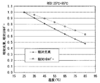
図3に、分光センサ19にて測定した赤LED光源1Rのオフ光15の分光スペクトルを示す。赤LED光源1Rの温度変化(25℃〜85℃)に伴って、分光スペクトルのピーク波長及びピーク強度が変化していることがわかる。図4に、図3の温度変化に対応した発光エネルギーと発光光束量(ルーメン値)の相対値を示す。温度変化により波長が変化しているため、発光エネルギーと発光光束量で変化の度合いが異なっている。また、図5は、図3に対応した色度図であり、温度変化により赤LED光源1Rの赤色光の色度が変化していることがわかる。
<Brightness and chromaticity correction>
FIG. 3 shows a spectral spectrum of the off-
以上のように、例えば、各プロジェクタ間において環境温度が異なると、各プロジェクタの光源の色度が変化するため、画面間において、輝度、色度の段差が生じる。輝度、色度の補正は、分光センサ19により測定した各光源(赤LED光源1R、緑LED光源1G、青LED光源1B)のオフ光15の分光スペクトルSR(λ),SG(λ),SB(λ)を基にして算出される3刺激値(X,Y,Z)が画面間で等しくなるように行われる。
As described above, for example, when the environmental temperature is different between the projectors, the chromaticity of the light source of each projector changes, so that there is a difference in luminance and chromaticity between the screens. Luminance and chromaticity are corrected by the spectral spectra S R (λ), S G (λ) of the off-
例えば、赤LED光源1Rのオフ光15の分光スペクトルSR(λ)に対応する3刺激値(XR,YR,ZR)は、式(1)により求められる。式(1)において、x(上バー)(λ),y(上バー)(λ),z(上バー)(λ)はXYZ表色系における等色関数であり(図6参照)、Kは定数である。また、緑LED光源1Gのオフ光15に対応する3刺激値(XG,YG,ZG)および青LED光源1Bのオフ光15に対応する3刺激値(XB,YB,ZB)は、式(1)において、SR(λ)をSG(λ)およびSB(λ)に置き換えることで求めることができる。ここで、SG(λ)、SB(λ)は、それぞれ緑LED光源1G、青LED光源1Bのオフ光15の分光スペクトルである。
For example, the tristimulus values (X R , Y R , Z R ) corresponding to the spectral spectrum S R (λ) of the off-

一般に、3刺激値(X,Y,Z)のうちYは輝度を表し、色度(x,y)は3刺激値を用いて、式(2)によって求められる。 In general, among tristimulus values (X, Y, Z), Y represents luminance, and chromaticity (x, y) is obtained by equation (2) using tristimulus values.
図7を用いて、第1のプロジェクタと第2のプロジェクタの2画面間の色度差の補正方法について説明する。図7の色度図において、R1,G1,B1を頂点とする、実線で囲んだ領域が第1のプロジェクタで表現可能な色度空間であり、R2,G2,B2を頂点とする、点線で囲んだ領域が第2のプロジェクタで表現可能な色度空間である。従って、R’,G’,B’を頂点とする共通の領域が、第1のプロジェクタでも第2のプロジェクタでも表現可能な色度空間である。よって、2つのプロジェクタの色度空間の各頂点を、共通領域の頂点(R’,G’,B’)に合わせるように補正を行えばよい。 A method of correcting the chromaticity difference between the two screens of the first projector and the second projector will be described with reference to FIG. In the chromaticity diagram of FIG. 7, a region surrounded by a solid line with vertices R 1 , G 1 , and B 1 is a chromaticity space that can be expressed by the first projector, and R 2 , G 2 , and B 2 are A region surrounded by a dotted line, which is a vertex, is a chromaticity space that can be expressed by the second projector. Therefore, a common area having R ′, G ′, and B ′ as vertices is a chromaticity space that can be expressed by both the first projector and the second projector. Therefore, correction may be performed so that the vertices of the chromaticity spaces of the two projectors are aligned with the vertices (R ′, G ′, B ′) of the common area.
以下では、第1のプロジェクタにおいて、赤LED光源1Rのオフ光15に対応する3刺激値をXR1,YR1,ZR1、緑LED光源1Gのオフ光15に対応する3刺激値をXG1,YG1,ZG1、青LED光源1Bのオフ光15に対応する3刺激値をXB1,YB1,ZB1と表記する。また、第2のプロジェクタにおける3刺激値は、第1のプロジェクタにおける3刺激値の下付部分において、1を2と置き換えて表記する。また、補正後の刺激値は、各刺激値にダッシュを付けた表記とする。例えば、第1のプロジェクタの赤LED光源1Rのオフ光15に対応する補正前の3刺激値は、XR1,YR1,ZR1であり、補正後の3刺激値は、X’R1,Y’R1,Z’R1と表記される。
In the following, in the first projector, the tristimulus values corresponding to the
第1のプロジェクタにおける、補正前後の3刺激値の関係は式(3)で表される。補正前後の3刺激値は、補正パラメータ(a,b,c,d,e,f,g,h,i)によって関連付けられている。 The relationship between the tristimulus values before and after correction in the first projector is expressed by Expression (3). Tristimulus values before and after correction are related by correction parameters (a, b, c, d, e, f, g, h, i).
式(4)は、第2のプロジェクタの補正前後の3刺激値の関係式である。補正前後の3刺激値は、補正パラメータ(j,k,l,m,n,o,p,q,r)によって関連付けられている。 Expression (4) is a relational expression of tristimulus values before and after correction of the second projector. Tristimulus values before and after correction are related by correction parameters (j, k, l, m, n, o, p, q, r).
2画面間の輝度、色度を等しくするためには、式(5)の関係が成り立てばよいので、この条件を満たすように、前述した補正パラメータ(a〜r)を決定すればよい。 In order to make the luminance and chromaticity between the two screens equal, the relationship of Expression (5) should be established, and the correction parameters (a to r) described above may be determined so as to satisfy this condition.
以上のようにして決定された補正パラメータに応じて補正を行って画像光を形成する。図2に示したように、DMDチップ11において、各光源の映像表示期間におけるオン光12とオフ光15の時間の割合を補正パラメータに基づいて変化させてPWM制御を行うことにより、補正が行われた画像光が投射される。
Image light is formed by performing correction according to the correction parameter determined as described above. As shown in FIG. 2, in the
なお、本実施の形態では、マルチ画面表示装置が2つのプロジェクタを備える場合について説明したが、プロジェクタの個数、即ち画面数が増えても同様の計算を行うことで画面間の輝度段差、色度段差の補正を行うことが可能である。 In this embodiment, the case where the multi-screen display device includes two projectors has been described. However, the same calculation is performed even when the number of projectors, that is, the number of screens is increased, so that the luminance level difference and chromaticity between the screens are increased. It is possible to correct the level difference.
また、本実施の形態では、光変調器としてDMDチップ11を使用したが、光変調器としての機能を備えるものであれば、これに限らない。
In this embodiment, the
また、本実施の形態では、光源として、LEDを用いたが、レーザーやランプなどを光源としてもよい。 In this embodiment, an LED is used as the light source, but a laser, a lamp, or the like may be used as the light source.
<効果>
本実施の形態におけるマルチ画像表示装置は、複数のプロジェクタの画面を組み合わせて一の画面を構成したマルチ画面表示装置であって、各プロジェクタは、光源と、光源から出力された光を照明光として照射する照明光学系と、照明光を変調して画像光を形成する光変調器と、画像光をスクリーン14に投射する投射光学系13とを備え、マルチ画面表示装置は、各プロジェクタにおける画像光の輝度と色度の変化を検出する少なくとも1つの分光センサ19を備える。
<Effect>
The multi-image display device according to the present embodiment is a multi-screen display device that combines a plurality of projector screens to form a single screen. Each projector uses a light source and light output from the light source as illumination light. An illumination optical system for irradiating, a light modulator that modulates illumination light to form image light, and a projection
従って、分光センサ19を使用して、単色光源ごとに分光スペクトルを測定することで、各光源の輝度、色度を精度良く検出することができるため、単色光源の波長が変化しても、画像光の輝度および色度を補正して、画面間の輝度段差および色度段差を低減することが可能である。また、分光センサ19はマルチ画面表示装置に内蔵されているので、補正を行うたびに使用者が分光センサを設置するなどの手間がかからず、従来と比較して使い勝手が向上する。
Therefore, by measuring the spectral spectrum for each monochromatic light source using the
また、本実施の形態におけるマルチ画面表示装置に備わる分光センサ19は、各プロジェクタごとに内蔵されることを特徴とする。従って、各プロジェクタごとに分光センサ19を内蔵することで、分光センサ19に入力されるオフ光15の経路を短くできるので、プロジェクタの構成を簡素化することができる。
Further, the
また、本実施の形態におけるマルチ画面表示装置に備わる光変調器はDMDチップ11であり、分光センサ19は、DMDチップ11のオフ光15を検出することを特徴とする。従って、光変調器としてDMDチップ11を使用したことにより、オフ光15を利用して補正を行うことが可能となるので、スクリーン14に画像を投射中であっても、補正を行うことが可能である。よって、映像表示中に補正が必要となっても、補正を行うために映像表示を中断する必要がないので、使用者の使い勝手を向上させることができる。
Further, the optical modulator provided in the multi-screen display device in the present embodiment is the
<実施の形態2>
本実施の形態におけるマルチ画面表示装置は、図8に示すように、4つのプロジェクタ20A,20B,20C,20Dを備え、マルチ画面表示装置に内蔵される分光センサ19は、各プロジェクタ間で共有されている。
<
As shown in FIG. 8, the multi-screen display device in the present embodiment includes four
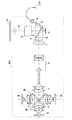
本実施の形態におけるプロジェクタ20Aの構成を図9に示す。また、プロジェクタ20B,20C,20Dの構成は、プロジェクタ20Aと同じである。なお、各プロジェクタの映像投射装置としての基本的な構成、動作は、実施の形態1と同じであるので、説明を省略する。
FIG. 9 shows the configuration of
各プロジェクタにおけるDMDチップ11のオフ光15は、それぞれ光ファイバー21A,21B,21C,21Dによってプロジェクタから引き出され、シャッター22(後述)および光線を平行化するコリメートレンズ23を介して、分光センサ19に入力される。なお分光センサ19の構成、機能は実施の形態1と同じであるので、説明を省略する。
The off-
図9に示す様に、プロジェクタ20Aにおいて、DMDチップ11のオフ光15は、コンデンサレンズ24により光ファイバー21Aの入射端に集光され、光ファイバー21Aに取り込まれる。
As shown in FIG. 9, in the
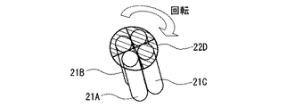
各プロジェクタ20A,20B,20C,20D内で光ファイバー21A,21B,21C,21Dに取り込まれた各プロジェクタのオフ光15は、シャッター22によって、分光センサ19で測定する光線のみ透過するように切り替えられる。シャッター22は、例えば図10に示すように、1本の光ファイバー分だけ開口が形成され、回転して各光ファイバーを選択可能な部材で構成される。このように、シャッター22を順に切り替えることによって、各プロジェクタにおける分光スペクトルデータを順に取得することができる。
The off light 15 of each projector taken into the
なお、本実施の形態のマルチ画像表示装置は4つのプロジェクタの画面、即ち4画面で画面を構成したが、2画面以上であれば、これに限定するものではない。 Note that the multi-image display apparatus according to the present embodiment has four projector screens, that is, four screens, but the screen is not limited to this as long as there are two or more screens.
<効果>
本実施の形態におけるマルチ画面表示装置において、分光センサ19は、プロジェクタ20A,20B,20C,20D間で共有され、1つのみ設けられることを特徴とする。従って、実施の形態1の効果で述べたように、分光センサ19を使用することで、精度良く輝度、色度を検出して補正を行う効果に加えて、1つの分光センサ19を、複数のプロジェクタで共有して使用するので、実施の形態1と比較して、使用する分光センサの個数を減らすことが可能である。よって、構成部品数を減らすことができるため、製造コスト削減が期待できる。
<Effect>
In the multi-screen display device according to the present embodiment, the
<実施の形態3>
本実施の形態におけるマルチ画面表示装置は、実施の形態1と同じく2つのプロジェクタ(第1のプロジェクタ、第2のプロジェクタ)を備える。第1のプロジェクタの構成を図11に示す。本実施の形態におけるプロジェクタの構成は、実施の形態1のプロジェクタの構成(図1)に加えて、光ファイバーを以下の様に配設した点が異なる。即ち、光ファイバー25A,25B,25C,25D,25E,25F,25Gはそれぞれ、赤LED光源1Rの光、緑LED光源1Gの光、青LED光源1Bの光、インテグレータ5に入射する光、インテグレータ5から出射する光、DMDチップ11に入射する光、スクリーン14面に投影される光を取り込むように配設されている。
<Embodiment 3>
The multi-screen display device in the present embodiment includes two projectors (a first projector and a second projector) as in the first embodiment. FIG. 11 shows the configuration of the first projector. The configuration of the projector according to the present embodiment is different from the configuration of the projector according to the first embodiment (FIG. 1) in that optical fibers are arranged as follows. That is, the
これらの光ファイバーに取り込まれた光は、オフ光15と併せて、シャッター22およびコリメートレンズ23を介して、分光センサ19へ入力される。ここで、シャッター22は、実施の形態2(図10)で説明したシャッター22と同様の構造とする。ただし、シャッター22に入力される光線の数は異なる。なお、第2のプロジェクタの構成も第1のプロジェクタの構成と同じである。
The light taken into these optical fibers is input to the
このように各光ファイバーの光線およびオフ光15の分光スペクトルを、シャッター22を切り替えることで順番に測定することができる。測定した分光スペクトルを比べることにより、光源や、光学部品、光学系の劣化度を測定することが可能となる。ただし、光ファイバー25A〜25Fは常時測定可能であるが、スクリーン14面に投射される光を取り込む光ファイバー25Gのみ、測定時に測定専用の信号を出力する必要がある。
In this way, the light spectrum of each optical fiber and the spectral spectrum of the off-light 15 can be sequentially measured by switching the
例えば、赤LED光源1Rの初期の分光スペクトルをSR0(λ)、使用後の分光スペクトルをSR(λ)とすると、赤LED光源1Rの使用による劣化度は、式(6)で測定できる。
For example, when the initial spectral spectrum of the red LED
![]()
![]()
式(6)が1を下回る場合、劣化が起こっていると考えられ、式(6)の値に基づいて、光源の交換等のメンテナンス情報を表示して使用者に知らせることが可能となる。 When the expression (6) is less than 1, it is considered that the deterioration has occurred, and based on the value of the expression (6), maintenance information such as replacement of the light source can be displayed to notify the user.
例えば、インテグレータ5の劣化度を測定する場合、インテグレータ5に入射する光の初期の分光スペクトルをS25D0(λ)、使用後の分光スペクトルをS25D(λ)とすると、インテグレータ5に入射する光の減衰は、式(7)で求められる。
For example, when measuring the degree of deterioration of the
![]()
![]()
また、インテグレータ5の出射光の初期の分光スペクトルをS25E0(λ)、使用後の分光スペクトルをS25E(λ)とすると、インテグレータ5の出射光の減衰は、式(8)で求められる。
Further, assuming that the initial spectral spectrum of the light emitted from the
![]()
![]()
式(9)のように、式(7)と式(8)の減衰率の比を求めることで、インテグレータ5の劣化度を求めることができる。
As in equation (9), the deterioration degree of the
式(9)が1であれば、インテグレータ5に劣化なし、1を下回っていれば、劣化ありを意味する。その劣化度から、インテグレータ5の交換、清掃等のタイミングを判断可能となる。
If the expression (9) is 1, it means that there is no deterioration in the
このように、任意の箇所、即ち、光源や照明光学系や投射光学系等の前後、インテグレータ等の光学機器の前後等において、光のスペクトルを測定することで、その光学系や光学部品の劣化度を調べることが可能である。 In this way, by measuring the spectrum of light at any location, that is, before and after the light source, illumination optical system, projection optical system, etc., before and after optical equipment such as an integrator, the optical system and optical components deteriorate. It is possible to check the degree.
<効果>
本実施の形態におけるマルチ画面表示装置は、光源での光、照明光学系での光、光変調器での光、投射光学系での光の複数個を分光センサ19に入力し、比較することを特徴とする。従って、実施の形態1で述べた効果に加えて、分光センサ19を利用して、光源や光学部品、光学系の劣化等を検出することが可能である。
<Effect>
The multi-screen display device in the present embodiment inputs a plurality of light from a light source, light from an illumination optical system, light from an optical modulator, and light from a projection optical system to the
<実施の形態4>
図12に、本実施の形態におけるマルチ画面表示装置の構成を示す。本実施の形態において、実施の形態2(図8)と異なるのは、各プロジェクタ20A,20B,20C,20D間において、光源、即ち赤LED光源1R、緑LED光源1G、青LED光源1Bが共有されている点である。それ以外は実施の形態2と同じであるので、説明を省略する。
<
FIG. 12 shows the configuration of the multi-screen display device in this embodiment. This embodiment differs from the second embodiment (FIG. 8) in that the light sources, that is, the red LED
図12において、赤LED光源1R、緑LED光源1G、青LED光源1Bから発せられる各色光は、コリメートレンズ2及びコンデンサレンズ4を介して、それぞれ、赤LED光源用光ファイバー束26a、緑LED光源用光ファイバー束27a、青LED光源用光ファイバー束28aのファイバー端へ集光される。
In FIG. 12, each color light emitted from the red LED
光ファイバー束26a,27a,28aにより分配されて各色光を取り込んだ光ファイバー26,27,28は、各プロジェクタ20A,20B,20C,20Dおよび、分光センサ19のシャッター22へ、図2のように接続される。
The
図13に、プロジェクタ20Aの構成を示す。実施の形態2(図9)と異なるのは、プロジェクタ20Aの光源が、プロジェクタ20Aに内蔵されない点である。光源からの各色光を伝送する光ファイバー26,27,28は、インテグレータ5の入射面に接続される。他は実施の形態2と同じであるので、説明を省略する。また、他のプロジェクタ20B,20C,20Dの構成もプロジェクタ20Aと同じである。
FIG. 13 shows the configuration of the
また、各光源からの光ファイバー26、27、28を分光センサ19にも接続することで、実施の形態3のように、光源の劣化等を調べることが可能である。
Further, by connecting the
なお、本実施の形態において、分配する光源は、赤LED光源1R、緑LED光源1G、青LED光源1B各1個でなく、複数個ずつでも、各プロジェクタ20A,20B,20C,20Dに均等に分配されればよい。
In the present embodiment, the light source to be distributed is not equal to each of the red LED
<効果>
本実施の形態におけるマルチ画面表示装置は、実施の形態2のように各プロジェクタごとに備えられる光源に代えて、各プロジェクタ20A,20B,20C,20D間で共有される光源を備えることを特徴とする。従って、実施の形態2で述べた効果に加えて、例えば、光源の発光強度が高い場合には、その光源を各プロジェクタで共有することで、光源の利用効率を向上させることが可能である。また、光源を共有することで、使用する光源の個数を削減することが可能であり、製造コスト削減が期待できる。
<Effect>
The multi-screen display device according to the present embodiment includes a light source shared between the
なお、本発明は、その発明の範囲内において、各実施の形態を自由に組み合わせたり、各実施の形態を適宜、変形、省略することが可能である。 It should be noted that the present invention can be freely combined with each other within the scope of the invention, and each embodiment can be appropriately modified or omitted.
1R 赤LED光源、1G 緑LED光源、1B 青LED光源、2,23 コリメートレンズ、3R、3B ダイクロイックミラー、4,24 コンデンサレンズ、5 インテグレータ、6 リレーレンズ群、7 フィールドレンズ、8 内部全反射プリズム、9 内部全反射面、10 照明光、11 DMDチップ、12 オン光、13 投射光学系、14 スクリーン、15 オフ光、16 回折格子、17 分光、18 ラインセンサ、19 分光センサ、20A,20B,20C,20D プロジェクタ、21A,21B,21C,21D,25A,25B,25C,25D,25E,25F,25G,26,27,28 光ファイバー、22 シャッター、26a,27a,28a 光ファイバー束。 1R red LED light source, 1G green LED light source, 1B blue LED light source, 2,23 collimating lens, 3R, 3B dichroic mirror, 4,24 condenser lens, 5 integrator, 6 relay lens group, 7 field lens, 8 internal total reflection prism , 9 Internal total reflection surface, 10 Illumination light, 11 DMD chip, 12 On light, 13 Projection optical system, 14 Screen, 15 Off light, 16 Diffraction grating, 17 Spectroscopy, 18 Line sensor, 19 Spectroscopic sensor, 20A, 20B, 20C, 20D Projector, 21A, 21B, 21C, 21D, 25A, 25B, 25C, 25D, 25E, 25F, 25G, 26, 27, 28 Optical fiber, 22 Shutter, 26a, 27a, 28a Optical fiber bundle.
Claims (6)
各前記プロジェクタは、
光源と、
前記光源から出力された光を照明光として照射する照明光学系と、
前記照明光を変調して画像光を形成する光変調器と、
前記画像光をスクリーンに投射する投射光学系と、
を備え、
前記マルチ画面表示装置は、各前記プロジェクタにおける前記画像光の輝度と色度の変化を検出する少なくとも1つの分光センサを備える、
マルチ画面表示装置。 A multi-screen display device that combines a plurality of projector screens to form a single screen,
Each of the projectors
A light source;
An illumination optical system for illuminating the light output from the light source as illumination light;
A light modulator that modulates the illumination light to form image light;
A projection optical system for projecting the image light onto a screen;
With
The multi-screen display device includes at least one spectroscopic sensor that detects a change in luminance and chromaticity of the image light in each projector.
Multi-screen display device.
請求項1に記載のマルチ画面表示装置。 The spectroscopic sensor is built in each projector.
The multi-screen display device according to claim 1.
請求項1に記載のマルチ画面表示装置。 The spectral sensor is shared between the projectors, and only one is provided.
The multi-screen display device according to claim 1.
請求項1〜3に記載のマルチ画面表示装置。 The light modulator is a DMD chip, and the spectroscopic sensor detects off-light of the DMD chip.
The multi-screen display device according to claim 1.
請求項1〜4のいずれかに記載のマルチ画面表示装置。 A plurality of light from the light source, light from the illumination optical system, light from the light modulator, and light from the projection optical system are input to the spectroscopic sensor for comparison.
The multi-screen display device according to claim 1.
請求項1〜5のいずれかに記載のマルチ画面表示装置。 In place of the light source provided for each projector, a light source shared between the projectors,
The multi-screen display device according to claim 1.
Priority Applications (3)
| Application Number | Priority Date | Filing Date | Title |
|---|---|---|---|
| JP2012046190A JP2013182142A (en) | 2012-03-02 | 2012-03-02 | Multi-screen display device |
| US13/721,175 US20130229629A1 (en) | 2012-03-02 | 2012-12-20 | Multi-screen display device |
| CN2013100469842A CN103297734A (en) | 2012-03-02 | 2013-02-06 | Multi-screen display device |
Applications Claiming Priority (1)
| Application Number | Priority Date | Filing Date | Title |
|---|---|---|---|
| JP2012046190A JP2013182142A (en) | 2012-03-02 | 2012-03-02 | Multi-screen display device |
Publications (2)
| Publication Number | Publication Date |
|---|---|
| JP2013182142A true JP2013182142A (en) | 2013-09-12 |
| JP2013182142A5 JP2013182142A5 (en) | 2015-02-19 |
Family
ID=49042677
Family Applications (1)
| Application Number | Title | Priority Date | Filing Date |
|---|---|---|---|
| JP2012046190A Pending JP2013182142A (en) | 2012-03-02 | 2012-03-02 | Multi-screen display device |
Country Status (3)
| Country | Link |
|---|---|
| US (1) | US20130229629A1 (en) |
| JP (1) | JP2013182142A (en) |
| CN (1) | CN103297734A (en) |
Families Citing this family (14)
| Publication number | Priority date | Publication date | Assignee | Title |
|---|---|---|---|---|
| JP6425110B2 (en) * | 2013-01-30 | 2018-11-21 | ウシオ電機株式会社 | Light source device and projector |
| WO2014136882A1 (en) * | 2013-03-06 | 2014-09-12 | ウシオ電機株式会社 | Light source device and projector |
| US20140327750A1 (en) * | 2013-05-01 | 2014-11-06 | Nvidia Corporation | System, method, and computer program product for displaying a scene as a light field |
| CN104880890A (en) * | 2014-02-27 | 2015-09-02 | 中强光电股份有限公司 | Projection apparatus and brightness modulating method thereof |
| GB201415632D0 (en) * | 2014-09-04 | 2014-10-22 | Bae Systems Plc | Improvements in and relating to displays |
| TW201710113A (en) * | 2015-06-02 | 2017-03-16 | 康寧公司 | Vehicle projection system |
| WO2017094690A1 (en) * | 2015-12-04 | 2017-06-08 | コニカミノルタ株式会社 | Projection-type display device and design method therefor |
| CN108076330B (en) * | 2016-11-17 | 2019-09-20 | 深圳光峰科技股份有限公司 | Projection display apparatus |
| US10785459B2 (en) * | 2018-01-19 | 2020-09-22 | Texas Instruments Incorporated | DLP color projector |
| JP2019154002A (en) * | 2018-03-06 | 2019-09-12 | キヤノン株式会社 | Control device, control method thereof, projection device, and projection system |
| CN108459456A (en) * | 2018-04-28 | 2018-08-28 | 青岛海信激光显示股份有限公司 | A kind of light fixture and laser projection device applied in laser projection device |
| US20220256130A1 (en) * | 2019-04-02 | 2022-08-11 | Ningbo Sunny Automotive Optech Co., Ltd. | Projection adjustment system and method, and projection color adjustment system and method |
| CN111768731B (en) * | 2019-04-02 | 2022-11-11 | 宁波舜宇车载光学技术有限公司 | Projection color adjusting system and method thereof |
| CN111830772B (en) * | 2019-04-18 | 2022-10-21 | 青岛海信激光显示股份有限公司 | Laser projection device and control method thereof |
Citations (7)
| Publication number | Priority date | Publication date | Assignee | Title |
|---|---|---|---|---|
| JPH05232428A (en) * | 1992-02-19 | 1993-09-10 | Sanyo Electric Co Ltd | Projection type liquid crystal display device |
| JP2000148075A (en) * | 1998-11-10 | 2000-05-26 | Nec Corp | System and method for correcting color, and multi- projector system |
| JP2000193914A (en) * | 1998-12-28 | 2000-07-14 | Texas Instr Inc <Ti> | Adaptive temporal modulation on light source periodically varying |
| JP2000214529A (en) * | 1999-01-20 | 2000-08-04 | Ldt Gmbh & Co Laser Display Technol Kg | Video projecting system for projecting plural pictures |
| JP2005141043A (en) * | 2003-11-07 | 2005-06-02 | Fujitsu Ltd | Image display apparatus |
| JP2008299063A (en) * | 2007-05-31 | 2008-12-11 | Sanyo Electric Co Ltd | Projection image display |
| WO2009142015A1 (en) * | 2008-05-21 | 2009-11-26 | パナソニック株式会社 | Projector |
Family Cites Families (11)
| Publication number | Priority date | Publication date | Assignee | Title |
|---|---|---|---|---|
| US6456339B1 (en) * | 1998-07-31 | 2002-09-24 | Massachusetts Institute Of Technology | Super-resolution display |
| JP3497805B2 (en) * | 2000-08-29 | 2004-02-16 | オリンパス株式会社 | Image projection display device |
| US6771326B2 (en) * | 2000-10-26 | 2004-08-03 | General Atomics, Inc. | Multi-screen laser projection system using a shared laser source |
| JP4501481B2 (en) * | 2004-03-22 | 2010-07-14 | セイコーエプソン株式会社 | Image correction method for multi-projection system |
| US20070091434A1 (en) * | 2005-10-21 | 2007-04-26 | Hewlett-Packard Development Company, L.P. | Luminance adjustment |
| NO330155B1 (en) * | 2006-02-28 | 2011-02-28 | 3D Perception As | Method and apparatus for use in calibrating a projector's image display to a display screen, and display screen for such use. |
| JP5055997B2 (en) * | 2006-12-14 | 2012-10-24 | パナソニック株式会社 | Multi-screen display device and display image adjustment method |
| JP2010219164A (en) * | 2009-03-13 | 2010-09-30 | Omron Corp | Method of detecting damage to optical element |
| JP5625287B2 (en) * | 2009-08-21 | 2014-11-19 | カシオ計算機株式会社 | Light source device, projection device, projection method and program |
| JP2011154174A (en) * | 2010-01-27 | 2011-08-11 | Mitsubishi Electric Corp | Multi-screen display device |
| JP5609611B2 (en) * | 2010-03-11 | 2014-10-22 | 株式会社リコー | Spectral characteristic acquisition device, image evaluation device, and image forming device |
-
2012
- 2012-03-02 JP JP2012046190A patent/JP2013182142A/en active Pending
- 2012-12-20 US US13/721,175 patent/US20130229629A1/en not_active Abandoned
-
2013
- 2013-02-06 CN CN2013100469842A patent/CN103297734A/en active Pending
Patent Citations (7)
| Publication number | Priority date | Publication date | Assignee | Title |
|---|---|---|---|---|
| JPH05232428A (en) * | 1992-02-19 | 1993-09-10 | Sanyo Electric Co Ltd | Projection type liquid crystal display device |
| JP2000148075A (en) * | 1998-11-10 | 2000-05-26 | Nec Corp | System and method for correcting color, and multi- projector system |
| JP2000193914A (en) * | 1998-12-28 | 2000-07-14 | Texas Instr Inc <Ti> | Adaptive temporal modulation on light source periodically varying |
| JP2000214529A (en) * | 1999-01-20 | 2000-08-04 | Ldt Gmbh & Co Laser Display Technol Kg | Video projecting system for projecting plural pictures |
| JP2005141043A (en) * | 2003-11-07 | 2005-06-02 | Fujitsu Ltd | Image display apparatus |
| JP2008299063A (en) * | 2007-05-31 | 2008-12-11 | Sanyo Electric Co Ltd | Projection image display |
| WO2009142015A1 (en) * | 2008-05-21 | 2009-11-26 | パナソニック株式会社 | Projector |
Also Published As
| Publication number | Publication date |
|---|---|
| CN103297734A (en) | 2013-09-11 |
| US20130229629A1 (en) | 2013-09-05 |
Similar Documents
| Publication | Publication Date | Title |
|---|---|---|
| JP2013182142A (en) | Multi-screen display device | |
| JP6406739B2 (en) | LIGHTING DEVICE, PROJECTOR, DISPLAY SYSTEM, AND LIGHT SOURCE ADJUSTING METHOD | |
| EP2506573A2 (en) | Projection display apparatus, projection display method and computer-readable storage medium | |
| JP6519970B2 (en) | Image display apparatus, projector and control method thereof | |
| TWI446095B (en) | Projecting device, projecting method and program | |
| JP2013182142A5 (en) | ||
| JP5729522B2 (en) | Light source device and projector | |
| US10674122B2 (en) | Light source unit and projection-type display | |
| JP5900806B2 (en) | Light source device and projector | |
| KR101185297B1 (en) | Projector | |
| US10928250B2 (en) | Projector, color correction system, and control method for projector | |
| JP2015079208A (en) | Image display device and control method | |
| JP2008160441A (en) | Projector | |
| US10855962B2 (en) | Projector, color correction system, and control method of projector | |
| US20210302821A1 (en) | Light source apparatus and projector | |
| JP7472718B2 (en) | Calibration device, calibration method, and calibration program | |
| JP2014187465A (en) | Light source device and projector | |
| JP5755488B2 (en) | Projection-type image display device and multi-vision projection-type image display device | |
| JP2016061866A (en) | Light source device and projector | |
| JP5880496B2 (en) | Light source device and projector | |
| JP2015152639A (en) | display device and light source device | |
| JP2016128871A (en) | Light source device and projection type display device | |
| JP6300129B2 (en) | Light source device and projector | |
| JP2018061149A (en) | Image projection device | |
| JP2006098374A (en) | Chromaticity-measuring technique and chromaticity-measuring device |
Legal Events
| Date | Code | Title | Description |
|---|---|---|---|
| A521 | Request for written amendment filed |
Free format text: JAPANESE INTERMEDIATE CODE: A523 Effective date: 20141219 |
|
| A621 | Written request for application examination |
Free format text: JAPANESE INTERMEDIATE CODE: A621 Effective date: 20141219 |
|
| A977 | Report on retrieval |
Free format text: JAPANESE INTERMEDIATE CODE: A971007 Effective date: 20151023 |
|
| A131 | Notification of reasons for refusal |
Free format text: JAPANESE INTERMEDIATE CODE: A131 Effective date: 20151110 |
|
| A02 | Decision of refusal |
Free format text: JAPANESE INTERMEDIATE CODE: A02 Effective date: 20160315 |