JP2013085363A - Battery state management device, battery state management method - Google Patents
Battery state management device, battery state management method Download PDFInfo
- Publication number
- JP2013085363A JP2013085363A JP2011223167A JP2011223167A JP2013085363A JP 2013085363 A JP2013085363 A JP 2013085363A JP 2011223167 A JP2011223167 A JP 2011223167A JP 2011223167 A JP2011223167 A JP 2011223167A JP 2013085363 A JP2013085363 A JP 2013085363A
- Authority
- JP
- Japan
- Prior art keywords
- battery
- state management
- monitoring device
- management device
- battery monitoring
- Prior art date
- Legal status (The legal status is an assumption and is not a legal conclusion. Google has not performed a legal analysis and makes no representation as to the accuracy of the status listed.)
- Pending
Links
Images


Classifications
-
- H—ELECTRICITY
- H02—GENERATION; CONVERSION OR DISTRIBUTION OF ELECTRIC POWER
- H02J—CIRCUIT ARRANGEMENTS OR SYSTEMS FOR SUPPLYING OR DISTRIBUTING ELECTRIC POWER; SYSTEMS FOR STORING ELECTRIC ENERGY
- H02J7/00—Circuit arrangements for charging or depolarising batteries or for supplying loads from batteries
- H02J7/0013—Circuit arrangements for charging or depolarising batteries or for supplying loads from batteries acting upon several batteries simultaneously or sequentially
- H02J7/0014—Circuits for equalisation of charge between batteries
- H02J7/0016—Circuits for equalisation of charge between batteries using shunting, discharge or bypass circuits
-
- H—ELECTRICITY
- H01—ELECTRIC ELEMENTS
- H01M—PROCESSES OR MEANS, e.g. BATTERIES, FOR THE DIRECT CONVERSION OF CHEMICAL ENERGY INTO ELECTRICAL ENERGY
- H01M10/00—Secondary cells; Manufacture thereof
- H01M10/42—Methods or arrangements for servicing or maintenance of secondary cells or secondary half-cells
- H01M10/48—Accumulators combined with arrangements for measuring, testing or indicating the condition of cells, e.g. the level or density of the electrolyte
-
- B—PERFORMING OPERATIONS; TRANSPORTING
- B60—VEHICLES IN GENERAL
- B60L—PROPULSION OF ELECTRICALLY-PROPELLED VEHICLES; SUPPLYING ELECTRIC POWER FOR AUXILIARY EQUIPMENT OF ELECTRICALLY-PROPELLED VEHICLES; ELECTRODYNAMIC BRAKE SYSTEMS FOR VEHICLES IN GENERAL; MAGNETIC SUSPENSION OR LEVITATION FOR VEHICLES; MONITORING OPERATING VARIABLES OF ELECTRICALLY-PROPELLED VEHICLES; ELECTRIC SAFETY DEVICES FOR ELECTRICALLY-PROPELLED VEHICLES
- B60L50/00—Electric propulsion with power supplied within the vehicle
- B60L50/50—Electric propulsion with power supplied within the vehicle using propulsion power supplied by batteries or fuel cells
- B60L50/51—Electric propulsion with power supplied within the vehicle using propulsion power supplied by batteries or fuel cells characterised by AC-motors
-
- B—PERFORMING OPERATIONS; TRANSPORTING
- B60—VEHICLES IN GENERAL
- B60L—PROPULSION OF ELECTRICALLY-PROPELLED VEHICLES; SUPPLYING ELECTRIC POWER FOR AUXILIARY EQUIPMENT OF ELECTRICALLY-PROPELLED VEHICLES; ELECTRODYNAMIC BRAKE SYSTEMS FOR VEHICLES IN GENERAL; MAGNETIC SUSPENSION OR LEVITATION FOR VEHICLES; MONITORING OPERATING VARIABLES OF ELECTRICALLY-PROPELLED VEHICLES; ELECTRIC SAFETY DEVICES FOR ELECTRICALLY-PROPELLED VEHICLES
- B60L58/00—Methods or circuit arrangements for monitoring or controlling batteries or fuel cells, specially adapted for electric vehicles
- B60L58/10—Methods or circuit arrangements for monitoring or controlling batteries or fuel cells, specially adapted for electric vehicles for monitoring or controlling batteries
- B60L58/18—Methods or circuit arrangements for monitoring or controlling batteries or fuel cells, specially adapted for electric vehicles for monitoring or controlling batteries of two or more battery modules
- B60L58/21—Methods or circuit arrangements for monitoring or controlling batteries or fuel cells, specially adapted for electric vehicles for monitoring or controlling batteries of two or more battery modules having the same nominal voltage
-
- B—PERFORMING OPERATIONS; TRANSPORTING
- B60—VEHICLES IN GENERAL
- B60L—PROPULSION OF ELECTRICALLY-PROPELLED VEHICLES; SUPPLYING ELECTRIC POWER FOR AUXILIARY EQUIPMENT OF ELECTRICALLY-PROPELLED VEHICLES; ELECTRODYNAMIC BRAKE SYSTEMS FOR VEHICLES IN GENERAL; MAGNETIC SUSPENSION OR LEVITATION FOR VEHICLES; MONITORING OPERATING VARIABLES OF ELECTRICALLY-PROPELLED VEHICLES; ELECTRIC SAFETY DEVICES FOR ELECTRICALLY-PROPELLED VEHICLES
- B60L58/00—Methods or circuit arrangements for monitoring or controlling batteries or fuel cells, specially adapted for electric vehicles
- B60L58/10—Methods or circuit arrangements for monitoring or controlling batteries or fuel cells, specially adapted for electric vehicles for monitoring or controlling batteries
- B60L58/18—Methods or circuit arrangements for monitoring or controlling batteries or fuel cells, specially adapted for electric vehicles for monitoring or controlling batteries of two or more battery modules
- B60L58/22—Balancing the charge of battery modules
-
- H—ELECTRICITY
- H01—ELECTRIC ELEMENTS
- H01M—PROCESSES OR MEANS, e.g. BATTERIES, FOR THE DIRECT CONVERSION OF CHEMICAL ENERGY INTO ELECTRICAL ENERGY
- H01M10/00—Secondary cells; Manufacture thereof
- H01M10/42—Methods or arrangements for servicing or maintenance of secondary cells or secondary half-cells
- H01M10/44—Methods for charging or discharging
-
- B—PERFORMING OPERATIONS; TRANSPORTING
- B60—VEHICLES IN GENERAL
- B60L—PROPULSION OF ELECTRICALLY-PROPELLED VEHICLES; SUPPLYING ELECTRIC POWER FOR AUXILIARY EQUIPMENT OF ELECTRICALLY-PROPELLED VEHICLES; ELECTRODYNAMIC BRAKE SYSTEMS FOR VEHICLES IN GENERAL; MAGNETIC SUSPENSION OR LEVITATION FOR VEHICLES; MONITORING OPERATING VARIABLES OF ELECTRICALLY-PROPELLED VEHICLES; ELECTRIC SAFETY DEVICES FOR ELECTRICALLY-PROPELLED VEHICLES
- B60L2240/00—Control parameters of input or output; Target parameters
- B60L2240/40—Drive Train control parameters
- B60L2240/54—Drive Train control parameters related to batteries
- B60L2240/545—Temperature
-
- B—PERFORMING OPERATIONS; TRANSPORTING
- B60—VEHICLES IN GENERAL
- B60L—PROPULSION OF ELECTRICALLY-PROPELLED VEHICLES; SUPPLYING ELECTRIC POWER FOR AUXILIARY EQUIPMENT OF ELECTRICALLY-PROPELLED VEHICLES; ELECTRODYNAMIC BRAKE SYSTEMS FOR VEHICLES IN GENERAL; MAGNETIC SUSPENSION OR LEVITATION FOR VEHICLES; MONITORING OPERATING VARIABLES OF ELECTRICALLY-PROPELLED VEHICLES; ELECTRIC SAFETY DEVICES FOR ELECTRICALLY-PROPELLED VEHICLES
- B60L2240/00—Control parameters of input or output; Target parameters
- B60L2240/40—Drive Train control parameters
- B60L2240/54—Drive Train control parameters related to batteries
- B60L2240/547—Voltage
-
- B—PERFORMING OPERATIONS; TRANSPORTING
- B60—VEHICLES IN GENERAL
- B60L—PROPULSION OF ELECTRICALLY-PROPELLED VEHICLES; SUPPLYING ELECTRIC POWER FOR AUXILIARY EQUIPMENT OF ELECTRICALLY-PROPELLED VEHICLES; ELECTRODYNAMIC BRAKE SYSTEMS FOR VEHICLES IN GENERAL; MAGNETIC SUSPENSION OR LEVITATION FOR VEHICLES; MONITORING OPERATING VARIABLES OF ELECTRICALLY-PROPELLED VEHICLES; ELECTRIC SAFETY DEVICES FOR ELECTRICALLY-PROPELLED VEHICLES
- B60L2240/00—Control parameters of input or output; Target parameters
- B60L2240/40—Drive Train control parameters
- B60L2240/54—Drive Train control parameters related to batteries
- B60L2240/549—Current
-
- Y—GENERAL TAGGING OF NEW TECHNOLOGICAL DEVELOPMENTS; GENERAL TAGGING OF CROSS-SECTIONAL TECHNOLOGIES SPANNING OVER SEVERAL SECTIONS OF THE IPC; TECHNICAL SUBJECTS COVERED BY FORMER USPC CROSS-REFERENCE ART COLLECTIONS [XRACs] AND DIGESTS
- Y02—TECHNOLOGIES OR APPLICATIONS FOR MITIGATION OR ADAPTATION AGAINST CLIMATE CHANGE
- Y02E—REDUCTION OF GREENHOUSE GAS [GHG] EMISSIONS, RELATED TO ENERGY GENERATION, TRANSMISSION OR DISTRIBUTION
- Y02E60/00—Enabling technologies; Technologies with a potential or indirect contribution to GHG emissions mitigation
- Y02E60/10—Energy storage using batteries
-
- Y—GENERAL TAGGING OF NEW TECHNOLOGICAL DEVELOPMENTS; GENERAL TAGGING OF CROSS-SECTIONAL TECHNOLOGIES SPANNING OVER SEVERAL SECTIONS OF THE IPC; TECHNICAL SUBJECTS COVERED BY FORMER USPC CROSS-REFERENCE ART COLLECTIONS [XRACs] AND DIGESTS
- Y02—TECHNOLOGIES OR APPLICATIONS FOR MITIGATION OR ADAPTATION AGAINST CLIMATE CHANGE
- Y02T—CLIMATE CHANGE MITIGATION TECHNOLOGIES RELATED TO TRANSPORTATION
- Y02T10/00—Road transport of goods or passengers
- Y02T10/60—Other road transportation technologies with climate change mitigation effect
- Y02T10/70—Energy storage systems for electromobility, e.g. batteries
-
- Y—GENERAL TAGGING OF NEW TECHNOLOGICAL DEVELOPMENTS; GENERAL TAGGING OF CROSS-SECTIONAL TECHNOLOGIES SPANNING OVER SEVERAL SECTIONS OF THE IPC; TECHNICAL SUBJECTS COVERED BY FORMER USPC CROSS-REFERENCE ART COLLECTIONS [XRACs] AND DIGESTS
- Y02—TECHNOLOGIES OR APPLICATIONS FOR MITIGATION OR ADAPTATION AGAINST CLIMATE CHANGE
- Y02T—CLIMATE CHANGE MITIGATION TECHNOLOGIES RELATED TO TRANSPORTATION
- Y02T90/00—Enabling technologies or technologies with a potential or indirect contribution to GHG emissions mitigation
- Y02T90/10—Technologies relating to charging of electric vehicles
- Y02T90/16—Information or communication technologies improving the operation of electric vehicles
Abstract
Description
本発明は、電池状態管理装置および電池状態管理方法に関する。 The present invention relates to a battery state management device and a battery state management method.
従来、管理ユニットから無線送信される指示信号に応じて、起動回路によりスイッチをオンして電池情報取得回路や無線回路を起動させ、電池情報取得回路により取得した電池情報を無線回路から管理ユニットへ無線送信する電池情報管理システムが知られている(特許文献1参照)。 Conventionally, in response to an instruction signal transmitted wirelessly from the management unit, the activation circuit turns on the switch to activate the battery information acquisition circuit or the wireless circuit, and the battery information acquired by the battery information acquisition circuit is transferred from the wireless circuit to the management unit. A battery information management system for wireless transmission is known (see Patent Document 1).
しかしながら、上記特許文献1に記載のシステムでは、管理ユニットが動作していないときには電池情報を取得できないため、車両等に組み込まれる前の段階で行う電池状態の管理において用いるのには不十分であった。
However, since the battery information cannot be acquired when the management unit is not operating in the system described in
本発明による電池状態管理装置は、1つまたは直列接続された複数の電池セルによってそれぞれ構成される1つまたは複数の電池セルグループが直列接続されて構成された電池の状態を管理するものであって、電池セルグループは、電池の状態を電池セルグループごとにそれぞれ監視して監視結果を電池状態管理装置へ無線送信するように構成されている電池監視装置と接続されており、電池監視装置は、電池状態管理装置が正当な通信先であるか否かを判定するための認証を行う認証回路を備え、認証回路により電池状態管理装置が正当な通信先であると判定された場合、電池監視装置は、接続されている電池セルグループの監視結果を電池状態管理装置へ無線送信し、電池状態管理装置は、電池監視装置から無線送信された監視結果に基づいて、電池の状態を管理するものである。
本発明による電池状態管理方法は、1つまたは直列接続された複数の電池セルによってそれぞれ構成される1つまたは複数の電池セルグループが直列接続されて構成された電池の状態を管理するためのものであって、電池セルグループは、電池の状態を電池セルグループごとにそれぞれ監視して監視結果を電池状態管理装置へ無線送信するように構成されている電池監視装置と接続されており、電池監視装置により、電池状態管理装置が正当な通信先であるか否かを判定するための認証を行い、認証によって電池状態管理装置が正当な通信先であると判定された場合、電池監視装置が接続されている電池セルグループの監視結果を電池監視装置から電池状態管理装置へ無線送信し、電池状態管理装置により、電池監視装置から無線送信された監視結果に基づいて、電池の状態を管理するものである。
The battery state management device according to the present invention manages the state of a battery configured by connecting one or a plurality of battery cell groups each configured by one or a plurality of battery cells connected in series. The battery cell group is connected to a battery monitoring device configured to monitor the battery state for each battery cell group and wirelessly transmit the monitoring result to the battery state management device. An authentication circuit for performing authentication for determining whether or not the battery state management device is a valid communication destination, and battery monitoring when the authentication circuit determines that the battery state management device is a valid communication destination The device wirelessly transmits the monitoring result of the connected battery cell group to the battery state management device, and the battery state management device is based on the monitoring result wirelessly transmitted from the battery monitoring device. Stomach, is intended to manage the state of the battery.
The battery state management method according to the present invention is for managing the state of a battery constituted by one or more battery cell groups each constituted by one or a plurality of battery cells connected in series. The battery cell group is connected to a battery monitoring device configured to monitor the battery state for each battery cell group and wirelessly transmit the monitoring result to the battery state management device. The device performs authentication for determining whether or not the battery state management device is a valid communication destination, and if the authentication determines that the battery state management device is a valid communication destination, the battery monitoring device is connected. The battery cell group monitoring result is wirelessly transmitted from the battery monitoring device to the battery state management device, and wirelessly transmitted from the battery monitoring device by the battery state management device. Based on the visual result, it manages the state of the battery.
本発明によれば、電池監視装置と上位コントローラとの間で無線信号を用いて情報を授受する電池監視システムを車両等に組み込む前の段階において、電池状態の管理を適切に行うことができる。 ADVANTAGE OF THE INVENTION According to this invention, the management of a battery state can be appropriately performed in the stage before incorporating the battery monitoring system which transfers information between a battery monitoring apparatus and a high-order controller using a radio signal in a vehicle etc.
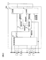
以下、図を参照して本発明による電池監視システムを採用した車両用回転電機の駆動システムについて説明する。図1は、本発明による電池監視システムを採用した車両用回転電機の駆動システムを示すブロック図である。図1に示す駆動システムは、電池モジュール9、電池モジュール9を監視する電池監視システム100、電池モジュール9からの直流電力を3相交流電力に変換するインバータ装置220、および車両駆動用のモータ230を備えている。モータ230は、インバータ装置220からの3相交流電力により駆動される。インバータ装置220と電池監視システム100とはCAN通信で結ばれており、インバータ装置220は電池監視システム100に対して上位コントローラとして機能する。また、インバータ装置220は、さらに上位のコントローラ(不図示)からの指令情報に基づいて動作する。
Hereinafter, a drive system for a rotating electrical machine for a vehicle that employs a battery monitoring system according to the present invention will be described with reference to the drawings. FIG. 1 is a block diagram showing a drive system for a rotating electrical machine for a vehicle that employs a battery monitoring system according to the present invention. The drive system shown in FIG. 1 includes a
インバータ装置220は、パワーモジュール226と、パワーモジュール226を駆動するためのドライバ回路224と、ドライバ回路224を制御するためのMCU222とを有している。パワーモジュール226は、電池モジュール9から供給される直流電力を、モータ230を駆動するための3相交流電力に変換する。なお、図示していないが、パワーモジュール226が電池モジュール9に接続される強電ラインHV+,HV−間には、約700μF〜約2000μF程度の大容量の平滑キャパシタが設けられている。この平滑キャパシタは、電池監視システム100に設けられた集積回路に加わる電圧ノイズを低減する働きをする。
The
インバータ装置220の動作開始状態では平滑キャパシタの電荷は略ゼロであるため、後述する電池ディスコネクトユニットBDUのリレーRLを閉じると、大きな初期電流が電池モジュール9から平滑キャパシタへ流れ込む。この大電流のために、リレーRLが融着して破損するおそれがある。この問題を解決するために、MCU222は、さらに上位のコントローラからの命令に従い、モータ230の駆動開始時に、まずプリチャージリレーRLPを開状態から閉状態にして平滑キャパシタを充電する。このとき、抵抗RPを介して最大電流を制限しながら平滑キャパシタの充電を行う。その後にリレーRLを開状態から閉状態として、電池モジュール9からインバータ装置220への電力の供給を開始する。このような動作を行うことで、リレー回路を保護すると共に、電池モジュール9やインバータ装置220を流れる最大電流を所定値以下に低減でき、高い安全性を維持できる。
Since the charge of the smoothing capacitor is substantially zero in the operation start state of the
なお、インバータ装置220は、モータ230の回転子に対してパワーモジュール226により発生する交流電力の位相を制御して、車両制動時にはモータ230を発電機として動作させる。すなわち回生制動制御を行い、発電機運転により発電された電力を電池モジュール9に回生して電池モジュール9を充電する。電池モジュール9の充電状態が基準状態より低下した場合にも、インバータ装置220はモータ230を発電機として運転する。モータ230で発電された3相交流電力は、パワーモジュール226により直流電力に変換されて電池モジュール9に供給される。その結果、電池モジュール9は充電される。
回生制動制御により電池モジュール9を充電する場合には、MCU222は、モータ230の回転子の回転に対して遅れ方向の回転磁界を発生するようにドライバ回路224を制御する。この制御に応じて、ドライバ回路224はパワーモジュール226のスイッチング動作を制御する。これにより、モータ230からの交流電力がパワーモジュール226に供給され、パワーモジュール226により直流電力に変換されて電池モジュール9へ供給される。その結果、モータ230は発電機として作用することとなる。
When the
一方、モータ230を力行運転する場合には、MCU222は、上位コントローラの命令に従い、モータ230の回転子の回転に対して進み方向の回転磁界を発生するようにドライバ回路224を制御する。この制御に応じて、ドライバ回路224はパワーモジュール226のスイッチング動作を制御する。これにより、電池モジュール9からの直流電力がパワーモジュール226に供給され、パワーモジュール226により交流電力に変換されてモータ230へ供給される。
On the other hand, when powering the
インバータ装置220のパワーモジュール226は、導通および遮断動作を高速で行い直流電力と交流電力間の電力変換を行う。このとき、大電流を高速で遮断するので、直流回路の有するインダクタンスにより大きな電圧変動が発生する。この電圧変動を抑制するため、インバータ装置220には上述した大容量の平滑キャパシタが設けられている。
The
電池モジュール9は、複数の電池モジュールブロックによって構成されている。図1に示す例では、直列接続された2つの電池モジュールブロック9A、9Bで電池モジュール9が構成されている。各電池モジュールブロック9A、9Bは、複数の電池セルを直列接続したセルグループをさらに複数直列に接続されたものを備えている。電池モジュールブロック9Aと電池モジュールブロック9Bとは、スイッチとヒューズとが直列接続された保守・点検用のサービスディスコネクトSDを介して直列接続される。このサービスディスコネクトSDが開くことで電池モジュールブロック9Aと9Bの直接回路が遮断されるため、仮に電池モジュールブロック9A、9Bのどこかで車両との間に1箇所接続回路ができたとしても電流が流れることはない。このような構成により高い安全性を維持できる。また、点検時にサービスディスコネクトSDを開くことで、作業者がHV+とHV−の間を触っても、高電圧が人体に印加されないので安全である。
The
電池モジュール9とインバータ装置220との間の強電ラインHV+には、リレーRL,抵抗RPおよびプリチャージリレーRLPを備えた電池ディスコネクトユニットBDUが設けられている。抵抗RPとプリチャージリレーRLPとの直列回路は、リレーRLと並列に接続されている。
A high voltage line HV + between the
電池監視システム100は、電池モジュール9の状態を監視するための監視動作として、主に電池モジュール9の各セルに対する電圧の測定、総電圧の測定、電流の測定、セル温度およびセルの容量調整等を行う。そのために、電池監視システム100は、複数の電池監視装置BM1〜BM4と、各電池監視装置BM1〜BM4を制御するためのマイコン30とを有している。各電池モジュールブロック9A、9B内に設けられた複数の電池セルは、複数のセルグループに分けられている。電池監視システム100には、この各セルグループ毎に、各セルグループに含まれる電池セルを監視する電池監視装置BM1〜BM4が1つずつ設けられている。マイコン30は、電池監視装置BM1〜BM4に対して上位コントローラとして機能する。
The
以下では説明を簡単にするため、各セルグループは直列接続された4個の電池セルで構成されているとする。また各電池モジュールブロック9A、9Bは、2つのセルグループでそれぞれ構成されているとする。しかしながら、各セルグループに含まれる電池セルは4個に限定するものでなく、5個あるいはこれ以上であってもよく、また3個以下であってもよい。1つの電池セルにより1つのセルグループを構成してもよい。すなわち、1つまたは直列接続された複数の電池セルによって構成されるセルグループの各々は、電池監視装置BM1〜BM4が監視対象とする電池にそれぞれ相当するものである。また、異なる電池セル数のセルグループ、例えば4個の電池セルによるセルグループと6個の電池セルによるセルグループとが組み合わされていてもよい。各セルグループに対応して設けられる電池監視装置BM1〜BM4は、これらのセルグループに含まれる電池セルの数が任意の数、例えば4個であっても、また5個以上であっても使用できるように設計したものを使用することができる。
Hereinafter, in order to simplify the description, it is assumed that each cell group includes four battery cells connected in series. Each
また、電気自動車やハイブリッド自動車で必要とされる電圧および電流を得るために、上記のように各電池モジュールブロックではセルグループを複数個直列または直並列に接続してもよい。さらに、複数の電池モジュールブロックを直列または直並列に接続してもよい。 Further, in order to obtain a voltage and current required for an electric vehicle or a hybrid vehicle, a plurality of cell groups may be connected in series or series-parallel in each battery module block as described above. Further, a plurality of battery module blocks may be connected in series or in series and parallel.
電池監視装置BM1〜BM4は、各々がマイコン30との間で無線通信を行うためのアンテナを備えている。マイコン30は、アンテナを備えた無線通信部RFと接続されている。この無線通信部RFを介して、マイコン30は各電池監視装置BM1〜BM4と無線通信を行い、各電池監視装置BM1〜BM4に対してそれぞれ対応するセルグループの状態を監視するように指示する。また、各電池監視装置BM1〜BM4から送信される各セルグループの状態の監視結果を受信する。
Each of the battery monitoring devices BM1 to BM4 includes an antenna for performing wireless communication with the
マイコン30から無線通信部RFを介して電池監視装置BM1〜BM4へ送信される無線信号には、電池監視装置BM1〜BM4の中でどの電池監視装置に監視動作を実行させるかを指定するためのID情報と、ID情報で指定された電池監視装置が対応するセルグループに対して実行する監視動作の内容を指定するためのコマンド情報とを含む。無線通信部RFは、マイコン30から出力されるこれらの情報を所定の変調方式で変調することにより無線信号を生成し、電池監視装置BM1〜BM4へ送信する。
A wireless signal transmitted from the
電池監視装置BM1〜BM4には、互いに異なる固有のIDが製造時に予め設定されている。マイコン30から無線信号が送信されると、各電池監視装置BM1〜BM4は、その無線信号に含まれるID情報を設定されているIDと比較することで、その無線信号が自身に対して送信されたものであるか否かを判断する。
In the battery monitoring devices BM1 to BM4, different unique IDs are set in advance at the time of manufacture. When a wireless signal is transmitted from the
なお、電池モジュール9と電池監視装置BM1〜BM4とは、図1の駆動システムに搭載されて車両に組み込まれる前には、互いに接続された状態で組電池として所定の保管場所に保管される。この保管時の電池状態を管理するために、後述する電池状態管理装置と電池監視装置BM1〜BM4との間で無線通信が行われる。このときの具体的な動作については、後で説明する。
The
電池ディスコネクトユニットBDU内にはホール素子等の電流センサSiが設置されている。電流センサSiの出力はマイコン30に入力される。電池モジュール9の総電圧および温度に関する信号もマイコン30に入力され、それぞれマイコン30のAD変換器(ADC)によって測定される。温度センサは電池モジュールブロック9A,9B内の複数箇所に設けられている。
A current sensor Si such as a hall element is installed in the battery disconnect unit BDU. The output of the current sensor Si is input to the
図2は、本発明による電池監視装置BM1の構成を示すブロック図である。なお、説明は省略するが、他の電池監視装置BM2〜BM4に関しても同様の構成となっている。 FIG. 2 is a block diagram showing the configuration of the battery monitoring device BM1 according to the present invention. Although not described, the other battery monitoring devices BM2 to BM4 have the same configuration.
図2に示すように、電池監視装置BM1は、受信部31、認証回路33、電源回路34、電池監視回路35および送信部36を有する。
As illustrated in FIG. 2, the battery monitoring device BM1 includes a
受信部31は、マイコン30や前述の電池状態管理装置から送信される無線信号を受信すると、その無線信号が電池監視装置BM1に対して送信されたものである否かを確認する。この確認は、無線信号に含まれる前述のID情報が示すIDと、電池監視装置BM1に対して割り当てられたIDとを比較し、これらが一致するか否かを判別することで行うことができる。その結果、両IDが一致していれば、受信した無線信号が電池監視装置BM1に対して送信されたものであると判断し、その無線信号を復調して得られた復調信号に含まれる前述のコマンド情報に基づくコマンドを電池監視回路35へ出力する。
When receiving the wireless signal transmitted from the
認証回路33は、マイコン30や電池状態管理装置との間で無線通信を開始する前に、受信部31からの認証要求に応じて、その通信先が正当な通信先であるか否かを判定するための認証を行う。その結果、正当な通信先であると判定された場合にのみ、電池監視装置BM1と当該通信先との間で無線通信を開始することができる。認証回路33による認証結果は送信部36へ出力され、送信部36から当該通信先へと送信される。
The
電源回路34は、認証回路33、電池監視回路35および送信部36への電源供給を行う。電源回路34からの電源供給は、電池監視装置BM1が接続されている電池セルBC1〜BC4の電力を用いて行われる。
The power supply circuit 34 supplies power to the
電池監視回路35は、電池監視装置BM1に対応するセルグループを構成する電池セルBC1〜BC4と接続されており、受信部31からのコマンドに応じて、電池セルBC1〜BC4の状態を監視するための監視動作を行う。このとき電池監視回路35は、前述のような様々な監視動作のうち、受信部31から出力されるコマンドによって指定された内容の監視動作を電池セルBC1〜BC4に対して行う。すなわち、マイコン30からの無線信号に含まれるコマンド情報に基づいて、受信部31から電池監視回路35へコマンドが出力されることにより、電池監視回路35が行う監視動作の内容が決定される。電池監視回路35は、電池セルBC1〜BC4に対して監視動作を行ったら、その結果をセル状態監視結果として送信部36へ出力する。
The
送信部36は、電池監視回路35から出力されたセル状態監視結果を所定の変調方式で変調することにより無線信号を生成し、図1のマイコン30へ送信する。マイコン30では、送信部36から送信された無線信号を無線通信部RFを介して受信することにより、電池セルBC1〜BC4に対する監視結果を電池監視装置BM1から取得することができる。
The transmitting
図3は、電池監視装置BM1における電池監視回路35の内部ブロックを示す図である。なお、説明は省略するが、他の電池監視装置BM2〜BM4の電池監視回路35に関してもこれと同様である。
FIG. 3 is a diagram showing an internal block of the
図1の電池モジュール9は、電池監視装置BM1〜BM4に対応して4つのセルグループに分かれている。電池監視装置BM1に対応するセルグループGB1には、図2に示した4つの電池セルBC1〜BC4が含まれている。
The
電池監視回路35の各入力側端子は、セルグループGB1を構成する電池セルBC1〜BC4にそれぞれ接続されている。電池セルBC1の正極端子は、入力端子V1を介して入力回路116に接続されている。この入力回路116はマルチプレクサを含む。電池セルBC1の負極端子であって電池セルBC2の正極端子は入力端子V2を介して、電池セルBC2の負極端子であって電池セルBC3の正極端子は入力端子V3を介して、電池セルBC3の負極端子であって電池セルBC4の正極端子は入力端子V4を介して、それぞれ入力回路116に接続されている。電池セルBC4の負極端子は、電池監視回路35の端子GNDに接続されている。
Each input side terminal of the
電圧検出回路122は、各電池セルBC1〜BC4のそれぞれの端子間電圧をデジタル値に変換する回路を有している。デジタル値に変換された各端子間電圧はIC制御回路123に送られ、内部の記憶回路125に保持される。これらの電圧は自己診断などに利用されたり、図1に示すマイコン30に送信されたりする。
The
IC制御回路123は、演算機能を有すると共に、記憶回路125と、各種電圧の検知や状態診断を周期的に行うタイミング制御回路252を有している。記憶回路125は、例えばレジスタ回路で構成されている。電圧検出回路122で検出した各電池セルBC1〜BC4の各端子間電圧は、IC制御回路123の記憶回路125において、各電池セルBC1〜BC4に対応づけて記憶される。また、その他の様々な検出値についても、記憶回路125において予め定められたアドレスに読出し可能に保持することができる。
The
IC制御回路123には、通信回路127が接続されている。IC制御回路123は、この通信回路127を介して、図2の受信部31により出力されたマイコン30からのコマンドが入力されると共に、セル状態監視結果を送信部36へ出力して送信部36によりマイコン30へ送信する。受信部31からコマンドが送られると、IC制御回路123はそのコマンドの内容を解読し、コマンド内容に応じた処理を行う。マイコン30からのコマンドは、たとえば、各電池セルBC1〜BC4の端子間電圧の計測値を要求するコマンド、各電池セルBC1〜BC4の充電状態を調整するための放電動作を要求するコマンド、電池監視装置BM1の動作を開始するコマンド(Wake UP)、動作を停止するコマンド(スリープ)、アドレス設定を要求するコマンド、等を含む。
A
電池セルBC1の正極端子は、抵抗R1を介して電池監視回路35の端子B1に接続されている。この端子B1と端子V2との間にはバランシングスイッチ129Aが設けられている。バランシングスイッチ129Aには、このスイッチの動作状態を検出するための動作状態検出回路128Aが並列接続されている。このバランシングスイッチ129Aは放電制御回路132によって開閉が制御される。同様に、電池セルBC2の正極端子は抵抗R2を介して端子B2に接続され、この端子B2と端子V3との間にはバランシングスイッチ129Bが設けられている。バランシングスイッチ129Bには、このスイッチの動作状態を検出するための動作状態検出回路128Bが並列接続されている。このバランシングスイッチ129Aは放電制御回路132によって開閉が制御される。
The positive terminal of the battery cell BC1 is connected to the terminal B1 of the
電池セルBC3の正極端子は抵抗R3を介して端子B3に接続され、この端子B3はと端子V4との間にはバランシングスイッチ129Cが設けられている。バランシングスイッチ129Cには、このスイッチの動作状態を検出するための動作状態検出回路128Cが並列接続されている。このバランシングスイッチ129Cは放電制御回路132によって開閉制御される。電池セルBC4の正極端子は抵抗R4を介して端子B4に接続され、この端子B4と端子GNDとの間にはバランシングスイッチ129Dが設けられている。バランシングスイッチ129Dには、このスイッチの動作状態を検出するための動作状態検出回路128Dが並列接続されている。このバランシングスイッチ129Cは放電制御回路132によって開閉が制御される。
The positive terminal of the battery cell BC3 is connected to the terminal B3 via the resistor R3, and a balancing
動作状態検出回路128A〜128Dは、それぞれ各バランシングスイッチ129A〜129Dの両端電圧を所定周期で繰り返し検出し、各バランシングスイッチ129A〜129Dが正常であるかどうかを検出する。バランシングスイッチ129A〜129Dは電池セルBC1〜電池セルBC4の充電状態を調整するスイッチである。これらスイッチが異常の場合、電池セルの充電状態を制御できなくなり、一部の電池セルが過充電あるいは過放電になる恐れがある。たとえば、あるバランシングスイッチが導通している状態であるにもかかわらず、その端子間電圧が対応する電池セルの端子電圧を示す場合に、当該バランシングスイッチが異常であると検出する。この場合は、当該バランシングスイッチが制御信号に基づく導通状態になっていないこととなる。また、あるバランシングスイッチが開放状態であるにもかかわらず、その端子間電圧が対応する電池セルの端子電圧に比べて低い値である場合にも、当該バランシングスイッチが異常であると検出する。この場合は、当該バランシングスイッチは制御信号に関係なく導通していることとなる。このようにしてバランシングスイッチ129A〜129Dの異常検出を行う動作状態検出回路128A〜128Dには、たとえば差動アンプ等で構成される電圧検出回路が用いられる。
The operation
バランシングスイッチ129A〜129Dは、たとえばMOS型FETで構成され、それぞれ対応する電池セルBC1〜BC4に蓄積された電力を放電させる作用をする。多数の電池セルが直列接続されている電池モジュール9に対してインバータなどの電気負荷が接続されると、その電気負荷に対する電流の供給は、直列接続された多数の電池セルの全体で行われる。このとき、各電池セルが互いに異なる充電状態(SOC)にあると、電池モジュール9において最も放電されている電池セルの状態により電流が制限されてしまうこととなる。一方、電池モジュール9が充電される状態では、電池モジュール9への電流の供給は、直列接続された多数の電池セルの全体に対して行われる。このとき、各電池セルが互いに異なる充電状態(SOC)にあると、電池モジュール9において最も充電されている電池セルの状態により電流が制限されてしまうこととなる。
Balancing switches 129A to 129D are made of, for example, MOS FETs, and act to discharge the electric power stored in corresponding battery cells BC1 to BC4, respectively. When an electric load such as an inverter is connected to the
そこで、上記のように各電池セルの充電状態の違いによって電流が制限されてしまうのを解消するため、以下のようなバランシングを必要に応じて行う。具体的には、電池モジュール9において直列接続されている多数の電池セルのうち、所定の充電状態、たとえば各電池セルの充電状態の平均値を越えた充電状態にある電池セルに対して、当該電池セルに接続されているバランシングスイッチを導通状態とする。これにより、導通状態としたバランシングスイッチに直列接続されている抵抗を介して、当該電池セルから放電電流を流す。その結果、各電池セルの充電状態が互いに近づく方向に制御されることとなる。また他の方法として、電池モジュール9において最も放電状態にある電池セルを基準セルとし、この基準セルとの充電状態の差に基づき放電時間を決める方法もある。その他にも、各電池セルの充電状態を調整するために様々なバランシング方法を用いることができる。なお、各電池セルの充電状態は、各電池セルの端子電圧を基に演算で求めることができる。各電池セルの充電状態と端子電圧には相関関係が有るので、各電池セルの端子電圧を互いに近づけるようにバランシングスイッチ129A〜129Dを制御することで、各電池セルの充電状態を互いに近づけることができる。
Therefore, the following balancing is performed as necessary in order to eliminate the current limitation due to the difference in the charging state of each battery cell as described above. Specifically, among a large number of battery cells connected in series in the
バランシングスイッチ129A〜129Dの端子間電圧、すなわちバランシングスイッチ129A〜129Dを構成する各FETのソースとドレイン間の電圧は、動作状態検出回路128A〜128Dによって検出され、電位変換回路130に出力される。ここで、各FETのソースとドレイン間の電位は、基準電位に対してそれぞれ異なっているため、このままでは比較判断が難しい。そこで、電位変換回路130でこれらの電位をそろえ、次に異常判定回路131で異常判定する。また、電位変換回路130は、バランシングスイッチ129A〜129Dの中で診断すべきバランシングスイッチをIC制御回路123からの制御信号に基づき選択する機能も有している。選択されたバランシングスイッチの端子間電圧が電位変換回路130から異常判定回路131に送られると、異常判定回路131はIC制御回路123から制御信号に基づき、その端子間電圧を所定の判定電圧と比較する。これにより、異常判定回路131はバランシングスイッチ129A〜129Dが異常か否かを判定することができる。
The voltage between the terminals of the balancing switches 129A to 129D, that is, the voltage between the source and drain of each FET constituting the balancing switches 129A to 129D is detected by the operation
放電制御回路132には、IC制御回路123から放電させるべき電池セルに対応したバランシングスイッチを導通させるための指令信号が送られる。この指令信号に基づき、放電制御回路132は、上述したようにMOS型FETから構成されるバランシングスイッチ129A〜129Dの導通を行うゲート電圧に相当する信号を出力する。
The
IC制御回路123は、図1のマイコン30からのコマンドにより、電池セルに対応した放電時間の指令を受け、上記のような放電の動作を実行する。またIC制御回路123は、バランシングスイッチ129A〜129Dの異常を検出すると、その検出結果を図2に示したセル状態監視結果として送信部36へ出力することにより、送信部36からマイコン30へ無線送信する。
The
次に、保管時における電池状態の管理について説明する。図4は、本実施形態による電池状態管理システムの概略構成を示す図である。この電池状態管理システムは、図1の駆動システムに搭載されて車両に組み込まれる前の組電池AB1と、電池状態管理装置40によって構成される。 Next, battery state management during storage will be described. FIG. 4 is a diagram showing a schematic configuration of the battery state management system according to the present embodiment. This battery state management system includes an assembled battery AB1 that is mounted on the drive system of FIG.
組電池AB1は、電池モジュール9と電池監視装置BM1〜BM4とが互いに接続されることによって構成される。この組電池AB1は、たとえば工場、船舶等の輸送機関、流通拠点などにおいて、倉庫などの所定の保管場所に保管される。各電池監視装置BM1〜BM4には、予め固有のID_A1〜ID_D1がそれぞれ設定されている。
The assembled battery AB1 is configured by connecting the
なお、上記の保管場所には、組電池AB1以外にも多数の組電池が一緒に保管されるが、図4では組電池AB1を代表例として示している。他の組電池も、組電池AB1と同様の構成を有している。 In addition to the assembled battery AB1, a large number of assembled batteries are stored together in the storage location, but FIG. 4 shows the assembled battery AB1 as a representative example. Other assembled batteries also have the same configuration as the assembled battery AB1.
電池状態管理装置40は、上記保管場所に組電池AB1として保管されている電池モジュール9の状態を管理するための装置であり、管理対象とする組電池の各電池監視装置との間で無線通信を行う。電池状態管理装置40には、予め固有のID_CBが設定されている。電池状態管理装置40が管理対象とする組電池は、電池状態管理装置40に記憶されている固有IDによって定められる。図4に示した例では、N個の組電池ABx(x=1〜N)について、それぞれに含まれる各電池監視装置の固有ID_Ax〜ID_Dxが電池状態管理装置40に記憶されている。なお、これらの固有IDを電池状態管理装置40に記憶させる方法については、後で説明する。
The battery
電池状態管理装置40にはまた、認証用の鍵情報を生成するためのテーブル情報である鍵生成テーブルが記憶されている。電池状態管理装置40は、管理対象である組電池AB1の各電池監視装置BM1〜BM4との間で無線通信を開始する際には、鍵生成テーブルを参照して鍵情報を生成し、その鍵情報を各電池監視装置BM1〜BM4へ送信する。すると、各電池監視装置BM1〜BM4では、電池状態管理装置40から受信した鍵情報に基づいて、認証回路33(図2参照)により認証が行われ、電池状態管理装置40が正当な通信先であるか否かが判断される。その結果、正当な通信先であると判断されると、電池状態管理装置40と各電池監視装置BM1〜BM4との間で無線通信が開始される。
The battery
以上説明したような電池状態管理装置40は、たとえば、パソコンと無線機器をUSB等により接続したもので構成される。すなわち、パソコン上で所定のプログラムを実行して無線機器を制御し、無線機器に対して管理対象とする組電池の各電池監視装置との間で無線通信を行わせることにより、電池状態管理装置40が実現される。
The battery
以上説明した電池状態管理システムによる電池状態管理方法を図5を用いて説明する。組電池AB1は、たとえば工場からの出荷検査時などに、出荷検査装置50によって電池監視装置BM1〜BM4の固有ID_A1〜ID_D1が読み出され、これらの固有IDに関する情報が出荷検査装置50に吸い上げられる。出荷検査装置50に吸い上げられた固有ID_A1〜ID_D1の情報は、検査結果ファイルサーバ60に登録される。
The battery state management method by the battery state management system described above will be described with reference to FIG. In the assembled battery AB1, for example, at the time of shipping inspection from a factory, the unique ID_A1 to ID_D1 of the battery monitoring devices BM1 to BM4 are read by the
検査結果ファイルサーバ60に登録された固有ID_A1〜ID_D1の情報は、組電池AB1を管理対象として電池モジュール9の状態を管理するときに、事前に電池状態管理装置40によって読み出され、電池状態管理装置40において記憶される。同様にして、倉庫内に保管されている梱包状態の組電池AB1〜AB6を管理対象として電池状態の管理を行うときには、これらに含まれる電池監視装置の固有IDが検査結果ファイルサーバ60からそれぞれ事前に読み出され、電池状態管理装置40に記憶される。このようにして、管理対象とする組電池AB1〜AB6に含まれる各電池監視装置の固有IDを電池状態管理装置40に記憶させておくことで、電池状態管理装置40は各組電池AB1〜AB6との間で無線通信を行い、これらの状態管理を行うことができる。
The information of the unique ID_A1 to ID_D1 registered in the inspection
続いて、本実施形態の電池状態管理システムにおける電池状態管理の処理手順について説明する。図6は、電池状態管理装置40の処理手順を示すフローチャートであり、図7は、組電池AB1を管理対象としたときの電池監視装置BM1の処理手順を示すフローチャートである。なお、以下では組電池AB1を管理対象としたときの処理手順を例として説明するが、他の組電池を管理対象としたときも同様である。また、組電池AB1の電池監視装置BM1〜BM4のうち、電池監視装置BM1の処理手順を例として説明するが、他の電池監視装置BM2〜BM4でも同様である。
Next, a battery state management process procedure in the battery state management system of the present embodiment will be described. FIG. 6 is a flowchart showing a processing procedure of the battery
図6のステップS10において、電池状態管理装置40は、検査結果ファイルサーバ60に登録されている固有IDの一覧を取得する。こうして取得された固有IDの一覧から、管理対象とする組電池AB1に含まれる電池監視装置BM1〜BM4に対する固有ID_A1〜ID_D1を選択すると、その情報が検査結果ファイルサーバ60から読み出され、電池状態管理装置40において記憶される。
In step S <b> 10 of FIG. 6, the battery
ステップS20において、電池状態管理装置40は、管理対象とする組電池AB1の各電池監視装置BM1〜BM4との間で所定の認証処理を行う。ここで認証処理が行われることにより、電池状態管理装置40が正当な通信先であるか否かの判定が各電池監視装置BM1〜BM4において行われ、その判定の結果が認証結果として各電池監視装置BM1〜BM4から電池状態管理装置40へ送信される。なお、認証処理の具体的な手順については、後で図8を用いて説明する。
In step S20, the battery
ステップS30において、電池状態管理装置40は、各電池監視装置BM1〜BM4から送信された認証結果に基づいて、認証OKであるか否かを判定する。認証OKである場合、すなわち電池監視装置BM1〜BM4の全てにおいて電池状態管理装置40が正当な通信先であるとそれぞれ判定された場合は、ステップS40へ進む。一方、認証OKでない場合、すなわち電池監視装置BM1〜BM4のいずれか少なくとも1つにおいて電池状態管理装置40が正当な通信先ではないと判定された場合は、図6のフローチャートに示す処理を終了する。
In step S30, the battery
ステップS40において、電池状態管理装置40は、各電池監視装置BM1〜BM4から、それぞれが接続されているセルグループの各電池セルにおけるセル電圧および温度の測定結果を取得する。このとき電池状態管理装置40は、後述する図7のステップS250の処理によって各電池監視装置BM1〜BM4からセル状態監視結果として送信されるセル電圧および温度の測定結果を受信する。これにより、電池監視装置BM1〜BM4に接続されている各セルグループの各電池セルにおけるセル電圧および温度の測定結果を取得する。
In step S40, the battery
ステップS50において、電池状態管理装置40は、ステップS40で取得したセル電圧および温度の測定結果に基づいて、電池監視装置BM1〜BM4が接続されているセルグループの各電池セルの状態が異常であるか否かを判定する。この判定は、たとえば、測定されたセル電圧や温度が予め設定された所定の範囲にあるか否かにより行うことができる。すなわち、セル電圧や温度が所定の範囲内にあれば正常であると判定し、範囲外にあれば異常であると判定する。なお、これ以外の判定方法を用いて電池セルの状態が異常であるか否かを判定してもよい。電池監視装置BM1〜BM4の全ての電池セルが異常なしの場合はステップS60へ進み、いずれか少なくとも1つの電池セルに異常がある場合はステップS150へ進む。
In step S50, the battery
ステップS60において、電池状態管理装置40は、ステップS40で取得したセル電圧の測定結果に基づいて、各電池監視装置BM1〜BM4に対してバランシングの必要があるか否かを判定する。この判定は、たとえば、測定されたセルグループの各セル電圧に基づいて各電池セルの充電状態を推測し、その中に前述のようなバランシングの条件を満たすものがあるか否かにより行うことができる。電池監視装置BM1〜BM4の全てについてバランシングの必要がないと判定した場合は図6のフローチャートに示す処理を終了し、いずれか少なくとも1つの電池監視装置についてバランシングの必要があると判定した場合はステップS70へ進む。
In step S60, the battery
ステップS70において、電池状態管理装置40は、ステップS60でバランシングの必要があると判定した電池監視装置に対して、当該電池監視装置が接続されているセルグループの電池セルの中でバランシング対象とする電池セル(調整セル)を決定すると共に、その調整セルの目標電圧を決定する。これらの決定は、ステップS40で取得したセル電圧の測定結果のうち、当該電池監視装置に対応するセルグループの各セル電圧の測定結果に基づいて行うことができる。
In step S70, the battery
ステップS80において、電池状態管理装置40は、ステップS60でバランシングの必要があると判定した電池監視装置に対して、ステップS70で決定した調整セルおよび目標電圧に応じた放電要求コマンドを送信する。これにより、当該電池監視装置に対して、対応するセルグループにおける調整セルのセル電圧が目標電圧に達するまで調整セルを放電させるように指示を行う。
In step S80, the battery
ステップS90において、電池状態管理装置40は、内部に保有するタイマーを初期化し、タイマーによる時間測定を開始する。
In step S90, the battery
ステップS100において、電池状態管理装置40は、ステップS80で放電要求コマンドを送信した電池監視装置から、対応するセルグループの各電池セルにおけるセル電圧および温度の測定結果を取得する。このとき電池状態管理装置40は、後述する図7のステップS290の処理によって当該電池監視装置からセル状態監視結果として送信されるセル電圧および温度の測定結果を受信する。これにより、当該電池監視装置に接続されているセルグループの各電池セルにおけるセル電圧および温度の測定結果を取得する。
In step S100, the battery
ステップS110において、電池状態管理装置40は、ステップS100で取得したセル電圧および温度の測定結果に基づいて、当該電池監視装置が接続されているセルグループの各電池セルの状態が異常であるか否かを判定する。この判定は、前述のステップS50と同様の判定方法により行うことができる。当該電池監視装置の全ての電池セルが異常なしの場合はステップS120へ進み、いずれか少なくとも1つの電池セルに異常がある場合はステップS140へ進む。
In step S110, the battery
ステップS120において、電池状態管理装置40は、ステップS80で放電要求コマンドを送信した電池監視装置においてバランシングが完了したか否かを判定する。この判定は、後述する図7のステップS340の処理によって当該電池監視装置からバランシング完了報告が送信されたか否かにより行うことができる。すなわち、当該電池監視装置からバランシング完了報告が送信された場合は、バランシング完了と判定して図6のフローチャートに示す処理を終了し、バランシング完了報告が送信されない場合は、ステップS130へ進む。
In step S120, the battery
ステップS130において、電池状態管理装置40は、タイマーによる測定時間が予め設定された所定のタイムアウト時間を経過したか否かを判定する。タイマーによる測定時間がタイムアウト時間未満であればステップS100へ戻り、前述のステップS100〜S130の処理を継続する。一方、タイムアウト時間以上であればステップS70へ戻る。この場合、直前に実行したステップS100において取得したセル電圧および温度の測定結果に基づいて、調整セルおよび目標電圧を再度決定し、その結果に応じた放電要求コマンドを当該電池監視装置に対して再送信する。
In step S <b> 130, the battery
ステップS140において、電池状態管理装置40は、ステップS80で放電要求コマンドを送信した後にステップS110で電池セルの状態が異常であると判定した電池監視装置に対して、バランシングを停止させるための放電停止コマンドを送信する。これにより、バランシング中に電池セルの状態に異常があると判定された電池監視装置に対して、調整セルの放電を停止させるような指示を行う。
In step S140, the battery
ステップS150において、電池状態管理装置40は、ステップS50またはS1100で電池セルの状態が異常であると判定した電池監視装置について、その異常を電池状態管理装置40の操作者に知らせるための警告を行う。この警告は、たとえば所定の警告メッセージを電池状態管理装置40において画面表示したり音声出力したりすることにより行われる。
In step S150, the battery
ステップS160において、電池状態管理装置40は、ステップS150で行った警告に応じた異常結果を記録する。
In step S160, the battery
ステップS160を実行したら、電池状態管理装置40は図6のフローチャートに示す処理を終了する。
If step S160 is performed, the battery
図7のステップS210において、電池監視装置BM1は、受信部31、認証回路33および送信部36を用いて、電池状態管理装置40との間で所定の認証処理を行う。この認証処理は、前述の図6のステップS20で電池状態管理装置40によって行われるものに対応しており、その具体的な手順については後で図8を用いて説明する。
In step S210 of FIG. 7, the battery monitoring device BM1 performs predetermined authentication processing with the battery
ステップS220において、電池監視装置BM1は、受信部31、認証回路33および送信部36を用いて、ステップS210で行った認証処理の結果を電池状態管理装置40へ送信する。
In step S220, the battery monitoring device BM1 transmits the result of the authentication process performed in step S210 to the battery
ステップS230において、電池監視装置BM1は、認証回路33により、ステップS210で行った認証処理の結果がOKであるか否かを判定する。認証OKである場合、すなわち認証処理において電池状態管理装置40が正当な通信先であると判定した場合は、ステップS240へ進む。一方、認証OKでない場合、すなわち認証処理において電池状態管理装置40が正当な通信先ではないと判定した場合は、図7のフローチャートに示す処理を終了する。
In step S230, the battery monitoring device BM1 determines whether or not the result of the authentication process performed in step S210 is OK by the
ステップS240において、電池監視装置BM1は、電池監視回路35を用いて、接続されているセルグループの各電池セルにおけるセル電圧および温度を測定する。
In step S240, the battery monitoring device BM1 uses the
ステップS250において、電池監視装置BM1は、ステップS240で測定したセル電圧および温度をセル状態監視結果として電池監視回路35から送信部36へ出力し、これらの監視結果を送信部36により電池状態管理装置40へ送信する。これにより、電池監視装置BM1が接続されているセルグループの各電池セルにおけるセル電圧および温度の測定結果が、当該各電池セルに対するセル状態監視結果として電池監視装置BM1から電池状態管理装置40に送信される。
In step S250, the battery monitoring device BM1 outputs the cell voltage and temperature measured in step S240 as cell state monitoring results from the
ステップS260において、電池監視装置BM1は、受信部31により、図6のステップS80で電池状態管理装置40から送信された放電要求コマンドを受信したか否かを判定する。電池監視装置BM1に対する放電要求コマンドを電池状態管理装置40から受信した場合はステップS270へ進み、受信していない場合は図7のフローチャートに示す処理を終了する。
In step S260, the battery monitoring device BM1 determines whether the receiving
ステップS270において、電池監視装置BM1は、電池状態管理装置40から受信した放電要求コマンドに応じて、図3のバランシングスイッチ129A〜129Dの開閉を制御する。ここでは、受信部31により放電要求コマンドを受信すると、その放電要求コマンドを受信部31から電池監視回路35へ出力する。電池監視回路35は、放電制御回路132により、バランシングスイッチ129A〜129Dのうち放電要求コマンドで指定された調整セルに対応するバランシングスイッチを閉じるように制御する。
In step S270, the battery monitoring device BM1 controls the opening / closing of the balancing switches 129A to 129D of FIG. 3 according to the discharge request command received from the battery
ステップS280において、電池監視装置BM1は、ステップS240と同様に、電池監視回路35を用いて、接続されているセルグループの各電池セルにおけるセル電圧および温度を測定する。
In step S280, the battery monitoring device BM1 measures the cell voltage and temperature in each battery cell of the connected cell group using the
ステップS290において、電池監視装置BM1は、ステップS280で測定したセル電圧および温度をセル状態監視結果として電池監視回路35から送信部36へ出力し、これらの監視結果を送信部36により電池状態管理装置40へ送信する。これにより、ステップS250と同様に、電池監視装置BM1が接続されているセルグループの各電池セルにおけるセル電圧および温度の測定結果が、当該各電池セルに対するセル状態監視結果として電池監視装置BM1から電池状態管理装置40に送信される。
In step S290, the battery monitoring device BM1 outputs the cell voltage and temperature measured in step S280 as cell state monitoring results from the
ステップS300において、電池監視装置BM1は、受信部31により、図6のステップS140で電池状態管理装置40から送信された放電停止コマンドを受信したか否かを判定する。電池監視装置BM1に対する放電停止コマンドを電池状態管理装置40から受信した場合はステップS330へ進み、受信していない場合はステップS310へ進む。
In step S300, the battery monitoring device BM1 determines whether the receiving
ステップS310において、電池監視装置BM1は、電池監視回路35により、電池状態管理装置40から受信した放電要求コマンドで指定された調整セルの目標電圧と、ステップS280で測定したセル電圧とを比較し、その比較結果に基づいて、調整セルのセル電圧が目標電圧に達したか否かを判定する。調整セルの目標電圧とセル電圧の差が所定値未満の場合は、目標電圧に達したと判定してステップS340へ進み、所定値以上の場合は、目標電圧に達していないと判定してステップS320へ進む。
In step S310, the battery monitoring device BM1 compares the target voltage of the adjustment cell specified by the discharge request command received from the battery
ステップS320において、電池監視装置BM1は、受信部31により、電池状態管理装置40からの放電要求コマンドを再受信したか否かを判定する。電池状態管理装置40が図6のステップS80の処理を再度実行して電池監視装置BM1に対する放電要求コマンドを再送信したために、放電要求コマンドを再受信した場合はステップS270へ戻る。この場合、ステップS270では、再受信した放電要求コマンドに応じて、バランシングスイッチ129A〜129Dの開閉制御をやり直す。一方、放電要求コマンドを再受信していない場合はステップS280へ戻り、前述のステップS280〜S320の処理を継続する。
In step S320, the battery monitoring device BM1 determines whether or not the receiving
ステップS330において、電池監視装置BM1は、電池状態管理装置40から受信した放電停止コマンドに応じて、調整セルの放電を停止する。ここでは、受信部31により放電停止コマンドを受信すると、その放電停止コマンドを受信部31から電池監視回路35へ出力する。電池監視回路35は、放電制御回路132により、調整セルに対応するバランシングスイッチを含め、バランシングスイッチ129A〜129Dを全て開放するように制御する。
In step S330, the battery monitoring device BM1 stops the discharge of the adjustment cell in response to the discharge stop command received from the battery
ステップS330を実行したら、電池監視装置BM1は図7のフローチャートに示す処理を終了する。 When step S330 is executed, the battery monitoring device BM1 ends the process shown in the flowchart of FIG.
ステップS340において、電池監視装置BM1は、調整セルの放電を終えてバランシングを完了した旨の報告を電池監視回路35から送信部36へ出力し、これを送信部36により電池状態管理装置40へ送信する。
In step S340, the battery monitoring device BM1 outputs a report indicating that balancing has been completed after the discharge of the adjustment cell from the
ステップS340を実行したら、電池監視装置BM1は図7のフローチャートに示す処理を終了する。 When step S340 is executed, the battery monitoring device BM1 ends the process shown in the flowchart of FIG.
ここで電池状態管理装置40と電池監視装置BM1との間で行われる認証処理について説明する。前述のように、電池状態管理装置40は図6のステップS20において、電池監視装置BM1は図7のステップS210において、それぞれ認証処理を行う。図8は、この認証処理の手順の一例を示す図である。なお、以下では組電池AB1の電池監視装置BM1〜BM4のうち、電池監視装置BM1を例に挙げて説明するが、他の電池監視装置BM2〜BM4についても同様である。
Here, an authentication process performed between the battery
認証処理を開始すると、まず電池状態管理装置40は、電池監視装置BM1に対して、認証用の鍵情報を生成するためのシードの要求を行う。電池状態管理装置40から送信されたシードの要求は、電池監視装置BM1において受信部31により受信され、認証回路33へ出力される。すると、この要求に応じて認証回路33から送信部36へシードが出力されて送信部36により送信されることで、電池監視装置BM1から電池状態管理装置40へシードが返信される。なお、シードとは、電池監視装置の個体ごとに固有に割り当てられた識別情報であり、たとえば固有IDなどを用いることができる。
When the authentication process is started, the battery
電池監視装置BM1からシードが返信されると、電池状態管理装置40は、そのシードに基づいて前述の鍵生成テーブルを参照し、シードに対応する鍵情報を取得する。そして、取得した鍵情報を電池監視装置BM1に対して送信する。
When the seed is returned from the battery monitoring device BM1, the battery
なお、鍵生成テーブル以外の情報、たとえば所定のアルゴリズムや関数の情報を電池状態管理装置40に記憶させておき、その情報に基づいて鍵情報を生成するようにしてもよい。シードに対応する鍵情報を生成できるものであれば、電池状態管理装置40はどのような情報を用いてもよい。
Information other than the key generation table, for example, information on a predetermined algorithm or function, may be stored in the battery
電池状態管理装置40から送信された鍵情報は、電池監視装置BM1において受信部31により受信され、認証回路33へ出力される。認証回路33は、この鍵情報が電池状態管理装置40に対して返信したシードに対応するものであるか否かを確認することで、電池状態管理装置40が正当な通信先であるか否かを判定する。判定を終えると、その判定結果を認証回路33から送信部36へ出力して電池状態管理装置40へ送信することで、電池監視装置BM1から電池状態管理装置40に対して認証可否の返信を行う。なお、この認証可否の返信は、図7のステップS220の処理に対応する。
The key information transmitted from the battery
電池監視装置BM1から認証可否の返信が行われると、電池状態管理装置40は、その内容に基づいて図6のステップS30の判定を行う。その結果、認証可であった場合は、ステップS40以降の処理を実行することで、電池状態管理の動作を開始する。
When the battery monitoring device BM1 sends a response indicating whether or not authentication is possible, the battery
以上説明した本発明の実施形態によれば、以下の作用効果を奏する。 According to the embodiment of the present invention described above, the following operational effects are obtained.
(1)電池監視装置BM1は、電池状態管理装置40が正当な通信先であるか否かを判定するための認証を行う認証回路33を備える。この認証回路33が行う認証処理(ステップS210)によって電池状態管理装置40が正当な通信先であると判定された場合、電池監視装置BM1は、電池モジュール9のうちで接続されているセルグループの監視結果を電池状態管理装置40へ無線送信する(ステップS250、S290)。電池状態管理装置40は、電池監視装置BM1から無線送信された監視結果に基づいて、電池監視装置BM1における異常の有無を判断したり(ステップS50、S110)、バランシングが必要な場合に電池監視装置BM1へ放電要求コマンドを送信したり(ステップS80)することで、組電池AB1において電池モジュール9の状態を管理する。このようにしたので、車両等に組み込む前の段階において電池状態の管理を適切に行うことができる。
(1) The battery monitoring device BM1 includes an
(2)ステップS20の認証処理において、電池状態管理装置40は、電池監視装置の個体ごとに固有の識別情報であるシードを電池監視装置BM1へ要求する。この要求に応じて電池監視装置BM1から送信されたシードと、予め記憶された鍵生成テーブルとに基づいて、電池状態管理装置40は、認証に用いるための鍵情報を生成して電池監視装置BM1へ送信する。電池監視装置BM1では、電池状態管理装置40から送信された鍵情報に基づいて、認証回路33により認証を行う。このようにしたので、電池状態管理装置40が正当な通信先であるか否かの認証を電池監視装置BM1の認証回路33において確実に行うことができる。
(2) In the authentication process in step S20, the battery
(3)電池監視装置BM1は、接続されているセルグループの各電池セルのセル電圧を測定し(ステップS240、S280)、その測定結果を当該セルグループの監視結果として電池状態管理装置40へ無線送信する(ステップS250、S290)。電池状態管理装置40は、電池監視装置BM1から無線送信されたセル電圧の測定結果に基づいて、放電要求コマンドを送信したり(ステップS80)、異常の有無を判定し、異常がある場合は放電停止コマンドを送信したり(ステップS110、S140)することで、電池モジュール9の状態を管理するための動作を電池監視装置BM1に対して指示する。これにより、電池モジュール9の状態に応じた適切な動作指示を電池監視装置BM1に対して行うことができる。
(3) The battery monitoring device BM1 measures the cell voltage of each battery cell of the connected cell group (steps S240 and S280), and wirelessly transmits the measurement result to the battery
(4)電池状態管理装置40は、電池監視装置BM1から無線送信されたセル電圧の測定結果に基づいて、当該セルグループの各電池セルについてバランシング対象である調整セルとするか否かをそれぞれ判断すると共に、バランシング対象とした電池セルの目標電圧を決定する(ステップS70)。そして、これらに応じた放電要求コマンドをステップS80において送信することにより、電池監視装置BM1に対して、バランシング対象とした調整セルの電圧が目標電圧に達するまで当該電池セルを放電させるように指示する。このようにしたので、保管中に各電池セルの充電状態にばらつきが生じた場合、そのばらつきを解消することができる。
(4) The battery
(5)バランシング開始後、電池監視装置BM1は、接続されているセルグループの各電池セルの温度を測定し(ステップS280)、その測定結果を当該セルグループの監視結果として電池状態管理装置40へ無線送信する(ステップS290)。電池状態管理装置40は、電池監視装置BM1から無線送信された温度測定結果に基づいて、電池モジュール9の状態が異常であるか否かを判定し(ステップS110)、異常であると判定した場合に放電停止コマンドを送信する(ステップS140)ことで、電池監視装置BM1に対して、バランシング対象とした電池セルの放電を停止するように指示する。このようにして、バランシング中に異常が発生したときには放電を停止するようにしたので、事故の発生等を未然に防止することができる。
(5) After starting the balancing, the battery monitoring device BM1 measures the temperature of each battery cell of the connected cell group (step S280), and uses the measurement result as the monitoring result of the cell group to the battery
(6)電池監視装置BM1は、接続されているセルグループの各電池セルの温度を測定し(ステップS240、S280)、その測定結果を当該セルグループの監視結果として電池状態管理装置40へ無線送信する(ステップS250、S290)。電池状態管理装置40は、電池監視装置BM1から無線送信された温度測定結果に基づいて、電池モジュール9の状態が異常であるか否かを判定し(ステップS50、S110)、異常であると判定した場合に警告を行う(ステップS150)。このようにしたので、異常が発生したときには、そのことを直ちに電池状態管理装置40の操作者に知らせることができる。
(6) The battery monitoring device BM1 measures the temperature of each battery cell of the connected cell group (steps S240 and S280), and wirelessly transmits the measurement result to the battery
なお、以上説明した実施の形態では、電池状態管理装置40が図6のステップS110の処理を実行することでバランシング中の異常の有無を判定するようにしたが、これを電池監視装置BM1において行うようにしてもよい。その場合、電池監視装置BM1は、図7のステップS300に替えてステップS110の処理を実行すると共に、ステップS330の処理を実行した後には、電池状態管理装置40に対して放電停止報告を送信することが好ましい。なお、ステップS290の処理は省略してもよい。一方、電池状態管理装置40は、ステップS100およびS140の処理を省略すると共に、ステップS110では、電池監視装置BM1から放電停止報告が送信された否かにより異常の有無を判定することが好ましい。
In the embodiment described above, the battery
以上説明した実施形態や各種の変形例はあくまで一例であり、発明の特徴が損なわれない限り、本発明はこれらの内容に限定されるものではない。 The embodiment and various modifications described above are merely examples, and the present invention is not limited to these contents as long as the features of the invention are not impaired.
9 電池モジュール
9A、9B 電池モジュールブロック
30 マイコン
31 受信部
33 認証回路
34 電源回路
35 電池監視回路
36 送信部
40 電池状態管理装置
50 出荷検査装置
60 検査結果ファイルサーバ
100 電池監視システム
AB1 組電池
BM1、BM2、BM3、BM4 電池監視装置
DESCRIPTION OF
Claims (12)
前記電池セルグループは、前記電池の状態を前記電池セルグループごとにそれぞれ監視して監視結果を前記電池状態管理装置へ無線送信するように構成されている電池監視装置と接続されており、
前記電池監視装置は、前記電池状態管理装置が正当な通信先であるか否かを判定するための認証を行う認証回路を備え、
前記認証回路により前記電池状態管理装置が正当な通信先であると判定された場合、前記電池監視装置は、接続されている電池セルグループの監視結果を前記電池状態管理装置へ無線送信し、
前記電池状態管理装置は、前記電池監視装置から無線送信された前記監視結果に基づいて、前記電池の状態を管理することを特徴とする電池状態管理装置。 A battery state management device for managing a state of a battery configured by connecting one or a plurality of battery cell groups each configured by one or a plurality of battery cells connected in series,
The battery cell group is connected to a battery monitoring device configured to monitor the state of the battery for each of the battery cell groups and wirelessly transmit a monitoring result to the battery state management device,
The battery monitoring device includes an authentication circuit that performs authentication for determining whether or not the battery state management device is a valid communication destination,
When the authentication circuit determines that the battery state management device is a valid communication destination, the battery monitoring device wirelessly transmits a monitoring result of the connected battery cell group to the battery state management device,
The battery state management device manages the state of the battery based on the monitoring result wirelessly transmitted from the battery monitoring device.
前記電池監視装置の個体ごとに固有の識別情報を前記電池監視装置へ要求し、
前記要求に応じて前記電池監視装置から送信された前記識別情報と、予め記憶された鍵生成情報とに基づいて、前記認証に用いるための鍵情報を生成して前記電池監視装置へ送信することを特徴とする電池状態管理装置。 The battery state management device according to claim 1,
Requesting the battery monitoring device for specific identification information for each individual battery monitoring device,
Based on the identification information transmitted from the battery monitoring device in response to the request and key generation information stored in advance, key information for use in the authentication is generated and transmitted to the battery monitoring device. A battery state management device.
前記電池監視装置は、接続されている電池セルグループの各電池セルの電圧測定結果を前記監視結果として前記電池状態管理装置へ無線送信し、
前記電池状態管理装置は、前記電池監視装置から無線送信された前記電圧測定結果に基づいて、前記電池の状態を管理するための動作を前記電池監視装置に対して指示することを特徴とする電池状態管理装置。 The battery state management device according to claim 1 or 2,
The battery monitoring device wirelessly transmits a voltage measurement result of each battery cell of a connected battery cell group to the battery state management device as the monitoring result,
The battery state management device instructs the battery monitoring device to perform an operation for managing the state of the battery based on the voltage measurement result wirelessly transmitted from the battery monitoring device. State management device.
前記電池監視装置から無線送信された前記電圧測定結果に基づいて、前記各電池セルについてバランシング対象とするか否かをそれぞれ判断すると共に、バランシング対象とした電池セルの目標電圧を決定し、
前記電池監視装置に対して、前記バランシング対象とした電池セルの電圧が前記目標電圧に達するまで当該電池セルを放電させるように指示することを特徴とする電池状態管理装置。 In the battery state management device according to claim 3,
Based on the voltage measurement result wirelessly transmitted from the battery monitoring device, each of the battery cells to determine whether to be a balancing target, determine the target voltage of the battery cell to be balanced,
The battery state management device, which instructs the battery monitoring device to discharge the battery cell until the voltage of the battery cell targeted for balancing reaches the target voltage.
前記電池監視装置は、接続されている電池セルグループの温度測定結果をさらに前記監視結果として前記電池状態管理装置へ無線送信し、
前記電池状態管理装置は、前記電池監視装置から無線送信された前記温度測定結果に基づいて、前記電池の状態が異常であるか否かを判定し、異常であると判定した場合に前記電池監視装置に対して、前記バランシング対象とした電池セルの放電を停止するように指示することを特徴とする電池状態管理装置。 In the battery state management device according to claim 4,
The battery monitoring device wirelessly transmits the temperature measurement result of the connected battery cell group to the battery state management device as the monitoring result,
The battery state management device determines whether or not the state of the battery is abnormal based on the temperature measurement result wirelessly transmitted from the battery monitoring device, and determines that the battery state is abnormal. An apparatus for instructing an apparatus to stop discharging of the battery cells targeted for balancing.
前記電池監視装置は、接続されている電池セルグループの温度測定結果を前記監視結果として前記電池状態管理装置へ無線送信し、
前記電池状態管理装置は、前記電池監視装置から無線送信された前記温度測定結果に基づいて、前記電池の状態が異常であるか否かを判定し、異常であると判定した場合に警告を行うことを特徴とする電池状態管理装置。 In the battery state management device according to any one of claims 1 to 5,
The battery monitoring device wirelessly transmits a temperature measurement result of a connected battery cell group as the monitoring result to the battery state management device,
The battery state management device determines whether or not the state of the battery is abnormal based on the temperature measurement result wirelessly transmitted from the battery monitoring device, and issues a warning when determining that the state is abnormal The battery state management apparatus characterized by the above-mentioned.
前記電池セルグループは、前記電池の状態を前記電池セルグループごとにそれぞれ監視して監視結果を前記電池状態管理装置へ無線送信するように構成されている電池監視装置と接続されており、
前記電池監視装置により、前記電池状態管理装置が正当な通信先であるか否かを判定するための認証を行い、
前記認証によって前記電池状態管理装置が正当な通信先であると判定された場合、前記電池監視装置が接続されている電池セルグループの監視結果を前記電池監視装置から前記電池状態管理装置へ無線送信し、
前記電池状態管理装置により、前記電池監視装置から無線送信された前記監視結果に基づいて、前記電池の状態を管理することを特徴とする電池状態管理方法。 A battery state management method for managing a state of a battery configured by connecting one or a plurality of battery cell groups respectively constituted by one or a plurality of battery cells connected in series,
The battery cell group is connected to a battery monitoring device configured to monitor the state of the battery for each of the battery cell groups and wirelessly transmit a monitoring result to the battery state management device,
The battery monitoring device performs authentication to determine whether the battery state management device is a valid communication destination,
When it is determined by the authentication that the battery status management device is a valid communication destination, the monitoring result of the battery cell group to which the battery monitoring device is connected is wirelessly transmitted from the battery monitoring device to the battery status management device. And
The battery state management method, wherein the battery state management device manages the state of the battery based on the monitoring result wirelessly transmitted from the battery monitoring device.
前記電池監視装置の個体ごとに固有の識別情報を前記電池監視装置から前記電池状態管理装置へ送信し、
前記電池状態管理装置により、前記電池監視装置から送信された前記識別情報と、予め記憶された鍵生成情報とに基づいて、前記認証に用いるための鍵情報を生成し、
前記鍵情報を前記電池状態管理装置から前記電池監視装置へ送信し、
前記電池監視装置により、前記電池状態管理装置から送信された前記鍵情報に基づいて前記認証を行うことを特徴とする電池状態管理方法。 The battery state management method according to claim 7,
Transmitting identification information unique to each individual battery monitoring device from the battery monitoring device to the battery status management device,
The battery state management device generates key information for use in the authentication based on the identification information transmitted from the battery monitoring device and key generation information stored in advance.
Transmitting the key information from the battery state management device to the battery monitoring device;
The battery state management method, wherein the battery monitoring device performs the authentication based on the key information transmitted from the battery state management device.
前記電池監視装置が接続されている電池セルグループの各電池セルの電圧測定結果を前記監視結果として前記電池監視装置から前記電池状態管理装置へ無線送信し、
前記電池状態管理装置により、前記電池監視装置から無線送信された前記電圧測定結果に基づいて、前記電池の状態を管理するための動作を前記電池監視装置に対して指示することを特徴とする電池状態管理方法。 The battery state management method according to claim 7 or 8,
Wirelessly transmitting the voltage measurement result of each battery cell of the battery cell group to which the battery monitoring device is connected as the monitoring result from the battery monitoring device to the battery state management device;
The battery state management device instructs the battery monitoring device to perform an operation for managing the state of the battery based on the voltage measurement result wirelessly transmitted from the battery monitoring device. State management method.
前記電池状態管理装置により、前記電池監視装置から無線送信された前記電圧測定結果に基づいて、前記各電池セルについてバランシング対象とするか否かをそれぞれ判断すると共に、バランシング対象とした電池セルの目標電圧を決定し、
前記電池状態管理装置により、前記電池監視装置に対して、前記バランシング対象とした電池セルの電圧が前記目標電圧に達するまで当該電池セルを放電させるように指示し、
前記電池監視装置により、前記指示に応じて、前記バランシング対象とした電池セルの電圧が前記目標電圧に達するまで当該電池セルを放電させることを特徴とする電池状態管理方法。 The battery state management method according to claim 9,
Based on the voltage measurement result wirelessly transmitted from the battery monitoring device, the battery state management device determines whether or not each of the battery cells is a balancing target, and the target of the battery cell as a balancing target Determine the voltage,
The battery status management device instructs the battery monitoring device to discharge the battery cell until the voltage of the battery cell targeted for balancing reaches the target voltage,
According to the instruction, the battery monitoring device discharges the battery cell until the voltage of the battery cell targeted for balancing reaches the target voltage.
前記電池監視装置が接続されている電池セルグループの温度測定結果をさらに前記監視結果として前記電池監視装置から前記電池状態管理装置へ無線送信し、
前記電池状態管理装置により、前記電池監視装置から無線送信された前記温度測定結果に基づいて、前記電池の状態が異常であるか否かを判定し、異常であると判定した場合に前記電池監視装置に対して、前記バランシング対象とした電池セルの放電を停止するように指示することを特徴とする電池状態管理方法。 The battery state management method according to claim 10,
The wireless monitoring device transmits the temperature measurement result of the battery cell group to which the battery monitoring device is connected as the monitoring result from the battery monitoring device to the battery state management device,
The battery state management device determines whether or not the state of the battery is abnormal based on the temperature measurement result wirelessly transmitted from the battery monitoring device, and the battery monitoring when it is determined that the battery state is abnormal A battery state management method characterized by instructing an apparatus to stop discharging of a battery cell targeted for balancing.
前記電池監視装置が接続されている電池セルグループの温度測定結果を前記監視結果として前記電池監視装置から前記電池状態管理装置へ無線送信し、
前記電池状態管理装置により、前記電池監視装置から無線送信された前記温度測定結果に基づいて、前記電池の状態が異常であるか否かを判定し、異常であると判定した場合に警告を行うことを特徴とする電池状態管理方法。 The battery state management method according to any one of claims 7 to 11,
The temperature measurement result of the battery cell group to which the battery monitoring device is connected is wirelessly transmitted as the monitoring result from the battery monitoring device to the battery state management device,
The battery state management device determines whether or not the battery state is abnormal based on the temperature measurement result wirelessly transmitted from the battery monitoring device, and issues a warning when it is determined that the battery state is abnormal A battery state management method.
Priority Applications (2)
| Application Number | Priority Date | Filing Date | Title |
|---|---|---|---|
| JP2011223167A JP2013085363A (en) | 2011-10-07 | 2011-10-07 | Battery state management device, battery state management method |
| PCT/JP2012/075917 WO2013051688A1 (en) | 2011-10-07 | 2012-10-05 | Battery state management device, battery state management method |
Applications Claiming Priority (1)
| Application Number | Priority Date | Filing Date | Title |
|---|---|---|---|
| JP2011223167A JP2013085363A (en) | 2011-10-07 | 2011-10-07 | Battery state management device, battery state management method |
Publications (2)
| Publication Number | Publication Date |
|---|---|
| JP2013085363A true JP2013085363A (en) | 2013-05-09 |
| JP2013085363A5 JP2013085363A5 (en) | 2014-10-02 |
Family
ID=48043841
Family Applications (1)
| Application Number | Title | Priority Date | Filing Date |
|---|---|---|---|
| JP2011223167A Pending JP2013085363A (en) | 2011-10-07 | 2011-10-07 | Battery state management device, battery state management method |
Country Status (2)
| Country | Link |
|---|---|
| JP (1) | JP2013085363A (en) |
| WO (1) | WO2013051688A1 (en) |
Cited By (17)
| Publication number | Priority date | Publication date | Assignee | Title |
|---|---|---|---|---|
| WO2015063945A1 (en) * | 2013-11-01 | 2015-05-07 | 株式会社日立製作所 | Battery control system |
| JP2015177555A (en) * | 2014-03-12 | 2015-10-05 | トヨタ自動車株式会社 | battery monitoring device |
| JP2016127740A (en) * | 2015-01-06 | 2016-07-11 | 東芝テック株式会社 | Information processor and peripheral unit |
| US9651625B2 (en) | 2011-10-07 | 2017-05-16 | Hitachi Automotive Systems, Ltd. | Battery monitoring apparatus and battery monitoring system |
| US9696383B2 (en) | 2011-10-07 | 2017-07-04 | Hitachi Automotive Systems, Ltd. | Battery monitoring system, host controller, and battery monitoring device |
| US9735607B2 (en) | 2013-12-30 | 2017-08-15 | Samsung Electro-Mechanics Co., Ltd. | Non-contact power supply apparatus, charging apparatus, and battery apparatus |
| JP2018524792A (en) * | 2015-07-08 | 2018-08-30 | アルゴリオン リミテッド | Lithium-ion battery safety monitoring |
| WO2019171680A1 (en) * | 2018-03-09 | 2019-09-12 | 住友電気工業株式会社 | Battery monitoring device, battery module device, and battery monitoring system |
| WO2020105303A1 (en) * | 2018-11-22 | 2020-05-28 | 日立オートモティブシステムズ株式会社 | Cell-controller, battery controller, battery management system, and battery system |
| JP6708318B1 (en) * | 2019-02-27 | 2020-06-10 | 株式会社Gsユアサ | Storage battery monitoring device and storage battery monitoring method |
| WO2020174712A1 (en) * | 2019-02-27 | 2020-09-03 | 株式会社Gsユアサ | Storage battery monitoring device and storage battery monitoring method |
| WO2020184513A1 (en) * | 2019-03-13 | 2020-09-17 | 株式会社デンソー | Battery monitoring apparatus |
| JP2020155400A (en) * | 2019-03-13 | 2020-09-24 | 株式会社デンソー | Battery monitoring apparatus |
| JP2022516753A (en) * | 2019-10-04 | 2022-03-02 | エルジー エナジー ソリューション リミテッド | Battery diagnostic system and method |
| JP7081710B1 (en) | 2021-04-21 | 2022-06-07 | 株式会社デンソー | Battery management system |
| WO2023032237A1 (en) * | 2021-08-31 | 2023-03-09 | 株式会社デンソー | Battery monitoring system |
| US11867766B2 (en) | 2018-12-03 | 2024-01-09 | Denso Corporation | Battery system |
Families Citing this family (2)
| Publication number | Priority date | Publication date | Assignee | Title |
|---|---|---|---|---|
| CN111163432B (en) * | 2019-08-07 | 2022-07-26 | 上海钧正网络科技有限公司 | Battery anti-theft method, management equipment, battery and server |
| JPWO2022200907A1 (en) * | 2021-03-26 | 2022-09-29 |
Citations (4)
| Publication number | Priority date | Publication date | Assignee | Title |
|---|---|---|---|---|
| JP2003289630A (en) * | 2002-03-27 | 2003-10-10 | Mitsubishi Heavy Ind Ltd | Voltage equalizer in capacitor and power storage system equipped with the device |
| JP2009538112A (en) * | 2006-05-15 | 2009-10-29 | エイ 123 システムズ,インク. | Multi-configurable scalable redundant battery module with multiple fault tolerance |
| JP2010081716A (en) * | 2008-09-25 | 2010-04-08 | Toshiba Corp | Battery information obtaining device |
| JP2011086469A (en) * | 2009-10-15 | 2011-04-28 | Sony Corp | Battery pack |
Family Cites Families (1)
| Publication number | Priority date | Publication date | Assignee | Title |
|---|---|---|---|---|
| JP2010172186A (en) * | 2008-12-26 | 2010-08-05 | Panasonic Corp | Electronic equipment and method for calculating remaining usable time of battery |
-
2011
- 2011-10-07 JP JP2011223167A patent/JP2013085363A/en active Pending
-
2012
- 2012-10-05 WO PCT/JP2012/075917 patent/WO2013051688A1/en active Application Filing
Patent Citations (4)
| Publication number | Priority date | Publication date | Assignee | Title |
|---|---|---|---|---|
| JP2003289630A (en) * | 2002-03-27 | 2003-10-10 | Mitsubishi Heavy Ind Ltd | Voltage equalizer in capacitor and power storage system equipped with the device |
| JP2009538112A (en) * | 2006-05-15 | 2009-10-29 | エイ 123 システムズ,インク. | Multi-configurable scalable redundant battery module with multiple fault tolerance |
| JP2010081716A (en) * | 2008-09-25 | 2010-04-08 | Toshiba Corp | Battery information obtaining device |
| JP2011086469A (en) * | 2009-10-15 | 2011-04-28 | Sony Corp | Battery pack |
Cited By (28)
| Publication number | Priority date | Publication date | Assignee | Title |
|---|---|---|---|---|
| US9651625B2 (en) | 2011-10-07 | 2017-05-16 | Hitachi Automotive Systems, Ltd. | Battery monitoring apparatus and battery monitoring system |
| US9696383B2 (en) | 2011-10-07 | 2017-07-04 | Hitachi Automotive Systems, Ltd. | Battery monitoring system, host controller, and battery monitoring device |
| JP6093448B2 (en) * | 2013-11-01 | 2017-03-08 | 株式会社日立製作所 | Battery control system |
| WO2015063945A1 (en) * | 2013-11-01 | 2015-05-07 | 株式会社日立製作所 | Battery control system |
| JPWO2015063945A1 (en) * | 2013-11-01 | 2017-03-09 | 株式会社日立製作所 | Battery control system |
| US10193190B2 (en) | 2013-11-01 | 2019-01-29 | Hitachi, Ltd. | Battery control system |
| US9735607B2 (en) | 2013-12-30 | 2017-08-15 | Samsung Electro-Mechanics Co., Ltd. | Non-contact power supply apparatus, charging apparatus, and battery apparatus |
| JP2015177555A (en) * | 2014-03-12 | 2015-10-05 | トヨタ自動車株式会社 | battery monitoring device |
| JP2016127740A (en) * | 2015-01-06 | 2016-07-11 | 東芝テック株式会社 | Information processor and peripheral unit |
| US10061372B2 (en) | 2015-01-06 | 2018-08-28 | Toshiba Tec Kabushiki Kaisha | Information processing apparatus and peripheral device used by the same |
| JP2018524792A (en) * | 2015-07-08 | 2018-08-30 | アルゴリオン リミテッド | Lithium-ion battery safety monitoring |
| JP7090025B2 (en) | 2015-07-08 | 2022-06-23 | アルゴリオン リミテッド | Lithium-ion battery safety monitoring |
| WO2019171680A1 (en) * | 2018-03-09 | 2019-09-12 | 住友電気工業株式会社 | Battery monitoring device, battery module device, and battery monitoring system |
| JP7087110B2 (en) | 2018-11-22 | 2022-06-20 | 日立Astemo株式会社 | Cell controller, battery management system and battery system |
| JPWO2020105303A1 (en) * | 2018-11-22 | 2021-10-07 | 日立Astemo株式会社 | Cell controller, battery controller, battery management system and battery system |
| WO2020105303A1 (en) * | 2018-11-22 | 2020-05-28 | 日立オートモティブシステムズ株式会社 | Cell-controller, battery controller, battery management system, and battery system |
| US11867766B2 (en) | 2018-12-03 | 2024-01-09 | Denso Corporation | Battery system |
| WO2020174712A1 (en) * | 2019-02-27 | 2020-09-03 | 株式会社Gsユアサ | Storage battery monitoring device and storage battery monitoring method |
| US11828809B2 (en) | 2019-02-27 | 2023-11-28 | Gs Yuasa International Ltd. | Storage battery monitoring apparatus and storage battery monitoring method |
| JP6708318B1 (en) * | 2019-02-27 | 2020-06-10 | 株式会社Gsユアサ | Storage battery monitoring device and storage battery monitoring method |
| WO2020184513A1 (en) * | 2019-03-13 | 2020-09-17 | 株式会社デンソー | Battery monitoring apparatus |
| JP2020155400A (en) * | 2019-03-13 | 2020-09-24 | 株式会社デンソー | Battery monitoring apparatus |
| JP7031648B2 (en) | 2019-03-13 | 2022-03-08 | 株式会社デンソー | Battery monitoring device |
| JP7127762B2 (en) | 2019-10-04 | 2022-08-30 | エルジー エナジー ソリューション リミテッド | Battery diagnostic system and method |
| JP2022516753A (en) * | 2019-10-04 | 2022-03-02 | エルジー エナジー ソリューション リミテッド | Battery diagnostic system and method |
| JP2022166701A (en) * | 2021-04-21 | 2022-11-02 | 株式会社デンソー | battery management system |
| JP7081710B1 (en) | 2021-04-21 | 2022-06-07 | 株式会社デンソー | Battery management system |
| WO2023032237A1 (en) * | 2021-08-31 | 2023-03-09 | 株式会社デンソー | Battery monitoring system |
Also Published As
| Publication number | Publication date |
|---|---|
| WO2013051688A1 (en) | 2013-04-11 |
Similar Documents
| Publication | Publication Date | Title |
|---|---|---|
| WO2013051688A1 (en) | Battery state management device, battery state management method | |
| JP5808418B2 (en) | Battery monitoring device, battery monitoring system | |
| JP5710013B2 (en) | Battery monitoring system, host controller | |
| JP4745879B2 (en) | Hybrid vehicle control system, hybrid vehicle control method, and vehicle storage battery control system | |
| JP5469909B2 (en) | Battery control system for vehicles | |
| JP5854242B2 (en) | Electric power supply device using electric vehicle | |
| JP5853099B2 (en) | Battery control device | |
| US20130271146A1 (en) | Battery system | |
| WO2012169062A1 (en) | Battery control device and battery system | |
| JP5670556B2 (en) | Battery control device | |
| JP5448661B2 (en) | Battery control device and power device | |
| JP2008312391A (en) | Battery control unit | |
| JP2013003138A (en) | Electric car and hybrid electric car test system | |
| JP2011166867A (en) | Battery control device and battery system | |
| CN114523877A (en) | System and method for managing vehicle battery | |
| JP5838224B2 (en) | Battery control device | |
| JP7235628B2 (en) | battery management device | |
| JP2016162728A (en) | Battery type determination device and battery type determination method | |
| JP2020022332A (en) | On-vehicle charger |
Legal Events
| Date | Code | Title | Description |
|---|---|---|---|
| A711 | Notification of change in applicant |
Free format text: JAPANESE INTERMEDIATE CODE: A712 Effective date: 20140717 |
|
| A521 | Request for written amendment filed |
Free format text: JAPANESE INTERMEDIATE CODE: A523 Effective date: 20140820 |
|
| A621 | Written request for application examination |
Free format text: JAPANESE INTERMEDIATE CODE: A621 Effective date: 20140820 |
|
| A131 | Notification of reasons for refusal |
Free format text: JAPANESE INTERMEDIATE CODE: A131 Effective date: 20150421 |
|
| A02 | Decision of refusal |
Free format text: JAPANESE INTERMEDIATE CODE: A02 Effective date: 20150818 |