JP2013025664A - Input device, input method and control system - Google Patents
Input device, input method and control system Download PDFInfo
- Publication number
- JP2013025664A JP2013025664A JP2011161759A JP2011161759A JP2013025664A JP 2013025664 A JP2013025664 A JP 2013025664A JP 2011161759 A JP2011161759 A JP 2011161759A JP 2011161759 A JP2011161759 A JP 2011161759A JP 2013025664 A JP2013025664 A JP 2013025664A
- Authority
- JP
- Japan
- Prior art keywords
- input device
- response
- unit
- force
- user
- Prior art date
- Legal status (The legal status is an assumption and is not a legal conclusion. Google has not performed a legal analysis and makes no representation as to the accuracy of the status listed.)
- Withdrawn
Links
Images


Classifications
-
- G—PHYSICS
- G06—COMPUTING; CALCULATING OR COUNTING
- G06F—ELECTRIC DIGITAL DATA PROCESSING
- G06F3/00—Input arrangements for transferring data to be processed into a form capable of being handled by the computer; Output arrangements for transferring data from processing unit to output unit, e.g. interface arrangements
- G06F3/01—Input arrangements or combined input and output arrangements for interaction between user and computer
- G06F3/03—Arrangements for converting the position or the displacement of a member into a coded form
- G06F3/033—Pointing devices displaced or positioned by the user, e.g. mice, trackballs, pens or joysticks; Accessories therefor
- G06F3/0346—Pointing devices displaced or positioned by the user, e.g. mice, trackballs, pens or joysticks; Accessories therefor with detection of the device orientation or free movement in a 3D space, e.g. 3D mice, 6-DOF [six degrees of freedom] pointers using gyroscopes, accelerometers or tilt-sensors
-
- G—PHYSICS
- G06—COMPUTING; CALCULATING OR COUNTING
- G06F—ELECTRIC DIGITAL DATA PROCESSING
- G06F3/00—Input arrangements for transferring data to be processed into a form capable of being handled by the computer; Output arrangements for transferring data from processing unit to output unit, e.g. interface arrangements
- G06F3/01—Input arrangements or combined input and output arrangements for interaction between user and computer
- G06F3/03—Arrangements for converting the position or the displacement of a member into a coded form
- G06F3/033—Pointing devices displaced or positioned by the user, e.g. mice, trackballs, pens or joysticks; Accessories therefor
- G06F3/0338—Pointing devices displaced or positioned by the user, e.g. mice, trackballs, pens or joysticks; Accessories therefor with detection of limited linear or angular displacement of an operating part of the device from a neutral position, e.g. isotonic or isometric joysticks
Abstract
Description
本開示は、例えば、2次元的、3次元的に表示される操作対象物を操作するための入力がされる入力装置、入力方法及び制御システムに関する。 The present disclosure relates to, for example, an input device, an input method, and a control system that perform input for operating an operation target displayed two-dimensionally and three-dimensionally.
例えば、ディスプレイ上に2次元的に表示されるGUI(Graphical User Interface)を操作するための入力装置として、マウスが広く利用されている。近年においては、マウスに代表される平面操作型の入力装置に限られず、空間操作型の入力装置が多種提案されている(例えば、特許文献1参照)。 For example, a mouse is widely used as an input device for operating a GUI (Graphical User Interface) displayed two-dimensionally on a display. In recent years, not only a planar operation type input device represented by a mouse, but various types of spatial operation type input devices have been proposed (for example, see Patent Document 1).
特許文献1には、球体形状を有する3次元入力装置が記載されている。この3次元入力装置は、内部が液体または固体で満たされた球殻と、球殻の内面に配置された複数の圧力センサとを含む。 Patent Document 1 describes a three-dimensional input device having a spherical shape. This three-dimensional input device includes a spherical shell whose interior is filled with a liquid or a solid, and a plurality of pressure sensors arranged on the inner surface of the spherical shell.
ユーザが、3次元入力装置を把持して空間内で移動させると、球殻の内面に加速度に比例して圧力変動が生じ、この圧力変動が圧力センサにより測定される。 When the user grips and moves the three-dimensional input device in the space, a pressure fluctuation is generated in proportion to the acceleration on the inner surface of the spherical shell, and this pressure fluctuation is measured by the pressure sensor.
演算処理部は、圧力センサからのセンサ出力に基づいて演算を実行することで、3次元入力装置の空間内での移動量及び回転を算出する。 The arithmetic processing unit calculates a movement amount and rotation in the space of the three-dimensional input device by executing a calculation based on the sensor output from the pressure sensor.
例えば、特許文献1に記載されたような空間操作型の入力装置を用いて、ユーザが操作対象物を操作する場合、マウスなどの平面操作型の入力装置とは異なり、操作対象物がユーザの意図しない動きをしてしまうことがある。 For example, when a user operates an operation target using a spatial operation type input device as described in Patent Document 1, the operation target is different from a planar operation type input device such as a mouse. May cause unintended movements.
例えば、ユーザが操作対象物の操作を開始しようとして、テーブル上に置かれた入力装置を把持して持ち上げる場合、この動作に連動して、ユーザの意図に反して操作対象物が動いてしまうことがある。 For example, when the user tries to start the operation of the operation target and grips and lifts the input device placed on the table, the operation target moves against the user's intention in conjunction with this operation. There is.
よって、ユーザが操作対象物を心地よく、かつ思い通りに操作できる入力装置、入力方法及び制御システムが求められていた。 Therefore, there has been a demand for an input device, an input method, and a control system that allow a user to comfortably operate an operation target as desired.
本開示によれば、操作対象物を操作するための入力操作がなされる入力装置本体と、前記入力装置本体への第1の操作を検出する第1操作検出部と、前記第1の操作を検出後、前記入力装置本体への第2の操作を検出する第2操作検出部と、前記第1の操作の検出値又は該第1の操作に応じた前記入力装置本体の動きに対する動き検出値に基づき、前記入力装置の第1の応答又は前記操作対象物への操作のための第1の処理を行う第1処理部と、を備え、前記第1の操作を検出後、前記第2の操作の検出値又は該第2の操作に応じた前記入力装置本体の動きに対する動き検出値に基づき、前記入力装置の第1の応答又は前記操作対象物への操作のための第2の処理を行う入力装置が提供される。 According to the present disclosure, an input device main body that performs an input operation for operating an operation target, a first operation detection unit that detects a first operation on the input device main body, and the first operation After detection, a second operation detection unit that detects a second operation on the input device main body, a detection value of the first operation, or a motion detection value with respect to the movement of the input device main body according to the first operation A first processing unit that performs a first process for the first response of the input device or an operation to the operation target, and after detecting the first operation, the second process Based on a detection value of an operation or a motion detection value for a movement of the input device main body according to the second operation, a first response of the input device or a second process for an operation on the operation object is performed. An input device for performing is provided.
また、本開示によれば、操作対象物を操作するための入力操作がなされる入力装置本体への第1の操作を検出することと、前記第1の操作を検出後、前記入力装置本体への第2の操作を検出することと、前記第1の操作の検出値又は該第1の操作に応じた前記入力装置本体の動きに対する動き検出値に基づき、前記入力装置の第1の応答又は前記操作対象物への操作のための第1の処理を行うことと、前記第1の操作を検出後、前記第2の操作の検出値又は該第2の操作に応じた前記入力装置本体の動きに対する動き検出値に基づき、前記入力装置の第1の応答又は前記操作対象物への操作のための第2の処理を行うこと を含む入力方法が提供される。 In addition, according to the present disclosure, the first operation to the input device main body in which an input operation for operating the operation target is performed is detected, and the first operation is detected and then the input device main body is detected. The second operation of the input device, and a first response of the input device based on a detection value of the first operation or a motion detection value with respect to the movement of the input device body according to the first operation. After performing the first process for the operation on the operation target and detecting the first operation, the detected value of the second operation or the input device body corresponding to the second operation An input method including performing a first response of the input device or a second process for an operation on the operation target based on a motion detection value with respect to a motion is provided.
また、本開示によれば、操作対象物を操作するための入力操作がなされる入力装置本体と、前記入力装置本体への第1の操作を検出する第1操作検出部と、前記第1の操作を検出後、前記入力装置本体への第2の操作を検出する第2操作検出部と、前記第1の操作の検出値又は該第1の操作に応じた前記入力装置本体の動きに対する動き検出値に基づき、前記入力装置の第1の応答又は前記操作対象物への操作のための第1の処理を行う第1処理部と、を有する入力装置と、前記入力装置の操作に応じて前記操作対象物を制御する制御装置と、を備え、前記入力装置は、前記第1の操作を検出後、前記第2の操作の検出値又は該第2の操作に応じた前記入力装置本体の動きに対する動き検出値に基づき、前記入力装置の第1の応答又は前記操作対象物への操作のための第2の処理を行い、前記制御装置は、前記入力装置により行われた第1の処理又は第2の処理に応じて、前記操作対象物を制御する制御システムが提供される。 According to the present disclosure, the input device main body that performs an input operation for operating the operation target, the first operation detection unit that detects the first operation to the input device main body, and the first After detecting an operation, a second operation detection unit that detects a second operation on the input device main body, and a detection value of the first operation or a movement relative to the movement of the input device main body according to the first operation A first processing unit that performs a first response for the first response of the input device or an operation to the operation target based on a detection value; and an input device according to an operation of the input device A control device that controls the operation target, wherein the input device detects the first operation, and then detects the detection value of the second operation or the input device main body according to the second operation. Based on the motion detection value for motion, the first response of the input device or the operation. The control system performs a second process for operating the object, and the control device controls the operation object according to the first process or the second process performed by the input device. Provided.
以上説明したように、本開示によれば、ユーザが操作対象物を心地よく、かつ思い通りに操作できる入力装置、入力方法及び制御システムを提供することができる。 As described above, according to the present disclosure, it is possible to provide an input device, an input method, and a control system that allow a user to operate an operation target object comfortably and as desired.
以下に添付図面を参照しながら、本開示の好適な実施の形態について詳細に説明する。なお、本明細書及び図面において、実質的に同一の機能構成を有する構成要素については、同一の符号を付することにより重複説明を省略する。 Hereinafter, preferred embodiments of the present disclosure will be described in detail with reference to the accompanying drawings. In addition, in this specification and drawing, about the component which has the substantially same function structure, duplication description is abbreviate | omitted by attaching | subjecting the same code | symbol.
なお、説明は以下の順序で行うものとする。
1.第1実施形態
1.1.システムの全体構成
1.2.入力装置の構成
1.3.制御装置の構成
1.4.入力装置の動作
2.第2実施形態
2.1.入力装置の構成
2.2.入力装置の動作
2.3.変形例
3.第3実施形態
3.1.入力装置の構成
3.2.入力装置の動作
3.3.変形例
4.第4実施形態
5.第5実施形態
6.第6実施形態
6.1.入力装置の曲線的な動きを直線的な動きとする補正
6.2.速度を一定とする補正
6.3.角速度を一定とする補正
7.第7実施形態
7.1.入力装置の動作
8.第8実施形態
8.1.入力装置の動作
8.2.第1操作、第2操作例
9.各種変形例
The description will be made in the following order.
1. 1. First embodiment 1.1. Overall system configuration 1.2. Configuration of input device 1.3. Configuration of control device 1.4. Operation of input device Second Embodiment 2.1. Configuration of input device 2.2. Operation of input device 2.3. Modified example 2. Third Embodiment 3.1. Configuration of input device 3.2. Operation of input device 3.3. Modified example 4. 4.
<第1実施形態>
[システムの全体構成]
まず、図1を参照しながら本会時の一実施形態に係る制御システムについて説明する。図1は、本開示の第1実施形態及び後述する各実施形態に係る入力装置10を含む制御システム100を示す。制御システム100は、入力装置10と制御装置50と表示装置60とを有する。
<First Embodiment>
[System overall configuration]
First, a control system according to an embodiment at the time of this meeting will be described with reference to FIG. FIG. 1 shows a
入力装置10は、例えば、表示装置60のディスプレイ60aに表示された操作対象物を操作するためにユーザにより入力操作がなされる球状のデバイスである。制御装置50は、入力装置10の操作に応じて操作対象物の表示を制御する。
The
制御装置50としては、入力装置10に専用の機器であってもよいし、PC等であってもよい。これにより、制御システム100では、ユーザが、入力装置10を操作することにより、ディスプレイ60aに表示された操作対象物を遠隔操作することができる。
The
「入力装置の構成」
図2は、入力装置10をユーザが握った様子を示す図である。図2に示すように、入力装置10は、球体の形状を有している。入力装置10の大きさは、野球の硬球の大きさよりも少し大きいか、少し小さい程度の大きさとされ、直径が例えば、50mm〜100mm程度の大きさとされる。これにより、ユーザが入力装置10を握ったときに扱い易い大きさとされる。ただ、入力装置10の直径の大きさについては、前記した範囲に限定されず、もちろん他の値もとりえる。
"Input Device Configuration"
FIG. 2 is a diagram illustrating a state where the user holds the
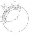
図3は、入力装置10の一部破断図であり、図4は、図3に示す破断図の一部拡大図である。また、図5は、入力装置10の殻状部22の外観図である。図5(A)には、殻状部22を斜め上方向から見た様子が示されており、図5(B)には、図5(A)に示すA方向から殻状部22を見た様子が示されている。
3 is a partially cutaway view of the
図3〜図5に示すように、入力装置10は、入力装置10の中心部に設けられた球体形状の基部21と、基部21の表面を全体的に覆うように設けられた球殻状の殻状部22と、殻状部22の表面を全体的に覆うように設けられた把持部23とを有する入力装置本体20を備える。
As shown in FIGS. 3 to 5, the
また、入力装置10は、入力装置10が所定の力以上の力で握られたことを検出するとともに、クリック感(第1の応答)を発生させるタクトスイッチ12(スイッチ部)を備える。また、入力装置10は、ユーザが入力装置10を握った力の大きさを検出する感圧センサ13(圧力センサ:握り力を検出する)を備える。
Further, the
基部21の内部は、空洞とされている。基部21内部の空洞部には、CPU11等(図6B上図参照)の電子部品が実装された回路基板が設けられる。
The inside of the
図5を参照して、殻状部22は、同一形状を有する8つのプレート25によって構成されている。それぞれのプレート25の形状は、正三角形に近い形状を有している。そして、8つのプレート25のうち、隣接する4つのプレート25の角部の頂点が1点で集中し、この頂点が集中する点が全体では、合計で6つ形成されている。この6つの点に対応する位置に、タクトスイッチ12と、感圧センサ13とがそれぞれ配置される。すなわち、本実施形態に係る入力装置10では、6つのタクトスイッチ12と、6つの感圧センサ13とを含む。
Referring to FIG. 5, the
図3及び図4を参照して、タクトスイッチ12と、感圧センサ13とは、基部21の表面と殻状部22(プレート25)の内面との間に設けられる。
3 and 4, the
感圧センサ13は、基部21の表面上に設けられており、タクトスイッチ12は、感圧センサ13上に設けられている。感圧センサ13とタクトスイッチ12との間には、第1の圧力拡散板7が介在されており、タクトスイッチ12と殻状部22(プレート25)の内面との間には、第2の圧力拡散板8が介在される。第1の圧力拡散板7及び第2の圧力拡散板8により、ユーザが把持部23を握った力を均一に感圧センサ13に伝達することができる。感圧センサ13は、入力装置本体が握られた力の大きさをセンシングする。
The
タクトスイッチ12は、スイッチ本体5と、スイッチ本体5に対して移動可能な可動部6とを有する。また、タクトスイッチ12は、内部に可動部6の移動に応じてON/OFFが切り替えられる電気的なスイッチ機構(検出部)(図示せず)を有する。また、タクトスイッチ12は、可動部6の移動に応じてクリック感を発生させる板バネ等の弾性体を用いたクリック感発生機構(第1応答部)(図示せず)を有する。
The
ここで、感圧センサ13と、プレート25に加えられる力の大きさ等との関係について説明する。感圧センサ13により検出された圧力値を基に、1つのプレート25に加えられた力の大きさと、力が加えられた位置とを算出する場合、1つのプレート25に対しては、少なくとも3つの感圧センサ13が必要である。
Here, the relationship between the
本実施形態では、1つのプレート25に対しては、プレート25に加えられた力を検出する(他のプレート25と共通で用いられる)3つの感圧センサ13が設けられている。従って、感圧センサ13からの圧力値を基に、ベクトル計算等を利用した演算が実行されることで、プレート25に加えられた力の大きさと、力が加えられた位置とを正確に算出することができる。
In the present embodiment, for one
また、8つのプレート25に対して、それぞれ3つの感圧センサ13を用いる場合、8×3で、本来、24個の感圧センサ13が必要となる。しかし、本実施形態では、感圧センサ13は、隣接する4つのプレート25の角部の頂点が集中する点に配置されており、隣接する4つのプレート25で1つの感圧センサ13が共通で用いられている。これにより、感圧センサの数は、合計で6つあれば足りることになり、入力装置10のコストの削減が実現される。
In addition, when three
このように、本実施形態では、必要最低限の感圧センサ13で、プレート25に加えられた力の大きさと、力が加えられた位置とを正確に算出することができる。
Thus, in the present embodiment, the magnitude of the force applied to the
しかしながら、感圧センサ13は、必ずしも前記したような構成とされなくともよい。例えば、感圧センサは、1つのプレート25に対して1個や2個であってもよいし、4個以上であってもよい。また、感圧センサ13は、他のプレート25と共通で用いられる形態ではなく、それぞれのプレート25に対して独立して設けられていてもよい。
However, the
典型的には、感圧センサ13は、ユーザが入力装置10を握ったときに、プレート25(殻状部22)に加えられた力を検出することができる形態であれば、どのような形態であってもよい。また、プレート25の個数(殻状部22の分割個数)についても8個に限定されない。例えば、プレート25の数は、2個や4個等であってもよい。
Typically, the pressure-
基部21及び殻状部22は、例えば、金属や樹脂等の材料により構成される。一方、把持部23は、基部21及び殻状部22よりも軟らかい材料で構成されている。把持部23に用いられる材料としては、例えば、ポリウレタン等の合成樹脂を発砲して形成されたスポンジ等が挙げられる。
The
把持部23に用いられる材料として、スポンジ等の材料が用いられることで、触感を向上させることができ、また、ユーザは、入力装置10を握る力の大きさを微調整することができる。
By using a material such as sponge as the material used for the
次に、入力装置10の電気的な構成について、図6A及び図6Bを参照しながら説明する。図6Aの上図は、入力装置10の電気的な構成を示すブロック図であり、図6Bの上図は、入力装置10の機能構成図である。
Next, the electrical configuration of the
まず、入力装置10の電気的な構成について説明する。図6Aの上図に示すように、入力装置10は、前記したタクトスイッチ12、感圧センサ13のほか、CPU(Central Processing Unit)11、3軸加速度センサ14、3軸角速度センサ15、ROM16a、RAM16b、送受信回路17、バッテリー18を備える。また、入力装置10は、LED19(Light Emitting Diode)を有していてもよい。
First, the electrical configuration of the
3軸加速度センサ14、3軸角速度センサ15、CPU11、送受信回路17、ROM(Read Only Memory)16a、RAM(Random Access Memory)16b、LED19は、図示しない回路基板上に実装される。このCPU11等の電子部品が実装された回路基板と、バッテリー18とは、基部21の内部に形成された空洞部に設けられる。
The
3軸加速度センサ14及び3軸角速度センサ15(検出部の一例)は、入力装置10の空間内での動きを検出するセンサである。3軸加速度センサ14は、互いに直交する3軸方向の加速度を検出し、検出された加速度に応じた加速度値(動き検出値の一例)をCPU11へ出力する。3軸角速度センサ15は、互いに直交する3軸回りの角速度を検出し、検出された角速度に応じた角速度値(動き検出値の一例)をCPU11へ出力する。
The
ROM16aは不揮発性のメモリであり、CPU11の処理に必要な各種のプログラムが記憶される。RAM16bは揮発性のメモリであり、CPU11の作業領域として用いられる。
The
タクトスイッチ12は、前記スイッチ機構がONの状態となったときに、CPU11へ信号を出力する。感圧センサ13は、入力装置10がユーザに握られた力の大きさに応じた圧力値をCPU11へ出力する圧力センサの一例である。
The
CPU11は、操作対象物を制御するために、3軸加速度センサ14、3軸角速度センサ15、感圧センサ13から出力された角速度値、加速度値、圧力値に基づいて、各種の演算を実行する。例えば、CPU11は、加速度値、角速度値に基づいて、入力装置10の空間内での移動量、回転量等を算出する。また、CPU11は、感圧センサ13から出力された圧力値に基づいて、入力装置10が握られた力の大きさや、力が加えられた位置等を算出する。なお、CPU11は、タクトスイッチ12のスイッチ機構からの信号が入力されている状態で、上記各種の演算を実行する。CPU11は、後述する第1演算部の機能を実行する。
The
送受信回路17は、アンテナ等を有しており、CPU11の制御に基づいて、各種の情報を制御装置50へ送信する。例えば、送受信回路17は、入力装置10の空間内での移動量、回転量の情報や、握られた力の大きさ、力が加えられた位置等の情報を制御装置50へ送信する。なお、送受信回路17は、制御装置50から送信された情報を受信することも可能である。
The transmission /
バッテリー18としては、例えば、充電式電池が用いられる。
For example, a rechargeable battery is used as the
次に、図6Bの上図を用いて入力装置10の機能構成について説明する。入力装置10は、検出部43、第1処理部41、記憶部46、第1送受信部47及び電源部48を有している。検出部43は、第1操作検出部44及び第2操作検出部45を有している。第1処理部41は、第1応答部42、第1演算部40及び第2応答部49を有している。
Next, the functional configuration of the
検出部43は、入力装置本体がユーザに所定の力以上の力で握られたことを検出する。例えば、検出部43は、入力装置本体が握られた力の大きさを検出し、握られた力の大きさに応じた握り力検出値を出力する。第1操作検出部44は、入力装置本体への第1の操作を検出する。第1の操作としては、例えば、図18に示したように、入力装置10を握る、入力装置10をテーブルから持ち上げる、入力装置10をたたく等が挙げられ、入力装置10を握る場合のみに限られない。第1操作検出部44は、例えば、入力装置本体が所定の圧力(例えば第1の閾値)以上で握られたことを検出してもよい。また、第1操作検出部44は、その検出結果に基づき握られた力の大きさに応じた握り力検出値を出力してもよい。
The detection unit 43 detects that the input device main body is gripped by the user with a force greater than or equal to a predetermined force. For example, the detection unit 43 detects the magnitude of the force with which the input device body is gripped, and outputs a gripping force detection value corresponding to the magnitude of the gripped force. The first
第1の操作を検出後、第2操作検出部45は、入力装置本体への第2の操作を検出する。第2の操作の検出は、第1の操作の検出後に行われ、同時に行われることはない。
After detecting the first operation, the second
第2の操作としては、例えば、図18に示したように、入力装置10をつかんで操作する(入力装置10をつかんで振る)等が挙げられ、入力装置10を握る場合のみに限られない。第1操作検出部44及び第2操作検出部45により検出される検出値は、感圧センサ13や3軸加速度センサ14や3軸角速度センサ15(ジャイロセンサ)によりセンシングされた値の少なくともいずれかである。第2操作検出部45は、例えば、入力装置本体が所定の圧力(第2の閾値)以上で握られたことを検出する。第2の閾値は第1の閾値より大きい値に予め定められている。
As the second operation, for example, as shown in FIG. 18, the operation is performed by grasping the input device 10 (gripping the input device 10), and is not limited to the case where the
第1応答部42は、第1の操作の検出に基づき入力装置10の第1の応答を行う。第1の応答としては、クリック音を鳴らす、入力装置10に設けられたばねにより入力装置10を持っているユーザの手に反発力を与える等が一例として挙げられる。ただし、第1の操作の検出に基づき必ずユーザに第1の応答を行う必要はない。例えば、第1応答部42は、検出部により入力装置が握られたことが検出されたとき、及び入力装置が握られたことが検出されなくなったときに第1の応答をユーザに返してもよい。第1応答部42は、少なくとも検出部により入力装置本体が握られたことが検出されたときに、第1処理部の制御によらず、ユーザに対して第1の応答を返してもよい。また、第1の応答は、基本的にCPUを介さない処理であるため即答性があるが、CPUを介してもよい。
The
第1演算部40は、前記第1の操作に応じた入力装置本体の動きに対する動き検出値に基づき、操作対象物の操作のための演算(第1の処理)を行ってもよく、前記第2の操作に応じた入力装置本体の動きに対する動き検出に基づき操作対象物の操作のための演算(第2の処理)を行ってもよい。
The
なお、第1操作検出部44は、第1演算部40を介さずに第1応答部42に応答処理を促すことができる。このため、第1応答部42から第1演算部40に第1の応答を送らずに、ユーザへクリック音による応答を行うことができる。これにより、第1応答部42によるクリック音による第1の応答を、第1演算部40による演算結果に基づく処理より速く実行させることが可能となる。しかし、これに限られず、第1の応答(例えばクリック音による応答)を第1演算部40に送り、第1演算部40の演算開始のトリガーに利用してもよい。
The first
なお、第1の処理と第2の処理とは前記操作対象物に対する異種の操作であり、同種の操作は含まない。異種の操作としては、第1の処理では入力装置10を握る力が所定の第1の閾値圧力以上になった場合にクリック音を発生させ、第2の処理では更に握りを強くして所定の第2の閾値圧力以上になった場合に各種センサによる動き検出値に基づき操作対象物の操作のための演算を実行する例が挙げられる。他の異種の操作としては、第1の処理では入力装置10を2秒間握った場合にイネーブル(入力操作OK)とし、カーソル移動操作モードに遷移し、第2の処理では再度、入力装置10を4秒間握った場合に操作対象物を選択して操作モードに入る例が挙げられる。同種の操作としては、圧力センサによる検出値を3段階のレベルで検出することにより、弱く握ったら第1の処理に遷移し、強く握ったら第2の処理に遷移する場合が挙げられる。このような同種の操作は、各実施形態の第1の処理と第2の処理には含まない。
The first process and the second process are different kinds of operations on the operation target, and do not include the same type of operations. As a different kind of operation, in the first process, a click sound is generated when the gripping force of the
なお、第1応答部42による入力装置のユーザへの第1の応答は操作対象物を制御する制御装置50へと送受信されず、第1演算部40による操作対象物の操作のための演算結果は制御装置50へと送受信される。よって、第1応答部42による第1の応答処理は、送受信処理を含まないルートであるため、送受信処理を含む第1演算部40による演算結果に基づく処理より速いという効果を有する。
Note that the first response to the user of the input device by the
第2応答部49は、前記第2の操作の検出に基づき前記入力装置の第2の応答を行う。第2の応答としては、入力装置10に取り付けられたLEDを点滅表示させたり、音声出力や力覚表示等を用いたユーザに対するフィードバックが例として挙げられる。第2の応答は、基本的にCPUを介さない処理であるため即答性があるが、CPUを介してもよい。
The
以上に説明したように、第1処理部41は、前記第1の操作の検出値又は該第1の操作に応じた入力装置本体の動きに対する動き検出値に基づき、入力装置10の第1の応答又は操作対象物への操作のための第1の処理を行い、前記第1の操作を検出後、前記第2の操作の検出又は該第2の操作に応じた入力装置本体の動きに対する動き検出値に基づき、入力装置10の第1の応答又は操作対象物への操作のための第2の処理を行う。第1処理部41は、入力装置本体の動きを検出し、前記入力装置本体の動きに応じた動き検出値を出力し、前記入力装置本体が握られたことが検出されている状態で、前記動き検出値に基づいて前記操作対象物を制御するための処理を実行してもよい。また、第1処理部は、第1処理部の制御によって、ユーザに対して前記第1の応答とは異なる第2の応答を返す第2応答部をさらに含んでいてもよい。第1処理部41は、動き検出値または握り力検出値に基づいて、第2応答部による第2の応答を制御してもよい。また、第1処理部41は、入力装置本体が握られたことが検出されている状態で、前記動きの検出値及び前記握り力検出値に基づいて前記操作対象物を制御するための処理を実行してもよい。
As described above, the first processing unit 41 uses the first operation value of the
また、第1処理部41及び制御装置側の第2処理部61では、必要に応じて両方あるいは片方において、各検出結果を用いて所望の処理を行い、第2処理部61を介して表示制御部66に結果を出力する。
Further, the first processing unit 41 and the second processing unit 61 on the control device side perform desired processing using each detection result in both or one side as necessary, and display control is performed via the second processing unit 61. The result is output to the
記憶部46は、例えば半導体メモリ、磁気ディスク、または光学ディスクなどを用いるRAM16bまたはROM16aとして実現されうる。
The
第1送受信部47は、所定の情報を入力装置10及び制御装置50間で送信又は受信する。第1送受信部47及び第2送受信部62の間は、有線又は無線にて接続されている。
The first transmission /
電源部48は、バッテリー18として例えば、充電式電池が用いられ、各部に電力を供給する。
The
なお、第1演算部40の機能は、例えば、CPU11が記憶部46に格納されたプログラムに従って動作することによって実現され得る。このプログラムは、記憶媒体に格納して提供され、図示しないドライバを介して記憶部46に読み込まれるものであってもよく、また、ネットワークからダウンロードされて記憶部46に格納されるものであってもよい。また、上記各部の機能を実現するために、CPUに代えてDSP(Digital Signal Processor)が用いられてもよい。また、上記各部の機能は、ソフトウエアを用いて動作することにより実現されてもよく、ハードウエアを用いて動作することにより実現されてもよい。
In addition, the function of the
「制御装置の構成」
次に、図6Aの下図を参照して、制御装置50の電気的な構成を説明する。制御装置50は、CPU51、ROM53a、RAM53b、送受信回路52、指示機構54を含む。
"Control Device Configuration"
Next, the electrical configuration of the
ROM53aは不揮発性のメモリであり、CPU51の処理に必要な各種のプログラムが記憶される。RAM53bは揮発性のメモリであり、CPU51の作業領域として用いられる。
The ROM 53a is a non-volatile memory and stores various programs necessary for the processing of the
送受信回路52は、アンテナ等を有しており、入力装置10から送信される各種の情報を受信する。また、送受信回路52は、入力装置10へ信号を送信することも可能である。
The transmission /
指示機構54は、例えば、キーボードであり、ユーザは、この指示機構54を介して初期設定、特種設定などの設定を行う。指示機構54は、ユーザからの各種の指示を受付け、入力された信号をCPU51へ出力する。
The
CPU51は、下記にて説明する第2演算部の処理、表示制御部の処理を行う第2処理部の機能を実行する。CPU51は、送受信回路17によって受信された各種の情報に基づいて、表示装置60に表示される操作対象物を制御する。
The
なお、表示装置60は、例えば、液晶ディスプレイや、EL(Electro-Luminescence)ディスプレイ等により構成される。表示装置60は、2次元画像を表示する形態であってもよいし、3次元画像を表示する形態であってもよい。表示装置60は、入力装置10によって操作される操作対象物を2次元的、あるいは3次元的に表示する。
The
2次元的に表示される操作対象物としては、例えば、ポインタやアイコン、ウィンドウ等のGUI等が挙げられる。3次元的に表示される操作対象物としては、3次元表示される人型、動物型のキャラクタ画像が挙げられる。なお、これらの例は、一例に過ぎず、操作対象物は、2次元的、3次元的に表示される画像であれば、どのような画像であってもよい。 Examples of the operation target displayed two-dimensionally include a GUI such as a pointer, an icon, and a window. Examples of the operation object displayed three-dimensionally include human-type and animal-type character images displayed three-dimensionally. Note that these examples are merely examples, and the operation target may be any image as long as it is an image displayed two-dimensionally or three-dimensionally.
なお、表示装置60は、テレビジョン放送等を受信可能なテレビジョン装置であってもよい。あるいは、表示装置60が操作対象物を3次元的に表示させる形態の場合、表示装置60は、ユーザが裸眼で視認することができる立体画像を表示する立体画像表示装置であってもよい。図1では、制御装置50と表示装置60とが別々の場合が示されているが、制御装置50と表示装置60とは一体的に構成されていてもよい。
Note that the
次に、図6Bの下図を用いて制御装置50の機能構成について説明する。制御装置50は、第2処理部61、記憶部63、第2送受信部62及び指示部64を有している。第2処理部61は、第2演算部65及び表示制御部66を有している。
Next, the functional configuration of the
第2送受信部62は、所定の情報を第1送受信部47に送信又は受信する。記憶部63は、例えば半導体メモリ、磁気ディスク、または光学ディスクなどを用いるRAM53bまたはROM53aとして実現されうる。
The second transmission /
例えばユーザがキーボード等の指示機構53を用いて入力操作すると、指示部64は、初期設定、特種設定などの設定を行う。具体的には、指示部64は、ユーザからの各種の指示を受付け、入力された信号を第2処理部61へ出力し、初期設定等を指示する。
For example, when the user performs an input operation using the instruction mechanism 53 such as a keyboard, the
第2演算部65は、第1処理部41からの検出結果や演算結果を用いて所望の処理を行い、表示制御部66に結果を出力する。
The
表示制御部66は、得られた情報に基づき操作対象物の表示を制御する。なお、表示制御部66の替わりに又は表示制御部66に加えて、操作対象物の表示以外の動作(例えば音や振動等)を表現できる表現部を設けてもよい。表現部では、得られた情報を用いて所望の入力操作に対して対象物の表現を制御する。
The
なお、第2演算部65及び表示制御部66の機能は、例えば、CPU51が記憶部63に格納されたプログラムに従って動作することによって実現され得る。このプログラムは、記憶媒体に格納して提供され、図示しないドライバを介して記憶部63に読み込まれるものであってもよく、また、ネットワークからダウンロードされて記憶部63に格納されるものであってもよい。また、上記各部の機能を実現するために、CPUに代えてDSP(Digital Signal Processor)が用いられてもよい。また、上記各部の機能は、ソフトウエアを用いて動作することにより実現されてもよく、ハードウエアを用いて動作することにより実現されてもよい。
The functions of the
[入力装置の動作]
次に、本実施形態に係る制御システム100の動作について説明する。図7は、本実施形態に係る制御システム100の動作を示すフローチャートである。図7の上のフローチャートは入力装置10の処理を示し、図7の下のフローチャートは制御装置50の処理を示す。
[Operation of input device]
Next, the operation of the
まず、ユーザは、入力装置10を持ち上げて、入力装置10を操作しやすい位置まで移動させる。なお、このとき、ディスプレイに表示される操作対象物は動かない(ステップ101のNO参照)。ユーザが入力装置10の操作を開始する意思を示して、入力装置本体20の把持部23を前記所定の力以上の力で握る。すると、入力装置本体20の殻状部22(プレート25)と、タクトスイッチ12の可動部6が入力装置10の中心に近づく方向に移動される。タクトスイッチ12の可動部6が入力装置10の中心に向かう方向へ移動すると、クリック感発生機構によりクリック感が発生する。
First, the user lifts the
入力装置10は、このクリック感による応答(第1の応答の一例)により、ユーザの操作対象物の操作を開始する意思に対して適切に応答することができる。そして、ユーザは、このクリック感により、操作対象物の操作が開始されることを容易に認識することができる。また、クリック感発生機構によるクリック感による応答は、CPUを介さない応答であるので、ユーザに対して素早くクリック感による応答を返すことができる。
The
タクトスイッチ12の可動部6が入力装置10の中心に向かう方向へ移動すると、前記クリック感が発生するとともに、タクトスイッチ12のスイッチ機構がONの状態となり、スイッチ機構からCPU11へ信号が入力される(ステップ101のYES)。
When the movable part 6 of the
タクトスイッチ12からの信号が入力されると、CPU11は、3軸加速度センサ14、3軸角速度センサ15から加速度値、角速度値を取得し、感圧センサ13から圧力値を取得する(ステップ102)。
When a signal from the
次に、CPU11は、加速度値、角速度値に基づいて、演算を実行し、入力装置10の(所定時間当りの)移動量、回転量を算出する(ステップ103)。また、CPU11は、圧力値に基づいて、ベクトル計算等を利用した演算を実行することで、入力装置10が握られた力の大きさ(プレート25に加えられた力の大きさ)と、力が加えられた位置とを算出する。
Next, the
次に、CPU11は、算出された各情報(入力装置10の移動量、回転量、入力装置10が握られた力の大きさ、力が加えられた位置)を送受信回路17を介して、制御装置50に送信する(ステップ104)。
Next, the
制御装置50のCPU51は、入力装置10から前記各情報が受信されたか否かを判定する(ステップ201)。入力装置10からの前記各情報が受信された場合、制御装置50のCPU51は、受信された前記各情報に基づいて、操作対象物を制御する(ステップ202)。なお、制御装置50のCPU51は、ステップ202において、受信された各情報について、さらに演算を実行し、操作対象物の制御の精度を向上させる処理を実行してもよい。
The
例えば、操作対象物が3次元的に表示されるキャラクタ画像である場合、ステップ202において、CPU51は、入力装置10の移動量、回転量の情報に基づいて、そのキャラクタ画像を3次元的に移動させたり、回転させたりする処理を実行する。また、CPU51は、握られた力の大きさの情報や、力の位置の情報に応じて、キャラクタ画像に特定の動き(例えば、ジャンプ、しゃがむ、笑う、怒る等)をさせる処理を実行する。なお、移動量、回転量、握られた力の大きさ、力の位置の情報に基づいて、操作対象物がどのように制御されるかについては、特に限定されない。
For example, when the operation target is a character image displayed in a three-dimensional manner, in step 202, the
図7に示す処理により、ユーザは、入力装置10を前記所定の力以上の力で握った状態で、入力装置10を移動させたり、回転させたり、入力装置10をさらに強く握ったり、入力装置10の特定の位置を強く押したりすることで、操作対象物に任意の動きをさせることができる。
With the processing shown in FIG. 7, the user can move or rotate the
一方、ユーザが、操作対象物の操作を(一時的に)停止させる場合、ユーザは、入力装置10を握った力を弱める。ユーザが入力装置10を握った力を弱め、握った力が上記所定の力未満の力となると、タクトスイッチ12の可動部6と、入力装置本体20の殻状部22(プレート25)とが入力装置10の中心から離れる方向に移動される。
On the other hand, when the user stops (temporarily) the operation of the operation target, the user weakens the force grasping the
タクトスイッチ12の可動部6が入力装置10の中心から離れる方向に移動すると、クリック感発生部によりクリック感が発生される。
When the movable part 6 of the
入力装置10は、このクリック感による応答により、ユーザの操作対象物の操作を停止させる意思に対して適切に応答することができる。そして、ユーザは、このクリック感により、操作対象物の操作が停止されることを容易に認識することができる。タクトスイッチ12の可動部6が入力装置10の中心から離れる方向へ移動すると、クリック感が発生するとともに、タクトスイッチ12のスイッチ機構による信号の出力が停止される。これにより、タクトスイッチ12からCPU11への信号の入力が停止され(ステップ101のNO)、操作対象物の動きが停止される。
The
以上説明したように、本実施形態では、ユーザは、入力装置10を上記所定の力以上の力で握ったり、入力装置10を握った力を弱めたりすることで、入力装置10の操作(空間操作、握った力の大きさによる操作)を操作対象物の操作に反映させるか否かを任意に切り替えることができる。
As described above, in the present embodiment, the user operates the input device 10 (space) by gripping the
また、本実施形態に係る入力装置10では、タクトスイッチ12のクリック感発生部によりユーザの操作対象物の操作を開始する意思に対して適切に応答することができる。そして、ユーザは、このクリック感により、操作対象物の操作が開始されることを容易に認識することができる。また、クリック感発生機構によるクリック感による応答は、CPU11を介さない応答であるので、ユーザに対して素早くクリック感による応答を返すことができる。
Further, in the
さらに、本実施形態では、入力装置10は、クリック感による応答により、ユーザの操作対象物の操作を停止させる意思に対して素早く応答することができる。そして、ユーザは、このクリック感により、操作対象物の操作が停止されることを容易に認識することができる。
Furthermore, in this embodiment, the
<第2実施形態>
次に、本開示の第2実施形態について説明する。なお、第2実施形態以降の説明では、上述の第1実施形態と同様の構成及び機能を有する部材等については、同一符号を付し、説明を省略し、または簡略化する。
Second Embodiment
Next, a second embodiment of the present disclosure will be described. In the description after the second embodiment, members and the like having the same configurations and functions as those of the above-described first embodiment are denoted by the same reference numerals, and description thereof is omitted or simplified.
[入力装置の構成]
図8は、第2実施形態に係る入力装置10の電気的な構成を示すブロック図である。第1実施形態に係る入力装置10の電気的な構成を示した図6Aと比較すると、図8に示すように、第2実施形態では、タクトスイッチ12の代わりにスイッチ31が設けられている点、及びこのスイッチ31に対して電気的に接続されたLED32が設けられている点で異なっている。
[Configuration of input device]
FIG. 8 is a block diagram showing an electrical configuration of the
スイッチ31は、内部にクリック感発生機構を有しない点で、上記タクトスイッチ12と異なっているが、その他の点については、上記タクトスイッチ12と同様の構成である。すなわち、スイッチ31は、スイッチ本体5と、スイッチ本体5に対して移動可能な可動部6と、可動部6の移動に応じてON/OFFが切り替えられる電気的なスイッチ機構(図示せず)とを有する。
The
LED32は、スイッチ31のスイッチ機構のON/OFFの切り替えに応じて、発光したり、消灯したりする。LED32は、基部21の内部に形成された空洞部に配置される。LED32の代わりに電球等により構成されてもよい。
The
なお、第2実施形態では、基部21、殻状部22、把持部23が透明、あるいは半透明な材料により構成される。
In the second embodiment, the
[入力装置の動作]
ユーザが入力装置10の操作を開始する意思を示して、入力装置本体20の把持部23を所定の力以上の力で握ると、スイッチ31の可動部6が入力装置10の中心に近づく方向に移動される。スイッチ31の可動部6が入力装置10の中心に近づく方向に移動されると、スイッチ31のスイッチ機構がONの状態となり、LED32が発光する。
[Operation of input device]
When the user indicates the intention to start the operation of the
第2実施形態では、このLED32の発光による応答(第1の応答)により、ユーザの操作対象物の操作を開始する意思に対して適切に応答することができる。また、この第2実施形態においても上記第1実施形態と同様に、LED32による発光による応答は、CPUを介さない応答であるので、ユーザに対して素早く応答を返すことができる。
In the second embodiment, it is possible to appropriately respond to the user's intention to start the operation of the operation target object by the response (first response) by the light emission of the
スイッチ31のスイッチ機構がONの状態となると、CPU11に対して信号が入力される。CPU11は、上記信号が入力されると、各種センサの検出値に基づいて種々の演算を実行し、演算結果を制御装置50に送信する。これにより、ユーザが上記所定の力以上の力で入力装置10を握った状態で入力装置10を操作(空間操作、入力装置10を握る力の大きさによる操作等)することで、操作対象物の動きが制御される。
When the switch mechanism of the
なお、入力装置10が上記所定の力以上の力で握られている間は、LED32は発光し続ける。
The
一方、ユーザが、ユーザが入力装置10を握った力を弱め、握った力が上記所定の力未満の力となると、スイッチ31の可動部6が入力装置10の中心から離れる方向へ移動する。これにより、スイッチ31のスイッチ機構がOFFの状態となり、LED32が消灯する。ユーザは、このLED32の消灯により、操作対象物の操作が停止されたことを容易に認識することができる。
On the other hand, when the user weakens the force with which the user grips the
[第2実施形態の変形例]
以上の説明では、スイッチ機構の切り替えに応じて、光を発生するLED32が用いられる場合について説明した。しかし、LED32の代わりに、スイッチ機構の切り替えに応じて、音(声)を発生する音(声)発生部や、振動を発生する振動部が用いられてもよい。あるいは、これらの組み合わせであってもよいし、これらと、タクトスイッチ12(クリック感発生機構)との組み合わせであってもよい。
[Modification of Second Embodiment]
In the above description, the case where the
<第3実施形態>
次に、本開示の第3実施形態について説明する。上記各実施形態では、ユーザが操作対象物の操作の開始、停止の意思を示して、所定の力で以上の力で入力装置10を握ったり、握った力を弱めたりした場合に、クリック感等による応答が入力装置10から返される場合について説明した。
<Third Embodiment>
Next, a third embodiment of the present disclosure will be described. In each of the embodiments described above, when the user indicates the intention to start or stop the operation of the operation target, and grips the
一方、第3実施形態では、クリック感等による応答に加え、ユーザが入力装置10を空間操作した場合等に、上記したクリック感等による応答とは異なる応答が入力装置10から返される点で、上記した各実施形態とは異なっている。従って、その点を中心に説明する。
On the other hand, in the third embodiment, in addition to the response due to the click feeling or the like, when the user spatially operates the
なお、本明細書中の説明では、ユーザによる操作対象物の操作の開始(及び停止)の意思に対する応答であって、ユーザが入力装置10を所定の力以上の力で握ったとき(及び握った力を弱めたとき)に入力装置10から発生するクリック感等の応答を第1の応答と呼ぶ。一方、ユーザが入力装置10を空間操作した場合等に、入力装置10から発生される応答を第2の応答と呼ぶ。
In the description in the present specification, it is a response to the user's intention to start (and stop) the operation of the operation target, and when the user grips the
また、CPU11の制御とは無関係に第1の応答を発生する部材を第1応答部、CPU11の制御によって第2の応答を発生する部材を第2応答部と呼ぶ。
A member that generates a first response regardless of the control of the
[入力装置の構成]
図9は、第3実施形態に係る入力装置10の電気的な構成を示すブロック図である。図9に示すように、第3実施形態では、CPU11に対して電気的に接続されたLED33が設けられているが、それ以外の点については、上述の第1実施形態(図6参照)と同様である。
[Configuration of input device]
FIG. 9 is a block diagram showing an electrical configuration of the
LED33(第2応答部の一例)は、CPU11の制御に応じて、クリック感とは異なる応答として、光による応答をユーザに返す部材である。例えば、LED33は、CPU11の制御に応じて、発光(単色、多色)したり、点滅(単色、多色)したりする。LED33は、基部21の内部に形成された空洞部に配置される。LED33の替わりに電球を用いてもよい。
The LED 33 (an example of a second response unit) is a member that returns a response by light to the user as a response different from the click feeling according to the control of the
なお、第3実施形態では、基部21、殻状部22、把持部23が透明、あるいは半透明な材料により構成される。
In the third embodiment, the
[入力装置の動作]
ユーザが入力装置10を所定の力以上の力で握ると、タクトスイッチ12のクリック感発生機構からクリック感が発生し、タクトスイッチ12のスイッチ機構がONの状態となる。タクトスイッチ12のスイッチ機構がONの状態となると、CPU11へ信号が入力される。
[Operation of input device]
When the user grasps the
CPU11は、スイッチ機構からの信号が入力されると、上記各センサから加速度値、角速度値、圧力値を取得し、入力装置10の移動量、回転量、入力装置10が握られた力の大きさ、力が加えられた位置等を算出する。そして、演算結果を制御装置50へ送信する。
When a signal from the switch mechanism is input, the
また、CPU11は、上記演算結果に基づいて、LED33を発光(単色、多色)させたり、点滅(単色、多色)させたりする。例えば、CPU11は、入力装置10の移動量や、回転量が所定の値よりも大きい場合に、LED33を発光(単色、多色)させり、点滅(単色、多色)させたりする。また、例えば、CPU11は、入力装置10が握られた力の大きさが所定の値よりも大きい場合や、力が加えられた位置が特定の位置である場合等に、LED33を発光(単色、多色)させたり、点滅(単色、多色)させたりする。
Further, the
なお、入力装置10の移動量、回転量、握った力の大きさ、力の位置によるLED33の発光、点滅は、ユーザが混乱しないように、発光色、点滅パターン等を異ならせてもよい。
It should be noted that the
あるいは、CPU11は、入力装置10の移動量、回転量、握られた力の大きさに応じて、多段階的に、異なる発光色、異なる点滅パターンでLED33を発光させる処理を実行してもよい。あるいは、CPU11は、力が加えられた位置に応じて、異なる発光色、異なる点滅パターンでLED33を発光させる処理を実行してもよい。
Or CPU11 may perform the process which makes LED33 light-emit with a different light emission color and a different blinking pattern in multiple steps according to the moving amount | distance of the
以上のような処理により、入力装置10は、ユーザによる入力装置10の操作(空間操作、握る力の大きさによる操作)に対して、適切に光による応答(第2の応答)を返すことができる。
Through the processing as described above, the
また、第3実施形態に係る入力装置10では、第2の応答(光)が、第1の応答(クリック感)と異なる応答とされているので、ユーザが混乱することが防止される。
Further, in the
[第3実施形態の変形例]
上述の説明では、CPU11の制御に応じて、第2の応答を発生する第2応答部の一例として、光を発生するLED33を例に挙げて説明した。しかし、第2応答部は、LED33に限られない。第2応答部の他の例としては、CPU11の制御に応じて、音(声)を発生する音(声)発生部や、振動を発生する振動部、熱を発生する発熱部等が挙げられる。あるいは、第2応答部として、CPUの制御に応じて、疑似加速度を発生させる疑似加速度発生部等が用いられてもよい。あるいは、第2応答部は、これらの組み合わせであってもよい。
[Modification of Third Embodiment]
In the above description, the
第3実施形態では、第1応答部の一例として、タクトスイッチ12(クリック感発生部)が用いられる場合について説明した。しかし、第1応答部は、第2実施形態において説明したLED32であってもよいし、音(声)発生部、振動部等であってもよい。あるいは、これらの組み合わせであってもよい。
In 3rd Embodiment, the case where the tact switch 12 (click feeling generation | occurrence | production part) was used was demonstrated as an example of a 1st response part. However, the first response unit may be the
第1応答部と、第2応答部との組み合わせは、第1の応答と、第2の応答とが異なっていれば、どのような組み合わせであってもよい。なお、例えば、第1応答部が振動部であり、第2応答部も振動部とする組み合わせも可能である。この場合、第1の応答としての振動パターンと、第2の応答としての振動パターンとを異ならせればよい。 The combination of the first response unit and the second response unit may be any combination as long as the first response and the second response are different. For example, a combination in which the first response unit is a vibration unit and the second response unit is also a vibration unit is possible. In this case, the vibration pattern as the first response may be different from the vibration pattern as the second response.
なお、第2の応答は、操作対象物の動きと同様の応答がされてもよい。例えば、操作対象物が振動した場合に、振動部が振動される処理が実行されてもよい。 The second response may be a response similar to the movement of the operation target. For example, when the operation target vibrates, a process for vibrating the vibration unit may be executed.
<第4実施形態>
次に、本開示の第4実施形態について説明する。
<Fourth embodiment>
Next, a fourth embodiment of the present disclosure will be described.
ここで、例えば、ユーザが入力装置10を上記所定の力以上の力で握った状態で、入力装置10を奥方向、手前方向へ移動させる場合に、表示装置60によって3次元的に表示された操作対象物が拡大、縮小される場合を想定する。
Here, for example, when the
この場合、ユーザの腕が伸びきってしまった場合や、ユーザの腕が縮みきってしまった場合には、ユーザは、操作対象物を拡大、縮小することができない。 In this case, when the user's arm is fully extended or the user's arm is fully contracted, the user cannot enlarge or reduce the operation target.
そこで、第4実施形態に係る入力装置10では、入力装置10がほぼ動いていないような状況でも、入力装置10が一定の大きさで握られている場合には、操作対象物の動き(拡大、縮小)を継続させる処理を実行する。
Therefore, in the
図10は、第4実施形態に係る入力装置10の処理を示すフローチャートである。入力装置10のCPU11は、入力装置10が前方、後方(ユーザの奥方向、手前方向)に一定量以上移動したかを判定する(ステップ301)。
FIG. 10 is a flowchart showing the processing of the
入力装置10が前方、後方に一定量以上移動している場合(ステップ301のYES)、次に、CPU11は、入力装置10の移動量がゼロに近い値となったか否かを判定する(ステップ302)。
If the
入力装置10の移動量がゼロに近い値となった場合(ステップ302のYES)、入力装置10が握られた力の大きさが閾値以上であるかを判定する(ステップ303)。握られた力の大きさが閾値以上である場合には(ステップ303YES)、入力装置10のCPU11は、送受信回路17を介して、制御装置50に対して、所定の大きさの移動量の情報を出力する(ステップ304)。
If the amount of movement of the
すなわち、入力装置10のCPU11は、入力装置10がほとんど移動していないような状況でも、入力装置10が強く握られている場合には、入力装置10が移動しているとみなして、所定の大きさの移動量の情報を制御装置50へ送信する。なお、もちろん、入力装置10が前後に移動している場合には、その移動量の情報が入力装置10から制御装置50へ送信される。
That is, the
制御装置50のCPU51は、移動量の情報を受信すると、移動量の情報に基づいて、例えば、3次元的に表示される操作対象物を拡大、縮小する処理を実行する。
When the
図10に示す処理により、ユーザは、腕が伸びきってしまったり、縮みきってしまったりした場合にも、入力装置10を強く握り込むことで、操作対象物を拡大、縮小させ続けることができる。なお、操作対象物の拡大、縮小を停止させる場合、ユーザは、入力装置10を握る力を弱めればよい。
With the processing shown in FIG. 10, the user can continue to enlarge or reduce the operation target object by firmly grasping the
上記した例では、入力装置10が前後方向に移動されることで、操作対象物が拡大、縮小される場合について説明したが、入力装置10の移動方向は、上下方向であってもし、左右方向であってもよい。入力装置10の移動方向は、特に、限定されない。また、上記した例では、入力装置10の移動に対して、操作対象物が拡大、縮小される場合について説明したが、入力装置10の回転に対して、操作対象物が拡大、縮小されてもよい。入力装置10の回転方向についても特に限定されない。これは、後述の第5実施形態においても同様である。
In the above-described example, the case where the operation target is enlarged or reduced by moving the
以上の説明では、操作対象物の拡大、縮小について説明したが、これに限られない。第4実施形態で説明した処理は、例えば、操作対象物の2次元的、3次元的な移動にも適用できるし、操作対象物が画面上に表示されたウィンドウである場合には、スクロール等にも適用できる。これは、後述の第5実施形態においても同様である。 In the above description, the enlargement / reduction of the operation target has been described, but the present invention is not limited to this. The processing described in the fourth embodiment can be applied to, for example, two-dimensional and three-dimensional movements of the operation target, and when the operation target is a window displayed on the screen, scrolling, etc. It can also be applied to. The same applies to a fifth embodiment described later.
<第5実施形態>
上述の第4実施形態では、入力装置10を握る力を強めることで、操作対象物の動きが継続される場合について説明した。一方、第5実施形態では、入力装置10を握る力を弱めることで、操作対象物の動きが継続される。
<Fifth Embodiment>
In the above-described fourth embodiment, the case where the movement of the operation target object is continued by increasing the force to grip the
なお、第5実施形態においても、上記第4実施形態と同様に、ユーザが入力装置10を所定の力以上の力で握った状態で、入力装置10を奥方向、手前方向へ移動させる場合に、3次元的に表示された操作対象物が拡大、縮小される場合を想定する。
In the fifth embodiment, as in the fourth embodiment, when the user moves the
図11は、第5実施形態に係る入力装置10の処理を示すフローチャートである。入力装置10のCPU11は、入力装置10が前方、後方(ユーザの奥方向、手前方向)に一定量以上移動したかを判定する(ステップ401)。
FIG. 11 is a flowchart showing the processing of the
入力装置10が前方、後方に一定量以上移動している場合(ステップ401のYES)、次に、CPU11は、入力装置10の移動量がゼロに近い値となったか否かを判定する(ステップ402)。
When the
入力装置10の移動量がゼロに近い値となった場合(ステップ402のYES)、入力装置10を握った力の大きさが閾値以下であるかを判定する(ステップ403)。握られた力の大きさが閾値以下である場合には(ステップ403YES)、入力装置10のCPU11は、送受信回路17を介して、制御装置50に対して、所定の大きさの移動量の情報を出力する(ステップ404)。
If the amount of movement of the
つまり、第4実施形態とは逆に、第5実施形態の入力装置10のCPU11は、入力装置10が握られている力が小さいとき(クリック感等が発生する力よりも大きい)、入力装置10が移動しているとみなして、所定の大きさの移動量の情報を制御装置50へ送信する。なお、もちろん、入力装置10が前後に移動している場合には、その移動量の情報が入力装置10から制御装置50へ送信される。
That is, contrary to the fourth embodiment, when the force with which the
図11に示す処理により、ユーザは、腕が伸びきってしまったり、縮みきってしまったりした場合にも、入力装置10を弱く握ることで、操作対象物を拡大、縮小させ続けることができる。なお、操作対象物の拡大、縮小を停止させる場合、ユーザは、入力装置10を握る力を強めればよい。
The process shown in FIG. 11 allows the user to continue to enlarge or reduce the operation target by grasping the
<第6実施形態>
次に、本開示の第6実施形態について説明する。なお、第6実施形態では、ユーザによる入力装置10の空間操作対する補正について説明する。
<Sixth Embodiment>
Next, a sixth embodiment of the present disclosure will be described. In the sixth embodiment, correction for a spatial operation of the
[入力装置の曲線的な動きを直線的な動きとする補正]
図12は、ユーザが入力装置10を空間内で移動させるときのユーザの意識上での入力装置10の動きと、実際の入力装置10の動きとを比較した図である。
[Correction to change the input device's curvilinear motion to linear motion]
FIG. 12 is a diagram comparing the movement of the
図12に示すように、ユーザが入力装置10を握って移動させる場合、ユーザが入力装置10を直線的に移動させているつもりでも、実際は、入力装置10は、直線的に移動していない場合が多い。この場合、入力装置10は、実際には、曲線的に移動しながら回転しており、回転による誤差が生じる。
As shown in FIG. 12, when the user grasps and moves the
そこで、入力装置10のCPU11は、加速度センサ14からの出力(加速度値)から入力装置10の移動量を算出する場合に、角速度センサ15からの出力(角速度値)を利用して、上記移動量を補正する処理を実行してもよい。すなわち、入力装置10のCPU11は、入力装置10の移動量算出時に、角速度センサ15の出力を利用して、入力装置10の曲線的な移動量を直線的な移動量に補正する。
Therefore, the
なお、入力装置10の回転は、微小な回転である場合が多いので、上記補正は、この微小な回転が考慮される。
Since the rotation of the
上記補正により、入力装置10の動きをユーザの意識上の入力装置10の動きに近づけるように補正することができるので、操作対象物の動きをユーザの意識上の動きに近づけることができる。これにより、ユーザは、入力装置10を用いて、好適に操作対象物を操作することができる。
By the above correction, the movement of the
[速度を一定とする補正]
ユーザが入力装置10を握って移動させる場合、ユーザが入力装置10を等速度で移動させているつもりでも、実際は、入力装置10を等速度で移動させることができない場合が多い。
[Correction to keep speed constant]
When the user grasps and moves the
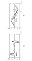
図13は、機械によって入力装置10を等速度で移動させた場合の加速度センサ14の出力波形(図13(A))と、ユーザが入力装置10を等速度で移動させようとして、入力装置10を移動させた場合の加速度センサ14の出力波形(図13(B))とを比較する図である。
FIG. 13 shows an output waveform (FIG. 13A) of the
図13(A)に示すように、機械によって入力装置10が移動させる場合、入力装置10は、急激に加速されて動き出し、短い時間で等速度状態に達し、その後、急激に減速されて停止される。一方、図13(B)に示すように、ユーザによって入力装置10が移動される場合、入力装置10は、緩やかに加速されて動き出し、緩やかに減速されて停止される。また、図11(B)に示すように、ユーザが入力装置10を等速度で移動させているつもりでも、入力装置10は、等速度で移動されていない。
As shown in FIG. 13A, when the
そこで、入力装置10に内蔵されたCPU11は、加速度センサ14の出力を補正することで、入力装置10の速度(移動量)を一定とする補正を実行してもよい。これにより、入力装置10の速度(移動量)をユーザの意識上の入力装置10の速度に近づけるように補正することができるので、ユーザは、入力装置10を用いて、好適に操作対象物を操作することができる。
Therefore, the
[角速度を一定とする補正]
図14は、ユーザが入力装置10を等角速度で回転させようとして、入力装置10を回転させた場合の角速度センサ15の出力波形を示す図である。
[Correction to keep angular velocity constant]
FIG. 14 is a diagram illustrating an output waveform of the
ユーザが入力装置10を握って回転させる場合、ユーザが等角速度で入力装置10を回転させているつもりであっても、実際には、入力装置10を等角速度で移動できていない場合が多い。
When the user grasps and rotates the
そこで、入力装置10のCPU11は、角速度センサ15の出力を補正することで、入力装置10の角速度(回転量)を一定とする補正を実行してもよい。
Therefore, the
これにより、入力装置10の角速度(回転量)をユーザの意識上の角速度に近づけるように補正することができるので、ユーザは、入力装置10を用いて、好適に操作対象物を操作することができる。
As a result, the angular velocity (rotation amount) of the
以上、第1〜第6実施形態では、入力装置を握ったまま操作することを前提としたが、次に説明する第7及び第8実施形態では、入力装置を握ったまま操作することを前提としなくてもよい。また、第1〜第6実施形態では、第1の応答(例えばクリック応答)を前提としたが、第7及び第8実施形態では、第1の応答を前提としなくてもよい。さらに、第7及び第8実施形態では、第1の応答は、特定位置のボタンを押すという概念でなくてもよく入力装置のどこを握ってもその操作を検出する。
<第7実施形態>
[入力装置の動作]
まず、第7実施形態に係る入力装置10の動作について説明する。図15及び図16は、本実施形態に係る入力装置10の動作を示すフローチャートである。
As described above, in the first to sixth embodiments, it is assumed that the operation is performed while holding the input device. However, in the seventh and eighth embodiments described below, it is assumed that the operation is performed while holding the input device. You do not have to. In the first to sixth embodiments, the first response (for example, click response) is assumed. However, in the seventh and eighth embodiments, the first response may not be assumed. Further, in the seventh and eighth embodiments, the first response may not be a concept of pressing a button at a specific position, and the operation is detected regardless of where the input device is gripped.
<Seventh embodiment>
[Operation of input device]
First, the operation of the
まず、第1操作検出部44は、感圧センサ13を用いて圧力を検出し、検出値と所与の第1の閾値を比較して、ユーザによる入力装置10の握り圧力が第1の閾値を上回ったかを判定し(ステップ501)、上回るまでステップ501の処理を繰り返す。握り圧力が第1の閾値を上回ったと判定された場合、第1応答部42は、第1の応答を返す(ステップ502)。
First, the first
その後、第2操作検出部45は、感圧センサ13を用いて圧力を検出し、検出値と所与の第2の閾値を比較して、握り圧力が第2の閾値を上回ったかを判定し(ステップ503)、上回るまでステップ503の処理を繰り返す。握り圧力が第2の閾値を上回ったと判定された場合、イネーブル状態に遷移し(ステップ504)、第2操作検出部45は、加速度センサ14、角速度センサ15、感圧センサ13を用いてユーザ操作に対する加速度、角速度、圧力値を検出する(ステップ505)。
Thereafter, the second
次に、第2操作検出部45は、感圧センサ13を用いて圧力を検出し、検出値と所与の第2の閾値を比較して、握り圧力が第2の閾値を下回ったかを判定する(ステップ506)。下回っていないと判定された場合、第1演算部40は、ステップ505にて検出した各検出値に基づき、入力装置10に対する操作量(入力装置10の移動量、回転量、握り量)を演算する(ステップ507)。第1送受信部47は、演算された操作量に関する各情報を制御装置50の第2送受信部62に送信し(ステップ508)、ステップ505に戻る。
Next, the second
一方、ステップ506にて下回ったと判定された場合、ディスエーブル状態に遷移する(ステップ509)。第1操作検出部44は、更に感圧センサ13からの検出値が第1の閾値を下回ったかを判定し(ステップ510)、下回ったと判定された場合、第2応答部49は、第2の応答を返し(ステップ511)、本処理を終了する。
On the other hand, if it is determined in step 506 that the value has fallen below, a transition is made to the disabled state (step 509). The first
これによれば、タクトスイッチ12のオン/オフの切り替えを行うことなく、操作対象物に対する入力操作をスムーズに実現することができる。以下では、図16のフローチャートを用いて本実施形態の具体的動作の一例について詳細に説明する。
According to this, it is possible to smoothly realize the input operation on the operation target without switching the
まず、ステップ501と同様に、第1操作検出部44は、感圧センサ13を用いて圧力を検出し、検出値と所与の第1の閾値を比較して、ユーザによる入力装置10の握り圧力が第1の閾値を上回ったかを判定する(ステップ601)。握り圧力が第1の閾値を上回ったと判定された場合、第1応答部42は、第1の応答を返す(ステップ602)。第1の応答は、ユーザに入力操作の許可を示すクリック音であってもよく、入力装置10から発生した反発力であってもよい。
First, similarly to step 501, the first
その後、第2操作検出部45は、ステップ503と同様に、感圧センサ13を用いて圧力を検出し、検出値と所与の第2の閾値を比較して、握り圧力が第2の閾値を上回ったかを判定する(ステップ603)。握り圧力が第2の閾値を上回った判定された場合、第2操作検出部45は、イネーブル信号を出力して演算有効状態に遷移し、ユーザが行った入力装置10を握る、動かす、回す等の操作に対して、加速度センサ14、角速度センサ15、感圧センサ13を用いて加速度、角速度、圧力値を検出する(ステップ604)。
Thereafter, similarly to step 503, the second
次に、第1演算部40は、ステップ604にて検出した各検出値に基づき、入力装置10の移動量、回転量、握り量、力が加わった位置を演算する(ステップ605)。第1送受信部47は、演算された移動量、回転量、握り量、力が加わった位置を制御装置50の第2送受信部62に送信する(ステップ606)。
Next, the
次に、第2操作検出部45は、感圧センサ13を用いて更に入力装置10への握り圧力を検出し、検出値に変化があったかを判定する(ステップ607)。変化がないと判定された場合、第1演算部40は、操作対象物の移動量を演算された移動量にキープする(ステップ608)。一方、圧力が小さくなったと判定された場合、第1演算部40は、操作対象物の移動量を小さくし(ステップ609)、圧力が大きくなったと判定された場合、第1演算部40は、操作対象物の移動量を大きくする(ステップ610)。
Next, the second
次に、第2操作検出部45は、感圧センサ13を用いて握り圧力を検出し、検出値と所与の第2の閾値を比較して、握り圧力が第2の閾値を下回ったかを判定する(ステップ611)。下回っていないと判定された場合、ステップ607に戻り、ステップ607〜611の処理を繰り返す。
Next, the second
ここでは、ユーザは握りを放しているため、ステップ611にて下回っていると判定される。この場合、第2操作検出部45は、ディスエーブル信号を出力して演算無効状態に遷移する(ステップ612)。第1操作検出部44は、更に感圧センサ13からの検出値が第1の閾値を下回ったかを判定し(ステップ613)、下回ったと判定された場合、第2応答部49は、第2の応答を返し(ステップ614)、本処理を終了する。第2の応答は、ユーザに入力操作の終了を示すクリック音であってもよく、入力装置10から発生した反発力であってもよい。
Here, since the user has released the handgrip, it is determined in step 611 that it is lower. In this case, the second
本実施形態によれば、ユーザが操作対象物を思い通りに操作可能な入力装置、入力方法及び制御システムを提供することにより、ユーザに操作の心地よさ、快適さを与えることができる。また、本実施形態によれば、タクトスイッチ12のオン/オフの切り替えを行うことなく、操作対象物に対する入力操作をスムーズに実現することができる。また、本実施形態では、ユーザは、入力装置10を握り続けながら操作する必要はなく、握らない状態で回転、移動の操作ができる。これにより、ユーザの入力操作が楽になり、疲れることなく快適に操作対象物を遠隔操作することができる。
According to this embodiment, by providing an input device, an input method, and a control system that allow a user to operate an operation target as desired, it is possible to give the user comfort and comfort. Further, according to the present embodiment, it is possible to smoothly realize the input operation on the operation target without switching the
なお、イネーブル信号を出力したとき、必要に応じて計算値の安定化のためのキャリブレーション等を行ってもよい。また、ディスエーブル信号の出力のタイミングと、第2の応答(たとえばクリック音)のタイミングは同時でもよく適宜ずらしてもよい。また、第1の応答及び第2の応答は、発しなくてもよい。 When the enable signal is output, calibration for stabilizing the calculated value may be performed as necessary. The timing of outputting the disable signal and the timing of the second response (for example, click sound) may be the same or may be appropriately shifted. Further, the first response and the second response may not be issued.
<第8実施形態>
[入力装置の動作]
次に、第8実施形態に係る入力装置10の動作について説明する。図17は、本実施形態に係る入力装置10の動作を示すフローチャートである。
<Eighth Embodiment>
[Operation of input device]
Next, the operation of the
まず、第1操作検出部44は、感圧センサ13を用いて圧力を検出し、検出値から入力装置10がテーブルから持ち上げられたかを判定し(ステップ701)、テーブルから持ち上げられるまでステップ701の処理を繰り返す。テーブルから持ち上げられた場合、イネーブル状態に遷移し(ステップ702)、第1操作検出部44は、第1操作を検出する(ステップ703)。第1操作としては、例えば加速度センサ14、角速度センサ15、感圧センサ13を用いてユーザ操作に対する加速度、角速度、圧力値を検出することが挙げられる。ここでは、ユーザは入力装置10の握りを緩めたのち、入力装置10を移動させる動作を行っている。よって、第1操作検出部44は、加速度センサ14から加速度を検出し、第1演算部40は検出された加速度に基づき例えばカーソル移動量を算出する。次に、第1送受信部47は、第1操作(カーソル移動)のための情報(カーソル移動量)を制御装置50へ送信する(ステップ704)。
First, the first
次に、第2操作検出部45は、感圧センサ13を用いて圧力を検出し、検出値に基づき入力装置10が4秒間握られたかを判定し(ステップ705)、4秒間握られるまでステップ705の処理を繰り返す。4秒間握られたと判定された場合、第2操作検出部45は、第2操作を検出する(ステップ706)。第2操作としては、例えば加速度センサ14、角速度センサ15、感圧センサ13を用いてユーザ操作に対する加速度、角速度、圧力値を検出することが挙げられる。ここでは、ユーザは入力装置10の握りを緩めたのち、入力装置10を回しながら移動させる動作を行っている。よって、第2操作検出部45は、加速度センサ14及び角速度センサ15から加速度及び角速度を検出し、第1演算部40は検出された加速度及び角速度に基づき回転量、移動量を算出する。次に、第1送受信部47は、第2操作(操作対象物の操作)のための情報(回転量、移動量)を制御装置50へ送信する(ステップ707)。
Next, the second
次に、第1操作検出部44は、感圧センサ13を用いて握り圧力を検出し、入力装置10がテーブルに置かれているかを判定する(ステップ708)。ここでは、ユーザは握りを放しており、入力装置10はテーブルに置かれた状態になっている。よって、この場合、第1操作検出部44は、入力装置10に対する入力操作は終了したと判定し、本処理を終了する。
Next, the first
なお、第1操作を検出するための第1アクションとしてのステップ701の判定は、上記判定に限らず、例えば、入力装置10がたたかれたかの判定、入力装置10が2回(又は2秒間等)握られたかの判定等様々な判定方法を用いることができる。
Note that the determination in step 701 as the first action for detecting the first operation is not limited to the above determination. For example, the determination as to whether the
また、第2操作を検出するための第2アクションとしてのステップ705の判定も同様に様々な判定方法を用いることができる。また、第2操作の検出は、上記検出内容に限られず、例えば、操作対象物を回すために入力装置10を回転させてもよいし、操作対象物を移動させるために入力装置10を左右に動かしてもよいし、操作対象物をズームするために入力装置10を前後に動かしてもよい。
Similarly, various determination methods can be used for the determination in step 705 as the second action for detecting the second operation. In addition, the detection of the second operation is not limited to the above-described detection content. For example, the
本実施形態では、ユーザは、入力装置10を握り続けながら操作する必要はなく、握らない状態で回転、移動等の操作をすることができる。これにより、ユーザの入力操作が楽になり、疲れることなく快適に操作対象物を遠隔操作することができる。
In the present embodiment, the user does not need to operate the
また、上記動作は、アプリケーションのモードをイネーブル、ディスエーブルとする場合においては、選択された第1操作検出部44の検出結果を用いて判定する。これにより、アプリケーションの動作時と停止時という一連の動作を行うにあたり、より直感的な操作を実現することができる。
The operation is determined using the detection result of the selected first
[第1操作、第2操作例]
なお、操作対象物の操作と入力装置10の操作との関係は上記に説明した第1の操作、第2の操作と操作対象物の操作との関係に限られない。
[First operation, second operation example]
The relationship between the operation of the operation target and the operation of the
例えば、図18に第1操作例及び第2操作例を示す。第1操作例としては、ユーザ操作が、
例1.入力装置10をテーブルから持ち上げる、
例2.入力装置10をたたく、
例3.入力装置10を指定回数(例えば2回)握る、
例4.入力装置10を指定時間(例えば2秒間)握る、
の場合、第1操作検出部44は、第1操作を検出したと判定してもよい。この場合、表示装置60のディスプレイ60aではカーソルが移動する等の操作が行われる。
For example, FIG. 18 shows a first operation example and a second operation example. As a first operation example, a user operation is
Example 1. Lifting the
Example 2. Strike the
Example 3 Hold the input device 10 a specified number of times (for example, twice),
Example 4 Hold the
In this case, the first
また、第2操作例としては、ユーザによる入力装置10の操作が、入力装置10をつかんで操作した場合(入力装置10をつかんで振る等)、第2操作検出部45は、第2操作を検出したと判定してもよい。この場合、所定のアプリケーションを起動する等の操作が行われる。
As a second operation example, when the user operates the
また、図19の上図には、単一アプリケーションの場合の第1操作例及び第2操作例、図19の下図には、複数アプリケーションの場合の第1操作例及び第2操作例を示す。 19 shows a first operation example and a second operation example in the case of a single application, and the lower diagram in FIG. 19 shows a first operation example and a second operation example in the case of a plurality of applications.
図19の上図に示した単一アプリケーションの場合の第1操作例としては、ユーザ操作が、
例1.入力装置10をテーブルから持ち上げる、
例2.入力装置10を指定回数(例えば3回)握る、
等が挙げられる。この場合、第1操作検出部44は、第1操作を検出したと判定する。その結果、所定のアプリケーションが起動され、スタンバイ状態となる。一例としては、地図情報のアプリケーションが起動され、表示装置60のディスプレイ60aに地図情報が操作可能に表示される。
As a first operation example in the case of the single application shown in the upper diagram of FIG.
Example 1. Lifting the
Example 2. Hold the input device 10 a specified number of times (for example, 3 times),
Etc. In this case, the first
また、第2操作例としては、ユーザによる入力装置10の操作が、入力装置10をつかんで操作した場合(入力装置10をつかんで振る等)、第2操作検出部45は、第2操作を検出したと判定する。その結果、所定のアプリケーションが操作される。例えば、ディスプレイ60aに表示された地図情報が操作される(同一アプリケーション)。
As a second operation example, when the user operates the
図19の下図に示した複数アプリケーションの場合の第1操作例としては、ユーザによる入力装置10の操作が、入力装置10をつかんで操作した場合(入力装置10をつかんで振る等)、第2操作検出部45は、第1操作を検出したと判定する。その結果、所定のアプリケーションが操作される。例えば、ディスプレイ60aに表示された地図情報が操作される。
As a first operation example in the case of a plurality of applications shown in the lower diagram of FIG. 19, when the operation of the
また、第2操作例としては、ユーザ操作が、
例1.入力装置10をテーブルから持ち上げる、
例2.入力装置10を指定回数(例えば3回)握る、
等が挙げられる。この場合、別のアプリケーションが起動される。一例としては、ガイド情報のアプリケーションが起動されて、ディスプレイ60aにガイド情報が表示される(異なるアプリケーション)。
As a second operation example, a user operation is
Example 1. Lifting the
Example 2. Hold the input device 10 a specified number of times (for example, 3 times),
Etc. In this case, another application is activated. As an example, the guide information application is activated and the guide information is displayed on the display 60a (different application).
その他、操作対象物の操作と入力装置10の操作との関係には次のようなものも考えられる。次の入力装置10の操作は第1の操作であってもよく、第2の操作であってもよい。
In addition, the following may be considered as the relationship between the operation of the operation target and the operation of the
・操作対象物がディスプレイに表示されたまま動かない場合、入力装置10がテーブル等に置かれたまま、ユーザはなんら操作しない。
・操作対象物に触りたい場合、ユーザは入力装置10を持ち上げ手元に持つ。
・操作対象物に近づきたい場合、ユーザは入力装置10を動かし、カーソル移動モードにする。
When the operation target is not moved while being displayed on the display, the user does not perform any operation while the
When the user wants to touch the operation target, the user lifts the
When the user wants to approach the operation target, the user moves the
・操作対象物を掴みたい場合、ユーザは、センサにより一定以上のセンサ量が検出される程度に入力装置10を握る。
・操作対象物を操作する場合、ユーザは入力装置10を回りたり、左右に動かす。
・操作対象物をじっくり見る場合、ユーザは入力装置10を前後に動かしてズームイン/ズームアウトの操作を行う。
When the user wants to grasp the operation target, the user holds the
-When operating the operation target, the user turns the
When viewing the operation target carefully, the user moves the
・操作対象物を放す場合、ユーザは入力装置10をテーブル等の元の位置に置く。
When releasing the operation target, the user places the
(効果)
以上に説明した各実施形態によれば、操作対象物の操作に当たり、ユーザが手や足等を用いて直接に入力装置を操作することにより、より好適に操作対象物を操作することができる。例えば、入力装置10を握ったり、回転させたりする操作により、より直感的に操作対象物を操作することができる。特に、第1の操作検出→応答又は対象物操作演算→第2の操作検出→対象物操作演算という、ユーザの意思に則した連続的な操作をスピーディに行うことができる。
(effect)
According to each embodiment described above, when operating the operation target, the user can operate the operation target more suitably by directly operating the input device using a hand or a foot. For example, the operation target can be more intuitively operated by an operation of grasping or rotating the
また、センサと人間による入力操作によって大きく変形する物質(入力装置本体)とを接触させない構成とすることにより、入力装置本体に耐久性を持たせることができる。 Moreover, durability can be given to an input device main body by making it the structure which does not contact the substance (input device main body) which deform | transforms greatly by input operation by a human.
特に、人間が手を用いて入力装置10を操作する場合において、握るという行為を、遠隔に表示されている操作対象物を握るという結果と連動させることにより、より直感的な操作を実現することができる。
In particular, when a human uses the hand to operate the
また、クリック音等の第1応答と、圧力センサの検出値を用いた所定圧力の設定という2つの手段によって、仮想空間の操作対象物を握る(掴む、選択する)と対応付けることにより、より直感的な操作を実現することができる。 Further, by grasping (grabbing, selecting) the operation object in the virtual space by two means of the first response such as a click sound and the setting of the predetermined pressure using the detection value of the pressure sensor, it is more intuitive. Operation can be realized.
また、上記各実施形態では、検出部43が複数のセンサからの検出値を取得可能なように構成したので。これにより、例えば、第1操作検出部44の検出結果を用いて、アプリケーションのモードをイネーブルとし、イネーブル後の動作状態で第2操作検出部45が複数の検出値から必要な検出値を選択した結果を用いて、対象物を操作するための情報を出力する。これによっても、より直感的な操作を実現することができる。
Moreover, in each said embodiment, since the detection part 43 was comprised so that the detection value from a some sensor was acquirable. Thereby, for example, the application mode is enabled using the detection result of the first
以上、添付図面を参照しながら本開示の好適な実施形態について詳細に説明したが、本開示の技術的範囲はかかる例に限定されない。本開示の技術分野における通常の知識を有する者であれば、特許請求の範囲に記載された技術的思想の範疇において、各種の変更例または修正例に想到し得ることは明らかであり、これらについても、当然に本開示の技術的範囲に属するものと了解される。 The preferred embodiments of the present disclosure have been described in detail above with reference to the accompanying drawings, but the technical scope of the present disclosure is not limited to such examples. It is obvious that a person having ordinary knowledge in the technical field of the present disclosure can come up with various changes or modifications within the scope of the technical idea described in the claims. Of course, it is understood that it belongs to the technical scope of the present disclosure.
[各種変形例]
例えば、上記入力装置10を用いて、テレビジョン装置のリモートコントローラに設けられているような十字キーの入力と同様の入力をさせることもできる。この場合、ユーザにより入力装置10が上下左右に回転された場合に、十字キーの上下左右キーが押されたことに相当する処理が実行されてもよい。
[Variations]
For example, the
また、ユーザにより入力装置10が強く握られた状態で、入力装置10が上下左右に移動されることで、十字キーの上下左右キーが連続して押されたことに相当する処理が実行されてもよい。あるいは、ユーザにより入力装置10が上下左右方向に移動された後に、入力装置10が握った力が弱められ、再び入力装置10が握られたときに、十字入力キーの上下左右キーが連続して押されたことに相当する処理が実行されてもよい。なお、この場合、入力装置10が握った力を弱めるときにクリック感が発生し、かつ、再び入力装置10が握られたときにもクリック感が発生する。
In addition, when the
以上の説明では、入力装置10が無線である場合について説明したが、有線であってもよい。
Although the case where the
以上の説明では、入力装置10の基部21、殻状部22、把持部23が球状である場合について説明したが、これらは、多面体であってもよい。
In the above description, the case where the
以上の説明では、感圧センサ13を例に挙げて説明したが、感圧センサ13の代わりに、静電センサが用いられてもよい。
In the above description, the
静電センサは、例えば、距離に応じて静電容量の変化を読み取ることができる構成とされる。静電センサは、ユーザが入力装置10を握った際の手の近接量を検出することで、入力装置10が握られた力の大きさを検出することができる。この静電センサは、例えば、球体、多面体の形状とされる。静電センサは、把持部23とは接触しないように構成される。これにより、手の操作による摩擦等の劣化を防止することができる。
For example, the electrostatic sensor is configured to be able to read a change in capacitance according to a distance. The electrostatic sensor can detect the magnitude of the force with which the
なお、感圧センサ13と、静電センサとが両方とも用いられてもよい。この場合、例えば、感圧センサ13で検知できないさらに微小な大きさの力を静電センサで検出することで、より高感度な(検出レンジの広い)センサ構成が実現される。
Note that both the pressure-
入力装置10は、ユーザにより入力装置10が空間内で移動、回転されたときに、この移動、回転に応じて発電可能な発電デバイス(図示せず)を備えていてもよい。あるいは、入力装置10は、外部からの電磁波により発電するループコイル等を備えていてもよい。この発電デバイス、ループコイルにより発電された電力は、バッテリー18に充電される。これにより、ユーザは、バッテリー18を交換する必要がなくなる。
The
上述の例では、検出部としての3軸加速度センサ14、3軸角速度センサ15と、握り力検出部としての感圧センサ13及び/または静電センサとが用いられる場合について説明した。ここで、検出部は、3軸加速度センサ14、3軸角速度センサ15に限られない。例えば、検出部の他の例として、速度センサ(例えば、ピトー管)、角度センサ(例えば、地磁気センサ)、角加速度センサ等が挙げられる。また、上記した例では、検出部は動きを検出し、かつ握りを検出する場合について説明したが、いずれか一方であってもよい(第4、5実施形態を除く)。
In the above-described example, the case where the three-
以上の説明では、操作対象物がディスプレイに2次元的、3次元的に表示される画像であるとして説明したが、操作対象物は、これに限られない。例えば、搬送ロボットや、人型ロボット等の現実の物体であってもよい。 In the above description, the operation target is described as an image displayed two-dimensionally and three-dimensionally on the display, but the operation target is not limited to this. For example, it may be a real object such as a transfer robot or a humanoid robot.
なお、以下のような構成も本開示の技術的範囲に属する。
(1) 操作対象物を操作するための入力操作がなされる入力装置本体と、
前記入力装置本体への第1の操作を検出する第1操作検出部と、
前記第1の操作を検出後、前記入力装置本体への第2の操作を検出する第2操作検出部と、
前記第1の操作の検出値又は該第1の操作に応じた前記入力装置本体の動きに対する動き検出値に基づき、前記入力装置の第1の応答又は前記操作対象物への操作のための第1の処理を行う第1処理部と、を備え、
前記第1の操作を検出後、前記第2の操作の検出値又は該第2の操作に応じた前記入力装置本体の動きに対する動き検出値に基づき、前記入力装置の第1の応答又は前記操作対象物への操作のための第2の処理を行う入力装置。を備える入力装置。
(2) 前記第1操作検出部及び前記第2操作検出部は、前記入力装置本体が所定の圧力以上で握られたことを検出する前記(1)に記載の入力装置。
(3)前記第1の処理部は、前記第1の操作の検出に基づき前記入力装置の第1の応答を行う第1応答部と、前記第2の操作に応じた前記入力装置本体の動きに対する動き検出値に基づき前記操作対象物の操作のための演算を行う第1演算部と、を含む前記(1)又は(2)に記載の入力装置。
(4) 前記第1応答部による前記入力装置の第1の応答は前記操作対象物を制御する制御装置へと送受信されず、前記第1演算部による前記操作対象物の操作のための演算結果は制御装置へと送受信される前記(3)に記載の入力装置。
(5) 前記第1応答部による前記第1の応答処理は、前記第1演算部による前記演算結果に基づく処理より速い前記(4)に記載の入力装置。
(6) 前記第1の処理と前記第2の処理とは異種の操作である前記(1)〜(5)のいずれか一項に記載の入力装置。
(7) 前記第1の処理部は、前記第1の操作に応じた前記入力装置本体の動きに対する動き検出に基づき前記操作対象物の操作のための演算を行う第1演算部と、前記第2の操作の検出に基づき前記入力装置の第2の応答を行う第2応答部と、を含む前記(1)又は(2)に記載の入力装置。
(8) 操作対象物を操作するための入力操作がなされる入力装置本体への第1の操作を検出することと、
前記第1の操作を検出後、前記入力装置本体への第2の操作を検出することと、
前記第1の操作の検出値又は該第1の操作に応じた前記入力装置本体の動きに対する動き検出値に基づき、前記入力装置の第1の応答又は前記操作対象物への操作のための第1の処理を行うことと、
前記第1の操作を検出後、前記第2の操作の検出値又は該第2の操作に応じた前記入力装置本体の動きに対する動き検出値に基づき、前記入力装置の第1の応答又は前記操作対象物への操作のための第2の処理を行うこと、
を含む入力方法。
(9) 操作対象物を操作するための入力操作がなされる入力装置本体と、
前記入力装置本体への第1の操作を検出する第1操作検出部と、
前記第1の操作を検出後、前記入力装置本体への第2の操作を検出する第2操作検出部と、
前記第1の操作の検出値又は該第1の操作に応じた前記入力装置本体の動きに対する動き検出値に基づき、前記入力装置の第1の応答又は前記操作対象物への操作のための第1の処理を行う第1処理部と、を有する入力装置と、
前記入力装置の操作に応じて前記操作対象物を制御する制御装置と、を備え、
前記入力装置は、前記第1の操作を検出後、前記第2の操作の検出値又は該第2の操作に応じた前記入力装置本体の動きに対する動き検出値に基づき、前記入力装置の第1の応答又は前記操作対象物への操作のための第2の処理を行い、
前記制御装置は、前記入力装置により行われた第1の処理又は第2の処理に応じて、前記操作対象物を制御する制御システム。
(10) 前記第1又は第2操作検出部は、前記入力装置本体がユーザに所定の力以上の力で握られたことを検出し、
前記第1処理部は、前記入力装置本体の動きを検出し、前記入力装置本体の動きに応じた動き検出値を出力し、前記入力装置本体が握られたことが検出されている状態で、前記動き検出値に基づいて前記操作対象物を制御するための処理を実行し、
前記第1応答部は、少なくとも前記検出部により前記入力装置本体が握られたことが検出されたときに、前記第1処理部の制御によらず、ユーザに対して第1の応答を返す(3)に記載の入力装置。
(11) 前記(1)〜(10)に記載の入力装置であって、
前記入力装置本体は、
表面を有する基部と、
表面と、前記基部の表面と間隙を開けて対向する内面とを有し、前記基部の表面を覆うように設けられた殻状部とを有し、
前記入力装置は、前記基部の表面と、前記殻状部の内面との間に設けられたスイッチ部をさらに具備し、
前記検出部は、前記スイッチ部の一部を構成するスイッチ機構であり、
前記第1応答部は、前記第1の応答としてクリック感を発生する、前記スイッチ部の一部を構成するクリック感発生機構である入力装置。
(12) 前記(11)に記載の入力装置であって、
前記検出部は、前記基部の表面と、前記スイッチ部との間に設けられ、前記入力装置が握られた力の大きさを検出し、握られた力の大きさに応じた検出値を出力する入力装置。
(13) 前記(12)に記載の入力装置であって、
前記入力装置本体は、前記殻状部の表面を覆うように設けられ、前記基部及び前記殻状部よりも軟らかい材料で構成された把持部をさらに有する入力装置。
(14) 前記(10)〜(13)のいずれか一項に記載の入力装置であって、
前記第1応答部は、前記検出部により前記入力装置が握られたことが検出されたとき、及び入力装置が握られたことが検出されなくなったときに前記第1の応答をユーザに返す入力装置。
(15) 前記(10)〜(14)のいずれか一項に記載の入力装置であって、
前記第1処理部は、該第1処理部の制御によって、ユーザに対して前記第1の応答とは異なる第2の応答を返す第2応答部をさらに具備する入力装置。
(16) 前記(15)に記載の入力装置であって、
前記検出部は、前記入力装置が握られた力の大きさを検出し、握られた力の大きさに応じた握り力検出値を出力し、
前記第1処理部は、前記動き検出値、または前記握り力検出値に基づいて、前記第2応答部による第2の応答を制御する入力装置。
(17) 前記(10)〜(16)のいずれか一項に記載の入力装置であって、
前記検出部は、前記入力装置本体が握られた力の大きさを検出し、握られた力の大きさに応じた握り力検出値を出力し、
前記第1処理部は、入力装置本体が握られたことが検出されている状態で、前記動きの検出値及び前記握り力検出値に基づいて前記操作対象物を制御するための処理を実行する入力装置。
(18) 前記(17)に記載の入力装置であって、
前記第1処理部は、前記動き検出値がゼロに近い値を示した場合に、前記握り力検出値に基づいて、前記操作対象物の動きを継続させる処理を実行する入力装置。
(19) 前記第1又は第2操作検出部は、前記入力装置本体がユーザに所定の力以上の力で握られたことを検出し、
前記第1処理部は、前記入力装置が握られた力の大きさを検出し、握られた力の大きさに応じた握り力検出値を出力し、前記検出部により前記入力装置本体が握られたことが検出されている状態で、前記握り力検出値に基づいて前記操作対象物を制御するための処理を実行し、
前記第1応答部は、少なくとも前記検出部により前記入力装置本体が握られたことが検出されたときに、前記第1処理部の制御によらず、ユーザに対して第1の応答を返す(3)に記載の入力装置。
The following configurations also belong to the technical scope of the present disclosure.
(1) an input device body on which an input operation for operating an operation target is performed;
A first operation detection unit for detecting a first operation on the input device body;
A second operation detection unit for detecting a second operation on the input device main body after detecting the first operation;
Based on a detected value of the first operation or a detected value of movement of the input device main body in response to the first operation, a first response of the input device or a first for an operation on the operation object. A first processing unit that performs the processing of 1;
After detecting the first operation, the first response or the operation of the input device based on the detection value of the second operation or the motion detection value with respect to the movement of the input device body according to the second operation. An input device that performs a second process for operating an object. An input device comprising:
(2) The input device according to (1), wherein the first operation detection unit and the second operation detection unit detect that the input device body is gripped at a predetermined pressure or more.
(3) The first processing unit includes a first response unit that performs a first response of the input device based on the detection of the first operation, and a movement of the input device body in response to the second operation. A first calculation unit that performs a calculation for operating the operation target based on a motion detection value for the input object, according to (1) or (2).
(4) The first response of the input device by the first response unit is not transmitted to or received from the control device that controls the operation target, and the calculation result for the operation of the operation target by the first calculation unit Is the input device according to (3), which is transmitted to and received from the control device.
(5) The input device according to (4), wherein the first response process by the first response unit is faster than a process based on the calculation result by the first calculation unit.
(6) The input device according to any one of (1) to (5), wherein the first process and the second process are different operations.
(7) The first processing unit includes a first calculation unit that performs a calculation for operating the operation target based on motion detection with respect to a movement of the input device body according to the first operation; The input device according to (1) or (2), further including a second response unit that performs a second response of the input device based on detection of the operation of 2.
(8) detecting a first operation on the input device body in which an input operation for operating the operation target is performed;
After detecting the first operation, detecting a second operation on the input device body;
Based on a detected value of the first operation or a detected value of movement of the input device main body in response to the first operation, a first response of the input device or a first for an operation on the operation object. 1 processing,
After detecting the first operation, the first response or the operation of the input device based on the detection value of the second operation or the motion detection value with respect to the movement of the input device body according to the second operation. Performing a second process for manipulation of the object;
An input method that includes
(9) an input device body on which an input operation for operating the operation target is performed;
A first operation detection unit for detecting a first operation on the input device body;
A second operation detection unit for detecting a second operation on the input device main body after detecting the first operation;
Based on a detected value of the first operation or a detected value of movement of the input device main body in response to the first operation, a first response of the input device or a first for an operation on the operation object. An input device having a first processing unit that performs the process 1;
A control device that controls the operation object according to an operation of the input device,
After detecting the first operation, the input device detects a first value of the input device based on a detection value of the second operation or a motion detection value with respect to a movement of the input device body according to the second operation. The second process for the response to the operation or the operation to the operation object,
The said control apparatus is a control system which controls the said operation target according to the 1st process or 2nd process performed with the said input device.
(10) The first or second operation detection unit detects that the input device body is gripped by a user with a force equal to or greater than a predetermined force,
The first processing unit detects a movement of the input device body, outputs a motion detection value according to the movement of the input device body, and in a state where it is detected that the input device body is gripped, Performing a process for controlling the operation object based on the motion detection value;
The first response unit returns a first response to the user regardless of the control of the first processing unit when at least the detection unit detects that the input device body is gripped ( The input device according to 3).
(11) The input device according to (1) to (10),
The input device body is
A base having a surface;
A surface and an inner surface facing the surface of the base portion with a gap therebetween, and a shell-like portion provided so as to cover the surface of the base portion,
The input device further includes a switch part provided between the surface of the base part and the inner surface of the shell-like part,
The detection unit is a switch mechanism constituting a part of the switch unit,
The input device, wherein the first response unit is a click feeling generation mechanism that forms a part of the switch unit and generates a click feeling as the first response.
(12) The input device according to (11),
The detection unit is provided between the surface of the base and the switch unit, detects the magnitude of the force grasped by the input device, and outputs a detection value corresponding to the magnitude of the grasped force Input device.
(13) The input device according to (12),
The input device body further includes a grip portion that is provided so as to cover a surface of the shell-shaped portion and is made of a material softer than the base and the shell-shaped portion.
(14) The input device according to any one of (10) to (13),
The first response unit is an input that returns the first response to the user when the detection unit detects that the input device is gripped and when it is no longer detected that the input device is gripped. apparatus.
(15) The input device according to any one of (10) to (14),
The input device further includes a second response unit that returns a second response different from the first response to the user under the control of the first processing unit.
(16) The input device according to (15),
The detection unit detects the magnitude of the force grasped by the input device, and outputs a gripping force detection value corresponding to the magnitude of the grasped force;
The first processing unit is an input device that controls a second response by the second response unit based on the motion detection value or the grip force detection value.
(17) The input device according to any one of (10) to (16),
The detection unit detects the magnitude of the force grasped by the input device body, and outputs a gripping force detection value corresponding to the magnitude of the grasped force,
The first processing unit executes a process for controlling the operation target based on the detection value of the movement and the detection value of the gripping force in a state in which it is detected that the input device main body is gripped. Input device.
(18) The input device according to (17),
The first processing unit is an input device that executes a process of continuing the movement of the operation target based on the grip force detection value when the motion detection value shows a value close to zero.
(19) The first or second operation detection unit detects that the input device body is gripped by a user with a force greater than or equal to a predetermined force,
The first processing unit detects the magnitude of the force gripped by the input device, outputs a gripping force detection value corresponding to the magnitude of the gripped force, and the input device main body grips the detection unit. In a state in which it is detected that the operation object is controlled based on the grip force detection value,
The first response unit returns a first response to the user regardless of the control of the first processing unit when at least the detection unit detects that the input device body is gripped ( The input device according to 3).
10…入力装置
11…CPU
12…タクトスイッチ
13…感圧センサ
14…3軸加速度センサ
15…3軸角速度センサ
17…送受信回路
18…バッテリー
19…LED
20…入力装置本体
21…基部
22…殻状部
23…把持部
25…プレート
31…スイッチ
32…LED
33…LED
40…第1演算部
41…第1処理部
42…第1応答部
43…検出部
44…第1操作検出部
45…第2操作検出部
46…記憶部
47…第1送受信部
48…電源部
49…第2応答部
50…制御装置
51…CPU
52…送受信回路
54…指示機構
60…表示装置
61…第2処理部
62…第2送受信部
63…記憶部
64…指示部
65…第2演算部
66…表示制御部
100…制御システム
10 ...
DESCRIPTION OF
DESCRIPTION OF
33 ... LED
DESCRIPTION OF
DESCRIPTION OF
Claims (19)
前記入力装置本体への第1の操作を検出する第1操作検出部と、
前記第1の操作を検出後、前記入力装置本体への第2の操作を検出する第2操作検出部と、
前記第1の操作の検出値又は該第1の操作に応じた前記入力装置本体の動きに対する動き検出値に基づき、前記入力装置の第1の応答又は前記操作対象物への操作のための第1の処理を行う第1処理部と、を備え、
前記第1の操作を検出後、前記第2の操作の検出値又は該第2の操作に応じた前記入力装置本体の動きに対する動き検出値に基づき、前記入力装置の第1の応答又は前記操作対象物への操作のための第2の処理を行う入力装置。 An input device main body on which an input operation for operating the operation target is performed;
A first operation detection unit for detecting a first operation on the input device body;
A second operation detection unit for detecting a second operation on the input device main body after detecting the first operation;
Based on a detected value of the first operation or a detected value of movement of the input device main body in response to the first operation, a first response of the input device or a first for an operation on the operation object. A first processing unit that performs the processing of 1;
After detecting the first operation, the first response or the operation of the input device based on the detection value of the second operation or the motion detection value with respect to the movement of the input device body according to the second operation. An input device that performs a second process for operating an object.
前記第1の操作を検出後、前記入力装置本体への第2の操作を検出することと、
前記第1の操作の検出値又は該第1の操作に応じた前記入力装置本体の動きに対する動き検出値に基づき、前記入力装置の第1の応答又は前記操作対象物への操作のための第1の処理を行うことと、
前記第1の操作を検出後、前記第2の操作の検出値又は該第2の操作に応じた前記入力装置本体の動きに対する動き検出値に基づき、前記入力装置の第1の応答又は前記操作対象物への操作のための第2の処理を行うこと、
を含む入力方法。 Detecting a first operation on the input device body in which an input operation for operating the operation target is performed;
After detecting the first operation, detecting a second operation on the input device body;
Based on a detected value of the first operation or a detected value of movement of the input device main body in response to the first operation, a first response of the input device or a first for an operation on the operation object. 1 processing,
After detecting the first operation, the first response or the operation of the input device based on the detection value of the second operation or the motion detection value with respect to the movement of the input device body according to the second operation. Performing a second process for manipulation of the object;
An input method that includes
前記入力装置本体への第1の操作を検出する第1操作検出部と、
前記第1の操作を検出後、前記入力装置本体への第2の操作を検出する第2操作検出部と、
前記第1の操作の検出値又は該第1の操作に応じた前記入力装置本体の動きに対する動き検出値に基づき、前記入力装置の第1の応答又は前記操作対象物への操作のための第1の処理を行う第1処理部と、を有する入力装置と、
前記入力装置の操作に応じて前記操作対象物を制御する制御装置と、を備え、
前記入力装置は、前記第1の操作を検出後、前記第2の操作の検出値又は該第2の操作に応じた前記入力装置本体の動きに対する動き検出値に基づき、前記入力装置の第1の応答又は前記操作対象物への操作のための第2の処理を行い、
前記制御装置は、前記入力装置により行われた第1の処理又は第2の処理に応じて、前記操作対象物を制御する制御システム。 An input device main body on which an input operation for operating the operation target is performed;
A first operation detection unit for detecting a first operation on the input device body;
A second operation detection unit for detecting a second operation on the input device main body after detecting the first operation;
Based on a detected value of the first operation or a detected value of movement of the input device main body in response to the first operation, a first response of the input device or a first for an operation on the operation object. An input device having a first processing unit that performs the process 1;
A control device that controls the operation object according to an operation of the input device,
After detecting the first operation, the input device detects a first value of the input device based on a detection value of the second operation or a motion detection value with respect to a movement of the input device body according to the second operation. The second process for the response to the operation or the operation to the operation object,
The said control apparatus is a control system which controls the said operation target according to the 1st process or 2nd process performed with the said input device.
前記第1処理部は、前記入力装置本体の動きを検出し、前記入力装置本体の動きに応じた動き検出値を出力し、前記入力装置本体が握られたことが検出されている状態で、前記動き検出値に基づいて前記操作対象物を制御するための処理を実行し、
前記第1応答部は、少なくとも前記検出部により前記入力装置本体が握られたことが検出されたときに、前記第1処理部の制御によらず、ユーザに対して第1の応答を返す請求項3に記載の入力装置。 The first or second operation detection unit detects that the input device body is gripped by a user with a force greater than or equal to a predetermined force,
The first processing unit detects a movement of the input device body, outputs a motion detection value according to the movement of the input device body, and in a state where it is detected that the input device body is gripped, Performing a process for controlling the operation object based on the motion detection value;
The first response unit returns a first response to the user regardless of control of the first processing unit when at least the detection unit detects that the input device main body is gripped. Item 4. The input device according to Item 3.
前記入力装置本体は、
表面を有する基部と、
表面と、前記基部の表面と間隙を開けて対向する内面とを有し、前記基部の表面を覆うように設けられた殻状部とを有し、
前記入力装置は、前記基部の表面と、前記殻状部の内面との間に設けられたスイッチ部をさらに具備し、
前記検出部は、前記スイッチ部の一部を構成するスイッチ機構であり、
前記第1応答部は、前記第1の応答としてクリック感を発生する、前記スイッチ部の一部を構成するクリック感発生機構である入力装置。 The input device according to claim 10,
The input device body is
A base having a surface;
A surface and an inner surface facing the surface of the base portion with a gap therebetween, and a shell-like portion provided so as to cover the surface of the base portion,
The input device further includes a switch part provided between the surface of the base part and the inner surface of the shell-like part,
The detection unit is a switch mechanism constituting a part of the switch unit,
The input device, wherein the first response unit is a click feeling generation mechanism that forms a part of the switch unit and generates a click feeling as the first response.
前記検出部は、前記基部の表面と、前記スイッチ部との間に設けられ、前記入力装置が握られた力の大きさを検出し、握られた力の大きさに応じた検出値を出力する入力装置。 The input device according to claim 11,
The detection unit is provided between the surface of the base and the switch unit, detects the magnitude of the force grasped by the input device, and outputs a detection value corresponding to the magnitude of the grasped force Input device.
前記入力装置本体は、前記殻状部の表面を覆うように設けられ、前記基部及び前記殻状部よりも軟らかい材料で構成された把持部をさらに有する入力装置。 An input device according to claim 12,
The input device body further includes a grip portion that is provided so as to cover a surface of the shell-shaped portion and is made of a material softer than the base and the shell-shaped portion.
前記第1応答部は、前記検出部により前記入力装置が握られたことが検出されたとき、及び入力装置が握られたことが検出されなくなったときに前記第1の応答をユーザに返す入力装置。 The input device according to claim 10,
The first response unit is an input that returns the first response to the user when the detection unit detects that the input device is gripped and when it is no longer detected that the input device is gripped. apparatus.
前記第1処理部は、該第1処理部の制御によって、ユーザに対して前記第1の応答とは異なる第2の応答を返す第2応答部をさらに具備する入力装置。 The input device according to claim 10,
The input device further includes a second response unit that returns a second response different from the first response to the user under the control of the first processing unit.
前記検出部は、前記入力装置が握られた力の大きさを検出し、握られた力の大きさに応じた握り力検出値を出力し、
前記第1処理部は、前記動き検出値、または前記握り力検出値に基づいて、前記第2応答部による第2の応答を制御する入力装置。 The input device according to claim 15, wherein
The detection unit detects the magnitude of the force grasped by the input device, and outputs a gripping force detection value corresponding to the magnitude of the grasped force;
The first processing unit is an input device that controls a second response by the second response unit based on the motion detection value or the grip force detection value.
前記検出部は、前記入力装置本体が握られた力の大きさを検出し、握られた力の大きさに応じた握り力検出値を出力し、
前記第1処理部は、入力装置本体が握られたことが検出されている状態で、前記動きの検出値及び前記握り力検出値に基づいて前記操作対象物を制御するための処理を実行する入力装置。 The input device according to claim 10,
The detection unit detects the magnitude of the force grasped by the input device body, and outputs a gripping force detection value corresponding to the magnitude of the grasped force,
The first processing unit executes a process for controlling the operation target based on the detection value of the movement and the detection value of the gripping force in a state in which it is detected that the input device main body is gripped. Input device.
前記第1処理部は、前記動き検出値がゼロに近い値を示した場合に、前記握り力検出値に基づいて、前記操作対象物の動きを継続させる処理を実行する入力装置。 An input device according to claim 17,
The first processing unit is an input device that executes a process of continuing the movement of the operation target based on the grip force detection value when the motion detection value shows a value close to zero.
前記第1処理部は、前記入力装置が握られた力の大きさを検出し、握られた力の大きさに応じた握り力検出値を出力し、前記検出部により前記入力装置本体が握られたことが検出されている状態で、前記握り力検出値に基づいて前記操作対象物を制御するための処理を実行し、
前記第1応答部は、少なくとも前記検出部により前記入力装置本体が握られたことが検出されたときに、前記第1処理部の制御によらず、ユーザに対して第1の応答を返す請求項3に記載の入力装置。 The first or second operation detection unit detects that the input device body is gripped by a user with a force greater than or equal to a predetermined force,
The first processing unit detects the magnitude of the force gripped by the input device, outputs a gripping force detection value corresponding to the magnitude of the gripped force, and the input device main body grips the detection unit. In a state in which it is detected that the operation object is controlled based on the grip force detection value,
The first response unit returns a first response to the user regardless of control of the first processing unit when at least the detection unit detects that the input device main body is gripped. Item 4. The input device according to Item 3.
Priority Applications (3)
| Application Number | Priority Date | Filing Date | Title |
|---|---|---|---|
| JP2011161759A JP2013025664A (en) | 2011-07-25 | 2011-07-25 | Input device, input method and control system |
| US13/549,075 US8847883B2 (en) | 2011-07-25 | 2012-07-13 | Input apparatus, input method, and control system |
| CN 201210254446 CN102902373A (en) | 2011-07-25 | 2012-07-18 | Input apparatus, input method, and control system |
Applications Claiming Priority (1)
| Application Number | Priority Date | Filing Date | Title |
|---|---|---|---|
| JP2011161759A JP2013025664A (en) | 2011-07-25 | 2011-07-25 | Input device, input method and control system |
Publications (2)
| Publication Number | Publication Date |
|---|---|
| JP2013025664A true JP2013025664A (en) | 2013-02-04 |
| JP2013025664A5 JP2013025664A5 (en) | 2014-09-04 |
Family
ID=47574659
Family Applications (1)
| Application Number | Title | Priority Date | Filing Date |
|---|---|---|---|
| JP2011161759A Withdrawn JP2013025664A (en) | 2011-07-25 | 2011-07-25 | Input device, input method and control system |
Country Status (3)
| Country | Link |
|---|---|
| US (1) | US8847883B2 (en) |
| JP (1) | JP2013025664A (en) |
| CN (1) | CN102902373A (en) |
Cited By (3)
| Publication number | Priority date | Publication date | Assignee | Title |
|---|---|---|---|---|
| WO2015137014A1 (en) * | 2014-03-13 | 2015-09-17 | 臼田総合研究所株式会社 | Information input and output apparatus and information input and output method |
| JP5976981B1 (en) * | 2013-07-09 | 2016-08-24 | イージー アズ ア ドリンク プロダクションズ, インク.EZ As A Drink Productions, Inc. | Handheld computing platform with integrated pressure sensor and corresponding usage |
| JP2017514237A (en) * | 2014-04-21 | 2017-06-01 | イージー アズ ア ドリンク プロダクションズ, インク.EZ As A Drink Productions, Inc. | Pressure sensitive peripherals and methods of use |
Families Citing this family (15)
| Publication number | Priority date | Publication date | Assignee | Title |
|---|---|---|---|---|
| JP5652026B2 (en) * | 2010-07-15 | 2015-01-14 | ソニー株式会社 | Input device |
| JP2012027541A (en) * | 2010-07-20 | 2012-02-09 | Sony Corp | Contact pressure detection device and input device |
| JP2013210906A (en) * | 2012-03-30 | 2013-10-10 | Sony Corp | Control method, control device and program |
| JP2013222399A (en) * | 2012-04-18 | 2013-10-28 | Sony Corp | Operation method, control device and program |
| US9081542B2 (en) * | 2012-08-28 | 2015-07-14 | Google Technology Holdings LLC | Systems and methods for a wearable touch-sensitive device |
| CN103700190A (en) * | 2013-06-27 | 2014-04-02 | 苏州金螳螂展览设计工程有限公司 | Control system and method for fighting cricket |
| CN104423615B (en) * | 2013-09-11 | 2018-02-27 | 联想(北京)有限公司 | A kind of auxiliary input method, device and apply its electronic equipment |
| US10019075B2 (en) * | 2013-10-24 | 2018-07-10 | Chunsheng ZHU | Control input apparatus |
| FR3015381B1 (en) * | 2013-12-19 | 2016-01-29 | Dav | CONTROL DEVICE FOR MOTOR VEHICLE AND CONTROL METHOD |
| GB2533389A (en) * | 2014-12-19 | 2016-06-22 | Gen Electric | Device and method for controlling an ambience or a parameter of a compression device of a mammography imaging system |
| DE102016125810A1 (en) * | 2015-12-31 | 2017-07-06 | Lenovo (Beijing) Limited | Information processing and electronic device |
| NL2016075B1 (en) | 2016-01-08 | 2017-07-21 | Ps-Tech B V | User interface device. |
| KR20180056998A (en) * | 2016-11-21 | 2018-05-30 | 엘지전자 주식회사 | Device controller and method of processing data the same |
| US10775941B2 (en) * | 2016-12-30 | 2020-09-15 | Jason Francesco Heath | Sensorized spherical input and output device, systems, and methods |
| US11861065B2 (en) * | 2021-06-24 | 2024-01-02 | Qualcomm Incorporated | Wearable ring device and user interface processing |
Family Cites Families (6)
| Publication number | Priority date | Publication date | Assignee | Title |
|---|---|---|---|---|
| JPS6428720A (en) | 1987-07-24 | 1989-01-31 | Hitachi Ltd | Three-dimension data input device |
| JP2003140823A (en) * | 2001-11-08 | 2003-05-16 | Sony Computer Entertainment Inc | Information input device and information processing program |
| US7168047B1 (en) * | 2002-05-28 | 2007-01-23 | Apple Computer, Inc. | Mouse having a button-less panning and scrolling switch |
| KR20090065040A (en) * | 2007-12-17 | 2009-06-22 | 삼성전자주식회사 | Dual pointing device and method based on 3-d motion and touch sensors |
| KR20110031797A (en) * | 2009-09-21 | 2011-03-29 | 삼성전자주식회사 | Input device for portable device and method including the same |
| JP5652026B2 (en) * | 2010-07-15 | 2015-01-14 | ソニー株式会社 | Input device |
-
2011
- 2011-07-25 JP JP2011161759A patent/JP2013025664A/en not_active Withdrawn
-
2012
- 2012-07-13 US US13/549,075 patent/US8847883B2/en not_active Expired - Fee Related
- 2012-07-18 CN CN 201210254446 patent/CN102902373A/en active Pending
Cited By (6)
| Publication number | Priority date | Publication date | Assignee | Title |
|---|---|---|---|---|
| JP5976981B1 (en) * | 2013-07-09 | 2016-08-24 | イージー アズ ア ドリンク プロダクションズ, インク.EZ As A Drink Productions, Inc. | Handheld computing platform with integrated pressure sensor and corresponding usage |
| JP2016528582A (en) * | 2013-07-09 | 2016-09-15 | イージー アズ ア ドリンク プロダクションズ, インク.EZ As A Drink Productions, Inc. | Handheld computing platform with integrated pressure sensor and corresponding usage |
| WO2015137014A1 (en) * | 2014-03-13 | 2015-09-17 | 臼田総合研究所株式会社 | Information input and output apparatus and information input and output method |
| JP2015176176A (en) * | 2014-03-13 | 2015-10-05 | 臼田総合研究所株式会社 | Information input-output device and information input-output method |
| US10082885B2 (en) | 2014-03-13 | 2018-09-25 | Usuda Research Institute & Systems Corporation | Information input and output apparatus and information input and output method |
| JP2017514237A (en) * | 2014-04-21 | 2017-06-01 | イージー アズ ア ドリンク プロダクションズ, インク.EZ As A Drink Productions, Inc. | Pressure sensitive peripherals and methods of use |
Also Published As
| Publication number | Publication date |
|---|---|
| CN102902373A (en) | 2013-01-30 |
| US20130027294A1 (en) | 2013-01-31 |
| US8847883B2 (en) | 2014-09-30 |
Similar Documents
| Publication | Publication Date | Title |
|---|---|---|
| JP2013025664A (en) | Input device, input method and control system | |
| JP5652026B2 (en) | Input device | |
| JP5969626B2 (en) | System and method for enhanced gesture-based dialogue | |
| JP2013222399A (en) | Operation method, control device and program | |
| JP2009048600A (en) | Inertia detection input controller, receiver, and interactive system thereof | |
| US10698490B2 (en) | Haptic feedback device, method and system | |
| JP2008257295A (en) | Method for presenting tactile stimulus | |
| JP5016023B2 (en) | Operation device, information processing system, and information processing method | |
| JP2010287221A (en) | Haptic device | |
| KR102574997B1 (en) | game controller | |
| WO2019225170A1 (en) | Position indicating device and spatial position indicating system | |
| JP2009059333A (en) | Method for adjusting inertia sensing range and sensitivity and inertia detection interactive apparatus and system | |
| JP5817322B2 (en) | Information processing apparatus, information processing system, and operation device | |
| KR20170016695A (en) | Interaction controller, system and method for providing haptic feedback using the interaction controller | |
| JPWO2008111138A1 (en) | Information processing system, operation device, and information processing method | |
| JP2013210906A (en) | Control method, control device and program | |
| JP5870818B2 (en) | Input device, control system, calibration method, and program | |
| KR101004259B1 (en) | Vibrotactile device and method using the same | |
| EP2756370A1 (en) | Multifunctional pencil input peripheral computer controller | |
| JP2017099608A (en) | Control system and program | |
| JP2019215769A (en) | Operation apparatus and operation method | |
| SK6147Y1 (en) | Multi-functional peripheral input pencil control of computer | |
| US20230244326A1 (en) | Information processing system, non-transitory computer-readable storage medium having stored therein information processing program, and information processing method | |
| WO2023170843A1 (en) | Controller device, method for controlling controller device, and program | |
| WO2024090303A1 (en) | Information processing device and information processing method |
Legal Events
| Date | Code | Title | Description |
|---|---|---|---|
| A521 | Written amendment |
Free format text: JAPANESE INTERMEDIATE CODE: A523 Effective date: 20140717 |
|
| A621 | Written request for application examination |
Free format text: JAPANESE INTERMEDIATE CODE: A621 Effective date: 20140717 |
|
| A761 | Written withdrawal of application |
Free format text: JAPANESE INTERMEDIATE CODE: A761 Effective date: 20150406 |