JP2013025650A - Image processing apparatus, image processing method, and program - Google Patents
Image processing apparatus, image processing method, and program Download PDFInfo
- Publication number
- JP2013025650A JP2013025650A JP2011161444A JP2011161444A JP2013025650A JP 2013025650 A JP2013025650 A JP 2013025650A JP 2011161444 A JP2011161444 A JP 2011161444A JP 2011161444 A JP2011161444 A JP 2011161444A JP 2013025650 A JP2013025650 A JP 2013025650A
- Authority
- JP
- Japan
- Prior art keywords
- image data
- image
- light source
- point light
- input
- Prior art date
- Legal status (The legal status is an assumption and is not a legal conclusion. Google has not performed a legal analysis and makes no representation as to the accuracy of the status listed.)
- Pending
Links
- 238000003672 processing method Methods 0.000 title claims description 4
- 238000000034 method Methods 0.000 claims abstract description 100
- 238000003384 imaging method Methods 0.000 claims description 19
- 230000035945 sensitivity Effects 0.000 description 17
- 230000000694 effects Effects 0.000 description 12
- 230000002093 peripheral effect Effects 0.000 description 12
- 230000003044 adaptive effect Effects 0.000 description 9
- 230000003287 optical effect Effects 0.000 description 9
- 238000001514 detection method Methods 0.000 description 8
- 238000004364 calculation method Methods 0.000 description 7
- 238000010586 diagram Methods 0.000 description 7
- 239000003086 colorant Substances 0.000 description 4
- 230000001186 cumulative effect Effects 0.000 description 4
- 238000006243 chemical reaction Methods 0.000 description 3
- 201000005569 Gout Diseases 0.000 description 2
- 101100091494 Mus musculus Rorc gene Proteins 0.000 description 2
- 238000013459 approach Methods 0.000 description 2
- 230000007423 decrease Effects 0.000 description 2
- 238000000605 extraction Methods 0.000 description 2
- 238000012887 quadratic function Methods 0.000 description 2
- 238000000926 separation method Methods 0.000 description 2
- 238000004458 analytical method Methods 0.000 description 1
- 230000015572 biosynthetic process Effects 0.000 description 1
- 230000003247 decreasing effect Effects 0.000 description 1
- 239000000284 extract Substances 0.000 description 1
- 238000009499 grossing Methods 0.000 description 1
- 238000005286 illumination Methods 0.000 description 1
- 238000002372 labelling Methods 0.000 description 1
- 229910052754 neon Inorganic materials 0.000 description 1
- GKAOGPIIYCISHV-UHFFFAOYSA-N neon atom Chemical compound [Ne] GKAOGPIIYCISHV-UHFFFAOYSA-N 0.000 description 1
- 238000011946 reduction process Methods 0.000 description 1
Images


Classifications
-
- G06T5/94—
-
- G06T5/70—
-
- G—PHYSICS
- G06—COMPUTING; CALCULATING OR COUNTING
- G06T—IMAGE DATA PROCESSING OR GENERATION, IN GENERAL
- G06T2207/00—Indexing scheme for image analysis or image enhancement
- G06T2207/20—Special algorithmic details
- G06T2207/20004—Adaptive image processing
- G06T2207/20012—Locally adaptive
Abstract
Description
本発明は、入力された画像データに所定の処理を施す画像処理装置、画像処理方法およびプログラムに関する。 The present invention relates to an image processing apparatus, an image processing method, and a program for performing predetermined processing on input image data.
従来、デジタルカメラによって撮影を行う際、主な被写体にピントを合わせ、背景をぼかす撮影手法が知られている。このような撮影手法において、点光源をぼかすことにより、当該点光源に対応する部分において玉ボケを生じさせ、幻想的な効果のある画像を得ることができる。このような玉ボケはデジタルカメラのレンズの光学的特性により生ずるものである。なお、点光源とはある程度の大きさを有した局所的な光の存在する領域を指す。 2. Description of the Related Art Conventionally, when photographing with a digital camera, a photographing method is known in which a main subject is focused and the background is blurred. In such a photographing method, by blurring the point light source, it is possible to cause a blur in a portion corresponding to the point light source and obtain an image having a fantastic effect. Such bokeh is caused by the optical characteristics of the lens of the digital camera. Note that the point light source refers to an area where local light having a certain size exists.
また、画像データを取り込み、画像処理によって玉ボケを生じたような画像に加工するものが知られている(特許文献1、2参照)。
In addition, there is known one that takes in image data and processes it into an image in which a blur is generated by image processing (see
特許文献1、2に示されているように画像処理によって点光源に処理を加える場合、その前提として点光源を検出する必要がある。
When processing a point light source by image processing as shown in
デジタルカメラ等で撮影した画像の場合、撮影条件に応じて点光源の見え方が大きく異なる。例えば、夜景を撮影した場合と昼光下で撮影した場合とでは点光源の領域とそれ以外の領域の明るさの差の特徴は異なる。また、撮影時の絞りやセンサ感度などによっても点光源の見え方は異なる。 In the case of an image taken with a digital camera or the like, the appearance of the point light source varies greatly depending on the shooting conditions. For example, the characteristics of the difference in brightness between the point light source area and the other areas differ between when shooting a night view and when shooting in daylight. Also, the point light source looks different depending on the aperture and sensor sensitivity at the time of shooting.
しかしながら、特許文献1、2は撮影条件に基づく処理対象の画像の特徴を考慮することなく点光源に対する処理を行うものであったため、適切に点光源に対する処理が施されない可能性がある。
However, since
本発明は以上のような課題に鑑みてなされたものであり、処理対象の画像の中から適切に局所光に対応する領域を特定することのできる画像処理装置、画像処理方法およびプログラムを提供するものである。 The present invention has been made in view of the above problems, and provides an image processing apparatus, an image processing method, and a program capable of appropriately specifying a region corresponding to local light from an image to be processed. Is.
上記課題を解決するため、本発明の画像処理装置は、処理対象の画像データを入力する入力手段と、前記入力手段で入力された画像データが表す画像のうち局所光に対応する領域を特定する特定手段と、前記入力手段で入力された画像データの特徴を判定する判定手段とを有し、前記特定手段は、前記判定手段により判定した画像データの特徴に応じて前記局所光に対応する領域の特定基準を変更する。 In order to solve the above problems, an image processing apparatus according to the present invention specifies an input unit that inputs image data to be processed, and an area corresponding to local light in an image represented by the image data input by the input unit. An identification unit; and a determination unit that determines a feature of the image data input by the input unit, wherein the specification unit corresponds to the local light according to the feature of the image data determined by the determination unit. Change specific criteria.
本発明によれば、処理対象の画像の特徴に基づき処理対象の画像の中から適切に局所光に対応する領域を特定することができる。 According to the present invention, it is possible to appropriately specify a region corresponding to local light from a processing target image based on the characteristics of the processing target image.
以下、本発明を実施するための形態の一例について図面を用いて説明する。これはあくまで実施の1つの形態を例として示したものであり、本発明は以下の実施形態に限定されるものではない。なお、以下で扱う点光源はある程度の大きさを持った光に対応する画像もその範疇とするため局所光ともいう。 Hereinafter, an example of an embodiment for carrying out the present invention will be described with reference to the drawings. This is merely an example of one embodiment, and the present invention is not limited to the following embodiment. Note that the point light source described below is also referred to as local light because an image corresponding to light having a certain size is included in the category.
<実施例1>
図1は、実施形態の画像処理装置のハードウェア構成例を示すブロック図である。本画像処理装置は、例えば汎用的なパーソナルコンピュータ(PC)に所定のソフトウェアをインストールすることにより実現可能である。図1において、CPU(中央演算装置)100は、以下のフローチャートで示される処理に対応するプログラムに従って画像処理装置を制御する。ROM101は、CPU100により実行されるプログラムを記憶する。RAM102は、CPU100によるプログラムの実行時に、各種情報を一時的に記憶したり、画像処理装置の処理に関する設定情報を記憶したりする。ハードディスク(HD)103は、処理対象の画像データ(画像ファイル)やパターン識別用のパラメータなどを保存するための記憶媒体である。またHD103は以下のフローチャート等で示される処理に対応するプログラムも記憶する。ディスプレイ104は、ユーザに提示すべき情報を表示する。ユーザインタフェース(UI)105は、ユーザによる操作を受け付ける。UI105にはマウス等のポインティングデバイスやキーボードなどを含む。外部インタフェース(I/F)は、画像処理装置に外部装置を接続するためのインタフェースである。外部装置としては、原稿上の画像を読み取る画像スキャナ、画像データを記憶可能なメモリデバイス、画像を撮影可能なデジタルカメラなどが含まれる。画像処理装置は外部I/F106を介して処理対象の画像データを取得可能である。制御バス/データバス110は上記各部とCPU100とを接続し互いに通信可能にする。
<Example 1>
FIG. 1 is a block diagram illustrating a hardware configuration example of an image processing apparatus according to an embodiment. This image processing apparatus can be realized, for example, by installing predetermined software on a general-purpose personal computer (PC). In FIG. 1, a CPU (central processing unit) 100 controls the image processing apparatus according to a program corresponding to the processing shown in the following flowchart. The
次に図1の画像処理装置において、入力された画像データが表す画像に対してぼかし処理を施すための処理について説明する。図2はこの処理の流れを示すフローチャートである。ここで行うぼかし処理では、画像内の特定のオブジェクトにはピントが合った状態とし、背景となるオブジェクトに対してぼかしが入ったような画像に加工する。そして画像に含まれる点光源に対応する箇所に対しては点光源のぼかしに適した点光源ぼかし処理を施す。これらの処理は、実際にカメラのレンズを通して撮影した場合の風合いを擬似的に再現するための処理である。実際にカメラで撮影する際、主な被写体にピントを合わせ、背景のぼかしを行う場合、絞りを大きく開き、被写界深度を浅くすることでピントが合う範囲を狭める。あるいは望遠レンズやマクロレンズを用いて同様な効果をもたらすことができる。この場合、点光源については玉ボケが生じるが、この玉ボケの領域についてはレンズの光学特性により、領域内の中心部分より周辺部の方が輝度が高くなる。以下に示す処理ではこのような撮影手法で背景ぼかしを行った場合の画像を画像データの加工により再現する。そして、以降の処理はROM101またはHD103に記憶されているプログラムをRAM102にロードし、それをCPU100が実行することによりなされる処理である。処理対象の画像データは外部I/F106を介して画像処理装置内に取り込まれ、HD103に記憶される。そして、ユーザがUI105によって当該画像データを指定し、ぼかし処理の実行を指示することにより以下の図2に示す処理が開始される。処理対象の画像データは、デジタルカメラやデジタルビデオで撮影されたもの、アナログカメラで撮影して得た画像をスキャナで読み取ることによって得たものなどがある。処理対象の画像データはこれらの方法以外、画像処理アプリケーションで作成されたものなど種々の方法以外で取得された画像データを用いることができる。また、処理対象の画像データが表す画像には点光源(円とは限らない)に相当する領域が少なくとも1か所は含まれ、それには玉ボケが生じていない、あるいはあまり大きくは玉ボケが生じていないものである場合、以下の処理による効果が大きい。
Next, processing for performing blurring processing on an image represented by input image data in the image processing apparatus of FIG. 1 will be described. FIG. 2 is a flowchart showing the flow of this process. In the blurring process performed here, a specific object in the image is brought into focus and processed into an image in which the background object is blurred. Then, a point light source blurring process suitable for the blurring of the point light source is performed on the portion corresponding to the point light source included in the image. These processes are processes for artificially reproducing the texture when the image is actually taken through the lens of the camera. When actually shooting with the camera, when focusing on the main subject and blurring the background, widen the aperture and reduce the depth of field to narrow the focus range. Or the same effect can be brought about using a telephoto lens or a macro lens. In this case, ball blurring occurs with respect to the point light source, but the brightness of the peripheral area is higher in the peripheral area than in the central area within the area due to the optical characteristics of the lens. In the processing described below, an image when background blurring is performed by such a photographing method is reproduced by processing image data. The subsequent processing is processing performed by loading a program stored in the
まずS201では、入力された画像データから点光源に対応する領域を検出する。処理対象の画像データは入力された画像データが表す画像(画角)全域、または当該画像のうちユーザによって指定された範囲などである。また、処理対象の画像データを印刷処理する場合、印刷対象となる範囲としてもよい。次にS202において入力された画像データに対するぼかし処理を行う。このときのぼかし方法は画像データを平滑化する方法を用いる。具体的には、平均値フィルタやガウシアンフィルタなどのローパス系のフィルタ処理、画像データを空間周波数領域に変換し、高周波成分を除去する処理、画像を縮小後に拡大する処理などを用いる。このとき、ぼかし処理はS201で検出された点光源及び主要被写体以外の背景部分についてぼかし処理を行う。背景部分の特定については、中央部分に存在するオブジェクトを主要被写体として自動で検出したり、ユーザによりUI105を介して指定されたオブジェクトを主要被写体として抽出し、残った部分を背景部分として扱う。そしてS202ではこの背景部分から点光源として検出された部分を取り除いた部分に対してぼかし処理を行う。
First, in S201, a region corresponding to a point light source is detected from the input image data. The image data to be processed is the entire image (angle of view) represented by the input image data, or a range designated by the user among the images. Further, when the image data to be processed is subjected to print processing, it may be a range to be printed. Next, a blurring process is performed on the input image data in S202. As a blurring method at this time, a method of smoothing image data is used. Specifically, a low-pass filter process such as an average value filter or a Gaussian filter, a process of converting image data into a spatial frequency domain to remove high-frequency components, a process of enlarging an image after reduction, and the like are used. At this time, the blurring process is performed on the background portion other than the point light source and the main subject detected in S201. For specifying the background portion, an object existing in the central portion is automatically detected as a main subject, an object designated by the user via the
次にS203においてS201で検出された点光源領域に対して点光源ぼかし処理を行う。なお、ここでいう点光源とは所定の大きさを持ち、周囲の輝度より高い輝度を持つ光の画像のことである。S201で点光源領域が検出できなかった場合はS203の処理は省略される。 In step S203, point light source blurring processing is performed on the point light source region detected in step S201. Here, the point light source is an image of light having a predetermined size and higher luminance than the surrounding luminance. If the point light source area cannot be detected in S201, the process of S203 is omitted.
次にS201の詳細について図3を用いて説明する。点光源検出処理では、処理対象の画像データの中から孤立した光源領域を検出する。まず光源であると判断するために、所定の輝度閾値Ythを決定する。ここでは一例として、輝度閾値Ythは予め決められた一定の輝度値とする。そして処理対象の画像データから順に注目画素を特定し、順次図3に示す処理を行っていく。 Next, details of S201 will be described with reference to FIG. In the point light source detection process, an isolated light source region is detected from the image data to be processed. First, a predetermined luminance threshold Yth is determined in order to determine that the light source. Here, as an example, the luminance threshold value Yth is set to a predetermined constant luminance value. Then, the target pixel is identified in order from the image data to be processed, and the processing shown in FIG. 3 is sequentially performed.
S301では、注目画素の輝度が輝度閾値Yth以上かどうかを判断する。輝度閾値Yth以上であると判断された場合、次にS302で当該画素が平坦領域に属するかどうかを判断する。 In S301, it is determined whether the luminance of the pixel of interest is equal to or higher than the luminance threshold Yth. If it is determined that the luminance threshold value is greater than or equal to the luminance threshold Yth, it is next determined in S302 whether or not the pixel belongs to a flat area.
S302では、当該画素を含む点光源候補の画素群で構成される領域が所定の大きさ以下で周囲の画素の輝度値との差が一定より大きい画素を点光源領域として検出し、それ以外は平坦領域(点光源以外の領域)であるとする。ここで、検出したい点光源領域は円形であるとし、検出したい点光源領域の半径をRと周囲との輝度差をYdiffとし、それぞれの値を決定する。この場合S302では、まず注目画素の輝度Yorgと注目画素から見て周囲8方向(上下左右斜め)の半径R離れた画素の輝度値Yn(nは1から8の値)を求める。なお、半径Rの値に応じて比較対象とする画素位置を予め決めておいたり、比較対象とする画素数を変更したりしてもよい。比較対象の画素を隣接する画素とする場合には自ずと上下左右斜めの8画素は特定される。ここでは比較対象の画素は8つとして説明する。輝度値Yorgと8つ分の輝度値Ynそれぞれとの輝度差を算出し、どれか一つでも輝度差Ydiffより小さい画素があった場合、当該画素は平坦領域内であると判断し、全ての輝度差が輝度差Ydiff以上であった場合は平坦領域内ではないと判断する。 In step S302, a point light source region is detected as a point light source region where a region constituted by a pixel group of point light source candidates including the pixel is equal to or smaller than a predetermined size and a difference from a luminance value of surrounding pixels is larger than a certain value. It is assumed that the region is a flat region (region other than the point light source). Here, it is assumed that the point light source region to be detected is circular, the radius of the point light source region to be detected is R and the luminance difference between the surroundings is Ydiff, and the respective values are determined. In this case, in step S302, first, the luminance Yorg of the target pixel and the luminance value Yn (n is a value from 1 to 8) of pixels separated by a radius R in the surrounding eight directions (up and down, left and right diagonal) as viewed from the target pixel are obtained. Note that the pixel position to be compared may be determined in advance according to the value of the radius R, or the number of pixels to be compared may be changed. When the pixel to be compared is an adjacent pixel, eight pixels that are diagonally up, down, left, and right are naturally specified. Here, description will be made assuming that there are eight pixels to be compared. The luminance difference between the luminance value Yorg and each of the eight luminance values Yn is calculated. If any one of the pixels is smaller than the luminance difference Ydiff, it is determined that the pixel is in the flat region, If the luminance difference is equal to or larger than the luminance difference Ydiff, it is determined that the area is not in the flat region.
S302で平坦領域でないと判断された画素は、S303で点光源として検出結果に追加される。以上の処理を処理対象の画像データ内の全ての画素に実施する。なお、ここでは検出したい点光源を円形として説明したが、多角形など他の形状としてもよい。点光源の形状に応じてS302で比較する周囲の画素の位置や、比較する画素数が異なることもある。 The pixel determined not to be a flat region in S302 is added to the detection result as a point light source in S303. The above processing is performed on all the pixels in the image data to be processed. Here, the point light source to be detected has been described as being circular, but may be other shapes such as polygons. Depending on the shape of the point light source, the positions of surrounding pixels to be compared in S302 and the number of pixels to be compared may be different.
なお、以上の処理において一旦処理対象の画像データに縮小処理を施して上記のような処理を行い、その後拡大処理を行って元の画像サイズとするようにしてもよい。この場合、縮小処理したときに点光源と判断した1つの画素は拡大処理によって複数の画素となる。これを後続の処理に適用することになる。 In the above process, the image data to be processed may be temporarily reduced and subjected to the above-described process, and then the enlargement process may be performed to obtain the original image size. In this case, one pixel determined as a point light source when the reduction process is performed becomes a plurality of pixels by the enlargement process. This is applied to subsequent processing.
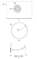
次に、S203の詳細について説明する。ここで、点光源ぼかし処理のモデルとする現象について説明する。図4はデジタルカメラ等において実際にレンズを通して撮影した場合の点光源の玉ボケの発生を説明するための図である。図4ではデジタルカメラ、デジタルカメラに対する入光、レンズ等は説明のため簡略化して示してある。 Next, details of S203 will be described. Here, a phenomenon used as a model of the point light source blurring process will be described. FIG. 4 is a diagram for explaining the occurrence of blurring of a point light source when an image is actually taken through a lens in a digital camera or the like. In FIG. 4, the digital camera, light incident on the digital camera, lenses, and the like are shown in a simplified manner for explanation.
図4において、光405が左から右に向けて入るものとし、光軸401が中心部に存在する。デジタルカメラに入った通常の光405は、レンズ403を介して結像面404(イメージセンサ)へ到達する。なお、レンズ403は球面レンズを想定しているが、簡略化のためここでは平面で図示している。ここでは点光源に対応する光(背景から入ってくる光)に対する説明であるため、結像面404ではピントが合っていない(焦点が結像面404より前)状態となっている(被写体にはピントが合っている状態である)。
In FIG. 4, it is assumed that
このとき、デジタルカメラに入ってきた光のうち絞り402で遮られた光406は本来ならレンズ403に入ってこないが、光の特性である回折現象により絞り402の裏側にある程度回り込み、レンズ403を通り結像面404に届く。なお、光の回折とは、光が障害物にぶつかった場合に、光の波動性のため光が障害物の背後に回り込んで伝わって行く現象のことである。このように光の回折により、結像面404で作られる画像は、絞り402の内側を通った光405に加え、絞り402で遮られた光406の影響を受ける。またこの光はピントが合っていないため、一点に集まる光が拡散されて結像面404に入るので遮られた光406の影響が大きくなる。
At this time, the light 406 blocked by the aperture 402 out of the light that has entered the digital camera does not normally enter the lens 403, but circulates to the back side of the aperture 402 to some extent due to the diffraction phenomenon that is a characteristic of the light. And reaches the
この現象はカメラレンズに入ってくる光が強いほど遮られた光406も強くなり、それが顕著に表れる。また遮られた光406は回折により光軸401に対して斜めの光としてレンズ403に入る。そのため遮られた光406の焦点は光軸から離れる方向にずれる。そのため結像面404に入るときは、通常の光405と合成されて結像される。そのため、点光源の玉ボケ内においては中心部と比べ中心部より外側(周辺部)の方が輝度が高くなる。
This phenomenon becomes more noticeable as the light entering the camera lens is stronger and the light 406 is blocked. The blocked
また、点光源(背景)がより遠くなったり被写界深度がより浅くなったりする場合、結像面に入ってくる通常の光405の焦点は結像面404からより離れることになる。そのため、結像面404に入ってくる光によってできるボケの大きさは大きくなり、それに連れて輝度は下がっていく。また、遮られた光406と通常の光405とは異なる角度で結像面404に入る。そのため、焦点と結像面404とが離れていると、所定の距離までは遮られた光406は通常の光405と合成され、かつ所定の距離に近づくにつれ徐々に通常の光405の縁に集まるように変化する。それ以上の距離になると遮られた光406は通常の光605の外側で結像面に入るため、無視できる光の強さになる。
In addition, when the point light source (background) becomes farther or the depth of field becomes shallower, the focus of the
このようにカメラレンズに入るある一定以上の明るさを持つ背景からの光は、回折が起こり中心部の輝度より周辺部の輝度の方が高いものとなる。 As described above, the light from the background having a certain level of brightness entering the camera lens is diffracted, and the luminance at the peripheral portion is higher than the luminance at the central portion.
以上のような実際のレンズを通した撮影において点光源の玉ボケに対して発生する現象をモデルとし、点光源ぼかし処理においてはこの現象に近づくように画像データの処理を行う。 The phenomenon that occurs due to the blur of the point light source in shooting through the actual lens as described above is used as a model, and in the point light source blurring process, image data is processed so as to approach this phenomenon.
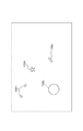
図5(a)において、処理対象の画像領域501内で、S201で検出された点光源領域が502であった場合、その周囲に点光源領域502を囲むように拡大された領域である加算領域503を設定する。そして、加算領域503の外周より内側(点光源領域502も含む)に次のようにぼかし処理を施す。
In FIG. 5A, when the point light source region detected in S201 is 502 in the
まず、点光源領域502の各画素の平均輝度値または中心点に相当する画素の輝度値を基にして基準となる加算輝度値を算出する。そして点光源領域502の大きさや平均輝度値、UI105からの指定等に基づくぼかし強度などから点光源領域502より広い加算領域503が決定され、これを加算領域として設定する。
First, a reference added luminance value is calculated based on the average luminance value of each pixel in the point
この加算領域503の内側にある画素に対して、予め決められた加算輝度値に中心点からの距離に応じて決められた加算係数を用いて得た輝度値を加算していく。加算輝度値をYadd、加算係数をk、注目画素輝度をYorg、出力画素輝度をYoutとすると、下記の式で出力画素輝度を算出できる。
Yout=(1−k)×Yorg+k×Yadd (式1)
このとき、加算係数kは、図4で説明したように玉ボケとなる部分の外周の輝度値が高くなるように設定する。
The luminance value obtained by using the addition coefficient determined according to the distance from the center point is added to the predetermined added luminance value for the pixels inside the
Yout = (1−k) × Yorg + k × Yadd (Formula 1)
At this time, the addition coefficient k is set so that the luminance value of the outer periphery of the portion that is blurred as described with reference to FIG.
なお、出力輝度値の範囲を特定の範囲に限定すべき場合は、出力輝度値に特定の範囲を指定したクリップ処理を行って、適切な範囲となるように演算するようにしてもよい。 When the range of the output luminance value is to be limited to a specific range, clip processing with a specific range specified for the output luminance value may be performed to perform calculation so as to be an appropriate range.
また、加算輝度値Yaddは加算領域503の大きさに基づいて変化させてもよい。この場合、所定の基準面積を決め、基準面積に対して加算領域503の面積が大きいときは加算輝度値Yaddが小さくなるようにし、小さいときは大きくなるようにする。
Further, the addition luminance value Yadd may be changed based on the size of the
なお、以上では各画素の輝度値について演算するようにしたが、上記の処理を各画素の画素値について行ってもよい。こうすることで輝度だけではなく、画素の色に基づいても点光源のぼかし処理が行える。以下では、例として赤(R)緑(G)青(B)の三原色で構成されている各色成分の画素について演算する(画素値を変更する)場合について説明する。 In the above description, the luminance value of each pixel is calculated. However, the above processing may be performed on the pixel value of each pixel. In this way, the point light source can be blurred not only based on the luminance but also based on the pixel color. Hereinafter, as an example, a case will be described in which calculation is performed on pixels of each color component configured by the three primary colors of red (R), green (G), and blue (B) (the pixel value is changed).
ここでは上記と同様に点光源領域502の平均画素値や中心点画素値などを基にして基準となる加算画素値を算出する。加算領域503の内側の画素に対して加算係数を用いて加算していく。加算画素値をRadd、Gadd、Badd、加算係数をk、注目画素値をRorg、Gorg、Borg、出力画素値をRout、Gout、Bout、とすると、下記の式で出力画素値を算出できる。
Rout=(1−k)×Rorg+k×Radd (式2)
Gout=(1−k)×Gorg+k×Gadd (式3)
Bout=(1−k)×Borg+k×Badd (式4)
Here, in the same manner as described above, the reference added pixel value is calculated based on the average pixel value and the center point pixel value of the point
Rout = (1−k) × Rorg + k × Radd (Formula 2)
Gout = (1−k) × Gorg + k × Gadd (Formula 3)
Bout = (1−k) × Borg + k × Badd (Formula 4)
出力輝度値の範囲を特定の範囲に限定すべき場合は、出力輝度値に特定の範囲を指定したクリップ処理を行って、適切な範囲となるように演算する。加算画素値Radd、Gadd、Baddは加算領域503の大きさに基づいて変化させてもよい。この場合、所定の基準面積を決め、基準面積に対して加算領域503が広いときは加算画素値Radd、Gadd、Baddが小さくなり、狭いときは大きくなるようにする。
When the range of the output luminance value is to be limited to a specific range, clip processing is performed in which the specific range is specified for the output luminance value, and calculation is performed so as to be an appropriate range. The addition pixel values Radd, Gadd, and Badd may be changed based on the size of the
次に以上の演算で用いた加算係数kの決定方法の例について図5(b)、(c)を用いて説明する。ここでは下記のような2次関数を用いて加算係数を決めている。加算係数をk、点光源の中心504からの距離をr、中心504から加算領域503の外周までの半径をR、aとbは任意の定数とする。ただしkは0.0から1.0の間とする。
1.0=a×R2+b (式5)
1.0≧b≧0.0 (式6)
a≧0.0 (式7)
これらを前提条件として加算係数kは下記の式で算出できる
k=a×r2+b (式8)
Next, an example of a method for determining the addition coefficient k used in the above calculation will be described with reference to FIGS. Here, the addition coefficient is determined using the following quadratic function. The addition coefficient is k, the distance from the
1.0 = a × R 2 + b (Formula 5)
1.0 ≧ b ≧ 0.0 (Formula 6)
a ≧ 0.0 (Formula 7)
With these as preconditions, the addition coefficient k can be calculated by the following equation: k = a × r 2 + b (Equation 8)
なお、加算領域503の面積に基づいて加算係数kを変化させてもよい。この場合、加算領域503が広いときの中心部と周辺部の輝度差より、狭いときの輝度差を大きくする。その場合は、所定の基準面積Sbaseを決め、その基準面積でのbをbbaseとすると、上記前提条件に下記の式を加えることで実現できる。
b=bbase×S÷Sbase (式9)
このときbが1.0より大きくなった場合はbが1.0になるようクリップ処理してもよい。
Note that the addition coefficient k may be changed based on the area of the
b = bbase × S ÷ Sbase (Formula 9)
At this time, when b becomes larger than 1.0, the clip processing may be performed so that b becomes 1.0.
また、加算係数の決定方法は上記のような2次関数以外に基づき求めてもよい。加算係数kの決定方法は加算領域503の中心点504より周辺付近の係数の方が高くなっており、また線形に増加するのではなく図5(c)に示すように下に凸な形で増加しているという特徴があれば他の方法でもよい。例えば、表示や印刷のためのガンマ補正の際に用いられるガンマを使って決定してもよいし、予め計算結果を用意したテーブルを作成して決定してもよい。この加算係数は上述した光の回折を考慮した特性に基づいた値となっている。ここでは加算領域を円形として記述したが、多角形など他の形状でもよい。この場合、上記での加算領域の半径Rは、加算領域の中心点から最も遠い加算領域内の位置になる。また円の中心点を加算係数の開始点としたが、加算領域の形や輝度分布などから開始点を変えてもよい。
The addition coefficient determination method may be obtained based on a function other than the quadratic function as described above. In the determination method of the addition coefficient k, the coefficient near the periphery is higher than the
また、点光源位置と加算領域の大きさによっては、複数の点光源に対する加算領域が重なり合う場合がある。そのとき上記のように出力画素値を算出し、出力画素値同士を比較して値の高い方を出力画素値として出力してもよい。または出力画素値の平均値を出力画素値としてもよい。 Further, depending on the position of the point light source and the size of the addition area, the addition areas for a plurality of point light sources may overlap. At that time, the output pixel value may be calculated as described above, the output pixel values may be compared, and the higher value may be output as the output pixel value. Alternatively, an average value of output pixel values may be used as the output pixel value.
以上のようにして、画像データの輝度値を変更することによって、レンズを通して撮影した場合の点光源ぼかし処理をより忠実に再現することができる。 As described above, by changing the luminance value of the image data, it is possible to more faithfully reproduce the point light source blurring process when photographing through the lens.
なお、以上の処理においてS201では、点光源と判断された画素が逐次検出される。このとき、S203でぼかす対象にする点光源領域は、周囲の画素が点光源であった場合は、ひとまとまりとして点光源領域として扱ってもよいし、検出された点光源の一画素ずつを別々の点光源領域として扱ってもよい。 In the above processing, in S201, pixels determined as point light sources are sequentially detected. At this time, the point light source region to be blurred in S203 may be treated as a point light source region as a whole when the surrounding pixels are point light sources, or each pixel of the detected point light source is separately separated. May be treated as a point light source region.
また、以上のような処理(背景ぼかし)を行う際、主要な被写体にはピントが合った状態とする必要がある。即ち、特定のオブジェクト(主要な被写体)にはぼかしがかからないようにする必要がある。この場合、図6に示すように以下の手順で処理することでこれを容易にかつ精度良く実現することができる。 Further, when performing the above processing (background blurring), it is necessary to keep the main subject in focus. In other words, it is necessary to prevent a specific object (main subject) from being blurred. In this case, as shown in FIG. 6, this can be easily and accurately realized by processing according to the following procedure.
S601では、入力された画像データから被写体(ピントを合わせるべきオブジェクト)の抽出を行い、主要被写体と背景を分離する。ここで分離する方法は、ディスプレイ104で対象となる画像を表示させ、UI105を用いてユーザに領域を指定させるものとしてもよいし、自動的に被写体を特定して分離させるようにしてもよい。自動で分離させる場合、画像データに付加されている被写界深度などの撮影条件の情報などを用いて被写体を特定するようにしてもよい。なお、ユーザに領域を指定させる場合、図6のフローが開始される前の段階でユーザに指定させる。また、領域の指定に際してはユーザにラフに指定させ、指定された領域の近傍のエッジをCPU100が検出するなどして、CPU100が最終的な領域を決定する半自動方式としてもよい。
In step S601, a subject (an object to be focused) is extracted from the input image data, and the main subject and the background are separated. As a separation method, the target image may be displayed on the
主要被写体と背景が分離できたらS602に進み、背景と主要被写体とを区別するための背景マスクD601を作成する。ここで、背景マスクD601とは、処理対象の画像データからS601で抽出した主要被写体を除き(画像なしに置き換え)、背景のみとしたものである。そして、この背景マスクD601に対してS603〜605における処理を施す。S603〜605は前述のS201〜203と同様の処理を行う。このとき、背景マスクD601のうち背景に対応する領域の画素だけでS603以降の処理を行ってもよいし、全画素に対してS603の処理を行ってもよい。また、検出された点光源の位置と背景マスクD601とを比較して背景に対応する領域に対しS604以降の処理を行ってもよい。また、S605において、例えば加算領域503が主要被写体領域に重なっている場合は、重なっていないところだけ加算処理を行うようにしてもよい。また、主要被写体領域の画素は加算画素値を算出する対象から除くようにしてもよい。
If the main subject and the background can be separated, the process proceeds to S602, and a background mask D601 for distinguishing the background from the main subject is created. Here, the background mask D601 is a background only except for the main subject extracted in S601 from the image data to be processed (replaced with no image). Then, the processing in S603 to 605 is performed on the background mask D601. S603 to 605 perform the same processing as S201 to 203 described above. At this time, the processing after S603 may be performed only for the pixels in the region corresponding to the background in the background mask D601, or the processing of S603 may be performed for all the pixels. Further, the position of the detected point light source and the background mask D601 may be compared, and the processing corresponding to the background may be performed on and after S604. In S605, for example, when the
そして、S605の処理が行われた後、抽出された主要被写体を戻すことによって、主要被写体にはピントが合った状態で、背景部分にはぼかし処理が施された画像を得ることができる。 Then, after the processing of S605 is performed, the extracted main subject is returned to obtain an image in which the main subject is in focus and the background portion is blurred.
以上のように本実施例では、光源領域をぼかすときに中心付近より周辺付近の方が輝度が高くなるように(明るい画像となるように)ぼかすことで、デジタル画像加工処理において実際のレンズで撮影したかのような風合いを再現することが可能となる。 As described above, in this embodiment, when blurring the light source region, the brightness near the periphery is higher than that near the center (so that a bright image is obtained). It is possible to reproduce the texture as if it were taken.
<実施例2>
デジタルカメラ等によってレンズを用いて撮影した場合、画角の中心にピントを合わせ、上述のように背景をぼかすと、レンズの光学特性により画角の中心から離れるに従い、玉ボケの形状は扁平していく。実施例2では、実施例1における処理を行う際のぼかし領域の形状をレンズの光学特性を考慮し、その位置に応じた形状に変化させる場合の処理について述べる。
<Example 2>
When shooting using a lens with a digital camera, etc., focusing on the center of the field of view and blurring the background as described above, the shape of the bokeh becomes flatter as the distance from the center of the field of view increases due to the optical characteristics of the lens. To go. In the second embodiment, a process for changing the shape of the blur region when performing the process in the first embodiment to a shape corresponding to the position in consideration of the optical characteristics of the lens will be described.
図7(a)は、処理対象の画像データの全域を示している。図7(a)では説明のために画像データが表す画像の中心に原点701、原点を通り垂直方向にy軸、水平方向にx軸をとっている。画像データが表す画像は、高さ(height)と幅(width)で表され、処理対象の画像データは、height×width個の画素で構成されているものとする。各画素は、
p(x,y) {x|−width≦x<width,y|−height/2≦y<height/2} (式10)
で表される。本実施例では処理対象の画像データの画像はheight<widthである横長の長方形となっているものを例に説明する。
FIG. 7A shows the entire area of the image data to be processed. In FIG. 7A, for the purpose of explanation, the origin 701 is taken at the center of the image represented by the image data, the y axis is taken in the vertical direction through the origin, and the x axis is taken in the horizontal direction. The image represented by the image data is represented by a height and a width, and the processing target image data is composed of height × width pixels. Each pixel is
p (x, y) {x | −width ≦ x <width, y | −height / 2 ≦ y <height / 2} (Formula 10)
It is represented by In the present embodiment, an example in which the image of the image data to be processed is a horizontally long rectangle with height <width will be described.
また、図7(a)中の黒丸の点は、S201によって検出された点光源の画素を示す。図7(a)では、画像の中心にあるP0(0,0)701と、P1(x,y)702を含む複数点が点光源として検出された状態を示している。 Moreover, the black dot in FIG. 7A indicates the pixel of the point light source detected in S201. FIG. 7A shows a state where a plurality of points including P0 (0, 0) 701 and P1 (x, y) 702 at the center of the image are detected as point light sources.
そして、検出された点光源の位置が画像全体に対して原点からどれだけ離れているかによって、形状の異なる複数のボケマスクを使い分ける。即ち、原点に近いものは真円に近い形とし、原点から離れるに従って扁平させた楕円形状のボケマスクとする。ここで、ボケマスクとは図5で示した加算領域503に対応し、当該マスク内でぼかし処理を施し、点光源のボケ画像を得るための領域である。
A plurality of blur masks having different shapes are used depending on how far the detected position of the point light source is from the origin with respect to the entire image. That is, a shape close to the origin is a shape close to a perfect circle, and an elliptical blur mask flattened away from the origin. Here, the blur mask corresponds to the
P0(0,0)701のぼかし補正では、図7(b)に示すボケマスク領域703を使用する。P0(0,0)701を中心に、大きさ2R0の補正領域が設定される。P0(0,0)701から半径R0の範囲内にある画素が補正対象となる。本実施例では、画像の中心位置のマスク領域703の形状は円形とする。R0は初期値として適当な値を指定することが可能であり、大きいほどボケの度合いが大きくなる。本実施例では、R0は、画像のwidthの5%の固定値とする。R0は、ユーザの指定によって可変とするようにしてもよく、その際には、補正効果をユーザが選択できるという効果が出てくる。
In the blur correction of P0 (0, 0) 701, a
原点から予め決められた距離離れた範囲にあるP1(x,y)702のぼかし補正は、図7(c)に示すボケマスク領域704を使用する。図7(c)で示されるボケマスク領域は、P1(x,y)702の座標に応じて変化する。その変化の制御を以下に説明する。ボケマスク領域704は、長辺R0、短辺R(x,y)、さらに角度θ°だけ回転した楕円形とする。ここで、R(x,y)との定義は以下の様にする。
R(x,y)=R0×(width−(l/2))/width(式11)
ただし、l=(x2+y2)1/2 (式12)
θ:中心点P0(0,0)701とP1(x,y)702とを結ぶ直線と、x軸とのなす角度[°]
The blur correction of P1 (x, y) 702 that is within a predetermined distance from the origin uses a
R (x, y) = R0 × (width− (l / 2)) / width (Formula 11)
However, l = (x 2 + y 2 ) 1/2 (Formula 12)
θ: Angle [°] formed by a straight line connecting the center point P0 (0,0) 701 and P1 (x, y) 702 and the x axis
このようにして定義されるボケマスク領域の形状を図7(d)に示す。加算領域を以上のように中心から離れるに従って扁平させる点以外は実施例1に示した処理を施す。図7(d)に示されるように、中心に近づくほど円形に近いボケ効果が得られ、端部ほどより扁平した形状のボケ効果が得られるようになっている。即ち、点光源領域の画角内における位置に応じてぼかし処理を施す範囲を異ならせることによってレンズを通して撮影した画像の再現性が向上する。さらに扁平する方向が原点を中心に回転しており、よりレンズによる光学的特性に従った点光源のボケの状態を再現できるようになっている。 The shape of the blur mask area defined in this way is shown in FIG. The processing shown in the first embodiment is performed except that the addition region is flattened as the distance from the center increases as described above. As shown in FIG. 7D, a blur effect close to a circle is obtained as the distance from the center is approached, and a blur effect having a flatter shape is obtained at the end. That is, the reproducibility of an image photographed through a lens is improved by varying the blurring range according to the position of the point light source region within the angle of view. Further, the flattening direction rotates around the origin, and the blurring state of the point light source according to the optical characteristics of the lens can be reproduced.
<実施例3>
実施例2では、点光源の座標によって、ボケマスク領域の扁平率と回転を制御する例について述べた。しかし、デジタルカメラ等によってレンズを通して実際に撮影された画像では、画像の端部に行くに従って、ボケ領域が大きくなる。これはレンズの中心から離れるに従ってボケの度合いが大きくなるためである。そこで、本実施例では実施例2のボケマスク領域の形状の制御に加え、端部に行くほどボケマスク領域のサイズを大きくする制御を加えることで、実施例2よりも、より実際にレンズを用いて撮影した際のボケ画像に近づく補正効果を得るものである。
<Example 3>
In the second embodiment, the example in which the flatness and rotation of the blur mask area are controlled by the coordinates of the point light source has been described. However, in an image actually taken through a lens by a digital camera or the like, the blur area increases as it goes to the edge of the image. This is because the degree of blur increases as the distance from the center of the lens increases. Therefore, in this embodiment, in addition to the control of the shape of the blur mask area of the second embodiment, the control is performed to increase the size of the blur mask area toward the end, so that the lens is actually used more than in the second embodiment. A correction effect that approximates a blurred image at the time of shooting is obtained.
以下では、実施例2との差分のみ説明する。その他の部分は実施例1、2と同じ処理が実行されるものとする。 Only the differences from the second embodiment will be described below. In other parts, the same processing as in the first and second embodiments is executed.
実施例2では、図7(c)において、楕円の短辺R(x,y)が座標p(x,y)の関数となって変化し、長辺R0は固定であった。実施例3では、楕円の長編をR’(x,y)として、座標p(x,y)の関数として求めることで、画像の端部ではボケマスク領域が拡大されるように制御する。このため、R’(x,y)を以下のように定義する。
R’(x,y)=R0×cosh(Z) (式13)
ただし、Z=l/(width)×π/2,l=(x2+y2)1/2 (式14)
これにより、R’は、図8(a)に示すように下に凸の単調増加の曲線となり、画像の端部にいくほど値が大きくなる。
In Example 2, in FIG. 7C, the short side R (x, y) of the ellipse changed as a function of the coordinate p (x, y), and the long side R0 was fixed. In the third embodiment, the oblong feature is determined as a function of the coordinates p (x, y) as R ′ (x, y), and the blur mask region is controlled to be enlarged at the edge of the image. For this reason, R ′ (x, y) is defined as follows.
R ′ (x, y) = R0 × cosh (Z) (Formula 13)
However, Z = l / (width) × π / 2, l = (x 2 + y 2 ) 1/2 (Formula 14)
As a result, R ′ becomes a monotonically increasing curve convex downward as shown in FIG. 8A, and the value increases as it goes to the edge of the image.
このようにして定義されるボケマスク領域の形状を図8(b)に示す。図8(b)に示されるように、中心では円形のボケ効果が得られ、端部ほど扁平した形状になるとともに、実施例2と同様に扁平する方向が原点を中心に回転する形状としながらも、端部ほどボケマスク領域が大きくなっている。これにより、実施例2よりさらにレンズの光学的な特性を考慮したボケの状態を再現できるようになる。 The shape of the blur mask area defined in this way is shown in FIG. As shown in FIG. 8B, a circular blur effect is obtained at the center, the end becomes flat, and the flat direction rotates around the origin as in the second embodiment. However, the blur mask region becomes larger toward the end. As a result, it is possible to reproduce the blurring state in consideration of the optical characteristics of the lens more than in the second embodiment.
なお、R’を制御する関数に双曲線関数のcosh()を使用したが、特にこの関数に限定するものではない。端部に行くにしたがって増加する特性を持った関数であればよい。 Note that although the hyperbolic function cosh () is used as a function for controlling R ′, the function is not particularly limited to this function. Any function may be used as long as the function increases toward the end.
また、実施例3では、実施例2のボケマスク領域の形状の制御にサイズを変化させる制御を追加したが、形状を変化させずにサイズ(面積)を変化させる制御のみでボケマスク領域を決定してもよい。 In the third embodiment, the control for changing the size is added to the control of the shape of the blur mask area in the second embodiment. However, the blur mask area is determined only by the control for changing the size (area) without changing the shape. Also good.
<実施例4>
以上の実施例において、点光源の検出(S201、S603)を、注目画素の輝度値が周辺画素の輝度値よりも所定閾値よりも高いものを抽出することによって行うことを示した。即ち、周辺に比べて周辺に比べて突出して明るい画素(画素群)を点光源として検出することを示した。しかしながら、デジタルカメラ等で実際に撮影される画像は種々の撮影状態が存在し得て、点光源はその撮影状態に応じてその特徴が異なることがある。本実施例では、点光源の検出の精度を上げるための方法について述べる。
<Example 4>
In the above embodiment, it has been shown that the point light source detection (S201, S603) is performed by extracting a pixel whose luminance value is higher than a predetermined threshold value than the luminance value of the surrounding pixels. That is, it is shown that a bright pixel (pixel group) that protrudes compared to the periphery and brighter than the periphery is detected as a point light source. However, an image actually photographed with a digital camera or the like can have various photographing states, and a point light source may have different characteristics depending on the photographing state. In this embodiment, a method for improving the accuracy of detection of a point light source will be described.
画像の撮影状態は、様々な条件が考えられる。例えば、夜景撮影の場合と晴天の昼光下における撮影の場合とでは、点光源の明るさに違いが出てくることがある。また、曇天の時に露出不足の状態で撮影した画像などは、全体的に低い輝度値となる。 Various conditions are conceivable for the image capturing state. For example, there may be a difference in the brightness of the point light source between night scene shooting and shooting in sunny daylight. Also, an image taken underexposure when it is cloudy has a low luminance value as a whole.
本実施例ではこのような状況を考慮し、処理対象の画像の特徴を解析し、その結果により当該画像の撮影状態を推定し、その結果に基づき点光源の検出の際のパラメータを変更したり、さらに点光源候補の領域の形状や大きさも考慮するものである。なお、画像の特徴の解析結果から撮影状態を推定するものであり、処理対象の画像は実際にその状態で撮影されたものとは限らないし、そもそも撮影によって得られた画像とも限らない。 In this embodiment, in consideration of such a situation, the characteristics of the image to be processed are analyzed, the shooting state of the image is estimated based on the result, and the parameters for detecting the point light source are changed based on the result. Furthermore, the shape and size of the point light source candidate region are also taken into consideration. Note that the shooting state is estimated from the analysis result of the feature of the image, and the image to be processed is not necessarily actually shot in that state, and is not necessarily an image obtained by shooting in the first place.
図9は、本実施例における点光源検出処理(S201、S603)の流れを示すフローチャートである。 FIG. 9 is a flowchart showing the flow of point light source detection processing (S201, S603) in the present embodiment.
S901では、処理対象の入力画像データIin(x,y)(各画素RGB成分で構成されたカラー画像)を所定サイズにリサイズし、リサイズ後の画像データIre(x,y)を得る。ここでx,yは画像上での座標位置を示す。入力される画像データのサイズ(画像データが表す画像の縦横サイズの組合せ)が複数存在する場合、後続の処理において点光源の大きさを判断する時などに、元画像のサイズを考慮した判定をする必要がある。従ってここでは、いずれのサイズの画像データが入力されても予め決められたサイズにリサイズすることで、以降の処理における制御パラメータを統一化できるようにする。リサイズに際しては画素の補間、または画素の間引きを行う。リサイズ後のサイズについては特に限定するものではないが、例えば、1600×1200画素など画素数を基準に統一されたサイズにリサイズする。ただし、ここでリサイズを行わずに、入力された画像データをそのまま用いて後段の処理に移るようにしてもよいし、リサイズさせる場合はリサイズ後のサイズを常に同一とする必要もない。また、リサイズを縮小する処理(間引き)に限定し、処理対象の画像データの量を減らし、負荷軽減を図るようにしてもよい。以下では処理対象の画像データを所定のサイズにリサイズを行った場合について述べる。処理対象の画像データは1画素につき多値の画像データである。 In S901, the input image data Iin (x, y) to be processed (color image composed of RGB components) is resized to a predetermined size, and resized image data Ire (x, y) is obtained. Here, x and y indicate coordinate positions on the image. When there are multiple sizes of input image data (a combination of the vertical and horizontal sizes of the image represented by the image data), a determination that considers the size of the original image is made when determining the size of the point light source in subsequent processing. There is a need to. Therefore, in this case, the control parameters in the subsequent processes can be unified by resizing to a predetermined size regardless of which size of image data is input. In resizing, pixel interpolation or pixel thinning is performed. The size after resizing is not particularly limited. For example, the size is resized to a standard size based on the number of pixels such as 1600 × 1200 pixels. However, the resizing is not performed here, and the input image data may be used as it is to move to the subsequent process. When resizing is performed, it is not always necessary to have the same size after resizing. Further, it may be limited to the process of reducing the resizing (thinning), and the amount of image data to be processed may be reduced to reduce the load. Hereinafter, a case where image data to be processed is resized to a predetermined size will be described. The image data to be processed is multivalued image data per pixel.
S902では、リサイズされた処理対象の画像データに対して適応的2値化処理を行う。図10はS902における処理の詳細を示すフローチャートである。 In S902, adaptive binarization processing is performed on the resized image data to be processed. FIG. 10 is a flowchart showing details of the processing in S902.
S1001では、入力されたカラー画像データに対して、画素単位で輝度・色差変換を行う。輝度・色差成分については種々のものを採用可能であるが、ここでは、YCbCr成分に変換するものとし、変換後の画像をIrey(x,y)とする。ここでの変換は公知の変換方式を採用可能である。 In step S1001, luminance / color difference conversion is performed on the input color image data in units of pixels. Various types of luminance and color difference components can be employed. Here, the luminance and color difference components are converted into YCbCr components, and the converted image is assumed to be Irey (x, y). A known conversion method can be adopted for the conversion here.
S1002では、Irey(x,y)におけるY(輝度)成分のヒストグラムを算出する。図11は、S1002で算出したヒストグラムの例であり、横軸は輝度値Y、縦軸は度数(画素数)を示している。 In S1002, a histogram of the Y (luminance) component in Irey (x, y) is calculated. FIG. 11 is an example of the histogram calculated in S1002, in which the horizontal axis indicates the luminance value Y and the vertical axis indicates the frequency (number of pixels).
次にS1003において、ハイライトポイントの算出を行う。ハイライトポイントとは、ヒストグラムの累積度数割合が予め決められた割合(例えば97.0%)となる高輝度ポイントであり、図11においてHLYで示した箇所である。また処理対象の画像データにおける最大輝度値は図中MaxYで示した箇所である。ここでハイライトポイントを求めるのは、度数分布における上位および下位の数パーセントの領域はノイズである可能性が高いという統計学上の考えを適用したものである。そのため、ここではMaxYではなく、HLYを基準として後述の点光源閾値を決定する。これにより画像中、ノイズの可能性のある最高輝度の画素の影響を排除して適切な点光源抽出を行う。 In step S1003, a highlight point is calculated. A highlight point is a high-intensity point at which the cumulative frequency ratio of the histogram is a predetermined ratio (for example, 97.0%), and is a location indicated by HLY in FIG. Further, the maximum luminance value in the image data to be processed is a portion indicated by MaxY in the drawing. Here, the highlight point is obtained by applying a statistical idea that the upper and lower several percent regions in the frequency distribution are likely to be noise. For this reason, the point light source threshold described later is determined based on HLY instead of MaxY. As a result, appropriate point light source extraction is performed by eliminating the influence of the pixel having the highest luminance that may cause noise in the image.
そしてS1004において、Irey(x,y)上の画素単位で順次2値化処理を行う。図12は、S1004における2値化処理の詳細を示すフローチャートである。まずS1201において、重みWを決定する。後続の2値化処理において、2値化を行う際に0とするか1とするかを決めるための輝度閾値ThYは、重みWとHLYとを用いて、以下のように決定する。
ThY=HLY×W (式15)
In step S1004, binarization processing is sequentially performed in units of pixels on Irey (x, y). FIG. 12 is a flowchart showing details of the binarization processing in S1004. First, in S1201, the weight W is determined. In the subsequent binarization process, the luminance threshold value ThY for determining whether the binarization is set to 0 or 1 is determined using the weight W and HLY as follows.
ThY = HLY × W (Formula 15)
S1201で決定される重みは、本実施例においては予め決められた所定値とし、例えば0.9などの値とする。重みWが決定されたら、S1202〜1203において、Irey(x,y)の各画素に対して以下の条件に従って2値化処理を行い、2値化済み画像データIreb(x,y)を生成する。
Irey(x,y)のY成分≧ThYのときIreb(x,y)=1,Irey(x,y)のY成分<ThYのときIreb(x,y)=0 (式16)
The weight determined in S1201 is a predetermined value determined in advance in the present embodiment, for example, 0.9. When the weight W is determined, in S1202 to 1203, binarization processing is performed on each pixel of Irey (x, y) according to the following conditions to generate binarized image data Ireb (x, y). .
When Y component of Irey (x, y) ≧ ThY, Ireb (x, y) = 1, Y component of Irey (x, y) <ThY when Ireb (x, y) = 0 (Expression 16)
このようにして生成された2値化済み画像データIreb(x,y)を、図13に示す。図13において、1301〜1304は輝度が高い画素群である領域(ハイライト領域)として抽出された領域群である。ここでは図に示すように様々な大きさや形状の領域が含まれているものとする。
The binarized image data Ireb (x, y) generated in this way is shown in FIG. In FIG. 13,
処理は図9に戻り、S903において、2値化済み画像データIreb(x,y)上に存在する領域(1301〜1304)のクラスタリングを行う。領域のクラスタリング手法については特に限定するものではなく、ラベリング処理等の公知の方法を用いればよい。ここでは、演算量が少なく、かつ領域の大きさや形状把握が容易に行える境界線追跡法を用いて説明する。 The processing returns to FIG. 9, and in S903, the regions (1301 to 1304) existing on the binarized image data Ireb (x, y) are clustered. The region clustering method is not particularly limited, and a known method such as a labeling process may be used. Here, the description will be made using a boundary line tracking method that requires a small amount of calculation and can easily grasp the size and shape of a region.
図14は境界線追跡法によるクラスタリングを説明するための図である。図14(a)において、1401は2値化済み画像データIreb(x,y)の一部を示している。本実施例の境界線追跡法では、まず2値化済み画像データを左上から右下に向かって順次走査していき、Ireb(x,y)の値が1である画素で一時停止する。その後、領域の境界に存在する画素を反時計回り(時計回りでもよい)に順次探索してゆき、一時停止した画像まで戻ったら、1つの領域の探索が終了する。この1つの領域の境界を追跡する間に、領域の最大最小座標位置(Xmin,Xmax,Ymin,Ymax)や周辺長Larrを算出する。最大最小座標位置が得られれば、領域の中心位置(Cx,Cy)は以下のように求めることができる。
Cx=(Xmax+Xmin)/2,Cy=(Ymax+Ymin)/2 (式17)
FIG. 14 is a diagram for explaining clustering by the boundary line tracking method. In FIG. 14A,
Cx = (Xmax + Xmin) / 2, Cy = (Ymax + Ymin) / 2 (Formula 17)
一つの領域についての探索が終了すると、CPU100は探索の結果を示す情報をRAM102に記憶し、次の領域の探索を行うために、再び水平方向に走査を開始する。図14(b)は、本処理の結果得られた情報が、領域探索順に割り当てられたIDと対応付けられて記憶されている様子を示している。ここでは記号で示しているが実際には数値によって座標や長さが記憶される。
When the search for one area is completed, the
そしてS904では、図14(b)に示す領域IDと領域座標情報などのクラスタリング情報を用いて点光源の抽出(特定)を行う。図15はS904において点光源の抽出(点光源の位置を特定)する処理の流れを示すフローチャートである。 In step S904, point light sources are extracted (specified) using clustering information such as the region ID and region coordinate information shown in FIG. FIG. 15 is a flowchart showing the flow of processing for extracting a point light source (specifying the position of the point light source) in S904.
まず、ID=0の領域に対してS1501において、当該領域のサイズが適切か判定する。この判定は以下の式に従って行う。
(XmaxID−XminID)≦ThSizeかつ(YmaxID−YminID)≦ThSize (式18)
上式において、ThSizeは点光源の大きさの上限を示す所定の閾値であり、予め決められているものとする。
First, in step S1501, it is determined whether the area size is appropriate for the area with ID = 0. This determination is performed according to the following equation.
(XmaxID−XminID) ≦ ThSize and (YmaxID−YminID) ≦ ThSize (Formula 18)
In the above equation, ThSize is a predetermined threshold value indicating the upper limit of the size of the point light source, and is predetermined.
上式を満たすと判定された場合、S1502に進み、当該領域の周辺長の長さが適切か(点光源となり得る長さであるか)判定する。この判定は、以下の式に従って。
abs(LarrID−LrectID×K)≦ThArrL (式19)
上記において、abs( )は絶対値を求める関数であり、LrectIDおよびKは以下の式によって求める。
LrectID=((XmaxID−XminID)+(YmaxID−YminID))×2 (式20)
K=π/4=0.785 (式21)
If it is determined that the above expression is satisfied, the process proceeds to S1502, and it is determined whether the length of the peripheral length of the area is appropriate (is a length that can be a point light source). This determination is according to the following formula.
abs (LarrID−RectID × K) ≦ ThArrL (Formula 19)
In the above, abs () is a function for obtaining an absolute value, and RectID and K are obtained by the following equations.
RectID = ((XmaxID−XminID) + (YmaxID−YminID)) × 2 (Formula 20)
K = π / 4 = 0.785 (Formula 21)
上式において、LrectIDは注目領域を取り囲む矩形の周辺長であって、このLrectIDに上記Kを乗じることにより、矩形内に隣接する円、または楕円の周辺長を近似的に求めることができる。この周辺長と、実際に境界線追跡処理において計測した周辺長LarrIDとの絶対差が、所定の閾値ThArrLより大きい場合、点光源候補の領域の形状が、円または楕円ではなく、もっと複雑な形状をしている可能性が高い。従って当該領域は点光源リストから除外する。 In the above formula, RectID is the peripheral length of a rectangle surrounding the region of interest, and by multiplying the RectID by K, the peripheral length of a circle or an ellipse adjacent to the rectangle can be obtained approximately. When the absolute difference between the peripheral length and the peripheral length LarrID actually measured in the boundary line tracking process is larger than a predetermined threshold ThArrL, the shape of the point light source candidate region is not a circle or an ellipse, but a more complicated shape There is a high possibility that Therefore, the area is excluded from the point light source list.
以上のような処理によりS1502において周辺長が適切であると判定された領域については、S1503に移り、当該領域の密度についての判定を行う。 With respect to the area for which the peripheral length is determined to be appropriate in S1502 by the above processing, the process proceeds to S1503, and the density of the area is determined.
S1503では、座標(Xmin,Ymin)−(Xmax,Ymax)で表される矩形領域に対して、Ireb(x,y)上で1となっている画素の数をカウントする。該カウント値をNumIDとすると、S1503における密度判定は以下の式に従って行われる。
abs(NumID―Sid)≦ThNum (式22)
上式において、Sidは矩形領域の面積であり、以下の式で求められる。
Sid=(XmaxID−XminID)×(YmaxID−YminID) (式23)
In step S1503, the number of pixels that are 1 on Ireb (x, y) is counted for a rectangular area represented by coordinates (Xmin, Ymin) − (Xmax, Ymax). When the count value is NumID, the density determination in S1503 is performed according to the following equation.
abs (NumID-Sid) ≦ ThNum (Formula 22)
In the above equation, Sid is the area of the rectangular region, and is obtained by the following equation.
Sid = (XmaxID−XminID) × (YmaxID−YminID) (Formula 23)
式22において、ThNumは予め決められた所定の閾値であり、矩形の面積と画素密度を比較して、ThNum以上の差があれば、それは円形領域ではなく別の形状である可能性が高いため、点光源リストから除外する。 In Expression 22, ThNum is a predetermined threshold value. If the difference between the rectangular area and the pixel density is greater than ThNum, it is likely that the difference is not a circular region but another shape. , Excluded from the point light source list.
そして、S1504で最後の領域と判断されるまでS1505で領域IDのインクリメントを行い、以上説明したS1501〜1503の処理を、全ての点光源候補領域に対して適用する。これにより、図13において、点光源としては大きすぎる領域1302、形状が複雑な領域1303、密度が低い(形がいびつ過ぎる)領域1304を点光源から除外する。そうすることで、図13のような点光源候補の中から点光源候補として確からしい領域1301のみを抽出(特定)することが可能となる。
Then, the area ID is incremented in S1505 until it is determined as the last area in S1504, and the processes in S1501 to 1503 described above are applied to all point light source candidate areas. Accordingly, in FIG. 13, the
そして、図2のS202または図6のS604のぼかし処理が行われた後、ここで抽出された点光源領域1301の座標リストは、図2のS203または図6のS605の点光源ぼかし処理に入力され、上述のような点光源加工処理が行われる。それ以外の処理については、前述の実施例と同様の処理を行えばよい。ただし、S901におけるリサイズを行った場合は、元の画像サイズに戻すための処理を行ってからS202またはS604以降の処理を、あるいはリサイズされた状態でS202またはS604以降の処理を行ってから最後に元の画像サイズに戻す。
Then, after the blurring process of S202 of FIG. 2 or S604 of FIG. 6 is performed, the coordinate list of the point
本実施例によれば、処理対象の画像データの輝度分布に従って点光源候補と認識するための輝度レベルを変更して点光源領域を特定する。即ち、処理対象の画像データの特徴に応じて点光源領域の特定基準を変更するので、処理対象の画像の撮影状態等に従って適切に点光源を検出可能となる。また、点光源候補の領域の中から、その領域の形状や大きさに基づき点光源領域を特定するので、点光源領域の特定の精度を上げることができる。なお、輝度分布に従って点光源候補を特定する処理または点光源領域の形状や大きさに基づく特定する処理のいずれかのみを行っても十分な効果は期待できる。 According to this embodiment, the point light source region is specified by changing the luminance level for recognizing the point light source candidate according to the luminance distribution of the image data to be processed. In other words, the point light source region identification standard is changed according to the characteristics of the image data to be processed, so that the point light source can be appropriately detected according to the shooting state of the image to be processed. Further, since the point light source region is specified from the point light source candidate regions based on the shape and size of the region, the accuracy of specifying the point light source region can be increased. A sufficient effect can be expected even if only the process of specifying the point light source candidate according to the luminance distribution or the process of specifying based on the shape and size of the point light source region is performed.
<実施例5>
例えば、夜景の画像を処理対象とする場合、様々な色の照明が点光源となり得る。こういった種々の光源を点光源として抽出する際、点光源候補としてリストアップする際の2値化閾値を実施例4のように固定閾値とすると輝度の高い黄色近辺の点光源だけが抽出され、青系色の近辺は抽出されにくくなる。そこで、本実施例では種々の色の点光源を適切に抽出(特定)できるように実施例4の適応的2値化処理を行う際の閾値を各画素の色によって変動させるものとする。
<Example 5>
For example, when a night scene image is a processing target, illumination of various colors can be a point light source. When extracting these various light sources as point light sources, if the binarization threshold value when listing as a point light source candidate is a fixed threshold value as in the fourth embodiment, only point light sources in the vicinity of yellow with high luminance are extracted. The vicinity of the blue color is difficult to extract. Therefore, in the present embodiment, the threshold value used when performing the adaptive binarization processing of the fourth embodiment is varied according to the color of each pixel so that various color point light sources can be appropriately extracted (specified).
図16(a)は、色相と輝度値の関係を示す図である。同図において、横軸は色相を示し、0度付近が赤、そこから黄色、緑、青と変化することを示している。また、同図において縦軸は輝度値Yである。図16(a)に示すように、輝度値は黄色近辺が最も高く、青近辺が最も低い値となる。本実施例ではこの関係を考慮して適応的2値化処理の際の閾値を色毎に決定する。即ち、図16(b)に示すように図16(a)の色相と輝度値の関係に従って色毎に重みWを変動させ、注目画素が示す色毎に実施例4における閾値に図16(b)に従った重みWを乗じた値を2値化の閾値として2値化を行う。図16(b)に示す色相と重みWの関係を示す値はテーブルとしてHD103に記憶しておく。このテーブル化の際の色相の刻み間隔は処理対象の画像の階調等により適宜決定するようにしたり、固定の間隔としたりする。重みWは、図16(b)に示すように、黄色近辺で大きく、青色近辺では小さくなるように設定されており、元々存在するそれぞれの色における輝度差を吸収し、両者を同様に点光源として抽出可能としている。
FIG. 16A is a diagram illustrating the relationship between the hue and the luminance value. In the figure, the horizontal axis indicates the hue, and it shows that the vicinity of 0 degree changes to red, and then changes to yellow, green, and blue. In the figure, the vertical axis represents the luminance value Y. As shown in FIG. 16A, the luminance value is the highest in the vicinity of yellow and the lowest in the vicinity of blue. In this embodiment, in consideration of this relationship, a threshold value in the adaptive binarization process is determined for each color. That is, as shown in FIG. 16B, the weight W is changed for each color according to the relationship between the hue and the luminance value in FIG. 16A, and the threshold value in the fourth embodiment is set for each color indicated by the target pixel. The binarization is performed using a value obtained by multiplying the weight W according to () as a binarization threshold. Values indicating the relationship between the hue and the weight W shown in FIG. 16B are stored in the
図17は、本実施例における適応的2値化処理における2値化処理の流れを示すフローチャートである。このフローチャートは図10のS1004において行われる処理を示す。 FIG. 17 is a flowchart showing the flow of the binarization process in the adaptive binarization process in the present embodiment. This flowchart shows the processing performed in S1004 of FIG.
S1701では、処理対象の画像データの今回の処理対象である注目画素Ire(x,y)の色相を算出する。この算出は公知の演算式を用いればよい。そしてS1702では、注目画素の色相に応じた重みWを図16(b)に対応するテーブルを参照し、参照結果に基づき決定する。 In S1701, the hue of the target pixel Ire (x, y) that is the current processing target of the processing target image data is calculated. This calculation may be performed using a known arithmetic expression. In S1702, the weight W corresponding to the hue of the target pixel is determined based on the reference result with reference to the table corresponding to FIG.
そしてS1703において式16で示した式に従い2値化処理を行う。そして処理対象の全ての画素について2値化処理を行うまでS1701〜1703の処理を行う。これ以外の処理は実施例4において説明した通りなのでここでの説明は省略する。 In step S1703, binarization processing is performed according to the equation shown in equation 16. Then, the processing of S1701 to 1703 is performed until the binarization processing is performed for all the pixels to be processed. Since other processes are the same as those described in the fourth embodiment, a description thereof is omitted here.
以上のように、本実施例によれば、様々な色の点光源が存在する夜景のような画像においても適切に点光源を特定することが可能となる。 As described above, according to the present embodiment, it is possible to appropriately specify a point light source even in an image such as a night scene where point light sources of various colors exist.
<実施例6>
デジタルカメラ等で撮影された画像には、様々な環境下での撮影による画像が存在し得る。例えば、晴天の昼光下で撮影された風景、ネオンライトが煌めく夜景、曇天の下で露出不足の状態で撮影された画像などである。このように種々の撮影環境下において点光源の特徴が異なることがあり、実施例4のように固定閾値に従って2値化処理すると適切に点光源を特定できないことがある。
<Example 6>
Images taken with a digital camera or the like may include images taken under various environments. For example, a landscape photographed in sunny daylight, a night scene with a neon light sparkling, an image photographed under a cloudy sky and underexposed. As described above, the characteristics of the point light source may be different under various photographing environments. If the binarization process is performed according to the fixed threshold as in the fourth embodiment, the point light source may not be appropriately specified.
本実施例では、実施例4の適応的2値化処理において、このような種々の撮影環境下に対応した画像について、その特徴に応じて2値化の際の閾値を変動させることにより、適切に点光源を特定することができるようにするものである。本実施例では、図9のS902の処理を行う際に、処理対象の画像の撮影シーンを判定し、その結果に従って2値化処理の際の閾値が変動するように重みWを決定する。 In the present embodiment, in the adaptive binarization processing of the fourth embodiment, for an image corresponding to such various shooting environments, the threshold value at the time of binarization is changed in accordance with the characteristics of the image. The point light source can be specified. In the present embodiment, when performing the process of S902 in FIG. 9, the shooting scene of the image to be processed is determined, and the weight W is determined so that the threshold value in the binarization process varies according to the result.
図18(a)は晴天の昼光下で撮影された画像の典型的サンプルの輝度ヒストグラムを、図18(b)は夜景シーンで撮影された画像の典型的サンプルの輝度ヒストグラムを示している。これらのヒストグラムでも実施例4と同様に、累積度数割合が所定の割合(例えば97.0%)となる位置を、HLYとしている。このHLYを基軸として点光源を抽出する際に、昼光下においては撮影時の光量が十分であるため、画像のコントラストも適正である確率が高く、検出したHLYをそのまま閾値として利用してもよい。一方、図18(b)に示すような夜景シーンの場合、固定割合で特定したHLYを閾値とすると、本来抽出したい点光源閾値HLY_2に対してHLYの位置の輝度値が高く、実際に画像中に存在する点光源の一部しか抽出できていない可能性がある。このような状況を鑑みると、点光源を抽出するための2値化閾値は、撮影シーンの種類に応じて適応的に制御した方が、より適切な点光源抽出処理が可能となる。従って、本実施例ではこれらの撮影シーン毎の輝度分布に従って図18(c)に示すように重みWを異ならせる。ここでは撮影シーンを3種類に分類したものを例示する。これらの重みWは撮影シーンと対応付けられてHD103に記憶される。また、これらの重みWは以下の関係を満たす。
風景>夜景>露出不足 (式24)
なお、ここでは撮影シーンとして3パターンを例示したが、これらに限らず種々の撮影シーンを採用することが可能である。
FIG. 18A shows a luminance histogram of a typical sample of an image taken in daylight in a clear sky, and FIG. 18B shows a luminance histogram of a typical sample of an image taken in a night scene. In these histograms, as in the fourth embodiment, the position where the cumulative frequency ratio is a predetermined ratio (for example, 97.0%) is set as HLY. When a point light source is extracted using this HLY as a base axis, the amount of light at the time of shooting is sufficient in daylight, so there is a high probability that the contrast of the image is appropriate. Even if the detected HLY is used as a threshold value as it is, Good. On the other hand, in the case of a night scene as shown in FIG. 18B, if the threshold value is HLY specified at a fixed rate, the luminance value at the position of HLY is higher than the point light source threshold value HLY_2 to be originally extracted. There is a possibility that only a part of the point light sources existing in is extracted. In view of such a situation, a more appropriate point light source extraction process can be performed if the binarization threshold value for extracting the point light source is adaptively controlled according to the type of shooting scene. Therefore, in this embodiment, the weight W is varied as shown in FIG. 18C according to the luminance distribution for each shooting scene. Here, an example in which shooting scenes are classified into three types is shown. These weights W are stored in the
Landscape>Night> Underexposure (Formula 24)
Here, three patterns are exemplified as shooting scenes, but the present invention is not limited to these, and various shooting scenes can be adopted.
図19は、本実施例における適応的2値化処理における2値化処理の流れを示すフローチャートである。このフローチャートは図10のS1004において行われる処理を示す。 FIG. 19 is a flowchart showing the flow of the binarization process in the adaptive binarization process in the present embodiment. This flowchart shows the processing performed in S1004 of FIG.
まず、S1901において処理対象の画像の撮影シーンの情報を取得する。ここで取得される撮影シーンは入力される画像データに付随している撮影情報を用いてもよいし、画像の特徴量の解析によって推定するものでもよい。前者の場合、例えばExif(Exchangeable Image File Format)の規格に準拠した画像ファイルであれば、デジタルカメラ等で撮影した際の撮影情報をタグとして画像ファイルに書き込むことが可能である。従って、その情報を画像ファイルから読み出して取得すればよい。後者の場合、例えば、特開2011−10162号公報、特開2010−273144号公報、特開2010−251999号公報に記載されている方法を用いればよい。即ち、撮影シーンの推定を行うために、処理対象の画像から複数種類の特徴量を算出して特徴量ベクトルを形成する。そしてこの特徴量ベクトルを、予め各種シーン毎に学習して保持しているデータベースと比較し、入力画像がどのようなシーンで撮影されたものかを推定するものである。なお、S1901では撮影シーンの推定ができれば十分なので、実際のヒストグラムの作成は省略しても構わない。 First, in S1901, information on the shooting scene of the image to be processed is acquired. The shooting scene acquired here may use shooting information attached to the input image data, or may be estimated by analyzing the feature amount of the image. In the former case, for example, if it is an image file that conforms to the standard of Exif (Exchangeable Image File Format), it is possible to write shooting information at the time of shooting with a digital camera or the like as a tag into the image file. Therefore, the information may be read and acquired from the image file. In the latter case, for example, the methods described in JP 2011-10162 A, JP 2010-273144 A, and JP 2010-251999 A may be used. That is, in order to estimate a shooting scene, a plurality of types of feature amounts are calculated from the processing target image to form a feature amount vector. Then, this feature vector is compared with a database that is learned and held in advance for each scene to estimate in what scene the input image was taken. Note that in S1901, it is sufficient if the shooting scene can be estimated, and thus the actual histogram creation may be omitted.
S1902では取得した撮影シーンに応じて重みWを決定し、S1903でその重みWを用いて式16で示した式に従って2値化処理を行う。そして、S1904で最終画素と判断されるまで順次全画素について2値化処理を行う。 In S1902, the weight W is determined according to the acquired shooting scene, and in S1903, the binarization process is performed according to the equation shown in Equation 16 using the weight W. Then, binarization processing is sequentially performed on all the pixels until it is determined as the last pixel in S1904.
以上のように、本実施例によれば、撮影シーンに基づく画像の特徴に応じて閾値を設定して点光源の検出を行うので、撮影シーンに応じた適切な検出が可能となる。また、このとき、撮影シーンの特定によって閾値が決定されるので、処理負荷はあまり高くならない。 As described above, according to the present embodiment, since the threshold value is set according to the feature of the image based on the shooting scene and the point light source is detected, it is possible to perform appropriate detection according to the shooting scene. At this time, since the threshold is determined by specifying the shooting scene, the processing load is not so high.
なお、以上の例では撮影シーンに応じた点光源抽出のためのパラメータ制御の例として重みWを変化させるものを示したが、他の方法も採用可能である。例えば、HLYとする累積度数割合を撮影シーン毎に調整することによって、それを閾値とすることによっても同等の効果が得られる。また、これら以外の方法としてもよい。 In the above example, the example in which the weight W is changed is shown as an example of the parameter control for extracting the point light source according to the shooting scene. However, other methods can be adopted. For example, the same effect can be obtained by adjusting the cumulative frequency ratio of HLY for each shooting scene and setting it as a threshold value. Moreover, it is good also as methods other than these.
<実施例7>
実施例6では処理対象の画像の撮影シーンの情報を特定することによって、それを点光源の検出の際のパラメータに反映させる例を説明した。デジタルカメラ等の撮影においては、撮影感度(ISO感度)を変更して撮影することができる。ISO感度は50〜数万までの値を取る可能性があり、その値が高いほどセンサ感度が高い状態で撮影されたことを意味する。撮影感度が高い状態であった場合、少しの光量においても輝度値としては非常に高い値となるため、点光源検出のための2値化の閾値は高くすべきである。また、撮影感度が低い状態であった場合、全体の光量が低下した状態と等価になるため、2値化閾値は低く設定すべきである。
<Example 7>
In the sixth embodiment, the description has been given of the example in which the information of the shooting scene of the image to be processed is specified and reflected in the parameter when detecting the point light source. When shooting with a digital camera or the like, it is possible to change the shooting sensitivity (ISO sensitivity). The ISO sensitivity may take a value from 50 to tens of thousands, and the higher the value, the higher the sensor sensitivity. When the photographing sensitivity is high, the luminance value is very high even with a small amount of light, so the binarization threshold for detecting the point light source should be high. In addition, when the photographing sensitivity is low, the binarization threshold should be set low because it is equivalent to a state in which the total amount of light is reduced.
従って、本実施例では、処理対象の画像がデジタルカメラ等で撮影された画像である場合、当該画像の撮影時のISO感度の情報を取得し、それに従って点光源検出のための適応的2値化処理の際の閾値を変更するものである。これにより、点光源を適切に検出可能とする。 Therefore, in this embodiment, when the image to be processed is an image captured by a digital camera or the like, information on ISO sensitivity at the time of capturing the image is acquired, and adaptive binary for detecting a point light source accordingly The threshold value at the time of the digitizing process is changed. Thereby, a point light source can be appropriately detected.
図20は、本実施例における適応的2値化処理における2値化処理の流れを示すフローチャートである。このフローチャートは図10のS1004において行われる処理を示す。 FIG. 20 is a flowchart showing the flow of the binarization process in the adaptive binarization process in the present embodiment. This flowchart shows the processing performed in S1004 of FIG.
S2001では、処理対象の画像データから撮影情報を取得する。処理対象の画像データがExifの規格に準拠したものであれば、タグとして撮影感度情報としてISOSpeedRateが書き込まれているものがある。ここではこの値を取得する。 In step S2001, shooting information is acquired from image data to be processed. If the image data to be processed conforms to the Exif standard, there is a tag in which ISOspeedRate is written as shooting sensitivity information. This value is acquired here.
次にS2002において、取得したISO感度に応じた重みWを決定するが、本実施例による重みは以下のように決定する。 Next, in S2002, the weight W according to the acquired ISO sensitivity is determined. The weight according to the present embodiment is determined as follows.
図21は、ISO感度(ISOSpeedRate)の値とそれに対応する重みWの関係を示す図である。図に示すように、ISO感度が所定値ThSR0より低い場合には、ISO感度が大きくなるにつれて重みWも増加し、ThSR0の時点でW=1.0となる。この関係を示すデータをテーブル化してHD103に記憶しておく。そして、S2002では、S2001で取得した撮影情報に対応する重みWを、上記テーブルを参照することにより決定する。そしてS2003では、その重みWを用いて式16で示した式に従って2値化処理を行う。そして、S2004で最終画素と判断されるまで順次全画素について2値化処理を行う。
FIG. 21 is a diagram illustrating the relationship between the ISO sensitivity (ISOSpedRate) value and the weight W corresponding thereto. As shown in the figure, when the ISO sensitivity is lower than the predetermined value ThSR0, the weight W increases as the ISO sensitivity increases, and W = 1.0 at the time of ThSR0. Data indicating this relationship is tabulated and stored in the
以上のように、本実施例によれば、処理対象の画像の撮影時の撮影感度に応じて適切に点光源の検出を行うことが可能となる。また、この場合、処理対象の画像ファイルに付随する情報を用いるので処理負荷は高くならない。 As described above, according to the present embodiment, it becomes possible to appropriately detect the point light source according to the photographing sensitivity at the time of photographing the image to be processed. In this case, the processing load does not increase because information associated with the image file to be processed is used.
なお、以上の例では撮影感度に応じた点光源抽出のためのパラメータ制御の例として重みWを変化させるものを示したが、他の方法も採用可能である。例えば、HLYとする累積度数割合を撮影感度に応じて調整することによって、それを閾値とすることによっても同等の効果が得られる。また、これら以外の方法としてもよい。 In the above example, as an example of parameter control for extracting a point light source according to the photographing sensitivity, the weight W is changed. However, other methods can be adopted. For example, the same effect can be obtained by adjusting the cumulative frequency ratio of HLY according to the photographing sensitivity and setting it as a threshold value. Moreover, it is good also as methods other than these.
<実施例8>
デジタルカメラ等の撮影においては、センサに届く光量を調節するために、絞りを手動、あるいは自動で調整することがある。この絞りの度合いはF値として表される。
<Example 8>
In photographing with a digital camera or the like, the iris may be adjusted manually or automatically in order to adjust the amount of light reaching the sensor. This degree of aperture is expressed as an F value.
このF値は値が小さいほど絞りが開放状態になっていることを示しており、その場合、撮影画像はいわゆる被写界深度が浅い状態となる。被写界深度が浅い状態であると、撮影時の主要被写体のみ合焦状態となり、背景はぼけることになるため、点光源も絞りの形状に応じて大きくぼけた状態となる。逆にF値が大きいと、撮影画像はいわゆる被写界深度が深い状態となる。被写界深度が深いと、撮影時の主要被写体から背景に至る広範囲に渡って合焦状態となっているため、背景の点光源は小さいままとなる。 The F value indicates that the smaller the value is, the more open the aperture is. In this case, the captured image has a shallow depth of field. When the depth of field is shallow, only the main subject at the time of shooting is in focus and the background is blurred, so the point light source is also greatly blurred depending on the shape of the aperture. On the other hand, when the F value is large, the captured image has a deep so-called depth of field. When the depth of field is deep, the background point light source remains small because the focus state is in a wide range from the main subject at the time of shooting to the background.
そこで、本実施例では背景の点光源のサイズが撮影時の絞りの状態によって変化することを考慮し、図15のS1501におけるサイズの判定に反映させる。本実施例では、S1501で点光源候補とするためのサイズの閾値ThSizeを、F値に応じて変更する。 Therefore, in the present embodiment, taking into consideration that the size of the background point light source changes depending on the state of the diaphragm at the time of shooting, it is reflected in the size determination in S1501 of FIG. In this embodiment, the size threshold ThSize for changing to a point light source candidate in S1501 is changed according to the F value.
図22は、F値とサイズ閾値ThSizeとの関係を示す図である。F値がThF0より小さいとき、すなわち、被写界深度が浅い場合には、閾値を大きくし、F値が増加するにつれて閾値が減少するような関係となっている。F値が所定値ThF0より大きいときには、被写界深度は十分深いため、閾値は一定値となるようにしている。 FIG. 22 is a diagram illustrating the relationship between the F value and the size threshold ThSize. When the F value is smaller than ThF0, that is, when the depth of field is shallow, the threshold value is increased, and the threshold value decreases as the F value increases. When the F value is greater than the predetermined value ThF0, the depth of field is sufficiently deep, so the threshold value is set to a constant value.
なお、実施例6、7で述べたようにExifの規格に準拠した画像データにはタグとしてF値が書き込まれるものがある。従って処理対象の画像データに付随しているF値を参照することによって特定されたF値に従ってサイズ閾値ThSizeを特定し、図15の処理を実行する。 As described in the sixth and seventh embodiments, some image data that conforms to the Exif standard includes an F value written as a tag. Therefore, the size threshold ThSize is specified according to the F value specified by referring to the F value attached to the image data to be processed, and the processing of FIG. 15 is executed.
このように、F値を参照して画像の被写界深度を推定し、背景に存在する点光源のサイズに適応的に対応することで、被写界深度の状態が変化したとしても、適切な点光源の特定が可能となる。 As described above, the depth of field of the image is estimated by referring to the F value, and adaptively corresponds to the size of the point light source existing in the background. It is possible to specify a point light source.
なお、以上述べてきた実施例の処理は適宜複合させたり、一部変更させたりしてもよい。また、以上の実施例は、PCによる処理だけでなく、デジタルカメラやプリンタによって処理させるようにしてもよい。この場合、デジタルカメラやプリンタが画像処理装置として機能することになる。また、プリンタにおいて処理する際、上記したような処理が施された画像を被記録媒体上にプリントすることが可能となるが、以上の処理を濃度データに変換した後の画像データに対して行うようにしてもよい。 It should be noted that the processing of the embodiments described above may be appropriately combined or partially changed. Further, the above embodiment may be processed not only by the PC but also by a digital camera or a printer. In this case, the digital camera or printer functions as an image processing apparatus. In addition, when processing is performed in the printer, it is possible to print an image subjected to the above-described processing on a recording medium. However, the above processing is performed on the image data after being converted into density data. You may do it.
以上述べてきたような実施例により、適切に点光源を特定し、特定された点光源のぼかし処理を適切に行うことができる。 According to the embodiments as described above, it is possible to appropriately identify the point light source and appropriately perform the blurring process of the identified point light source.
また、本実施形態は、以下の処理を実行することによっても実現される。即ち、上述した実施形態の機能を実現するソフトウェア(プログラム)を、ネットワーク又は各種記憶媒体を介してシステム或いは装置に供給し、そのシステム或いは装置のコンピュータ(CPUやMPU等)がプログラムを読み出して実行する処理である。また、プログラムは、1つのコンピュータで実行させても、複数のコンピュータを連動させて実行させるようにしてもよい。また、上記した処理の全てをソフトウェアで実現する必要はなく、一部または全部をハードウェアによって実現するようにしてもよい。 Moreover, this embodiment is implement | achieved also by performing the following processes. That is, software (program) that realizes the functions of the above-described embodiments is supplied to a system or apparatus via a network or various storage media, and a computer (CPU, MPU, etc.) of the system or apparatus reads and executes the program. It is processing to do. Further, the program may be executed by one computer or may be executed in conjunction with a plurality of computers. Moreover, it is not necessary to implement all of the above-described processing by software, and part or all of the processing may be implemented by hardware.
Claims (9)
前記入力手段で入力された画像データが表す画像のうち局所光に対応する領域を特定する特定手段と、
前記入力手段で入力された画像データの特徴を判定する判定手段とを有し、
前記特定手段は、前記判定手段により判定した画像データの特徴に応じて前記局所光に対応する領域の特定基準を変更することを特徴とする画像処理装置。 Input means for inputting image data to be processed;
Specifying means for specifying an area corresponding to local light in an image represented by image data input by the input means;
Determination means for determining the characteristics of the image data input by the input means,
The image processing apparatus according to claim 1, wherein the specifying unit changes a specifying standard of an area corresponding to the local light according to a feature of the image data determined by the determining unit.
前記判定された画像データの特徴に応じて、入力された処理対象の画像データが表す画像のうち局所光に対応する領域を検出する際の特定基準を変更することを特徴とする画像処理方法。 Determine the characteristics of the input image data to be processed,
An image processing method comprising: changing a specific criterion for detecting a region corresponding to local light in an image represented by input image data to be processed according to the determined characteristics of the image data.
Priority Applications (2)
| Application Number | Priority Date | Filing Date | Title |
|---|---|---|---|
| JP2011161444A JP2013025650A (en) | 2011-07-23 | 2011-07-23 | Image processing apparatus, image processing method, and program |
| US13/533,624 US9256928B2 (en) | 2011-07-23 | 2012-06-26 | Image processing apparatus, image processing method, and storage medium capable of determining a region corresponding to local light from an image |
Applications Claiming Priority (1)
| Application Number | Priority Date | Filing Date | Title |
|---|---|---|---|
| JP2011161444A JP2013025650A (en) | 2011-07-23 | 2011-07-23 | Image processing apparatus, image processing method, and program |
Publications (2)
| Publication Number | Publication Date |
|---|---|
| JP2013025650A true JP2013025650A (en) | 2013-02-04 |
| JP2013025650A5 JP2013025650A5 (en) | 2014-09-11 |
Family
ID=47555805
Family Applications (1)
| Application Number | Title | Priority Date | Filing Date |
|---|---|---|---|
| JP2011161444A Pending JP2013025650A (en) | 2011-07-23 | 2011-07-23 | Image processing apparatus, image processing method, and program |
Country Status (2)
| Country | Link |
|---|---|
| US (1) | US9256928B2 (en) |
| JP (1) | JP2013025650A (en) |
Cited By (3)
| Publication number | Priority date | Publication date | Assignee | Title |
|---|---|---|---|---|
| JP2016051982A (en) * | 2014-08-29 | 2016-04-11 | 株式会社ニコン | Image processing system, camera, and image processing program |
| JP2016081427A (en) * | 2014-10-21 | 2016-05-16 | キヤノン株式会社 | Image processor, image processing method and program |
| US9591231B2 (en) | 2014-10-22 | 2017-03-07 | Canon Kabushiki Kaisha | Image processing apparatus capable of properly emphasizing differences in brightness between bright spots, image processing method, and storage medium |
Families Citing this family (8)
| Publication number | Priority date | Publication date | Assignee | Title |
|---|---|---|---|---|
| US10007412B2 (en) * | 2015-06-24 | 2018-06-26 | Samsung Electronics Co., Ltd. | Tone mastering system with creative intent metadata |
| CN106504220B (en) | 2016-08-19 | 2019-07-23 | 华为机器有限公司 | A kind of image processing method and device |
| CN107197146B (en) * | 2017-05-31 | 2020-06-30 | Oppo广东移动通信有限公司 | Image processing method and device, mobile terminal and computer readable storage medium |
| US10990778B2 (en) * | 2017-10-30 | 2021-04-27 | Electronics And Telecommunications Research Institute | Apparatus and method for recognizing barcode based on image detection |
| US10863157B2 (en) | 2018-07-06 | 2020-12-08 | Samsung Electronics Co., Ltd. | Guided tone mapping of high dynamic range video based on a Bezier curve for presentation on a display device |
| CN109559272A (en) * | 2018-10-30 | 2019-04-02 | 深圳市商汤科技有限公司 | A kind of image processing method and device, electronic equipment, storage medium |
| JP7380435B2 (en) * | 2020-06-10 | 2023-11-15 | 株式会社Jvcケンウッド | Video processing device and video processing system |
| US11893668B2 (en) | 2021-03-31 | 2024-02-06 | Leica Camera Ag | Imaging system and method for generating a final digital image via applying a profile to image information |
Citations (5)
| Publication number | Priority date | Publication date | Assignee | Title |
|---|---|---|---|---|
| JP2004157641A (en) * | 2002-11-05 | 2004-06-03 | Noritsu Koki Co Ltd | Image processing method, image processing apparatus, image processing program and recording medium with image processing program recorded thereon |
| JP2005123911A (en) * | 2003-10-17 | 2005-05-12 | Seiko Epson Corp | Assignment of original image to assignment region |
| JP2009003858A (en) * | 2007-06-25 | 2009-01-08 | Nikon Corp | Image processing program and image processor |
| JP2010219573A (en) * | 2008-05-20 | 2010-09-30 | Ricoh Co Ltd | Image processing apparatus, image capturing apparatus, image processing method, and computer program |
| JP2011010273A (en) * | 2009-05-22 | 2011-01-13 | Olympus Imaging Corp | Photographing condition control device, camera, image quality control device and program |
Family Cites Families (12)
| Publication number | Priority date | Publication date | Assignee | Title |
|---|---|---|---|---|
| JPS54106282A (en) * | 1978-02-07 | 1979-08-21 | Minolta Camera Co Ltd | Photometric method and apparatus |
| US6647125B2 (en) * | 1997-07-17 | 2003-11-11 | Canon Kabushiki Kaisha | Image processing apparatus, method and recording medium therefor |
| US6792203B1 (en) * | 1999-09-01 | 2004-09-14 | Olympus Optical Co., Ltd. | Camera and distance measuring apparatus used in the same |
| JP3667181B2 (en) | 1999-12-28 | 2005-07-06 | キヤノン株式会社 | Image processing method and image processing apparatus |
| JP2002058039A (en) * | 2000-08-09 | 2002-02-22 | Eastman Kodak Japan Ltd | Imaging apparatus |
| US6847377B2 (en) * | 2001-01-05 | 2005-01-25 | Seiko Epson Corporation | System, method and computer program converting pixels to luminance levels and assigning colors associated with luminance levels in printer or display output devices |
| JP2007188126A (en) | 2006-01-11 | 2007-07-26 | Fujifilm Corp | Image brightness calculation device, method, and program |
| JP2009218704A (en) | 2008-03-07 | 2009-09-24 | Ricoh Co Ltd | Image processing apparatus and image processing method |
| JP5743384B2 (en) | 2009-04-14 | 2015-07-01 | キヤノン株式会社 | Image processing apparatus, image processing method, and computer program |
| JP5424712B2 (en) | 2009-05-21 | 2014-02-26 | キヤノン株式会社 | Image processing apparatus, control method therefor, and program |
| JP5451213B2 (en) | 2009-06-29 | 2014-03-26 | キヤノン株式会社 | Image processing apparatus, image processing method, and computer program |
| KR101662846B1 (en) * | 2010-05-12 | 2016-10-06 | 삼성전자주식회사 | Apparatus and method for generating bokeh in out-of-focus shooting |
-
2011
- 2011-07-23 JP JP2011161444A patent/JP2013025650A/en active Pending
-
2012
- 2012-06-26 US US13/533,624 patent/US9256928B2/en active Active
Patent Citations (5)
| Publication number | Priority date | Publication date | Assignee | Title |
|---|---|---|---|---|
| JP2004157641A (en) * | 2002-11-05 | 2004-06-03 | Noritsu Koki Co Ltd | Image processing method, image processing apparatus, image processing program and recording medium with image processing program recorded thereon |
| JP2005123911A (en) * | 2003-10-17 | 2005-05-12 | Seiko Epson Corp | Assignment of original image to assignment region |
| JP2009003858A (en) * | 2007-06-25 | 2009-01-08 | Nikon Corp | Image processing program and image processor |
| JP2010219573A (en) * | 2008-05-20 | 2010-09-30 | Ricoh Co Ltd | Image processing apparatus, image capturing apparatus, image processing method, and computer program |
| JP2011010273A (en) * | 2009-05-22 | 2011-01-13 | Olympus Imaging Corp | Photographing condition control device, camera, image quality control device and program |
Non-Patent Citations (1)
| Title |
|---|
| 今井良枝,外4名: ""ハイライト検出による複数光源分光分布の推定"", 画像の認識・理解シンポジウム(MIRU2011)[ONLINE], vol. IS3−33, JPN6015019744, 20 July 2011 (2011-07-20), pages 1080 - 1087, ISSN: 0003077511 * |
Cited By (3)
| Publication number | Priority date | Publication date | Assignee | Title |
|---|---|---|---|---|
| JP2016051982A (en) * | 2014-08-29 | 2016-04-11 | 株式会社ニコン | Image processing system, camera, and image processing program |
| JP2016081427A (en) * | 2014-10-21 | 2016-05-16 | キヤノン株式会社 | Image processor, image processing method and program |
| US9591231B2 (en) | 2014-10-22 | 2017-03-07 | Canon Kabushiki Kaisha | Image processing apparatus capable of properly emphasizing differences in brightness between bright spots, image processing method, and storage medium |
Also Published As
| Publication number | Publication date |
|---|---|
| US9256928B2 (en) | 2016-02-09 |
| US20130022289A1 (en) | 2013-01-24 |
Similar Documents
| Publication | Publication Date | Title |
|---|---|---|
| JP5818552B2 (en) | Image processing apparatus, image processing method, and program | |
| JP2013025650A (en) | Image processing apparatus, image processing method, and program | |
| JP4772839B2 (en) | Image identification method and imaging apparatus | |
| US7805003B1 (en) | Identifying one or more objects within an image | |
| JP4611069B2 (en) | Device for selecting an image of a specific scene, program, and recording medium recording the program | |
| JP5864936B2 (en) | Image processing apparatus, image processing method, and program | |
| CN107945111B (en) | Image stitching method based on SURF (speeded up robust features) feature extraction and CS-LBP (local binary Pattern) descriptor | |
| JP5779089B2 (en) | Edge detection apparatus, edge detection program, and edge detection method | |
| US10455163B2 (en) | Image processing apparatus that generates a combined image, control method, and storage medium | |
| JP2000137788A (en) | Image processing method, image processor, and record medium | |
| US10438376B2 (en) | Image processing apparatus replacing color of portion in image into single color, image processing method, and storage medium | |
| CN101983507A (en) | Automatic redeye detection | |
| Deepthi et al. | Implementation of mobile platform using Qt and OpenCV for image processing applications | |
| US7885486B2 (en) | Image processing system, method for processing image and computer readable medium | |
| JP5640622B2 (en) | Method for classifying red-eye object candidates, computer-readable medium, and image processing apparatus | |
| JP2004005384A (en) | Image processing method, image processing device, program, recording medium, automatic trimming device and picture-taking arrangement | |
| CN108965646A (en) | Image processing apparatus, image processing method and storage medium | |
| CN105830091A (en) | Systems and methods for generating composite images of long documents using mobile video data | |
| US20240086661A1 (en) | Method and apparatus for processing graphic symbol and computer-readable storage medium | |
| US10846863B2 (en) | Pixel binarization apparatus, method, and storage medium | |
| US20080199073A1 (en) | Red eye detection in digital images | |
| JP2005250778A (en) | Vertical direction decision of image | |
| US20160275345A1 (en) | Camera systems with enhanced document capture | |
| CN113516595A (en) | Image processing method, image processing apparatus, electronic device, and storage medium | |
| JP2017182668A (en) | Data processor, imaging device, and data processing method |
Legal Events
| Date | Code | Title | Description |
|---|---|---|---|
| A521 | Request for written amendment filed |
Free format text: JAPANESE INTERMEDIATE CODE: A523 Effective date: 20140723 |
|
| A621 | Written request for application examination |
Free format text: JAPANESE INTERMEDIATE CODE: A621 Effective date: 20140723 |
|
| A977 | Report on retrieval |
Free format text: JAPANESE INTERMEDIATE CODE: A971007 Effective date: 20150514 |
|
| A131 | Notification of reasons for refusal |
Free format text: JAPANESE INTERMEDIATE CODE: A131 Effective date: 20150526 |
|
| A521 | Request for written amendment filed |
Free format text: JAPANESE INTERMEDIATE CODE: A523 Effective date: 20150727 |
|
| A02 | Decision of refusal |
Free format text: JAPANESE INTERMEDIATE CODE: A02 Effective date: 20150915 |