JP2012521864A - Percutaneous access method in a system for treating sleep-related abnormal breathing - Google Patents
Percutaneous access method in a system for treating sleep-related abnormal breathing Download PDFInfo
- Publication number
- JP2012521864A JP2012521864A JP2012503627A JP2012503627A JP2012521864A JP 2012521864 A JP2012521864 A JP 2012521864A JP 2012503627 A JP2012503627 A JP 2012503627A JP 2012503627 A JP2012503627 A JP 2012503627A JP 2012521864 A JP2012521864 A JP 2012521864A
- Authority
- JP
- Japan
- Prior art keywords
- stimulation
- electrode
- nerve
- tip
- cannula
- Prior art date
- Legal status (The legal status is an assumption and is not a legal conclusion. Google has not performed a legal analysis and makes no representation as to the accuracy of the status listed.)
- Pending
Links
Images


Classifications
-
- A—HUMAN NECESSITIES
- A61—MEDICAL OR VETERINARY SCIENCE; HYGIENE
- A61N—ELECTROTHERAPY; MAGNETOTHERAPY; RADIATION THERAPY; ULTRASOUND THERAPY
- A61N1/00—Electrotherapy; Circuits therefor
- A61N1/18—Applying electric currents by contact electrodes
- A61N1/32—Applying electric currents by contact electrodes alternating or intermittent currents
- A61N1/36—Applying electric currents by contact electrodes alternating or intermittent currents for stimulation
- A61N1/3601—Applying electric currents by contact electrodes alternating or intermittent currents for stimulation of respiratory organs
-
- A—HUMAN NECESSITIES
- A61—MEDICAL OR VETERINARY SCIENCE; HYGIENE
- A61B—DIAGNOSIS; SURGERY; IDENTIFICATION
- A61B17/00—Surgical instruments, devices or methods, e.g. tourniquets
- A61B17/34—Trocars; Puncturing needles
- A61B17/3468—Trocars; Puncturing needles for implanting or removing devices, e.g. prostheses, implants, seeds, wires
-
- A—HUMAN NECESSITIES
- A61—MEDICAL OR VETERINARY SCIENCE; HYGIENE
- A61B—DIAGNOSIS; SURGERY; IDENTIFICATION
- A61B5/00—Measuring for diagnostic purposes; Identification of persons
- A61B5/08—Detecting, measuring or recording devices for evaluating the respiratory organs
- A61B5/0826—Detecting or evaluating apnoea events
-
- A—HUMAN NECESSITIES
- A61—MEDICAL OR VETERINARY SCIENCE; HYGIENE
- A61B—DIAGNOSIS; SURGERY; IDENTIFICATION
- A61B5/00—Measuring for diagnostic purposes; Identification of persons
- A61B5/08—Detecting, measuring or recording devices for evaluating the respiratory organs
- A61B5/085—Measuring impedance of respiratory organs or lung elasticity
-
- A—HUMAN NECESSITIES
- A61—MEDICAL OR VETERINARY SCIENCE; HYGIENE
- A61B—DIAGNOSIS; SURGERY; IDENTIFICATION
- A61B5/00—Measuring for diagnostic purposes; Identification of persons
- A61B5/48—Other medical applications
- A61B5/4806—Sleep evaluation
- A61B5/4818—Sleep apnoea
-
- A—HUMAN NECESSITIES
- A61—MEDICAL OR VETERINARY SCIENCE; HYGIENE
- A61N—ELECTROTHERAPY; MAGNETOTHERAPY; RADIATION THERAPY; ULTRASOUND THERAPY
- A61N1/00—Electrotherapy; Circuits therefor
- A61N1/02—Details
- A61N1/04—Electrodes
- A61N1/05—Electrodes for implantation or insertion into the body, e.g. heart electrode
- A61N1/0504—Subcutaneous electrodes
-
- A—HUMAN NECESSITIES
- A61—MEDICAL OR VETERINARY SCIENCE; HYGIENE
- A61N—ELECTROTHERAPY; MAGNETOTHERAPY; RADIATION THERAPY; ULTRASOUND THERAPY
- A61N1/00—Electrotherapy; Circuits therefor
- A61N1/02—Details
- A61N1/04—Electrodes
- A61N1/05—Electrodes for implantation or insertion into the body, e.g. heart electrode
- A61N1/0551—Spinal or peripheral nerve electrodes
-
- A—HUMAN NECESSITIES
- A61—MEDICAL OR VETERINARY SCIENCE; HYGIENE
- A61N—ELECTROTHERAPY; MAGNETOTHERAPY; RADIATION THERAPY; ULTRASOUND THERAPY
- A61N1/00—Electrotherapy; Circuits therefor
- A61N1/18—Applying electric currents by contact electrodes
- A61N1/32—Applying electric currents by contact electrodes alternating or intermittent currents
- A61N1/36—Applying electric currents by contact electrodes alternating or intermittent currents for stimulation
- A61N1/372—Arrangements in connection with the implantation of stimulators
- A61N1/37205—Microstimulators, e.g. implantable through a cannula
-
- A—HUMAN NECESSITIES
- A61—MEDICAL OR VETERINARY SCIENCE; HYGIENE
- A61B—DIAGNOSIS; SURGERY; IDENTIFICATION
- A61B90/00—Instruments, implements or accessories specially adapted for surgery or diagnosis and not covered by any of the groups A61B1/00 - A61B50/00, e.g. for luxation treatment or for protecting wound edges
- A61B90/06—Measuring instruments not otherwise provided for
- A61B2090/062—Measuring instruments not otherwise provided for penetration depth
-
- A—HUMAN NECESSITIES
- A61—MEDICAL OR VETERINARY SCIENCE; HYGIENE
- A61B—DIAGNOSIS; SURGERY; IDENTIFICATION
- A61B5/00—Measuring for diagnostic purposes; Identification of persons
- A61B5/24—Detecting, measuring or recording bioelectric or biomagnetic signals of the body or parts thereof
- A61B5/25—Bioelectric electrodes therefor
- A61B5/279—Bioelectric electrodes therefor specially adapted for particular uses
- A61B5/296—Bioelectric electrodes therefor specially adapted for particular uses for electromyography [EMG]
-
- A—HUMAN NECESSITIES
- A61—MEDICAL OR VETERINARY SCIENCE; HYGIENE
- A61N—ELECTROTHERAPY; MAGNETOTHERAPY; RADIATION THERAPY; ULTRASOUND THERAPY
- A61N1/00—Electrotherapy; Circuits therefor
- A61N1/02—Details
- A61N1/04—Electrodes
- A61N1/05—Electrodes for implantation or insertion into the body, e.g. heart electrode
- A61N1/0551—Spinal or peripheral nerve electrodes
- A61N1/0553—Paddle shaped electrodes, e.g. for laminotomy
-
- A—HUMAN NECESSITIES
- A61—MEDICAL OR VETERINARY SCIENCE; HYGIENE
- A61N—ELECTROTHERAPY; MAGNETOTHERAPY; RADIATION THERAPY; ULTRASOUND THERAPY
- A61N1/00—Electrotherapy; Circuits therefor
- A61N1/02—Details
- A61N1/04—Electrodes
- A61N1/05—Electrodes for implantation or insertion into the body, e.g. heart electrode
- A61N1/0551—Spinal or peripheral nerve electrodes
- A61N1/0556—Cuff electrodes
-
- A—HUMAN NECESSITIES
- A61—MEDICAL OR VETERINARY SCIENCE; HYGIENE
- A61N—ELECTROTHERAPY; MAGNETOTHERAPY; RADIATION THERAPY; ULTRASOUND THERAPY
- A61N1/00—Electrotherapy; Circuits therefor
- A61N1/02—Details
- A61N1/04—Electrodes
- A61N1/05—Electrodes for implantation or insertion into the body, e.g. heart electrode
- A61N1/0551—Spinal or peripheral nerve electrodes
- A61N1/0558—Anchoring or fixation means therefor
Landscapes
- Health & Medical Sciences (AREA)
- Life Sciences & Earth Sciences (AREA)
- Veterinary Medicine (AREA)
- Engineering & Computer Science (AREA)
- Biomedical Technology (AREA)
- Animal Behavior & Ethology (AREA)
- General Health & Medical Sciences (AREA)
- Public Health (AREA)
- Heart & Thoracic Surgery (AREA)
- Nuclear Medicine, Radiotherapy & Molecular Imaging (AREA)
- Radiology & Medical Imaging (AREA)
- Surgery (AREA)
- Pulmonology (AREA)
- Pathology (AREA)
- Medical Informatics (AREA)
- Molecular Biology (AREA)
- Physiology (AREA)
- Physics & Mathematics (AREA)
- Biophysics (AREA)
- Cardiology (AREA)
- Neurology (AREA)
- Neurosurgery (AREA)
- Orthopedic Medicine & Surgery (AREA)
- Electrotherapy Devices (AREA)
Abstract
睡眠に関する呼吸障害を治療するために刺激リード線を経皮的に移植するためのシステムおよび方法である。A system and method for percutaneously implanting a stimulation lead to treat sleep related breathing disorders.
Description
本発明は、一般的に患者の軟組織を刺激および監視するための移植可能刺激システムに関し、特に、閉塞性睡眠時無呼吸症やその他の障害など睡眠に関連する呼吸障害を治療するために刺激リード線を経皮的に運搬する方法を用いるシステムおよび方法、および刺激リード線の刺激電極部の様々な構成に関する。 The present invention relates generally to implantable stimulation systems for stimulating and monitoring a patient's soft tissue, and in particular, stimulation leads for treating sleep-related breathing disorders such as obstructive sleep apnea and other disorders. The present invention relates to systems and methods using methods for transcutaneously delivering wires, and various configurations of stimulation electrode portions of stimulation leads.
睡眠時無呼吸症は、一般的に睡眠中における呼吸の中断に関する。閉塞性睡眠時無呼吸(OSA)と呼ばれる睡眠時無呼吸症の1つの種類は、上部気道の閉塞および/又は崩壊に起因する睡眠時の呼吸の反復的な中断を特徴とし、通常、血液酸素飽和度の低下に伴って生じる。 Sleep apnea generally relates to a break in breathing during sleep. One type of sleep apnea, called obstructive sleep apnea (OSA), is characterized by repetitive interruptions of sleep breathing due to obstruction and / or collapse of the upper airway, usually blood oxygen Occurs with decreasing saturation.
閉塞性睡眠時無呼吸症の1つの治療には、顎の下の首の領域に位置する舌下神経へ電気的刺激を運搬することが含まれていた。このような刺激治療法は、上部気道の筋肉を活性化することにより上部気道の開通性を維持している。睡眠時無呼吸症の治療において、閉塞した気道を通じた呼吸が困難であることが原因で増加する呼吸努力は、吸気時において気道を開いた状態に保持する上部気道の筋肉もしくは筋肉群に、同期化された刺激を付与することによって回避される。例えば、オトガイ舌筋の筋肉は、睡眠時無呼吸症の治療中において舌下神経の周囲に配置されたカフ電極によって刺激される。 One treatment for obstructive sleep apnea included delivering electrical stimulation to the sublingual nerve located in the neck region under the jaw. Such stimulation therapies maintain upper airway patency by activating upper airway muscles. In the treatment of sleep apnea, increased respiratory effort due to difficulty breathing through the obstructed airway is synchronized with the upper airway muscle or muscle group that keeps the airway open during inspiration Is avoided by applying a customized stimulus. For example, the genioglossus muscle is stimulated by cuff electrodes placed around the hypoglossal nerve during the treatment of sleep apnea.
原文に記載なし。 No description in the original text.
本PCT出願は2009年3月31日に米国にて出願された仮特許出願:61/165,110号を基礎として優先権を主張し、当該米国仮特許出願は参照により全体がそのまま本明細書に組み入れられる。 This PCT application claims priority on the basis of provisional patent application 61 / 165,110 filed in the United States on March 31, 2009, which is hereby incorporated by reference in its entirety. Is incorporated into.
添付図面に関して検討しながら、本明細書に開示された実施形態の以下の詳細な説明を参照することにより、本明細書の開示が、より良く理解され、本明細書の開示の態様および特徴が理解される。 The disclosure of this specification can be better understood and the aspects and features of this disclosure disclosed by reference to the following detailed description of the embodiments disclosed herein, with reference to the accompanying drawings. Understood.
下記の詳細な説明は、あくまで本質的に例示的なものに過ぎず、本明細書の開示、または本明細書の開示の適用および使用を限定するものではない。さらに、先行する技術分野、背景、または下記の詳細な説明において示される、表現されまたは暗示されるいかなる理論にも拘束されるものではない。 The following detailed description is merely exemplary in nature and is not intended to limit the present disclosure or the application and use of the present disclosure. Furthermore, there is no intention to be bound by any expressed or implied theory presented in the preceding technical field, background or the following detailed description.
本明細書の開示の実施形態は、閉塞性睡眠時無呼吸(これに限定されない)のような睡眠に関わる呼吸障害を治療するための移植可能医療装置、システムおよび方法を提供する。これらの方法およびシステムでは、刺激が、経皮的に若しくは他の低侵襲技術を利用することによりもたらされるリードシステムを通じて舌下神経(若しくは別の目標神経)に付与される。加えて、本明細書の開示の実施形態は、刺激リード線の刺激電極部分について様々な形態を有する。 Embodiments of the disclosure herein provide implantable medical devices, systems and methods for treating sleep related breathing disorders such as, but not limited to, obstructive sleep apnea. In these methods and systems, stimulation is applied to the hypoglossal nerve (or another target nerve) through a lead system that is provided percutaneously or by utilizing other minimally invasive techniques. In addition, embodiments of the disclosure herein have various configurations for the stimulation electrode portion of the stimulation lead.
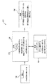
図1は、本明細書に開示される実施形態に係る、経皮的(percutaneously)に配置された刺激電極を含む移植可能刺激システムの模式図である。図1に示すように、本明細書の開示の一実施形態の移植可能刺激システム10の実施例は、患者20の胸部の中に外科的に設置できる移植可能パルス発生器(IPG)55と、IPG55の接続ポートの中に設置されたコネクタ(図示せず)を介してIPG55に電気的に接続された刺激リード線52と、を含んでいる。リード線52は、詳細に後述するように、刺激電極部65を含み、IPG55から延びて、患者10の舌下神経53のような所望の神経に接触するように刺激電極部65が配置されて、神経53を刺激できるようになっている。例えば、リード線52を利用してもよい例示的移植可能刺激システムは、クリストファーソン他に発行された米国特許第6,572,543号に記載されており、当該米国特許は参照により全体がそのまま本明細書に組み入れられる。一実施形態では、リード線52は、呼吸圧力などの呼吸努力を検出するために患者10内に設置された少なくとも1つのセンサ部60(IPG55に電気的に接続され、IPG55から延びている)をさらに含んでいる。
FIG. 1 is a schematic diagram of an implantable stimulation system that includes percutaneously placed stimulation electrodes according to embodiments disclosed herein. As shown in FIG. 1, an example of an
いくつかの実施形態では、目標神経を刺激する電極部の動作を開始させるために、センサ部60は呼吸パターン(吸気、呼気、呼吸休止など)を検知する。したがって、この配置によればIPG55(図1)がセンサ部60からのセンサ波形を受け取るため、IPG55は本明細書の開示の実施形態に合った治療計画に基づき、吸気(若しくは吸気に関わる呼吸パターンの別の態様)に同調して電気的刺激を送ることができる。また、センサ部60はIPG55によって駆動され、IPG55は、刺激リード線52からのインピーダンス信号を受信して処理する内部回路を有する。
In some embodiments, the
いくつかの実施形態ではセンサ部60は圧力センサであり、当該実施形態の一態様によれば、圧力センサは患者の胸部の圧力を検知する。別の態様によれば、検知された圧力が胸部の圧力と心臓の圧力(血流など)の組み合わせということもあり得る。この構成によれば、コントローラは、患者の呼吸パターンを検知するために圧力検知情報を分析するように構成されている。
In some embodiments, the
他のいくつかの実施形態では、センサ部60は1つの生体インピーダンスセンサ若しくは1組の生体インピーダンスセンサを備え、胸部以外の領域に配置することができる。ある態様によれば、そのようなインピーダンスセンサは生体インピーダンス信号若しくは生体インピーダンスパターンを検知するように構成されているため、制御ユニットは生体インピーダンス信号内の呼吸パターンを評価する。一実施形態では、生体インピーダンスの検知のために、電流が体内の電極部およびIPG55(図3A)のケースのうちの導電性部分を通じて付与される。このとき、インピーダンスを計算するために、2つの離れた刺激電極部間(あるいは1つの刺激電極部とIPG55のケースのうちの導電性部分との間)の電圧が測定されている。
In some other embodiments, the
いくつかの実施形態では、システム10は呼吸機能に関連する生理学的データをさらに得るための付加的なセンサを備える。例えば、システム10は経胸腔的生体インピーダンス信号、心電図(ECG)信号、若しくは他の呼吸関連信号を測定するために胸部領域に配置される様々なセンサ(例えば、図1のセンサ67、68、69など)を備えても良い。
In some embodiments, the
いくつかの実施形態では、閉塞性睡眠時無呼吸を処置するための検知・刺激システムは、閉塞性睡眠時無呼吸と診断された患者に対して治療的解決法を提供するための全体移植可能システムである。他の実施形態では、システムにおける1つ以上の構成要素が患者の体内へ移植されない。そのような非移植構成要素のうちいくつかの実施例(これに制限されない)は、外部センサ(呼吸、インピーダンスなど)、外部処理装置、若しくは外部電源を備える。当然のことながら、システムのうち移植された部分は、データの伝達を可能にする通信経路を提供し、および/部分と外部部分との相互間の信号を制御する。通信経路は、無線周波数(RF)遠隔リンク若しくは他の無線通信プロトコルを備える。 In some embodiments, a sensing and stimulation system for treating obstructive sleep apnea is generally implantable to provide a therapeutic solution for patients diagnosed with obstructive sleep apnea System. In other embodiments, one or more components in the system are not implanted into the patient's body. Some examples of such non-implantable components (including but not limited to) include external sensors (breathing, impedance, etc.), external processing devices, or external power sources. Of course, the implanted portion of the system provides a communication path that allows the transmission of data and / or controls signals between the portion and the external portion. The communication path comprises a radio frequency (RF) remote link or other wireless communication protocol.
部分的にあるいは全体的に移植可能な場合であっても、システムは吸気時に舌下神経を刺激するように設計されているため、睡眠中において上気道に障害若しくは閉塞が生じるのを防止することができる。一実施形態では、移植可能システムは移植可能パルス発生器(IPG)、末梢神経カフ(cuff)刺激リード線、および圧力検知リード線を備える。 Even when partially or fully implantable, the system is designed to stimulate the hypoglossal nerve during inspiration, thus preventing obstruction or obstruction of the upper airway during sleep Can do. In one embodiment, the implantable system comprises an implantable pulse generator (IPG), a peripheral nerve cuff stimulation lead, and a pressure sensing lead.
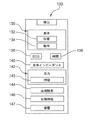
図2は、本明細書に開示される一実施形態に係る、移植可能刺激システム100を模式的に示すブロック図である。一実施形態では、システム100は図1のシステム10と少なくとも実質的に同じ機能および属性を含んでいる。図2に示すように、システム100は検出モジュール102、刺激モジュール104、治療モジュール106、および患者管理モジュール108を含んでいる。一実施形態では、治療モジュール106のIPG109は図1のIPG55と少なくとも実質的に同じ機能および属性を含んでいる。
FIG. 2 is a block diagram that schematically illustrates an
パラメータ配列を介して、検出モジュール102は、患者が就寝中か覚醒中かにかかわらず患者の呼吸状態を決定するために、さまざまな生理学的センサ(圧力センサ、血液酸素化センサ、音響センサ、心電図(ECG)センサ、またはインピーダンスセンサなど)からの信号、および他の呼吸関連指示計などからの信号を受信して追跡する。このような呼吸検出は、単一のセンサ、もしくは任意の多様なセンサのどちらから受信されてもよく、またはより信頼できより正確な信号を提供する可能性があるさまざまな生理学的センサの組み合わせから受信されてもよい。
Through the parameter array, the
例えば、一実施形態では、検出モジュール102は図3に示すように検出モニタ120を含んでいる。検出モニタ120は、位置検出構成要素132または動作検出構成要素134のうちの少なくとも1つを含む身体パラメータ130を含んでいる。一実施形態では、動作検出構成要素134は、歩行、身体動作、会話などを示す「地震」活動の検出(加速度計または圧電変換器による)を追跡する。他の実施形態では、位置検出構成要素132は、加速度計または他の変換器による身体位置または姿勢の検出を追跡する。いくつかの実施形態では、身体パラメータ130は、位置検出構成要素132と動作検出構成要素134の両方からの信号を利用する。
For example, in one embodiment, the
いくつかの実施形態では、検出モニタ120は、ECGパラメータ136、時間パラメータ138、生体インピーダンスパラメータ140、圧力パラメータ142、および血液酸素パラメータ144のうちの1つ以上をさらに追加的に含んでいる。一態様では、圧力パラメータ142は呼吸圧力構成要素143を含んでいる。一態様では、時間パラメータ142は一般的に時間を追跡する(例えば、時間間隔、経過時間など)が、他の態様では、時間パラメータ142は一般的な時間パラメータに加えて、または一般的な時間パラメータの代わりに、時刻を追跡する。他の態様では、時間パラメータ142は時刻に従って治療計画を開始したり、または停止したりするために使用できる。
In some embodiments, the
また、システム100(図2A)は、検出モニタ120の各パラメータ(例えば、血液酸素化パラメータ144など)のそれぞれにデータを提供するために、患者の身体内に移植された、または患者の身体に取り付けられた類似の生理学的センサ(例えば、LED型若しくは光学的な組織内かん流酸素飽和度など)を含んでいるか、または接続されているであろうということが分かる。また、いくつかの実施形態では、検出モニタ120は、舌下神経の幹および/または1つ以上の枝の仕様を含む舌下神経などの、刺激される予定の神経の活動に関する生理学的データを表す目標神経パラメータ146を含んでいる。また、さらに他の実施形態では、検出モニタ120に含まれる音響検出パラメータ147は、音響的に検出され呼吸努力を示す呼吸気流または心臓活動からの生理学的データを表す。
The system 100 (FIG. 2A) may also be implanted in or on the patient's body to provide data for each of the parameters of the detection monitor 120 (eg,
図2をさらに参照すると、システム100の治療管理装置106は、睡眠時無呼吸療法の開始、終了、および/または調整を本明細書に開示された原理にしたがって自動的に制御するように構成されている。また、治療管理装置106は、治療管理装置106にプログラムされた治療プロトコルに基づいて神経刺激信号の振幅、パルス幅、電極極性、継続時間、および/または周波数などのさまざまな治療パラメータを追跡して適用する。
With further reference to FIG. 2, the
一実施形態では、治療管理装置106は、少なくとも検出モジュール102と、治療管理装置106と、刺激モジュール104と、患者管理モジュール108と、を含むシステム100の動作を指示する制御信号を生成するように構成された1つ以上の処理装置および関連メモリを含んでいる。特に、検出モジュール102を介して収集された生理学的データに対応して、コントローラに関連するメモリ内に含まれる入力および/または命令を通じて受信されたコマンドに呼応して、または基づいて、治療管理装置106は刺激モジュール104の動作を指示する制御信号を生成して、舌下神経などの目標神経の刺激を選択的に制御し、気道開通性を回復させ、それにより無呼吸イベントを低減したり、または除去したりする。
In one embodiment,
この点を考慮すると、治療管理装置106は呼吸情報を合成する役割を果たしており、その呼吸情報に基づいて好適な刺激パラメータを決定して、電気刺激を目標神経に導く。無呼吸を検出するためにいろいろな生理学的パラメータを使用しても効果がまちまちである可能性があるが、本明細書に開示された一実施形態では、検出モジュール102は胸部の生体インピーダンスパラメータを介して無呼吸を検出する。特に、胸部インピーダンスの測定値は呼吸波形の相対振幅を追跡するために使用される。生理学的に言えば、肺が空気でいっぱいになったり空になったりするとき、肺の生体インピーダンスは変化する。したがって、胸部インピーダンスは息を吸う間は増加して、息を吐く間は減少する。また、他の態様では、呼吸ドライブの変動が生体インピーダンスの振幅の変動を引き起こすことになり、大きな呼吸ドライブが生体インピーダンスの信号振幅を増加させる。
Considering this point, the
生体インピーダンス信号が得られると、生体インピーダンス信号は時間についての平均ピーク振幅を特定するために、さらに処理される。無呼吸は、典型的な無呼吸イベントの既知の継続時間と実質的に類似の時間の間に生じる周期的な振幅変動をさらに特定することにより検出される。 Once the bioimpedance signal is obtained, the bioimpedance signal is further processed to identify an average peak amplitude over time. Apnea is detected by further identifying periodic amplitude variations that occur during a time substantially similar to the known duration of a typical apnea event.
この応用のために、用語「処理装置」は、メモリ内に含まれる命令列を実行する現在開発されている、または将来開発される処理装置を意味するものとする。命令列を実行することにより、処理装置に制御信号の生成などのステップを実行させる。命令は、処理装置で実行するために、コントローラに関連するメモリにより代表される読み出し専用メモリ(ROM)、大容量記憶装置、または他の何らかの永続記憶装置からランダム・アクセス・メモリ(RAM)にロードされてもよい。他の実施形態では、記載の機能を実現するために、ソフトウェア命令の代わりに、またはソフトウェア命令と組み合わせて配線回路を使用してもよい。例えば、1つ以上の特定用途向け集積回路(ASIC)の一部としてコントローラを具体化してもよい。特に断りのない限り、コントローラはハードウェア回路およびソフトウェアのいかなる具体的な組み合わせにも限定されず、処理装置で実行される命令のいかなる特定のソースにも限定されない。 For the purposes of this application, the term “processor” shall mean a processor that is currently being developed or will be developed in the future that executes the sequence of instructions contained in the memory. By executing the instruction sequence, the processing device executes steps such as generation of a control signal. Instructions are loaded into random access memory (RAM) from a read-only memory (ROM), mass storage device, or some other persistent storage device, represented by the memory associated with the controller, for execution on the processing unit May be. In other embodiments, wiring circuitry may be used in place of or in combination with software instructions to implement the described functionality. For example, the controller may be embodied as part of one or more application specific integrated circuits (ASICs). Unless otherwise noted, the controller is not limited to any specific combination of hardware circuitry and software, and is not limited to any particular source of instructions to be executed on a processing device.
一般論として、システム100の刺激モジュール104は、医師により、および/または治療管理装置106と提携してプログラムされた治療計画に基づいて、(刺激電極65のような)電極を通じて神経刺激信号を生成して印加するように構成されている。
In general terms, the
一般論として、患者管理モジュール108は当業者によく知られた方法でIPG109への、およびIPG109からの通信を促進するように構成されている。したがって、患者管理モジュール108はIPG109の活動(検出された生理学的データ、刺激履歴、検出された無呼吸の回数などを含む)を報告するように構成されているとともに、患者管理モジュール108は患者プログラマ、臨床医プログラマなどの外部ソースからIPG109の初期のまたは追加的なプログラムを受け取るように構成されている。
In general terms,
本明細書の開示の少なくとも1つの実施形態にしたがって、図4の平面図に経皮デリバリーシステム201の刺激場所探知ツール200が図式的に示されている。一般論として、場所探知ツール200は、目標となる若しくは最適な刺激場所を識別することと目標刺激場所近くに刺激リード線を経皮的に運搬することを促進するように構成されている。図4に示すように、場所探知ツール200はハンドル212から延びる針210を備える。針210は、先端214と、針本体216と、針本体216沿いに延びる一連の深さマーカー218とを備える。針210は先端214からハンドル212を通じて基端側に延び、基端219で終了する。基端219において、接続ポート236は、針210と(以降で詳細に説明する)刺激モニタとの間における開放可能な電気的接続を可能とし、先端214における電気的刺激信号を提供する。
In accordance with at least one embodiment of the present disclosure, the top view of FIG. 4 schematically illustrates the stimulation
図4を再度参照すると、一態様によれば針本体216は外部表面に誘電コーティングを有し、一方で、先端214の導電性表面が露出されることにより先端214と体内の組織との電気伝導が可能となる。深さマーカー218は視認することができ、いくつかの実施形態ではX線写真および/又は超音波による視認技術で容易に視認することができる材料で構成される場合がある。
Referring back to FIG. 4, according to one aspect, the
さらに、本明細書の開示の実施形態にしたがって、場所探知ツール200や刺激電極部の位置の特定、および刺激リード線の経皮的デリバリーに含まれる他の構成要素の位置の特定を補助するために様々な外科的視認技術を用いることができる。
Further, in accordance with embodiments of the disclosure herein, to assist in locating the
場所探知ツール200を(刺激モニタと共同して)舌下神経近傍の様々な場所に経皮的に挿入することにより、これら様々なテスト位置におけるテスト刺激信号の利用により観察される神経筋反応などの神経反応の種類および大きさに基づき、舌下神経の経路が特定される。このように、質的神経捕獲(quality nerve capture)を示す神経筋反応を表示するこれらの試験位置は、刺激リード線の刺激電極部を配置すべき最適な若しくは目標となる場所を特定するために利用される。これらの観察された反応は、経皮的アクセスが開始される肌の挿入ポイントを特定するためにも利用される。
By inserting the
いくつかの実施形態では、神経刺激信号は、図1に示される(刺激電極部65参照)ように舌下神経沿いの単一の刺激場所に適用される。しかしながら、他の実施形態では、睡眠時無呼吸治療の神経刺激信号は舌下神経沿いに長手方向(縦方向)に間隔の空けられた複数の場所のうち2つ以上から適用される。このような配置によれば、分離し、間隔の空けられた刺激電極部を同時若しくは異なる時間に作動させることができる。このことを考慮して、経皮的アクセス方法を舌下神経沿いの1つ以上の場所を示すように適用することにより、複数の異なる刺激電極部についてその配置を特定することができる。 In some embodiments, the neural stimulation signal is applied to a single stimulation location along the sublingual nerve as shown in FIG. 1 (see stimulation electrode portion 65). However, in other embodiments, sleep apnea therapy neural stimulation signals are applied from more than one of a plurality of longitudinally spaced locations along the hypoglossal nerve. With such an arrangement, the separated and spaced stimulation electrode portions can be operated simultaneously or at different times. With this in mind, the percutaneous access method can be applied to indicate one or more locations along the hypoglossal nerve to identify its placement for a plurality of different stimulation electrode portions.
図4をさらに参照すると、場所探知ツール200と共同して、神経一体型モニタ250(スタンドアロンモニタ、または図2のプログラマ108のような睡眠時無呼吸医師プログラマ108に組み込まれたモニタ)のような刺激モニタが、コネクタ237を経由して場所探知ツール200に接続される。刺激モニタは、場所探知ツール200を経由して付与される刺激を通じて電極を適切な位置に配置する際に医師を助けるように使用される。一実施形態では、IPG55(図1)若しくはIPG109(図2)を刺激モニタとして用いることができる。いくつかの実施形態では、スタンドアロン神経一体型モニタ250は2001年12月25日付で発行された術中神経電気生理学的モニタと題する米国特許第6,334,068号に記載された神経一体型モニタと少なくとも実質的に同じ機能および属性を含み、当該米国特許は参照することにより全体がそのまま本明細書に組み入れられる。他の実施形態では、他の神経一体型モニタまたは同等な機器配列(例えば、刺激プローブおよび筋電図検査システムなど)が、刺激信号を印加して目標神経に神経支配された筋の反応を評価するために使用される。
Still referring to FIG. 4, in conjunction with the
図4に示されるようにいくつかの実施形態では、神経一体型モニタ250は、刺激モジュール252と、筋電図検査モニタ電子機器(EMG)256を含む反応モジュール254と、を含んでいる。さらに、図4は、本明細書の開示の一実施形態による反応評価配列275を示す。反応評価配列275は、目標神経を刺激する目標場所の有効性を評価して刺激電極部の経皮的運搬を行う入口点を特定するための1つ以上の機構を提供する。一実施形態では、潜在的な目標場所に刺激を付与すると、反応配列275は、(1)舌の突出278(矢印Pで示す)の程度および位置(舌先の伸長よりも舌根の伸長の方が好ましい)を観察または測定すること、(2)上部呼吸気道277の増加した断面積の範囲(矢印Wで示す)を内視鏡、超音波、若しくは他の視認技術を用いて観察または測定すること、(3)(モニタ250のEMG機器256で測定される)1つ以上の筋のEMG反応280の程度を測定することを含む。
As shown in FIG. 4, in some embodiments, the integrated
したがって、この点を考慮して、モニタ250と、反応配列275の1つ以上の態様とは、目標神経上の潜在的刺激場所に対する場所探知ツール200の位置決めを評価するために使用される。一態様では、場所探知ツール200を目標神経近傍の様々な位置の中および目標神経の中に経皮的に挿入しながら、反復刺激パターンが神経一体型モニタ250の刺激モジュール252から場所探知ツール200の先端214に付与される。いくつかの実施形態では、付与される刺激パターンは、3秒に一度の1秒間の刺激バースト、傾斜刺激パターン、および/または医師が管理するバーストである。別の態様では、神経一体型モニタ250の筋電図検査(EMG)モニタ電子機器256は、場所探知ツール200の経皮的反復挿入中に付与される神経刺激に対する筋反応を測定できるようにする。したがって、図4にさらに示されるように、細線電極282(または類似電極)が神経一体型モニタ250のEMG機器256と電気通信可能に接続され、場所探知ツール200を通じて付与される刺激パターンに対応する筋活動を連続的に監視するために使用される。この配置を用いると、この閉ループフィードバックにより、医師は場所探知ツール200の(舌下神経に対する)位置のリアルタイムフィードバックと、経皮的に移植された電極リード線が目標神経を捕捉する可能性に関するフィードバックと、を得ることができる。
Thus, in view of this point, the
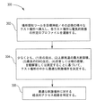
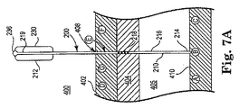
図5に示すように本明細書の開示の一実施形態では、無呼吸治療工程は舌下神経の長さ方向沿いに刺激電極部65(図1)を配置すべき最適な場所を識別する工程を含み、これにより結果的に舌下神経に対する所望の刺激および睡眠時無呼吸の処置がなされる。特に、図5に示す302のように、場所探知ツール200は舌下神経若しくは舌下神経の周囲における様々なテスト刺激位置へ(皮膚を通じて目標神経に向かって)経皮的に挿入される。例えば、図7Aのダイアグラム400にさらに示すように、針210は経皮的アクセス経路408を通じて延び、ハンドル212が皮膚表面402の外部にある状態で、先端214は複数の潜在的刺激場所(例えばA、B、Cなど)のうちの1つにおいて神経410と電気的に接続する。外科的ナビゲーション技術を経由して、目盛りマーカー218は神経410を取り囲んでいる皮膚402および他の皮下組織404、405を通じた挿入深さの測定を可能にする。図4および7Aは説明のために前記のマーカー218を少しだけ示しているが、マーカー218は針210の長さ分若しくは実質的にその長さ分延びている場合もあり、また、マーカー218の間隔は図4および7Aに示されるものと異なる場合もある。ツール200の各種構成要素および周囲に存在する組織は、説明のために拡大および/又は最小化されている。
In one embodiment of the present disclosure as shown in FIG. 5, the apnea treatment step identifies the optimal location where the stimulation electrode portion 65 (FIG. 1) should be placed along the length of the hypoglossal nerve. This results in the desired stimulation of the hypoglossal nerve and sleep apnea treatment. In particular, as shown at 302 in FIG. 5, the
各テスト場所において、電気的刺激の所定のプロファイルが、舌下神経上の最適な若しくは好ましい1つ以上の目標場所を識別するために適用される。図5の304で示すように、最適な若しくは好ましい目標場所は、少なくとも以下の事項を観察若しくは測定することによりテスト場所の中から特定される。その事項とは(1)舌の突出の程度、(2)上部気道の断面積の大きさ、(3)気道の開通性が維持されていることを示す最も良いEMG反応、(4)非目標筋肉の反応欠如、(5)舌筋および/又は喉頭筋のけいれん、である。一態様では、最適な若しくは好ましい目標刺激場所は吸気時における気道開通性の維持の最大衝撃に相関性がある。目標場所を特定した後、工程300は目標場所への経皮的アクセス経路を特定する工程を含む。一態様によればこの工程は皮膚侵入場所(例えばD、E、F、Gなど)を特定する工程を含み、皮膚侵入場所は舌下神経上の目標刺激場所の直接上方にある場合とない場合がある。最終的に、これらのステップ302ー306は、目標神経沿いの全ての最適な刺激位置を特定するまで必要であれば反復して繰り返し行うことが可能である。 At each test location, a predetermined profile of electrical stimulation is applied to identify one or more optimal or preferred target locations on the hypoglossal nerve. As indicated at 304 in FIG. 5, the optimal or preferred target location is identified from among the test locations by observing or measuring at least the following items. The items are (1) degree of tongue projection, (2) size of upper airway cross-sectional area, (3) best EMG response indicating that airway patency is maintained, (4) non-target Lack of muscular response, (5) convulsions of the tongue and / or laryngeal muscles. In one aspect, the optimal or preferred target stimulation location is correlated to the maximum impact of maintaining airway patency during inspiration. After identifying the target location, step 300 includes identifying a percutaneous access route to the target location. According to one aspect, this step includes identifying a skin entry location (eg, D, E, F, G, etc.), where the skin entry location may or may not be directly above the target stimulation location on the hypoglossal nerve. There is. Finally, these steps 302-306 can be repeated iteratively if necessary until all optimal stimulation locations along the target nerve have been identified.
一態様では、様々なテスト刺激場所を評価する際に、測定された反応の大きさは場所探知ツール200が舌下神経にどれだけ近いかおよび/又は舌下神経のどの部分が刺激されているかを示す。例えば、場所探知ツール200と舌下神経との距離、および測定された反応の強さは指数関係の減少で表される。別の言い方をすれば、舌下神経からの距離が増加すれば測定された反応の大きさは指数的に減少するということである。一態様によれば、距離とは舌下神経の経路に対して3次元的に測定された距離を意味し、あらゆる所定のテスト場所は、目標神経の長手方向軸に対して略垂直に延びる短手方向距離、(2)目標神経に対する垂直距離、(3)目標神経の長手方向軸に対して略平行に延びる長手方向距離、を含む。このことを考慮して、複数の潜在場所がテストされるとテスト場所の中から最良の若しくは最適な刺激場所を強調するパターンが特定される。さらに、テスト刺激に加えて他の外科的ナビゲーション技術を利用して、反応が測定されたときの目標解剖学的環境内における場所探知ツール200を視認可能とすることにより最適な/好ましい刺激場所をさらに正確に示すこともできる。
In one aspect, when evaluating various test stimulation locations, the magnitude of the measured response is how close the
いくつかの実施形態では、舌下神経沿いの複数の潜在的刺激場所を評価する際に、工程300は各潜在的刺激場所において刺激信号として各信号パラメータ(例えばパルス幅、電極の極性、周波数、継続時間、および振幅など)の値が異なる所定の電気的刺激を付与することにより、どの値の組み合わせによって潜在場所の目標神経に対する刺激信号の最良の衝撃が得られるかを決定する。このように、各潜在場所は、刺激すべき最適な場所として選ばれる潜在場所に刺激信号が実際に付与されるであろうという条件の下で評価される。一実施形態では、各刺激パラメータを評価することにより最適な刺激場所を決定する際には、図1−4に関連して前述したように刺激モジュール104、場所探知ツール200、および患者プログラミングモジュール108と共同で(IPG109を含む)治療モジュール106を採用する。
In some embodiments, when evaluating a plurality of potential stimulation locations along the hypoglossal nerve,
一態様によれば、場所探知ツール200により特定された最適な刺激場所が保存されることにより、刺激リード線の刺激電極部を正確にその場所へ運ぶことが可能になる。したがって、いくつかの実施形態では、針210を舌下神経沿いの最適場所における挿入位置に維持しながらも、先端214を神経410との結合状態に維持した状態でハンドル212が針本体216から離脱される。次に、後で詳細に説明するようにリード線案内ツールが場所探知ツール200の針210の基端部219を越えて進められ、図7Bに示す配置となる。
According to one aspect, the optimal stimulation location identified by the
一般論として、刺激リード線が経皮的に挿入されることにより結果として刺激リード線の先端位置が神経の目標刺激場所の近傍に近づく。いくつかの実施形態では、案内機構は、目標刺激場所への経皮的アクセス経路を開始および発達させるとともにその経路を通じた刺激リード線の案内を促進するために用いられる。様々な異なるリード線案内ツールの形状および種類を用いることが可能である一方で、図6Aはリード線案内ツール350の1つの例示的な実施形態を示す。図6Aに示すように、リード線案内ツール350はハンドル362を通るとともにハンドル362に支持されるカニューレ360を備える。カニューレ360は湾曲した先端部375を備え、本体部366はハンドル362内において先端部375から基端部369に延びる。一態様によれば、カニューレ360は、所望の挿入深さの測定を可能にするために一連の目盛り深さマーカー368を備える。図6Aおよび7Bは説明のために前記のマーカー368を少しだけ示しているが、マーカー368はカニューレ360の長さ分若しくは実質的にその長さ分延びている場合もあり、また、マーカー368の間隔は図6Aおよび7Bに示されるものと異なる場合もある。いくつかの実施形態では、少なくともいくつかの深さマーカー368がX線不透過性の材料で形成されることにより、蛍光透視法若しくは他の視認技術による視認が可能となり、目標となる神経および/又は他の組織、構造などに対するカニューレ360の正確な方向、位置、および配置が確保される。カニューレ360、針210の少なくともいくつかの導電性部分が蛍光透視法若しくは他の視認技術の下で視認されることにより、これらの各要素の正確な配置、方向、および/又は位置の確保がさらに補助される。
As a general rule, the stimulation lead is inserted percutaneously, and as a result, the tip position of the stimulation lead approaches the vicinity of the target stimulation location of the nerve. In some embodiments, the guidance mechanism is used to initiate and develop a percutaneous access path to the target stimulation location and facilitate guidance of the stimulation lead through that path. While various different lead guide tool shapes and types can be used, FIG. 6A shows one exemplary embodiment of
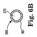
図6Bの断面図に示すように、カニューレ360は本体部366の中を延びる内腔370を形成している。一般論として、カニューレ360は電気的導電性を有する略チューブ(管)状の構造である。したがって、図6Bに示すように一態様によれば、本体部366はその外部表面に誘電性若しくは絶縁性のコーティング367を有し、一方でカニューレ360の先端364では誘電性コーティングが省略されている。
As shown in the cross-sectional view of FIG. 6B,
一実施形態では、先端364は、刺激リード線によるその中の通過を容易にするように大きさおよび形状の定められた端部開口390を有する。さらに、湾曲した先端部372は略弾性で柔軟な材料で形成される。したがって、図4および7Aに示されるように、既に配置された場所探知ツール200を越えてカニューレ本体366がスライドして前進されると、湾曲した先端部372は略一直線の形状をとり、図7Bに示されるように舌下神経に対して略垂直な方向における皮膚402および組織404、405を通る経皮的な挿入が補助される。さらに、この位置ではツール350の基端部および/又はハンドル362は皮膚表面402の外部に残ったままである。いくつかの実施形態では場所探知ツール200がなく、当業者に知られた補強材(stiffener)若しくは探り針を用いることにより経皮的挿入時におけるカニューレ本体366を直線的な形状に維持することができる。そのような探り針の一般的な一実施例はバックバーグの米国特許第5,226,427号に記載されており、当該米国特許は参照により全体がそのまま本明細書に組み入れられる。
In one embodiment, the
直線的にされたその形状において、カニューレ310は、後で図6Cとの関連で説明するツール380について示されるものと実質的に類似の形状を有する。再度図6Aを参照すると、一旦先端364が所望の深さに配置されれば、場所探知ツール200(若しくは他の補強剤)は、湾曲した先端部372が図7Cで示すように緩んで概ね湾曲形状に戻るように離脱される。この緩み(relax)により、先端部開口378は図7Cで示すように舌下神経410に対して略平行な方向を向くため、刺激リード線を所望の刺激場所に向かって舌下神経沿いにスライドして前進させるのに適切な位置をとることができる。いくつかの実施形態ではそのように緩んだ後、先端部開口378はカニューレ310の略直線的な基端部に対して概ね鈍角を向く。
In its straightened shape, cannula 310 has a shape that is substantially similar to that shown for
いくつかの実施形態では、当業者であれば分かるように、複数の潜在場所(例えばA、B、Cなど)の中から最適な刺激場所(A)を特定するとき、場所探知ツール200を用いることにより図7A−7Eに示すように最適な刺激場所(例えばAなど)の先端側若しくは基端側にあるリード線案内ツールの対応する侵入ポイント(例えばD、E、F、Gなど)を特定する場合もあると予想される。一実施形態では、皮膚表面における侵入場所(例えばEなど)と舌下神経上の最適な刺激場所(A)との(舌下神経に略平行な軸に沿った)間隔は、挿入されたカニューレ本体部366による(舌下神経に対する)略垂直方向から先端部開口378が伸びる距離(D1)に実質的に等しい。
In some embodiments, as will be appreciated by those skilled in the art, the
別の実施形態では、皮膚侵入ポイントと最適な刺激場所との間隔は、刺激リード線の電極部を目標刺激場所に運ぶために端部開口378から外側に出たと予想される(破線395で表される電極部を含む)刺激リード線の長さ(図6AのD2で表される)に相当するように構成されている。この配置によってさらに、刺激リード線の電極部の最終的な配置と既に特定されている最適な若しくは目標となる刺激場所(例えば、図7A−7Eに示すA)とを正確に対応することが確保される。しかしながらいくつかの実施形態では、刺激リード線の先端部が目標刺激場所を越えて距離D2延びるように配置されることにより、目標刺激場所が刺激リード線の電極部(例えば、後に図8A−8Cに関連して説明される電極部440の電極アレイ442など)の長さ沿いに略中央に位置したままであることが確保される。このような実施形態では、距離D2は電極部の長さ以下の長さに相当し、電極部(例えば、図8A−8Cに示す電極部440の電極アレイ442)の長さよりも小さい長さ(例えば、おおよそ1/4、1/2、3/4など)に相当する可能性もある。
In another embodiment, the distance between the skin entry point and the optimal stimulation location is expected to have exited from the
したがってこの実施形態では、皮膚侵入ポイントと最適な刺激場所との(本領域にある舌下神経の長手方向軸に略平行な軸に沿った)全体の間隔は、距離D1と距離D2との合計であると予想される。このことを考慮して一実施形態では、場所探知ツール200により最適な刺激場所(例えば、A、B、Cの中からA)を特定した後に、場所探知ツール200を用いて舌下神経の経路(若しくは他の適切な解剖学的ランドマーク)を追跡して、最適な刺激場所(例えば、図7A−7Bに示すA)から距離D1および距離D2の合計離れたリード線案内ツール350用の皮膚侵入ポイント(例えば、図7A−7Bに示すE)を特定する。
Thus, in this embodiment, the total distance between the skin entry point and the optimal stimulation location (along an axis substantially parallel to the longitudinal axis of the hypoglossal nerve in this region) is the sum of distance D1 and distance D2. Is expected. In consideration of this, in one embodiment, after the optimal stimulation location (for example, A among A, B, and C) is specified by the
一態様によればこれらの距離D1およびD2を追跡することにより、刺激されるべき舌下神経が存在する領域において重大な解剖学的構造(例えば、骨状管、隆起物など)が相対的に不存在なおかげで、最適な刺激場所へ届くように刺激リード線の案内が大幅に強化される。 According to one aspect, tracking these distances D1 and D2 allows relative anatomy (eg, bony ducts, ridges, etc.) to be relatively located in the region where the hypoglossal nerve to be stimulated is present. Thanks to the absence, the guidance of the stimulation leads is greatly enhanced to reach the optimal stimulation location.
別の実施形態では、(図6Cに示す)リード線案内ツール380は、図6Aに示される湾曲した先端部372および端部開口378の代わりに横開口390を有する直線的先端部382を備える点を除き図6A−6Bのリード線案内ツール350と実質的に同じ機能および属性を含んでいる。したがってこの実施形態によれば、直線的先端部382は刺激リード線の先端部によるその中の通過を容易にするように大きさおよび形状の定められた横開口390を有する。一態様によれば、開口390は短手方向に向けられた、内腔370の非コアリング開口として構成される。この配置によれば経皮的挿入をすると、ツール380のカニューレ本体360は皮膚および舌下神経に対して略垂直方向を向く。このとき、横開口390によって、舌下神経に対して略平行に前進されるように刺激リード線が本体360の方向に対して略鈍角に延びるとともに舌下神経に対して略平行に伸びる経路を出て行くことが可能となっている。
In another embodiment, the lead guide tool 380 (shown in FIG. 6C) comprises a
リード線案内ツール380を用いるときは、先端部382(先端384を含む)が直線形状であり、リード線案内ツール380が最適な刺激場所の上へ舌下神経に対して略垂直方向に向けられるため、図6Aおよび7C−7Eに示す距離D1は一般的に追跡されない。しかしながら一態様では、刺激リード線の電極部は開口390を通じて先端384から概ね外側(かつカニューレ本体360の長手方向軸に対して略垂直)に延びると予想されるので、刺激リード線の電極部の長さを選択的に決めることができる。したがって、リード線案内ツール380の実施形態では、場所探知ツール200により最適な刺激場所(例えば、図7A−7Eに示すA)を特定することに加えて、操作者は最適な刺激場所から距離D2離れた皮膚侵入ポイント(例えば、図7Cに示すG)を特定すると予想される。距離D2は、刺激リード線の電極部を目標刺激場所に運ぶために横開口390から外側に出たと予想される(電極部を含む)刺激リード線の長さに概ね相当する。このようにして操作者は、特定された目標刺激場所(例えばA)へ刺激リード線の電極部が正確に運ばれることを確保する。前述のように、距離D2が電極部(例えば、図8Bに示す電極アレイ442など)の長さ以下の長さを有することにより目標刺激場所に対して電極部を中心に置くことが確保されると予想される。
When using the
いくつかの実施形態では、刺激リード線(例えば、少なくとも図8A−8Eとの関連で説明する刺激リード線430)は、カニューレ380を通じた、および目標刺激場所を取り囲む組織を通じた刺激リード線の前進を促進させるために着脱可能な探り針と協同可能に構成されている。特に、刺激リード線の先端部が横開口410を出たら、先端部436は周囲の組織を貫通するように前進しなければならない。このことを考慮して、探り針は刺激リード線が目標刺激場所まで貫通するような硬さを有しており、刺激リード線が正確に配置されると、探り針は刺激リード線との接続から離脱する。さらにいくつかの実施形態では、この探り針は刺激リード線の電極部に関連する固定機構を選択的に配置するためにも使用される。
In some embodiments, the stimulation lead (eg,
いくつかの実施形態では、リード線案内ツール350若しくはリード線案内ツール380のカニューレは概ね非導電性であり、場所探知ツール200および/又は補強剤の導電性要素は、目標刺激場所および/又は目標刺激場所から離れた皮膚侵入ポイントの位置を確かにするために電気的導電性経路として用いられる。
In some embodiments, the cannula of the
いくつかの実施形態では、他の種類の案内機構が刺激リード線用の経皮的アクセス経路を確立するために用いられる。例えば1つの案内機構は、ガイドワイヤと、カニューレおよび探り針を有する針とを備える。この配置によれば、針カニューレが経皮的に挿入されることにより、探り針による針カニューレの操作、ガイド、および/又は固定という補助を受けながら経皮的経路を確立する。カニューレおよび探り針の組み合わせによる経路の確立後、探り針は離脱される。カニューレは所定位置のままで、ガイドワイヤは、カニューレの基端部の中に挿入されてガイドワイヤの先端部が目標刺激場所に近接するまでカニューレ中を前進される。次に、ガイドワイヤは所定位置のままで、針のカニューレ部分はガイドワイヤから基端方向へ離脱される。既知の技術を用いることにより、刺激リード線は、ガイドワイヤに開放可能に結合され、刺激リード線の電極部が目標刺激場所に近接するまで確立された経皮的アクセス経路を通ってガイドワイヤの中を前進される。刺激リード線は所定位置のままで、その後ガイドワイヤは離脱される。最終的に刺激リード線は、電極部と神経の目標刺激場所との電気的結合関係を維持するように固定される。 In some embodiments, other types of guidance mechanisms are used to establish a percutaneous access path for the stimulation lead. For example, one guide mechanism includes a guide wire and a needle having a cannula and a probe needle. According to this arrangement, the needle cannula is inserted percutaneously to establish a percutaneous pathway with the assistance of manipulation, guide and / or fixation of the needle cannula with the probe needle. After the path is established by the cannula and probe combination, the probe is disengaged. With the cannula still in place, the guide wire is inserted into the proximal end of the cannula and advanced through the cannula until the distal end of the guide wire is close to the target stimulation location. The guide wire is then left in place and the cannula portion of the needle is proximally detached from the guide wire. Using known techniques, the stimulation lead is releasably coupled to the guide wire and the guide wire is routed through the established percutaneous access path until the electrode portion of the stimulation lead is proximate to the target stimulation location. Advances inside. The stimulation lead remains in place and then the guide wire is removed. Finally, the stimulation lead is fixed so as to maintain an electrical coupling relationship between the electrode portion and the target stimulation location of the nerve.
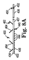
本明細書の開示の方法およびシステムでは各種の異なる形状および構成のリード線を用いることができるが、図8A−8Cは、経皮的に配置されるよう構成された刺激リード線430の例示的一実施形態を示す。一実施形態では、(図4−7との関連で前述したように)刺激リード線430はツール200、350、380を経由して運ばれ、その一方で他の実施形態では、その他の低侵襲運搬技術によって運ばれる。刺激リード線430の運搬についての各種態様は本明細書でより詳細に説明する。
Although various different shapes and configurations of leads can be used in the disclosed methods and systems, FIGS. 8A-8C are exemplary stimulation leads 430 configured to be placed percutaneously. One embodiment is shown. In one embodiment,
図8A−8Cに示すように、刺激リード線430は正面部432と裏面部434とを備え、先端部436と基端部438との間に延びる。
As shown in FIGS. 8A-8C, the
先端部436において、正面部432は、電極444の第1のアレイ442を有する電極部440を支持する。一般論として、電極部440の実質的に全体の長さは略平坦な表面で構成され、裏面部434も略平坦な表面を形成するときには、電極部440を形成する先端部436の全体が、(裏面部434上の突起464を例外として)略平坦な若しくは略平面的な部材で構成される。
At the
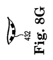
(刺激電極部440を含む)先端部436の略平坦な若しくは略平面的なこの構成によれば断面地形が小さいので、舌下神経を取り囲む組織の中を前進することが促進される。加えて、先端部436の正面部432が少なくとも略平坦な表面を有することにより、刺激電極部440と舌下神経の表面との界面が非常に近くかつ効果的なものになる。しかしながら他のいくつかの実施形態では、先端部436の正面部432は、略平坦ではないが少なくともいくつかの湾曲部分若しくは波状部分を有する。図8Fに示されるように一実施例では、先端部436の正面部432の湾曲部分が略凹形の形状を形成し、当該形状は、電極部440が舌下神経の外部表面の略弓形の形状に相互に適合する程度を強調するように構成されている。図8Gに示されるように別の実施例では、先端部436の正面部432は略凸形の形状を形成する。別の態様によれば、この略凸形状は、最適な刺激場所へ到達するための舌下神経を取り囲む組織の中を通る先端部用のスライド可能な経路を強調するように構成されている。
According to this substantially flat or substantially planar configuration of the tip 436 (including the stimulation electrode portion 440), the cross-sectional topography is small, so that advancement in the tissue surrounding the hypoglossal nerve is facilitated. In addition, the
同様にいくつかの実施形態では、先端部436の裏面部434は略平坦ではないが、凹形若しくは凸形になりうる少なくともいくつかの湾曲部分を有する。一態様によれば、裏面部434上の略凸形の形状は、目標刺激場所へ到達するための舌下神経を取り囲む組織の中を通る先端部用のスライド可能な経路を強調するように構成されている。
Similarly, in some embodiments, the
別の態様によれば、正面部432が電極部440を保持するため、先端部436の裏面部434は電気的絶縁性の材料によって略形成されているか若しくは電気的絶縁性の材料でコーティングされている。この配置によれば、裏面部434がシールドとして効果的に機能することにより、刺激信号が刺激場所を覆っている知覚神経および皮膚に対して影響することを防止する。
According to another aspect, since the
別の態様によれば、刺激リード線430の基端部438において、電極452の第2のアレイ450は刺激リード線430の正面部432および裏面部434の両方に形成される。電極444の第1のアレイ442は電極452の第2のアレイ450へ電気的に接続され、電極452の第2のアレイ450はIPG(図1の55若しくは図2の109)への電気的接続を提供するように構成されている。IPG55からの制御により、刺激電極部440の各電極444は、選択的に制御可能な極性、振幅、周波数、パルス幅、および/又は継続時間を有する刺激信号を付与できるように独立してプログラム可能である。
According to another aspect, at the
一実施形態では、電極444の第1のアレイ442は、保護カソード電極極性配置における少なくとも3つの電極による短手方向成分(すなわち、幅W1に沿って延びる)若しくは長手方向成分(すなわち、長さL1に沿って延びる)を備える。この保護カソード電極極性配置は舌下神経付近の組織を過分極化する一方で、刺激リード線430の電極部440付近における多くの舌下神経を完全に脱分極化する。しかしながら図8Bに示されるようにいくつかの実施形態では、第1のアレイ442は電極部440の幅方向および長さ方向に延びる多数(実質的に3以上)の電極444を備える。この配置によれば第1のアレイ442の中から異なる組み合わせの電極444を選択することができるため、第1のアレイ442内における電極444を最適な組み合わせとすることにより舌下神経の刺激を最適化することができる。さらにいくつかの実施形態では、1つ以上の電極444が形状および/又はピッチを変えられたり、あるいは電極444の列をジグザグにすることにより1つ以上の電極444が変更されている。
In one embodiment, the
いくつかの実施形態では、目標刺激場所の領域における目標神経の直径が約3mmであると想定して、電極部440は少なくとも約5mmの幅(図8BのW1)を有する。したがってこれらの実施形態では、電極部440の幅(W1)は、少なくとも目標刺激場所の領域における目標神経の直径に実質的に等しいか若しくは大きい。この関係により、目標神経の実質的に全ての軸索が(付与される刺激信号のパラメータに基づいて)潜在的に活性化されるように(睡眠時無呼吸を治療するための)電気的刺激信号が神経の全断面に作用するということが確保される。
In some embodiments, assuming that the target nerve diameter in the region of the target stimulation location is about 3 mm, the
本体部437は(先端部436における)電極部440と基端部438の間を延びる。電極444を除き、本体部437は正面部432および裏面部434で電極を持たない略絶縁性の部材である。当然のことながら、ワイヤが本体部437の内部を延びることにより電極444がIPG(図1の55若しくは図2の109)へ接続される。一般論として、本体部437は電極部440からIPG55(図1)まで延びるのに十分な長さを有する。
The
いくつかの実施形態では、刺激リード線430の先端部436は、裏面部434上すなわち刺激電極部440に対して反対側の面上に配置される固定機構462を備える。一態様によれば、固定機構462がカフのない配置をとることにより、固定機構462は神経に面さないように電極部440の反対側に配置された状態で、電極部440を神経の近傍に固定することができる。このような配置により、神経に対して圧力やその他の機械的効果を付与することなく、電極部を神経とは独立しながら神経に対して所望の位置に固定することができる。
In some embodiments, the
一態様によれば、固定機構462は少なくとも1配列(one array)の突起を備える。一実施形態では、突起464は弾性材料で形成されたフラップである一方、他の実施形態では、突起464は返し(barb)、先が分岐したもの(prong)、若しくは他の固定部材である。これらの実施形態のうちいくつかでは、刺激リード線430の先端部436をさらに固定するために突起および突起の近傍にて線維性成長を誘発するように、突起の大きさおよび形状が決められている。一態様によれば、約1ヶ月以内に突起464は線維性組織とともに内側に成長する。したがって、突起464は体内における刺激リード線430の位置をより長期間安定化するように機能するが、突起464の1つの目的はそのような少なくとも約1ヶ月の安定性を実現することである。約1ヶ月とは、線維性組織の成長が体内の目標場所における電極部440のさらなる永久的、長期間の安定化に影響するための時間に概ね相当する。
According to one aspect, the
一態様によれば、突起464は刺激リード線430の先端部436の裏面部434の表面からある角度(例えば、30、45、60度など)をもって概ね外側へ延びる。図8Aおよび8Bに示されるようにいくつかの実施形態では、少なくとも1組の突起464が発散角を有するように設けられているため刺激リード線430がその配置された位置から離れる可能性が低減されることにより、刺激リード線430の安定性が高まる。特に一旦移植されると突起464の発散角により、刺激リード線に付与される力の方向にかかわらず刺激リード線430の電極部440を目標位置に維持することが強化される。一態様によれば突起464は、舌下神経を取り囲む組織に係合若しくは一体化するように設定された長さおよび幅を有する。しかしながら別の態様によれば、突起464は十分に大きな力が付与されると崩壊しうる柔軟性ポリマーでできた概ねタブのような構造を形成することにより、刺激リード線430の電極部440の位置の調整および/又は刺激リード線430の離脱が可能になる。
According to one aspect, the
いくつかの実施形態では、突起464は、刺激リード線430の電極部440をその移植された舌下神経付近の位置から離脱することを可能にするために(ツールの使用により)周囲の組織からの離脱を促進するような大きさおよび形状を有する。そのような離脱は、試験的処置プランに効果がなかった場合や刺激リード線430が正常に作動しない場合に生じると予想される。
In some embodiments, the
しかしながら電極444のうちいくつかのみが正常に作動しない場合には、図1のIPG55(若しくは図2のIPG109)を利用して第1のアレイ442内の異なる組の電極444を作動させることにより睡眠時無呼吸を治療するための治療計画に適用できるよう配置された新しい組合せの電極444を生成することができるので、刺激リード線430を離脱させる必要はない。さらにIPG55、109による刺激パラメータ(例えば、振幅、パルス幅、周波数、継続時間、および電極極性)の調整により、異なる位置にある新しい組合せの作動済み電極444について刺激信号の付与を補うことができる。本実施形態では、リード線430の電極部440の先端部436の長さ方向および先端部436を横断する短手方向における電極440の位置が多数変化することにより、効果的な刺激信号を生成すべく電極444の(各種離れた位置にある)選択的なグループを正確に作動させることが可能となる。同様に、正確に配置されたと見なされた後に刺激リード線430が最適な刺激場所に対して先端方向若しくは基端方向に不測的に移動した場合には、IPG55(若しくは図2のIPG109)を用いて第1のアレイ442における異なる組の電極444を作動させることにより、移動を補う刺激信号を実現し、目標刺激場所において正確な刺激信号が維持される。
However, if only some of the
刺激リード線430が最適な電極方向、患者の快適性、および固定強さを含む各種パラメータのバランスをとるように構成されることにより、リード線の移動を防止するとともにリード線の離脱を可能にし、刺激リード線430がIPGの位置まで皮下貫通することを促進する。この刺激リード線430は、カフ電極と同程度に舌下神経の全断面積に対して刺激を付与するという点を含め各種有利な特徴を有する。さらに電極444を皮膚から離すとともに絶縁層(本体部437)とともに電極444を戻すことにより、刺激リード線430は近傍の知覚神経に対する刺激を最小限にする。加えて、IPG55を利用して互いに独立してプログラム可能な若しくは制御可能な複数の電極444のアレイ442を有することにより、刺激リード線430が元の位置から移動したときに低侵襲的手段により治療法を調整することができる。言い換えれば、アレイ442における1つの組合せの電極444から異なる組合せの電極444へと刺激をシフトすることにより、舌下神経に対する刺激リード線430の電極部440の全体的な位置のシフトとすることができる。当然のことながら異なる組合せの電極444を作動させることにより、電極アレイ442の移動若しくは誤作動がない場合であっても単純に異なる治療計画を実施することができる。
The
使用時には、先端部436をリード線案内ツール350若しくは380のカニューレ360の基端部369の中に入れ、さらに刺激リード線430の先端部436がリード線案内ツール350、380の先端開口(それぞれ390若しくは410)から出て目標刺激場所(例えばA)における舌下神経の近傍にて舌下神経に対して略平行を向くまで先端部436をその中でスライドして前進させることにより、刺激リード線430が経皮的に運ばれる。このとき、図7Dに示されるように電極部440は神経に面しながら皮膚(および下部の近く神経)から離れている。次に、先端部422(例えば、図8Bに示す電極アレイ442)および刺激リード線430の位置を維持しながら、ツール350を組織404、405から基端方向へ引くことにより図7Eに示されるように刺激リード線430を所定位置に配置したままとする。この配置から、刺激リード線430の基端部421を首の領域から胸の領域まで皮下に延びるように貫通および/又は操作することにより図1に示すリード線52と同様の一般的構成が実現される。
In use, the
いくつかの実施形態では図8Dの斜視図および図8Eの断面図に示されるように、リード線案内ツール350Aの先端364Aはカニューレ本体360Aから先端方向外側に突出するシェル状のカバー480を備え、刺激リード線430の固定機構462の突起464の配置を制御するための壁部482を有するように構成されている。特にカバー480の壁部482が突起464を刺激リード線430の先端部436の裏面部434に対して崩れた位置若しくは非常に近接する位置に維持するバリアとして機能することにより、舌下神経に対して刺激電極部440を正確に配置する前に突起464は周囲の組織に係合しない。同時に、先端部364がカバー480の略反対側に開口365Aを継続して形成することにより、固定機構462を配置する前に目標刺激場所上における配置をテスト若しくは確認できるように電極アレイ442を目標神経に露出させることが可能となる。いくつかの実施形態では、カバー480はカニューレ360の直径に概ね相当する直径(D3)を有する半円断面形状を形成する。刺激電極部440の正確な配置を行いツール350Aを基端方向に引くとカバー480はその位置から固定機構462を越えて引かれ、突起が周囲の組織との係合から開放される。同様に、刺激リード線430を離脱させなければならないときは、刺激リード線430の先端部436をリード線案内ツール350Aの中から基端方向に引くとリード線案内ツール350のカバー480が(刺激リード線430の先端部436の本体に対して)突起464を崩壊させる。
In some embodiments, as shown in the perspective view of FIG. 8D and the cross-sectional view of FIG. 8E, the
別態様によれば、閉塞性睡眠時無呼吸を自動的に治療するための刺激システムはいったん移植されると、患者の通常運動に耐えるために安定状態を維持することが好ましい。例えば、患者の首は多くの異なる位置を通じて広範囲に移動する。刺激リード線が(所定の刺激場所に対して)舌下神経に沿って前後に移動する可能性を少なくするために、固定機構462は神経の目標刺激場所に刺激リード線430の先端部436を固定する。したがってこの固定機構により、首の動的運動や変化する位置にかかわらず刺激リード線の正確な配置が確保される。固定機構がなければ刺激リード線の(目標神経に対する)不測の配置変更が生じるかもしれない。
According to another aspect, the stimulation system for automatically treating obstructive sleep apnea preferably remains stable to withstand normal patient movement once implanted. For example, the patient's neck moves extensively through many different positions. In order to reduce the possibility of the stimulation lead moving back and forth along the hypoglossal nerve (relative to a given stimulation location), the
さらに、前述したように固定機構462は刺激リード線430の先端部436の直接反対側の面に位置することにより、(従来のカフのように)神経を取り囲むことなくこの安定位置を維持し、神経に係合する代わりに周囲の組織に係合する。それにもかかわらず、先端部436の電極部440が神経に近接する位置にあるか若しくは神経に接触している限り、この関係は、(電極部440の反対側の面にある)固定機構462が同時に先端部436を所望の位置に固定しているため先端部436の安定化に貢献する。
Further, as described above, the
したがって図9に示されるようにいくつかの実施形態では、刺激リード線430の位置をさらに安定にするために、第1の固定機構462に加えて第2の固定機構502および/又は第3の固定機構504が配置される。図9に示されるように、刺激リード線430の本体部437は電極部440および第1の固定気候462から基端方向に延びて、第2の固定機構502は第1の固定機構462から第1の距離(D3)離れた位置に配置される。第3の固定機構504は第2の固定機構502から基端方向に第2の距離(D4)離れている。図9にさらに示されるように、刺激リード線430の(本体部437を含む)第1の領域510は第1の固定機構462および第2の固定機構502の間に延び、第2の領域512は第2の固定機構502および第3の固定機構504の間に延びる。最終的に、リード線430の第3の領域514はIPGへの経路のために第3の固定機構504から基端方向に延びる。
Thus, in some embodiments as shown in FIG. 9, in order to further stabilize the position of the
いくつかの実施形態では、リード線本体437の第1の領域510および第2の領域512は、配置される前にあらかじめ蛇行若しくはS字形の形状とされている。このあらかじめ決められた形状において、第1の領域510は第1の長さ(D3)を有し第2の領域512は第2の長さ(D4)を有する。刺激場所から基端方向にある経路を通じて経皮的に貫通して配置されると、S字形の第1および第2の領域510、512は張力緩和機構を提供する。この張力緩和機構は第1、第2、および第3の固定機構462、502、504と協力して機能し、上述の体の動きを補いながら刺激リード線430の位置を安定化する。
In some embodiments, the
図10は、本明細書の開示の実施形態による動的固定システム525を備える刺激リード線の横平面図である。図10に示されるようにシステム525は、第1のアンカ530、第2のアンカ532、および第3のアンカ534とともに、各アンカの間に挿入された刺激リード線の部分510、512を備える。一実施形態では、アンカ530、532、534のうち1つ、2つ、若しくは3つは、生物学的媒介機構(biomediating mechanism)、すなわち各アンカが配置される周囲の組織に線維性成長を誘発させる機構を備え、刺激リード線の先端部をさらに固定する。図10の540に示されるように、アンカ530−534は1つ以上の歯、メッシュ(例えばダクロンメッシュ)、返し、フラップ、および周囲の組織に機械的に係合するように構成された同様のものを備える。
FIG. 10 is a side plan view of a stimulation lead comprising a
さらにいくつかの実施形態では、1つ以上のアンカ530、532、534はアンカを固定するための線維性成長を誘発させるように大きさが決められ若しくは処理(コーティング)された表面を有するように構成されている。「生物学的媒介」アンカは経皮的運搬による方法に特に有利である。なぜなら、アンカは縫合を必要としないため、アンカ530、532、534が意図された位置に到達したときに刺激リード線の領域514、512、510は縫合せずに図1のIPG55(若しくは図2のIPG109)に向かって貫通することができるからである。しかしながらいくつかの実施形態では、所望の場合に低侵襲縫合技術を利用することにより、(線維性成長の初期段階において)各アンカを所定位置にさらに固定し、各アンカの機械的構成要素(例えば、返し、フラップなど)の固定力を補完することができる。
Further, in some embodiments, the one or
図11−14は本明細書の開示の実施形態による刺激リード線の電極部を目標神経に経皮的に運搬するための方法550について概略的に示す。図11−14に示すように、人体の各種構成要素(例えば、切開部、神経、筋肉、皮膚層など)および/又はツールの構成要素(例えば、返し、棒など)の大きさおよび/又は相対的な間隔は、ツールの利用を目立たせるために誇張して示されている。この方法によれば、一般的に破壊的かつ時間のかかる従来の切取り式(cut-down)移植手段(通常、目標神経周りを全て切開すると予想される)を用いずに電極部の配置を行うことができる。さらに、方法550による配置の前に場所探知ツール(例えば場所探知ツール200)若しくは他のツールによって舌下神経上の1つ以上の最適な刺激場所が特定される。1つ以上の外科的ナビゲーション技術では(1)場所探知ツールを用いて最適な刺激場所を特定すること、(2)最適な刺激場所上に皮膚進入ポイントを提供するために切開すること、(3)最適な刺激場所へ案内ツール若しくは移植機器の先端部を案内することが行われる。
FIGS. 11-14 schematically illustrate a
図11に示されるように、方法550には、既に特定されている舌下神経などの目標神経558における最適な刺激場所へアクセスするための皮膚552および第1の筋肉層554を通じた切開553を形成する工程が含まれる。切開は、神経558へのアクセスが低侵襲となるように2cm幅というように比較的小さくされる。次に移植機器560を用いて、刺激リード線568の電極部565は切開553の中に挿入されて神経558へ案内される。図12に示されるように、移植機器560は先端チップ562と、ハンドル564および先端チップ562の間にて基端方向に延びるバレル563とを備え、先端チップ562から、選択的に配置可能な係合機構570が突出している。バレル563は係合機構570の配置を補助するように構成されている。ハンドル564に設けられたトリガ561は、係合機器570の基端部に接続されて係合機器570の選択的な配置を制御する。
As shown in FIG. 11, the
さらに図13に示されるように一実施形態では、電極部565は間隔を空けて一列に並べられた電極582のアレイを支持する絶縁性キャリア580を備える。キャリア580はキャリア580の面および/又は端部から外側に延びる固定要素584A、584B、584C、584Dのアレイを備え、固定要素584A、584B、584C、584Dのアレイは、舌下神経の近傍にある周囲組織に対するキャリア580の固定を強化する。固定要素584A−584Dは輪状のものであっても良く、若しくは周囲組織に対する縫合若しくは留め具を固定することができる他の構造であっても良い。このようにして電極部565の電極582は、神経558に面した状態で神経558に対して固定される。一実施形態では、電極582は、電極部565および/又は電極部565を支持する刺激リード線の長手方向軸に沿って並べられる。前述のように、電極582を皮膚552から背けることにより皮膚552における若しくは皮膚552の近傍にある知覚神経に対する刺激が最小限となるように電極部565が移植される。
Further, as shown in FIG. 13, in one embodiment,
図13に示されるように一態様によれば、電極582は目標神経の直径(例えば3mm)に略等しいかそれよりも大きい幅W2(例えば少なくとも3−5mm)を有し、キャリア580は、電極582から出た刺激信号から皮膚を確実に保護すべく電極582の幅W2よりも実質的に大きい幅W3を有する。
As shown in FIG. 13, according to one aspect, the
再度図11に戻ると、電極部565が神経558上に正確に配置されたら、移植機器560は、係合機構570を用いて電極部565を神経558に対して所定位置に固定する。係合機構570は多数の異なる形態をとることができるが、図14に示される一実施形態では、固定機構570は移植機器560のバレル563の先端部562から突出している。
Returning again to FIG. 11, once the
特に、固定機構570はバレル563によって形成される導管中を長手方向に延びる直径の小さな1つ以上のロッド572を備え、各ロッド572は各ロッド572の端部から先端方向に選択的に伸びるように構成される針574を支持する。一実施形態では、バレル563は概ね中空の伸長チューブ状部材を備え、ロッド572はバレル563内で長手方向に移動可能な状態で長いバレル563の中を延びる。
In particular, the
各針574は針574の先端部に着脱可能に設けられた返し576を備える。一実施形態では、返し576はステンレス鋼材料若しくはプラスチック材料で形成されるが、患者を不快にするのを回避するために比較的小さな長さおよび/又は直径(例えば1−3mm)を有する。さらに縫合575は、返し576につながれた第1の端部と、刺激リード線の電極部565の固定要素584につながれた第2の端部とを有する。既に配置された状態では、各縫合575は張力がなく緩んだ状態にある。一実施形態では、針574はニチノール材料のように金属で形成される。
Each
したがって、電極部565が神経558の最適な刺激場所上に配置された状態でトリガ561が固定機構570を作動させることにより、自動的にロッド572が針574に対して先端方向外側に突出して神経558および電極部565近傍の周囲組織へ貫通するように負荷をかける。続いてトリガ561が緩められることによりロッド572および各針574は引き戻される。しかしながら、返し576は、針574が引き戻されるときに(破線579で示される分離点にて)針574から離れるため、周囲の組織に固定されたままである。このようにして移植機器560は、電極部565を所定位置に置いた状態で切開場所から離脱される。
Therefore, when the
一態様によれば、返し576が組織の中に入るように針574を前進させると、縫合575は張力を受ける。また、返し576が組織の中に残った状態で針574をバレル563の中に引き戻したときは、縫合575が受ける張力によって、キャリア580に対して、電極582を神経に押圧しながら接触させるような効果的な張力が付与される。例えば図14Bの側面図に図式的に示されるように、返し576が組織590内に配置された状態にて固定要素584B、584D(および各縫合575)が張力を受けることにより、電極部565(および特に電極582)を神経592に押圧する。この配置は、神経に対する電極部565の固定位置について長手方向の安定性を提供する。図示されていないが、電極部565の反対側にある固定要素584A、584Cは、電極部565の全ての固定要素584A、584B、584C、584Dが配置されるように、縫合575および返し576によって配置されると予想される。したがって、(縫合575および返し576によって)組織592に対して張力のかかった状態で固定されると、固定要素584A、584Cは、神経590に対する電極部565の位置について長手方向の安定性を提供する。
According to one aspect, the
さらにこのような配置によれば、固定要素584A、584Bが神経592にまたがるために電極582の反対側に位置することにより、電極部565の短手方向の安定性が確保される。同様に、固定要素584C、584Dが神経592にまたがるために電極582の反対側に位置することにより、電極部565の短手方向の安定性が確保される。
Furthermore, according to such an arrangement, the fixing
いくつかの実施形態では図14Bに示されるように、固定要素584は柔軟性材料で形成されているため、張力のかかった状態における縫合575および返し576の固定を促進するように組織に対して曲がることが可能である。これらの実施形態では、固定要素584を支持するキャリア580は、図14Bに示されるように実質的に硬質であっても良く、あるいは図14Cに示されるように略柔軟であっても良い。特に図14Cの概略断面図に示されるように、電極部565は電極582を支持する柔軟性のキャリア581を備え、キャリア581は神経558の断面の弓形形状に柔軟に適合するように構成されている。この配置によれば、返し576が周囲の組織590の中にて固定されると、神経558に対する電極582の密接な接触が確保されるとともに縫合575への張力の付与が強調される。別の態様によれば、図14Bおよび14Cの両方を考慮すると、固定要素が、電極部565の一方に配置される返しの第1のアレイと電極部565の反対側に配置される返しの第2のアレイとを備えるということは明らかである。
In some embodiments, as shown in FIG. 14B, the fixation element 584 is formed of a flexible material so that it can be attached to the tissue to facilitate fixation of the
電極部565が固定された後、移植機器560は離脱され、刺激リード線568のリード線本体567は貫通ツールを利用して電極部565の固定場所からIPG55(図1)まで経皮的に運搬される。
After the
刺激リード線の刺激電極部の様々な構成が図15−27の実施形態に関連して説明されて図示される。これら様々な刺激電極部は、経皮的に若しくは他の適切な運搬技術により運搬することが可能である。いくつかの実施形態では、刺激リード線の電極部および/又は支持基端部は、神経および周囲組織に対する機械的衝撃が最小限となるように構成され、および/又は低侵襲技術により移植されるように構成される。 Various configurations of the stimulation electrode portion of the stimulation lead are described and illustrated in connection with the embodiment of FIGS. 15-27. These various stimulation electrode portions can be transported percutaneously or by other suitable transport techniques. In some embodiments, the electrode portion and / or support proximal end of the stimulation lead is configured to minimize mechanical impact on the nerve and surrounding tissue and / or is implanted by minimally invasive techniques. Configured as follows.
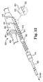
図15−17Bは、本明細書の開示の実施形態による、刺激リード線600の生体的吸収性(bio-absorbable)電極部601を備える刺激システムを概略的に示す。電極部600の配置前に、場所探知ツール(例えば図3に示される場所探知ツール200)若しくは他のツールによって、舌下神経上における1つ以上の最適な刺激場所が特定されている。1つ以上の外科的ナビゲーション技術を利用して、(1)場所探知ツールを用いて最適な刺激場所を特定し、(2)その最適な刺激場所に電極部を配置する。
FIGS. 15-17B schematically illustrate a stimulation system comprising a
図15に示されるように刺激リード線600は、カフ602および電極610を有する電極部601と、ワイヤ612と、アンカ614と、刺激リード線600の非生体的吸収性部分620とを備える。一実施形態では、カフ602は略伸長チューブ状部材を備え、略円筒形の形状を有する略伸長チューブ状部材は、電極610を保持するとともに、開放可能な固定状態にて神経625を包むように構成されている。これにより電極610が、密接に神経625に接触するように維持される。ワイヤ612は各電極610からカフ602を通じて基端方向にそれぞれ延びて、アンカ614や非生体的吸収性部分620よりも遠くまで延びるような長さを有することにより、IPG55(図1)と電気的に接続する。
As shown in FIG. 15, the
図17Aに示されるようにいくつかの実施形態では、各電極610は、導電性接触部616と、電気的絶縁カバー618とを備える。電気的絶縁カバー618は接触部616の上方部分639の上に延びており、図17Aに示される辺635、637を含む接触部616の4つ全ての辺を越えて広がる。電極610の基端部634において、張力緩和部材636はワイヤ611を経由してワイヤ612を接触部616に接続する。一実施形態によれば、電極610は、底部638がカフ602の内部表面にて露出された状態にてカフ602内に組み込まれる。いくつかの実施形態では、各電極610の長手方向軸がカフ602の長手方向軸に対して略垂直となるように電極610が配置され、各電極610はカフ602の長さ方向に沿って互いに間隔が空けられている。
In some embodiments, as shown in FIG. 17A, each
一態様によれば、カフ602が生体的吸収性材料で形成されていることにより、電極部601の移植後数週間が経過するとカフ602は体内に吸収される。これにより、電極610を神経625に対して所望の位置に置くことができる。カフ602が吸収されるのと同時に、ワイヤ612および電極610およびその周囲がカフ602の吸収から露出されることによりそこで組織成長が生じる。いくつかの実施形態では、ワイヤ612に(図15の拡大図にて示される)複数のコイル部613が配置されることにより、各コイル部における組織成長が分離したアンカとして機能するように、ワイヤ612およびその周囲における線維性組織成長がさらに誘発される。カフ602(および他のあらゆる生体的吸収性構成要素)の吸収プロセスが完了した後、線維性組織成長は、電極610の位置を所望の刺激場所における間隔の空けられた関係に維持し、電極610の位置をさらに維持するようにワイヤ612を固定する固定機構として機能するには十分なものとなる。その結果となる配置は図16および17Bに示される。図17Bの断面図において、線維性組織成長642は電極610およびワイヤ612を取り囲み、電極610を皮膚/筋肉部640の下の神経625上の所定位置に機械的に固定する。図17Bにさらに示されるように、絶縁性カバー618は各電極610を組織成長642から保護する。一態様によれば、絶縁性カバー618は各電極610の上方部分および横の部分を覆うが、各電極610の底部は神経625に対して露出したままである。いくつかの実施形態では、絶縁性カバー618の外部表面は線維性組織成長を誘発するように構成されたコーティングを有する。
According to one aspect, since the
一態様によれば、生体的吸収性カフを採用し、組織成長を誘発して電極610を固定することにより、このシステムが移植場所において及ぼす長期的な影響は最小限である。特に、移植されたカフのない電極610のセットは、従来のカフのように比較的大きなサイズでないため患者にとって快適である。このカフのない配置によれば、(従来のカフ電極システムと比較して)目標神経に対する不測の機械的影響を誘発する可能性が低い。このような機械的影響は神経機能および快適性に影響しうる。
According to one aspect, employing a bioabsorbable cuff to induce tissue growth and secure the
いくつかの実施形態では、アンカ614も生体的吸収性材料で形成されており、時間が経つと体内に吸収される。したがって、この領域において組織成長が生じると予想され、これによりワイヤ612が所定位置にさらに固定される。
In some embodiments, the
しかしながら、図15−16に示されるようにいくつかの実施形態では、刺激リード線600は、分離したワイヤ612をグループで維持するように構成された非吸収性留め具622を備える。一態様によれば、留め具622により、IPG55(図1)に延びる常設されたリード線部分620へ分離したワイヤ612を規則正しく移動させることが確保される。別の態様によれば、留め具622も張力緩和を提供し、目標神経上におけるワイヤ612の不測の引っ張りを防止する。しかしながら他の実施形態では、この留め具622は省略され、若しくは生体的吸収性材料で形成される。
However, in some embodiments as shown in FIGS. 15-16, the
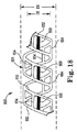
図18−21は、本明細書の開示の実施形態による、刺激リード線の生体的吸収性電極部650を概略的に示す。電極部650を配置する前に、場所探知ツール(例えば場所探知ツール200)若しくは他のツールによって、舌下神経上における1つ以上の最適な刺激場所が特定されている。1つ以上の外科的ナビゲーション技術を利用して、(1)場所探知ツールを用いて最適な刺激場所を特定し、(2)その最適な刺激場所に電極部を配置する。最終的に、電極部650の電極660はワイヤおよびリード線本体によってIPG55(図1)に電気的に接続されると予想され、この一般的な配置は、説明をわかりやすくするために図18−21では省略されている。
18-21 schematically illustrate a
図18−19は刺激リード線の電極部650の平面図であり、図18−19において電極部650は概ね柔軟なコイル部材651および電極660を備える。一般論として、コイル部材651は神経663の周囲を包み、電極660を神経663と密接に接触するように維持するステントのような絶縁性部材を形成する。しかしながら、血管の壁から外側に広げられることにより血管内に配置される従来の心臓血管のステントとは異なり、コイル部材651は、自己サイジング(self-sizing)の関係にて神経663の外部表面の周りを包むように構成されており、所望位置に配置されたときに放射状に広がるようには構成されていない。
18-19 is a plan view of the
いくつかの実施形態では、コイル部材651は、略らせん形の形状を形成し、間隔の空けられた1組のレール652を備え、1組のレール652は、レール652の間に延びてレール652を相互に接続する多数の支柱654を有する。一実施形態では、レール652および支柱654は非導電性の材料で形成される。一態様によれば図18−19に示されるように、電極660は、支柱654と同じような方法で1組のレール652の間に延びるように大きさおよび形状が決められている。一実施形態では、電極660はコイル部材651の長手方向軸と略一列に並ぶ。しかしながら、らせん形のコイル部材を形成するために支柱について多数の変形例や配列を用いることができるので、コイル部材651は、図18−19に示されるレール652および支柱654の配列に厳格に制限されない。
In some embodiments, the
図18に示される配置前の状態のように、コイル部材651は、目標神経663(図19も参照)の直径(D5)よりも実質的に小さい内径(D6)を有する。したがって、コイル部材651が直径の大きい神経663の周りに配置されると、コイル部材651は、図19に示されるようにコイル部材651の内径が目標神経663の直径に実質的に合致するように自己サイジングにより神経663の周りを包む。図19に示されるコイル部材651および神経663の間のあらゆる間隔に関する限り、これらの間隔は、コイル部材651の構成要素を神経663と離して明確に表し、説明を分かりやすくするためのものである。
As in the state before placement shown in FIG. 18, the
いくつかの実施形態では、コイル部材651はレール652および支柱654に組織成長を引き付け、組織成長、レール652、および支柱654の組み合わせによって、電極660と神経663との密接な接触を維持するための固定機構として機能する。
In some embodiments, the
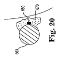
図20−21に示されるようにいくつか他の実施形態では、コイル部材651が生体的吸収性材料を形成していることにより、レール652および支柱654の吸収が生じた後も電極660は神経663に密接に接触したままであり、さらに電極660上およびその周囲の組織成長670は、電極660を神経663に対して所定位置に保持する。コイル部材651の各種構成要素(支柱およびレール)がコイル部材651の構造に概ね合致するパターンの線維性組織成長を誘発するように構成される格子若しくは枠を形成することにより、誘発された組織成長は、電極660を神経663に対して所定位置に保持する機械的に有利な枠を形成する。一態様によれば、線維性成長のこの枠は生体的カフを形成し、生体的カフにおいては体内に生成された組織が、電極610を神経に対して所定位置に維持するカフを形成する。
In some other embodiments, as shown in FIGS. 20-21, the
組織成長は、電極660からIPG55(図1)に向かって基端方向に向かって延びるワイヤ(図示せず)およびその周囲にて発生すると予想される。さらに前述の実施形態と同様に、電極660の外側部分(神経663に接触しない部分)は、電極660の接触部分と周囲の組織との間のバリアとして機能する絶縁性カバーを備えると予想される。
Tissue growth is expected to occur on and around a wire (not shown) extending proximally from
さらに一実施形態では、各電極660はワイヤのアレイのうちの1つにそれぞれ接続され、各ワイヤは、IPG55(図1)と電気的に接続するように構成された刺激リード線本体に延びてこれに接続する。一実施形態ではワイヤのアレイは、図15−16との関連で既に述べたワイヤ612のアレイと実質的に同じ機能および属性を含んでいる。
Further, in one embodiment, each
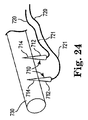
図22−24は、本明細書の開示の実施形態による刺激リード線の電極部700を概略的に示す。電極部700を配置する前に、場所探知ツール(例えば場所探知ツール200)若しくは他のツールによって、舌下神経上における1つ以上の最適な潜在的刺激場所が特定されている。1つ以上の外科的ナビゲーション技術を利用して、(1)場所探知ツールを用いて最適な刺激場所を特定し、(2)その最適な刺激場所に電極部を配置する。
22-24 schematically illustrate an
図22−23に示されるように、電極部700はキャリア702を備え、キャリア702は、キャリア702の長さ方向に沿って互いに間隔の空けられた概ねスパイク形状の電極710を支持する。キャリア702は先端704と基端706とを有する一方で、各電極710は露出した先端714と絶縁性にカバーされた土台部分712とを有する導電性部材を形成する。2つの電極710が示されているが、他の実施形態ではキャリア702は2以上の電極710を支持する。一実施形態では、キャリア702は第1の面および(第1の面の反対側にある)第2の面を有する略平坦な部材を備え、電極710は略平坦な部材の第1の面から概ね外側に延びる。
As shown in FIGS. 22-23, the
別態様によれば、各電極710において別々のワイヤ720が(図23の破線で示されるように)キャリア704の中を延びて、各電極710の土台部分712に電気的に接続される。さらに、電極710は当業者に知られる極細ワイヤで形成されており、図22−24では厳格に説明する目的で電極710が誇張および拡大されて示されている。
According to another aspect,
電極部700がいったん所望の刺激場所に運搬されると、各電極710の先端714を神経730内に挿入するための圧力が付与される。各電極710を形成する極細ワイヤの寸法が小さいことにより、神経の組織が電極710を効果的に捕獲し、電極710はこの位置に維持される。この配置によれば、神経730に対する電極の密接な接触が確保され、結果的に神経730に効果的な刺激を与えることができる。
Once the
いくつかの実施形態では、電極部700がいったん所定位置に固定されると、電極部700はキャリア702および針710の土台部分712の周りに組織成長(図示せず)を引き付ける。このとき、組織成長、キャリア702、および土台部分712の組み合わせは、電極の先端714を神経730に対する貫通(すなわち挿入)による係合状態にて維持する固定機構として機能する。
In some embodiments, once the
いくつか他の実施形態では、キャリア702が生体的吸収性材料を形成することにより、キャリア702は時間がたつと吸収され、図24に示されるように電極710およびワイヤ部分721、720は神経730において所定位置に置かれる。キャリア702の吸収が発生すると、電極710の土台部分712およびその周囲にて形成される組織成長が電極710を神経730に対する貫通による係合状態にて保持するため、電極710は、神経730に対する挿入による係合状態にて保持される。同様の組織成長が、電極660からIPG55(図1)へ基端方向に延びるワイヤ部分721、720およびその周囲にて発生すると予想される。
In some other embodiments,
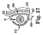
図25−32は、本明細書の開示の実施形態による、刺激システム800、およびシステム800の構成要素を移植する方法を概略的に示す。図25−27に示されるように、刺激システム800は、刺激リード線803の少なくとも1つの電極部801と、シールド804とを備える。電極部801を配置する前に、場所探知ツール(例えば、図1に示す場所探知ツール200)若しくは他のツールによって、舌下神経上における1つ以上の最適な潜在的刺激場所が特定されている。1つ以上の外科的ナビゲーション技術を利用して、(1)場所探知ツールを用いて最適な刺激場所を特定し、(2)その最適な刺激場所に電極部を配置する。
FIGS. 25-32 schematically illustrate a
図25に示されるように、刺激リード線803は、電極部801とリード線本体808とを備え、電極部801は、先端817および基端816の間を延びる略伸長キャリア本体と、電極ストリップ815とを備える。電極ストリップ815は、キャリア本体の長さ方向に沿って間隔の空けられた電極820のアレイ818を備える。リード線本体808は電極部801から基端方向に伸びて、IPG(図1の55若しくは図2の109)までの延長部でありIPGへ電気的な接続を行うように構成された基端リード線部分812とともにアンカ810を備える。
As shown in FIG. 25, the
少なくとも図26−27に示されるように、電極ストリップ815は、神経840の両側から外側に向かって神経840の直径にわたって伸びるのに十分かつ神経の直径よりも実質的に長い長さ(L2)を有する。一実施形態では、長さ(L2)は神経の直径の少なくとも2倍の長さである。別の実施形態では、長さ(L2)は神経の直径の少なくとも3倍の長さであり、予想される神経の直径を約3mmとして、電極部815は約9mmの長さを有する。図26−27に示されるように本実施形態によれば、電極ストリップ815の全長のうち約3mmは神経840に非常に近接する若しくは接触するものと予想され、一方で、電極ストリップ815の長さのうち約3mmは神経840の片側から外側に向かって延びるものと予想される。いくつかの実施形態では(後に図30−32に関連して詳細に説明されるように)、電極ストリップ815は約3mmの幅(W4)を有するため、低侵襲移植方法を促進する。それに比べて、従来のカフ電極は一般的に約9mmの幅を有する場合がある。
As shown at least in FIGS. 26-27, the
図26に示されるように、使用中において、電極部801は舌下神経840沿いの所望の刺激場所へ運搬され、電極ストリップ815は、(所望の刺激場所の領域における)神経840の長手方向軸(線A)に対して略垂直方向を向く。図27の断面図に示されるように一実施形態によれば、電極部801は、電極ストリップ815の電極820が神経840に面して神経840に対して刺激信号を付与するようにして配置される。さらに、いくつかの実施形態では、各電極820は、前述の実施形態と実質的に同じ方法によりIPG55(図1)を利用して互いに独立してプログラム可能若しくは制御可能であるため、電極ストリップ815の位置を変えることなく刺激信号の制御および調整を行うことができる。さらに、絶縁性シールド804を神経840と皮膚830と(その下にある筋肉832と)の間に配置することにより、皮膚830への刺激信号の付与を防止しつつ、神経840に対して刺激信号を付与することを可能とする。
As shown in FIG. 26, in use, the
図27の断面図に示されるように、このような配置によれば、神経840は電極ストリップ815と絶縁性シールド804との間に挟まれて、電極部801は、電極ストリップ815の少なくとも一部が神経840の外側表面に近接若しく密接して延びるように配置される。しかしながら、このようなサンドイッチ型の配置によれば、電極ストリップ815およびシールド804のそれぞれが独立して周囲組織に固定され、電極ストリップ815もシールド804も神経840には固定されない。例えば一実施形態によれば、電極ストリップ815は周囲組織に対し、アンカ(図26のx878およびx879)によって電極ストリップ815の各端部にて神経840とは独立して固定される。この配置によれば、電極ストリップ815およびシールド804の両方に対して略垂直方向を向いているので、神経840は電極ストリップ815およびシールド804の両方に対して短手方向(矢印M)へ移動することが可能となる。したがって、患者の首が多くの異なる位置を通じて幅広く移動するときに神経840のずれが許容される。
As shown in the cross-sectional view of FIG. 27, according to such an arrangement, the
このことを考慮して、神経の短手方向の動き(矢印M)があっても電極ストリップ815およびシールド804の両方とも動かず、神経840が動いてもサンドイッチ型の配置が維持される。したがって、電極ストリップ815は、神経840の直径よりも実質的に長い長さ(L2)を有するので、神経840が(自然な移動制限範囲内において)短手方向のいかなる位置にあっても神経840に対する効果的な刺激信号を付与できる位置にある。同様に、シールド804は、神経840の直径よりも実質的に長くかつ電極ストリップ815の長さ(L2)よりも実質的に長い長さ(L3)を有するので、常に、皮膚830(およびその下にある知覚神経)への刺激信号の付与を遮断する位置に配置される。一実施形態では、シールド804は、電極820によって生み出される皮膚表面に向かう電場の領域よりも、実質的に大きな領域を形成している。
In view of this, both the
電極部801は(刺激場所における)神経840の長手方向軸に対して略垂直に延びるが、いくつかの実施形態では、リード線本体808はIPG55(図1)への経路をたどるように神経840の長手方向軸に対して略並行に延びる。前述のように、リード線本体808は、リード線本体808(および電極部801)を神経840の近傍にある解剖学的構造および組織に安全に固定することを可能にするアンカ810を備える。アンカ810より、リード線本体808の基端部812は経皮的トンネルを経由してIPG55(図1)へさらに延びている。
Although the
いくつかの実施形態では、その他のカフのない電極構造においても、電極ストリップ(例えば電極ストリップ815)が神経840に対して垂直な方向を向くように利用されている。例えば、図11−14Cに関連する実施形態を配置することにより、カフによって神経840の周囲を包むことなく一連の電極582が目標神経の長手方向軸を横断して並ぶように、電極部565を神経に対して略垂直な方向に配置することも可能である。神経を全断面(若しくは直径)にわたって捕獲するために、電極部565における電極接触の数は適宜調整される。
In some embodiments, even in other cuff-free electrode structures, the electrode strip (eg, electrode strip 815) is utilized so that it is oriented perpendicular to the
図25−29をさらに参照するといくつかの実施形態では、電極部801は1つ以上の固定機構を備える。図28は、一連の電極接触820、先端852、および基端854を備える電極部850の上面図である。先端852において、1つ以上のループ(若しくはその他固定要素)860が設けられていることにより、先端852を神経840の近傍にある周囲組織へ縫合若しくは留めることができる。同様に、基端854において、1つ以上のループ(若しくはその他固定要素)870、872が設けられていることにより、基端854を神経840の近傍にある周囲組織へ縫合若しくは留めることができる。このようにして、神経840自体に固定することなく、および/又は神経840を包むことなく、電極ストリップ850を神経840に近接する安定した位置へ(神経とは独立して)固定することができる。
With further reference to FIGS. 25-29, in some embodiments, the
図29の断面図に概略的に示されるようにいくつか他の実施形態では、電極ストリップ815およびシールド804は互いに固定される。これらの実施形態では、神経840に対する電極ストリップ815およびシールド804のサンドイッチ型の配置が維持されることにより、電極ストリップ815を経由した神経840への電気的刺激を可能にしつつ、シールド804によって皮膚830を保護しながら、神経840による短手方向(矢印M)の移動が可能になる。特に、固定機構870は第1の構成要素872と第2の構成要素874とを備え、各構成要素872、874は電極ストリップ815およびシールド804の間を延びるように大きさが決められている。これに制限されない一態様によれば、神経840の側面に(各ストリップおよびシールドの第1の端部に接続される)第1の構成要素872が設けられ、神経840の反対側の側面に(各ストリップおよびシールドの第2の端部に接続される)第2の構成要素874が設けられていることにより、固定機構870が短手方向の境界若しくはバリアとして機能する。これにより、神経840による短手方向の移動を可能にしながら、神経840が電極ストリップ815およびシールド804の間に位置したままであることが確保される。他の実施形態では、各電極ストリップ815およびシールド804における一方の端部のみが互いに固定され、もう一方の端部は開放されている。
In some other embodiments, as schematically illustrated in the cross-sectional view of FIG. 29, the
一実施形態では、固定機構870の第1の構成要素872は、電極ストリップ815の先端817およびシールド804の先端805に接続可能なバックル−ベルト機構を備える。同様に、第2の構成要素874は、電極ストリップ815の基端816およびシールド804の基端807に接続可能なバックル−ベルト機構を備える。
In one embodiment, the
図30−32に概略的に示されるようにいくつかの実施形態では、シールド804および電極ストリップ815の組合せは、低侵襲移植方法により経皮的に運搬される。特に、電極ストリップ815は幅が非常に狭いので(例えば、図25−27で示される幅は3mm)、図31に示されるように、皮膚830(およびその下にある組織/筋肉832)のうち下部の神経840の対向する側面上に2つの小さな切開880、882を形成することにより手術が始まる。少なくとも1つの切開880、882の幅(W6)は、電極ストリップ815の幅(図25に示すW4)に概ね相当する。図30に示されるように、電極接触820が皮膚830に面しながら神経840に密接するように電極ストリップ815が神経840の下部に配置されるまで、電極ストリップ815は、鉗子(図示せず)を用いて(矢印EおよびRで示されるように)切開880および切開882を通じて操作される。次に、シールド804は、切開880および/又は切開882を含む同様の技術を用いて神経840および皮膚830の間の位置に案内される。必要に応じて、大きな幅(W5)を有するシールド804が各切開を通じて案内されるように、各切開880、882の幅をわずかに広げることもできる。このような低侵襲移植法によれば、神経840の上若しくは近傍にある皮膚および組織の崩壊を最小限にしながら、神経840に対する電極ストリップ815およびシールド804のサンドイッチ型の配置を実現することができる。したがって、電極ストリップ815およびシールド804の組み合わせは、カフのない電極として機能することにより自然状態の神経に対する影響を最小限にする刺激システムを提供するとともに、これらの要素を低侵襲にて移植する方法を可能にする。
In some embodiments, as schematically illustrated in FIGS. 30-32, the combination of
図1−14に関連していくつかの異なる実施形態について記述したが、これらの実施形態では、IPG55は肺の領域に移植され、(IPG55から延びる)センサ電極および刺激電極は、それぞれが呼吸パターンを検知して刺激信号を付与するように経皮的に運搬される。加えて、図15−32に関連して刺激電極アレイ(およびそれに関連する固定機構)のいくつかの実施形態について記述している。さらに、これらの実施形態のうちいくつかの実施形態では、リード線が体の両側(右側と左側)に経皮的に配置され、左および/又は右の舌下神経(若しくは他の目標神経)において(同時若しくは交互の)双対的な刺激が生じる。これらの様々な実施形態を考慮すると、これらの実施形態に共通して、体内の上部気道の近傍に少なくとも2つの電極が間隔を空けて配置され、気道開通性(例えば、上部気道の開および/又は閉)を示すために間隔の空けられた2つの電極間におけるインピーダンスが測定可能ないくつかの構成が設けられている。いくつかの構成によれば、間隔の空けられた電極は両方とも刺激電極であり、他の構成によれば、間隔の空けられた電極は1つの刺激電極と1つの呼吸センサ電極とを備える。さらに他の構成によれば、(気道開通性を示すインピーダンスを測定するための)間隔の空けられた2つの電極は、少なくとも1つの刺激電極および呼吸センサ電極を有する1つの電極と、IPG55のケース若しくは筐体の電気的導電性部分によって形成される電極を有するもう1つ別の電極とを備える。
While several different embodiments have been described in connection with FIGS. 1-14, in these embodiments, the
さらにいくつかの実施形態では、各電極部は、一対のインピーダンスセンサ電極の一部として機能するとともに呼吸センサ機能若しくは刺激機能を持つというように、2つの機能を有する。一方で他の実施形態では、一対のインピーダンスセンサ電極のうち少なくとも1つの電極は、呼吸検知(例えば吸気)や刺激を行うものとしては機能せずに、専ら、気道開通性の程度を検知若しくは表示することを目的としてインピーダンスを検知するために用いられる。 Further, in some embodiments, each electrode portion has two functions, such as functioning as part of a pair of impedance sensor electrodes and having a respiratory sensor function or a stimulation function. On the other hand, in other embodiments, at least one of the pair of impedance sensor electrodes does not function as a device that performs respiratory detection (for example, inspiration) or stimulation, and exclusively detects or displays the degree of airway patency. It is used to detect impedance for the purpose of doing so.
(本明細書に記載されている)経皮的に運搬される電極部の少なくともいくつかの実施形態によれば、外科医が経皮的手法を用いて舌下神経の長さ方向に沿って刺激リード線の電極部の位置を変化させることができるため、最適な神経刺激場所の近傍に電極部を正確に配置することができる。さらに、このような正確な配置は、刺激リード線を配置するための解剖学的に破壊的な従来の切断手法とは異なり低侵襲な方法により実施される。本明細書の開示による方法およびシステムによれば、目標神経に対する電極部の位置を固定する前に、外科医は、(気道開通性を回復させるのに適した)1つ以上の特定の筋肉の収縮を引き起こす正しい最適刺激場所を特定することができる。 According to at least some embodiments of the percutaneously delivered electrode portion (described herein), the surgeon uses a percutaneous technique to stimulate along the length of the hypoglossal nerve. Since the position of the electrode portion of the lead wire can be changed, the electrode portion can be accurately arranged in the vicinity of the optimal nerve stimulation location. Furthermore, such precise placement is performed in a minimally invasive manner, unlike conventional anatomically disruptive cutting techniques for placing stimulation leads. In accordance with the methods and systems according to the disclosure herein, prior to fixing the position of the electrode portion relative to the target nerve, the surgeon can contract one or more specific muscles (suitable to restore airway patency). It is possible to identify the correct optimal stimulation location that causes
本明細書に開示された実施形態は閉塞性睡眠時無呼吸と診断された患者に治療上の解決方法を提供するために移植可能システムを提供する。本システムは吸気時に舌下神経を刺激して、それにより睡眠中の上気道の閉塞を防ぐように設計されている。 The embodiments disclosed herein provide an implantable system to provide a therapeutic solution for patients diagnosed with obstructive sleep apnea. The system is designed to stimulate the hypoglossal nerve during inspiration, thereby preventing obstruction of the upper airway during sleep.
少なくとも1つの例示的実施形態が、上記の詳細な説明において提示されているが、変形が存在することを理解すべきである。例示的実施形態は、あくまで実施例に過ぎず、本明細書の開示の範囲、適用性、または構成をいかなる方法によっても限定するものではないことを理解すべきである。むしろ、上記の詳細な説明は例示的実施形態を実現するために便利なロード・マップを当業者に提供するであろう。添付クレームおよびそれらの法的な均等物に記載の本明細書の開示の範囲を逸脱することなく、要素の機能および配置においてさまざまな変更を行うことができることを理解すべきである。 While at least one exemplary embodiment has been presented in the foregoing detailed description, it should be appreciated that variations exist. It should be understood that the exemplary embodiments are merely examples, and are not intended to limit the scope, applicability, or configuration of the disclosure herein in any way. Rather, the above detailed description will provide those skilled in the art with a convenient road map for implementing an exemplary embodiment. It should be understood that various changes can be made in the function and arrangement of elements without departing from the scope of the disclosure herein as set forth in the appended claims and their legal equivalents.
Claims (55)
案内機構の先端部を経皮的に挿入し、案内機構の基端部を皮膚表面の外側に維持しながら案内機構の先端部を目標神経の刺激場所の近傍に配置する工程と、
案内機構の基端部に対して刺激リード線を開放可能に係合させ、刺激リード線の先端部が目標刺激場所に位置するまで刺激リード線を経皮的に挿入するために案内機構を経由して刺激リード線をスライド可能に前進させる工程と、を含む方法。 A method of implanting stimulation leads to treat sleep related breathing disorders,
Inserting the distal end portion of the guide mechanism percutaneously and arranging the distal end portion of the guide mechanism in the vicinity of the stimulation location of the target nerve while maintaining the proximal end portion of the guide mechanism outside the skin surface;
The stimulating lead is releasably engaged with the proximal end of the guiding mechanism, and the guiding lead is inserted through the guiding mechanism until the leading end of the stimulating lead is positioned at the target stimulation location. And slidably advancing the stimulation lead.
固定機構を位置させる工程は、刺激リード線の先端部の第2の面上に固定機構を位置させる工程を含む、請求項4に記載の方法。 The stimulation lead has a first surface and a second surface opposite the first surface;
The method of claim 4, wherein positioning the fixation mechanism comprises positioning the fixation mechanism on a second surface of the tip of the stimulation lead.
神経と皮膚表面との間に置かれる絶縁性要素を有するように、刺激リード線の先端部の第2の面を配列させる工程と、を含む、請求項5に記載の方法。 Aligning the first surface of the tip of the stimulation lead to have at least one stimulation electrode configured to releasably contact a nerve at a target stimulation location;
Aligning the second surface of the tip of the stimulation lead with an insulative element placed between the nerve and the skin surface.
案内機構を経由して刺激リード線をスライド可能に前進させる工程にはカニューレを通じて刺激リード線をスライド可能に前進させる工程が含まれ、
カニューレを通じた刺激リード線の先端部の前進中において、先端部がカニューレの内部表面に対して係合することにより各部材を第1の保存位置に維持する工程と、
目標刺激場所からカニューレを離脱させた後、刺激リード線の各部材を第1の保存位置から第2の配置位置へ開放する工程と、を含む方法。 8. The method of claim 7, comprising providing at least a portion of the guide mechanism as a cannula,
Slidably advancing the stimulation lead via the guide mechanism includes slidably advancing the stimulation lead through the cannula,
Maintaining each member in a first storage position by advancing the tip of the stimulation lead through the cannula with the tip engaging the inner surface of the cannula;
Releasing each member of the stimulation lead from the first storage position to the second deployed position after removing the cannula from the target stimulation location.
案内機構の先端部を経皮的に挿入する工程は、概ね湾曲した形状の柔軟性先端部を有することにより、配置位置のときにはカニューレの端部がカニューレの基端部の長手方向軸に対して概ね鈍角となる方向を向き、挿入位置のときにはカニューレの基端部の長手方向軸に概ね平行となる方向を向くように柔軟性先端部が構成可能であるカニューレを準備する工程をさらに含む、請求項1に記載の方法。 The step of percutaneously inserting the distal end of the guide mechanism includes the step of providing at least a portion of the guide mechanism as a cannula, the step of slidably advancing the stimulation lead via the guide mechanism through the cannula. Including slidably moving the stimulation lead forward,
The step of percutaneously inserting the distal end of the guide mechanism includes having a generally curved flexible tip so that when in the deployed position, the end of the cannula is relative to the longitudinal axis of the proximal end of the cannula. And further comprising the step of providing a cannula in which the flexible tip is configurable to face in a generally obtuse angle and, when in the insertion position, in a direction generally parallel to the longitudinal axis of the proximal end of the cannula. Item 2. The method according to Item 1.
刺激リード線の先端部が目標刺激場所にくるまで、刺激リード線の先端部をカニューレの端部から外へスライド可能に前進させる工程と、
目標刺激場所に刺激リード線の先端部を維持しながらカニューレを離脱させる工程と、を含む請求項12に記載の方法。 After placing the tip of the stimulation lead at the target stimulation location, the step of making the flexible tip substantially curved,
Advancing the tip of the stimulation lead slidably out of the end of the cannula until the tip of the stimulation lead is at the target stimulation location;
13. The method of claim 12, further comprising the step of detaching the cannula while maintaining the tip of the stimulation lead at the target stimulation location.
第1の距離は、先端部が配置位置にあるときにカニューレの端部とカニューレの基端部の長手方向軸との距離である第2の距離と、最大で刺激リード線の電極部の長さに相当する第3の距離との合計に略等しい、請求項13に記載の方法。 Including placing the cannula entry point into the skin surface at a first distance from the target stimulation location, wherein the first distance is the end of the cannula and the proximal end of the cannula when the tip is in the deployed position. 14. The method of claim 13, wherein the second distance, which is the distance to the longitudinal axis of the first, and approximately the sum of the third distance corresponding to the length of the electrode portion of the stimulation lead at most.
案内機構を経由して刺激リード線をスライド可能に前進させる工程には、カニューレを通じて刺激リード線をスライド可能に前進させる工程が含まれ、刺激リード線の先端部が目標刺激場所にきてカニューレの基端部に対して概ね鈍角となる方向を向くまで、刺激リード線の先端部が開口の端部から外へ延び、
案内機構の先端部を経皮的に挿入する工程は、目標刺激場所に刺激リード線の先端部を維持しながらカニューレを離脱させる工程をさらに含む、請求項1に記載の方法。 The step of percutaneously inserting the tip of the guide mechanism includes providing a generally rigid and straight tip having an opening oriented generally perpendicular to the longitudinal axis of the cannula and providing at least a portion of the guide mechanism as a cannula. Preparing a cannula to have a section,
The step of slidably advancing the stimulation lead via the guide mechanism includes the step of slidably advancing the stimulation lead through the cannula, with the tip of the stimulation lead coming to the target stimulation location and the cannula of the cannula. The distal end of the stimulation lead extends out from the end of the opening until it faces a direction that is generally obtuse with respect to the proximal end,
The method of claim 1, wherein the step of percutaneously inserting the distal end of the guide mechanism further comprises detaching the cannula while maintaining the distal end of the stimulation lead at the target stimulation location.
目標刺激場所を含む複数のテスト刺激場所にテスト針を経皮的に挿入する工程と、
各テスト刺激場所に刺激信号を付与することにより、複数のテスト刺激場所の中から目標刺激場所を決定する工程と、
刺激信号の付与中に、舌の突出若しくは引っ込みの発生、上部気道の断面積の変化、非目標筋肉における反応欠如、舌筋若しくは喉頭筋のけいれん、又は目標筋肉における最大の筋電図検査反応、のうち少なくとも1つを監視する工程と、を含む、請求項1に記載の方法。 The process of inserting the test needle percutaneously is
Inserting a test needle percutaneously into a plurality of test stimulation locations including the target stimulation location;
Determining a target stimulus location from a plurality of test stimulus locations by applying a stimulus signal to each test stimulus location;
During the application of a stimulus signal, the occurrence of tongue protrusion or retraction, changes in the cross-sectional area of the upper airway, lack of response in non-target muscles, lingual or laryngeal muscle spasms, or maximum electromyographic response in target muscles; And monitoring at least one of the methods.
各刺激パラメータは、振幅パラメータ、周波数パラメータ、パルス幅パラメータ、極性パラメータ、および継続時間パラメータのうちの少なくとも1つを含む、請求項19に記載の方法。 Determining the target stimulation location includes changing the array of stimulation parameters at each test stimulation location;
20. The method of claim 19, wherein each stimulus parameter includes at least one of an amplitude parameter, a frequency parameter, a pulse width parameter, a polarity parameter, and a duration parameter.
先端部と基端部とを有するテスト針であって、基端部は開放可能に基端部に固定されたハンドルを備え、ハンドルは皮膚表面の外部に残るように大きさが決められ、針は神経に対して経皮的にアクセスするように構成された長さを有する、テスト針と、
先端部および基端部を有する概ねチューブ状の部材を形成し、テスト針を越えてスライドして前進可能に構成されたカニューレと、
電極アレイを形成する第1の面と第1の面の反対側にある第2の面とを有する先端部を備える刺激リード線であって、第2の面は、選択的に配置可能な固定機構と、カニューレの中をスライド可能に前進するように構成されてカニューレの長さよりも長い長さを有する刺激リード線とを形成する、刺激リード線と、を備えるシステム。 A transcutaneous access system for implanting stimulation leads to treat sleep related breathing disorders,
A test needle having a distal end and a proximal end, the proximal end having a handle releasably secured to the proximal end, the handle being sized to remain outside the skin surface, the needle A test needle having a length configured for percutaneous access to the nerve;
A cannula configured to form a generally tubular member having a distal end and a proximal end, and to be slidable and advanced over the test needle;
A stimulation lead comprising a tip having a first surface forming an electrode array and a second surface opposite the first surface, wherein the second surface is a selectively positionable fixation And a stimulation lead configured to slidably advance within the cannula to form a stimulation lead having a length greater than the length of the cannula.
テスト針の長さ方向に沿って間隔の空けられた一連の目盛りマーキングを備え、テスト針の挿入深さを経皮的に測定するように配置されたテスト針の中間部分のうち、
少なくとも1つを備える、請求項22に記載のシステム。 An intermediate portion of the cannula arranged with a series of tick markings spaced along the length of the cannula and arranged to measure the insertion depth of the cannula percutaneously;
Of the middle part of the test needle, which is arranged to measure the insertion depth of the test needle percutaneously, with a series of scale markings spaced along the length of the test needle,
24. The system of claim 22, comprising at least one.
カニューレに対して開放可能に係合されるとともにカニューレ内に搭載された位置にある補強剤を備え、補強剤は、柔軟な先端部をカニューレの基端部の長手方向軸に略平行な方向に向け、離脱位置にあるときは柔軟な先端部を概ねその湾曲した形状となるようにする、システム。 23. The system of claim 22, wherein the tip of the cannula is flexible and has a generally curved shape that directs the tip of the cannula in a direction generally perpendicular to the longitudinal axis of the proximal end of the cannula.
A reinforcing agent releasably engaged with the cannula and mounted in the cannula, the reinforcing agent having a flexible distal end in a direction substantially parallel to the longitudinal axis of the proximal end of the cannula A system that allows the flexible tip to be generally in its curved shape when in a directed or detached position.
ハンドルと、
ハンドルから延びて、神経に対する経皮的アクセスを提供するように構成された長さを有するバレルと、
バレルによって支持され、電極本体を神経に対して固定するための少なくとも1つの選択的に配置可能な返しを備える係合機構と、を備え、
神経に対する電極本体の固定は、少なくとも1つの返しによる係合を神経の近傍にある組織の中へ貫通させることにより行われ、
電極本体は、目標神経の近傍へ配置するための経皮的挿入を行えるように大きさおよび形状が決められている、機器。 An electrode implantation device for establishing percutaneous access to a nerve,
A handle,
A barrel extending from the handle and having a length configured to provide percutaneous access to the nerve;
An engagement mechanism supported by the barrel and comprising at least one selectively displaceable barb for securing the electrode body to the nerve;
Fixing the electrode body to the nerve is accomplished by penetrating at least one barb engagement into tissue in the vicinity of the nerve,
The electrode body is sized and shaped to allow percutaneous insertion for placement near the target nerve.
係合機構は、バレルの中を通ってバレル内で長手方向に移動可能な少なくとも1つのロッドを備え、
少なくとも1つの返しは、少なくとも1つのロッドの先端に開放可能に結合される、請求項28に記載の機器。 The barrel comprises a generally hollow elongated tubular member;
The engagement mechanism comprises at least one rod movable longitudinally within the barrel through the barrel;
30. The device of claim 28, wherein the at least one barb is releasably coupled to the tip of the at least one rod.
開放トリガは、神経の近傍にある組織の中に貫通するよう少なくとも1つの返しを整列させるように、少なくとも1つのロッドをバレルの先端から外に向かって前方へ移動させるように構成されている、請求項29に記載の機器。 The handle includes an opening trigger coupled to the proximal end of the rod via the barrel,
The open trigger is configured to move the at least one rod forward from the tip of the barrel outward to align the at least one barb to penetrate into tissue in the vicinity of the nerve. 30. The device of claim 29.
少なくとも1つの返しはロッドの先端から開放されても電極に接続されたままである、請求項32に記載の機器。 Comprising at least one suture member connecting the electrode body to the at least one barb and being disposed therebetween,
35. The device of claim 32, wherein at least one barb remains connected to the electrode when released from the tip of the rod.
第1のアレイは電極本体の第1の面の部分上に配置され、第2のアレイは電極本体の第2の面の部分上に配置され、
第1のアレイおよび第2のアレイは、神経の幅よりも大きい幅をもって短手方向に間隔が空けられている、請求項32に記載の機器。 The at least one return comprises a first return array and a second return array;
The first array is disposed on a portion of the first surface of the electrode body, the second array is disposed on a portion of the second surface of the electrode body;
33. The device of claim 32, wherein the first array and the second array are spaced in the transversal direction with a width greater than the width of the nerve.
神経のまわりに開放可能に適合するように構成され、生体的吸収性材料で形成されたカフと、
カフ内にはめこまれた電極要素のアレイと、を備え、
各電極要素の長手方向軸はカフの長手方向軸に対して概ね垂直であり、各電極要素はカフの長さ方向に沿って互いに間隔が空けられており、
それぞれが各電極要素に接続されるとともにそこから延びるワイヤのアレイをさらに備え、
ワイヤのアレイは刺激リード線の本体から先端方向に延びており、
カフは目標神経の近傍に経皮的に挿入可能なように大きさおよび形状が決められている、電極システム。 An electrode system implantable percutaneously,
A cuff configured to releasably fit around a nerve and formed of a bioabsorbable material;
An array of electrode elements embedded in the cuff,
The longitudinal axis of each electrode element is generally perpendicular to the longitudinal axis of the cuff, and each electrode element is spaced from one another along the length of the cuff;
Further comprising an array of wires each connected to and extending from each electrode element;
An array of wires extends distally from the body of the stimulation lead,
An electrode system that is sized and shaped so that the cuff can be inserted percutaneously in the vicinity of the target nerve.
カフの生体的吸収性材料は少なくとも1つの絶縁性カバーと各電極要素の側面とを概ね取り囲む、請求項36に記載の電極システム。 Each electrode element includes a conductive portion having a bottom exposed at the inner surface of the cuff and a top opposite the bottom, and an insulating cover connected to and surrounding both the top and sides of the conductive portion With
38. The electrode system of claim 36, wherein the cuff bioabsorbable material generally surrounds at least one insulative cover and a side surface of each electrode element.
生態的吸収性材料で形成され、神経のまわりにて自己サイジングで崩壊することにより神経と結合するように構成された伸長ステントと、
ステントによって支持される電極要素のアレイと、を備え、
各電極要素は、チューブ状部材の長さ方向に沿って互いに間隔が空けられており、
それぞれが各電極要素に接続されるとともにそこから延びるワイヤのアレイをさらに備え、
ワイヤのアレイは刺激リード線の本体から先端方向に延びており、
伸長ステントは目標神経の近傍に経皮的に挿入可能なように大きさおよび形状が決められている、電極システム。 An electrode system implantable percutaneously,
An elongated stent formed of a bioabsorbable material and configured to bind to nerves by self-sizing around the nerves;
An array of electrode elements supported by a stent;
Each electrode element is spaced from each other along the length of the tubular member,
Further comprising an array of wires each connected to and extending from each electrode element;
An array of wires extends distally from the body of the stimulation lead,
An electrode system, wherein the elongated stent is sized and shaped to be inserted percutaneously in the vicinity of the target nerve.
生態的吸収性材料で形成された伸長キャリアと、
キャリアによって支持される電極スパイクのアレイと、を備え、
各電極スパイクは、キャリアの表面から概ね外側に向かって延びるとともにキャリアの長さ方向に沿って互いに間隔が空けられており、
それぞれが各電極スパイクに接続されるとともにそこから延びるワイヤのアレイをさらに備え、
ワイヤのアレイは刺激リード線の本体から先端方向に延びており、
伸長キャリアは目標神経の近傍に経皮的に挿入可能なように大きさおよび形状が決められている、電極システム。 An electrode system implantable percutaneously,
An elongated carrier formed of an ecologically absorbent material;
An array of electrode spikes supported by a carrier;
Each electrode spike extends generally outward from the surface of the carrier and is spaced from one another along the length of the carrier,
Further comprising an array of wires each connected to and extending from each electrode spike;
An array of wires extends distally from the body of the stimulation lead,
An electrode system, wherein the extension carrier is sized and shaped so that it can be inserted percutaneously in the vicinity of the target nerve.
電極要素によって生成される電場の領域よりも実質的に大きい領域を形成する絶縁性シールドと、
キャリアを絶縁性シールドに接続することにより、絶縁性シールドが刺激ユニットよりも皮膚表面の近くにある状態で刺激ユニットおよび絶縁性シールドを神経の反対側に配置する留め具機構と、を備え、
刺激ユニット、絶縁性シールド、および留め具機構のそれぞれは、目標神経の近傍に経皮的に挿入可能なように大きさおよび形状が決められている、経皮的電極システム。 An elongated carrier having a distal end, a proximal end, and a body extending between the distal end and the proximal end, and an array of electrode elements that are spaced along the length of the elongated carrier and configured to generate an electric field A stimulation lead that is electrically connected to each electrode element, and a stimulation unit
An insulative shield that forms a region substantially larger than the region of the electric field generated by the electrode element;
A fastening mechanism that places the stimulation unit and the insulation shield on the opposite side of the nerve with the insulation shield closer to the skin surface than the stimulation unit by connecting the carrier to the insulation shield;
The transcutaneous electrode system, wherein each of the stimulation unit, the insulating shield, and the fastener mechanism is sized and shaped for percutaneous insertion in the vicinity of the target nerve.
各ワイヤは、その他のワイヤやその他の電極要素とは独立して各電極要素へ電気的に接続される、請求項49に記載の電極システム。 The stimulation lead comprises a plurality of wires,
50. The electrode system of claim 49, wherein each wire is electrically connected to each electrode element independently of the other wires and other electrode elements.
神経とは反対側に、皮膚−筋肉層を通る1組の切開を経皮的に生成する工程と、
1つの切開の中に刺激ユニットを経皮的に挿入し、刺激ユニットを、刺激ユニットの電極アレイが神経および皮膚表面に面するように神経の裏側まで組織の中を前進させる工程と、
1つの切開の中に絶縁性シールドを経皮的に挿入し、絶縁性シールドを、神経と皮膚表面の間に位置するように刺激ユニットの電極アレイとは反対側の神経周囲の位置まで組織の中を前進させる工程と、を含む方法。 A method of implanting a stimulation electrode transcutaneously,
Creating a set of incisions percutaneously through the skin-muscle layer on the opposite side of the nerve;
Inserting the stimulation unit percutaneously into one incision and advancing the stimulation unit through the tissue to the back of the nerve so that the electrode array of the stimulation unit faces the nerve and skin surface;
An insulative shield is inserted percutaneously into one incision, and the insulative shield is placed between the nerve and the skin surface to a position around the nerve opposite to the stimulation unit electrode array. Advancing through the method.
Applications Claiming Priority (3)
| Application Number | Priority Date | Filing Date | Title |
|---|---|---|---|
| US16511009P | 2009-03-31 | 2009-03-31 | |
| US61/165,110 | 2009-03-31 | ||
| PCT/US2010/029253 WO2010117810A1 (en) | 2009-03-31 | 2010-03-30 | Percutaneous access for systems of treating sleep-related disordered breathing |
Publications (2)
| Publication Number | Publication Date |
|---|---|
| JP2012521864A true JP2012521864A (en) | 2012-09-20 |
| JP2012521864A5 JP2012521864A5 (en) | 2013-05-23 |
Family
ID=42168138
Family Applications (1)
| Application Number | Title | Priority Date | Filing Date |
|---|---|---|---|
| JP2012503627A Pending JP2012521864A (en) | 2009-03-31 | 2010-03-30 | Percutaneous access method in a system for treating sleep-related abnormal breathing |
Country Status (4)
| Country | Link |
|---|---|
| US (3) | US9486628B2 (en) |
| EP (1) | EP2416845B1 (en) |
| JP (1) | JP2012521864A (en) |
| WO (1) | WO2010117810A1 (en) |
Cited By (2)
| Publication number | Priority date | Publication date | Assignee | Title |
|---|---|---|---|---|
| WO2016200161A1 (en) * | 2015-06-11 | 2016-12-15 | 서울대학교산학협력단 | Nerve transplant device |
| KR101805063B1 (en) | 2015-04-16 | 2017-12-05 | 이승용 | Apparatus for skin tattoo |
Families Citing this family (98)
| Publication number | Priority date | Publication date | Assignee | Title |
|---|---|---|---|---|
| US20050149132A1 (en) | 2003-12-24 | 2005-07-07 | Imad Libbus | Automatic baroreflex modulation based on cardiac activity |
| US11679261B2 (en) | 2007-03-09 | 2023-06-20 | Mainstay Medical Limited | Systems and methods for enhancing function of spine stabilization muscles associated with a spine surgery intervention |
| US10925637B2 (en) | 2010-03-11 | 2021-02-23 | Mainstay Medical Limited | Methods of implanting electrode leads for use with implantable neuromuscular electrical stimulator |
| US11679262B2 (en) | 2007-03-09 | 2023-06-20 | Mainstay Medical Limited | Systems and methods for restoring muscle function to the lumbar spine |
| US8428728B2 (en) | 2007-03-09 | 2013-04-23 | Mainstay Medical Limited | Muscle stimulator |
| US9072897B2 (en) | 2007-03-09 | 2015-07-07 | Mainstay Medical Limited | Systems and methods for restoring muscle function to the lumbar spine |
| US11331488B2 (en) | 2007-03-09 | 2022-05-17 | Mainstay Medical Limited | Systems and methods for enhancing function of spine stabilization muscles associated with a spine surgery intervention |
| CN102112177A (en) | 2008-05-02 | 2011-06-29 | 梅德特龙尼克有限公司 | Self expanding electrode cuff |
| US8340785B2 (en) | 2008-05-02 | 2012-12-25 | Medtronic, Inc. | Self expanding electrode cuff |
| EP3181191B1 (en) | 2008-05-15 | 2020-03-11 | Inspire Medical Systems, Inc. | Apparatus for sensing respiratory pressure in an implantable stimulation system |
| EP2331201B1 (en) | 2008-10-01 | 2020-04-29 | Inspire Medical Systems, Inc. | System for treating sleep apnea transvenously |
| EP3184045B1 (en) | 2008-11-19 | 2023-12-06 | Inspire Medical Systems, Inc. | System treating sleep disordered breathing |
| US8515520B2 (en) | 2008-12-08 | 2013-08-20 | Medtronic Xomed, Inc. | Nerve electrode |
| WO2010117810A1 (en) | 2009-03-31 | 2010-10-14 | Inspire Medical Systems, Inc. | Percutaneous access for systems of treating sleep-related disordered breathing |
| US8577478B2 (en) | 2011-09-30 | 2013-11-05 | Nyxoah SA | Antenna providing variable communication with an implant |
| US11786725B2 (en) | 2012-06-13 | 2023-10-17 | Mainstay Medical Limited | Systems and methods for restoring muscle function to the lumbar spine and kits for implanting the same |
| US11684774B2 (en) | 2010-03-11 | 2023-06-27 | Mainstay Medical Limited | Electrical stimulator for treatment of back pain and methods of use |
| US9999763B2 (en) | 2012-06-13 | 2018-06-19 | Mainstay Medical Limited | Apparatus and methods for anchoring electrode leads adjacent to nervous tissue |
| US9950159B2 (en) | 2013-10-23 | 2018-04-24 | Mainstay Medical Limited | Systems and methods for restoring muscle function to the lumbar spine and kits for implanting the same |
| WO2011112773A2 (en) | 2010-03-11 | 2011-09-15 | Mainstay Medical, Inc. | Modular stimulator for treatment of back pain, implantable rf ablation system and methods of use |
| WO2011112843A1 (en) | 2010-03-12 | 2011-09-15 | Inspire Medical Systems, Inc. | Method and system for identifying a location for nerve stimulation |
| US8983572B2 (en) | 2010-10-29 | 2015-03-17 | Inspire Medical Systems, Inc. | System and method for patient selection in treating sleep disordered breathing |
| US20150039045A1 (en) | 2011-08-11 | 2015-02-05 | Inspire Medical Systems, Inc. | Method and system for applying stimulation in treating sleep disordered breathing |
| US8934992B2 (en) | 2011-09-01 | 2015-01-13 | Inspire Medical Systems, Inc. | Nerve cuff |
| US8983611B2 (en) | 2011-09-27 | 2015-03-17 | Cardiac Pacemakers, Inc. | Neural control of central sleep apnea |
| EP2788073B1 (en) | 2011-11-10 | 2018-03-21 | Medtronic Inc. | Introduction and anchoring tool for an implantable medical device element |
| SG11201407873RA (en) * | 2012-05-29 | 2014-12-30 | Autonomix Medical Inc | Endoscopic sympathectomy systems and methods |
| US9186501B2 (en) | 2012-06-13 | 2015-11-17 | Mainstay Medical Limited | Systems and methods for implanting electrode leads for use with implantable neuromuscular electrical stimulator |
| US10195419B2 (en) | 2012-06-13 | 2019-02-05 | Mainstay Medical Limited | Electrode leads for use with implantable neuromuscular electrical stimulator |
| EP2892436B1 (en) * | 2012-09-06 | 2019-03-13 | Norwegian University of Science and Technology (NTNU) | Treatment of headache by injection of neuroinhibitory substance to sphenopalatine ganglion or otic ganglion |
| WO2014089400A1 (en) | 2012-12-07 | 2014-06-12 | Medtronic, Inc. | Minimally invasive implantable neurostimulation system |
| US9308022B2 (en) | 2012-12-10 | 2016-04-12 | Nevro Corporation | Lead insertion devices and associated systems and methods |
| US9717923B2 (en) | 2013-05-06 | 2017-08-01 | Medtronic, Inc. | Implantable medical device system having implantable cardioverter-defibrillator (ICD) system and substernal leadless pacing device |
| US10556117B2 (en) | 2013-05-06 | 2020-02-11 | Medtronic, Inc. | Implantable cardioverter-defibrillator (ICD) system including substernal pacing lead |
| US10471267B2 (en) | 2013-05-06 | 2019-11-12 | Medtronic, Inc. | Implantable cardioverter-defibrillator (ICD) system including substernal lead |
| US9220913B2 (en) | 2013-05-06 | 2015-12-29 | Medtronics, Inc. | Multi-mode implantable medical device |
| US20140330287A1 (en) | 2013-05-06 | 2014-11-06 | Medtronic, Inc. | Devices and techniques for anchoring an implantable medical device |
| US10668270B2 (en) | 2013-05-06 | 2020-06-02 | Medtronic, Inc. | Substernal leadless electrical stimulation system |
| US10933230B2 (en) | 2013-05-06 | 2021-03-02 | Medtronic, Inc. | Systems and methods for implanting a medical electrical lead |
| US10434307B2 (en) | 2013-10-15 | 2019-10-08 | Medtronic, Inc. | Methods and devices for subcutaneous lead implantation |
| US10792490B2 (en) | 2013-11-12 | 2020-10-06 | Medtronic, Inc. | Open channel implant tools and implant techniques utilizing such tools |
| US10531893B2 (en) | 2013-11-12 | 2020-01-14 | Medtronic, Inc. | Extravascular implant tools with open sheath and implant techniques utilizing such tools |
| WO2015077283A1 (en) | 2013-11-19 | 2015-05-28 | The Cleveland Clinic Foundation | System for treating obstructive sleep apnea |
| WO2016020846A1 (en) * | 2014-08-06 | 2016-02-11 | Mainstay Medical Limited | Electrode leads for use with implantable neuromuscular electrical stimulator |
| EP3188793B1 (en) | 2014-09-04 | 2020-01-01 | Atacor Medical, Inc. | Receptacle for pacemaker lead |
| US10743960B2 (en) | 2014-09-04 | 2020-08-18 | AtaCor Medical, Inc. | Cardiac arrhythmia treatment devices and delivery |
| US9636505B2 (en) | 2014-11-24 | 2017-05-02 | AtaCor Medical, Inc. | Cardiac pacing sensing and control |
| US10328268B2 (en) | 2014-09-04 | 2019-06-25 | AtaCor Medical, Inc. | Cardiac pacing |
| US10471268B2 (en) | 2014-10-16 | 2019-11-12 | Mainstay Medical Limited | Systems and methods for monitoring muscle rehabilitation |
| US9636512B2 (en) | 2014-11-05 | 2017-05-02 | Medtronic, Inc. | Implantable cardioverter-defibrillator (ICD) system having multiple common polarity extravascular defibrillation electrodes |
| US9643003B2 (en) * | 2014-11-10 | 2017-05-09 | Steven Sounyoung Yu | Craniofacial neurostimulation for treatment of pain conditions |
| US11097109B2 (en) | 2014-11-24 | 2021-08-24 | AtaCor Medical, Inc. | Cardiac pacing sensing and control |
| US11083491B2 (en) | 2014-12-09 | 2021-08-10 | Medtronic, Inc. | Extravascular implant tools utilizing a bore-in mechanism and implant techniques using such tools |
| US10349978B2 (en) | 2014-12-18 | 2019-07-16 | Medtronic, Inc. | Open channel implant tool with additional lumen and implant techniques utilizing such tools |
| US10729456B2 (en) | 2014-12-18 | 2020-08-04 | Medtronic, Inc. | Systems and methods for deploying an implantable medical electrical lead |
| AU2016233377B2 (en) | 2015-03-19 | 2020-04-30 | Inspire Medical Systems, Inc. | Stimulation for treating sleep disordered breathing |
| WO2017087681A1 (en) | 2015-11-17 | 2017-05-26 | Inspire Medical Systems, Inc. | Microstimulation sleep disordered breathing (sdb) therapy device |
| US10327810B2 (en) | 2016-07-05 | 2019-06-25 | Mainstay Medical Limited | Systems and methods for enhanced implantation of electrode leads between tissue layers |
| US11839433B2 (en) | 2016-09-22 | 2023-12-12 | Medtronic Navigation, Inc. | System for guided procedures |
| US20180140214A1 (en) * | 2016-11-24 | 2018-05-24 | The First Affiliated Hospital, Sun Yat-Sen University | System for measuring electromyographic signals of deep muscles based on surface electromyography |
| US20180168501A1 (en) * | 2016-12-19 | 2018-06-21 | Jack M. Kartush | Systems and methods for performing nerve monitoring |
| CN106726090B (en) * | 2016-12-22 | 2021-11-23 | 北京品驰医疗设备有限公司 | Rechargeable snoring sleep apnea prevention system |
| WO2018144631A1 (en) | 2017-02-01 | 2018-08-09 | The Alfred E. Mann Foundation For Scientific Research | Stimulator systems and methods for obstructive sleep apnea |
| WO2018165391A1 (en) | 2017-03-09 | 2018-09-13 | Nevro Corp. | Paddle leads and delivery tools, and associated systems and methods |
| EP3664889B1 (en) | 2017-08-11 | 2024-02-21 | Inspire Medical Systems, Inc. | Cuff electrode |
| US20190105503A1 (en) * | 2017-10-06 | 2019-04-11 | Boston Scientific Neuromodulation Corporation | Lead anchors for electrical stimulation leads and systems and methods of making and using |
| US10765862B2 (en) | 2017-10-24 | 2020-09-08 | Vanderbilt University | Systems and methods for treating sleep disordered breathing |
| US11944272B2 (en) | 2017-12-07 | 2024-04-02 | Medtronic Xomed, Inc. | System and method for assisting visualization during a procedure |
| AU2019242906A1 (en) | 2018-03-29 | 2020-10-15 | Nevro Corp. | Leads having sidewall openings, and associated systems and methods |
| CN108310652B (en) * | 2018-04-10 | 2021-09-28 | 创领心律管理医疗器械(上海)有限公司 | Heart implantation device and pacing system |
| US11771899B2 (en) | 2018-07-10 | 2023-10-03 | The Cleveland Clinic Foundation | System and method for treating obstructive sleep apnea |
| US11446485B2 (en) * | 2019-04-26 | 2022-09-20 | Nextern Innovation, Llc | Lead for the temporary stimulation of a peripheral nerve |
| CN114072193A (en) | 2019-05-02 | 2022-02-18 | 十二医药股份有限公司 | System and method for improving sleep disordered breathing using closed loop feedback |
| CA3141999A1 (en) | 2019-05-29 | 2020-12-03 | AtaCor Medical, Inc. | Implantable electrical leads and associated delivery systems |
| JP2022542117A (en) | 2019-07-25 | 2022-09-29 | インスパイア・メディカル・システムズ・インコーポレイテッド | breath detection |
| US11738197B2 (en) | 2019-07-25 | 2023-08-29 | Inspire Medical Systems, Inc. | Systems and methods for operating an implantable medical device based upon sensed posture information |
| US11420061B2 (en) | 2019-10-15 | 2022-08-23 | Xii Medical, Inc. | Biased neuromodulation lead and method of using same |
| WO2021076662A1 (en) | 2019-10-16 | 2021-04-22 | Invicta Medical, Inc. | Adjustable devices for treating sleep apnea, and associated systems and methods |
| US11273305B2 (en) | 2020-01-24 | 2022-03-15 | Medtronic Xomed, Inc. | Medical lead for treating obstructive sleep apnea (OSA) with electrical stimulation |
| US11167140B2 (en) | 2020-01-24 | 2021-11-09 | Medtronic Xomed, Inc. | System and method for therapy |
| US11198002B2 (en) | 2020-01-24 | 2021-12-14 | Medtronic Xomed, Inc. | Needle and introducer used in lead placement for obstructive sleep apnea treatment |
| US11426201B2 (en) * | 2020-01-24 | 2022-08-30 | Medtronic Xomed, Inc. | Treatment of obstructive sleep apnea (OSA) |
| US11666755B2 (en) | 2020-01-24 | 2023-06-06 | Medtronic Xomed, Inc. | System and method for therapy |
| US11623086B2 (en) | 2020-01-24 | 2023-04-11 | Medtronic Xomed, Inc. | System and method for therapy |
| US11666751B2 (en) | 2020-01-24 | 2023-06-06 | Medtronic Xomed, Inc. | Combination obstructive sleep apnea trialing lead and chronic lead |
| US11819233B2 (en) | 2020-01-24 | 2023-11-21 | Medtronic Xomed, Inc. | Devices and techniques for separating tissue |
| US11167127B2 (en) | 2020-01-24 | 2021-11-09 | Medtronic Xomed, Inc. | System and method for therapy |
| US11389647B2 (en) | 2020-02-03 | 2022-07-19 | Nevro Corp. | Neurological stimulation lead anchors and associated tools, and methods |
| EP4103265A1 (en) * | 2020-02-14 | 2022-12-21 | Inspire Medical Systems, Inc. | Stimulation electrode assemblies, systems and methods for treating sleep disordered breathing |
| CN114980959A (en) * | 2020-02-28 | 2022-08-30 | 瑞思迈私人有限公司 | System and method for assisting a user in breathing using an implantable device |
| US11666771B2 (en) | 2020-05-29 | 2023-06-06 | AtaCor Medical, Inc. | Implantable electrical leads and associated delivery systems |
| US11986658B2 (en) | 2020-11-04 | 2024-05-21 | Invicta Medical, Inc. | Implantable electrodes with remote power delivery for treating sleep apnea, and associated systems and methods |
| US11691010B2 (en) | 2021-01-13 | 2023-07-04 | Xii Medical, Inc. | Systems and methods for improving sleep disordered breathing |
| US20220370797A1 (en) * | 2021-05-20 | 2022-11-24 | Invicta Medical, Inc. | Techniques for placing implantable electrodes to treat sleep apnea, and associated systems |
| WO2022261311A1 (en) | 2021-06-10 | 2022-12-15 | Inspire Medical Systems, Inc. | Respiration sensing |
| WO2023247333A1 (en) * | 2022-06-22 | 2023-12-28 | Capri Medical Limited | Sleep apnea treatment system and method |
| WO2024025686A1 (en) * | 2022-07-25 | 2024-02-01 | Medtronic, Inc. | Needle for implantation of lead for obstructive sleep apnea |
| WO2024050404A1 (en) | 2022-08-31 | 2024-03-07 | Dfc 01, Inc | Surgical procedure to implant an electrode assembly for phrenic nerve stimulation to treat sleep apnea |
Citations (8)
| Publication number | Priority date | Publication date | Assignee | Title |
|---|---|---|---|---|
| US4573481A (en) * | 1984-06-25 | 1986-03-04 | Huntington Institute Of Applied Research | Implantable electrode array |
| US4979511A (en) * | 1989-11-03 | 1990-12-25 | Cyberonics, Inc. | Strain relief tether for implantable electrode |
| JPH04503312A (en) * | 1988-10-12 | 1992-06-18 | ハンティントン メディカル リサーチ インスティテューツ | Bidirectional helical electrode for nerve stimulation |
| US5251634A (en) * | 1991-05-03 | 1993-10-12 | Cyberonics, Inc. | Helical nerve electrode |
| JP2005521490A (en) * | 2002-03-28 | 2005-07-21 | セカンド サイト リミテッド ライアビリティ カンパニー | Electrode array with varying pitch |
| WO2007114860A2 (en) * | 2005-12-29 | 2007-10-11 | Cvrx, Inc. | Electrode structures having anti-inflammatory properties and methods of use |
| WO2007118090A2 (en) * | 2006-04-03 | 2007-10-18 | Cvrx, Inc. | Implantable extravascular electrostimulation system having a resilient cuff |
| JP2007528774A (en) * | 2004-03-12 | 2007-10-18 | ボストン サイエンティフィック リミテッド | Collapsible / expandable tubular electrode lead |
Family Cites Families (255)
| Publication number | Priority date | Publication date | Assignee | Title |
|---|---|---|---|---|
| US4154247A (en) | 1977-04-01 | 1979-05-15 | Medtronic, Inc. | Formable cardiac pacer lead and method of assembly and attachment to a body organ |
| US4379462A (en) | 1980-10-29 | 1983-04-12 | Neuromed, Inc. | Multi-electrode catheter assembly for spinal cord stimulation |
| US4414986A (en) | 1982-01-29 | 1983-11-15 | Medtronic, Inc. | Biomedical stimulation lead |
| IT1156564B (en) | 1982-03-16 | 1987-02-04 | Gianni Plicchi | IMPLANTABLE CARDIAC ELECTROSTIMULATOR, OF A PHYSIOLOGICAL TYPE, IN WHICH THE STIMULATION FREQUENCY IS REGULATED BY THE PATIENT'S RESPIRATORY FREQUENCY |
| US4485815A (en) | 1982-08-30 | 1984-12-04 | Kurt Amplatz | Device and method for fluoroscope-monitored percutaneous puncture treatment |
| US4512351A (en) | 1982-11-19 | 1985-04-23 | Cordis Corporation | Percutaneous lead introducing system and method |
| US5167229A (en) | 1986-03-24 | 1992-12-01 | Case Western Reserve University | Functional neuromuscular stimulation system |
| US5226427A (en) | 1988-04-28 | 1993-07-13 | Research Medical Inc. | Removable stylet for retrograde cardioplegia catheter and methods for use |
| US4960133A (en) | 1988-11-21 | 1990-10-02 | Brunswick Manufacturing Co., Inc. | Esophageal electrode |
| JP2794196B2 (en) | 1989-06-20 | 1998-09-03 | チェスト株式会社 | Apnea prevention stimulator |
| US5016808A (en) | 1989-09-14 | 1991-05-21 | Cardiac Pacemakers, Inc. | Implantable tapered spiral endocardial lead for use in internal defibrillation |
| EP0427358B1 (en) | 1989-11-08 | 1996-03-27 | George S. Allen | Mechanical arm for and interactive image-guided surgical system |
| US5121754A (en) | 1990-08-21 | 1992-06-16 | Medtronic, Inc. | Lateral displacement percutaneously inserted epidural lead |
| US5105826A (en) | 1990-10-26 | 1992-04-21 | Medtronic, Inc. | Implantable defibrillation electrode and method of manufacture |
| US5158080A (en) | 1990-11-08 | 1992-10-27 | Medtronic, Inc. | Muscle tone |
| US5146918A (en) | 1991-03-19 | 1992-09-15 | Medtronic, Inc. | Demand apnea control of central and obstructive sleep apnea |
| US5238006A (en) | 1991-06-24 | 1993-08-24 | Medtronic, Inc. | Apnea stimulation lead |
| US5313953A (en) | 1992-01-14 | 1994-05-24 | Incontrol, Inc. | Implantable cardiac patient monitor |
| US5344438A (en) | 1993-04-16 | 1994-09-06 | Medtronic, Inc. | Cuff electrode |
| US5524632A (en) | 1994-01-07 | 1996-06-11 | Medtronic, Inc. | Method for implanting electromyographic sensing electrodes |
| US5560372A (en) | 1994-02-02 | 1996-10-01 | Cory; Philip C. | Non-invasive, peripheral nerve mapping device and method of use |
| US5505201A (en) | 1994-04-20 | 1996-04-09 | Case Western Reserve University | Implantable helical spiral cuff electrode |
| US5531778A (en) | 1994-09-20 | 1996-07-02 | Cyberonics, Inc. | Circumneural electrode assembly |
| US5540734A (en) | 1994-09-28 | 1996-07-30 | Zabara; Jacob | Cranial nerve stimulation treatments using neurocybernetic prosthesis |
| US5591216A (en) | 1995-05-19 | 1997-01-07 | Medtronic, Inc. | Method for treatment of sleep apnea by electrical stimulation |
| WO1996040337A1 (en) | 1995-06-07 | 1996-12-19 | Nellcor Puritan Bennett Incorporated | Pressure control for constant minute volume |
| US6198970B1 (en) | 1995-10-27 | 2001-03-06 | Esd Limited Liability Company | Method and apparatus for treating oropharyngeal respiratory and oral motor neuromuscular disorders with electrical stimulation |
| GB9524968D0 (en) | 1995-12-06 | 1996-02-07 | Brown Brian H | Impedance pneumography |
| WO1997029802A2 (en) | 1996-02-20 | 1997-08-21 | Advanced Bionics Corporation | Improved implantable microstimulator and systems employing the same |
| US6006134A (en) | 1998-04-30 | 1999-12-21 | Medtronic, Inc. | Method and device for electronically controlling the beating of a heart using venous electrical stimulation of nerve fibers |
| US6449507B1 (en) | 1996-04-30 | 2002-09-10 | Medtronic, Inc. | Method and system for nerve stimulation prior to and during a medical procedure |
| US6132384A (en) | 1996-06-26 | 2000-10-17 | Medtronic, Inc. | Sensor, method of sensor implant and system for treatment of respiratory disorders |
| US6366815B1 (en) | 1997-01-13 | 2002-04-02 | Neurodan A /S | Implantable nerve stimulator electrode |
| US5957965A (en) | 1997-03-03 | 1999-09-28 | Medtronic, Inc. | Sacral medical electrical lead |
| US6731976B2 (en) | 1997-09-03 | 2004-05-04 | Medtronic, Inc. | Device and method to measure and communicate body parameters |
| US6654634B1 (en) | 1997-12-16 | 2003-11-25 | Richard L. Prass | Method and apparatus for connection of stimulus and recording electrodes of a multi-channel nerve integrity monitoring system |
| US6181961B1 (en) | 1997-12-16 | 2001-01-30 | Richard L. Prass | Method and apparatus for an automatic setup of a multi-channel nerve integrity monitoring system |
| US6231546B1 (en) | 1998-01-13 | 2001-05-15 | Lumend, Inc. | Methods and apparatus for crossing total occlusions in blood vessels |
| US6022322A (en) | 1998-02-06 | 2000-02-08 | Intermedics Inc. | Non-invasive cardiorespiratory monitor with synchronized bioimpedance sensing |
| US6810281B2 (en) | 2000-12-21 | 2004-10-26 | Endovia Medical, Inc. | Medical mapping system |
| US6175767B1 (en) | 1998-04-01 | 2001-01-16 | James H. Doyle, Sr. | Multichannel implantable inner ear stimulator |
| US6269269B1 (en) | 1998-04-23 | 2001-07-31 | Medtronic Inc. | Method and apparatus for synchronized treatment of obstructive sleep apnea |
| US6251126B1 (en) | 1998-04-23 | 2001-06-26 | Medtronic Inc | Method and apparatus for synchronized treatment of obstructive sleep apnea |
| US6361494B1 (en) | 1998-05-18 | 2002-03-26 | Med-El. Elektromedizinische Gerate Ges.M.B.H. | Electrode and method for measuring muscle activity in the pharyngeal airways |
| US6025624A (en) | 1998-06-19 | 2000-02-15 | Micron Technology, Inc. | Shared length cell for improved capacitance |
| SE9802335D0 (en) | 1998-06-30 | 1998-06-30 | Siemens Elema Ab | Breathing Help System |
| WO2000006249A2 (en) | 1998-07-27 | 2000-02-10 | Case Western Reserve University | Method and apparatus for closed-loop stimulation of the hypoglossal nerve in human patients to treat obstructive sleep apnea |
| US6172772B1 (en) | 1998-07-31 | 2001-01-09 | Hewlett-Packard Company | Image scanner with compensation for magnification changes |
| US8762065B2 (en) | 1998-08-05 | 2014-06-24 | Cyberonics, Inc. | Closed-loop feedback-driven neuromodulation |
| US6240316B1 (en) | 1998-08-14 | 2001-05-29 | Advanced Bionics Corporation | Implantable microstimulation system for treatment of sleep apnea |
| US6393325B1 (en) | 1999-01-07 | 2002-05-21 | Advanced Bionics Corporation | Directional programming for implantable electrode arrays |
| US6052624A (en) | 1999-01-07 | 2000-04-18 | Advanced Bionics Corporation | Directional programming for implantable electrode arrays |
| US6470207B1 (en) | 1999-03-23 | 2002-10-22 | Surgical Navigation Technologies, Inc. | Navigational guidance via computer-assisted fluoroscopic imaging |
| US6542776B1 (en) | 1999-04-14 | 2003-04-01 | Transneuronix Inc. | Gastric stimulator apparatus and method for installing |
| US6249707B1 (en) | 1999-04-30 | 2001-06-19 | Medtronic, Inc. | Apparatus and method for percutaneous implant of a paddle style lead |
| US6259945B1 (en) | 1999-04-30 | 2001-07-10 | Uromed Corporation | Method and device for locating a nerve |
| US6309401B1 (en) | 1999-04-30 | 2001-10-30 | Vladimir Redko | Apparatus and method for percutaneous implant of a paddle style lead |
| US6334068B1 (en) | 1999-09-14 | 2001-12-25 | Medtronic Xomed, Inc. | Intraoperative neuroelectrophysiological monitor |
| US6456866B1 (en) | 1999-09-28 | 2002-09-24 | Dustin Tyler | Flat interface nerve electrode and a method for use |
| US6636767B1 (en) | 1999-09-29 | 2003-10-21 | Restore Medical, Inc. | Implanatable stimulation device for snoring treatment |
| US7949395B2 (en) | 1999-10-01 | 2011-05-24 | Boston Scientific Neuromodulation Corporation | Implantable microdevice with extended lead and remote electrode |
| US7366562B2 (en) | 2003-10-17 | 2008-04-29 | Medtronic Navigation, Inc. | Method and apparatus for surgical navigation |
| EP1237472A4 (en) | 1999-11-24 | 2008-04-30 | Nuvasive Inc | Electromyography system |
| US6805667B2 (en) | 2000-02-04 | 2004-10-19 | Medtronic, Inc. | Information remote monitor (IRM) medical device |
| US20020049479A1 (en) | 2000-10-20 | 2002-04-25 | Pitts Walter C. | Method and apparatus for creating afferents to prevent obstructive sleep apnea |
| US6971393B1 (en) * | 2000-11-15 | 2005-12-06 | George Mamo | Minimally invasive method for implanting a sacral stimulation lead |
| US6847849B2 (en) | 2000-11-15 | 2005-01-25 | Medtronic, Inc. | Minimally invasive apparatus for implanting a sacral stimulation lead |
| US7212867B2 (en) * | 2000-12-07 | 2007-05-01 | Medtronic, Inc. | Directional brain stimulation and recording leads |
| US7033326B1 (en) | 2000-12-29 | 2006-04-25 | Advanced Bionics Corporation | Systems and methods of implanting a lead for brain stimulation |
| US6772015B2 (en) | 2000-12-29 | 2004-08-03 | Medtronic, Inc | Bifurcated lead system for a cardiac vein |
| DE10103288A1 (en) * | 2001-01-25 | 2002-08-01 | Patrick Schauerte | Vascular lock for intravascular nerve stimulation and fluid infusion |
| EP1370322B1 (en) | 2001-03-08 | 2005-11-09 | Medtronic, Inc. | Lead with adjustable angular and spatial relationships between electrodes |
| EP1372780A4 (en) | 2001-03-30 | 2006-06-14 | Univ Case Western Reserve | Systems and methods for selectively stimulating components in, on, or near the pudendal nerve or its branches to achieve selective physiologic responses |
| AU2002309179B2 (en) | 2001-04-05 | 2006-10-19 | Med-El Elektromedizinische Gerate Ges.M.B.H. | Pacemaker for bilateral vocal cord autoparalysis |
| US7916013B2 (en) | 2005-03-21 | 2011-03-29 | Greatbatch Ltd. | RFID detection and identification system for implantable medical devices |
| US7054692B1 (en) | 2001-06-22 | 2006-05-30 | Advanced Bionics Corporation | Fixation device for implantable microdevices |
| US6606521B2 (en) | 2001-07-09 | 2003-08-12 | Neuropace, Inc. | Implantable medical lead |
| US7160255B2 (en) | 2001-07-12 | 2007-01-09 | Vahid Saadat | Method and device for sensing and mapping temperature profile of a hollow body organ |
| US6999819B2 (en) | 2001-08-31 | 2006-02-14 | Medtronic, Inc. | Implantable medical electrical stimulation lead fixation method and apparatus |
| US8777851B2 (en) | 2001-10-01 | 2014-07-15 | Medtronic, Inc. | Congestive heart failure monitor and ventilation measuring implant |
| DK2308553T3 (en) | 2001-10-18 | 2014-03-10 | Uroplasty Inc | Electric nerve stimulation system |
| US6829508B2 (en) | 2001-10-19 | 2004-12-07 | Alfred E. Mann Foundation For Scientific Research | Electrically sensing and stimulating system for placement of a nerve stimulator or sensor |
| US7214197B2 (en) | 2001-11-06 | 2007-05-08 | Prass Richard L | Intraoperative neurophysiological monitoring system |
| US7004941B2 (en) | 2001-11-08 | 2006-02-28 | Arthrocare Corporation | Systems and methods for electrosurigical treatment of obstructive sleep disorders |
| US6993384B2 (en) | 2001-12-04 | 2006-01-31 | Advanced Bionics Corporation | Apparatus and method for determining the relative position and orientation of neurostimulation leads |
| WO2003061471A1 (en) | 2002-01-22 | 2003-07-31 | Medcare Flaga Hf. | Analysis of sleep apnea |
| US6904320B2 (en) | 2002-02-14 | 2005-06-07 | Pacesetter, Inc. | Sleep apnea therapy device using dynamic overdrive pacing |
| US6928324B2 (en) | 2002-02-14 | 2005-08-09 | Pacesetter, Inc. | Stimulation device for sleep apnea prevention, detection and treatment |
| US7526341B2 (en) | 2002-03-15 | 2009-04-28 | Medtronic, Inc. | Amplitude ramping of waveforms generated by an implantable medical device |
| US6978171B2 (en) | 2002-03-15 | 2005-12-20 | Medtronic, Inc. | Automated impedance measurement of an implantable medical device |
| US7162303B2 (en) | 2002-04-08 | 2007-01-09 | Ardian, Inc. | Renal nerve stimulation method and apparatus for treatment of patients |
| US20030195571A1 (en) | 2002-04-12 | 2003-10-16 | Burnes John E. | Method and apparatus for the treatment of central sleep apnea using biventricular pacing |
| US7463934B2 (en) | 2002-04-12 | 2008-12-09 | Medtronic, Inc. | Implantable medical device with captivation fixation |
| US20030204213A1 (en) | 2002-04-30 | 2003-10-30 | Jensen Donald N. | Method and apparatus to detect and monitor the frequency of obstructive sleep apnea |
| US20030216789A1 (en) | 2002-05-14 | 2003-11-20 | The Foundry, Inc. | Method and system for treating sleep apnea |
| WO2004064634A1 (en) | 2003-01-15 | 2004-08-05 | Nuvasive, Inc. | Systems and methods for determining direction to a nerve |
| US7860570B2 (en) | 2002-06-20 | 2010-12-28 | Boston Scientific Neuromodulation Corporation | Implantable microstimulators and methods for unidirectional propagation of action potentials |
| US7117036B2 (en) | 2002-06-27 | 2006-10-03 | Pacesetter, Inc. | Using activity-based rest disturbance as a metric of sleep apnea |
| US7907998B2 (en) | 2002-07-03 | 2011-03-15 | Tel Aviv University Future Technology Development L.P. | Bio-impedance apparatus and method |
| FI116097B (en) | 2002-08-21 | 2005-09-15 | Heikki Ruotoistenmaeki | Force or pressure sensor and method for its application |
| US7441559B2 (en) * | 2002-09-06 | 2008-10-28 | Koninklijke Philips Electronics N.V. | Devices, systems, and methods to fixate tissue within the regions of body, such as the pharyngeal conduit |
| JP2004121668A (en) | 2002-10-04 | 2004-04-22 | Denso Corp | System for detecting and measuring abnormal respiration, and method for detecting abnormal respiration |
| US7797057B2 (en) | 2002-10-23 | 2010-09-14 | Medtronic, Inc. | Medical paddle lead and method for spinal cord stimulation |
| US7216000B2 (en) | 2002-10-31 | 2007-05-08 | Medtronic, Inc. | Neurostimulation therapy manipulation |
| US7599730B2 (en) | 2002-11-19 | 2009-10-06 | Medtronic Navigation, Inc. | Navigation system for cardiac therapies |
| US7189204B2 (en) | 2002-12-04 | 2007-03-13 | Cardiac Pacemakers, Inc. | Sleep detection using an adjustable threshold |
| US7252640B2 (en) | 2002-12-04 | 2007-08-07 | Cardiac Pacemakers, Inc. | Detection of disordered breathing |
| ES2340271T3 (en) | 2002-12-06 | 2010-06-01 | Boston Scientific Neuromodulation Corporation | METHOD FOR DETERMINING STIMULATION PARAMETERS. |
| US20040111139A1 (en) | 2002-12-10 | 2004-06-10 | Mccreery Douglas B. | Apparatus and methods for differential stimulation of nerve fibers |
| US20050080348A1 (en) | 2003-09-18 | 2005-04-14 | Stahmann Jeffrey E. | Medical event logbook system and method |
| US7277749B2 (en) * | 2003-01-15 | 2007-10-02 | Alfred E. Mann Institute For Biomedical Engineering At The University Of Southern California | Treatments for snoring using injectable neuromuscular stimulators |
| WO2004087256A1 (en) | 2003-04-02 | 2004-10-14 | Neurostream Technologies Inc. | Implantable nerve signal sensing and stimulation device for treating foot drop and other neurological disorders |
| US7155278B2 (en) | 2003-04-21 | 2006-12-26 | Medtronic, Inc. | Neurostimulation to treat effects of sleep apnea |
| US7149573B2 (en) | 2003-04-25 | 2006-12-12 | Medtronic, Inc. | Method and apparatus for impedance signal localizations from implanted devices |
| US7463928B2 (en) | 2003-04-25 | 2008-12-09 | Medtronic, Inc. | Identifying combinations of electrodes for neurostimulation therapy |
| JP4476682B2 (en) * | 2003-05-16 | 2010-06-09 | 株式会社ミツトヨ | Photoelectric encoder |
| US20050261747A1 (en) | 2003-05-16 | 2005-11-24 | Schuler Eleanor L | Method and system to control respiration by means of neuro-electrical coded signals |
| US7082336B2 (en) | 2003-06-04 | 2006-07-25 | Synecor, Llc | Implantable intravascular device for defibrillation and/or pacing |
| US7104965B1 (en) | 2003-06-06 | 2006-09-12 | The General Hospital Corporation | Interactive system and method for peripheral nerve mapping and blocking |
| US7186220B2 (en) | 2003-07-02 | 2007-03-06 | Cardiac Pacemakers, Inc. | Implantable devices and methods using frequency-domain analysis of thoracic signal |
| US7200440B2 (en) | 2003-07-02 | 2007-04-03 | Cardiac Pacemakers, Inc. | Cardiac cycle synchronized sampling of impedance signal |
| EP1675508B1 (en) | 2003-08-05 | 2016-04-20 | NuVasive, Inc. | System for performing dynamic pedicle integrity assessments |
| US7359755B2 (en) | 2003-08-08 | 2008-04-15 | Advanced Neuromodulation Systems, Inc. | Method and apparatus for implanting an electrical stimulation lead using a flexible introducer |
| US7720541B2 (en) | 2003-08-18 | 2010-05-18 | Cardiac Pacemakers, Inc. | Adaptive therapy for disordered breathing |
| US7680537B2 (en) | 2003-08-18 | 2010-03-16 | Cardiac Pacemakers, Inc. | Therapy triggered by prediction of disordered breathing |
| US7610094B2 (en) | 2003-09-18 | 2009-10-27 | Cardiac Pacemakers, Inc. | Synergistic use of medical devices for detecting medical disorders |
| US8606356B2 (en) | 2003-09-18 | 2013-12-10 | Cardiac Pacemakers, Inc. | Autonomic arousal detection system and method |
| US7678061B2 (en) | 2003-09-18 | 2010-03-16 | Cardiac Pacemakers, Inc. | System and method for characterizing patient respiration |
| US7668591B2 (en) | 2003-09-18 | 2010-02-23 | Cardiac Pacemakers, Inc. | Automatic activation of medical processes |
| US7468040B2 (en) | 2003-09-18 | 2008-12-23 | Cardiac Pacemakers, Inc. | Methods and systems for implantably monitoring external breathing therapy |
| US7664546B2 (en) | 2003-09-18 | 2010-02-16 | Cardiac Pacemakers, Inc. | Posture detection system and method |
| US7336996B2 (en) | 2003-09-18 | 2008-02-26 | Cardiac Pacemakers, Inc. | Rate regularization of cardiac pacing for disordered breathing therapy |
| US7469697B2 (en) | 2003-09-18 | 2008-12-30 | Cardiac Pacemakers, Inc. | Feedback system and method for sleep disordered breathing therapy |
| US7510531B2 (en) | 2003-09-18 | 2009-03-31 | Cardiac Pacemakers, Inc. | System and method for discrimination of central and obstructive disordered breathing events |
| EP2008581B1 (en) | 2003-08-18 | 2011-08-17 | Cardiac Pacemakers, Inc. | Patient monitoring, diagnosis, and/or therapy systems and methods |
| US8002553B2 (en) | 2003-08-18 | 2011-08-23 | Cardiac Pacemakers, Inc. | Sleep quality data collection and evaluation |
| US7591265B2 (en) | 2003-09-18 | 2009-09-22 | Cardiac Pacemakers, Inc. | Coordinated use of respiratory and cardiac therapies for sleep disordered breathing |
| US7757690B2 (en) | 2003-09-18 | 2010-07-20 | Cardiac Pacemakers, Inc. | System and method for moderating a therapy delivered during sleep using physiologic data acquired during non-sleep |
| US7572225B2 (en) | 2003-09-18 | 2009-08-11 | Cardiac Pacemakers, Inc. | Sleep logbook |
| US7887493B2 (en) | 2003-09-18 | 2011-02-15 | Cardiac Pacemakers, Inc. | Implantable device employing movement sensing for detecting sleep-related disorders |
| ATE385830T1 (en) | 2003-09-02 | 2008-03-15 | Biotronik Gmbh & Co Kg | DEVICE FOR TREATING SLEEP APnea |
| US7343202B2 (en) | 2004-02-12 | 2008-03-11 | Ndi Medical, Llc. | Method for affecting urinary function with electrode implantation in adipose tissue |
| US7502650B2 (en) | 2003-09-22 | 2009-03-10 | Cvrx, Inc. | Baroreceptor activation for epilepsy control |
| US20050080472A1 (en) | 2003-10-10 | 2005-04-14 | Atkinson Robert Emmett | Lead stabilization devices and methods |
| US8160711B2 (en) | 2003-10-15 | 2012-04-17 | Rmx, Llc | Multimode device and method for controlling breathing |
| US7979128B2 (en) | 2003-10-15 | 2011-07-12 | Rmx, Llc | Device and method for gradually controlling breathing |
| US8244358B2 (en) | 2003-10-15 | 2012-08-14 | Rmx, Llc | Device and method for treating obstructive sleep apnea |
| US8467876B2 (en) | 2003-10-15 | 2013-06-18 | Rmx, Llc | Breathing disorder detection and therapy delivery device and method |
| US7437197B2 (en) | 2003-10-23 | 2008-10-14 | Medtronic, Inc. | Medical lead and manufacturing method therefor |
| US7769461B2 (en) | 2003-12-19 | 2010-08-03 | Boston Scientific Neuromodulation Corporation | Skull-mounted electrical stimulation system and method for treating patients |
| US20050137646A1 (en) | 2003-12-22 | 2005-06-23 | Scimed Life Systems, Inc. | Method of intravascularly delivering stimulation leads into brain |
| US7783353B2 (en) | 2003-12-24 | 2010-08-24 | Cardiac Pacemakers, Inc. | Automatic neural stimulation modulation based on activity and circadian rhythm |
| US7002365B2 (en) | 2003-12-30 | 2006-02-21 | Intel Corporation | Method and an apparatus for testing transmitter and receiver |
| US7519425B2 (en) | 2004-01-26 | 2009-04-14 | Pacesetter, Inc. | Tiered therapy for respiratory oscillations characteristic of Cheyne-Stokes respiration |
| EP1786315A4 (en) | 2004-02-05 | 2010-03-03 | Earlysense Ltd | Techniques for prediction and monitoring of respiration-manifested clinical episodes |
| US7376467B2 (en) | 2004-02-12 | 2008-05-20 | Ndi Medical, Inc. | Portable assemblies, systems and methods for providing functional or therapeutic neuromuscular stimulation |
| US7697990B2 (en) | 2004-02-20 | 2010-04-13 | Resmed Limited | Method and apparatus for detection and treatment of respiratory disorder by implantable device |
| US7792583B2 (en) | 2004-03-16 | 2010-09-07 | Medtronic, Inc. | Collecting posture information to evaluate therapy |
| US7491181B2 (en) | 2004-03-16 | 2009-02-17 | Medtronic, Inc. | Collecting activity and sleep quality information via a medical device |
| US20050209512A1 (en) | 2004-03-16 | 2005-09-22 | Heruth Kenneth T | Detecting sleep |
| US7717848B2 (en) | 2004-03-16 | 2010-05-18 | Medtronic, Inc. | Collecting sleep quality information via a medical device |
| US7395113B2 (en) | 2004-03-16 | 2008-07-01 | Medtronic, Inc. | Collecting activity information to evaluate therapy |
| US7542803B2 (en) | 2004-03-16 | 2009-06-02 | Medtronic, Inc. | Sensitivity analysis for selecting therapy parameter sets |
| US7881798B2 (en) | 2004-03-16 | 2011-02-01 | Medtronic Inc. | Controlling therapy based on sleep quality |
| US7330760B2 (en) | 2004-03-16 | 2008-02-12 | Medtronic, Inc. | Collecting posture information to evaluate therapy |
| US7366572B2 (en) | 2004-03-16 | 2008-04-29 | Medtronic, Inc. | Controlling therapy based on sleep quality |
| US7491200B2 (en) | 2004-03-26 | 2009-02-17 | Arthrocare Corporation | Method for treating obstructive sleep disorder includes removing tissue from base of tongue |
| FR2868323B1 (en) | 2004-04-05 | 2006-06-02 | Ela Medical Sa | ACTIVE IMPLANTABLE MEDICAL DEVICE WITH DIAGNOSTIC MEANS FOR RESPIRATORY DISORDERS, WITH IMPROVED DETECTION OF ARTIFACT BREATHING CYCLES |
| US7082331B1 (en) | 2004-04-21 | 2006-07-25 | Pacesetter, Inc. | System and method for applying therapy during hyperpnea phase of periodic breathing using an implantable medical device |
| US8412348B2 (en) * | 2004-05-06 | 2013-04-02 | Boston Scientific Neuromodulation Corporation | Intravascular self-anchoring integrated tubular electrode body |
| US7087053B2 (en) | 2004-05-27 | 2006-08-08 | St. Jude Medical, Atrial Fibrillation Division, Inc. | Catheter with bifurcated, collapsible tip for sensing and ablating |
| US7596413B2 (en) | 2004-06-08 | 2009-09-29 | Cardiac Pacemakers, Inc. | Coordinated therapy for disordered breathing including baroreflex modulation |
| US7747323B2 (en) | 2004-06-08 | 2010-06-29 | Cardiac Pacemakers, Inc. | Adaptive baroreflex stimulation therapy for disordered breathing |
| WO2005123181A2 (en) | 2004-06-10 | 2005-12-29 | Ndi Medical, Llc | Implantable pulse generator for providing functional and/or therapeutic stimulation of muscles and/or nerves and/or central nervous system tissue |
| US7329226B1 (en) | 2004-07-06 | 2008-02-12 | Cardiac Pacemakers, Inc. | System and method for assessing pulmonary performance through transthoracic impedance monitoring |
| JP5132310B2 (en) | 2004-09-08 | 2013-01-30 | スパイナル・モデュレーション・インコーポレイテッド | Neural stimulation method and system |
| US20060058852A1 (en) | 2004-09-10 | 2006-03-16 | Steve Koh | Multi-variable feedback control of stimulation for inspiratory facilitation |
| WO2006057734A1 (en) | 2004-10-21 | 2006-06-01 | Advanced Neuromodulation Systems, Inc. | New stimulation design for neuromodulation |
| US7613519B2 (en) | 2004-10-21 | 2009-11-03 | Advanced Neuromodulation Systems, Inc. | Peripheral nerve stimulation to treat auditory dysfunction |
| DE102004059082A1 (en) | 2004-12-02 | 2006-06-08 | Biotronik Crm Patent Ag | Device for determining the thorax impedance |
| US8600521B2 (en) | 2005-01-27 | 2013-12-03 | Cyberonics, Inc. | Implantable medical device having multiple electrode/sensor capability and stimulation based on sensed intrinsic activity |
| JP4926981B2 (en) | 2005-01-31 | 2012-05-09 | コーニンクレッカ フィリップス エレクトロニクス エヌ ヴィ | System and method for guiding a catheter in electrophysiological intervention |
| US7840279B2 (en) | 2005-02-11 | 2010-11-23 | Boston Scientific Neuromodulation Corporation | Implantable microstimulator having a separate battery unit and methods of use thereof |
| US7680534B2 (en) | 2005-02-28 | 2010-03-16 | Cardiac Pacemakers, Inc. | Implantable cardiac device with dyspnea measurement |
| US7920915B2 (en) | 2005-11-16 | 2011-04-05 | Boston Scientific Neuromodulation Corporation | Implantable stimulator |
| US7853321B2 (en) | 2005-03-14 | 2010-12-14 | Boston Scientific Neuromodulation Corporation | Stimulation of a stimulation site within the neck or head |
| US7805195B2 (en) | 2005-03-24 | 2010-09-28 | Vanderbilt University | Respiratory triggered, bilateral laryngeal stimulator to restore normal ventilation in vocal fold paralysis |
| US7680538B2 (en) | 2005-03-31 | 2010-03-16 | Case Western Reserve University | Method of treating obstructive sleep apnea using electrical nerve stimulation |
| US20060241708A1 (en) | 2005-04-22 | 2006-10-26 | Willem Boute | Multiple sensors for sleep apnea with probability indication for sleep diagnosis and means for automatic activation of alert or therapy |
| US7603170B2 (en) | 2005-04-26 | 2009-10-13 | Cardiac Pacemakers, Inc. | Calibration of impedance monitoring of respiratory volumes using thoracic D.C. impedance |
| WO2006119103A2 (en) | 2005-04-29 | 2006-11-09 | Medtronic, Inc. | Event-based lead impedance monitoring |
| WO2006119046A1 (en) | 2005-04-30 | 2006-11-09 | Medtronic, Inc. | Impedance-based stimulation adjustment |
| US20060271137A1 (en) | 2005-05-25 | 2006-11-30 | The Cleveland Clinic Foundation | Apparatus and system to stimulate a nerve |
| US7644714B2 (en) | 2005-05-27 | 2010-01-12 | Apnex Medical, Inc. | Devices and methods for treating sleep disorders |
| US8021299B2 (en) | 2005-06-01 | 2011-09-20 | Medtronic, Inc. | Correlating a non-polysomnographic physiological parameter set with sleep states |
| US7840280B2 (en) | 2005-07-27 | 2010-11-23 | Cyberonics, Inc. | Cranial nerve stimulation to treat a vocal cord disorder |
| US7822486B2 (en) | 2005-08-17 | 2010-10-26 | Enteromedics Inc. | Custom sized neural electrodes |
| US7128717B1 (en) | 2005-09-29 | 2006-10-31 | Washington University | Method for determining airway obstruction |
| US10406366B2 (en) | 2006-11-17 | 2019-09-10 | Respicardia, Inc. | Transvenous phrenic nerve stimulation system |
| US7957809B2 (en) | 2005-12-02 | 2011-06-07 | Medtronic, Inc. | Closed-loop therapy adjustment |
| US8016776B2 (en) | 2005-12-02 | 2011-09-13 | Medtronic, Inc. | Wearable ambulatory data recorder |
| US7853322B2 (en) | 2005-12-02 | 2010-12-14 | Medtronic, Inc. | Closed-loop therapy adjustment |
| WO2007064924A1 (en) | 2005-12-02 | 2007-06-07 | Medtronic, Inc. | Closed-loop therapy adjustment |
| US7596414B2 (en) | 2005-12-05 | 2009-09-29 | Boston Scientific Neuromodulation Corporation | Cuff electrode arrangement for nerve stimulation and methods of treating disorders |
| WO2007068284A1 (en) | 2005-12-12 | 2007-06-21 | Synergio Ag | Intra cardiac device, system and methods |
| US7662105B2 (en) | 2005-12-14 | 2010-02-16 | Cardiac Pacemakers, Inc. | Systems and methods for determining respiration metrics |
| US7672728B2 (en) | 2005-12-28 | 2010-03-02 | Cardiac Pacemakers, Inc. | Neural stimulator to treat sleep disordered breathing |
| WO2007092330A1 (en) | 2006-02-03 | 2007-08-16 | Synecor, Llc | Intravascular device for neuromodulation |
| WO2007098200A2 (en) | 2006-02-16 | 2007-08-30 | Imthera Medical, Inc. | An rfid-based apparatus, system, and method for therapeutic treatment of obstructive sleep apnea |
| US7953498B1 (en) * | 2006-03-15 | 2011-05-31 | Boston Scientific Neuromodulation Corporation | Resorbable anchor arrangements for implantable devices and methods of making and using |
| US7515968B2 (en) | 2006-04-28 | 2009-04-07 | Medtronic, Inc. | Assembly method for spinal cord stimulation lead |
| US7734350B2 (en) | 2006-06-14 | 2010-06-08 | Zmed Technologies, Inc. | Respiration apparatus |
| US7942822B1 (en) | 2006-07-31 | 2011-05-17 | Pacesetter, Inc. | Implantable medical device with sleep apnea detection control and method |
| US20080039904A1 (en) | 2006-08-08 | 2008-02-14 | Cherik Bulkes | Intravascular implant system |
| AU2007284033B2 (en) | 2006-08-14 | 2012-02-02 | Med-El Elektro-Medizinische Gerate Gesellschaft M.B.H. | Implantable medical cuff with electrode array |
| US8868211B2 (en) | 2006-08-15 | 2014-10-21 | Case Western Reserve University | Nerve cuff for implantable electrode |
| US8150497B2 (en) | 2006-09-08 | 2012-04-03 | Medtronic, Inc. | System for navigating a planned procedure within a body |
| RU2009115195A (en) | 2006-09-22 | 2010-10-27 | Конинклейке Филипс Электроникс Н.В. (Nl) | IMPLANTED DEVICE WITH MANY ELECTRODES |
| WO2008048471A2 (en) * | 2006-10-13 | 2008-04-24 | Apnex Medical, Inc. | Obstructive sleep apnea treatment devices, systems and methods |
| US9744354B2 (en) | 2008-12-31 | 2017-08-29 | Cyberonics, Inc. | Obstructive sleep apnea treatment devices, systems and methods |
| US20080103575A1 (en) * | 2006-10-31 | 2008-05-01 | Medtronic, Inc. | Implantable medical elongated member including balloon fixation element |
| US7742819B2 (en) | 2006-11-07 | 2010-06-22 | Boston Scientific Neuromodulation Corporation | System and method for uniformly displacing a region of neural stimulation |
| US20080183187A1 (en) | 2007-01-30 | 2008-07-31 | Cardiac Pacemakers, Inc. | Direct delivery system for transvascular lead |
| US7917230B2 (en) | 2007-01-30 | 2011-03-29 | Cardiac Pacemakers, Inc. | Neurostimulating lead having a stent-like anchor |
| US7949409B2 (en) | 2007-01-30 | 2011-05-24 | Cardiac Pacemakers, Inc. | Dual spiral lead configurations |
| US7751880B1 (en) | 2007-02-12 | 2010-07-06 | Pacesetter, Inc. | Shielded electrode assembly for effective nerve sensing and stimulation |
| US8301226B2 (en) | 2007-04-24 | 2012-10-30 | Medtronic, Inc. | Method and apparatus for performing a navigated procedure |
| US7725198B2 (en) | 2007-04-30 | 2010-05-25 | Medtronic, Inc. | Implantable medical lead assemblies with delivery tether |
| US20080294060A1 (en) | 2007-05-21 | 2008-11-27 | Cardiac Pacemakers, Inc. | Devices and methods for disease detection, monitoring and/or management |
| US7634315B2 (en) | 2007-05-31 | 2009-12-15 | Pacesetter, Inc. | Techniques to monitor and trend nerve damage and recovery |
| US20090024047A1 (en) | 2007-07-20 | 2009-01-22 | Cardiac Pacemakers, Inc. | Devices and methods for respiration therapy |
| US8135471B2 (en) | 2007-08-28 | 2012-03-13 | Cardiac Pacemakers, Inc. | Method and apparatus for inspiratory muscle stimulation using implantable device |
| CA2697826A1 (en) | 2007-10-09 | 2009-04-16 | Imthera Medical, Inc. | System and method for neural stimulation |
| US9248280B2 (en) | 2007-11-02 | 2016-02-02 | Boston Scientific Neuromodulation Corporation | Closed-loop feedback for steering stimulation energy within tissue |
| EP2257335A2 (en) | 2008-03-11 | 2010-12-08 | Boston Scientific Neuromodulation Corporation | Systems, apparatuses, and methods for differentiating between multiple leads implanted within a patient |
| US8135479B2 (en) | 2008-04-23 | 2012-03-13 | Medtronic, Inc. | Sensor assemblies for implantable medical electrical leads |
| US8340785B2 (en) | 2008-05-02 | 2012-12-25 | Medtronic, Inc. | Self expanding electrode cuff |
| CN102112177A (en) | 2008-05-02 | 2011-06-29 | 梅德特龙尼克有限公司 | Self expanding electrode cuff |
| US7890182B2 (en) | 2008-05-15 | 2011-02-15 | Boston Scientific Neuromodulation Corporation | Current steering for an implantable stimulator device involving fractionalized stimulation pulses |
| EP3181191B1 (en) | 2008-05-15 | 2020-03-11 | Inspire Medical Systems, Inc. | Apparatus for sensing respiratory pressure in an implantable stimulation system |
| US20100137949A1 (en) | 2008-05-27 | 2010-06-03 | The Cleveland Clinic Foundation | Bifurcated electrical lead and method of use |
| US20090326408A1 (en) | 2008-06-30 | 2009-12-31 | Loell Boyce Moon | Providing Impedance Plethysmography Electrodes |
| WO2010006304A2 (en) | 2008-07-11 | 2010-01-14 | Boston Scientific Neuromodulation Corporation | System and method for converting tissue stimulation programs in a format usable by an electrical current steering navigator |
| US8315710B2 (en) | 2008-07-11 | 2012-11-20 | Medtronic, Inc. | Associating therapy adjustments with patient posture states |
| US8926528B2 (en) | 2008-08-06 | 2015-01-06 | Biosense Webster, Inc. | Single-axis sensors on flexible backbone |
| EP2331201B1 (en) | 2008-10-01 | 2020-04-29 | Inspire Medical Systems, Inc. | System for treating sleep apnea transvenously |
| WO2010042404A1 (en) | 2008-10-09 | 2010-04-15 | Imthera Medical, Inc. | Method of stimulating a hypoglossal nerve for controlling the position of a patient's tongue |
| US8583262B2 (en) | 2008-11-14 | 2013-11-12 | Boston Scientific Neuromodulation Corporation | Implantable medical device that uses electrical current steering by means of output impedance modulation |
| US9463321B2 (en) | 2008-11-14 | 2016-10-11 | Boston Scientific Neuromodulation Corporation | System and method for adjusting automatic pulse parameters to selectively activate nerve fibers |
| US8644939B2 (en) | 2008-11-18 | 2014-02-04 | Neurostream Technologies General Partnership | Method and device for the detection, identification and treatment of sleep apnea/hypopnea |
| EP3184045B1 (en) | 2008-11-19 | 2023-12-06 | Inspire Medical Systems, Inc. | System treating sleep disordered breathing |
| WO2010117810A1 (en) | 2009-03-31 | 2010-10-14 | Inspire Medical Systems, Inc. | Percutaneous access for systems of treating sleep-related disordered breathing |
| US8175720B2 (en) | 2009-04-30 | 2012-05-08 | Medtronic, Inc. | Posture-responsive therapy control based on patient input |
| US8585617B2 (en) | 2009-12-21 | 2013-11-19 | Nyxoah SA | Diagnosis and prediction of obstructive sleep apnea |
| US10806926B2 (en) | 2009-10-20 | 2020-10-20 | Man & Science Sa | Implantable electrical stimulator |
-
2010
- 2010-03-30 WO PCT/US2010/029253 patent/WO2010117810A1/en active Application Filing
- 2010-03-30 EP EP10712634.4A patent/EP2416845B1/en active Active
- 2010-03-30 JP JP2012503627A patent/JP2012521864A/en active Pending
- 2010-03-30 US US13/262,434 patent/US9486628B2/en active Active
-
2016
- 2016-11-07 US US15/345,096 patent/US10543366B2/en active Active
-
2019
- 2019-12-12 US US16/712,501 patent/US20200230404A1/en active Pending
Patent Citations (8)
| Publication number | Priority date | Publication date | Assignee | Title |
|---|---|---|---|---|
| US4573481A (en) * | 1984-06-25 | 1986-03-04 | Huntington Institute Of Applied Research | Implantable electrode array |
| JPH04503312A (en) * | 1988-10-12 | 1992-06-18 | ハンティントン メディカル リサーチ インスティテューツ | Bidirectional helical electrode for nerve stimulation |
| US4979511A (en) * | 1989-11-03 | 1990-12-25 | Cyberonics, Inc. | Strain relief tether for implantable electrode |
| US5251634A (en) * | 1991-05-03 | 1993-10-12 | Cyberonics, Inc. | Helical nerve electrode |
| JP2005521490A (en) * | 2002-03-28 | 2005-07-21 | セカンド サイト リミテッド ライアビリティ カンパニー | Electrode array with varying pitch |
| JP2007528774A (en) * | 2004-03-12 | 2007-10-18 | ボストン サイエンティフィック リミテッド | Collapsible / expandable tubular electrode lead |
| WO2007114860A2 (en) * | 2005-12-29 | 2007-10-11 | Cvrx, Inc. | Electrode structures having anti-inflammatory properties and methods of use |
| WO2007118090A2 (en) * | 2006-04-03 | 2007-10-18 | Cvrx, Inc. | Implantable extravascular electrostimulation system having a resilient cuff |
Cited By (2)
| Publication number | Priority date | Publication date | Assignee | Title |
|---|---|---|---|---|
| KR101805063B1 (en) | 2015-04-16 | 2017-12-05 | 이승용 | Apparatus for skin tattoo |
| WO2016200161A1 (en) * | 2015-06-11 | 2016-12-15 | 서울대학교산학협력단 | Nerve transplant device |
Also Published As
| Publication number | Publication date |
|---|---|
| US20170151432A1 (en) | 2017-06-01 |
| US20200230404A1 (en) | 2020-07-23 |
| US20120089153A1 (en) | 2012-04-12 |
| US9486628B2 (en) | 2016-11-08 |
| WO2010117810A1 (en) | 2010-10-14 |
| EP2416845A1 (en) | 2012-02-15 |
| EP2416845B1 (en) | 2015-03-18 |
| US10543366B2 (en) | 2020-01-28 |
Similar Documents
| Publication | Publication Date | Title |
|---|---|---|
| JP2012521864A (en) | Percutaneous access method in a system for treating sleep-related abnormal breathing | |
| US20230191124A1 (en) | Obstructive sleep apnea treatment devices, systems and methods | |
| US11400287B2 (en) | Obstructive sleep apnea treatment devices, systems and methods | |
| JP5547200B2 (en) | Transvenous treatment to treat sleep apnea | |
| US11471685B2 (en) | Obstructive sleep apnea treatment devices, systems and methods | |
| CN108778403A (en) | The system that sympathetic nerve modulation therapy is provided | |
| WO2008028078A2 (en) | System, apparatus, and method for facilitating interface with laryngeal structures | |
| US20220361916A1 (en) | Treatment of obstructive sleep apnea (osa) | |
| WO2024050404A1 (en) | Surgical procedure to implant an electrode assembly for phrenic nerve stimulation to treat sleep apnea | |
| US20240075295A1 (en) | Methods of maneuvering stimulation elements within vessels via a guide tool | |
| WO2024025686A1 (en) | Needle for implantation of lead for obstructive sleep apnea |
Legal Events
| Date | Code | Title | Description |
|---|---|---|---|
| A521 | Request for written amendment filed |
Free format text: JAPANESE INTERMEDIATE CODE: A523 Effective date: 20130327 |
|
| A621 | Written request for application examination |
Free format text: JAPANESE INTERMEDIATE CODE: A621 Effective date: 20130327 |
|
| A977 | Report on retrieval |
Free format text: JAPANESE INTERMEDIATE CODE: A971007 Effective date: 20140122 |
|
| A131 | Notification of reasons for refusal |
Free format text: JAPANESE INTERMEDIATE CODE: A131 Effective date: 20140128 |
|
| A601 | Written request for extension of time |
Free format text: JAPANESE INTERMEDIATE CODE: A601 Effective date: 20140425 |
|
| A602 | Written permission of extension of time |
Free format text: JAPANESE INTERMEDIATE CODE: A602 Effective date: 20140507 |
|
| A521 | Request for written amendment filed |
Free format text: JAPANESE INTERMEDIATE CODE: A523 Effective date: 20140528 |
|
| A02 | Decision of refusal |
Free format text: JAPANESE INTERMEDIATE CODE: A02 Effective date: 20141104 |