JP2012515966A - Device and method for monitoring the behavior of an object - Google Patents
Device and method for monitoring the behavior of an object Download PDFInfo
- Publication number
- JP2012515966A JP2012515966A JP2011547053A JP2011547053A JP2012515966A JP 2012515966 A JP2012515966 A JP 2012515966A JP 2011547053 A JP2011547053 A JP 2011547053A JP 2011547053 A JP2011547053 A JP 2011547053A JP 2012515966 A JP2012515966 A JP 2012515966A
- Authority
- JP
- Japan
- Prior art keywords
- data
- behavior
- coordinate system
- measurement data
- approximate representation
- Prior art date
- Legal status (The legal status is an assumption and is not a legal conclusion. Google has not performed a legal analysis and makes no representation as to the accuracy of the status listed.)
- Pending
Links
Images


Classifications
-
- G—PHYSICS
- G06—COMPUTING; CALCULATING OR COUNTING
- G06F—ELECTRIC DIGITAL DATA PROCESSING
- G06F3/00—Input arrangements for transferring data to be processed into a form capable of being handled by the computer; Output arrangements for transferring data from processing unit to output unit, e.g. interface arrangements
- G06F3/01—Input arrangements or combined input and output arrangements for interaction between user and computer
- G06F3/03—Arrangements for converting the position or the displacement of a member into a coded form
- G06F3/041—Digitisers, e.g. for touch screens or touch pads, characterised by the transducing means
- G06F3/044—Digitisers, e.g. for touch screens or touch pads, characterised by the transducing means by capacitive means
-
- G—PHYSICS
- G06—COMPUTING; CALCULATING OR COUNTING
- G06F—ELECTRIC DIGITAL DATA PROCESSING
- G06F3/00—Input arrangements for transferring data to be processed into a form capable of being handled by the computer; Output arrangements for transferring data from processing unit to output unit, e.g. interface arrangements
- G06F3/01—Input arrangements or combined input and output arrangements for interaction between user and computer
- G06F3/03—Arrangements for converting the position or the displacement of a member into a coded form
- G06F3/033—Pointing devices displaced or positioned by the user, e.g. mice, trackballs, pens or joysticks; Accessories therefor
- G06F3/0346—Pointing devices displaced or positioned by the user, e.g. mice, trackballs, pens or joysticks; Accessories therefor with detection of the device orientation or free movement in a 3D space, e.g. 3D mice, 6-DOF [six degrees of freedom] pointers using gyroscopes, accelerometers or tilt-sensors
-
- G—PHYSICS
- G06—COMPUTING; CALCULATING OR COUNTING
- G06F—ELECTRIC DIGITAL DATA PROCESSING
- G06F3/00—Input arrangements for transferring data to be processed into a form capable of being handled by the computer; Output arrangements for transferring data from processing unit to output unit, e.g. interface arrangements
- G06F3/01—Input arrangements or combined input and output arrangements for interaction between user and computer
- G06F3/03—Arrangements for converting the position or the displacement of a member into a coded form
- G06F3/041—Digitisers, e.g. for touch screens or touch pads, characterised by the transducing means
- G06F3/046—Digitisers, e.g. for touch screens or touch pads, characterised by the transducing means by electromagnetic means
-
- G—PHYSICS
- G06—COMPUTING; CALCULATING OR COUNTING
- G06F—ELECTRIC DIGITAL DATA PROCESSING
- G06F3/00—Input arrangements for transferring data to be processed into a form capable of being handled by the computer; Output arrangements for transferring data from processing unit to output unit, e.g. interface arrangements
- G06F3/01—Input arrangements or combined input and output arrangements for interaction between user and computer
- G06F3/048—Interaction techniques based on graphical user interfaces [GUI]
-
- G—PHYSICS
- G06—COMPUTING; CALCULATING OR COUNTING
- G06F—ELECTRIC DIGITAL DATA PROCESSING
- G06F2203/00—Indexing scheme relating to G06F3/00 - G06F3/048
- G06F2203/048—Indexing scheme relating to G06F3/048
- G06F2203/04808—Several contacts: gestures triggering a specific function, e.g. scrolling, zooming, right-click, when the user establishes several contacts with the surface simultaneously; e.g. using several fingers or a combination of fingers and pen
Abstract
監視ユニットは、対象物の少なくとも一部の挙動を監視する際に使用するために構成される。監視ユニットは、所定のセンシング表面に関連付けられている特定の座標系内の対象物の少なくとも一部の挙動を示す測定データを受信するように構成されたデータ入力モジュールと、前記測定データに応答し測定データを対象物の前記少なくとも一部分の近似的表現に変換し仮想座標系内に置くように構成され、かつそのように動作可能であるデジタルシグナルプロセッサであって、その変換は仮想点と対象物の前記少なくとも一部の中の対応する部分との間の位置関係を維持する、デジタルシグナルプロセッサとを備える。この技術は、前記近似的表現を特定の電子デバイスの所定のデータ入力フォーマットに整形することをさらに可能にする。 The monitoring unit is configured for use in monitoring the behavior of at least a portion of the object. The monitoring unit is responsive to the measurement data and a data input module configured to receive measurement data indicative of the behavior of at least a portion of an object in a particular coordinate system associated with a predetermined sensing surface. A digital signal processor configured to convert and measure measurement data into an approximate representation of said at least part of an object and place it in a virtual coordinate system, the conversion comprising virtual points and objects A digital signal processor that maintains a positional relationship with a corresponding portion of said at least a portion of the digital signal processor. This technique further allows the approximate representation to be shaped into a predetermined data input format for a particular electronic device.
Description
本発明は、対象物(physical object)の挙動を監視するためのデバイスおよび方法に関するものである。 The present invention relates to a device and method for monitoring the behavior of a physical object.
物体の挙動を監視するためにさまざまな技術が開発されている。このような技術の一種に、適切な視野を持つ1つまたは複数の撮像装置(カメラ)を利用して物体位置における物体運動を追跡するものがある。特定の種類の監視技術としてほかに、近接センサを利用して物体の付近での物体の移動を追跡するものもある。近接センサは、接触または非接触位置センサに基づくものである場合がある(例えば、いわゆる「タッチキーパッド」では、一連のボタンが予め定義された順序で配列され、それぞれのボタンに対し予め定義された機能が付与される)。近接センサは、物体の運動に関する2Dまたは3D情報を提供することができる種類のものとすることができ、また位置検出および追跡に電気的、磁気的、光学的、音響的メカニズムを利用することもできる。 Various techniques have been developed to monitor the behavior of objects. One type of such technique is to track object motion at an object position using one or more imaging devices (cameras) having an appropriate field of view. Other specific types of monitoring techniques include using proximity sensors to track the movement of an object in the vicinity of the object. Proximity sensors may be based on contact or non-contact position sensors (e.g., in a so-called `` touch keypad '', a series of buttons are arranged in a predefined order and predefined for each button. Function is given). Proximity sensors can be of a type that can provide 2D or 3D information about the motion of an object, and can also use electrical, magnetic, optical, and acoustic mechanisms for position detection and tracking. it can.
知られているいくつかの技術は、例えば、米国特許第5,543,588号および国際公開第07/017848号において開示されている。米国特許第5,543,588号では、2つの対向する主要面を有する薄型エンクロージャを備えるハンドヘルドコンピューティングデバイスについて説明している。ディスプレイ画面が、エンクロージャの対向する主要面のうちの第1の面に配設され、タッチセンサ式物体位置検出器入力デバイスが、エンクロージャの対向する主要面のうちの第2の面に配設される。コンピューティングデバイス回路、タッチセンサ式物体位置検出器をコンピューティングデバイス回路にインターフェイスするための回路、およびディスプレイ画面を駆動するための回路は、すべてこのエンクロージャ内に配設される。国際公開07/017848号では、少なくとも1つの物体に関する情報を決定するためのシステムについて説明している。このシステムは、容量結合を感知するセンサと、少なくとも1つの信号がセンサに入力されたときにセンサとの容量結合を生じるように適合されている少なくとも1つの物体と、少なくとも1つの物体に関連付けられている前記センサの少なくとも1つの出力信号を測定するように適合された検出器と備え、少なくとも1つの物体に関連付けられている出力信号は、物体情報コードである。 Several known techniques are disclosed, for example, in US Pat. No. 5,543,588 and WO 07/017848. US Pat. No. 5,543,588 describes a handheld computing device comprising a thin enclosure having two opposing major surfaces. The display screen is disposed on the first of the opposing major surfaces of the enclosure, and the touch sensitive object position detector input device is disposed on the second of the opposing major surfaces of the enclosure. The The computing device circuitry, circuitry for interfacing the touch sensitive object position detector to the computing device circuitry, and circuitry for driving the display screen are all disposed within the enclosure. WO 07/017848 describes a system for determining information about at least one object. The system is associated with at least one object that senses capacitive coupling, at least one object adapted to cause capacitive coupling with the sensor when at least one signal is input to the sensor. A detector adapted to measure at least one output signal of the sensor, wherein the output signal associated with the at least one object is an object information code.
直接的操作方法では、人の1回のアクション(物体をタップするだけ)でディスプレイ上の任意の位置をターゲットにすることができるが、これらは、ユーザから手の届く距離にディスプレイが配置されていなければならないという点で制限される。ほとんどの場合において、ディスプレイは携帯可能である。画面が静止している(したがって、ほとんどの場合において垂直に装着されている)場合、長時間にわたって手を不自由に吊り下げたままにしているときに人間工学的問題が生じる。間接的操作には、距離に関する制限はないが、ターゲットを決める際に、最初に位置決めをし(通常はカーソルを要求された位置へドラッグすることによって)、次いでアクティブ化する(通常はタップまたはホバリングなどの予め定義されたタッチジェスチャによって)というアクションが必要になる。仮想ボタンをアクティブ化するなどの単純なアクションは、非常に遅く、自然ではない。 In the direct operation method, a single action of a person (just tap an object) can target any position on the display, but these are located within reach of the user's hand. Limited in that it must be. In most cases, the display is portable. If the screen is stationary (and thus is most often mounted vertically), ergonomic problems arise when the hand is left suspended indefinitely for an extended period of time. Indirect operations have no distance restrictions, but when deciding on a target, first position (usually by dragging the cursor to the requested position) and then activate (usually tap or hover) Action) (by predefined touch gestures such as). Simple actions such as activating a virtual button are very slow and unnatural.
タッチまたはマルチタッチインターフェイスが標準になりつつあるが、TVがユーザから離れた場所に置かれる標準的なリビングルームの配置構成の場合のように、ディスプレイがユーザから離れた場所にあるような状況は、さまざまなマルチタッチアプリケーションの障壁となる。 Touch or multi-touch interfaces are becoming standard, but situations where the display is remote from the user, such as in a standard living room arrangement where the TV is remote from the user, It becomes a barrier for various multi-touch applications.
当技術分野では、物体の位置から離れて、物体の挙動を監視するための新規性のある監視システムが必要である。このようなニーズは、以下のものに関連する。電子デバイスへのユーザデータの入力/ユーザデータによる電子デバイスの制御を、典型的にはデータ入力方式、すなわち、データ入力ユーティリティ、例えば、キーボードベースのシンボル配置構成を通じて提供されるとデバイスによって識別可能である方式で、行うことはよくある。 There is a need in the art for a novel monitoring system for monitoring the behavior of an object away from the position of the object. Such needs relate to: User data input to the electronic device / control of the electronic device with the user data is typically identifiable by the device when provided through a data entry method, i.e. a data entry utility, e.g. a keyboard-based symbol arrangement. It is often done in a certain way.
例えば、発明者らは、携帯電子デバイス(例えば、電話デバイス)の最近開発されたモデルは、携帯デバイスをテレビ受像機またはホストコンピュータの適宜装備されている接続ポートに直接接続することを可能にする現代的な機能(就中、外部インターフェイスを含む)を装備し、それらの間のデータ交換を実行することを理解している。しかし、このことは、ユーザが携帯デバイスを通じてデータ入力を実行することを妨げ、またこれによりそうするのは事実上不可能である。 For example, the inventors have recently developed models of portable electronic devices (eg, telephone devices) that allow the portable device to be directly connected to an appropriately equipped connection port of a television receiver or host computer. It understands that it is equipped with modern functions (in particular, including an external interface) and performs data exchange between them. However, this prevents the user from performing data entry through the mobile device and is thus virtually impossible to do so.
そこで、携帯電子デバイスをホストに接続しながら携帯電子デバイスの遠隔操作を実行するか、またはリモートコントローラからあたかも前記リモートコントローラがホストに接続されているかのようにしてホストの直接操作を実行することで、この現代的な技術の使用を可能にする単純で、費用効果の高い技術を実現することが望ましい。 Therefore, the remote operation of the portable electronic device is performed while the portable electronic device is connected to the host, or the host is directly operated as if the remote controller is connected to the host from the remote controller. It is desirable to realize a simple, cost-effective technology that allows the use of this modern technology.
そこで、本発明は、対象物の少なくとも一部の挙動を監視するための方法を提供する。この方法により、測定データは、所定のセンシング表面(sensing surface)に対して対象物の少なくとも一部の挙動を示すものとして用意され、測定データは処理され、仮想座標系内の前記挙動の近似的表現に変換され、その際にこの変換は仮想点と対象物の対応する部分との間の位置関係を維持する。 Thus, the present invention provides a method for monitoring the behavior of at least a portion of an object. In this way, the measurement data is prepared as an indication of the behavior of at least part of the object relative to a predetermined sensing surface, the measurement data is processed and approximated to the behavior in a virtual coordinate system. Converted into a representation, where the transformation maintains the positional relationship between the virtual point and the corresponding part of the object.
前記近似的表現を示すデータは、前記仮想座標系の遠隔位置に伝送されうる。あるいは、測定データは、前記仮想座標系の遠隔位置に伝送され、これにより、測定データの前記処理結果を前記遠隔位置における前記近似的表現に変換することができる。データの伝送は、IR、Bluetooth、無線周波(RF)、および音響伝達のうちの少なくとも1つを含む無線信号伝送を含むことができる。 Data representing the approximate representation may be transmitted to a remote location in the virtual coordinate system. Alternatively, measurement data can be transmitted to a remote location in the virtual coordinate system, thereby converting the processing result of the measurement data into the approximate representation at the remote location. The transmission of data can include wireless signal transmission including at least one of IR, Bluetooth, radio frequency (RF), and acoustic transmission.
本発明のいくつかの実施形態では、位置センサデバイスのセンシング表面は、近接センサマトリックスの表面である。しかし、一般的に、センシング表面は、能動センシングユーティリティ(active sensing utility)の表面でなくてもよいが、別のセンシングユーティリティ(知られている好適なタイプの)により測定の座標系を定義するものとみなされる基準表面とすることができる。 In some embodiments of the invention, the sensing surface of the position sensor device is a surface of a proximity sensor matrix. In general, however, the sensing surface may not be the surface of an active sensing utility, but another sensing utility (of the known preferred type) that defines the coordinate system of measurement. Can be considered a reference surface.
この方法は、前記近似的表現を示すデータを特定の電子デバイスに入力されるデータの所定のフォーマットに整形する段階をさらに含む。 The method further includes shaping the data representing the approximate representation into a predetermined format of data input to a particular electronic device.
物体(またはその一部)の挙動を示すデータは、前記所定のセンシング表面に関する対象物の部分の位置、前記所定のセンシング表面に関する対象物の部分の位置の変化、前記所定のセンシング表面に関する対象物の部分の位置の運動パターンのうちの1つまたは複数を含むことができることに留意されたい。 The data indicating the behavior of the object (or a part thereof) includes the position of the object portion with respect to the predetermined sensing surface, the change in the position of the object portion with respect to the predetermined sensing surface, and the object with respect to the predetermined sensing surface. It should be noted that one or more of the movement patterns of the position of the portion can be included.
対象物の少なくとも一部の挙動を示すデータの用意は、連続検出モードおよび/またはサンプリング検出モードを使用して物体の前記少なくとも一部の位置の検出を含むことができる。 Providing data indicative of the behavior of at least a portion of the object can include detecting the position of the at least a portion of the object using a continuous detection mode and / or a sampling detection mode.
好ましくは、本発明は、三次元空間内の前記挙動を示す測定データを利用する。その近似的表現は、三次元座標系内の対象物の前記少なくとも一部の挙動に対応しうる。 Preferably, the present invention uses measurement data indicating the behavior in a three-dimensional space. The approximate representation may correspond to the at least part of the behavior of the object in the three-dimensional coordinate system.
変換は、仮想点のそれぞれと対象物の前記少なくとも一部の対応する部分のそれぞれとの間の距離を示すデータ、および/または対象物の前記少なくとも一部の位置がセンシング表面に対して変化する経路を示すデータの決定を含みうる。 The transformation includes data indicating a distance between each of the virtual points and each of the corresponding portions of the at least part of the object, and / or the position of the at least part of the object changes with respect to the sensing surface. It may include determining data indicative of the route.
この方法は、対象物の前記少なくとも一部を識別し、それにより、測定データを選択的に生成できるようにする段階も含みうる。 The method may also include identifying the at least a portion of the object, thereby allowing measurement data to be selectively generated.
いくつかの実施形態では、本発明は、近接センサマトリックスの付近でノイズエネルギーを識別する段階と、それに応じて近接センサマトリックスを選択的に動作させる段階も含みうる。例えば、ノイズエネルギーは、周波数が前記近接センサマトリックスの動作周波数範囲内にあるか、または少なくとも部分的に重なり合うことによって識別され、その場合、ノイズエネルギーを識別した後の近接センサマトリックスの動作は、前記近接センサマトリックスによる測定を妨げる段階または前記範囲を外れるように動作周波数をシフトする段階のいずれかを含む。 In some embodiments, the present invention may also include identifying noise energy in the vicinity of the proximity sensor matrix and selectively operating the proximity sensor matrix accordingly. For example, noise energy is identified by a frequency that is within or at least partially overlapping the operating frequency range of the proximity sensor matrix, in which case the operation of the proximity sensor matrix after identifying the noise energy is Either preventing measurement by the proximity sensor matrix or shifting the operating frequency out of the range.
対象物は、人体の少なくとも一部、例えば、手および/または指および/または複数の指に関連付けることができることにも留意されたい。近似的表現は、例えば、対象物の前記少なくとも一部の形状を示すデータ、および/または対象物の前記少なくとも一部に対応するパターンを示すデータ、および/または対象物の少なくとも一部の色調を示すデータ、および/または対象物の少なくとも一部の透明度レベルを示すデータを含むことができる。 It should also be noted that the object can be associated with at least a portion of the human body, eg, a hand and / or finger and / or multiple fingers. The approximate representation includes, for example, data indicating the shape of the at least part of the object, and / or data indicating a pattern corresponding to the at least part of the object, and / or color tone of at least a part of the object. Data indicating and / or data indicating a transparency level of at least a portion of the object may be included.
本発明のいくつかの用途において、遠隔位置における座標系が表示ユニットに関連付けられる。 In some applications of the present invention, a coordinate system at a remote location is associated with the display unit.
本発明の他の広範な態様によれば、対象物の少なくとも一部の挙動を監視する際に使用するための監視ユニットが実現される。監視ユニットは、所定のセンシング表面に関連付けられている特定の座標系内の対象物の少なくとも一部の挙動を示す測定データを受信するように構成されたデータ入力モジュールと、前記測定データに応答し測定データを対象物の前記少なくとも一部分の近似的表現に変換し仮想座標系内に置くように構成され、かつそのように動作可能であるデジタルシグナルプロセッサであって、その変換は仮想点と対象物の前記少なくとも一部の中の対応する部分との間の位置関係を維持し、それにより前記近似的表現を特定の電子デバイスに入力されるデータの所定のフォーマットに整形することを可能にする、デジタルシグナルプロセッサと、を備える。 According to another broad aspect of the invention, a monitoring unit is provided for use in monitoring the behavior of at least a portion of an object. The monitoring unit is responsive to the measurement data and a data input module configured to receive measurement data indicative of the behavior of at least a portion of an object in a particular coordinate system associated with a predetermined sensing surface. A digital signal processor configured to convert and measure measurement data into an approximate representation of said at least part of an object and place it in a virtual coordinate system, the conversion comprising virtual points and objects Maintaining a positional relationship with a corresponding part of the at least part of the, thereby enabling the approximate representation to be formatted into a predetermined format of data input to a particular electronic device; A digital signal processor.
本発明のさらに他の態様によれば、これは対象物の挙動を監視する際に使用するためのデバイスを実現し、このデバイスは、上述の監視ユニットと、監視ユニットの入力データモジュールにリンクされた位置センサデバイスとを備え、前記位置センサデバイスは前記センシング表面および前記特定の座標系を画定し、前記特定の座標系内の対象物の前記少なくとも一部の挙動を示す前記測定データを生成するように構成され、かつそのように動作可能である。 According to yet another aspect of the invention, this provides a device for use in monitoring the behavior of an object, which device is linked to the monitoring unit described above and an input data module of the monitoring unit. A position sensor device, wherein the position sensor device defines the sensing surface and the specific coordinate system, and generates the measurement data indicative of the behavior of the at least part of an object in the specific coordinate system And are operable as such.
上に示されているように、位置センサデバイスは、接触モードと非接触モードのうちの一方またはその両方の組み合わせで前記測定データを生成することができる近接センサマトリックスを備えることができる。 As indicated above, the position sensor device may comprise a proximity sensor matrix capable of generating the measurement data in one or both of contact mode and non-contact mode.
物体を監視するためのデバイスは、対象物の前記少なくとも一部の前記近似的表現を示すデータを前記仮想座標系の遠隔位置に伝送するように構成された、前記データがIRモード、Bluetoothモード、RFモード、および音響伝達モードのうちの少なくとも1つで伝送される、送信機ユニットを備えることもできる。それに加えようと加えまいと、デバイスは、デジタルシグナルプロセッサの出力または送信機ユニットの出力に接続可能である、前記近似的表現を示すデータを受信し、前記データを特定の電子デバイスに入力されるデータの所定のフォーマットに変換するように構成され、かつそのように動作可能であるフォーマッタユーティリティを備えることができる。 A device for monitoring an object is configured to transmit data indicative of the approximate representation of the at least part of an object to a remote location in the virtual coordinate system, the data being in IR mode, Bluetooth mode, A transmitter unit may be provided that is transmitted in at least one of an RF mode and an acoustic transmission mode. In addition or not, the device receives data indicative of the approximate representation that can be connected to the output of a digital signal processor or the output of a transmitter unit, and the data is input to a particular electronic device. A formatter utility may be provided that is configured to convert to a predetermined format of data and is operable as such.
位置センサデバイスの近接センサマトリックスは、電子デバイスのキーパッドに関連付けることができ、その場合、前記挙動の近似的表現が適用され、前記測定データはキーパッドの記号に対してユーザの指の挙動を示す。 The proximity sensor matrix of the position sensor device can be associated with the keypad of the electronic device, in which case the approximate representation of the behavior is applied, and the measurement data represents the behavior of the user's finger relative to the keypad symbol. Show.
本発明のさらに他の態様によれば、対象物の挙動を監視する際に使用するためのデバイスが実現され、このデバイスは、上述の監視ユニットと、前記仮想座標系を定義するように構成されたデータ入力ユニットとを備え、前記データ入力ユニットは前記近似的表現を示すデータを受信するために前記デジタルシグナルプロセッサの出力にリンクされる。 According to yet another aspect of the invention, a device is provided for use in monitoring the behavior of an object, the device being configured to define the monitoring unit described above and the virtual coordinate system. A data input unit, the data input unit being linked to the output of the digital signal processor for receiving data indicative of the approximate representation.
同様に、デバイスは、デジタルシグナルプロセッサの出力とデータ入力ユニットとの間に相互接続された上述のフォーマッタユーティリティを備えることができる。デバイスは、センシング表面に対して前記挙動を示す、IRデータ、Bluetoothデータ、RFデータ、および音響データのうちの少なくとも1つの形式である、測定データを受信し、前記デジタルシグナルプロセッサに入力される対応するデータを生成するように構成された信号受信機ユニットを備えることもできる。 Similarly, the device can comprise the formatter utility described above interconnected between the output of the digital signal processor and the data input unit. A device that receives measurement data in the form of at least one of IR data, Bluetooth data, RF data, and acoustic data that exhibits the behavior with respect to a sensing surface and that is input to the digital signal processor There may also be a signal receiver unit configured to generate data to be transmitted.
そのさらなる態様の本発明は、対象物の少なくとも一部の挙動を監視するためのシステムを実現する。このシステムは、センシング表面および第1の座標系を定義し、前記特定の座標系内の前記センシング表面に対して対象物の少なくとも一部の挙動を示す測定データを生成するように構成され、かつそのように動作可能である位置センサデバイスと、第2の座標系を定義するデータ提示デバイスと、位置センサデバイスと前記データ提示デバイスとの間で相互リンクされ、前記測定データに応答し測定データを対象物の前記少なくとも一部の近似的表現に変換し第2の仮想座標系内に置くように構成され、かつそのように動作可能であるデジタルシグナルプロセッサであって、その変換は仮想点と対象物の前記少なくとも一部の中の対応する部分との間の位置関係を維持する、デジタルシグナルプロセッサとを備える。 The invention in its further aspect implements a system for monitoring the behavior of at least a portion of an object. The system is configured to define a sensing surface and a first coordinate system, and generate measurement data indicative of behavior of at least a portion of an object relative to the sensing surface within the particular coordinate system; and A position sensor device operable in such a manner, a data presentation device defining a second coordinate system, and a cross-link between the position sensor device and the data presentation device, and in response to the measurement data, A digital signal processor configured to be transformed into an approximate representation of said at least part of an object and placed in a second virtual coordinate system and operable as such, said transformation being a virtual point and an object A digital signal processor that maintains a positional relationship with a corresponding part of said at least part of the object.
本発明を理解するために、また本発明をどのように実用できるかを示すために、添付図面を参照しつつ、限定されない実施例のみを使って実施形態を説明することにする。 In order to understand the present invention and to show how it can be put into practice, embodiments will be described using only non-limiting examples with reference to the accompanying drawings.
図1Aを参照すると、これはブロック図を使って対象物の挙動を監視するように、本発明により構成され、かつそのように動作可能な監視ユニット10の一例を示している。本発明は、物体の位置から離れて、すなわち、監視すべき挙動の発生元である位置から離れて物体の挙動を監視する段階を設定する。監視ユニット10は、データ入力モジュール12およびデジタルシグナルプロセッサ14を備える。
Referring to FIG. 1A, this shows an example of a
データ入力モジュール12は、位置センサデバイスから測定データ16を受信するように適合される。位置センサデバイスは、例えば近接センサマトリックスを含む、任意の知られている好適なタイプものとすることができる。本発明は、近接センサマトリックスを含む種類の位置センサデバイスを使用するものとして以下で例示される。しかし、本発明の概念は、物体位置検出の種類に制限されないことは理解されるであろう。
The
測定データは、近接センサマトリックスに関連付けられている第1の座標系内の特定の対象物の少なくとも一部の挙動を示す。対象物は、個人の手もしくは指の少なくとも一部分、または複数の指に関連付けられうる。対象物の挙動は、近接センサマトリックスに関する物体またはその物体の1つまたは複数の部分の位置を包含する。近接センサマトリックスは、典型的には、複数の相隔てて並ぶ近接センサの配列(一次元もしくは二次元配列)または一般的に空間的配置構成を含む。典型的には、近接センサマトリックスは、マトリックスまたはマトリックスが埋め込まれている単一のモノリシックの構成要素を支持する基材によって画成されるセンシング平面または曲面内のm行およびn列を含む行と列の構成で配置されたセンサを含む。センサのこの配置構成により、物体の挙動を検出するための第1の座標系が定義される。 The measurement data indicates the behavior of at least a portion of a particular object in the first coordinate system associated with the proximity sensor matrix. The object may be associated with at least a portion of an individual's hand or finger, or multiple fingers. The behavior of the object includes the position of the object or one or more parts of the object with respect to the proximity sensor matrix. The proximity sensor matrix typically includes an array of one or more spaced proximity sensors (one-dimensional or two-dimensional array) or generally a spatial arrangement. Typically, a proximity sensor matrix is a row comprising m rows and n columns in a sensing plane or curved surface defined by a substrate that supports a matrix or a single monolithic component in which the matrix is embedded. Includes sensors arranged in a row configuration. This arrangement of sensors defines a first coordinate system for detecting the behavior of the object.
近接センサは、センサの付近で、すなわち、センサの感度ゾーン内でセンサに関する点または領域を特定する(座標またはその相対的座標を決定する)ことが可能な、好適な種類のものとすることができる。このような特定は、好ましくは3D位置を決定することを目指すが、一般的には、2D位置スキームを使用することができるか、または2Dモデルと3Dモデルとの間で切り替え可能なものとすることができることに留意されたい。感度ゾーンはセンサから距離0のところにあり、センサは接触またはタッチ型センサであるか、または0より大きく、したがってセンサは非接触型センサであるものとすることができることも理解されるであろう。近接センサは、連続測定モードで、または特定のサンプリングモードにより動作し、物体またはその物体の点の距離(または一般的には3つの座標)を決定することができる。以下でさらに例示されるように、近接センサマトリックスは、静電容量性近接センサを利用することができる。このようなセンサの構造および動作の原理はそれ自体知られており、したがって、いわゆる「能動」センサでも「受動」センサでもよいことを指摘することを除いて、詳しく説明する必要がない。指定される種類の能動センサは、センサの付近に電界を発生し、対象物がセンサ(そのセンシング表面)に接近すると、これは電界の変化を引き起こし、その変化が検出され、前記センサに関する物体の位置を示す。受動センサは、一般的には、能動センサに似ているが、電界の発生を利用せず、むしろ、その付近の外部電界の(物体の相対的位置による)変化を感知する。 Proximity sensors should be of a suitable type that can identify (determine coordinates or their relative coordinates) a point or region for the sensor in the vicinity of the sensor, i.e. within the sensitivity zone of the sensor. it can. Such identification preferably aims to determine the 3D position, but in general it should be possible to use a 2D position scheme or switch between 2D and 3D models Note that you can. It will also be appreciated that the sensitivity zone is at a distance of 0 from the sensor and the sensor is a contact or touch sensor or is greater than 0 and therefore the sensor can be a non-contact sensor. . Proximity sensors can operate in a continuous measurement mode or with a specific sampling mode to determine the distance of an object or a point of that object (or typically three coordinates). As further illustrated below, the proximity sensor matrix can utilize capacitive proximity sensors. The principles of construction and operation of such sensors are known per se and therefore need not be explained in detail except to point out that they may be so-called “active” or “passive” sensors. The specified type of active sensor generates an electric field in the vicinity of the sensor, and when an object approaches the sensor (its sensing surface), this causes a change in the electric field, which is detected and the object associated with the sensor Indicates the position. Passive sensors are generally similar to active sensors, but do not take advantage of the generation of an electric field, but rather sense changes in the nearby external electric field (due to the relative position of the object).
図1Bを参照すると、本発明による監視ユニット10によって実行される方法が示されている。特定の近接センサマトリックスに関する対象物の挙動を示す測定データ16が用意される(ステップI)。デジタルシグナルプロセッサ14は、データ入力モジュール12からの測定データ16に応答するように構成され、かつそのように動作可能である。このために、プロセッサ14はジュール12に、典型的には電線によってリンクされるが、一般的には、これは、無線接続を使用して、例えば、IR、RF、Bluetooth、または音響信号伝送を介して実装されうる。したがって、測定データは、監視ユニットのデジタルシグナルプロセッサ14によって受信される(ステップII)。以下で説明されるように、監視ユニット10は、近接センサマトリックスと、または物体の挙動を提示する遠隔電子デバイスと一体化されうる。デジタルシグナルプロセッサ14は、測定データを処理する動作をする(ステップIII)。デジタルシグナルプロセッサ14は、所定の第1の座標系に対応する測定データ16を所定の第2の(仮想)座標系内の対象物(またはその少なくとも一部分)の近似的表現に変換し、そのような近似的表現を示すデータを生成する(ステップIV)ように事前にプログラムされた変換モジュール18を備える。この変換は、第2の座標系内の仮想点と第1(物理的)座標系内で検出されるような物体(その物体の少なくとも一部/一部分)の対応する位置/点との間の位置関係を保持するような変換である。対象物の近似的表現は、物体の挙動、すなわち、物体の位置、その位置の変化、物体またはその位置の運動などに対応することは理解されるであろう。
Referring to FIG. 1B, the method performed by the
シグナルプロセッサ14は、対象物の前記近似的表現に対応する出力データ20を生成する。出力データ20は、そのようなデータに応答するように構成された電子デバイスへの監視ユニットのデータリンクを可能にするような、例えば、データを表示するためのフォーマットに整形される。
The
監視ユニットは、出力データ20が物体の挙動に応答する離れた場所に配置されている電子デバイスへの無線信号伝送用にフォーマットされている、近接センサマトリックスを備える電子デバイスの一部であるか、または物体の挙動に応答するそのような電子デバイスの一部とすることができ、その場合、これは、離れた場所にある近接センサマトリックスからデータを受信するように構成される。言い換えると、監視は、挙動の発生元である位置または前記位置から離れた受信場所で物体の挙動を監視するように構成されうる。
The monitoring unit is part of an electronic device comprising a proximity sensor matrix, formatted for wireless signal transmission to a remotely located electronic device whose
上記の内容は、図2A、2B、および3のブロック図で具体的に例示されている。 The above content is specifically illustrated in the block diagrams of FIGS. 2A, 2B, and 3.
図2Aは、対象物の挙動をその物体から離れた場所で監視する際に使用するための本発明のデバイス30を例示するものである。デバイス30は、上述の監視ユニット10および互いと一体化されている近接センサマトリックス32を備える。デバイス30は、他の電子デバイスの動作を制御するために使用される種類の携帯(例えば、ハンドヘルド型)電子デバイスとすることができる。例えば、本発明を中に組み込むのに適しているデバイスは、電話デバイス(携帯電話)、遠隔制御ユニットなどである。制御されるデバイスは、テレビ受像機、ホストコンピュータなどとすることができる。これは図2Bに例示されており、そこでは、上述のように構成され、監視すべき物体の付近で動作することが意図されている入力デバイス30、およびホスト電子システム40によって形成される、一般的に600と指定される、システムが示されている。本発明の例では、ホストシステム40は、コンピュータデバイス41Aおよびコンピュータに接続可能な表示ユニット41Bで構成される。
FIG. 2A illustrates a
システム600は、以下ように動作する。デバイス30の近接センサマトリックス(図2Aでは32)は、センサマトリックス(すなわち、センシングユニット32によって画成されるセンシング表面)に対して物体の移動を追跡する(すなわち、物体の挙動を監視する)ように動作し、それを示すセンシングデータ(測定データ)を生成する。センサマトリックスは、追跡すべき運動が、実際に挙動が監視される特定の物理的部物体に関連付けられていることの予備的識別(例えば、特定のユーザの識別)によって追跡するように作動させることができることに留意されたい。この作動は、例えば、ユーザ側で開始することができる。あるいは、センシングデータに対し初期処理を実行して、「ノイズ」測定結果を無視し、特定の物体に関連付けられているものとしてさらに考えるべき測定データを選択することができる。例えば、センサマトリックスは、高さ測定を実行し、ユーザの指先の位置および/またはセンサマトリックス(センシング表面)からの各位置の認識を行うことができる。デバイス30内の監視ユニット(図1および2Aでは10)は、ホストコンピュータ41Aへの無線伝送に適したフォーマットで測定データを生成する。そこで、ユーザの関係する挙動情報(データ)がホストシステム41Aに伝送されると、ホストシステム41Aは、受信した情報に応答し、次いで、画面41Bを適切に操作してこの運動を表示する(イメージを提示する)か、またはユーザの挙動に従ってホストコンピュータ内の特定のアプライアンスを操作する。本発明の目的のために、ホストコンピュータには、測定データに応答し、このデータを従来のデータ入力ポートを介してホストに直接入力されたかのように識別することができる受信ユーティリティ/モジュール(ソフトウェアおよび/またはハードウェア)がインストールされる。
センサマトリックスは、AC電源に結合されるか、または付随するアクチュエータ(図示せず)に関連付けられていることに留意されたい。AC電源は、特定の周波数もしくは周波数範囲で動作することが意図されている。アクチュエータは、同じまたは重なり合う周波数範囲内にあり、外部エネルギー源に由来する、「ノイズ」エネルギーを識別するように構成され、かつそのように動作可能である。このような状態(ノイズエネルギーの存在)を識別した後、アクチュエータは、センサマトリックスの動作を妨げるか、または好ましくはAC電源の動作周波数をシフトするように動作する。 Note that the sensor matrix is coupled to an AC power source or associated with an associated actuator (not shown). AC power is intended to operate at a specific frequency or frequency range. The actuators are configured and operable to identify “noise” energy that is within the same or overlapping frequency ranges and originates from an external energy source. After identifying such a condition (the presence of noise energy), the actuator operates to prevent operation of the sensor matrix or preferably shift the operating frequency of the AC power source.
特には示されていないが、デバイスはデジタルシグナルプロセッサの出力を受け取り、その出力をIR、RF、Bluetooth、音響媒体などの無線信号伝送に適した伝送媒体に変換することができる種類の送信機を備えることができることにも留意されたい。 Although not specifically shown, the device receives a digital signal processor output and converts the output into a transmission medium suitable for wireless signal transmission such as IR, RF, Bluetooth, and acoustic media. Note also that it can be provided.
また、特には示されていないが、デバイスは、場合によってはデジタルシグナルプロセッサの出力または送信機の出力に接続されたフォーマッタユーティリティを備えることができることにも留意されたい。フォーマッタは、受信したデータを、物体の挙動の前記近似的表現が適用される(例えば、表示される)遠隔位置で使用される入力デバイスのデータ入力フォーマットである所定のフォーマットに変換するように事前にプログラムされる。 It should also be noted that although not specifically shown, the device may optionally comprise a formatter utility connected to the output of the digital signal processor or the output of the transmitter. The formatter preliminarily converts the received data into a predetermined format that is the data input format of the input device used at the remote location to which the approximate representation of the behavior of the object is applied (e.g. displayed). To be programmed.
上に示されているように、監視ユニットは、ホストシステムの一部であってもよい。これは、図3に略図として示されており、電子デバイス40(物体の挙動に従って制御/操作され、および/またはこの挙動を検出するセンサマトリックスから離れた場所でそのような挙動を表示することが意図されているホストシステム9を構成する)が例示されている。この場合のセンサマトリックスは、ユーザの選好に応じて適宜位置決めされうる。デバイス40は、監視ユニット10および前記第2の(仮想)座標系を定義するように構成されたデータ入力ユニット42を備える。データ入力ユニット42は、典型的には、前記近似的表現を受信するために前記デジタルプロセッサ14の出力にリンクされる。デバイス40は、表示システムおよび遠隔操作するのに適したコンピュータベースのシステム、例えば、メディアセンタ、ホームシネマ機器などの一部とすることができる。
As indicated above, the monitoring unit may be part of the host system. This is shown schematically in FIG. 3 and may be displayed electronic device 40 (controlled / manipulated according to the behavior of the object and / or away from the sensor matrix that detects this behavior). It constitutes the intended host system 9). The sensor matrix in this case can be appropriately positioned according to the user's preference. The
特には例示されていないが、デバイス40が無線タイプの媒体の受信データをデジタルシグナルプロセッサへの適切な入力に変換することができる種類の受信機ユニットを装備するような場合もあることは理解されるであろう。また、デバイス40は、デバイス40の入力ユニット42に従って事前にプログラムされた上述のフォーマッタユーティリティを備えることができる。
Although not specifically illustrated, it is understood that the
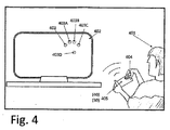
次に図4を参照すると、ユーザの指の運動の近似的表現を示すデータを表示するために本発明の原理を利用する技術が例示されている。したがって、例とされているユーザは、前記近似的表現を示すデータを表示するために本発明のシステムを操作する。システムは、一般的に、センサマトリックスを組み込んだハンドヘルドデバイスによって形成され、外部コンピュータデバイス(例えば、ディスプレイデバイス)に無線接続可能である上述のシステム600として構成され、本発明の監視ユニットは、ハンドヘルドデバイス内に組み込まれるか、またはディスプレイデバイスに関連付けられる(組み込まれるか、または結合される)。そこで、監視ユニットを組み込んだデバイスは、ハンドヘルドデバイス30またはディスプレイデバイス40とすることができる。
Referring now to FIG. 4, a technique that utilizes the principles of the present invention to display data representing an approximate representation of a user's finger movement is illustrated. Thus, the example user operates the system of the present invention to display data representing the approximate representation. The system is generally configured as a
ユーザは、片手でデバイスを持ち、もう一方の手/指をハンドヘルドデバイス30の上に置き、タッチ、ホバリングを行うか、または離れた位置に置くことができる。例えば、指先は、ハンドヘルドデバイス30内のセンサマトリックス(図示せず)によって検出され、その挙動を示す変換された測定データ(表示できるようにフォーマットされている)が遠隔画面デバイス40に伝送されるか、または測定データ(生データ)がその画面に送られ、表示フォーマットに変換される。この図では、画面上に表示されるスポット403、403A、403B、403C、および403Dは、デバイス30のセンサマトリックス(センシング表面405)に対して特定の位置にあるユーザの指先に対応する。非限定的な例によれば、スポットの色および/または明るさは、対応する指先の絶対的な高さまたは相対的な高さを示す。したがって、ユーザの手もしくは指の挙動は、画面上に近似的に表現することができ、手/指の運動は、適切なセンシングおよび運動データ変換により、手/指の位置から離れた場所で追跡することができる(または一般的に、その挙動を監視することができる)。後者では、離れている場所の表面/形状上の近似的表現がユーザの手の各部分の間の位置関係、さらにはセンシングパッドに関する位置関係も維持する。これらのスポットを追跡して、ジェスチャを検出するか、または選択を実行するといったことを行える。
The user can hold the device with one hand and place the other hand / finger on the
用途は、適宜、固定ディスプレイ402(ほとんどの場合、比較的大きい)が接続され、隔たった高さから複数の指を検出し、例えば、ユーザの指、手のひら、手、またはその一部の挙動を伝達することができるデバイス表面405上で指404を使ってシステムとやり取りするユーザ401から比較的離れた範囲内に適宜配置されているメディアセンタ、ビデオゲーム機、または通常のPCなどのコンピュータベースのシステム(またはホスト)である。例えば、ディスプレイ402は、ユーザの手の近似的表現をもたらす。この近似的表現は、ユーザの手の5つの部分、すなわち、指先の表現403、403A〜Dを含む。適宜、表現されるそれぞれの部分は、色、形状、シルエット、またはパターンおよび同様のものもしくはそれらの組み合わせなどの視覚的指示によって一意に識別される。それに加えて、1つまたは複数の部分の距離は、色、形状、シルエット、またはパターンおよび同様のものもしくはそれらの組み合わせによって示すことができる。指の挙動は、ベクトル空間の三次元座標による指先の位置、指先(または手のひらなど)の各高さ、識別されたジェスチャ(三次元空間内のモーションジェスチャを含む)、高さマップイメージ表現を含むことができ、ユーザの指の相対的配置は監視されている指の透視投影を含むものとすることができる。
Applications include a fixed display 402 (which is relatively large in most cases) connected as appropriate to detect multiple fingers from separated heights, e.g., the behavior of a user's finger, palm, hand, or part thereof. Computer-based, such as a media center, video game machine, or regular PC, that is suitably placed within a relatively remote area from the
例えば、図4は、ユーザの手の複数の部分が他の部分と比較して近接センサマトリックスに近いことを示している。この例では、中指部分403aおよび403bは、暗色で示すことによって近接センサマトリックスに近いとして示されている。 For example, FIG. 4 shows that portions of the user's hand are closer to the proximity sensor matrix compared to other portions. In this example, the middle finger portions 403a and 403b are shown as close to the proximity sensor matrix by showing in dark color.
監視されている挙動は、ユーザの手の他の部分の相対的位置決めも含みうる。これらの指の挙動は、ホストに伝送することができ、ホストは、一実施形態では、受け取った挙動を表示する。ホスト上で実行される専用モジュールは、元イメージと重なる指部分などの対象物の挙動を、ユーザインタラクションおよび制御を目的としてユーザが下にある元イメージを見て、それぞれの指の挙動情報を使用することができるように表示することができる。例えば、この点で、画面の元イメージ上でのユーザの指先の挙動の半透明表示を想定することができる。一実施形態では、本発明のデバイスもしくはシステムは、指の挙動をコンピュータベースのシステムに無線伝送する。有線または無線の近接センサ表面も、本発明の範囲内に含まれる。ホストは、適宜、コンピュータベースのシステムと通信することができる。 The behavior being monitored can also include relative positioning of other parts of the user's hand. These finger behaviors can be transmitted to the host, which in one embodiment displays the received behavior. A dedicated module executed on the host uses the behavior information of each finger by looking at the underlying image for the purpose of user interaction and control. Can be displayed as you can. For example, in this respect, a translucent display of the behavior of the user's fingertip on the original image of the screen can be assumed. In one embodiment, the device or system of the present invention wirelessly transmits finger behavior to a computer-based system. Wired or wireless proximity sensor surfaces are also included within the scope of the present invention. The host can communicate with the computer-based system as appropriate.
本発明では、指先のタッチ(または非常に近い位置でのホバリング検出)を単に識別するのではなく、ユーザの手の挙動を場合によっては三次元空間の座標空間内のユーザの手またはその一部の近似的表現に変換し、これにより、リビングルームのシナリオにおける従来の制御装置を、例えば、新しいレベルの人間工学および設計へと改善する。 The present invention does not simply identify a fingertip touch (or hovering detection at a very close position), but the behavior of the user's hand, in some cases, the user's hand or a part thereof in the coordinate space of the three-dimensional space. This improves the conventional controller in the living room scenario, for example, to a new level of ergonomics and design.
検出された指および手も、監視できる(または例えば、表示されるイメージの上に複数の記号403またはイメージとしてセンシング表面405からかなりの距離のところにある間に表示される)。この距離は、0から3cm、1から4cm、1から5cm、2から5cm、2から6cm、および3から7cmまでの範囲とすることができる。本発明のデバイスおよびセンシング表面405は、仮想物体、ボタン、または適宜表示できる任意の形状、寸法、配向、もしくはパターンの特徴をアクティブ化することができる。したがって、指などの対象物の1つまたは複数の部分を、タッチまたはタッチレスモード(センシング表面との近接度0)のいずれかで仮想物体、ボタン、または特徴の上に配置することができる近似的表現で表現または表示することが可能である。それに加えて、接触および非接触の移動もしくは離れた移動を含む挙動または対象物の監視を利用して、ディスプレイ画面上に表示される仮想物体の全方向へのドラッグ、移動、操作(ジェスチャによる)、ズームイン/アウト、3D回転、およびパニングを行うことができる。これに関して、「タッチ」および「ホバリング」という用語は、「接触」および「非接触」という用語とそれぞれ入れ替えて使用できる。いくつかの実施形態では、ドラッグ、移動、操作、ジェスチャ、および他の機能も三次元座標空間内で監視することができる。それに加えて、手を使った予め定義されたジェスチャを使用して、予め定義された、またはプログラムされているアクションを選択することができる。これらは、特定の表示される物体に向けられてもよいし、向けられなくてもよい。
Detected fingers and hands can also be monitored (or displayed, for example, as a plurality of
視覚フィードバック、聴覚フィードバック、および感覚フィードバックは、物体およびその一部の挙動を示すために使用され、これらのフィードバックは、タッチまたは非タッチ操作、ホバリング挙動、離れた挙動、ドラッグ、ジェスチャ、および同様のものの検出を指示することができる。 Visual feedback, auditory feedback, and sensory feedback are used to show the behavior of an object and its parts, and these feedback can be touch or non-touch, hovering behavior, distant behavior, dragging, gestures, and similar You can instruct the detection of things.
ユーザの手および/または指などの、対象物の一部分を近似的に表現するための可能な別の方法では、シルエット、相対的位置および/または監視されている対象物の挙動に呼応して適応する形状を利用することができる。適宜、この表現のサイズは、監視されている対象物が近くなるにつれて、またはセンシング表面から遠ざかるにつれて増大または減少しうる。 Another possible method for approximating a part of an object, such as the user's hand and / or finger, adapts to the silhouette, relative position and / or behavior of the object being monitored. The shape to be used can be used. Optionally, the size of this representation may increase or decrease as the object being monitored is closer or away from the sensing surface.
本発明によれば、変換は仮想点(物体位置から離れた場所で使用される点)と物体の付近で感知されるような対象物の部分の対応する視点との間の位置関係を保持する。したがって、さらに他の可能な実装では、監視されている対象物の一部の相対的位置決めを保持する物体表現を構成するために形状、サイズ、または他の効果(視覚的などの)を利用することができる。 According to the invention, the transformation preserves the positional relationship between virtual points (points used away from the object position) and the corresponding viewpoint of the part of the object as perceived in the vicinity of the object. . Thus, still other possible implementations utilize shape, size, or other effects (which are visual) to construct an object representation that retains the relative positioning of the portion of the object being monitored be able to.
本発明は、特定の数の点(視点または仮想点のいずれか)に限定されないことに留意されたい。一般的に、これは、センサマトリックス内のセンサの個数、または場合によっては、適切な補間アルゴリズム(これは点の数を増やす)によっても定義されうる。 It should be noted that the present invention is not limited to a specific number of points (either viewpoints or virtual points). In general, this can also be defined by the number of sensors in the sensor matrix, or possibly by an appropriate interpolation algorithm (which increases the number of points).
いくつかの実施形態では、この位置関係は、対象物の対応する部分からセンシング表面までの距離を含む。その代わりに、またはそれに加えて、この位置関係は、監視されている対象物の2つまたはそれ以上の対応する部分の間の距離を含む。言い換えると、位置関係は、対象物の対応する部分(透視投影)と仮想点との空間的(体積)配置構成を含む。また、位置関係は、(1)対象物のどの部分が近接センサマトリックスに最も近いか、(2)対象物のどの部分が近接センサマトリックスから最も遠いか、(3)それらの間の最も近い隣接要素である対象物の複数の対応する部分を示す比較データのうちのどれかを示すものとすることができる。センサマトリックスは、測定データを生成して処理し三次元表現を構成することができ、これにより対象物の少なくとも一部の奥行きを認知できることを理解されたい。 In some embodiments, this positional relationship includes the distance from the corresponding portion of the object to the sensing surface. Alternatively or additionally, this positional relationship includes the distance between two or more corresponding portions of the monitored object. In other words, the positional relationship includes a spatial (volume) arrangement configuration of a corresponding portion (perspective projection) of the object and a virtual point. Also, the positional relationship is (1) which part of the object is closest to the proximity sensor matrix, (2) which part of the object is farthest from the proximity sensor matrix, and (3) the nearest neighbor between them. It may indicate any of comparison data indicating a plurality of corresponding portions of an object that is an element. It should be understood that the sensor matrix can generate and process measurement data to construct a three-dimensional representation, thereby recognizing the depth of at least a portion of the object.
いくつかの実施形態では、監視ユニットのプロセッサは、代表的な幾何学的形状、形、パターン、および/または印を持つ対象物の一部分を割り当てるように事前にプログラムされる。これらは、仮想座標系内に位置(3D)を有することができる。 In some embodiments, the processor of the monitoring unit is pre-programmed to allocate a portion of the object having a representative geometric shape, shape, pattern, and / or indicia. They can have a position (3D) in a virtual coordinate system.
近似的表現は、射影表面(例えば、ディスプレイ)上に出現する所定のパターン(いわゆる「元(original)イメージ」)上への仮想点の射影を利用することができる。所定のパターンは、発明の用途が異なれば異なることがある。例えば、ユーザの手は、タッチ、ホバリング、3Dジェスチャ、回転などを含むユーザの手の挙動に関して2つの異なる記号または形状(または他の何らかの視覚効果)を有する専用のカーソルとして近似的に表現することができる。専用のカーソルまたは他の表現は、センシング表面からユーザの手の一部までの距離を反映しうる。この表現は、監視される物体の距離、透視投影、配向、セグメント分割の特徴を示す視覚効果の形態を取りうる。例えば、物体のホバリングは、センシング表面に近づくにつれて明るさを増す明るいイメージ内の物体として表示することができる。照明効果は、連続的でもよいし、光度を段階的に変化させるものであってもよい。 The approximate representation can utilize the projection of virtual points onto a predetermined pattern (so-called “original image”) that appears on the projection surface (eg, display). The predetermined pattern may be different for different uses of the invention. For example, the user's hand should be approximately represented as a dedicated cursor with two different symbols or shapes (or some other visual effect) with respect to the user's hand behavior including touch, hover, 3D gesture, rotation, etc. Can do. A dedicated cursor or other representation may reflect the distance from the sensing surface to a portion of the user's hand. This representation may take the form of a visual effect that indicates the distance, perspective projection, orientation, and segmentation characteristics of the monitored object. For example, object hovering can be displayed as an object in a bright image that increases in brightness as it approaches the sensing surface. The lighting effect may be continuous, or may change the light intensity stepwise.
他の可能な方法では、物体が表面に近づくにつれてますます小さくなる(またその逆もある)適応的に変化する形状および/またはサイズを利用することができる。したがって、本発明は、専用のカーソルのターゲットを仮想的な特徴または点に定める操作を改善することができる。 Other possible methods may utilize adaptively changing shapes and / or sizes that become increasingly smaller as the object approaches the surface (and vice versa). Thus, the present invention can improve the operation of targeting a dedicated cursor to a virtual feature or point.
次に図5Aから5Dを参照すると、そこではセンシングデータおよび対応する変換データまたは近似的表現の生成のため本発明で使用するのに適している技術が例示されている。図5Aに示されているように、ユーザの一方の手の指501は、センシング表面520の上に位置しているが、他方の手502の指は、センシング表面520に接触(タッチ)している。指部分501は、センシング表面に対して特定のゼロでない距離のところに配置されているが、指部分502は、距離ゼロのところに配置されている。図5Bは、センサマトリックスによって生成される測定データに対応する高さマップイメージデータを示している。異なる高さの値は、センシング表面520にある物体の、一般に501'で表される、点の輝度変化によって示すことができる。したがって、図5Bに示されているデータは、近接センサマトリックスを使用する近接度測定によって得られる3D測定データに対応する。次いで、このデータは、監視されている対象物の近似的表現に変換される。上に示されているように、このような変換は、近接マトリックス側に、または遠隔のディスプレイ側のいずれかにあるプロセッサによって実行される。図5Cおよび5Dに示されているように、計算された指先位置(変換結果)が遠隔の画面上に提示される。図5Cでは、この提示に異なる色(濃淡レベルまたは透明度レベル)を使用し、センシング表面に対して、したがって画面に対して、三次元空間内の物体の部分に対応する仮想点(異なる高さ値)を例示している。ここでは、物体の近似的表現は、半透明の記号504、504a〜dおよび505を使用して所定のパターン(背景の印)の上に形成される。この視覚に訴える技術は、所定のパターンに対するグラフィックの最小限度の干渉が必要な仮想的な特徴または物体のターゲット設定および制御の改善のためのものとすることができる。透明度レベルは、高さ/近接度を示すことができる。非制限的な例により、センシング表面520に手501よりも手502が近いと、その各記号505(指先部分を表す)は手501の指部分を表す記号504ほど透明でない。図5Dは、図5Bに示されているものに対応する測定データの近似的表現を表示するための他の可能な表示技術の例を示している。ここで、透視投影イメージ506は、引き延ばされ、元の画面イメージ(背景の印)
が差し挟まれている。表示(変換)データ506内の仮想点の位置関係は、センシング表面の付近の物体の部分/点(すなわち、本発明の例における実際の指と他の手の部分)の間の位置関係に対応する。
Reference is now made to FIGS. 5A-5D, which illustrate techniques suitable for use in the present invention for the generation of sensing data and corresponding transformed data or approximate representations. As shown in FIG.5A, the
Is inserted. The positional relationship of the virtual points in the display (transformation)
本発明は、さまざまな用途で使用することができることに留意されたい。例えば、本発明は、仮想ドメイン(または仮想座標系)内で対象物を近似的に表現するために使用することができ、またこの表現を使用して仮想物体を制御し、適宜操作することができる。他のいくつかの例では、本発明の技術を使用することで、仮想表示キーパッドを使用してキーボードを実装することができ、さらには、シングルタッチまたはマルチタッチのジェスチャ、ライティング/スケッチングパッド(writing/sketching pad)、アクティブ化および制御に使用できる3Dジェスチャデバイス、対象物の特定の一部/部分(ユーザの手の指)を認識するように構成されたジェスチャを使用して特徴をアクティブ化することができる。 It should be noted that the present invention can be used in a variety of applications. For example, the present invention can be used to approximately represent an object in a virtual domain (or virtual coordinate system), and this representation can be used to control and appropriately manipulate a virtual object. it can. In some other examples, the technique of the present invention can be used to implement a keyboard using a virtual display keypad, and even a single-touch or multi-touch gesture, writing / sketching pad Activating features using (writing / sketching pad), 3D gesture devices that can be used for activation and control, gestures configured to recognize specific parts / parts of the object (the fingers of the user's hand) Can be
仮想座標空間、または対象物の挙動の近似的表現を反映する表示内の領域および透視投影は、特定の用途に応じて動的に適合させることができる。例えば、カーソルを移動するために使用する場合、監視されている物理的オブジェクトの近似的表現を反映するためにディスプレイを使用することができる。適宜、仮想3Dキーボード上でタイピングするために使用する場合、仮想キーボードとの相対的関係において物体の表現をディスプレイに反映することができる。センサマトリックスが組み込まれ、センシング表面を画成する入力デバイスで使用される技術は、知られている任意の好適なタイプのものとすることができることに留意されたい。センサマトリックスは、プロセッサ内に内蔵されるか、または結合されるとともに、適切な処理ユーティリティ(ハードウェアおよびアルゴリズム)を使用し、図5Bの例に関して上で説明されているように近接度/高さ測定またはマップイメージを得る。センサマトリックスは、静電容量性近接センシング表面を使用することができる。この場合、マトリックスは、センサパッドの配列(例えば、二次元配列)で形成される。 The virtual coordinate space, or the region in the display that reflects an approximate representation of the behavior of the object, and the perspective projection can be dynamically adapted depending on the particular application. For example, when used to move a cursor, the display can be used to reflect an approximate representation of the physical object being monitored. Where appropriate, when used for typing on a virtual 3D keyboard, the representation of the object can be reflected on the display relative to the virtual keyboard. It should be noted that the technology used in the input device that incorporates the sensor matrix and defines the sensing surface can be of any suitable type known. The sensor matrix can be embedded in or combined with the processor and using appropriate processing utilities (hardware and algorithms), and proximity / height as described above with respect to the example of FIG. Get a measurement or map image. The sensor matrix can use a capacitive proximity sensing surface. In this case, the matrix is formed by an array of sensor pads (for example, a two-dimensional array).
静電容量性近接センサマトリックスは、Z次元(近接度/距離測定)だけでなくマトリックス平面(X,Y)またはセンシング表面にそった位置を与えることができる。静電容量方式は、さまざまな用途に幅広く使用されており、特に、位置/運動が、照明具が破壊される、機械的ストレスがかかるなどの極端な環境条件の下で追跡される場合に使用される。静電容量方式の原理は、それ自体知られており、本発明の一部をなさない。このような方法は、デバイスを単純でコンパクトなものにし、さらには費用効果を高めることができるという事実により、本発明のハンドヘルド入力デバイスにおいて有利に使用されうる。 Capacitive proximity sensor matrices can provide positions along the matrix plane (X, Y) or sensing surface as well as the Z dimension (proximity / distance measurement). Capacitive methods are widely used in a variety of applications, especially when the position / movement is tracked under extreme environmental conditions such as lighting fixtures breaking or mechanical stress Is done. The principle of the capacitive system is known per se and does not form part of the present invention. Such a method can be advantageously used in the handheld input device of the present invention due to the fact that the device can be simple and compact, and even cost effective.
静電容量センサベースのセンシング表面では、電気回路の静電容量の変化を引き起こす物理的本体部の能力を利用する。これに関して、図6A〜6Dを参照する。図6Aは、センサマトリックスのセンシングパッド603およびその関連する電気回路を例示している。図6Bに示されているように、導電性材料から作られるパッド(PAD)603は、コンデンサ604の2つのプレートのうちの一方のプレートを提示する。パッド603は、近接センシングマトリックスによって画成されるX-Yセンシング表面内の知られている二次元位置に配置される。
Capacitive sensor-based sensing surfaces take advantage of the physical body's ability to cause changes in the capacitance of the electrical circuit. In this regard, reference is made to FIGS. FIG. 6A illustrates a
ユーザの指601をパッド603に近づけると、アースに対し平板コンデンサが形成される。指がセンシングパッド603に近ければ近いほど、コンデンサ604上で測定される等価静電容量は大きくなる。電源602は、センシングパッド603に電気的に接続されており、AC電圧源とすることができる。等価静電容量が大きければ大きいほど、それが及ぼすインピーダンスは小さくなる。したがって、測定されたAC信号(すなわち、増幅器605の出力)の大きさも減少する。あるいは、電源は、DC電流源とすることもできる。等価静電容量が大きければ大きいほど、一定の電荷期間の終わりに測定される電位は小さくなる。図6Dに例示されているように、適宜、近接センサパッドの電源をユーザの身体に取り付ける(例えば、ユーザが近接センサ表面を手に持つ場合に、この取り付けは確実である)。指がパッドに近ければ近いほど、パッドにおける電界は強くなり、そのため、電圧測定値は高い値になる。回路素子は、同じ電位を基準とし、したがって、測定感度は上昇する。
When the user's
図6Cは、「シャント静電容量」と呼ばれる技術が使用される一例に対応している。励起源(電源)611は、受信機パッド613への電界を発生する送信機パッド612に接続される。受信機パッド613で測定された電気力線614は、電圧測定値に翻訳される。指615、または他の接地された物体が、電界に緩衝する場合、電気力線の一部はアースへ分流され、受信機パッドには到達しない。したがって、電圧測定値は減少する。
FIG. 6C corresponds to an example in which a technique called “shunt capacitance” is used. The excitation source (power source) 611 is connected to a
センサマトリックス要素毎に(パッド毎に)、センシング表面からの距離/近接度に対する信号強度または電位の依存関係を記述する関数は、一般に知られ、例えば、較正手順で決定することができる。このような関数の例は、図6Eに示されている。この例は、静電容量測定に関して、電圧と高さの関数に対応しており、その場合、電源はAC電圧源であり、回路パラメータは、以下のとおりである。電源周波数Fは400KHzであり、電源の電圧Vは1Vであり、抵抗器Rは1MOhmであり、空気の誘電率ε0は8.85e-12であり、平板面積Aは64μmであり、平板の間の距離dは1から30mmまで変化する。コンデンサ上の測定電圧Vcapは、分圧器公式
Vcap=V・jXc/(jXc+R)
によって与えられ、Xcはコンデンサのインピーダンスである。
For each sensor matrix element (for each pad), a function describing the dependence of signal strength or potential on distance / proximity from the sensing surface is generally known and can be determined, for example, by a calibration procedure. An example of such a function is shown in FIG. 6E. This example corresponds to a function of voltage and height for capacitance measurement, in which case the power supply is an AC voltage source and the circuit parameters are as follows: Power supply frequency F is 400KHz, power supply voltage V is 1V, resistor R is 1MOhm, air permittivity ε 0 is 8.85e-12, plate area A is 64μm, between plates The distance d varies from 1 to 30 mm. The measured voltage V cap on the capacitor is the voltage divider formula
V cap = V ・ jX c / (jX c + R)
Xc is the impedance of the capacitor.
平板コンデンサ公式を使用すると、これは
Vcap=V・[d/sqrt(d2+(2π・F・R・ε0・A)2]
に展開できる。
Using the plate capacitor formula, this is
V cap = V ・ [d / sqrt (d 2 + (2π ・ F ・ R ・ ε 0・ A) 2 ]
Can be deployed.
したがって、距離/近接度の関数として測定信号に対し較正曲線を使用すると、センシングパッドからの対象物(例えば、手の指部分)の距離を決定することができる。AC電圧ベースの構成の場合、対象物の近接度は、測定信号の位相の変化に従って決定されうる。 Thus, using a calibration curve for the measurement signal as a function of distance / proximity, the distance of an object (eg, a finger portion of a hand) from the sensing pad can be determined. For an AC voltage based configuration, the proximity of the object can be determined according to the change in phase of the measurement signal.
影響のある静電容量は、ローパスフィルタの一部であってもよいことに留意されたい。測定位相は、等価静電容量の関数、すなわち、高さと近接度との関数である。この構成が使用される場合、位相シフトを計算するためにAC電源の位相が知られているか、または推定されなければならない。高さまたは近接度を計算するために、適宜、位相と大きさの両方が使用される。 Note that the affected capacitance may be part of the low pass filter. The measurement phase is a function of equivalent capacitance, that is, a function of height and proximity. If this configuration is used, the phase of the AC power source must be known or estimated to calculate the phase shift. Both phase and magnitude are used as appropriate to calculate height or proximity.
位置データの第1のレベルまたは低レベルの処理は、いわゆる「高さマップイメージデータ」の形態で測定データを取得する(変換を受ける)ことを目的としている。これは、センサマトリックスユニット、または変換も実装する監視ユニットの前記プロセッサユニットもしくはコンピュータモジュールにあるデジタル処理ユニット(DSP)において実行されうる。上で示されているように、監視ユニットは、センサマトリックスも組み込んだ入力デバイスの一部であるか、または遠隔電子デバイス(例えば、ディスプレイ)の一部とすることができる。同じ、または異なるDSPは、こうして、近接センサマトリックスの付近で、近接センサマトリックスに対して対象物の挙動を示すデータを決定し、それを示す測定データを生成し、その測定データを仮想座標空間内の近似的表現に変換することができる。近似的表現は、いわゆる「透視投影」表現である場合もそうでない場合もある。 The first level or low level processing of the position data is intended to obtain measurement data (subject to conversion) in the form of so-called “height map image data”. This can be performed in a sensor matrix unit or a digital processing unit (DSP) in the processor unit or computer module of the monitoring unit that also implements the transformation. As indicated above, the monitoring unit can be part of an input device that also incorporates a sensor matrix or can be part of a remote electronic device (eg, a display). The same or different DSPs thus determine, in the vicinity of the proximity sensor matrix, data indicating the behavior of the object relative to the proximity sensor matrix, generate measurement data indicating it, and store the measurement data in the virtual coordinate space. Can be converted to an approximate representation of The approximate representation may or may not be a so-called “perspective projection” representation.
本発明の目的のために使用するのに適しているセンシングパッド配列には多数の配置構成が考えられる。しかし、簡単のため、特定の、ただし非制限的な例について以下で説明する。 Many arrangements of sensing pad arrangements suitable for use for the purposes of the present invention are possible. However, for simplicity, specific but non-limiting examples are described below.
これに関して、図7Aおよび7Bを参照すると、それぞれ、2Dセンサマトリックス配置構成701および関係する電気回路が示されている。それぞれのセンシングパッド706は、アナログ増幅器702を有する。AC電源信号707が、電気回路に供給される。増幅器の出力は、アナログ/デジタルコンバータ703によってサンプリングされ、それらのサンプルは、さらに分析するために、CPU 704に転送される。いくつかの実施形態では、信号源(給電電圧信号)は、正弦波または方形波発振器によって構成され、大きさの測定は、サンプル上で離散フーリエ変換(DFT)を実行することによって得られる。DFT法は、当技術分野で知られており、詳細に説明される必要はない。他のいくつかの実施形態では、静電容量測定値は、ハードウェアによってDCレベルに翻訳され、増幅器702の出力は整流され、出力の大きさに比例するDCレベルに合わせてフィルタ処理される。これは、サンプリング手順の前に実行することができる。
In this regard, referring to FIGS. 7A and 7B, a 2D
適宜、複数の増幅器をサポートするために、いくつかの入力チャネルを持つアナログ/デジタルコンバータ703を使用することができる。この例で必要な増幅器の数は、センシング表面の表面積によって決まる。適宜、複数のプロセッサ(CPU)が使用され、それぞれデバイスの異なる表面領域(パッドの異なるグループ)に対して使用される。処理結果は、送信機705を介して伝送される。
Optionally, an analog /
適宜、容量/デジタル変換チップを使用してそれぞれのセンシングパッドに関連する静電容量を推定する。 Where appropriate, a capacitance / digital conversion chip is used to estimate the capacitance associated with each sensing pad.
図8Aおよび8Bを参照すると、本発明で使用するのに適している近接センサユニットの構成および動作の一例が示されている。図8Aに示されているように、電圧信号811が、センシング表面(例えば、単一パッドのセンシング表面)812に印加されると、電気力線813はあらゆる方向に伝搬する、すなわち、電気力線は散乱する。これにより、センサ(パッドまたはマトリックス全体)の「視野」または「センシングゾーン」が広がり、これにより、センシング表面と正確には揃っていない物体の感知が可能になる。例えば、空間領域817の付近に配置されている、ユーザの手などの対象物は、セグメント819にある対象物を表す電気信号として検出されうる。その結果、位置逸脱821が生じ、センシング表面から抽出された位置情報がわかりにくくなる。逸脱821は、センシング表面を囲むフレームを利用することによって防止または実質的に排除することができる。これは、図8Bに例示されている。
Referring to FIGS. 8A and 8B, an example of the configuration and operation of a proximity sensor unit suitable for use with the present invention is shown. As shown in FIG. 8A, when a
図示されているように、1つまたは複数の導電性材料から作られたフレーム854は、近接センサマトリックスのセンシング表面(例えば、パッド)を(少なくとも部分的に)囲む。近接センサマトリックスおよびフレームは、DC電源もしくはAC電源のいずれかとすることができる電源ユニット851および855に電気的に接続される。電圧源855によって電流を流すことによって、電界853の集束力が高まるか、または平行度が高まる。読み出しにこの技術を利用することによって、位置と高さの両方の読み取りがより正確になる。フレームによって囲まれるセンシング表面が高さマップの取得に使用される場合、得られるイメージはより正確になる。センシング表面(パッド)とともにフレームを使用した場合も、デバイスを持つ手の影響がなくなる。図8Bに例示されているように電気力線を操作するために、センシング表面の裏部と側部は、センシングパッドそれ自体として電圧源855によって同じ電圧を印加される導電性フレーム854によって囲まれている。フレーム(ガード)とセンシングパッドとの間に電位差がないので、それらの間に電界もない。その結果、センシングパッドの脇または背後に配置されている、導電性の物体(例えば、デバイスを持っている手)は、センシングパッドとではなくむしろガードとともに電界を形成する。センシングパッドについては、そのガードされていない表面領域のみが、導電性の物体と電界を形成することが許される。
As shown, a
マトリックスのセンシング表面を囲む導電性フレームを使用することに加えて、またはその代わりに、他の技術を使用することもでき、これに従って、センサマトリックス内のそれぞれのパッドは本質的に類似のより集束度の高い電気力線をもたらす他のパッド(上述のフレームとして働く)で囲まれる。この効果は、すべてのパッドからの伝送または感知によって同時に引き起こされる。特定のセンシングパッドを囲むパッドが、前記特定のセンシングパッドの「電界ガード(electric field guard)」として働く。適宜、回路中間層ビア(PCB層を貫通する導電性スルーホール)を使用して上述のフレームの側部が実装される。 In addition to or in place of using a conductive frame surrounding the sensing surface of the matrix, other techniques can also be used, according to which each pad in the sensor matrix is essentially more focused than similar. Surrounded by other pads (acting as the frame described above) that provide high lines of electrical force. This effect is caused simultaneously by transmission or sensing from all pads. A pad surrounding a specific sensing pad serves as an “electric field guard” for the specific sensing pad. Where appropriate, the side portions of the frame are mounted using circuit intermediate layer vias (conductive through holes through the PCB layer).
図7Aおよび7Bに戻って参照すると、すべてのセンシングパッド706に関連付けられているハードウェア回路は、増幅器702、A/Dコンバータ703(またはA/Dチャネル)、およびCPU 704とのインターフェイス線を備えていることがわかる。増幅器およびA/Dコンバータは、「センシングパッドインターフェイス」または「インターフェイス」とさらに称される。いくつかの実施形態では、高分解能近接センサマトリックスが必要になり、したがってマトリックス内のセンシングパッドの数をかなり増やす必要がある場合、近接センサマトリックス内のインターフェイスの数を減らすのが必須である。
Referring back to FIGS. 7A and 7B, the hardware circuitry associated with all sensing
図9は、センシングパッドの配列から読み出すのに適している時分割法の原理を説明した図である。1バッチ分のセンシングパッド901(2つ以上のパッド)が単一のインターフェイス903に接続される。与えられた時間に、そのバッチからのただ1つのセンシングパッドがインターフェイスに接続される。これは、スイッチ902を使用することによって行うことができ、その状態はCPU(図7Bの704)に知られている。バッチ901のサイズは、インターフェイスの必要総数を定める。バッチのサイズが大きければ大きいほど、インターフェイスの必要数は少ない。
FIG. 9 is a diagram for explaining the principle of the time division method suitable for reading from the array of sensing pads. One batch of sensing pads 901 (two or more pads) is connected to a
本発明において使用するのに適している当技術分野で知られている別の技術は、周波数分割である。2つ以上のセンシングパッド901を共通のインターフェイスに同時に接続することができ、それぞれのパッドは互いに関して直交する周波数で励起される。この実施形態では、相互インターフェイスによって2つ以上のパッドを同時に処理することができる。その結果、インターフェイスは、信号の総和を生成する。直交しているため、それぞれの周波数は、その総和から分離されるか、またはそれと別に分析されうる。それぞれの周波数分析の結果は、それが由来する対応するパッドに関連付けられる。
Another technique known in the art that is suitable for use in the present invention is frequency division. Two or
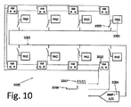
使用するセンシングパッドの個数が多い場合(例えば、数百個もしくは数千個のセンサパッド)、信号線とスイッチ制御線の配線はかなり複雑なものになる。このような場合に配線を簡素化するために、複数のセンシングパッドの他の配置構成および動作を利用することができる。これは、図10に例示されている。ここでは、一般に1002で参照される、複数のパッドが、共通インターフェイス1004に結合されるように配列される。所望の時間枠を確保しやすくするために分散型シフトレジスタスキーム1005が使用されており、この時間枠内で、それぞれのパッドはインターフェイスに別々に結合され、これにより、異なる時間枠/スロットで相互インターフェイスを介して複数のセンシングパッドから測定結果を得ることができる。
When a large number of sensing pads are used (for example, hundreds or thousands of sensor pads), the wiring of signal lines and switch control lines becomes quite complicated. In order to simplify the wiring in such a case, other arrangement configurations and operations of the plurality of sensing pads can be used. This is illustrated in FIG. Here, a plurality of pads, generally referred to as 1002, are arranged to be coupled to a
これから詳述されるように、回路配線の簡素化および柔軟性のほかに、この構成には、静電容量がDCレベルに翻訳される実施形態において利用することができる別の利点がある。配線1001は、パッドの近くにある各スイッチ1003を介してセンシングパッドを接続し、インターフェイス1004に接続されている。スイッチ1003は、分散型シフトレジスタによって制御される。非制限的な例において、分散型シフトレジスタは、一般的には本明細書で説明されている機能を実現するフリップフロップ型配置構成であるDフリップフロップ1005構成を介して実装される。それぞれのDフリップフロップ1005(シフトレジスタの一構成要素)は、センシングパッドに近接して配置される。例示的な例として、パルス1006が第1のDフリップフロップ1020に送られると、第1のパッドがインターフェイス1004に電子的に結合される。次のクロックパルス1007の結果、第2のパッドのみがインターフェイスに結合され、というように続く。この実施形態の利点の1つは、中央スイッチングユニットおよび複雑な経路指定または配線が不要になることである。一構成において、経路指定は、単一層内において実行されうる。
As detailed below, in addition to the simplicity and flexibility of circuit wiring, this configuration has another advantage that can be utilized in embodiments where the capacitance is translated to the DC level. The
いくつかの実施形態では、静電容量との特定の関係にある(例えば比例する)DCレベルを取得することによって静電容量測定が実行される。図10に例示されている配置構成では、リフレッシュサイクル時間全体を使用して測定値を積分する。これにより、静電容量測定の感度が向上する。特定のパッドがインターフェイスに結合されていない間であっても測定結果が得られる。したがって、リフレッシュサイクル全体を使用して、すべてのパッドに対する近接度測定結果を平行して得ることができる。この背景状況におけるリフレッシュサイクル時間は、高さマップイメージを更新するのに要する時間を意味する。積分時間が終わるまでに、結果として得られるDCレベルは、図10に例示されている配置構成を使用することでかなり高速に読み取られる。 In some embodiments, a capacitance measurement is performed by obtaining a DC level that is in a specific relationship (eg, proportional) to the capacitance. In the arrangement illustrated in FIG. 10, the entire refresh cycle time is used to integrate the measurement. Thereby, the sensitivity of capacitance measurement is improved. Measurement results are obtained even while a particular pad is not coupled to the interface. Thus, the entire refresh cycle can be used to obtain proximity measurement results for all pads in parallel. The refresh cycle time in this background situation means the time required to update the height map image. By the end of the integration time, the resulting DC level is read fairly quickly using the arrangement illustrated in FIG.
ハードウェアおよびDSPアルゴリズムにより、安定した測定を保証するために必要なサンプリング時間およびセンシングパッドのバッチのサイズによって決定される速度で、センシング表面の平面内の物体の2D位置決めを行い、近接度(距離)測定結果をもたらす。例えば、安定した測定に必要なサンプリング時間がTであり、バッチのサイズがNである場合、リフレッシュ速度はおおよそ1/(T×N)である。安定した測定に必要な時間Tは、例えば、1ミリ秒程度とすることができるが、他の時間間隔も使用することができる。センシング表面に1000個のセンシングパッドが備えられ、バッチサイズがN=10(すなわち、100個のセンシングパッドインターフェイス)である場合、リフレッシュ速度は100Hzである。 Hardware and DSP algorithms provide 2D positioning of objects in the plane of the sensing surface at a speed determined by the sampling time required to ensure stable measurements and the size of the batch of sensing pads, and the proximity (distance ) Brings the measurement result. For example, when the sampling time required for stable measurement is T and the batch size is N, the refresh rate is approximately 1 / (T × N). The time T required for stable measurement can be, for example, about 1 millisecond, but other time intervals can be used. If 1000 sensing pads are provided on the sensing surface and the batch size is N = 10 (ie 100 sensing pad interfaces), the refresh rate is 100 Hz.
次に図11A〜11Dを参照すると、センサマトリックスの付近(すなわち、センサマトリックスの座標系内)の物体の挙動を示す測定データを生成するためにセンサマトリックスの出力に適用される処理技術の一例が示されている。近接センサマトリックス内のセンシングパッドのセンシング表面積は、パッドの感度ゾーンの境界を画成する。特定のいくつかの実施形態では、表面積は、9mm2〜400mm2、36mm2〜400mm2、81mm2〜400mm2の範囲、さらには400mm2超である。それぞれのパッドの表面積を増やすことで、より遠くにある対象物を検出することが可能になるか、または言い換えると、感度ゾーンを広げることができる。この距離は、0から3cm、1から4cm、1から5cm、2から5cm、2から6cm、および3から7cmまでの範囲とすることができる。また、パッドの表面積を増やすと、エネルギー消費量を減らし、ハードウェアの複雑さを低減することもできる。その一方で、センシングパッドの感度ゾーンが広がると、X-Y平面内の測定の分解能が低下する(高さマップの分解能が低くなる)。図11Aは、近接センサマトリックスの上に置かれた手の高分解能マップイメージである。図11Bは、広い表面積のセンシングパッドを使用する結果として比較的低い分解能を有するセンサマトリックスから取得可能な低分解能マップイメージである。したがって、対象物の挙動は、単純なイメージ処理アルゴリズムを使用したのでは抽出できない。
Referring now to FIGS. 11A-11D, an example of a processing technique applied to the output of a sensor matrix to generate measurement data that indicates the behavior of an object in the vicinity of the sensor matrix (ie, within the sensor matrix's coordinate system). It is shown. The sensing surface area of the sensing pad within the proximity sensor matrix defines the pad sensitivity zone boundary. In certain certain embodiments, the surface area, 9mm 2 ~400mm 2, 36mm 2 ~
発明者らは、対象物の姿勢またはその一部の位置を検出するための新規性のある処理スキームを開発した。図12を参照すると、そのような処理スキーム1200が例示されている。特定の一実施形態では、対象物は、ユーザの手であり、その一部は、指先である。この処理スキームでは、監視されている対象物のモデル、例えば、ユーザの手のモデルを利用する。このモデルにより、監視されているか、または追跡されている対象物のパラメータ化を行うことができる。近接度測定結果1205(すなわち、近接センサマトリックスの出力)が、例えば、図11A〜11Dにすでに例示されている、高さマップの形態で得られる。
The inventors have developed a novel processing scheme for detecting the posture of an object or the position of a part thereof. Referring to FIG. 12, such a
非制限的な例では、手のモデルは、定義済みパラメータの集合体(または特徴集合)である。特徴集合の値は、手の特定の状態、構成、姿勢、および/または位置に対応する。このような特徴集合の例は、図11Cおよび11Dに例示されている。図11Dは、手が最大5つの手の部分によって表される手のモデルを示している。このモデルによる手の部分は、手のひら、および手のそれぞれの特定の指を記述する。特に、親指、人さし指、中指、薬指、および小指を記述する。手のこれら5つの指は、ユーザの手の挙動を表すために使用される。 In a non-limiting example, the hand model is a predefined set of parameters (or feature set). The value of the feature set corresponds to a specific state, configuration, posture, and / or position of the hand. Examples of such feature sets are illustrated in FIGS. 11C and 11D. FIG. 11D shows a hand model in which the hand is represented by up to five hand parts. The hand portion according to this model describes the palm and each specific finger of the hand. In particular, describe the thumb, index finger, middle finger, ring finger, and pinky finger. These five fingers of the hand are used to represent the behavior of the user's hand.
当業者であれば、手のモデルは、限定はしないが、親指、人さし指、中指、薬指、および小指を含む手の部分の部分集合を含みうることを理解するであろう。例えば、定義済みパラメータ(または特徴集合)値の集合体である、予め定義された手のモデルは、手の空間状態を示すものとすることができる。以下でさらに詳しく説明するように、モデルは、物体に関係する測定データの「物体に依存しない」解釈を可能にし物体の挙動の近似的表現を構成するように選択されうる。このような特徴集合の例は、図11Dに例示されている。ベクトル空間の原点は、(追跡される)手根骨1170に設定される。抽出されるパラメータは、手のひらの方向を表すベクトルと(追跡される)指先の位置を通るベクトルとがなす角度である。一般に、手のモデルは、手のひら、人さし指、および中指を含むものとすることができる。他のいくつかの例では、手の部分の他の選択結果を利用することができる。特に、手のモデルは、手のひらの方向1190をさらに含むことができる。手のひらの上に4本の指を折って、仮想物体および同様のものを掴むことができる。
One skilled in the art will appreciate that the hand model may include a subset of the hand portion including, but not limited to, thumb, index finger, middle finger, ring finger, and pinky finger. For example, a pre-defined hand model, which is a collection of predefined parameter (or feature set) values, can indicate the spatial state of the hand. As described in more detail below, the model can be selected to allow an “object-independent” interpretation of measurement data related to the object and to construct an approximate representation of the behavior of the object. An example of such a feature set is illustrated in FIG. 11D. The origin of the vector space is set to the (tracked)
以下は、本発明の「物体(ユーザ)に依存しない」データ処理ユーティリティの動作の特定の、限定しない一例である。 The following is a specific, non-limiting example of the operation of the “object (user) independent” data processing utility of the present invention.
図11Dは、手のひら1170と5本の指すべて、すなわち、人さし指1130、中指1140、薬指1150、および小指1160によって表される手のモデルを例示している。このモデルは、手のひらと指のそれぞれとの間の距離(または距離の範囲)を含む。このモデルは、例えば各指への手のひらについて引かれている距離線同士がなす可能な、また実際の角度も含む。
FIG. 11D illustrates a model of the hand represented by
図11Dの実施形態など、いくつかの実施形態では、手の原点は、手根骨として定義される。したがって、手の原点を追跡することができる。抽出されたパラメータは、手のひらの方向1190を表すベクトル/直線と手のひら1170とそれぞれの指先の位置1120、1130、1140、1150、および1160との間に引かれたベクトル/直線とがなす角度1180とすることができる。いくつかの実施形態では、指先の位置と手のひらは、高さ(近接度)測定または例えば図11Bに示されている高さマップ信号強度から抽出される。いくつかの実施形態では、手のモデルでは、指先が一般的に手のひらの原点と比較して近接センサマトリックスにより近いような手の姿勢となることを想定し、したがって、信号強度は指先の位置を示す。
In some embodiments, such as the embodiment of FIG. 11D, the hand origin is defined as the carpal bone. Therefore, the origin of the hand can be tracked. The extracted parameters are the vector / line representing the
いくつかの実施形態では、位置の識別および対象物の一部の近接度は、位置(X,Y)と近接度(Z)の測定結果のフィルタ処理を必要とする。 In some embodiments, location identification and proximity of a portion of the object requires filtering of the position (X, Y) and proximity (Z) measurement results.
図12を再び参照すると、いくつかの実施形態では、入力情報1205を取得した後に、イメージ1230の高画質化が望まれており、ノイズフィルタ処理を適用することによって実行されうる。その代わりに、またはそれに加えて、オフセットおよびドリフト補正が実行される。本発明におけるノイズ低減は、センシングパッドから得られた測定値の平均を計算することによって実行できる。典型的には、それぞれのセンサパッドの読み取り値は、複数の測定を行って平均することができる。
Referring back to FIG. 12, in some embodiments, after obtaining the
処理スキーム1200は、入力データ1205から情報を抽出する手順1240をさらに含む。この入力は、監視されている対象物の特徴を抽出するためにさらに処理することができる。抽出された特徴は、特徴ベクトルまたは集合と称することができる。これらの特徴は、対象物モデル内のそれぞれの要素の測定結果である。これらの測定は、連続的であるか、または量子化されうる。特徴ベクトルの要素は、物体の一部の位置とすることができる。
可能な1つの対象物は、ユーザの手であり、この場合、抽出される特徴は、図11Dの例に示されているものとすることができる(手のひらの方向1190を表すベクトル/直線と手のひら1170と観察可能な指の指先位置との間に引かれたベクトル/直線とがなす角度1180)。当業者であれば、それぞれの用途について好適な手のモデルまたは好適な対象物のモデルが考えられることを理解するであろう。手のひらの位置および手のひらの方向の特徴は、近接度測定結果または取得した高画質化イメージから抽出することができる。この方法で、手に基づくモデルにおける集合の特徴に対する値の測定を行うことができる。PCA(主成分分析)を使用して、図11Cに示されている手のひらの方向1190を測定することができる。第1の段階では、対象物に物体の部分の位置(または点)が割り当てられる。第1の段階の前、および/または後に、観察可能な指先(センサマトリックスの感度ゾーン内にある)または手のひらなどの対象物の位置の推定は、低分解能マップ、例えば、図11Bのものから計算することができる。
One possible object is the user's hand, in which case the extracted features can be as shown in the example of FIG. 11D (vector / straight representing
適宜、監視されている物体の部分の位置を推定する段階は、最高の極値、すなわち、近接センサマトリックスに最も近いとして検出された対象物の部分/点を見つけることによって実行されうる。他のいくつかの実施形態では、クラスタ化アルゴリズムを適用し、類似の輝度パターンを持つ、適宜複数の規則に従うクラスタを決定する。これらの規則は、監視されている物体のサイズ、およびそのエッジに対する近接度、または許容可能な限界を定義する規則であるものとすることができる。 Optionally, estimating the position of the part of the object being monitored can be performed by finding the highest extrema, ie the part / point of the object detected as being closest to the proximity sensor matrix. In some other embodiments, a clustering algorithm is applied to determine clusters that have similar luminance patterns and follow a plurality of rules as appropriate. These rules can be rules that define the size of the object being monitored and its proximity to the edges, or acceptable limits.
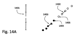
クラスタ化の結果の一例は、図13A〜13Bに示されている。図13Aは、センシング表面1301の上にユーザの手1302がかざされていることを示している。図13Bは、さらに処理をするために得られた対応する近接度マップイメージ1303を示している。セグメント化アルゴリズムが適用され、類似の高さ/近接度またはパターンのピクセル(センシングパッド)のセグメント(例えば、破線の円でマークされているセグメント1304、1305、および1306)を見つける。次いで、重心を計算することができる。
An example of the clustering result is shown in FIGS. FIG. 13A shows that the user's
発明者らは、図11Dに示されているような角度に基づく特徴集合により、手の状態または姿勢を決定することができることを発見した。角度特徴は、「ユーザに依存しない」と判明していることに留意されたい。 The inventors have discovered that an angle-based feature set as shown in FIG. 11D can determine a hand state or posture. Note that angular features have been found to be “user independent”.
特徴ベクトル内の要素の個数(見つかった角度の個数など)は変化しうることに留意されたい。特徴ベクトル内の要素の個数は、観察可能な指の数に対応する(等しい)。 Note that the number of elements in the feature vector (such as the number of found angles) can vary. The number of elements in the feature vector corresponds to (equals) the number of observable fingers.
処理スキーム1200を再び参照すると、監視されている対象物を追跡するために追跡手順1250が実行されることがわかる。
Referring back to the
追跡手順1250は、監視されている対象物の近似的姿勢を発見する段階を含みうる。典型的には、姿勢は、対象物の部分のうちのいくつかの部分の正確な位置決めを含む。対象物が手である場合、手順への入力は、前の段階で抽出された特徴集合および観察可能な指先の位置である。追跡手順は、以下の2つのサブステップに分けられる。
The
1)測定結果に最良適合する手の姿勢を発見する手順。この手順は、さらに2つの要素からなる。 1) A procedure for finding the hand posture that best fits the measurement results. This procedure further consists of two elements.
a)目に見える指(特定の高さより低く、関心領域(ROI)内にある)のタグを発見する段階。この時点で、学習HMM(隠れマルコフモデル)を使用したが、その原理はそれ自体知られており、したがって、詳しく説明する必要はない。このモデルは、32個の隠れ状態(hidden states)を含み、それぞれの状態は目に見える指の部分集合のタグ付けを表す(5本の指のそれぞれが、目に見えるか、または見えないので、32個の状態が必要である)。観察結果は、上述の抽出された特徴集合(例えば、量子化された角度)である。典型的な手の動きに合うように、標準のHMM学習ルーチンに従って状態間の遷移確率および観察結果出力確率(observation emissions probabilities)をオフラインで学習する。 a) Finding a tag for a visible finger (below a certain height and within a region of interest (ROI)). At this point, a learning HMM (Hidden Markov Model) was used, but its principles are known per se and therefore need not be explained in detail. This model contains 32 hidden states, each representing tagging of a subset of visible fingers (because each of the 5 fingers is visible or invisible). , 32 states are required). The observation result is the above-described extracted feature set (for example, quantized angle). To match typical hand movements, the transition probabilities between states and the observation emissions probabilities are learned offline according to a standard HMM learning routine.
現在の隠れ状態の探索は、オンラインでビタビ探索を実行することによって行われる。現在の観察は、一連の観察を終了するものであると考えられ、それにより、ビタビ経路を見つける(最大確率を持つ経路)。所望の隠れ状態がこの経路の最後の状態になるように選択される。HMMモデルを使用すると、親指は典型的には手のひらに垂直なレベルで90°回転させることができるが、対照的に、他の指はより限られた形でしか回転できないような効果を考えることができることに留意されたい。このモデルは、典型的には、指先と手のひらとの間の距離で適宜表される、骨のサイズを含むことができる。 The current hidden state search is performed by performing a Viterbi search online. The current observation is considered to end the series of observations, thereby finding a Viterbi path (the path with the highest probability). The desired hidden state is selected to be the last state of this path. Using the HMM model, the thumb can typically be rotated 90 ° at a level perpendicular to the palm, whereas in contrast, consider the effect that other fingers can only rotate in a more limited form Note that you can. This model can typically include bone size, appropriately expressed as the distance between the fingertip and the palm.
b)タグを指定された指先位置とのマッチングを行う。Lを、タグが与えられる前の位置ベクトルとし、Cを、タグ付けなしの現在の位置ベクトルとする。LとCとの間に完全な二部グラフを構築する。ハンガリアン法を使用して、目的関数が距離の最小総和である、LとCとの間の最適なマッチを見つける。タグ付けは、その結果得られるマッチングに応じて与えられる。適宜、Lは、マッチングを安定させるために位置ではなく予測位置を含む。適宜、この予測は、後述のカルマンフィルタから与えられる。 b) Match the tag with the specified fingertip position. Let L be the position vector before the tag is given and C be the current position vector without tagging. Construct a complete bipartite graph between L and C. Using the Hungarian method, find the best match between L and C whose objective function is the minimum sum of distances. Tagging is given according to the resulting matching. Where appropriate, L includes the predicted position rather than the position to stabilize the matching. As appropriate, this prediction is given by a Kalman filter described later.
2)フィルタ処理により位置を平滑化するための手順。高さマップイメージ上の、重心を使用して計算した指先位置、すなわち補間は、ノイズのために、かなり粗い。いくつかの実施形態では、平滑化は、履歴位置との平均を取ることによって行われ、履歴位置について与えられる重みは速度の増分とともに減少する。他のいくつかの実施態様では、平滑化は、カルマンフィルタによって行われる。状態遷移行列は、 2) A procedure for smoothing the position by filtering. The fingertip position calculated using the centroid on the height map image, i.e., interpolation, is rather coarse due to noise. In some embodiments, the smoothing is done by taking an average with the history position, and the weight given for the history position decreases with increasing speed. In some other implementations, the smoothing is performed by a Kalman filter. The state transition matrix is

によって与えら、式中、Xは位置を表し、Vは速度を表し、Aは加速度を表し、Δtはtと(t+1)との時間差を表し、これはリフレッシュサイクル時間に対応する。 Where X represents position, V represents velocity, A represents acceleration, Δt represents the time difference between t and (t + 1), which corresponds to the refresh cycle time.
この行列は、等加速度運動に対応する。人間の挙動における加速度は典型的に一定ではないが、カルマンフィルタにより、加速度変化をホワイトノイズとしてモデル化することができる。 This matrix corresponds to a uniform acceleration motion. Although the acceleration in human behavior is typically not constant, the Kalman filter can model acceleration changes as white noise.
図12の上述の例は、いわゆる「物体に依存しない」処理技術に対応する。以下は、図15および16を参照しつつ説明されている、「物体に依存する」処理方法の一例となっている。 The above example of FIG. 12 corresponds to a so-called “object-independent” processing technique. The following is an example of a “object-dependent” processing method that is described with reference to FIGS. 15 and 16.
この技術は、挙動が監視されている特定のユーザの特徴の値の学習セッションを利用する。手1501は、ユーザ固有の寸法を有し、学習セッションにおいて測定される矩形1502の集合体に分解される。それぞれの矩形は、特定の手の部分を表し、チューニング用にいくつかのパラメータを有している。これらのパラメータで、矩形の空間姿勢を記述し、例えば、手のひらの矩形1503は、x、y、z、α、β、およびγの6個のパラメータ(自由度6)を有し、それぞれの指骨1504はその原点指関節に関して1つまたは2つの空間角度(その原点が手のひらであるか、指骨であるかに依存する)、例えば、指骨の矩形1507に対する角度1506を有する(したがって、指骨の矩形には自由度1または2しかない)。全体として、手の姿勢を記述するパラメータの有限集合がある。
This technique utilizes a learning session of specific user feature values whose behavior is being monitored. The
この処理技術で、図16に例示されているようにこれらのパラメータをチューニングする。初期推定値を与え(方法を以下でさらに詳述する)、これにより対応する高さマップイメージを生成する。この生成は、電界モデルに従って行われる。そのように生成される高さマップ(「仮想」高さマップ)を、ある種の計量、例えば、ユークリッド計量を使用して実際の測定された高さマップ(入力デバイスから受け取る)と比較し、現在の実際の手の姿勢に対応する、最適なパラメータの値に向けて推定値をチューニングするためにパラメータ探索最適化器(例えば、滑降シンプレックス)を誘導する際の誤差の結果を与える。これらの探索は、パラメータ修正が十分に小さくなるまで繰り返し続ける。 With this processing technique, these parameters are tuned as illustrated in FIG. An initial estimate is given (the method is described in more detail below), thereby generating a corresponding height map image. This generation is performed according to an electric field model. Compare the height map so generated (the “virtual” height map) with some metric, e.g. the actual measured height map (received from the input device) using Euclidean metric, Gives the result of the error in guiding the parameter search optimizer (eg, downhill simplex) to tune the estimate towards the optimal parameter value corresponding to the current actual hand posture. These searches are repeated until the parameter correction is sufficiently small.
初期推定値が最適値に近いほど、探索の収束は高速になる。したがって、推定値は、前の手の姿勢のパラメータとみなされる。手の挙動は連続しているので、この推定値は、最適値にかなり近く、収束は、数ステップ以内になされる(依存すべき履歴のない最初の探索を除外する)。これは、ユーザからの初期の手の姿勢を要求することによって解決することもできる。 The closer the initial estimate is to the optimal value, the faster the search converges. Therefore, the estimated value is regarded as a parameter of the previous hand posture. Since the hand behavior is continuous, this estimate is fairly close to the optimal value and convergence is done within a few steps (excluding the first search with no history to rely on). This can also be solved by requiring an initial hand posture from the user.
このアプローチは、従来のイメージ処理が十分でない低解像度イメージを通じて挙動を監視するシナリオに適している。 This approach is suitable for scenarios where behavior is monitored through low resolution images where conventional image processing is not sufficient.
ユーザに依存する方法とユーザに依存しない方法の両方が、時間が経過しても、また異なるセッションであっても変化しない一意のIDを指毎に保持し、例えば、小指は常にID「1」、人さし指は常にID「4」、などとなることに留意されたい。これにより、指固有のジェスチャに対するプラットフォームが使用可能になる。 Both user-dependent and user-independent methods keep a unique ID for each finger that does not change over time or in different sessions, for example, the little finger always has the ID “1” Note that the index finger is always the ID “4”, etc. This enables a platform for finger specific gestures.
本発明は、追跡されるIDの軌跡を調べる際にジェスチャ認識を利用することができる。1つまたは複数の軌跡がある種のジェスチャに関連付けられている予め定義されたパターンに適合する場合、対応するデータが生成される。例は、図14A〜14Bに示されている。図14Aでは、点1402および1403の2つのID集合が「ズームアウト」ジェスチャ1401に適合しているかどうかを検査する。2つのID軌跡の原点が閉じており(例えば、点1404と点1405との間の距離が2cm未満)、軌跡の方向(例えば、1402および1403)が互いからほぼ180°をなしている場合に、ズームアウトジェスチャが生成される。図14Bでは、点の1つのID集合が「OK」ジェスチャ1406に適合しているかどうかを検査する。2つの隣接する点(例えば、1408)から作られたセグメントの方向が、ある点1407までの角度の範囲内にあり、その点からの、2つの隣接する点から作られたセグメントの方向が他の角度範囲内にある場合に、「OK」ジェスチャが生成される。他の単純な形状軌跡は、ハフ変換を使用して認識することができる。より複雑なジェスチャ認識では、HMM(隠れマルコフモデル)として手書き文字認識の分野で知られている統計的学習手法を使用することができる。上述の方法のいくつかは、二次元空間の代わりに三次元空間内で方向および長さを考えることによって、3Dジェスチャ認識に拡張することができる。
The present invention can make use of gesture recognition when examining the track of the ID being tracked. If one or more trajectories match a predefined pattern associated with a kind of gesture, corresponding data is generated. An example is shown in Figures 14A-14B. In FIG. 14A, it is checked whether the two ID sets of
位置センサマトリックスでは、対象物のタッチを感知するためのタッチセンサ(タッチ型近接マトリックス)およびセンサからの視線内にある標準的なカメラを使用することができることに留意されたい。この実施形態では、手のイメージは、センサ上でホバリングしているときに分離され、このイメージをタッチセンサの座標系に変換する。このイメージは、対象物の表現用に使用され、タッチセンサは、タッチとホバリングとを弁別するために使用される。 Note that in the position sensor matrix, a touch sensor (touch-type proximity matrix) for sensing the touch of an object and a standard camera in line of sight from the sensor can be used. In this embodiment, the hand image is separated when hovering over the sensor, and this image is converted to the coordinate system of the touch sensor. This image is used for object representation, and the touch sensor is used to distinguish between touch and hovering.
一般に、カメラは、近接マトリックスセンサと組み合わせて使用することができる。カメラの視界は、ユーザの手および平坦な表面などの予め定義された対象物への視線と交差し、処理モジュール/ユーティリティはその予め定義された対象物に関する手の挙動を監視し、解釈することができる。撮像装置とタッチ型近接センサマトリックスとの併用は、三次元座標空間に対応する測定データの生成を可能にし/改善するために利用することも可能である。 In general, the camera can be used in combination with a proximity matrix sensor. The camera's field of view intersects the line of sight to a predefined object, such as the user's hand and flat surface, and the processing module / utility monitors and interprets the hand's behavior with respect to that predefined object. Can do. The combined use of an imaging device and a touch proximity sensor matrix can also be used to enable / improve measurement data corresponding to a three-dimensional coordinate space.
本発明は、上述の物体の挙動を監視することに加えてタッチ型センサを対象物の1つまたは複数の部分で圧迫する効果を測定することを可能にすることができる。これは、シリコンなどの可撓性材料から作られた柔軟な層を近接検出器マトリックスの上に追加することによって行うことができる。そうすることで、柔軟な層の幅より小さいすべての測定された高さは、圧力値に変換されうる。 In addition to monitoring the behavior of the object described above, the present invention can make it possible to measure the effect of pressing a touch sensor on one or more parts of an object. This can be done by adding a soft layer made of a flexible material such as silicon on top of the proximity detector matrix. By doing so, all measured heights smaller than the width of the flexible layer can be converted into pressure values.
9 ホストシステム
10 監視ユニット
12 データ入力モジュール
14 デジタルシグナルプロセッサ
16 測定データ
18 変換モジュール
20 出力データ
30 デバイス
32 近接センサマトリックス
40 ホスト電子システム
41A コンピュータデバイス
41B 表示ユニット
42 データ入力ユニット
601 ユーザの指
603 パッド
604 コンデンサ
611 励起源(電源)
612 送信機パッド
613 受信機パッド
614 電気力線
701 2Dセンサマトリックス配置構成
702 アナログ増幅器
703 アナログ/デジタルコンバータ
704 CPU
705 送信機
706 センシングパッド
707 AC電源信号
811 電圧信号
812 センシング表面(例えば、単一パッドのセンシング表面)
813 電気力線
817 空間領域
819 セグメント
821 位置逸脱
851、855 電源ユニット
853 電界
854 フレーム
855 電圧源
901 センシングパッド
902 スイッチ
903 単一のインターフェイス
1001 配線
1003 スイッチ
1004 共通インターフェイス
1005 Dフリップフロップ
1006 パルス
1007 クロックパルス
1020 第1のDフリップフロップ
9 Host system
10 Monitoring unit
12 Data input module
14 Digital signal processor
16 Measurement data
18 Conversion module
20 Output data
30 devices
32 Proximity sensor matrix
40 Host electronic system
41A computer device
41B display unit
42 Data input unit
601 User's finger
603 pad
604 capacitor
611 Excitation source (power supply)
612 transmitter pad
613 Receiver pad
614 Electric field lines
701 2D sensor matrix configuration
702 analog amplifier
703 Analog / Digital Converter
704 CPU
705 transmitter
706 Sensing pad
707 AC power signal
811 Voltage signal
812 Sensing surface (e.g. single pad sensing surface)
813 Electric field lines
817 spatial domain
819 segments
821 Position deviation
851, 855 Power supply unit
853 Electric field
854 frames
855 voltage source
901 Sensing pad
902 switch
903 single interface
1001 Wiring
1003 switch
1004 common interface
1005 D flip-flop
1006 pulse
1007 clock pulse
1020 1st D flip-flop
Claims (36)
(a)所定のセンシング表面に対する対象物の挙動を示す測定データを用意する段階と、
(b)前記センシング表面に対する前記対象物の挙動を示す前記測定データを処理し、それを仮想座標系内の前記挙動の近似的表現に変換する段階と、
を含み、
前記変換は、仮想点と、前記対象物の対応する部分と、の間の位置関係を維持していることを特徴とする方法。 A method for monitoring the behavior of at least a portion of an object, comprising:
(a) preparing measurement data indicating the behavior of an object with respect to a predetermined sensing surface;
(b) processing the measurement data indicative of the behavior of the object relative to the sensing surface and converting it to an approximate representation of the behavior in a virtual coordinate system;
Including
The method characterized in that the transformation maintains a positional relationship between virtual points and corresponding portions of the object.
それに応じて前記近接センサマトリックスを操作する段階と、
を含むことを特徴とする請求項5から14のいずれか一項に記載の方法。 Identifying noise energy in the vicinity of the proximity sensor matrix;
Manipulating the proximity sensor matrix accordingly;
15. The method according to any one of claims 5 to 14, characterized by comprising:
前記ノイズエネルギーを識別した後の前記近接センサマトリックスの動作は、前記近接センサマトリックスによる測定を妨げる段階または前記範囲を外れるように前記動作周波数をシフトする段階のいずれかを含むことを特徴とする請求項15に記載の方法。 The noise energy is identified by having a frequency that is within an operating frequency range of the proximity sensor matrix or at least partially overlapping;
The operation of the proximity sensor matrix after identifying the noise energy includes either preventing measurement by the proximity sensor matrix or shifting the operating frequency out of the range. Item 16. The method according to Item 15.
所定のセンシング表面に関連付けられている特定の座標系内の前記対象物の少なくとも一部の挙動を示す測定データを受信するように構成されたデータ入力モジュールと、
前記変換が仮想点と前記対象物の前記少なくとも一部の中の対応する部分との間の位置関係を維持されるように、前記測定データに応答し前記測定データを前記対象物の少なくとも一部分の近似的表現に変換し仮想座標系内に置くように構成され、かつそのように動作可能であり、それにより前記近似的表現を特定の電子デバイスに入力されるデータの所定のフォーマットに整形することを可能にするデジタルシグナルプロセッサと、
を備えることを特徴とする監視ユニット。 A monitoring unit for use in monitoring the behavior of at least part of an object,
A data input module configured to receive measurement data indicative of the behavior of at least a portion of the object in a particular coordinate system associated with a predetermined sensing surface;
In response to the measurement data, the measurement data is converted to at least a portion of the object so that the transformation maintains a positional relationship between a virtual point and a corresponding part of the at least part of the object. Configured to be converted to an approximate representation and placed in a virtual coordinate system, and operable as such, thereby shaping the approximate representation into a predetermined format of data input to a particular electronic device A digital signal processor that enables
A monitoring unit comprising:
請求項22に記載の前記監視ユニットと、
前記監視ユニットの前記入力データモジュールにリンクされ、前記センシング表面および前記特定の座標系を画定し、前記特定の座標系内の前記対象物の前記少なくとも一部の前記挙動を示す前記測定データを生成するように構成され、かつそのように動作可能である位置センサデバイスと、
を備えることを特徴とするデバイス。 A device for use in monitoring the behavior of an object,
The monitoring unit according to claim 22,
Linked to the input data module of the monitoring unit to define the sensing surface and the specific coordinate system and generate the measurement data indicative of the behavior of the at least part of the object in the specific coordinate system A position sensor device configured to be operable and
A device comprising:
前記データは、IRモード、Bluetoothモード、RFモード、および音響伝達モードのうちの少なくとも1つで伝送されることを特徴とする請求項27または28に記載のデバイス。 A transmitter unit configured to transmit data indicative of the representation of at least a portion of the object to a remote location in the virtual coordinate system;
29. The device of claim 27 or 28, wherein the data is transmitted in at least one of an IR mode, a Bluetooth mode, an RF mode, and an acoustic transmission mode.
前記測定データは、前記キーパッドの記号に対してユーザの指の前記挙動を示すことを特徴とする請求項28から31のいずれか一項に記載のデバイス。 The proximity sensor matrix is associated with a keypad of an electronic device to which the approximate representation of the behavior is applied;
32. A device according to any one of claims 28 to 31, wherein the measurement data indicates the behavior of a user's finger relative to the keypad symbol.
請求項26に記載の前記監視ユニットと、
前記仮想座標系を定義するように構成されるデータ入力ユニットと、
を備え、
前記データ入力ユニットは、前記近似的表現を示すデータを受信するために前記デジタルシグナルプロセッサの出力にリンクされることを特徴とするデバイス。 A device for use in monitoring the behavior of an object,
The monitoring unit according to claim 26;
A data input unit configured to define the virtual coordinate system;
With
The device, wherein the data input unit is linked to the output of the digital signal processor to receive data indicative of the approximate representation.
(a)センシング表面および第1の座標系を定義し、前記特定の座標系内の前記センシング表面に対して前記対象物の少なくとも一部の前記挙動を示す測定データを生成するように構成され、かつそのように動作可能である位置センサデバイスと、
(b)第2の座標系を定義するデータ提示デバイスと、
(c)前記位置センサデバイスと前記データ提示デバイスとの間で相互リンクされ、前記変換が仮想点と前記対象物の前記少なくとも一部の中の対応する部分との間の位置関係を維持するように、前記測定データに応答し前記測定データを前記対象物の前記少なくとも一部の近似的表現に変換し前記第2の仮想座標系内に置くように構成され、かつそのように動作可能であるデジタルシグナルプロセッサと、
を備えることを特徴とするシステム。 A system for monitoring the behavior of at least a part of an object,
(a) defining a sensing surface and a first coordinate system, configured to generate measurement data indicative of the behavior of at least a portion of the object relative to the sensing surface in the specific coordinate system; And a position sensor device operable as such;
(b) a data presentation device defining a second coordinate system;
(c) cross-linked between the position sensor device and the data presentation device so that the transformation maintains a positional relationship between a virtual point and a corresponding portion of the at least part of the object And configured to convert the measurement data into an approximate representation of the at least part of the object and place it in the second virtual coordinate system in response to the measurement data, and is operable as such. A digital signal processor;
A system comprising:
Applications Claiming Priority (3)
| Application Number | Priority Date | Filing Date | Title |
|---|---|---|---|
| US14735709P | 2009-01-26 | 2009-01-26 | |
| US61/147,357 | 2009-01-26 | ||
| PCT/IL2010/000063 WO2010084498A1 (en) | 2009-01-26 | 2010-01-26 | Device and method for monitoring an object's behavior |
Publications (2)
| Publication Number | Publication Date |
|---|---|
| JP2012515966A true JP2012515966A (en) | 2012-07-12 |
| JP2012515966A5 JP2012515966A5 (en) | 2013-03-14 |
Family
ID=42112202
Family Applications (1)
| Application Number | Title | Priority Date | Filing Date |
|---|---|---|---|
| JP2011547053A Pending JP2012515966A (en) | 2009-01-26 | 2010-01-26 | Device and method for monitoring the behavior of an object |
Country Status (6)
| Country | Link |
|---|---|
| US (1) | US8830189B2 (en) |
| EP (1) | EP2389622A1 (en) |
| JP (1) | JP2012515966A (en) |
| KR (1) | KR20110132349A (en) |
| CN (1) | CN102334086A (en) |
| WO (1) | WO2010084498A1 (en) |
Cited By (13)
| Publication number | Priority date | Publication date | Assignee | Title |
|---|---|---|---|---|
| JP2012533122A (en) * | 2009-07-10 | 2012-12-20 | アップル インコーポレイテッド | Touch and hover detection |
| JP2013539113A (en) * | 2010-08-24 | 2013-10-17 | クアルコム,インコーポレイテッド | Method and apparatus for interacting with electronic device applications by moving an object in the air above the electronic device display |
| JP2014219768A (en) * | 2013-05-02 | 2014-11-20 | 船井電機株式会社 | Information processing device, and information processing system |
| JP2015011679A (en) * | 2013-07-02 | 2015-01-19 | シャープ株式会社 | Operation input device and input operation processing method |
| JP2016509304A (en) * | 2013-08-13 | 2016-03-24 | サムスン エレクトロニクス カンパニー リミテッド | Interaction sensing |
| JP2016529615A (en) * | 2013-08-30 | 2016-09-23 | クゥアルコム・インコーポレイテッドQualcomm Incorporated | System and method for improved processing of touch sensor data |
| JP2017516186A (en) * | 2014-03-14 | 2017-06-15 | 株式会社ソニー・インタラクティブエンタテインメント | Game console with space sensing |
| JP2017220140A (en) * | 2016-06-10 | 2017-12-14 | 三菱電機株式会社 | Display device |
| US9921689B2 (en) | 2014-12-04 | 2018-03-20 | Fujitsu Limited | Information processing method, information processing apparatus, and storage medium |
| US10042446B2 (en) | 2013-08-13 | 2018-08-07 | Samsung Electronics Company, Ltd. | Interaction modes for object-device interactions |
| KR20200019666A (en) * | 2017-06-16 | 2020-02-24 | 밸브 코포레이션 | Electronic controller with finger motion detection |
| US11625898B2 (en) | 2016-10-11 | 2023-04-11 | Valve Corporation | Holding and releasing virtual objects |
| US11786809B2 (en) | 2016-10-11 | 2023-10-17 | Valve Corporation | Electronic controller with finger sensing and an adjustable hand retainer |
Families Citing this family (109)
| Publication number | Priority date | Publication date | Assignee | Title |
|---|---|---|---|---|
| US7110525B1 (en) | 2001-06-25 | 2006-09-19 | Toby Heller | Agent training sensitive call routing system |
| US20060152482A1 (en) * | 2005-01-07 | 2006-07-13 | Chauncy Godwin | Virtual interface and control device |
| WO2008095137A2 (en) * | 2007-01-31 | 2008-08-07 | Perceptive Pixel, Inc. | Methods of interfacing with multi-point input devices and multi-point input systems employing interfacing techniques |
| US8065624B2 (en) * | 2007-06-28 | 2011-11-22 | Panasonic Corporation | Virtual keypad systems and methods |
| DE202007017303U1 (en) * | 2007-08-20 | 2008-04-10 | Ident Technology Ag | computer mouse |
| US8933876B2 (en) | 2010-12-13 | 2015-01-13 | Apple Inc. | Three dimensional user interface session control |
| US9035876B2 (en) | 2008-01-14 | 2015-05-19 | Apple Inc. | Three-dimensional user interface session control |
| EP2389622A1 (en) | 2009-01-26 | 2011-11-30 | Zrro Technologies (2009) Ltd. | Device and method for monitoring an object's behavior |
| US8493384B1 (en) | 2009-04-01 | 2013-07-23 | Perceptive Pixel Inc. | 3D manipulation using applied pressure |
| WO2011031492A1 (en) * | 2009-08-25 | 2011-03-17 | Google Inc. | Direct manipulation gestures |
| US9201501B2 (en) | 2010-07-20 | 2015-12-01 | Apple Inc. | Adaptive projector |
| WO2012011044A1 (en) | 2010-07-20 | 2012-01-26 | Primesense Ltd. | Interactive reality augmentation for natural interaction |
| JP5569271B2 (en) * | 2010-09-07 | 2014-08-13 | ソニー株式会社 | Information processing apparatus, information processing method, and program |
| US20130241832A1 (en) | 2010-09-07 | 2013-09-19 | Zrro Technologies (2009) Ltd. | Method and device for controlling the behavior of virtual objects on a display |
| US9092089B2 (en) | 2010-09-15 | 2015-07-28 | Advanced Silicon Sa | Method for detecting an arbitrary number of touches from a multi-touch device |
| CN103098012B (en) * | 2010-09-15 | 2016-06-08 | 先进矽有限公司 | For detecting the method that in multi-touch device, any amount touches |
| US8959013B2 (en) * | 2010-09-27 | 2015-02-17 | Apple Inc. | Virtual keyboard for a non-tactile three dimensional user interface |
| US9569003B2 (en) * | 2010-09-30 | 2017-02-14 | Broadcom Corporation | Portable computing device including a three-dimensional touch screen |
| KR20120051208A (en) * | 2010-11-12 | 2012-05-22 | 엘지전자 주식회사 | Method for gesture recognition using an object in multimedia device device and thereof |
| US8872762B2 (en) | 2010-12-08 | 2014-10-28 | Primesense Ltd. | Three dimensional user interface cursor control |
| US8421752B2 (en) * | 2011-01-27 | 2013-04-16 | Research In Motion Limited | Portable electronic device and method therefor |
| JP5519546B2 (en) * | 2011-01-31 | 2014-06-11 | パナソニック株式会社 | Handwritten character input device |
| US9285874B2 (en) | 2011-02-09 | 2016-03-15 | Apple Inc. | Gaze detection in a 3D mapping environment |
| JP5095021B2 (en) | 2011-04-04 | 2012-12-12 | シャープ株式会社 | Display device, information processing system, program, and television receiver |
| KR101789683B1 (en) * | 2011-06-13 | 2017-11-20 | 삼성전자주식회사 | Display apparatus and Method for controlling display apparatus and remote controller |
| US9377865B2 (en) | 2011-07-05 | 2016-06-28 | Apple Inc. | Zoom-based gesture user interface |
| US9459758B2 (en) | 2011-07-05 | 2016-10-04 | Apple Inc. | Gesture-based interface with enhanced features |
| US8881051B2 (en) | 2011-07-05 | 2014-11-04 | Primesense Ltd | Zoom-based gesture user interface |
| US9030498B2 (en) | 2011-08-15 | 2015-05-12 | Apple Inc. | Combining explicit select gestures and timeclick in a non-tactile three dimensional user interface |
| US9122311B2 (en) | 2011-08-24 | 2015-09-01 | Apple Inc. | Visual feedback for tactile and non-tactile user interfaces |
| US9218063B2 (en) | 2011-08-24 | 2015-12-22 | Apple Inc. | Sessionless pointing user interface |
| US9904646B2 (en) | 2011-09-27 | 2018-02-27 | Microchip Technology Incorporated | Virtual general purpose input/output for a microcontroller |
| US10795448B2 (en) | 2011-09-29 | 2020-10-06 | Magic Leap, Inc. | Tactile glove for human-computer interaction |
| US9459716B2 (en) * | 2011-10-03 | 2016-10-04 | Furuno Electric Co., Ltd. | Device having touch panel, radar apparatus, plotter apparatus, ship network system, information displaying method and information displaying program |
| US20130088434A1 (en) * | 2011-10-06 | 2013-04-11 | Sony Ericsson Mobile Communications Ab | Accessory to improve user experience with an electronic display |
| US20130104039A1 (en) * | 2011-10-21 | 2013-04-25 | Sony Ericsson Mobile Communications Ab | System and Method for Operating a User Interface on an Electronic Device |
| US9323379B2 (en) * | 2011-12-09 | 2016-04-26 | Microchip Technology Germany Gmbh | Electronic device with a user interface that has more than two degrees of freedom, the user interface comprising a touch-sensitive surface and contact-free detection means |
| US20130155010A1 (en) * | 2011-12-14 | 2013-06-20 | Microchip Technology Incorporated | Capacitive Proximity Based Gesture Input System |
| US9501152B2 (en) | 2013-01-15 | 2016-11-22 | Leap Motion, Inc. | Free-space user interface and control using virtual constructs |
| US9679215B2 (en) | 2012-01-17 | 2017-06-13 | Leap Motion, Inc. | Systems and methods for machine control |
| US8638989B2 (en) | 2012-01-17 | 2014-01-28 | Leap Motion, Inc. | Systems and methods for capturing motion in three-dimensional space |
| US11493998B2 (en) | 2012-01-17 | 2022-11-08 | Ultrahaptics IP Two Limited | Systems and methods for machine control |
| US8693731B2 (en) | 2012-01-17 | 2014-04-08 | Leap Motion, Inc. | Enhanced contrast for object detection and characterization by optical imaging |
| US10691219B2 (en) | 2012-01-17 | 2020-06-23 | Ultrahaptics IP Two Limited | Systems and methods for machine control |
| US9229534B2 (en) | 2012-02-28 | 2016-01-05 | Apple Inc. | Asymmetric mapping for tactile and non-tactile user interfaces |
| US20130244730A1 (en) * | 2012-03-06 | 2013-09-19 | Industry-University Cooperation Foundation Hanyang University | User terminal capable of sharing image and method for controlling the same |
| US8913026B2 (en) * | 2012-03-06 | 2014-12-16 | Industry-University Cooperation Foundation Hanyang University | System for linking and controlling terminals and user terminal used in the same |
| AU2013239179B2 (en) | 2012-03-26 | 2015-08-20 | Apple Inc. | Enhanced virtual touchpad and touchscreen |
| US8698746B1 (en) * | 2012-04-24 | 2014-04-15 | Google Inc. | Automatic calibration curves for a pointing device |
| CN102893246B (en) * | 2012-05-30 | 2016-05-25 | 华为技术有限公司 | Display control method and device |
| KR20130137989A (en) * | 2012-06-08 | 2013-12-18 | 엘지이노텍 주식회사 | Touch window with proximity sensor |
| US9507462B2 (en) * | 2012-06-13 | 2016-11-29 | Hong Kong Applied Science and Technology Research Institute Company Limited | Multi-dimensional image detection apparatus |
| US9829996B2 (en) * | 2012-06-25 | 2017-11-28 | Zspace, Inc. | Operations in a three dimensional display system |
| GB2515436B (en) * | 2012-06-30 | 2020-09-02 | Hewlett Packard Development Co Lp | Virtual hand based on combined data |
| TWI498771B (en) * | 2012-07-06 | 2015-09-01 | Pixart Imaging Inc | Gesture recognition system and glasses with gesture recognition function |
| KR101913817B1 (en) * | 2012-08-29 | 2018-10-31 | 삼성전자주식회사 | Method and device for processing touch screen input |
| WO2014041548A1 (en) * | 2012-09-13 | 2014-03-20 | Zrro Technologies (2009) Ltd. | System and method for controlling behavior of a cursor |
| WO2014047944A1 (en) * | 2012-09-29 | 2014-04-03 | Siemens Aktiengesellschaft | system and method for improving manufacturing production |
| GB2506862B (en) * | 2012-10-09 | 2015-08-12 | Novalia Ltd | Book |
| US9285893B2 (en) | 2012-11-08 | 2016-03-15 | Leap Motion, Inc. | Object detection and tracking with variable-field illumination devices |
| US8829926B2 (en) | 2012-11-19 | 2014-09-09 | Zrro Technologies (2009) Ltd. | Transparent proximity sensor |
| US10609285B2 (en) | 2013-01-07 | 2020-03-31 | Ultrahaptics IP Two Limited | Power consumption in motion-capture systems |
| US9465461B2 (en) | 2013-01-08 | 2016-10-11 | Leap Motion, Inc. | Object detection and tracking with audio and optical signals |
| US9459697B2 (en) | 2013-01-15 | 2016-10-04 | Leap Motion, Inc. | Dynamic, free-space user interactions for machine control |
| JP5495406B2 (en) * | 2013-01-25 | 2014-05-21 | パナソニック株式会社 | Input device and input method |
| US9720504B2 (en) * | 2013-02-05 | 2017-08-01 | Qualcomm Incorporated | Methods for system engagement via 3D object detection |
| US20140282269A1 (en) * | 2013-03-13 | 2014-09-18 | Amazon Technologies, Inc. | Non-occluded display for hover interactions |
| US9146633B1 (en) * | 2013-03-15 | 2015-09-29 | hopTo Inc. | Touch-based hovering on remote devices |
| US9702977B2 (en) | 2013-03-15 | 2017-07-11 | Leap Motion, Inc. | Determining positional information of an object in space |
| US9916009B2 (en) | 2013-04-26 | 2018-03-13 | Leap Motion, Inc. | Non-tactile interface systems and methods |
| US9195332B2 (en) | 2013-05-23 | 2015-11-24 | Nokia Technologies Oy | Apparatus with deformable flexible user interface area and adjustable hover input region and associated methods |
| US10281987B1 (en) | 2013-08-09 | 2019-05-07 | Leap Motion, Inc. | Systems and methods of free-space gestural interaction |
| US9721383B1 (en) | 2013-08-29 | 2017-08-01 | Leap Motion, Inc. | Predictive information for free space gesture control and communication |
| JP2015060303A (en) * | 2013-09-17 | 2015-03-30 | 船井電機株式会社 | Information processor |
| US9632572B2 (en) | 2013-10-03 | 2017-04-25 | Leap Motion, Inc. | Enhanced field of view to augment three-dimensional (3D) sensory space for free-space gesture interpretation |
| US9996638B1 (en) | 2013-10-31 | 2018-06-12 | Leap Motion, Inc. | Predictive information for free space gesture control and communication |
| USD741877S1 (en) * | 2013-11-21 | 2015-10-27 | Microsoft Corporation | Display screen with animated icon |
| US9613262B2 (en) | 2014-01-15 | 2017-04-04 | Leap Motion, Inc. | Object detection and tracking for providing a virtual device experience |
| US10627904B2 (en) | 2014-02-07 | 2020-04-21 | Ultrahaptics IP Two Limited | Systems and methods of determining interaction intent in three-dimensional (3D) sensory space |
| US9805254B2 (en) * | 2014-02-18 | 2017-10-31 | Lenovo (Singapore) Pte. Ltd. | Preventing display clearing |
| FR3017723B1 (en) | 2014-02-19 | 2017-07-21 | Fogale Nanotech | METHOD OF MAN-MACHINE INTERACTION BY COMBINING TOUCH-FREE AND CONTACTLESS CONTROLS |
| US9679197B1 (en) | 2014-03-13 | 2017-06-13 | Leap Motion, Inc. | Biometric aware object detection and tracking |
| KR102216554B1 (en) | 2014-03-14 | 2021-02-17 | 삼성디스플레이 주식회사 | Touch panel and display device comprising the same |
| US10459623B2 (en) * | 2014-04-17 | 2019-10-29 | Microchip Technology Incorporated | Touch detection in a capacitive sensor system |
| US10782657B2 (en) | 2014-05-27 | 2020-09-22 | Ultrahaptics IP Two Limited | Systems and methods of gestural interaction in a pervasive computing environment |
| US9552069B2 (en) | 2014-07-11 | 2017-01-24 | Microsoft Technology Licensing, Llc | 3D gesture recognition |
| CN204480228U (en) | 2014-08-08 | 2015-07-15 | 厉动公司 | motion sensing and imaging device |
| CN104407786A (en) * | 2014-09-30 | 2015-03-11 | 深圳市亿思达科技集团有限公司 | Interactive display method, control method and system for implementing holographic image display |
| US20160103550A1 (en) * | 2014-10-08 | 2016-04-14 | Kapik Inc. | Sensing system and method |
| US10748439B1 (en) | 2014-10-13 | 2020-08-18 | The Cognitive Healthcare Company | Automated delivery of unique, equivalent task versions for computer delivered testing environments |
| US10444980B1 (en) * | 2014-10-13 | 2019-10-15 | The Cognitive Healthcare Company | Biomechanical motion measurement and analysis for self-administered tests |
| US10383553B1 (en) | 2014-10-14 | 2019-08-20 | The Cognitive Healthcare Company | Data collection and analysis for self-administered cognitive tests characterizing fine motor functions |
| KR102244650B1 (en) | 2014-10-24 | 2021-04-28 | 삼성디스플레이 주식회사 | Display device |
| CN105549798A (en) * | 2014-10-30 | 2016-05-04 | 中强光电股份有限公司 | Touch projection screen and projection system using same |
| KR102399589B1 (en) * | 2014-11-05 | 2022-05-18 | 삼성전자주식회사 | Method and apparatus for displaying object and recording medium thereof |
| US10296147B2 (en) | 2015-02-02 | 2019-05-21 | Samsung Display Co., Ltd. | Touch screen and display device including the same |
| KR102381121B1 (en) | 2015-02-02 | 2022-04-01 | 삼성디스플레이 주식회사 | Touch panel and display apparatus having the same |
| KR102381659B1 (en) | 2015-03-10 | 2022-04-04 | 삼성디스플레이 주식회사 | Flexible display device |
| US11953618B2 (en) * | 2015-07-17 | 2024-04-09 | Origin Research Wireless, Inc. | Method, apparatus, and system for wireless motion recognition |
| CN106406784A (en) * | 2015-07-27 | 2017-02-15 | 宏碁股份有限公司 | Image output device |
| CN108450007B (en) * | 2015-09-14 | 2020-12-15 | 密歇根大学董事会 | High performance inertial measurement using redundant arrays of inexpensive inertial sensors |
| KR102464814B1 (en) | 2015-10-15 | 2022-11-09 | 삼성디스플레이 주식회사 | Touch sensing unit, touch screen pannel having the same and driving method of touch screen pannel |
| US20170131775A1 (en) * | 2015-11-10 | 2017-05-11 | Castar, Inc. | System and method of haptic feedback by referral of sensation |
| CN107199888A (en) * | 2016-03-18 | 2017-09-26 | 松下知识产权经营株式会社 | Posture input system and posture input method |
| JP6728865B2 (en) * | 2016-03-25 | 2020-07-22 | 富士ゼロックス株式会社 | Hand lift detection device and hand lift detection program |
| US10228693B2 (en) * | 2017-01-13 | 2019-03-12 | Ford Global Technologies, Llc | Generating simulated sensor data for training and validation of detection models |
| US11698457B2 (en) * | 2019-09-04 | 2023-07-11 | Pixart Imaging Inc. | Object detecting system and object detecting method |
| CN114721576A (en) * | 2020-12-18 | 2022-07-08 | 华为技术有限公司 | Finger touch operation display method and device |
| CN114382377B (en) * | 2022-01-04 | 2023-05-30 | 长春一汽富维汽车零部件股份有限公司 | Gesture recognition system for controlling near electric field of vehicle window |
Citations (11)
| Publication number | Priority date | Publication date | Assignee | Title |
|---|---|---|---|---|
| JPS6324319A (en) * | 1986-03-17 | 1988-02-01 | Mitsubishi Electric Corp | Information input device |
| US4988981A (en) * | 1987-03-17 | 1991-01-29 | Vpl Research, Inc. | Computer data entry and manipulation apparatus and method |
| US5381158A (en) * | 1991-07-12 | 1995-01-10 | Kabushiki Kaisha Toshiba | Information retrieval apparatus |
| JP2006072854A (en) * | 2004-09-03 | 2006-03-16 | Matsushita Electric Ind Co Ltd | Input device |
| JP2007226820A (en) * | 1998-01-26 | 2007-09-06 | Wayne Westerman | Multi-touch surface apparatus |
| US20070291007A1 (en) * | 2006-06-14 | 2007-12-20 | Mitsubishi Electric Research Laboratories, Inc. | Method and system for switching between absolute and relative pointing with direct input devices |
| US20080012835A1 (en) * | 2006-07-12 | 2008-01-17 | N-Trig Ltd. | Hover and touch detection for digitizer |
| US20080158173A1 (en) * | 2007-01-03 | 2008-07-03 | Apple Computer, Inc. | Multi-touch surface stackup arrangement |
| US20080297487A1 (en) * | 2007-01-03 | 2008-12-04 | Apple Inc. | Display integrated photodiode matrix |
| JP2010061224A (en) * | 2008-09-01 | 2010-03-18 | Honda Motor Co Ltd | Input/output device for automobile |
| US20100164897A1 (en) * | 2007-06-28 | 2010-07-01 | Panasonic Corporation | Virtual keypad systems and methods |
Family Cites Families (17)
| Publication number | Priority date | Publication date | Assignee | Title |
|---|---|---|---|---|
| US4145748A (en) * | 1977-12-23 | 1979-03-20 | General Electric Company | Self-optimizing touch pad sensor circuit |
| US4550221A (en) * | 1983-10-07 | 1985-10-29 | Scott Mabusth | Touch sensitive control device |
| FR2662528B1 (en) * | 1990-05-25 | 1994-03-11 | Sextant Avionique | DEVICE FOR LOCATING AN OBJECT LOCATED NEAR A DETECTION AREA AND TRANSPARENT KEYBOARD USING THE SAME. |
| US5543588A (en) | 1992-06-08 | 1996-08-06 | Synaptics, Incorporated | Touch pad driven handheld computing device |
| DE69324067T2 (en) * | 1992-06-08 | 1999-07-15 | Synaptics Inc | Object position detector |
| US5594222A (en) * | 1994-10-25 | 1997-01-14 | Integrated Controls | Touch sensor and control circuit therefor |
| GB9613315D0 (en) * | 1996-06-25 | 1996-08-28 | Philips Electronics Nv | Virtual environment interaction and navigation device |
| WO2000044018A1 (en) * | 1999-01-26 | 2000-07-27 | Harald Philipp | Capacitive sensor and array |
| US6498590B1 (en) | 2001-05-24 | 2002-12-24 | Mitsubishi Electric Research Laboratories, Inc. | Multi-user touch surface |
| JP2003067107A (en) * | 2001-08-28 | 2003-03-07 | Foundation For Advancement Of Science & Technology | Tactile sense presenting device |
| US7145552B2 (en) * | 2003-10-22 | 2006-12-05 | Solectron Corporation | Electric field proximity keyboards and detection systems |
| US8931780B2 (en) | 2005-08-11 | 2015-01-13 | N-Trig Ltd. | Apparatus for object information detection and methods of using same |
| US8094136B2 (en) * | 2006-07-06 | 2012-01-10 | Flatfrog Laboratories Ab | Optical touchpad with three-dimensional position determination |
| US8316324B2 (en) * | 2006-09-05 | 2012-11-20 | Navisense | Method and apparatus for touchless control of a device |
| DE102007016408A1 (en) * | 2007-03-26 | 2008-10-02 | Ident Technology Ag | Mobile communication device and input device therefor |
| CA2714534C (en) | 2008-02-28 | 2018-03-20 | Kenneth Perlin | Method and apparatus for providing input to a processor, and a sensor pad |
| EP2389622A1 (en) | 2009-01-26 | 2011-11-30 | Zrro Technologies (2009) Ltd. | Device and method for monitoring an object's behavior |
-
2010
- 2010-01-26 EP EP10709072A patent/EP2389622A1/en not_active Withdrawn
- 2010-01-26 KR KR1020117019992A patent/KR20110132349A/en not_active Application Discontinuation
- 2010-01-26 CN CN2010800095181A patent/CN102334086A/en active Pending
- 2010-01-26 JP JP2011547053A patent/JP2012515966A/en active Pending
- 2010-01-26 WO PCT/IL2010/000063 patent/WO2010084498A1/en active Application Filing
-
2011
- 2011-07-26 US US13/190,935 patent/US8830189B2/en not_active Expired - Fee Related
Patent Citations (12)
| Publication number | Priority date | Publication date | Assignee | Title |
|---|---|---|---|---|
| JPS6324319A (en) * | 1986-03-17 | 1988-02-01 | Mitsubishi Electric Corp | Information input device |
| US4988981A (en) * | 1987-03-17 | 1991-01-29 | Vpl Research, Inc. | Computer data entry and manipulation apparatus and method |
| US4988981B1 (en) * | 1987-03-17 | 1999-05-18 | Vpl Newco Inc | Computer data entry and manipulation apparatus and method |
| US5381158A (en) * | 1991-07-12 | 1995-01-10 | Kabushiki Kaisha Toshiba | Information retrieval apparatus |
| JP2007226820A (en) * | 1998-01-26 | 2007-09-06 | Wayne Westerman | Multi-touch surface apparatus |
| JP2006072854A (en) * | 2004-09-03 | 2006-03-16 | Matsushita Electric Ind Co Ltd | Input device |
| US20070291007A1 (en) * | 2006-06-14 | 2007-12-20 | Mitsubishi Electric Research Laboratories, Inc. | Method and system for switching between absolute and relative pointing with direct input devices |
| US20080012835A1 (en) * | 2006-07-12 | 2008-01-17 | N-Trig Ltd. | Hover and touch detection for digitizer |
| US20080158173A1 (en) * | 2007-01-03 | 2008-07-03 | Apple Computer, Inc. | Multi-touch surface stackup arrangement |
| US20080297487A1 (en) * | 2007-01-03 | 2008-12-04 | Apple Inc. | Display integrated photodiode matrix |
| US20100164897A1 (en) * | 2007-06-28 | 2010-07-01 | Panasonic Corporation | Virtual keypad systems and methods |
| JP2010061224A (en) * | 2008-09-01 | 2010-03-18 | Honda Motor Co Ltd | Input/output device for automobile |
Cited By (21)
| Publication number | Priority date | Publication date | Assignee | Title |
|---|---|---|---|---|
| JP2012533122A (en) * | 2009-07-10 | 2012-12-20 | アップル インコーポレイテッド | Touch and hover detection |
| JP2013539113A (en) * | 2010-08-24 | 2013-10-17 | クアルコム,インコーポレイテッド | Method and apparatus for interacting with electronic device applications by moving an object in the air above the electronic device display |
| JP2014219768A (en) * | 2013-05-02 | 2014-11-20 | 船井電機株式会社 | Information processing device, and information processing system |
| JP2015011679A (en) * | 2013-07-02 | 2015-01-19 | シャープ株式会社 | Operation input device and input operation processing method |
| US10042504B2 (en) | 2013-08-13 | 2018-08-07 | Samsung Electronics Company, Ltd. | Interaction sensing |
| JP2016509304A (en) * | 2013-08-13 | 2016-03-24 | サムスン エレクトロニクス カンパニー リミテッド | Interaction sensing |
| US10318090B2 (en) | 2013-08-13 | 2019-06-11 | Samsung Electronics Company, Ltd. | Interaction sensing |
| US10108305B2 (en) | 2013-08-13 | 2018-10-23 | Samsung Electronics Company, Ltd. | Interaction sensing |
| US10042446B2 (en) | 2013-08-13 | 2018-08-07 | Samsung Electronics Company, Ltd. | Interaction modes for object-device interactions |
| JP2016529615A (en) * | 2013-08-30 | 2016-09-23 | クゥアルコム・インコーポレイテッドQualcomm Incorporated | System and method for improved processing of touch sensor data |
| JP2017208109A (en) * | 2013-08-30 | 2017-11-24 | クゥアルコム・インコーポレイテッドQualcomm Incorporated | System and method for improved processing of touch sensor data |
| US9987554B2 (en) | 2014-03-14 | 2018-06-05 | Sony Interactive Entertainment Inc. | Gaming device with volumetric sensing |
| JP2017516186A (en) * | 2014-03-14 | 2017-06-15 | 株式会社ソニー・インタラクティブエンタテインメント | Game console with space sensing |
| US9921689B2 (en) | 2014-12-04 | 2018-03-20 | Fujitsu Limited | Information processing method, information processing apparatus, and storage medium |
| JP2017220140A (en) * | 2016-06-10 | 2017-12-14 | 三菱電機株式会社 | Display device |
| US11625898B2 (en) | 2016-10-11 | 2023-04-11 | Valve Corporation | Holding and releasing virtual objects |
| US11786809B2 (en) | 2016-10-11 | 2023-10-17 | Valve Corporation | Electronic controller with finger sensing and an adjustable hand retainer |
| KR20200019666A (en) * | 2017-06-16 | 2020-02-24 | 밸브 코포레이션 | Electronic controller with finger motion detection |
| JP2020524335A (en) * | 2017-06-16 | 2020-08-13 | バルブ コーポレーション | Electronic controller with finger motion sensing |
| JP7143336B2 (en) | 2017-06-16 | 2022-09-28 | バルブ コーポレーション | Electronic controller with finger motion sensing |
| KR102599441B1 (en) * | 2017-06-16 | 2023-11-10 | 밸브 코포레이션 | Electronic controller with finger movement detection |
Also Published As
| Publication number | Publication date |
|---|---|
| US20110279397A1 (en) | 2011-11-17 |
| WO2010084498A4 (en) | 2010-09-16 |
| CN102334086A (en) | 2012-01-25 |
| US8830189B2 (en) | 2014-09-09 |
| WO2010084498A1 (en) | 2010-07-29 |
| KR20110132349A (en) | 2011-12-07 |
| EP2389622A1 (en) | 2011-11-30 |
Similar Documents
| Publication | Publication Date | Title |
|---|---|---|
| JP2012515966A (en) | Device and method for monitoring the behavior of an object | |
| US20210271340A1 (en) | Gesture recognition devices and methods | |
| JP6539816B2 (en) | Multi-modal gesture based interactive system and method using one single sensing system | |
| KR101688355B1 (en) | Interaction of multiple perceptual sensing inputs | |
| JP6333568B2 (en) | Proximity motion recognition device using sensor and method using the device | |
| US9760214B2 (en) | Method and apparatus for data entry input | |
| TWI492146B (en) | Virtual hand based on combined data | |
| EP2972669B1 (en) | Depth-based user interface gesture control | |
| EP2717120B1 (en) | Apparatus, methods and computer program products providing finger-based and hand-based gesture commands for portable electronic device applications | |
| KR100630806B1 (en) | Command input method using motion recognition device | |
| KR101234111B1 (en) | Apparatus for contact-free input interfacing and contact-free input interfacing method using the same | |
| TWI471815B (en) | Gesture recognition device and method | |
| US20150084884A1 (en) | Extending the free fingers typing technology and introducing the finger taps language technology | |
| US20130241832A1 (en) | Method and device for controlling the behavior of virtual objects on a display | |
| US20120192119A1 (en) | Usb hid device abstraction for hdtp user interfaces | |
| US20170003762A1 (en) | Systems and methods for text entry | |
| GB2470654A (en) | Data input on a virtual device using a set of objects. | |
| KR20140114913A (en) | Apparatus and Method for operating sensors in user device | |
| JP4720568B2 (en) | User input device and user input method | |
| CN105739752A (en) | Top mount clickpad module | |
| US20230031200A1 (en) | Touchless, Gesture-Based Human Interface Device | |
| KR101808759B1 (en) | Hand Gesture Interaction System and Method | |
| JP2023025681A (en) | Ar/vr navigation with authentication using integrated scroll wheel and fingerprint sensor user input apparatus | |
| KR101489069B1 (en) | Method for inputting data based on motion and apparatus for using the same |
Legal Events
| Date | Code | Title | Description |
|---|---|---|---|
| A521 | Written amendment |
Free format text: JAPANESE INTERMEDIATE CODE: A523 Effective date: 20130125 |
|
| A621 | Written request for application examination |
Free format text: JAPANESE INTERMEDIATE CODE: A621 Effective date: 20130125 |
|
| A977 | Report on retrieval |
Free format text: JAPANESE INTERMEDIATE CODE: A971007 Effective date: 20140129 |
|
| A131 | Notification of reasons for refusal |
Free format text: JAPANESE INTERMEDIATE CODE: A131 Effective date: 20140224 |
|
| RD03 | Notification of appointment of power of attorney |
Free format text: JAPANESE INTERMEDIATE CODE: A7423 Effective date: 20140328 |
|
| RD04 | Notification of resignation of power of attorney |
Free format text: JAPANESE INTERMEDIATE CODE: A7424 Effective date: 20140411 |
|
| A521 | Written amendment |
Free format text: JAPANESE INTERMEDIATE CODE: A821 Effective date: 20140328 |
|
| A601 | Written request for extension of time |
Free format text: JAPANESE INTERMEDIATE CODE: A601 Effective date: 20140502 |
|
| A602 | Written permission of extension of time |
Free format text: JAPANESE INTERMEDIATE CODE: A602 Effective date: 20140513 |
|
| A601 | Written request for extension of time |
Free format text: JAPANESE INTERMEDIATE CODE: A601 Effective date: 20140604 |
|
| A602 | Written permission of extension of time |
Free format text: JAPANESE INTERMEDIATE CODE: A602 Effective date: 20140611 |
|
| A601 | Written request for extension of time |
Free format text: JAPANESE INTERMEDIATE CODE: A601 Effective date: 20140723 |
|
| A602 | Written permission of extension of time |
Free format text: JAPANESE INTERMEDIATE CODE: A602 Effective date: 20140730 |
|
| A521 | Written amendment |
Free format text: JAPANESE INTERMEDIATE CODE: A523 Effective date: 20140806 |
|
| A131 | Notification of reasons for refusal |
Free format text: JAPANESE INTERMEDIATE CODE: A131 Effective date: 20150204 |
|
| A601 | Written request for extension of time |
Free format text: JAPANESE INTERMEDIATE CODE: A601 Effective date: 20150415 |
|
| A601 | Written request for extension of time |
Free format text: JAPANESE INTERMEDIATE CODE: A601 Effective date: 20150511 |
|
| A601 | Written request for extension of time |
Free format text: JAPANESE INTERMEDIATE CODE: A601 Effective date: 20150703 |
|
| A02 | Decision of refusal |
Free format text: JAPANESE INTERMEDIATE CODE: A02 Effective date: 20151013 |