JP2012514209A - Interference detection, characterization, and location determination in wireless communications or broadcast systems - Google Patents
Interference detection, characterization, and location determination in wireless communications or broadcast systems Download PDFInfo
- Publication number
- JP2012514209A JP2012514209A JP2011544457A JP2011544457A JP2012514209A JP 2012514209 A JP2012514209 A JP 2012514209A JP 2011544457 A JP2011544457 A JP 2011544457A JP 2011544457 A JP2011544457 A JP 2011544457A JP 2012514209 A JP2012514209 A JP 2012514209A
- Authority
- JP
- Japan
- Prior art keywords
- signal
- determining
- time
- power
- frequency
- Prior art date
- Legal status (The legal status is an assumption and is not a legal conclusion. Google has not performed a legal analysis and makes no representation as to the accuracy of the status listed.)
- Pending
Links
Images


Classifications
-
- G—PHYSICS
- G01—MEASURING; TESTING
- G01S—RADIO DIRECTION-FINDING; RADIO NAVIGATION; DETERMINING DISTANCE OR VELOCITY BY USE OF RADIO WAVES; LOCATING OR PRESENCE-DETECTING BY USE OF THE REFLECTION OR RERADIATION OF RADIO WAVES; ANALOGOUS ARRANGEMENTS USING OTHER WAVES
- G01S5/00—Position-fixing by co-ordinating two or more direction or position line determinations; Position-fixing by co-ordinating two or more distance determinations
- G01S5/02—Position-fixing by co-ordinating two or more direction or position line determinations; Position-fixing by co-ordinating two or more distance determinations using radio waves
- G01S5/0205—Details
- G01S5/0215—Interference
-
- G—PHYSICS
- G01—MEASURING; TESTING
- G01S—RADIO DIRECTION-FINDING; RADIO NAVIGATION; DETERMINING DISTANCE OR VELOCITY BY USE OF RADIO WAVES; LOCATING OR PRESENCE-DETECTING BY USE OF THE REFLECTION OR RERADIATION OF RADIO WAVES; ANALOGOUS ARRANGEMENTS USING OTHER WAVES
- G01S19/00—Satellite radio beacon positioning systems; Determining position, velocity or attitude using signals transmitted by such systems
- G01S19/01—Satellite radio beacon positioning systems transmitting time-stamped messages, e.g. GPS [Global Positioning System], GLONASS [Global Orbiting Navigation Satellite System] or GALILEO
- G01S19/13—Receivers
- G01S19/21—Interference related issues ; Issues related to cross-correlation, spoofing or other methods of denial of service
- G01S19/215—Interference related issues ; Issues related to cross-correlation, spoofing or other methods of denial of service issues related to spoofing
-
- G—PHYSICS
- G01—MEASURING; TESTING
- G01S—RADIO DIRECTION-FINDING; RADIO NAVIGATION; DETERMINING DISTANCE OR VELOCITY BY USE OF RADIO WAVES; LOCATING OR PRESENCE-DETECTING BY USE OF THE REFLECTION OR RERADIATION OF RADIO WAVES; ANALOGOUS ARRANGEMENTS USING OTHER WAVES
- G01S5/00—Position-fixing by co-ordinating two or more direction or position line determinations; Position-fixing by co-ordinating two or more distance determinations
- G01S5/02—Position-fixing by co-ordinating two or more direction or position line determinations; Position-fixing by co-ordinating two or more distance determinations using radio waves
- G01S5/0252—Radio frequency fingerprinting
- G01S5/02521—Radio frequency fingerprinting using a radio-map
- G01S5/02524—Creating or updating the radio-map
- G01S5/02525—Gathering the radio frequency fingerprints
- G01S5/02526—Gathering the radio frequency fingerprints using non-dedicated equipment, e.g. user equipment or crowd-sourcing
-
- H—ELECTRICITY
- H04—ELECTRIC COMMUNICATION TECHNIQUE
- H04K—SECRET COMMUNICATION; JAMMING OF COMMUNICATION
- H04K3/00—Jamming of communication; Counter-measures
- H04K3/20—Countermeasures against jamming
- H04K3/22—Countermeasures against jamming including jamming detection and monitoring
- H04K3/224—Countermeasures against jamming including jamming detection and monitoring with countermeasures at transmission and/or reception of the jammed signal, e.g. stopping operation of transmitter or receiver, nulling or enhancing transmitted power in direction of or at frequency of jammer
- H04K3/228—Elimination in the received signal of jamming or of data corrupted by jamming
-
- H—ELECTRICITY
- H04—ELECTRIC COMMUNICATION TECHNIQUE
- H04W—WIRELESS COMMUNICATION NETWORKS
- H04W12/00—Security arrangements; Authentication; Protecting privacy or anonymity
- H04W12/12—Detection or prevention of fraud
- H04W12/121—Wireless intrusion detection systems [WIDS]; Wireless intrusion prevention systems [WIPS]
- H04W12/122—Counter-measures against attacks; Protection against rogue devices
-
- H—ELECTRICITY
- H04—ELECTRIC COMMUNICATION TECHNIQUE
- H04K—SECRET COMMUNICATION; JAMMING OF COMMUNICATION
- H04K2203/00—Jamming of communication; Countermeasures
- H04K2203/10—Jamming or countermeasure used for a particular application
- H04K2203/18—Jamming or countermeasure used for a particular application for wireless local area networks or WLAN
-
- H—ELECTRICITY
- H04—ELECTRIC COMMUNICATION TECHNIQUE
- H04W—WIRELESS COMMUNICATION NETWORKS
- H04W24/00—Supervisory, monitoring or testing arrangements
-
- H—ELECTRICITY
- H04—ELECTRIC COMMUNICATION TECHNIQUE
- H04W—WIRELESS COMMUNICATION NETWORKS
- H04W28/00—Network traffic management; Network resource management
- H04W28/02—Traffic management, e.g. flow control or congestion control
- H04W28/04—Error control
-
- H—ELECTRICITY
- H04—ELECTRIC COMMUNICATION TECHNIQUE
- H04W—WIRELESS COMMUNICATION NETWORKS
- H04W64/00—Locating users or terminals or network equipment for network management purposes, e.g. mobility management
Landscapes
- Engineering & Computer Science (AREA)
- Radar, Positioning & Navigation (AREA)
- Remote Sensing (AREA)
- Computer Networks & Wireless Communication (AREA)
- Signal Processing (AREA)
- Physics & Mathematics (AREA)
- General Physics & Mathematics (AREA)
- Computer Security & Cryptography (AREA)
- Position Fixing By Use Of Radio Waves (AREA)
- Mobile Radio Communication Systems (AREA)
Abstract
広域センサ・ネットワーク(WASN)を開示する。このWASNは、広帯域ソフトウェア定義無線機(SDR)を利用して広い周波数範囲にわたってRFエネルギを監視し、重要な周波数が妨害されているまたは干渉を受けているときを検出し、干渉を排除することができるように、干渉ソースの位置を判定する。WASNは、1つ以上のジオロケーション技法を用いることができる。加えて、WASNは、不正送信を検出しその位置を判定することができ、更に正規の送信機の送信電力を推定し、これらが許可されている以上の電力を送信していないことを保証することができる。
【選択図】 図7A wide area sensor network (WASN) is disclosed. This WASN utilizes a broadband software defined radio (SDR) to monitor RF energy over a wide frequency range, detect when critical frequencies are disturbed or subject to interference, and eliminate interference The position of the interference source is determined. The WASN can use one or more geolocation techniques. In addition, the WASN can detect and determine the location of unauthorized transmissions, further estimate the transmission power of legitimate transmitters and ensure that they are not transmitting more power than allowed. be able to.
[Selection] Figure 7
Description
関連出願に対する相互引用
[0001] 本願は、2008年12月30日に出願された米国特許出願第12/346,598号の優先権を主張する。この特許出願をここで引用したことにより、その内容全体が本願にも含まれるものとする。
技術分野
[0002] 本発明は、一般的には、ワイヤレス通信およびブロードキャスト・ネットワークの地理的カバレッジ・エリア内における干渉元送信機の検出および位置判定に関し、特に、ネットワーク・ベース・ワイヤレス位置検出システムを用いたこのような干渉元の位置判定および検出に関する。
Mutual citation for related applications
[0001] This application claims priority to US patent application Ser. No. 12 / 346,598, filed Dec. 30, 2008. This patent application is hereby incorporated by reference in its entirety.
Technical field
[0002] The present invention relates generally to detecting and locating interfering transmitters within the geographic coverage area of wireless communications and broadcast networks, and in particular, using network-based wireless location systems. The present invention relates to such interference source position determination and detection.
[0003] ノイズが存在する場合における無線信号の特徴化は、古くからの無線の問題である。一般に呼ばれている「共通チャネル」または「隣接チャネル」干渉、スプリアス信号は、受信機が通常動作の間に対処しなければならない無線ノイズの一部と考えられる。 [0003] Characterizing a radio signal in the presence of noise is an old problem of radio. Commonly called "common channel" or "adjacent channel" interference, spurious signals are considered part of the radio noise that the receiver must deal with during normal operation.
[0004] ワイヤレス通信の使用が従前のラジオおよびテレビジョン放送から双方向地上および衛星ワイヤレス通信に増大するに連れて、無線送信の価値が高まってきた。そして、無線通信の価値が高まったために、サービス妨害攻撃のような意図的な干渉の問題も増大している。 [0004] As the use of wireless communications has increased from traditional radio and television broadcasts to two-way terrestrial and satellite wireless communications, the value of wireless transmission has increased. And since the value of wireless communication has increased, the problem of intentional interference such as denial of service attacks has also increased.
[0005] 干渉側無線信号の検出、および干渉側信号の特徴化は、当技術分野では周知である。広い範囲における配備に適したジオジオロケーション技法が、殆ど米国(US)連邦通信委員会(FCC)の改善9−1−1指令の保護の下で作成された。例えば、1995年および1996年の数ヶ月間にフィラデルフィアおよびボルチモア市において、大都市環境におけるマルチパスを軽減するためのシステムの能力を確認するために様々な実験が行われた。1996年に、TruePosition社は、ヒューストンにおいて最初の商用システムを組み立て、このシステムが、上記のエリアにおけるテクノロジーの有効性および直接E9−1−1とインターフェースする能力をテストするために使用された。1997年、ニュージャージー州の350平方マイルのエリアでこの位置検出システムが試験され、実際に
トラブルに巻き込まれた人からの実際の9−1−1コールの位置を突き止めるために使用された。
[0005] Detection of interfering radio signals and characterization of interfering signals are well known in the art. A geo-geolocation technique suitable for deployment in a wide range was created mostly under the protection of the United States (US) Federal Communications Commission (FCC) Improvement 9-1-1 Directive. For example, during the months of 1995 and 1996, various experiments were conducted in Philadelphia and Baltimore to confirm the system's ability to reduce multipath in large urban environments. In 1996, TruePosition built the first commercial system in Houston, and this system was used to test the effectiveness of the technology in the above areas and the ability to interface directly with E9-1-1. In 1997, this location system was tested in an area of 350 square miles in New Jersey and used to locate the actual 9-1-1 call from a person who was actually involved in trouble.
[0006] 以下に、広域において包括的干渉側無線信号の位置検出に適用可能なネットワーク・ベース・ジオロケーション技法の全体像について説明する。
ジオロケーション技法
[0007] ジオロケーション(geolocation)とは、無線波伝搬の特性を利用することによって、無線周波(RF)信号のソースを判定するプロセスである。無線波がその発生点から伝搬すると、この無線波は全ての方向に球状波として発散する。波は固定速度で進行し、球状の拡散のために見かけ上の電力低下があるので、時間遅延を呈する。つまり、固定の発生点に関して固定されている受信点において、RF信号は特定の方向から発信し、発生点と受信点との間の距離に比例する時間遅延を呈し、発生点と受信点との間の距離に比例する量だけ電力が低下するように見える。
[0006] Hereinafter, an overview of a network-based geolocation technique that can be applied to position detection of a comprehensive interfering radio signal in a wide area will be described.
Geolocation technique
[0007] Geolocation is the process of determining the source of a radio frequency (RF) signal by utilizing the characteristics of radio wave propagation. When the radio wave propagates from the generation point, the radio wave diverges as a spherical wave in all directions. The wave travels at a fixed speed and presents a time delay because of the apparent power drop due to spherical diffusion. In other words, at a reception point that is fixed with respect to a fixed origin, the RF signal originates from a specific direction, exhibits a time delay proportional to the distance between the origin and the reception point, and The power appears to decrease by an amount proportional to the distance between them.
[0008] 時間遅延を利用するジオロケーション技法は、到達時刻(TOA)技法および到達時間差(TDOA)技法として知られている。無線波特性の電力変化を利用するジオロケーション技法は、到達電力(POA)技法および到達電力差(PDOA)技法として知られている。到達角度(AoA)ジオロケーション技法は、RFのソースが発信すると思われる方向を測定する。また、ソースが移動しているときまたはソースを受信しているセンサが移動しているときに、無線波には、ドプラ効果の結果として、見かけ上の周波数変化も生ずる。周波数ずれの量は、ソースの中心周波数、およびソースと受信センサとの間の相対的速度に依存する。このRF信号伝搬の特性を利用するジオロケーション技法は、到達周波数差(FDOA)技法として知られている。 [0008] Geolocation techniques that utilize time delays are known as time of arrival (TOA) techniques and time difference of arrival (TDOA) techniques. Geolocation techniques that utilize power changes in radio wave characteristics are known as power of arrival (POA) and power of arrival difference (PDOA) techniques. The angle of arrival (AoA) geolocation technique measures the direction in which the RF source is likely to emit. Also, when the source is moving or the sensor receiving the source is moving, the radio wave also has an apparent frequency change as a result of the Doppler effect. The amount of frequency shift depends on the center frequency of the source and the relative speed between the source and the receiving sensor. A geolocation technique that utilizes this RF signal propagation characteristic is known as a difference in frequency of arrival (FDOA) technique.
[0009] 各ジオロケーション技法は、位置検出精度に関して異なるレベルの性能を提供し、ワイド・エリア・センサ・ネットワーク(WASN)におけるセンサ(即ち、ソフトウェア定義無線機(SDR:software defined radio))に異なる要件を課する。WASNの主要な利点(benefit)は、センサ・プラットフォームの電力を較正し、時間および周波数で同期させて、無線波伝搬の特性全ての利用を可能にして、RF信号の発信源を判定することである。SDRのIF段へのマルチチャネルRFによって、SDRは方向発見アンテナ・アレイを利用して、入射RFエネルギのAoAを判定することが可能になる。各手法は、別々に利用することも、他の技法と組み合わせることもできる。即ち、ハイブリッド・ジオロケーションが可能である。
到達時間(TOA)に基づくジオロケーション
[0010] ネットワーク・ベースTOA位置検出では、ネットワーク・ベース受信機においてブロードキャストされた信号の相対的到達時間を用いる。この技法では、個々の受信機サイト(SDR)間の距離と、個々の受信機のタイミングにおけるあらゆる差がわかっていなければならない(配線遅延、SDR設計の相違、または無線群遅延)。次いで、無線信号到達時刻を受信機サイトにおいて正規化して、デバイスと各受信機との間における飛行時間のみを残すことができる。無線信号は既知の速度で進行するので、受信機において得られた正規化到達時刻から距離を計算することができる。3つ以上の受信機から収集された到達時刻データは、正確な位置を解明するために用いることができる。
到達時間差(TDOA)に基づくジオロケーション
[0011] TDOAは、協同して動作しない発信元(emitter)にとって、最も精度が高く有用な、時間に基づくジオロケーション技法である。TDOAでは、WASNにおけるSDR間の厳密な時間同期が必要となる。2つのセンサが同時にRF信号を受信し、これら2つの受信信号間の時間遅延が判定されると、これら2つのセンサを焦点に置く双曲線が、可能な信号発信位置を記述することは周知である。第3のセンサを追加し、これも他の2つと時間同期させて、同じ信号を同時に受信すると、他の双曲線が得られる。これら2本の双曲線の交点が、RFエネルギのソースとして、一意の位置を明らかにする。更に多くのセンサを追加すると、位置検出精度が更に高くなるが、オーバーデターミン解(overdetermined solution)となる。TDOA位置検出精度は、位置検出対象信号の帯域幅、および積分時間や信号対ノイズ比というような多数の他の要因に依存する。送信機(例えば、移動体電話機)の位置を検出するためにTDOAを用いることについての更なる詳細が、米国特許第5,327,144号、”Cellular telephone location system”(セルラ電話位置検出システム)および米国特許第6,047,192号、Robust, Efficient, Localization System(ロバスト性があり効率的な位置確認システム)において見ることができる。これらは、本願と同じ譲受人に譲渡されている。
[0009] Each geolocation technique provides a different level of performance in terms of position detection accuracy and is different for sensors in a wide area sensor network (WASN) (ie, software defined radio (SDR)). Impose requirements. The main benefit of WASN is that the power of the sensor platform is calibrated and synchronized in time and frequency, allowing the use of all the characteristics of radio wave propagation and determining the source of the RF signal. is there. Multi-channel RF to the IF stage of the SDR allows the SDR to utilize the direction finding antenna array to determine the AoA of incident RF energy. Each approach can be used separately or combined with other techniques. That is, hybrid geolocation is possible.
Geolocation based on time of arrival (TOA)
[0010] Network-based TOA location uses the relative arrival times of signals broadcast at a network-based receiver. With this technique, any difference in distance between individual receiver sites (SDR) and the timing of individual receivers must be known (wiring delay, SDR design differences, or radio group delay). The radio signal arrival times can then be normalized at the receiver site, leaving only the time of flight between the device and each receiver. Since the radio signal travels at a known speed, the distance can be calculated from the normalized arrival time obtained at the receiver. Time of arrival data collected from more than two receivers can be used to determine the exact location.
Geolocation based on time difference of arrival (TDOA)
[0011] TDOA is a time-based geolocation technique that is most accurate and useful for emitters that do not work together. TDOA requires strict time synchronization between SDRs in WASN. It is well known that when two sensors receive RF signals at the same time and the time delay between these two received signals is determined, a hyperbola that focuses on these two sensors describes possible signal transmission positions. . Adding a third sensor, also time-synchronized with the other two, and receiving the same signal at the same time, another hyperbola is obtained. The intersection of these two hyperbolic curves reveals a unique location as a source of RF energy. If more sensors are added, the position detection accuracy is further increased, but an overdetermined solution is obtained. TDOA position detection accuracy depends on the bandwidth of the position detection target signal and a number of other factors such as integration time and signal-to-noise ratio. Further details on using TDOA to detect the location of a transmitter (eg, a mobile phone) can be found in US Pat. No. 5,327,144, “Cellular telephone location system”. And US Pat. No. 6,047,192, Robust, Efficient, Localization System. These are assigned to the same assignee as the present application.
[0012] 送信機(例えば、移動体電話機)の位置を検出するためにTDOAハイブリッドを用いることについての更なる詳細が、米国特許第6,108,555号”Enhanced time difference localization system”(改良した時間差位置確認システム)、および米国特許第6,119,013号、”Enhanced time-difference localization system”(改良した時間差位置確認システム)において見ることができる。これらは、本願と同じ譲受人に譲渡されている。
到達角度(AoA)に基づくジオロケーション
[0013] WASNのSDRは、マルチチャネル位相および周波数コヒーレント回路を有し、位相干渉アンテナ・アレイを用いて、RF信号の到達角度(AoA)を判定することができる。実際に、AoAは、RFエネルギが発生した方向を指し示す。2カ所以上の幾何学的に離れたサイトにおいてAoAを判定することによって、一意の位置を推定することができる。この一意の位置は、2つ以上の方位線の交点によって表される。AoAは、サイト間における精細な時間または周波数同期を必要とせず、AoA情報をシステム・コントローラ/中央プロセッサに提供する。更に、AoA精度は、UTDOAの場合のように、発信元(emitter)の帯域幅に依存せず、狭帯域信号において地理位置情報を得る能力が得られる。送信機(移動体電話機)の位置を検出するためにAoAを用いることについての更なる詳細が、米国特許第4,728,959号、”Direction finding localization system”(方向発見位置確認システム)において見ることができる。これは、本願と同じ譲受人に譲渡されている。送信機(移動体電話機)の位置を検出するためにAoA/TDOAハイブリッドを用いることについての追加の詳細が、米国特許第6,119,013号、”Enhanced time-difference location system”(改良時間差位置確認システム)において見ることができる。これは、本願と同じ譲受人に譲渡されている。
到達電力(POA)および到達電力差(PDOA)に基づくジオロケーション
[0014] 発信元の近似的な位置は、種々の位置においてその電力を測定することによって判定することができる。測定は、一定の電力をかなりの時間長にわたって送信する発信元に合わせて1つのセンサを様々な位置に動かすことによって、複数のセンサを用いて時間多重式で同時に行うことができる。電力に基づくジオロケーション技法は、先に論じた他のジオロケーション技法程厳しい時間および周波数同期要件がない。しかしながら、高速フェーディングおよびシャドー・フェーディング(shadow fading)のために、この方法の精度が低下することもある。
[0012] Further details on using a TDOA hybrid to detect the location of a transmitter (eg, a mobile phone) can be found in US Pat. No. 6,108,555 “Enhanced time difference localization system” (improved Time difference localization system), and US Pat. No. 6,119,013, “Enhanced time-difference localization system”. These are assigned to the same assignee as the present application.
Geolocation based on arrival angle (AoA)
[0013] The WASN SDR has multi-channel phase and frequency coherent circuitry and can use a phase interference antenna array to determine the angle of arrival (AoA) of the RF signal. In fact, AoA indicates the direction in which RF energy was generated. By determining AoA at two or more geometrically separated sites, a unique location can be estimated. This unique position is represented by the intersection of two or more bearing lines. AoA does not require fine time or frequency synchronization between sites and provides AoA information to the system controller / central processor. Furthermore, the AoA accuracy does not depend on the bandwidth of the emitter as in the case of UTDOA, and the ability to obtain geolocation information in a narrowband signal is obtained. Further details on using AoA to detect the location of a transmitter (mobile phone) can be found in US Pat. No. 4,728,959, “Direction finding localization system”. be able to. This is assigned to the same assignee as the present application. Additional details on using an AoA / TDOA hybrid to detect the location of a transmitter (mobile phone) are described in US Pat. No. 6,119,013, “Enhanced time-difference location system”. Confirmation system). This is assigned to the same assignee as the present application.
Geolocation based on power reached (POA) and power difference reached (PDOA)
[0014] The approximate location of the source can be determined by measuring its power at various locations. Measurements can be made simultaneously in a time multiplexed manner using multiple sensors by moving one sensor to various positions for a source that transmits constant power for a significant length of time. Power-based geolocation techniques do not have the strict time and frequency synchronization requirements of the other geolocation techniques discussed above. However, the accuracy of this method may be reduced due to fast fading and shadow fading.
[0015] 無線信号の電力は、大気による無線波の減衰、ならびに自由空間損失、平面地球損失(plane earth loss)、および回折損を合わせた効果の結果、距離と共に減少するので、距離の推定値は受信信号から判定することができる。最も簡単に言うと、送信機と受信機との間の距離が増大すると、放射される無線エネルギは、球の表面を拡散するかのように、モデル化することができる。この球形モデルは、受信機における無線伝量が少なくとも距離の二乗だけ減少することを意味する。
POA
[0016] 到達電力は、1つのネットワーク・ノード(SDR)と送信機との間において用いられる近似測定値である。POA位置検出では、ネットワーク・ベースSDRにおいてブロードキャストされた無線の相対的到達電力を用いる。
[0015] The power of the radio signal decreases with distance as a result of the combined effects of attenuation of radio waves by the atmosphere, and free space loss, plane earth loss, and diffraction loss. Can be determined from the received signal. At its simplest, as the distance between the transmitter and the receiver increases, the emitted radio energy can be modeled as if it were diffusing across the surface of the sphere. This spherical model means that the radio propagation at the receiver is reduced by at least the square of the distance.
POA
[0016] Achievable power is an approximate measurement used between one network node (SDR) and a transmitter. POA location detection uses the relative attainment power of the radio broadcast in the network-based SDR.
[0017] 信号伝搬モデリングおよび履歴較正データを用いて、無線信号到達電力を受信機サイトにおいて正規化し、デバイスと各受信機との間における経路損失(path-loss)のみを残すことができる。3つ以上の受信機から収集された到達電力データは、近似位置を解明するために用いることができる。
PDOA
[0018] PDOAでは、位置を計算するために、複数の受信機における受信無線電力の絶対差を用いる。PDOA位置検出技法では、受信機の位置が前もってわかっている必要がある。信号伝搬モデリングおよび/または履歴較正データは、位置推定を改良するために用いることができる。共通の時間軸を用いて3つ以上の受信機から収集された電力データは、近似位置を解明するために用いることができる。
到達周波数差(FDOA)
[0019] FDOAを用いて発信元の近似位置を判定することは、種々の位置において信号の周波数を測定することによって行われる。測定は、一定の電力をかなりの時間長にわたって送信する発信元に合わせて1つのセンサを様々な位置に動かすことによって、複数のセンサを用いて時間多重式で同時に行われる。
[0017] Using signal propagation modeling and historical calibration data, the radio signal arrival power can be normalized at the receiver site, leaving only the path-loss between the device and each receiver. Reached power data collected from more than two receivers can be used to resolve approximate locations.
PDOA
[0018] In PDOA, in order to calculate a position, an absolute difference in received radio power among a plurality of receivers is used. PDOA position detection techniques require that the position of the receiver be known in advance. Signal propagation modeling and / or historical calibration data can be used to improve position estimation. Power data collected from three or more receivers using a common time axis can be used to resolve approximate locations.
Arrival frequency difference (FDOA)
[0019] Determining the approximate location of the source using FDOA is performed by measuring the frequency of the signal at various locations. Measurements are made simultaneously in a time multiplexed manner using multiple sensors by moving one sensor to various positions for a source that transmits constant power for a significant length of time.
[0020] 到達周波数差では、複数の受信機において受信された際の信号周波数オフセットの測定値を用いる。ドプラ誘発周波数オフセットが異なることから、FDOAでは、移動する送信機の速度および方位が得られる。位置推定にFDOAを用いるためには、送信機または受信機(1つまたは複数)のいずれかまたは双方が動いていなければならない。 [0020] For the arrival frequency difference, a measured value of the signal frequency offset when received by a plurality of receivers is used. With different Doppler induced frequency offsets, FDOA provides the speed and orientation of the moving transmitter. In order to use FDOA for position estimation, either or both of the transmitter and / or receiver (s) must be moving.
[0021] FDOAおよびTDOA技法は双方共、正確なタイミング・ソース(共通クロックおよび共通周波数基準)を必要とするので、米国特許第6,876,859号”Method for estimating TDOA and FDOA in a wireless location system”(ワイヤレス位置検出システムにおいてTDOAおよびFDOAを推定する方法)に記載されているように、双方の技法は、同時に位置確認のために用いることができる。
ハイブリッド・ジオロケーション技法
[0022] 記載した位置検出技法の全ては、加重最小二乗または制約最小二乗アルゴリズムというような技法を用いることによって、発信元の位置確認のために用いることができる。このアルゴリズムでは、各位置検出技法の加法的確率(additive probability)によって、用いられる技法または技法の混合に対して最良の位置推定値を得ることができる。
[0021] Since both FDOA and TDOA techniques require an accurate timing source (common clock and common frequency reference), US Pat. No. 6,876,859 “Method for assessing TDOA and FDOA in a wireless location” Both techniques can be used for localization at the same time, as described in "system" (method for estimating TDOA and FDOA in a wireless location system).
Hybrid geolocation technique
[0022] All of the described location detection techniques can be used for source location by using techniques such as weighted least squares or constrained least squares algorithms. In this algorithm, the additive probability of each position detection technique can provide the best position estimate for the technique or mixture of techniques used.
[0023] 最近の社会がワイヤレス・システムに大きく依存することから、ワイヤレス・システムの崩壊に対する脆弱性が生じている。ワイヤレス機器は、不用意によるものか意図的なものかには係わらず、妨害(jamming)や干渉による崩壊に対して、比較的無保護である。広いエリアに配備することができ、ワイヤレス信号を検出し、分類し、位置判定するシステムがあれば、放送波を監視して、重要なワイヤレス信号に対する干渉を発見するのに有用であろう。以上のジオロケーション技法の1つ以上を広域センサ・ネットワーク(WASN)において用いて、対象の地理的エリアにおいて意図的な干渉および意図的でない干渉のソースを特定し、突き止めることができれば有利であろう。 [0023] Recent societies rely heavily on wireless systems, creating vulnerability to the collapse of wireless systems. Wireless devices are relatively unprotected against jamming and disruption due to interference, whether inadvertent or intentional. A system that can be deployed over a large area and that detects, classifies, and locates wireless signals would be useful for monitoring broadcast waves to detect interference with important wireless signals. It would be advantageous if one or more of the above geolocation techniques could be used in a wide area sensor network (WASN) to identify and locate the source of intentional and unintentional interference in the geographical area of interest. .
[0024] 以下の摘要は、本開示の実施形態例の守株の態様の全体像を提示する。この摘要は、開示される主題の重要な態様の網羅的な説明を提供することを意図するのではなく、開示の範囲を定めることを意図するのでもない。むしろ、この摘要は、以下の例示的な実施形態の説明に至る紹介としての役割を果たすことを意図している。 [0024] The following summary presents an overview of the aspect of guarding stock of example embodiments of the present disclosure. This summary is not intended to provide an exhaustive description of important aspects of the disclosed subject matter, nor is it intended to limit the scope of the disclosure. Rather, this summary is intended to serve as an introduction to the description of the exemplary embodiments below.
[0025] 広域センサ・ネットワーク(WASN)を開示する。WASNは、広帯域ソフトウェア定義無線機(SDR)を利用して広い周波数範囲にわたってRFエネルギを監視し、重要な周波数が妨害されているまたは干渉を受けているときを検出し、干渉を排除することができるように、干渉ソースの位置を判定する。WASNは、以上に述べた1つ以上のジオロケーション技法を用いることができる。加えて、WASNは、不正送信を検出しその位置を判定することができ、更に正規の送信機の送信電力を推定し、これらが許可されている以上の電力を送信していないことを保証することができる。 [0025] A wide area sensor network (WASN) is disclosed. WASN utilizes a broadband software defined radio (SDR) to monitor RF energy over a wide frequency range, detect when critical frequencies are disturbed or subject to interference, and eliminate interference. Determine the location of the interference source so that it can. The WASN can use one or more of the geolocation techniques described above. In addition, the WASN can detect and determine the location of unauthorized transmissions, further estimate the transmission power of legitimate transmitters and ensure that they are not transmitting more power than allowed. be able to.
[0026] 実施形態の一例では、1つ以上のソフトウェア定義無線機を含む広域ワイヤレス通信ネットワークにおいて無線周波(RF)発信機を検出し、分類し、位置を判定する方法およびシステムを開示する。一実施形態における方法は、監視すべき少なくとも1つの信号についての情報を受信するステップと、この信号についての時間ドメイン・データを所定の期間所定の帯域幅にわたって取り込むステップと、所定の期間を等しい時間間隔に分割して、時間ドメイン・データを等しい時間間隔と関連付けるステップと、時間ドメイン・データを周波数ドメイン・データに変換するステップと、時間間隔の各々を周波数ビンに変換するステップと、周波数ビンの各々について電力特性を判定するステップと、信号に対してスペクトル・マスクを適用するステップと、周波数ビンの電力特性が、スペクトル・マスクの電力特性とは実質的に異なるときに、干渉ソースが存在すると判定するステップと、ジオロケーション判定アルゴリズムを用いて、干渉ソースの位置を判定するステップとを備えることができる。 [0026] In one example embodiment, a method and system for detecting, classifying and determining a radio frequency (RF) transmitter in a wide area wireless communication network including one or more software defined radios is disclosed. In one embodiment, a method receives information about at least one signal to be monitored, captures time domain data for this signal over a predetermined bandwidth for a predetermined period of time, and equals the predetermined period of time. Associating time domain data with equal time intervals, converting time domain data to frequency domain data, converting each of the time intervals into frequency bins, An interference source is present when determining the power characteristics for each, applying a spectral mask to the signal, and the power characteristics of the frequency bins are substantially different from the power characteristics of the spectral mask. Using the determination step and the geolocation determination algorithm It can comprise determining a position of the source.
[0027] 以上のことに加えて、本開示の一部をなす特許請求の範囲、図面、および本文には、他の態様についても記載されている。本開示の1つ以上の種々の態様は、本明細書において引用する本開示の態様を実施するための回路および/またはプログラミングを含むことができるが、これらに限定されるのではないことは、当業者には認められよう。これらの回路および/またはプログラミングは、システム設計者の設計選択に依存して、本明細書において引用する態様を実施するように構成されているハードウェア、ソフトウェア、および/またはファームウェアの事実上あらゆる組み合わせでも可能である。 [0027] In addition to the foregoing, other aspects are described in the claims, drawings, and text forming a part of the present disclosure. One or more various aspects of the present disclosure may include, but are not limited to, circuitry and / or programming to implement aspects of the present disclosure cited herein. Those skilled in the art will appreciate. These circuits and / or programming may depend on virtually any combination of hardware, software, and / or firmware configured to implement the aspects cited herein, depending on the system designer's design choices. But it is possible.
[0028] 以上の摘要および以下の詳細な説明は、添付図面と関連付けて読んだときに、一層深く理解することができる。本発明を例示する目的で、図面には本発明の構造例を示すが、本発明は、開示する特定の方法や手段に限定されるのではない。図面において、
[0040] 以下の説明および図面には、本発明の種々の実施形態の完全な理解が得られるようにするために、ある種の具体的な詳細について明記する。信号処理、計算機、およびソフトウェア技術と関連があることが多いある種の周知の詳細については、本発明の種々の実施形態を不必要に曖昧にするのを避けるために、以下の開示では明記しないこととする。更に、当業者には、以下の説明する詳細のうち1つ以上がなくても、本発明の他の実施形態を実施できることが理解されよう。最後に、以下の開示ではステップおよびシーケンスを参照して種々の方法について説明するが、このような説明は本発明の実施形態の明確な実現を提供するためであり、これらのステップやステップのシーケンスが本発明を実施するために必要であるというようには解釈しないこととする。 [0040] In the following description and drawings, certain specific details are set forth in order to provide a thorough understanding of various embodiments of the present invention. Certain well-known details that are often related to signal processing, computer and software technology are not explicitly set forth in the following disclosure in order to avoid unnecessarily obscuring the various embodiments of the invention. I will do it. Moreover, those skilled in the art will recognize that other embodiments of the invention may be practiced without one or more of the details described below. Finally, the following disclosure describes various methods with reference to steps and sequences, but such descriptions are provided to provide a clear implementation of the embodiments of the present invention. Should not be construed as necessary to practice the invention.
[0041] 尚、本明細書において記載する種々の技法は、ハードウェアまたはソフトウェア、あるいはしかるべきときには、双方の組み合わせと共に実現できることは言うまでもない。つまり、本発明の方法および装置、あるいはある種の態様またはその一部は、フロッピ・ディスケット、CD−ROM、ハード・ドライブ、または任意の他の機械読み取り可能記憶媒体というような、有形媒体に具体化されたプログラム・コード(即ち、命令)という形態をなすことができる。このプログラム・コードをコンピュータのようなマシンにロードしてこのマシンによって実行すると、このマシンが本発明を実施する装置となる。プログラマブル・コンピュータにおけるプログラム・コードの実行の場合、計算機は、一般に、プロセッサ、このプロセッサによって読み取り可能な記憶媒体(揮発性および不揮発性メモリ、および/または記憶エレメントを含む)、少なくとも1つの入力デバイス、および少なくとも1つの出力デバイスを含む。1つ以上のプログラムは、例えば、API、再利用可能な制御部等の使用によって、本発明との関連で説明するプロセスを実現または利用することができる。このようなプログラムは、好ましくは、コンピュータ・システムと通信するように、高度手順またはオブジェクト指向プログラミング言語で実施される。しかしながら、プログラム(1つまたは複数)は、望ましいのであれば、アセンブリまたは機械語で実施することもできる。いずれの場合でも、言語は、コンパイル言語またはインタプリタ言語でもよく、そしてハードウェアの実施態様と組み合わせてもよい。 [0041] It will be appreciated that the various techniques described herein may be implemented in combination with hardware or software, or where appropriate. That is, the method and apparatus of the present invention, or certain aspects or portions thereof, may be embodied in a tangible medium such as a floppy diskette, CD-ROM, hard drive, or any other machine-readable storage medium. It can take the form of generalized program code (ie, instructions). When this program code is loaded into a machine such as a computer and executed by this machine, this machine becomes an apparatus for carrying out the present invention. For execution of program code in a programmable computer, the computer typically includes a processor, a storage medium readable by the processor (including volatile and non-volatile memory, and / or storage elements), at least one input device, And at least one output device. One or more programs can implement or utilize the processes described in the context of the present invention, for example, through the use of APIs, reusable controls, etc. Such a program is preferably implemented in an advanced procedural or object oriented programming language to communicate with a computer system. However, the program (s) can also be implemented in assembly or machine language, if desired. In any case, the language may be a compiled or interpreted language and may be combined with a hardware implementation.
[0042] これより、本発明の例示的な実施形態について説明する。最初に、問題の詳細な全体像を示し、次いで本解決策の更に詳細な説明を行う。 [0042] An exemplary embodiment of the present invention will now be described. First, a detailed overview of the problem is presented, followed by a more detailed explanation of the solution.
[0043] 世界の多くのエリアにおいて、ワイヤレス・システムがあふれている。私たちの最近の生活のあらゆる面が、ワイヤレス技術による影響を強く受けている。移動体電話機の「どこでも、いつでも」の便利さであれ、衛星テレビジョンによって提供される娯楽であれ、ワイヤレス技術は、最近の社会の生産性および幸福に大きく影響する。近年になって、最近の社会の重要なインフラストラクチャの多くが、衛星ナビゲーション・システムに依存するようになってきている。衛星ナビゲーション・システムは、重要な資産のありかを判定するため、空港からの離陸および着陸を含む航空機ナビゲーションを補助するため、そして私たちの電気通信インフラストラクチャにタイミング情報を提供するために用いられる。最近の社会のワイヤレス・システムに対する大きな依存性のために、ワイヤレス・システムの崩壊に対する脆弱さが生じている。 [0043] Wireless systems are flooded in many areas of the world. Every aspect of our recent lives is strongly influenced by wireless technology. Whether mobile phone "anytime, anytime" convenience or entertainment provided by satellite television, wireless technology has a major impact on the productivity and well-being of modern society. In recent years, many of today's critical infrastructures have become dependent on satellite navigation systems. Satellite navigation systems are used to determine the presence of important assets, to assist aircraft navigation including takeoff and landing from airports, and to provide timing information to our telecommunications infrastructure . The recent reliance on society's wireless systems has created a vulnerability to the collapse of wireless systems.
[0044] ワイヤレス機器は、不用意なものであるかまたは意図的なものであるかには係わらず、妨害(jamming)や干渉による崩壊に対して、比較的無保護である。広いエリアに配備することができ、ワイヤレス信号を検出し、分類し、その位置を判定するシステムがあれば、放送波を監視して、重要なワイヤレス信号に対する干渉を発見するのに有用であろう。加えて、このようなシステムは、ワイヤレス・サービス品質の最適化を含む、多くの他の目的のためのツールとしても用いることができる。このシステムは、多数の周知のネットワーク・ベース位置検出ジオロケーション技法のうち任意のものを用いて、対象の発信元の位置を推定することができる。 [0044] A wireless device, whether inadvertent or intentional, is relatively unprotected against jamming and disruption due to interference. A system that can be deployed in a large area, detect and classify wireless signals, and determine their location would be useful for monitoring broadcast waves and finding interference to important wireless signals . In addition, such a system can also be used as a tool for many other purposes, including wireless quality of service optimization. The system can estimate the location of the subject's source using any of a number of well-known network-based location geolocation techniques.
[0045] 更に、このようなシステムは、RF電力を周波数および時間に対して測定することによって、RFチャネルの有効利用度を判定することができる。来るべきオーバー・ジ・エア(over-the-air)用ディジタルTVフォーマットへの切り替えによって、このような能力は、無許諾の「ホワイト・スペース」(white space)送信機をどこで突き止めることができるか、そしてどのくらいの電力をこれらが送信することができるのかについての判定を、ディジタル(OTA)TVサービスと干渉することなく、行うこともできる。 [0045] Furthermore, such a system can determine the effective utilization of the RF channel by measuring RF power over frequency and time. By switching to the upcoming over-the-air digital TV format, where such capabilities can locate unlicensed “white space” transmitters And a determination of how much power they can transmit without interfering with digital (OTA) TV services.
[0046] 広域センサ・ネットワーク(WASN)は、広い周波数帯域および広大な地理的エリアにおいて、妨害および重要なワイヤレス信号に対する干渉を検出し位置を判定する能力を備えた、受動型受信システムと言ってよい。WASNの一例を図1に示す。このWASNは、広い瞬時帯域幅(instantaneous bandwidth)が可能なソフトウェア定義無線機(SDR)102のネットワーク、システム・コントローラ/中央プロセッサ105、およびシステム・コントローラ/中央プロセッサ105をSDR102と相互接続するバックホール通信ネットワーク103で構成されている。加えて、データベース106もこのシステムのコンポーネントとなることができ、コントローラ/中央プロセッサ105や1つ以上のユーザ・インターフェース端末107に接続することができる。WASNは、許可された送信機の特性を格納するため、そして種々のキャンペーンの結果を保管するために、データベース106を利用することができる。また、データベース106は、地理的情報、地勢的情報、無線モデリング、および場所名情報の複数のレイヤを有するマップの格納のためにも用いることができる。
[0046] A wide area sensor network (WASN) is referred to as a passive receiving system with the ability to detect and locate interference and interference to important wireless signals in a wide frequency band and large geographic area. Good. An example of WASN is shown in FIG. This WASN is a software defined radio (SDR) 102 network capable of wide instantaneous bandwidth, a system controller /
[0047] また、システム・コントローラ/中央プロセッサ105は、外部通信ネットワーク109、例えば、インターネットに対するインターフェースと、粗い時間情報を提供するNTP時間サーバ108への接続部とを有することもできる。一般に、SDR102は、ワイヤレス信号を突き止めるために、種々のジオロケーション技法の利用が可能となるように、時間および周波数の同期が取られているとよい。
[0047] The system controller /
[0048] WASNは、可変数のSDRを備えることができる。時間および位置多重化WASNは、1つのSDRを備えていればよく、監視すべき地理的エリア全域にわたって次々に場所を移動する。この構成は、長時間期間送信する物理的に静止状態にある送信機の検出、分類、および位置判定に適した、最小コストの構成を表す。また、WASNは、多数の固定SDRを備えることもでき、これらのSDRが、ワイヤレス・セルラ・システムの基地局のネットワークと同様、監視すべき地理的エリア全域に分散されている。この構成の方が、短い時間期間しか送信されない過渡信号の検出、分類、および定位には適している。 [0048] The WASN may comprise a variable number of SDRs. A time and location multiplexed WASN only needs to have one SDR and move from place to place throughout the geographical area to be monitored. This configuration represents a minimum cost configuration suitable for detection, classification, and position determination of a transmitter that is physically stationary that transmits for a long period of time. The WASN can also comprise a number of fixed SDRs, which are distributed throughout the geographical area to be monitored, as is the base station network of a wireless cellular system. This configuration is more suitable for detection, classification, and localization of transient signals that are transmitted only for a short period of time.
[0049] WASNの基本的コンポーネントに、それを構成するSDRがある。SDRの一例のブロック図を図2および図3に示す。SDRの主要な長所(virtue)は、そのプログラマブル・ロジックをインターフェースを通じてプログラミングし直すことによって、その構成を変化させることができることである。SDRは、1つ以上のマルチチャネルRF−中間周波数(IF)段、スイッチ・マトリクス、1組のアナログ/ディジタル(A/D)変換器、プログラマブル・ロジック、プログラマブル・ディジタル信号プロセッサ、制御プロセッサ、メモリ、同期ユニット、および通信インターフェースで構成することができる。マルチチャネルRF−IF段は、これらが接続されているアンテナによって受信した1帯域のRF信号を取り込み、これらの信号を濾波してその帯域幅を制限し、これらの信号を増幅し、そしてこれらの信号をIFに変換する機能を果たす。SDRは、1つのマルチチャネルRF−IF段の全てのチャネルに対して、共通のローカル発振器を含むことができ、周波数統一性(coherence)が得られる。複数のマルチチャネルRF−IF段は、異なるローカル発振器を用いることができるが、共通の時間および周波数基準を、時間および周波数同期ユニットによって供給してもよい。スイッチ・マトリクスは、複数のRF−IF段から特定のチャネルを選択し、このチャネルをA/Dに提示する機能を果たす。A/Dは、アナログ信号の複数のチャネルを、指定されたサンプリング・レートのディジタル・フォーマットに変換する。 [0049] A basic component of WASN is the SDR that constitutes it. A block diagram of an example of SDR is shown in FIGS. The main advantage of SDR is that its configuration can be changed by reprogramming its programmable logic through an interface. SDR is one or more multi-channel RF to intermediate frequency (IF) stages, switch matrix, a set of analog / digital (A / D) converters, programmable logic, programmable digital signal processor, control processor, memory , A synchronization unit, and a communication interface. The multi-channel RF-IF stage takes a band of RF signals received by the antenna to which they are connected, filters these signals to limit their bandwidth, amplifies these signals, and It performs the function of converting the signal to IF. The SDR can include a common local oscillator for all channels of one multi-channel RF-IF stage, providing frequency coherence. Multiple multi-channel RF-IF stages can use different local oscillators, but a common time and frequency reference may be provided by the time and frequency synchronization unit. The switch matrix serves to select a specific channel from a plurality of RF-IF stages and present this channel to the A / D. A / D converts multiple channels of an analog signal into a digital format with a specified sampling rate.
[0050] 一旦ディジタル・フォーマットに変換されると、プログラマブル・ロジック段によって信号を処理することができる。プログラマブル・ロジックの主要な特徴は、その能力を変化させるように、インターフェースを通じてロジックをプログラミングし直すことができることである。プログラマブル・ロジックの典型的な動作は、IおよびQ検出、更なる帯域通過濾波およびサンプル・レートのデシメーション、特定信号の検出、およびメモリ格納である。プログラマブル・ディジタル信号処理(DSP)段は、複数のプログラマブル・ディジタル信号プロセッサで構成することができ、これらのプロセッサは更にプログラマブル・ロジック段からの信号を処理することができる。ディジタル信号プロセッサによって実行される信号処理の例には、検出、復調、等化、および位置検出処理がある。制御プロセッサは、SDRのリソースの全てを制御および調整することができる。通信インターフェースは、システム・コントローラ/中央プロセッサによるSDRの制御、およびデータの伝達を可能にするために、SDR外部にインターフェースを設ける。 [0050] Once converted to a digital format, the signal can be processed by a programmable logic stage. A key feature of programmable logic is that it can be reprogrammed through the interface to change its capabilities. Typical operations of programmable logic are I and Q detection, further band pass filtering and sample rate decimation, specific signal detection, and memory storage. The programmable digital signal processing (DSP) stage can be comprised of a plurality of programmable digital signal processors, which can further process signals from the programmable logic stage. Examples of signal processing performed by a digital signal processor include detection, demodulation, equalization, and position detection processing. The control processor can control and coordinate all of the SDR resources. The communication interface is provided outside the SDR to allow control of the SDR and transmission of data by the system controller / central processor.
[0051] WASNは、SDR間において時間および周波数の同期を取ることができる。SDRの同期によって、信号およびイベントに非常に正確な時間タグを付けることができ、更に種々のジオロケーション能力を実装することが可能になる。2つ以上の幾何学的に離れているサイトの時間および周波数同期の典型的な技術は、GPSタイミング受信機によるものである。GPSタイミング受信機は、WASNにおける各GPSタイミング受信機が4機以上のGPS衛星からの信号を受信することができるときに、非常に優れた時間および周波数同期性能を発揮することができる。GPS信号は、約−130dBmの電力レベルで地球を照明するように設計されている。この電力レベルは非常に低く、更に周囲や環境によって減衰される可能性がある。その結果、十分な数のGPS衛星信号を受信できない多くの環境があり、したがって、WASNにおける1つ以上のSDRが他のSDRと時間および周波数で同期を取れないこともある。この状況は、複数の信号、ならびに時間および周波数同期を行う技法の使用によって回避することができる。図4は、多様な技法を利用するSDRの時間および周波数同期ユニットを示す。各タイミング受信機は、それぞれの信号から非常に精度が高い時間クロックを受け取る。この例では、信号は、鋭い立ち上がりエッジを毎秒供給する周期的波形である。タイミングおよび周波数同期ユニットのプロセッサは、これらの1PPS信号を受信し、これらをインテリジェントに組み合わせるか、または1つしか入手できない場合には単にその1つを選択し、次いで基準発振器をこの信号に合わせて統制する(discipline)。 [0051] The WASN can synchronize time and frequency between SDRs. SDR synchronization allows for very accurate time tagging of signals and events, and allows various geolocation capabilities to be implemented. A typical technique for time and frequency synchronization of two or more geometrically separated sites is with a GPS timing receiver. The GPS timing receiver can exhibit very good time and frequency synchronization performance when each GPS timing receiver in the WASN can receive signals from four or more GPS satellites. The GPS signal is designed to illuminate the earth at a power level of about -130 dBm. This power level is very low and can be attenuated by the surroundings and the environment. As a result, there are many environments that cannot receive a sufficient number of GPS satellite signals, and thus one or more SDRs in a WASN may not be synchronized in time and frequency with other SDRs. This situation can be avoided by using multiple signals and techniques that perform time and frequency synchronization. FIG. 4 shows an SDR time and frequency synchronization unit that utilizes various techniques. Each timing receiver receives a very accurate time clock from the respective signal. In this example, the signal is a periodic waveform that provides a sharp rising edge every second. The processor of the timing and frequency synchronization unit receives these 1PPS signals and intelligently combines them or simply selects one if only one is available and then adjusts the reference oscillator to this signal. Discipline.
[0052] システム・コントローラ/中央プロセッサは、WASNのリソースを制御し、各リソースの健全性および状態を監視し、SDRによって提供される情報を用いて、信号の位置を判定する。システム・コントローラ/中央プロセッサは、SDRに周波数および帯域を同調させるように命令し、次いでその周波数および帯域でいつそしてどの位の間データを収集すべきか命令する。加えて、システム/コントローラ/中央プロセッサは、SDRに、信号検出、信号特徴化、および信号分類というような、特定の機能を実行するように命令することができる。また、システム・コントローラ/中央プロセッサは、中央データベースに格納されるデータを決定することもできる。
干渉の検出
[0053] 同期広域センサ・ネットワークは、広いエリアにわたって重要な周波数チャネルを監視して干渉を発見し、いつ干渉が発生したか検出し、干渉を特徴化し、そのソースの位置を検出する能力を備えることができる。GPS周波数チャネルは、重要な周波数の一例である。GPS衛星からの信号は、電気通信ネットワークの同期から、商用航空機の自動着陸および離陸を含む、国航空交通システムのためのナビゲーション提供まで、多くの重要な用途に用いられる。つまり、GPS信号は、これらが不用意な干渉または意図的な干渉によって阻害されていないことを監視し保証するために重要である。WASNは、時間的に連続であり性質上過渡的であるこのような干渉を検出し位置を判定する能力を提供することができる。
[0052] The system controller / central processor controls the resources of the WASN, monitors the health and status of each resource, and uses the information provided by the SDR to determine the location of the signal. The system controller / central processor commands the SDR to tune the frequency and band, and then commands when and how long to collect data at that frequency and band. In addition, the system / controller / central processor can instruct the SDR to perform certain functions such as signal detection, signal characterization, and signal classification. The system controller / central processor can also determine the data stored in the central database.
Interference detection
[0053] Synchronous wide area sensor networks have the ability to monitor important frequency channels over a large area to detect interference, detect when the interference has occurred, characterize the interference, and detect its source location be able to. The GPS frequency channel is an example of an important frequency. Signals from GPS satellites are used in many important applications, from telecommunications network synchronization to providing navigation for national air traffic systems, including commercial aircraft automatic landing and takeoff. That is, GPS signals are important for monitoring and ensuring that they are not disturbed by inadvertent or intentional interference. The WASN can provide the ability to detect and determine such interference that is continuous in time and transient in nature.
[0054] 干渉の検出および位置判定は、対象となる1つまたは複数の信号を予め知ることから始めることができる。予め知っておくものには、信号が占有する周波数チャネル、およびそのスペクトル特性(例えば、スペクトル密度関数)のような他の特性を含むことができる。WASNによって、干渉がないか重要なチャネルを監視し、干渉を検出し、その位置を判定するプロセスの一例は、次の通りである。 [0054] Interference detection and position determination can begin by knowing in advance one or more signals of interest. Knowing in advance can include other characteristics such as the frequency channel occupied by the signal and its spectral characteristics (eg, spectral density function). An example of a process by WASN to monitor critical channels for interference, detect interference, and determine its location is as follows.
・SDRの1群について同時に対象の帯域幅において所定の期間時間ドメイン・データを取り込み、格納する。 Capture and store time domain data for a given period of time for a group of SDRs in the bandwidth of interest simultaneously.
・SDRのプログラマブル・ロジックに実装されているディジタル・ダウンコンバータに、取り込んだデータを通過させて、I/Q検出、帯域制限、ビット分解能の増加、および時間ドメイン・データのサンプル・レートのデシメート、即ち、低減を行う。 Pass the captured data through a digital downconverter implemented in the programmable logic of the SDR to decimate I / Q detection, bandwidth limitation, bit resolution increase, and time domain data sample rate, That is, reduction is performed.
・得られたデータを等しい時間ブロックに分割する。 • Divide the obtained data into equal time blocks.
・各時間ブロックを複素周波数ドメインに変換する。 Convert each time block to the complex frequency domain.
・各周波数ビンの電力統計を判定する。 Determine power statistics for each frequency bin.
・適法信号のスペクトル・マスクを適用する。 Apply a spectral mask of legitimate signals.
・周波数マスクから著しく逸脱する電力を有する周波数ビンを特定することによって、干渉を特定する。 Identify interference by identifying frequency bins with power that deviates significantly from the frequency mask.
・信号が十分な帯域幅を有する場合、TDOAを利用して干渉を突き止め、信号が十分な帯域幅を有しておらず、要求SDRでAoAアンテナ・アレイが利用可能な場合、AoAを利用し、またはPDOAを利用する。 If the signal has sufficient bandwidth, use TDOA to locate the interference; if the signal does not have sufficient bandwidth and the AoA antenna array is available in the required SDR, use AoA Or use PDOA.
・今後引き出すために、結果をデータベースに格納する。 Store the results in a database for future retrieval.
[0055] 以上のプロセスは、WASN全域で連続的に、または命令されたときに実行して、干渉があるかどうかについて重要な周波数を監視し、干渉が存在する場合、その干渉を突き止めて特徴化することができる。
信号検出
[0056] WASNは、それが配備されている広いエリア全域で信号を検出し、特徴化し、位置を判定するために用いることができる。この能力によって、SDRの周波数範囲全体における全ての信号の調査および列記(catalog)が可能になる。WASNは、適法信号を調査し列記して、それらの特性が要求仕様に該当することを保証することができる。適法信号のデータベースをWASNの結果と比較して、不正FM無線局およびビデオ信号のような、可能な違法信号を特定することができる。WASNの信号検出能力は、無許諾「ホワイト・スペース」送信機がどこに配置されているか示すことができるマップを提供することができ、ユーザが放出することができ適法なディジタルTV信号と干渉しない電力を送信することができる。
[0055] The above process is performed continuously throughout the WASN, or when commanded, to monitor critical frequencies for the presence of interference, and to identify and characterize interference, if present. Can be
Signal detection
[0056] The WASN can be used to detect, characterize, and determine the location of the signal across the large area in which it is deployed. This capability allows the examination and cataloging of all signals over the entire frequency range of the SDR. The WASN can examine and list legal signals to ensure that their characteristics meet the required specifications. A database of legitimate signals can be compared with WASN results to identify possible illegal signals, such as fraudulent FM radio stations and video signals. WASN's signal detection capability can provide a map that can indicate where an unlicensed “white space” transmitter is located, and power that can be emitted by the user and does not interfere with legitimate digital TV signals. Can be sent.
[0057] 信号検出プロセスの一例は、次の通りである。 An example of the signal detection process is as follows.
・SDRの1群について同時に対象の帯域幅において所定の期間時間ドメイン・データを取り込み、格納する。 Capture and store time domain data for a given period of time for a group of SDRs in the bandwidth of interest simultaneously.
・SDRのプログラマブル・ロジックに実装されているディジタル・ダウンコンバータに、取り込んだデータを通過させて、I/Q検出、帯域制限、ビット分解能の増加、および時間ドメイン・データのサンプル・レートのデシメート、即ち、低減を行う。 Pass the captured data through a digital downconverter implemented in the programmable logic of the SDR to decimate I / Q detection, bandwidth limitation, bit resolution increase, and time domain data sample rate, That is, reduction is performed.
・得られたデータを等しい時間ブロックに分割する。 • Divide the obtained data into equal time blocks.
・各時間ブロックを複素周波数ドメインに変換する。 Convert each time block to the complex frequency domain.
・各周波数ビンの電力統計を判定する。 Determine power statistics for each frequency bin.
・ノイズ・フロアの電力を有する周波数ビンを特定する。 Identify frequency bins with noise floor power.
・ノイズ・フロアよりも高い周波数ビンにある信号を特徴化する。 Characterize signals in higher frequency bins than the noise floor.
・信号が十分な帯域幅を有する場合、TDOAを利用して干渉を突き止め、信号が十分な帯域幅を有しておらず、要求SDRでAoAアンテナ・アレイが利用可能な場合、AoAを利用し、またはPDOAを利用する。 If the signal has sufficient bandwidth, use TDOA to locate the interference; if the signal does not have sufficient bandwidth and the AoA antenna array is available in the required SDR, use AoA Or use PDOA.
・今後引き出すために、結果をデータベースに格納する。
信号分類
[0058] WASNは、以前に入手可能であったよりも高いレベルの信号分類が可能である。何故なら、WASNは、広い地理的エリアに分散された時間および周波数同期センサのネットワークを含むからである。これによって、信号の発信源の位置を判定する能力を得ることができる。加えて、一旦位置が判定されたなら、環境の容易に入手可能な伝搬モデルを利用して、信号によって送信される絶対電力を推定することができる。このように、WASNは、それが配備されている地理的エリア全域において殆どの信号または全ての信号を分類する能力を提供することができる。信号特性は、以下を含むことができる。
Store the results in a database for future retrieval.
Signal classification
[0058] WASN is capable of higher level signal classification than was previously available. This is because the WASN includes a network of time and frequency synchronous sensors distributed over a large geographic area. This provides the ability to determine the position of the signal source. In addition, once the position is determined, the readily available propagation model of the environment can be used to estimate the absolute power transmitted by the signal. In this way, the WASN can provide the ability to classify most or all signals across the geographic area in which it is deployed. The signal characteristics can include:
・中心周波数
・帯域幅
・変調の種類
・シンボル・レート(ディジタル的に変調される場合)
・二次元位置(緯度および経度)
・絶対電力
[0059] 図1は、WASNの主要な機能ノードを模式的に示す。地理的に分散された受信機のネットワーク101が示されている。3つ以上の受信機102の各々は、それぞれのアンテナを有し、有線またはワイヤレス・データ・バックホール・ネットワーク103を通じてコントローラ105に接続する。コントローラ105は、タスク割り当て、スケジューリング、信号検出、信号特徴化、および位置推定を実行するカスタム・ソフトウェアを有する汎用コンピュータ処理サーバである。コントローラ105は、データベース・システム106による供給を受けて、較正データ、履歴位置データ、地理的データ、および伝搬モデルを、位置推定処理において用いることが可能になる。また、コントローラ105は、デジタル・データ・リンク(内部データ・バス、ローカル・エリア・ネットワーク、またはワイド・エリア・データ・ネットワークのような)を通じて、ユーザ・インターフェース107に接続する。ユーザ・インターフェース107は、ワイド・エリア・センサ・ネットワークとの人間−機械インターフェースの役割を果たす。種々の動作、管理、プロビジョニング、および保守動作は、ユーザ・インターフェース107を通じて遂行することができる。この例におけるユーザ・インターフェース107は、クライアント・プロセッサ・プラットフォームにおいて実行するアプリケーション・ソフトウェアとして実現される。
・ Center frequency
• Bandwidth • Modulation type • Symbol rate (when digitally modulated)
・ Two-dimensional position (latitude and longitude)
・ Absolute power
[0059] FIG. 1 schematically illustrates the main functional nodes of a WASN. A geographically distributed
[0060] NTP108(ネットワーク時間プロトコル)ノードは、安定した時間基準をコントローラ105に、TCP/IP系ディジタル・データ・リンクを通じて供給する。NTPの動作の詳細は、RFC778、RFC891、RFC956、RFC958、およびRFC1305において見ることができる。ネットワーク109は、インターネットのような外部ネットワークを表し、GPS補助データまたは適法発信元のような補助情報をWASNに提供する。
[0060] The NTP 108 (Network Time Protocol) node provides a stable time reference to the
[0061] 図2は、図1に示したソフトウェア定義無線(SDR)受信機102の更に詳細な図を示す。図示のように、第1アンテナ構造201が、SDRネットワーク101を同期させるために必要な共通システム時間基準の発信決定(air determination)を可能にする。この例におけるシステム時間および周波数基準は、内部アナログおよびディジタル・バス206を通じてタイミング受信機203から同調可能広帯域ディジタル受信機204および通信インターフェース205に配信される。
[0061] FIG. 2 shows a more detailed view of the software defined radio (SDR)
[0062] 第2組のアンテナ202が、同調可能広帯域ディジタル受信機204のために動作する(serve)。第2アンテナ構造202は、到達角度信号位置判定のための特殊指向性アンテナを含むことができる。
[0062] A second set of
[0063] 同調可能広帯域ディジタル受信機204は、好ましくは、ソフトウェア定義無線機(SDR)として実現される。通信インターフェース205は、位置検出関連情報およびタイミング情報をバックホール・ネットワーク103を通じてコントローラ105にルーティングし橋渡しする役割を果たす。
[0063] The tunable broadband
[0064] 図3は、マルチバンド、同調可能、マルチチャネル広帯域ソフトウェア定義無線機(SDR)の機能段を模式的に示す。アンテナ構造302は、複数の受信アンテナが、1つのSDRならびに複数の時間および周波数同期ソースのために用いられることを可能にする。アンテナがRF段301に接続されており、RF段301において、対象の帯域幅の増幅、濾波、および中間周波数(IF)への変換が行われる。IF段301への複数のRFが、対象帯域の受信をサポートするために用いられ、こうして、非常に広い帯域幅が必要とされるときに生ずる、増幅器およびフィルタ固有の限界を克服する。
[0064] FIG. 3 schematically illustrates functional stages of a multiband, tunable, multichannel wideband software defined radio (SDR). The
[0065] IF段301への種々のRFがアナログ・スイッチ・マトリクス303に通じており、SDRが観察すべき帯域を選択することが可能となる。マルチチャネル出力が、アナログ/ディジタル変換器(A/D)304に受け渡され、帯域制限信号の複数のチャネルがディジタル表現に変換される。SDRのロジック305およびディジタル信号プロセッサ(1つまたは複数)307段は、濾波、ダウン・コンバジョン、復調、およびディジタル・ベースバンド信号分析を扱う。制御セクション308は、サンプル・レートの動的制御、対象の帯域幅、受信信号の選択格納、ならびにSDRおよび種々の管理タスクが応対するエンティティへの相互接続を設定する。SDRメモリ306は、RAM、ROM、ならびにSDRの制御および受信信号の格納の双方に必要とされる高速RAMから成る。
[0065] Various RFs to the
[0066] 図4は、配信タイミング受信機400、およびSDRに時間および周波数基準としての役割を果たす、関連するアンテナ構造の更に詳細な図を示す。タイミング受信機400において、第1タイミング受信機401および第2タイミング受信機402が用いられている。二重タイミング受信機401、402によって、1つの受信機が妨害された場合におけるクロックおよび周波数基準の決定に備えている。また、二重タイミング受信機401、402の構成は、1つの受信機が一時的に妨害されている場合におけるハンドオーバーの増大にも備えている。
[0066] FIG. 4 shows a more detailed view of the
[0067] 第1タイミング受信機401は、ディジタル/データ・リンク405およびアナログ・タイミング・リンク407を通じて中央プロセッサに接続されており、動作上のメッセージングおよびタイミングに関するメッセージが受信機とプロセッサとの間を通過することを可能とし、更にアナログ・タイミング信号が第1タイミング受信機401からプロセッサに通過することを可能にする。
[0067] The
[0068] 第2タイミング受信機402は、ディジタル・データ・リンク406およびアナログ・タイミング・リンク408を通じて中央プロセッサに接続されており、動作上のメッセージングおよびタイミングに関するメッセージが受信機とプロセッサとの間を通過することを可能とし、更にアナログ・タイミング信号が第1第2受信機(first second receiver)403からプロセッサに通過することを可能にする。
[0068] The
[0069] プロセッサ403は、データ・フィードバック制御リンク409およびアナログ・タイミング・リンク410を通じて基準発振器404に接続されており、発振器の周波数の制御を可能とし、更にアナログ・タイミング信号が基準発振器404からプロセッサに通過することを可能にする。
[0069] The
[0070] プロセッサ403は、どちらのタイミング受信機の方がその信号受信状態が良いかに応じて、基準発振器404をいずれかのタイミング受信機に合わせて、時間および周波数基準をSDRに供給する。
[0070] The
[0071] SDRには、アナログ・タイミング信号411を通じて時間および周波数基準が供給され、ディジタル・リンク412を通じてタイミング・メッセージングが供給され、更にアナログ周波数基準413が供給される。
ユーザ・インターフェース
[0072] WASNは、複数の次元で広いエリアにわたってワイヤレス信号を測定し特徴化する能力を設けることができる。これらの次元の一部は、次のようなものである。
[0071] The SDR is provided with a time and frequency reference through an
User interface
[0072] The WASN may provide the ability to measure and characterize wireless signals over large areas in multiple dimensions. Some of these dimensions are as follows:
・時間
・周波数
・電力
・位置
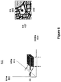
[0073] WASN用のユーザ・インターフェースは、そのリソースのユーザ制御、およびその結果の表示を設けることができる。上の4つのデータ次元は、2つの形式で表示することができる。第1の形式は、図5において、ある範囲の経度および緯度の位置、時間スライダによって示される特定の時間、ならびに周波数および帯域幅スライダによって示される特定の周波数および帯域幅における電力の輪郭プロットとして示されている。他方の形式は、時間および周波数対電力の3−Dプロットであり、図6に示すように、2Dの位置が、ある範囲の経度および緯度においてカーソルを位置付けることによって定められる。
・ Time ・ Frequency
・ Power ・ Position
[0073] A user interface for the WASN may provide user control of the resource and display of the results. The top four data dimensions can be displayed in two forms. The first form is shown in FIG. 5 as a contour plot of power at a range of longitude and latitude positions, a specific time indicated by the time slider, and a specific frequency and bandwidth indicated by the frequency and bandwidth slider. Has been. The other form is a 3-D plot of time and frequency versus power, where a 2D position is defined by positioning the cursor at a range of longitude and latitude, as shown in FIG.
[0074] 図5は、ユーザ・インターフェースおよびWASNの一例を示す。図示するのは、キャンペーン例を表示するユーザ・インターフェースのスクリーンショット例501である。3−Dマップ501が、発信元の位置を、位置検出プロセッサによって決定された緯度503軸および経度502軸によって表示し、更に試験対象帯域幅において計算した絶対放射電力503を表示する。試験対象帯域幅506が、バー・ディスプレイ505上に示されている。試験対象帯域幅の中心周波数508が、周波数バー・ディスプレイ507上に示されている。スペクトル試験の時間は、時間バー509上において選択することができる。
[0074] FIG. 5 shows an example of a user interface and WASN. Shown is a
[0075] この例におけるユーザ・インターフェース500は、入力および出力双方を供給し、WASNのデータベース機能を用いて、経時的な信号および位置データを格納する。各バー・ディスプレイによって、ユーザは、マウス駆動式ポイント・アンド・クリック・インターフェース(point-and-click interface)を用いて、調節可能な帯域幅、中心周波数、および時間範囲に対して、信号電力および位置を判定することができる。
[0075] The
[0076] 図6は、他のグラフィカル・ユーザ・インタースの一例を示す。ここでは、電力602、時間603、および周波数604の三次元マップ601が用いられており、ここでは、地理的マップが二次元街路マップとして示されている。位置判定は、高度(altitude)即ち高さ(elevation)を含んでもよい。永続的データベースを用いて信号および位置情報を格納することにより、ユーザ・インターフェースは、リアル・タイムのキャンペーン、ならびに過去の位置検出および信号データの双方を示すために用いることができる。
アプリケーション
[0077] アプリケーションは、システム・コントローラ/中央プロセッサに存在し、複数の動作を実行するWASNの能力を装備することができる。WASNアプリケーションは、次のものを含むことができる。
干渉検出および位置判定
[0078] 干渉検出および位置判定(location)アプリケーションは、WASNのユーザ定義重要帯域、チャネル、および周波数を監視する能力を利用して、「干渉」として定められる不正信号の存在を検出する。正規信号の先験的特性を利用して、干渉を検出する際の補助とする。一旦干渉が検出されると、この干渉の位置を判定する。干渉検出および位置判定キャンペーンの結果は、データベースに格納され、および/またはユーザ・インターフェース上に表示される。
信号調査
[0079] 信号調査アプリケーションは、WASNの信号検出能力を利用して、WASNの配備エリア全域における全ての信号の特性および位置を判定する。信号調査キャンペーンの結果は、データベースに格納され、および/またはユーザ・インターフェース上に表示される。
不正送信機検出および位置判定
[0080] 不正送信機アプリケーションは、信号調査キャンペーンの出力を、正規信号のリストと比較して、不正である可能性がある送信機を特定する。
スプーファ検出(Spoofer Detection)
[0081] なりすまし信号(spoofing signal)とは、一人以上のユーザを混乱させるためまたは騙すために、有効な信号のように偽装しようとする信号のことである。例えば、なりすましグローバル・ナビゲーション衛星システム(GNSS)信号は、受信機がいない場所にいると判定するように、GNSS受信機を騙す。WASNは、なりすまし信号を捕獲し特徴化することによって、なりすまし信号を検出し、その位置を突き止める。なりすまし信号の特性が適法信号(1つまたは複数)の特性と比較され、WASNは著しい逸脱があるときに注意する。なりすましGNSS信号の例を用いると、この信号の絶対電力レベルを判定することができ、これが適法のGNSS信号よりも遙かに高い場合、この信号はなりすまし信号として特定される。なりすましGNSS信号を特定する他の方法は、現在利用できない衛星(例えば、水平上(over-the-horizon))によって受信信号が特定されたと判定することである。このGNSSシステムの例は、米国NavStar汎地球測位システム(GPS)である。
スペクトル利用
[0082] スペクトル利用アプリケーションは、かなりの時間長にわたって、検出された信号から送信を監視して、RFエネルギが送信されている時間の百分率を判定する。これによって、百分率占有メトリック(percentage occupancy metric)が得られる。加えて、RFエネルギが送信されている時間の百分率は、この特定の送信機が提供する地理的カバレッジを定量化する。スペクトル利用キャンペーンの結果は、データベースに格納され、および/またはユーザ・インターフェース上に表示される。
無許諾「ホワイト・スペース」送信機の電力および配置(placement)
[0083] 無許諾「ホワイト・スペース」アプリケーションは、WASNの信号検出能力を利用して、ディジタルTV送信機を特定しその位置を突き止め、更に送信機の送信電力を推定する。この情報を用いて、WASNは、当該WASNの地理的エリアにおける正規および許諾ディジタルTV送信機と干渉することなく、「ホワイト・スペース」送信機が送信できる電力レベルを判定する。
代表例−GNSSジャマー(jammer)検出および位置判定
[0084] この代表的な一例では、地理的に分散された広域ソフトウェア受信機のネットワークを有する位置測定ユニット(LMU)ネットワークと共に配備されたワイヤレス位置検出システムが用いられる。更に、グローバル・ナビゲーション衛星システム(1つまたは複数)(GNSS)は、米国NavaStar汎地球測位システム(GPS)として記載される。他のGNSSシステム(Galileo、GLONASS、Compass等)、または複数のGNSSシステムからの衛星の組み合わせも、GPSシステムと共に、またはその代わりに用いることができる。
[0076] FIG. 6 shows an example of another graphical user interface. Here, a three-
application
[0077] The application resides in the system controller / central processor and can be equipped with WASN's ability to perform multiple operations. The WASN application can include:
Interference detection and position determination
[0078] Interference detection and location applications detect the presence of fraudulent signals, defined as "interference", utilizing the ability to monitor WASN user-defined critical bands, channels, and frequencies. Use a priori characteristics of the normal signal to assist in detecting interference. Once interference is detected, the position of this interference is determined. Interference detection and location campaign results are stored in a database and / or displayed on the user interface.
Signal survey
[0079] The signal survey application uses the signal detection capabilities of the WASN to determine the characteristics and location of all signals throughout the WASN deployment area. The results of the signal survey campaign are stored in a database and / or displayed on the user interface.
Unauthorized transmitter detection and position determination
[0080] The unauthorized transmitter application compares the output of the signal survey campaign with a list of legitimate signals to identify transmitters that may be unauthorized.
Spoofer detection
[0081] A spoofing signal is a signal that attempts to disguise like a valid signal to confuse or deceive one or more users. For example, a spoofed global navigation satellite system (GNSS) signal tricks a GNSS receiver to determine that it is in a location where there is no receiver. The WASN detects and locates the spoofed signal by capturing and characterizing the spoofed signal. The characteristic of the spoofed signal is compared to the characteristic of the legitimate signal (s) and the WASN notes that there is a significant deviation. Using the example of a spoofed GNSS signal, the absolute power level of this signal can be determined, and if it is much higher than a legal GNSS signal, this signal is identified as a spoofed signal. Another way to identify the spoofed GNSS signal is to determine that the received signal has been specified by a satellite that is not currently available (eg, over-the-horizon). An example of this GNSS system is the US NavStar Global Positioning System (GPS).
Use of spectrum
[0082] The spectrum utilization application monitors the transmission from the detected signal for a significant length of time to determine the percentage of time that RF energy is being transmitted. This provides a percent occupancy metric. In addition, the percentage of time that RF energy is being transmitted quantifies the geographic coverage that this particular transmitter provides. The results of the spectrum usage campaign are stored in a database and / or displayed on the user interface.
Unlicensed “white space” transmitter power and placement
[0083] The unlicensed “white space” application uses the signal detection capabilities of WASN to locate and locate the digital TV transmitter and further estimate the transmitter's transmit power. With this information, the WASN determines the power level that the “white space” transmitter can transmit without interfering with regular and licensed digital TV transmitters in the geographical area of the WASN.
Representative example-GNSS jammer detection and position determination
[0084] In this representative example, a wireless location system is used that is deployed with a location unit (LMU) network having a network of geographically distributed wide area software receivers. In addition, the Global Navigation Satellite System (s) (GNSS) is described as the US NavaStar Global Positioning System (GPS). Other GNSS systems (Galileo, GLONASS, Compass, etc.) or combinations of satellites from multiple GNSS systems can also be used with or instead of the GPS system.
[0085] 現在のLMUには、アップリンクおよびダウンリンク位置判定用に別個の広域受信機、ならびに共通クロック基準を受信するためのGPS受信機が装備されている。LMUネットワーク自体は、低電力PGSジャマーから比較的保護されており、ジャマーを検出および位置判定するのに理想的な状況にある。LMU GPS受信機は、通常、最小の近隣妨害(nearby obstruction)で設置され、近隣構造よりも高い高度に設置されるのが理想的である。 [0085] Current LMUs are equipped with separate wide area receivers for uplink and downlink position determination and a GPS receiver for receiving a common clock reference. The LMU network itself is relatively protected from low power PGS jammers and is in an ideal situation for detecting and locating jammers. LMU GPS receivers are typically installed with minimal near obstruction and ideally installed at higher altitudes than neighboring structures.
[0086] PGS広域CDMA信号は、弱く、極軌道にある宇宙船から放射する。野外にあるGPS受信機のアンテナでは、GPS信号強度は、130から160dbmの範囲、または約1×10-16ワットである。用いられる波長を考えると、地上および回りの構造物からの反射はなおも一層減衰する。各衛星を追跡し用いる能力を決定するのは、信号電力の単位帯域幅当たりのノイズ電力に対する比率である。したがって、GPSジャマー(意図しないものであっても)は、通例、広域ホワイト/グレー・ノイズを送信してローカル・ノイズ・フロアーを高くし、こうしてあらゆるローカルGPS受信機を混乱させる。ジャマーを突き止めるためには、問題は、最初にジャマー(1つまたは複数)を検出し、第2にジャマーの位置を判定することである。 [0086] The PGS wide area CDMA signal is weak and radiates from a spacecraft in polar orbit. For an outdoor GPS receiver antenna, the GPS signal strength is in the range of 130 to 160 dbm, or about 1 × 10 −16 watts. Given the wavelengths used, reflections from ground and surrounding structures are still more attenuated. It is the ratio of signal power to noise power per unit bandwidth that determines the ability to track and use each satellite. Thus, GPS jammers (even those that are not intended) typically transmit wide-area white / grey noise to raise the local noise floor, thus confusing any local GPS receiver. To locate the jammer, the problem is to first detect the jammer (s) and secondly determine the position of the jammer.
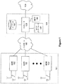
[0087] 図7に示すように、ワイヤレス通信システム701は、地理的サービス・エリア全域にカバレッジを設けるように分散されたセルを備えている。通信ネットワーク用の無線機器は、セル・サイト704に収容されており、SDR受信機と一緒に配置されて、SDRネットワークに、地理的分散および共有設備ならびにアンテナ・マウントを設ける。GNSSシステム(この例では、GPSシステム)が、705において、関連する無線ブロードキャストと共に示されている。
[0087] As shown in FIG. 7, the
[0088] GPSジャマー702は、送信電力および地面クラッタ(ground clutter)によって決定されるエリア703を伝搬する妨害無線信号を送信する。また、伝搬パターン703は、指向性送信アンテナによって形状を決めることもできる。
[0088] The GPS jammer 702 transmits an interfering radio signal that propagates in an
[0089] 既知の方法を用いて、GPS受信サブシステムは、妨害の存在を検出し、外部に警告することができる。このような妨害は、1つのLMUまたはLMUのグループに制限することができる。知られている非軍事用GNSSジャマーは、数十メートルから数十キロメートルの範囲を有するが、比較的電力が少ない携帯用デバイスである可能性が高い。 [0089] Using known methods, the GPS receiving subsystem can detect the presence of disturbances and alert the outside. Such interference can be limited to one LMU or group of LMUs. Known non-military GNSS jammers have a range of tens of meters to tens of kilometers, but are likely to be portable devices with relatively low power.
[0090] 意図的または意図的でないGNSS妨害のソースを検出するために、LMUは可視PGS衛星の1回の完全なサイクルの間、ベースライン信号対ノイズ比(SNR)を維持することができる。閾値のSNRが交差されたときに、ジャマー位置検出イベントを開始することができる。 [0090] To detect a source of intentional or unintentional GNSS interference, the LMU can maintain a baseline signal-to-noise ratio (SNR) for one complete cycle of the visible PGS satellite. A jammer position detection event can be initiated when the threshold SNR is crossed.
[0091] 小型および/または低電力GNSSジャマーに対して、送信電力、RF環境、および信号の期間に応じて、到達時間(TOA)または到達電力(POA)に基づく測距、あるいはTDOAまたはAOAというような技法によって、このGNSSジャマーの位置を判定することができる。現在のLMU GPS受信アンテナに対する変更、またはGPS受信機の広域SDRとの交換を用いて、GPSジャマー受信機を可能にしてもよい。大規模なGNSS妨害イベントに対しては、影響を受けたLMUをプロットすることができ、LMUカバレッジ・エリアの重力の中心を、ジャマーの位置として判定することができる。LMUは、暫定的なTOAまたはPOAに基づく位置検出に基づいて、TDOAおよび/またはAOA位置判定に合わせて選択することができる。更に、配備された位置検出技術、ならびに妨害信号(1つまたは複数)の電力および帯域幅に基づいて、ジャマーの位置を更に精度高く提示するように、LMUを選択することもできる。 [0091] For small and / or low power GNSS jammers, ranging based on time of arrival (TOA) or power of arrival (POA), or TDOA or AOA, depending on transmit power, RF environment, and signal duration The position of this GNSS jammer can be determined by such a technique. The GPS jammer receiver may be enabled using a change to the current LMU GPS receive antenna or replacement of the GPS receiver with a wide area SDR. For large GNSS jamming events, the affected LMU can be plotted and the center of gravity of the LMU coverage area can be determined as the position of the jammer. The LMU can be selected for TDOA and / or AOA position determination based on provisional TOA or POA based position detection. In addition, the LMU can be selected to more accurately present the position of the jammer based on the deployed location technology and the power and bandwidth of the jamming signal (s).
[0092] LMUがジャマーの近くに位置しそのGPS信号を失った場合、このLMUを協同装置(cooperator)として用いることができなくても、ジャマーが送信した基準信号を収集するために、このLMUをなおも用いることができる可能性がある。粗いタイミングのためのネットワークからのタイミングまたはメッセージング用のダウンリンク・ビーコン監視を用いると、基準信号を収集し、圧縮し、正しいタイミング基準を有する協同LMUに配信することができる。 [0092] If the LMU is located near the jammer and loses its GPS signal, this LMU can be used to collect the reference signal transmitted by the jammer, even if the LMU cannot be used as a cooperator. Could still be used. With timing from the network for coarse timing or downlink beacon monitoring for messaging, the reference signal can be collected, compressed and delivered to the collaborative LMU with the correct timing reference.
[0093] 一般的なコール位置判定では、基準信号を検出し復調するために高精度のタイミングを有していないLMUを用いる技法であっても、用いることができる。このようなLMUは、そのタイミングが位置検出処理のためには十分な精度ではないので、協同装置としては用いられない。しかしながら、ダウンリンク監視および/またはネットワーク・タイミングによって、ジャマーが送信した基準信号の検出および復調には、このLMUを用いることができる。 In general call position determination, even a technique that uses an LMU that does not have high-precision timing to detect and demodulate a reference signal can be used. Such an LMU is not used as a cooperative device because its timing is not accurate enough for position detection processing. However, this LMU can be used to detect and demodulate the reference signal transmitted by the jammer due to downlink monitoring and / or network timing.
[0094] GNSS妨害ソースを突き止める場合、TDOAまたはAOA位置検出を実行するとよい。GNSS妨害信号が、変化しつつあり常にオンであるタイプのノイズ・ソースであると仮定すると、LMUまたは同様のデバイスは、この信号のサンプルを特定の時間間隔で収集することができる。このデータは、圧縮され、協同LMUに送られて、相関付けを行い位置を判定することができる。 [0094] When locating a GNSS interference source, TDOA or AOA location detection may be performed. Assuming that the GNSS jamming signal is a changing and always on type of noise source, the LMU or similar device can collect samples of this signal at specific time intervals. This data can be compressed and sent to the collaborative LMU to correlate and determine location.
[0095] システムが突き止めた妨害ソースが明瞭なトーンまたは一連のトーンであり、経時的に変化していない場合、協同LMUの全てにおけるそのベースラインSNRからのGPS信号のSNRの変化を用いて、影響を受ける各LMUサイトにおけるSNRの電力レベル影響に基づいて、TDOA位置を計算するプロセスと同様に、位置を計算することができる。到達時間差の代わりに、妨害信号の電力勾配(POAまたはPDOA)を用いることもできる。
代表的例−GNSSスプーファ検出および位置判定
[0096] 他の代表的な例では、本開示にしたがってGNSSスプーファを突き止めるために、地理的に分散されたLMUネットワーク、ならびにこれと一緒に配置された広域およびGPS受信機を用いることができる。
[0095] If the disturbance source that the system has located is a clear tone or series of tones that have not changed over time, then using the change in SNR of the GPS signal from its baseline SNR in all of the cooperative LMUs, Based on the SNR power level impact at each affected LMU site, a location can be calculated similar to the process of calculating the TDOA location. Instead of the arrival time difference, the power gradient of the jamming signal (POA or PDOA) can also be used.
Representative example-GNSS spoofer detection and position determination
[0096] In another representative example, a geographically distributed LMU network and wide area and GPS receivers deployed therewith can be used to locate a GNSS spoofer in accordance with the present disclosure.
[0097] GNSSなりすましには、通例より高い電力であり、受信機の高さで宇宙船によって配信されるGNSS衛星送信を偽装する送信機が関与するのが一般的である。場合によっては、受信機の視野にない宇宙船(例えば、水平線上)の識別情報を用いて、なりすましのために宇宙船を模擬することもできる。 [0097] GNSS spoofing typically involves a transmitter that disguises a GNSS satellite transmission that is typically higher power and delivered by a spacecraft at the height of the receiver. In some cases, the spacecraft (eg, on the horizon) that is not in the field of view of the receiver can be used to simulate the spacecraft for impersonation.
[0098] スプーファがGNSS衛星送信を偽装しているとき、受信機が分散されているネットワークは、なりすまし信号の信号電力増大によって、なりすまし送信機を検出することができる。 [0098] When the spoofer is impersonating a GNSS satellite transmission, the network in which the receivers are distributed can detect the spoofed transmitter by increasing the signal power of the spoofed signal.
[0099] 受信機の視野内にない宇宙船の識別情報を用いて宇宙船を偽装する場合、軌道力学のために利用可能であると予測されない衛星の追加を検出することができる。 [0099] If a spacecraft is camouflaged using spacecraft identification information that is not within the field of view of the receiver, the addition of satellites that are not expected to be available for orbital mechanics can be detected.
[0100] 両方の場合、PDOA、TOA、TDOA、またはハイブリッド技法によってなりすまし送信機の位置を判定するために、広域なりすまし信号を用いることができる。
代表例−IMSIキャッチャ(catcher)検出
[0101] 本願と同じ譲受人に譲渡された米国特許出願第11/948,244号”Autonomous Configuration of a Wireless Location System”(ワイヤレス位置検出システムの自律構成)に記載されているように、LMUネットワークの広域ダウンリンク受信機を用いて、基地局ビーコン送信によって、GSM、CDMA、CDMA−2000、およびUMTSワイヤレス通信システムを検出し、特定し、位置を判定することができる。この特許出願をここで引用したことにより、その内容全体が本願にも含まれるものとする。この自律構成の出願では、新たな基地局を判定することがだけでなく、基地局識別や周波数割り当ての変更も判定することができる。
[0100] In both cases, a wide-area spoofing signal can be used to determine the location of the spoofing transmitter by PDOA, TOA, TDOA, or hybrid techniques.
Typical example-IMSI catcher detection
[0101] LMU network as described in US Patent Application No. 11 / 948,244 "Autonomous Configuration of a Wireless Location System" assigned to the same assignee as the present application. GSM, CDMA, CDMA-2000, and UMTS wireless communication systems can be detected, identified, and located by base station beacon transmission using a wide area downlink receiver. This patent application is hereby incorporated by reference in its entirety. In this autonomous configuration application, not only a new base station can be determined, but also a change in base station identification and frequency assignment can be determined.
[0102] 不良基地送受信局(BTS)(IMSI−キャッチャとも呼ぶ)について、ヨーロッパ特許EP1051053、”Method for identifying a mobile phone user or for eavesdropping on outgoing calls”(移動体電話機ユーザを特定するまたは出立コールにおいて盗み聞きする方法)、および米国特許出願第11/966,230号、”Acquiring Identity Parameters by Emulating Base Stations”(基地局をエミュレートすることによる識別パラメータの取得)に記載されている。記載されているように、不良BTSは、既に存在する基地局に属するビーコンを送信することによって、ワイヤレス・ネットワークをシミュレートし、ローカル・ワイヤレス通信ネットワークに属する基地局に偽装する。地理的に分散された受信機のLMUネットワークの検出、特定、および位置判定能力を用いて、更にサービング移動体位置検出センタ(SMLC)をコントローラとして用いて、二重偽装(duplicative mimicked)基地局ビーコンを検出し、特定し、位置を判定することができる。 [0102] For bad base transceiver station (BTS) (also called IMSI-Catcher), European Patent EP1051053, "Method for identifying a mobile phone user or for eavesdropping on outgoing calls" In US patent application Ser. No. 11 / 966,230, “Acquiring Identity Parameters by Emulating Base Stations”. As described, a bad BTS simulates a wireless network by transmitting a beacon belonging to an already existing base station and impersonates a base station belonging to the local wireless communication network. Duplicative mimicked base station beacons using the geographically distributed receiver LMU network detection, identification and location capabilities, and also using a serving mobile location center (SMLC) as a controller Can be detected, identified, and position determined.
[0103] 図8は、本開示による分散ネットワーク・ベースIMSI−キャッチャ不正BTS位置検出装置(locator)の一例を示す。低電力のIMSI−キャッチャが、ローカル・ビーコン807、808、809において、電力、識別、および近隣リストを含む情報を収集する。IMSI−キャッチャ802は、次いで、それ自体の偽装ビーコンをブロードキャストする。この偽装ビーコンは地理的エリア803全域に伝搬する。対象の移動体/ユーザ機器801は、IMSI−キャッチャがエミュレートしたネットワークに対して、位置更新を行う。
[0103] FIG. 8 illustrates an example of a distributed network based IMSI-catcher rogue BTS locator according to this disclosure. A low power IMSI-catcher collects information including power, identification, and neighbor list in
[0104] この例におけるSDR受信機は、近郊(close)セル804、近隣(neighboring)セル805、および近接(proximate)セル806全てに配置されている(collocate)。過去において近郊セル806、近隣セル805、および近接セル806を既に検出、特定、および位置判定し、格納してあれば、SDR受信機は、偽装ビーコン803を検出し、不良BTSを特定することができる。SDRネットワークは、不良BTSを突き止めるように同調され、不良BTSに関する情報が、分析および処置のために、ユーザ・インターフェースに配信される。
[0104] The SDR receiver in this example is arranged in all of the
[0105] 図9aにおいて、WASNの使用例を示す。この例では、センサ受信機901、902、903が、ワイヤレス通信またはブロードキャスト・システムが担当する地理的エリアに分散されている。異なる(disparate)時点において、干渉信号904、905、906が検出され、位置が判定される。図9bは、結果的に得られたユーザ・インターフェースの表示を示す。マップ表示907上において、干渉信号904、905、906のソースが、地理的に、908、909、910に表示されている。干渉の時刻および期間が、時間バー表示911上に表示され、干渉イベント904、905、906が、図式的に912、913、914として示されている。スペクトル・バー915は、イベント904について周波数に対する電力の分布を表示する。羅針図916の表示が薄くなり(gray out)、イベント904について方位が得られないことを示す。速度インディケータ917は、ゼロの速度を示し、羅針図と共に、イベント904が時間期間912にわたって静止していたことを示す。
D.結論
[0106] 以上に述べた態様は、そのいずれもが、方法、システム、コンピュータ読み取り可能媒体、または任意のタイプの製造物で実現することができる。回路(circuitry)という用語は、本開示において用いられる場合、特殊ハードウェア・コンポーネントを含むことができる。同じ実施形態または他の実施形態において、回路は、ファームウェアまたはスイッチによって機能(1つまたは複数)を実行するように構成されたマイクロプロセッサを含むことができる。同じ実施形態例または他の実施形態例において、回路は、1つ以上の汎用処理ユニットおよび/またはマルチコア処理ユニット等を含むことができ、これらは、機能(1つまたは複数)を実行するように動作可能なロジックを具体化するソフトウェア命令がメモリ、例えば、RAMおよび/または仮想メモリにロードされたときに構成することができる。回路がハードウェアおよびソフトウェアの組み合わせを含む実施形態例では、実施者(implementer)は、ロジックを具体化するソース・コードを書くことができ、このソース・コードをコンパイルしてマシン読み取り可能コードとし、汎用処理ユニット(1つまたは複数)によって処理することができる。
[0105] In Fig. 9a, a usage example of WASN is shown. In this example,
D. Conclusion
[0106] Any of the aspects described above can be implemented in a method, system, computer-readable medium, or any type of product. The term circuit, when used in this disclosure, can include special hardware components. In the same or other embodiments, the circuit can include a microprocessor configured to perform the function (s) by firmware or a switch. In the same example embodiment or other example embodiments, the circuit may include one or more general purpose processing units and / or multi-core processing units, etc., that perform the function (s). Software instructions that embody operable logic can be configured when loaded into memory, eg, RAM and / or virtual memory. In an example embodiment where the circuit includes a combination of hardware and software, an implementer can write source code that embodies the logic and compiles the source code into machine-readable code, It can be processed by general-purpose processing unit (s).
[0107] 図1は、本開示の態様を実現するように構成することができる計算システムの一例を示す。この計算システムは、コンピュータ20等を含むことができる。コンピュータ20は、処理ユニット21、システム・メモリ22、およびシステム・メモリを含む種々のシステム・コンポーネントを処理ユニット21に結合するシステム・バス23を含む。システム・バス23は、メモリ・バスまたはメモリ・コントローラ、周辺バス、および種々のバス・アーキテクチャのうち任意のものを用いたローカル・バスを含む様々なタイプのバス構造のうち任意のものとすることができる。システム・メモリは、リード・オンリ・メモリ(ROM)24およびランダム・アクセス・メモリ(RAM)25を含む。基本入/出力システム26(BIOS)は、起動中のように、コンピュータ20内のエレメント間におけるデータ伝送を補助する基本的なルーティンを含み、通例ROM24内に格納されている。更に、コンピュータ20は、図示しないハード・ディスクからの読み取りおよびこれへの書き込みを行うハード・ディスク・ドライブ27、リムーバブル磁気ディスク29からの読み取りおよびこれへの書き込みを行う磁気ディスク・ドライブ28、およびCDROMまたは他の光媒体のようなリムーバブル光ディスク31からの読み取りおよびこれへの書き込みを行う光ディスク・ドライブ30も含むことができる。実施形態例によっては、本発明の態様を具体化するコンピュータ実行可能命令をROM24、ハード・ディスク(図示せず)、RAM25、リムーバブル磁気ディスク29、光ディスク31、および/または処理ユニット21のキャッシュに格納することができる。ハード・ディスク・ドライブ27、磁気ディスク・ドライブ28、および光ディスク・ドライブ30は、それぞれ、ハード・ディスク・ドライブ・インターフェース32、磁気ディスク・ドライブ・インターフェース33、および光ドライブ・インターフェース34によって、システム・バス23に接続されている。これらのドライブおよびそれらと関連のあるコンピュータ読み取り可能媒体は、コンピュータ読み取り可能命令、データ構造、プログラム・モジュール、およびコンピュータ20の他のデータの不揮発性記憶に備える。本明細書において記載する環境はハード・ディスク、リムーバブル磁気ディスク29、およびリムーバブル光ディスク31を採用するが、磁気カセット、フラッシュ・メモリ・カード、ディジタル・ビデオ・ディスク、ベルヌーイ・カートリッジ、ランダム・アクセス・メモリ(RAM)、リード・オンリ・メモリ(ROM)等のような、コンピュータによってアクセス可能なデータを格納することができる他のタイプのコンピュータ読み取り可能媒体も、この動作環境において用いてもよいことは、当業者には認められてしかるべきである。
[0107] FIG. 1 illustrates an example of a computing system that can be configured to implement aspects of the present disclosure. This computing system can include a computer 20 or the like. The computer 20 includes a
[0108] ハード・ディスク、磁気ディスク29、光ディスク31、ROM24、またはRAM25には、複数のプログラム・モジュールを格納することができ、その中には、オペレーティング・システム35、1つ以上のアプリケーション・プログラム36、その他のプログラム・モジュール37、およびプログラム・データー38を含む。ユーザは、キーボード40のような入力デバイス、およびポインティング・デバイス42によって、コマンドおよび情報をコンピュータ20に入力することができる。他の入力デバイス(図示せず)には、マイクロフォン、ジョイスティック、ゲーム・パッド、衛星ディスク、スキャナ等を含むことができる。これらおよびその他の入力デバイスは、多くの場合、シリアル・ポート・インターフェース46を介して、処理ユニット21に接続されている。シリアル・ポート・インターフェース46は、システム・バスに結合されているが、パラレル・ポート、ゲーム・ポート、またはユニバーサル・シリアル・バス(USB)のようなその他のインターフェースによって接続することも可能である。ディスプレイ47またはその他の形式のディスプレイ・デバイスも、ビデオ・アダプタ48のようなインターフェースおよびケーブル57を介して、システム・バス23に接続されている。ディスプレイ47に加えて、コンピュータは、スピーカおよびプリンタのような、その他の周辺出力装置(図示せず)も含むことができる。また、図1のシステムは、ホスト・アダプタ55、スモール・コンピュータ・システム・インターフェース(SCSI)バス56、およびこのSCSIバス56に接続されている外部記憶デバイス62も含む。
[0108] A plurality of program modules can be stored in the hard disk, magnetic disk 29, optical disk 31, ROM 24, or
[0109] コンピュータ20は、リモート・コンピュータ49のような1つ以上のリモート・コンピュータへの論理接続を用いて、ネットワーク環境において動作することも可能である。リモート・コンピュータ49は、他のコンピュータ、サーバ、ルータ、ネットワークPC、ピアデバイス、またはその他の共通ネットワーク・ノードとすることができ、通例、コンピュータ20に関して先に説明したエレメントの多くまたは全てを含むが、図1にはメモリ記憶装置50のみを示す。図1に示す論理接続は、ローカル・エリア・ネットワーク(LAN)51およびワイド・エリア・ネットワーク(WAN)52を含む。このようなネットワーク環境は、事務所、企業規模のコンピューター・ネットワーク、イントラネットおよびインターネットにおいては、一般的である。
Computer 20 may also operate in a network environment using logical connections to one or more remote computers, such as
[0110] LANネットワーク環境で用いる場合、コンピュータ20は、ネットワーク・インターフェースまたはアダプタ53を介してLAN51に接続される。WANネットワーク環境で用いる場合、コンピュータ20は、通例、モデム54、またはインターネットのようなワイド・エリア・ネットワーク52を通じて通信を設定するその他の手段を含む。モデム54は、内蔵でも外付けでもよく、シリアル・ポート・インターフェース46を介してシステム・バス23に接続することができる。ネットワーク接続環境では、コンピュータ20に関して図示したプログラム・モジュール、またはその一部を、リモート・メモリ記憶装置に格納することもできる。尚、図示のネットワーク接続は一例であり、コンピュータ間で通信リンクを確立する他の手段も使用可能であることは認められよう。更に、本発明の複数の実施形態はコンピュータ・システムに特に適しているが、本文書においては、本開示をこのような実施形態に限定することを意図するものはない。
When used in a LAN network environment, the computer 20 is connected to the
[0111] 以上の詳細な説明は、例および/または動作図を通じて、システムおよび/またはプロセスの種々の実施形態を明記した。このようなブロック図および/または例が1つ以上の機能および/または動作を含む限りにおいて、このようなブロック図または例の中にある各機能および/または動作は、個々におよび/または集合的に、広範囲のハードウェア、ソフトウェア、ファームウェア、または事実上そのあらゆる組み合わせによって実現できることは、当業者には言うまでもないであろう。 [0111] The foregoing detailed description has specified various embodiments of the systems and / or processes through examples and / or operational diagrams. As long as such block diagrams and / or examples include one or more functions and / or operations, each function and / or operation in such block diagrams or examples may be individually and / or collectively It will be appreciated by those skilled in the art that a wide range of hardware, software, firmware, or virtually any combination thereof can be implemented.
[0112] 本明細書に記載した発明の特定の態様および実施形態を示しそして説明したが、本明細書における教示に基づいて、変更および修正(changes and modifications)を行うこともでき、したがって、添付した特許請求の範囲は、本明細書において記載した発明の真の主旨および範囲に該当するのであれば、そのような変更および修正の全てをその範囲の中に包含することは、当業者には明白であろう。 [0112] While particular aspects and embodiments of the invention described herein have been shown and described, changes and modifications may be made based on the teachings herein and, therefore, attached If the appended claims fall within the true spirit and scope of the invention described herein, those skilled in the art will recognize that all such changes and modifications are included in the scope. It will be obvious.
Claims (102)
RF信号情報の履歴データベースを維持するステップであって、前記RF信号情報が、前記広域ワイヤレス通信ネットワークの中にある複数の位置において所定の期間所定の帯域幅にわたって前記1つ以上のソフトウェア定義無線機によって受信されたRF信号を表す、ステップと、
干渉側RF信号の存在を検出するステップと、
前記干渉側RF信号の受信電力を特徴化するステップと、
前記干渉側RF信号の帯域幅を判定するステップと、
ネットワーク・ベース・ワイヤレス位置検出技法によって、前記干渉側RF信号のソースの位置を判定するステップと、
を含む、方法。 A method for detecting, classifying, and determining a location of a radio frequency (RF) transmitter in a wide area wireless communication network including one or more software defined radios, comprising:
Maintaining a history database of RF signal information, wherein the RF signal information is the one or more software defined radios over a predetermined bandwidth for a predetermined period of time at a plurality of locations in the wide area wireless communication network. Representing the RF signal received by:
Detecting the presence of an interfering RF signal;
Characterizing the received power of the interfering RF signal;
Determining the bandwidth of the interfering RF signal;
Determining the location of the source of the interfering RF signal by a network-based wireless location technique;
Including a method.
監視すべき信号に対応する時間ドメインRFデータを受信するステップであって、前記RFデータが、所定の期間において所定の帯域幅にわたる前記信号を表す、ステップと、
前記受信した時間ドメインRFデータを、前記所定の期間にわたる複数の等しい時間間隔と関連付けるステップと、
前記等しい時間間隔と関連付けられた時間ドメインRFデータを、複数の周波数ビンに対応する周波数ドメイン・データに変換するステップと、
前記周波数ビンの各々について、そして前記監視すべき少なくとも1つの信号について、少なくとも1つの電力特性を判定するステップと、
前記周波数ビンの各々について、当該周波数ビンについての前記少なくとも1つの電力特性が、前記監視すべき信号の少なくとも1つの電力特性とは実質的に異なるときに、干渉ソースがあると判定するステップと、
ジオロケーション判定アルゴリズムを用いて、前記干渉ソースの位置を判定するステップと、
を含む、方法。 A method of detecting, classifying and determining a location of radio frequency (RF) comprising:
Receiving time domain RF data corresponding to a signal to be monitored, wherein the RF data represents the signal over a predetermined bandwidth in a predetermined time period;
Associating the received time domain RF data with a plurality of equal time intervals over the predetermined period of time;
Transforming time domain RF data associated with the equal time intervals into frequency domain data corresponding to a plurality of frequency bins;
Determining at least one power characteristic for each of the frequency bins and for the at least one signal to be monitored;
Determining for each of the frequency bins that there is an interference source when the at least one power characteristic for the frequency bin is substantially different from the at least one power characteristic of the signal to be monitored;
Determining the position of the interference source using a geolocation determination algorithm;
Including a method.
監視すべき信号に対応する時間ドメインRFデータを受信するステップであって、前記RFデータが、所定の期間および所定の帯域幅にわたる前記信号を表す、ステップと、
前記受信した時間ドメインRFデータを、前記所定の期間にわたる複数の等しい時間間隔と関連付けるステップと、
前記等しい時間間隔と関連付けられた前記時間ドメインRFデータを、複数の周波数ビンに対応する周波数ドメイン・データに変換するステップと、
前記周波数ビンの各々について、そして前記監視すべき少なくとも1つの信号について、少なくとも1つの電力特性を判定するステップと、
少なくとも1つの電力特性がノイズ・フロアーよりも高い周波数ビンを特定するステップと、
少なくとも1つの電力特性が前記ノイズ・フロアーよりも高いと特定された周波数ビンの各々について、当該周波数ビンにおける信号を特徴化するステップと、
ジオロケーション判定アルゴリズムを用いて、前記特徴化した信号の位置を判定するステップと、
を含む、方法。 A method for detecting, classifying, and determining a location of a radio frequency (RF) transmitter in a wide area wireless communication network including one or more software defined radios, comprising:
Receiving time domain RF data corresponding to a signal to be monitored, wherein the RF data represents the signal over a predetermined period of time and a predetermined bandwidth;
Associating the received time domain RF data with a plurality of equal time intervals over the predetermined period of time;
Converting the time domain RF data associated with the equal time intervals into frequency domain data corresponding to a plurality of frequency bins;
Determining at least one power characteristic for each of the frequency bins and for the at least one signal to be monitored;
Identifying a frequency bin whose at least one power characteristic is higher than the noise floor;
For each frequency bin identified as having at least one power characteristic higher than the noise floor, characterizing the signal in that frequency bin;
Determining a position of the characterized signal using a geolocation determination algorithm;
Including a method.
監視すべき信号に対応する時間ドメインRFデータを受信するステップであって、前記RFデータが、所定の期間において所定の帯域幅にわたる前記信号を表す、ステップと、
前記受信した時間ドメインRFデータを、前記所定の期間にわたる複数の等しい時間間隔と関連付けるステップと、
前記等しい時間間隔と関連付けられた時間ドメインRFデータを、複数の周波数ビンに対応する周波数ドメイン・データに変換するステップと、
前記周波数ビンの各々について、そして前記監視すべき少なくとも1つの信号について、少なくとも1つの電力特性を判定するステップと、
前記周波数ビンの各々について、当該周波数ビンについての前記少なくとも1つの電力特性が、前記監視すべき信号の少なくとも1つの電力特性とは実質的に異なるときに、干渉ソースがあると判定するステップと、
ジオロケーション判定アルゴリズムを用いて、前記干渉ソースの位置を判定するステップと、
を含む、システム。 A system for detecting, classifying, and determining a radio frequency (RF) transmitter in a wide area wireless communication network, the system including one or more software defined radios having a wide instantaneous bandwidth and tuning range At least one processor communicatively coupled to the one or more software defined radios and at least one memory communicatively coupled to the at least one processor, the at least one memory Storing computer readable instructions capable of configuring the system to perform the method, the method comprising:
Receiving time domain RF data corresponding to a signal to be monitored, wherein the RF data represents the signal over a predetermined bandwidth in a predetermined time period;
Associating the received time domain RF data with a plurality of equal time intervals over the predetermined period of time;
Transforming time domain RF data associated with the equal time intervals into frequency domain data corresponding to a plurality of frequency bins;
Determining at least one power characteristic for each of the frequency bins and for the at least one signal to be monitored;
Determining for each of the frequency bins that there is an interference source when the at least one power characteristic for the frequency bin is substantially different from the at least one power characteristic of the signal to be monitored;
Determining the position of the interference source using a geolocation determination algorithm;
Including the system.
監視すべき信号に対応する時間ドメインRFデータを受信するステップであって、前記RFデータが、所定の期間および所定の帯域幅にわたる前記信号を表す、ステップと、
前記受信した時間ドメインRFデータを、前記所定の期間にわたる複数の等しい時間間隔と関連付けるステップと、
前記等しい時間間隔と関連付けられた前記時間ドメインRFデータを、複数の周波数ビンに対応する周波数ドメイン・データに変換するステップと、
前記周波数ビンの各々および前記監視すべき少なくとも1つの信号について、少なくとも1つの電力特性を判定するステップと、
少なくとも1つの電力特性がノイズ・フロアーよりも高い周波数ビンを特定するステップと、
少なくとも1つの電力特性が前記ノイズ・フロアーよりも高いと特定された周波数ビンの各々について、当該周波数ビンにおける信号を特徴化するステップと、
ジオロケーション判定アルゴリズムを用いて、前記特徴化した信号の位置を判定するステップと、
を含む、システム。 A system for detecting, classifying, and determining a radio frequency (RF) transmitter in a wide area wireless communication network, the system including one or more software defined radios having a wide instantaneous bandwidth and tuning range At least one processor communicatively coupled to the one or more software defined radios and at least one memory communicatively coupled to the at least one processor, the at least one memory Storing computer readable instructions capable of configuring the system to perform the method, the method comprising:
Receiving time domain RF data corresponding to a signal to be monitored, wherein the RF data represents the signal over a predetermined period of time and a predetermined bandwidth;
Associating the received time domain RF data with a plurality of equal time intervals over the predetermined period of time;
Converting the time domain RF data associated with the equal time intervals into frequency domain data corresponding to a plurality of frequency bins;
Determining at least one power characteristic for each of said frequency bins and said at least one signal to be monitored;
Identifying a frequency bin whose at least one power characteristic is higher than the noise floor;
For each frequency bin identified as having at least one power characteristic higher than the noise floor, characterizing the signal in that frequency bin;
Determining a position of the characterized signal using a geolocation determination algorithm;
Including the system.
Applications Claiming Priority (3)
| Application Number | Priority Date | Filing Date | Title |
|---|---|---|---|
| US12/346,598 | 2008-12-30 | ||
| US12/346,598 US8138975B2 (en) | 2008-12-30 | 2008-12-30 | Interference detection, characterization and location in a wireless communications or broadcast system |
| PCT/US2009/067772 WO2010077790A1 (en) | 2008-12-30 | 2009-12-11 | Interference detection, characterization and location in a wireless communications or broadcast system |
Publications (2)
| Publication Number | Publication Date |
|---|---|
| JP2012514209A true JP2012514209A (en) | 2012-06-21 |
| JP2012514209A5 JP2012514209A5 (en) | 2012-12-27 |
Family
ID=42310129
Family Applications (1)
| Application Number | Title | Priority Date | Filing Date |
|---|---|---|---|
| JP2011544457A Pending JP2012514209A (en) | 2008-12-30 | 2009-12-11 | Interference detection, characterization, and location determination in wireless communications or broadcast systems |
Country Status (11)
| Country | Link |
|---|---|
| US (2) | US8138975B2 (en) |
| EP (1) | EP2384447A4 (en) |
| JP (1) | JP2012514209A (en) |
| KR (1) | KR20110116022A (en) |
| CN (1) | CN102272617B (en) |
| AU (1) | AU2009333383B2 (en) |
| BR (1) | BRPI0923888A2 (en) |
| CA (1) | CA2746269C (en) |
| IL (1) | IL213317A (en) |
| MX (1) | MX2011006512A (en) |
| WO (1) | WO2010077790A1 (en) |
Cited By (5)
| Publication number | Priority date | Publication date | Assignee | Title |
|---|---|---|---|---|
| JP2015031696A (en) * | 2013-08-01 | 2015-02-16 | テクトロニクス・インコーポレイテッドTektronix,Inc. | Automated spectrum monitoring system |
| JP2015056802A (en) * | 2013-09-12 | 2015-03-23 | 株式会社東芝 | Monitoring system |
| JP2019531460A (en) * | 2016-09-13 | 2019-10-31 | レグルス・サイバー・リミテッドRegulus Cyber Ltd. | System and method for identifying global navigation satellite system impersonation attacks on protective transport machinery |
| JP7364654B2 (en) | 2021-12-08 | 2023-10-18 | アンリツ株式会社 | Radio interference monitoring device and radio interference monitoring method |
| JP7364655B2 (en) | 2021-12-08 | 2023-10-18 | アンリツ株式会社 | Radio interference monitoring device and radio interference monitoring method |
Families Citing this family (115)
| Publication number | Priority date | Publication date | Assignee | Title |
|---|---|---|---|---|
| US6807405B1 (en) | 1999-04-28 | 2004-10-19 | Isco International, Inc. | Method and a device for maintaining the performance quality of a code-division multiple access system in the presence of narrow band interference |
| US8103293B2 (en) | 2006-10-17 | 2012-01-24 | Itt Manufacturing Enterprises, Inc. | System and related circuits and methods for detecting and locating wireless communication device use within a geographical area or facility |
| US8385483B2 (en) | 2008-11-11 | 2013-02-26 | Isco International, Llc | Self-adaptive digital RF bandpass and bandstop filter architecture |
| US8138975B2 (en) * | 2008-12-30 | 2012-03-20 | Trueposition, Inc. | Interference detection, characterization and location in a wireless communications or broadcast system |
| US8521028B2 (en) * | 2009-03-22 | 2013-08-27 | Universite Laval | Method and system for high precision GPS applications |
| US8971441B2 (en) * | 2009-06-08 | 2015-03-03 | Lawrence Livermore National Security, Llc | Transmit-reference methods in software defined radio platforms for communication in harsh propagation environments and systems thereof |
| DE102009026124A1 (en) * | 2009-07-07 | 2011-01-13 | Elan Schaltelemente Gmbh & Co. Kg | Method and system for acquisition, transmission and evaluation of safety-related signals |
| US9584350B1 (en) * | 2009-08-14 | 2017-02-28 | Liberty University | Electronic jamming system and method |
| CA2693012C (en) * | 2009-09-18 | 2015-06-23 | Her Majesty The Queen In Right Of Canada As Represented By The Ministeof National Defence | Signal detection in fading environments |
| US8340588B2 (en) * | 2009-09-18 | 2012-12-25 | Her Majesty The Queen In Right Of Canada As Represented By The Minister Of National Defence | Handheld synthetic antenna array |
| US8340578B2 (en) * | 2009-10-05 | 2012-12-25 | Apple Inc. | Methods and apparatus for enhanced coexistence algorithms in wireless systems |
| EP2553836A4 (en) * | 2010-03-28 | 2017-05-17 | LG Electronics Inc. | Method and apparatus of transmitting a white space map information in a wireless local area network system |
| US8526974B2 (en) * | 2010-04-12 | 2013-09-03 | Telefonaktiebolaget L M Ericsson (Publ) | Locating a source of wireless transmissions from a licensed user of a licensed spectral resource |
| US8364090B2 (en) * | 2010-04-15 | 2013-01-29 | Apple Inc. | Method and apparatus for wireless radio frequency test signal generation |
| CA2811890C (en) * | 2010-09-27 | 2016-07-05 | Lg Electronics Inc. | Method and apparatus of transmitting a white space map information in a wireless local area network system |
| US8599709B2 (en) | 2011-02-10 | 2013-12-03 | Apple Inc. | Methods and apparatus for wireless coexistence based on transceiver chain emphasis |
| DE102011106591B4 (en) * | 2011-06-16 | 2015-05-13 | Astrium Gmbh | Method and system for determining the position of a GNSS receiver mounted in a motor vehicle |
| US8995902B2 (en) * | 2011-08-12 | 2015-03-31 | Bae Systems Information And Electronic System Integration Inc. | Link 16-based geolocation of hostile jammers |
| CN102419428A (en) * | 2011-09-13 | 2012-04-18 | 国网电力科学研究院 | Integral calibrating method of radio interference measuring device |
| US9658314B2 (en) | 2012-03-02 | 2017-05-23 | Nokomis, Inc. | System and method for geo-locating and detecting source of electromagnetic emissions |
| JP6608276B2 (en) * | 2012-05-14 | 2019-11-20 | ザ・ボーイング・カンパニー | Context-based virtual data boundaries |
| US9185516B2 (en) | 2012-05-21 | 2015-11-10 | Qualcomm Incorporated | Radio frequency interference awareness assistance data |
| WO2014020604A1 (en) * | 2012-07-31 | 2014-02-06 | Inuitive Ltd. | Multiple sensors processing system for natural user interface applications |
| KR101221978B1 (en) * | 2012-09-03 | 2013-01-15 | 한국항공우주연구원 | Localization method of multiple jammers based on tdoa method |
| US9733338B1 (en) | 2012-10-08 | 2017-08-15 | The Boeing Company | Single satellite geolocation systems and methods |
| US20140145882A1 (en) * | 2012-10-08 | 2014-05-29 | The Boeing Company | Geolocation systems and methods |
| KR101240629B1 (en) * | 2012-11-30 | 2013-03-11 | 한국항공우주연구원 | Detecting and localization method of unknown signal using aircraft with ads-b system |
| US9819441B2 (en) * | 2013-01-21 | 2017-11-14 | Spectrum Effect, Inc. | Method for uplink jammer detection and avoidance in long-term evolution (LTE) networks |
| US10231206B2 (en) | 2013-03-15 | 2019-03-12 | DGS Global Systems, Inc. | Systems, methods, and devices for electronic spectrum management for identifying signal-emitting devices |
| US10257728B2 (en) | 2013-03-15 | 2019-04-09 | DGS Global Systems, Inc. | Systems, methods, and devices for electronic spectrum management |
| US10237770B2 (en) | 2013-03-15 | 2019-03-19 | DGS Global Systems, Inc. | Systems, methods, and devices having databases and automated reports for electronic spectrum management |
| US10257729B2 (en) | 2013-03-15 | 2019-04-09 | DGS Global Systems, Inc. | Systems, methods, and devices having databases for electronic spectrum management |
| US10122479B2 (en) | 2017-01-23 | 2018-11-06 | DGS Global Systems, Inc. | Systems, methods, and devices for automatic signal detection with temporal feature extraction within a spectrum |
| US10244504B2 (en) | 2013-03-15 | 2019-03-26 | DGS Global Systems, Inc. | Systems, methods, and devices for geolocation with deployable large scale arrays |
| US10451706B1 (en) * | 2013-03-15 | 2019-10-22 | Wiser Systems, Inc. | Methods and systems for selecting the shortest path in a multi-path environment |
| US8750156B1 (en) | 2013-03-15 | 2014-06-10 | DGS Global Systems, Inc. | Systems, methods, and devices for electronic spectrum management for identifying open space |
| US9537586B2 (en) * | 2013-03-15 | 2017-01-03 | DGS Global Systems, Inc. | Systems, methods, and devices for electronic spectrum management with remote access to data in a virtual computing network |
| US10219163B2 (en) | 2013-03-15 | 2019-02-26 | DGS Global Systems, Inc. | Systems, methods, and devices for electronic spectrum management |
| US10257727B2 (en) | 2013-03-15 | 2019-04-09 | DGS Global Systems, Inc. | Systems methods, and devices having databases and automated reports for electronic spectrum management |
| US11646918B2 (en) | 2013-03-15 | 2023-05-09 | Digital Global Systems, Inc. | Systems, methods, and devices for electronic spectrum management for identifying open space |
| US9319916B2 (en) | 2013-03-15 | 2016-04-19 | Isco International, Llc | Method and appartus for signal interference processing |
| US9622041B2 (en) | 2013-03-15 | 2017-04-11 | DGS Global Systems, Inc. | Systems, methods, and devices for electronic spectrum management |
| US10271233B2 (en) | 2013-03-15 | 2019-04-23 | DGS Global Systems, Inc. | Systems, methods, and devices for automatic signal detection with temporal feature extraction within a spectrum |
| US10223139B2 (en) * | 2013-03-15 | 2019-03-05 | The Trustees Of The University Of Pennsylvania | Dynamically deployable wireless infrastructure in cloud environment |
| US10299149B2 (en) | 2013-03-15 | 2019-05-21 | DGS Global Systems, Inc. | Systems, methods, and devices for electronic spectrum management |
| US20150092574A1 (en) * | 2013-09-30 | 2015-04-02 | Fluke Corporation | Detecting the presence of rogue femtocells in enterprise networks |
| WO2015065664A1 (en) * | 2013-10-30 | 2015-05-07 | Javad Gnss, Inc. | Interference map for gnss device |
| KR101446445B1 (en) * | 2013-12-06 | 2014-10-06 | 한국항공우주연구원 | Position estimating device and method for estimating position of radio wave source |
| US9551778B2 (en) * | 2014-01-07 | 2017-01-24 | Novatel Inc. | GNSS jammer detection system with optical tracking and identification |
| US9775116B2 (en) | 2014-05-05 | 2017-09-26 | Isco International, Llc | Method and apparatus for increasing performance of communication links of cooperative communication nodes |
| US9766343B2 (en) | 2014-06-19 | 2017-09-19 | Novatel Inc. | System and method for determining location of an interfering signal source |
| US9612296B2 (en) * | 2014-10-08 | 2017-04-04 | Qualcomm Incorporated | Methods and apparatus for testing of wireless power transmitters and systems |
| RU2669700C1 (en) * | 2015-02-09 | 2018-10-15 | КОНСЕНТРИК РИАЛ ТАЙМ, ЭлЭлСи | Radio receiver for detecting signal source location |
| EP3651386B1 (en) | 2015-05-04 | 2023-08-23 | ISCO International, LLC | Method and apparatus for increasing the performance of communication paths for communication nodes |
| GB201511200D0 (en) * | 2015-06-25 | 2015-08-12 | Airspan Networks Inc | Steerable antenna system |
| GB2539731B (en) | 2015-06-25 | 2021-08-04 | Airspan Ip Holdco Llc | Quality of service in wireless backhauls |
| GB2539734A (en) | 2015-06-25 | 2016-12-28 | Airspan Networks Inc | An antenna apparatus and method of performing spatial nulling within the antenna apparatus |
| GB2539730B (en) | 2015-06-25 | 2021-04-07 | Airspan Ip Holdco Llc | Node role assignment in networks |
| GB2539736A (en) | 2015-06-25 | 2016-12-28 | Airspan Networks Inc | Wireless network configuration using path loss determination between nodes |
| GB2539733A (en) | 2015-06-25 | 2016-12-28 | Airspan Networks Inc | An antenna apparatus and method of configuring a transmission beam for the antenna apparatus |
| GB2539735A (en) | 2015-06-25 | 2016-12-28 | Airspan Networks Inc | Sub-sampling antenna elements |
| CN107787595B (en) | 2015-06-25 | 2021-07-13 | 艾尔斯潘网络公司 | Managing external interference in a wireless network |
| GB2539727B (en) | 2015-06-25 | 2021-05-12 | Airspan Ip Holdco Llc | A configurable antenna and method of operating such a configurable antenna |
| GB2539732A (en) | 2015-06-25 | 2016-12-28 | Airspan Networks Inc | A configurable antenna and method of operating such a configurable antenna |
| GB2539722B (en) | 2015-06-25 | 2021-10-13 | Airspan Ip Holdco Llc | Bearing calculation |
| US9743231B2 (en) | 2015-08-25 | 2017-08-22 | Verint Systems Ltd. | System and method for using multiple networks to estimate a location of a mobile communication terminal |
| US20170245361A1 (en) * | 2016-01-06 | 2017-08-24 | Nokomis, Inc. | Electronic device and methods to customize electronic device electromagnetic emissions |
| KR102497723B1 (en) * | 2016-01-21 | 2023-02-09 | 삼성전자주식회사 | A Method For Detecting The Location based Wireless Interference And User Terminal Using The Same |
| US9723588B1 (en) | 2016-03-28 | 2017-08-01 | Google Inc. | Determining a location of a wireless transmitter |
| US10230743B1 (en) | 2016-05-12 | 2019-03-12 | Wells Fargo Bank, N.A. | Rogue endpoint detection |
| US10652835B2 (en) | 2016-06-01 | 2020-05-12 | Isco International, Llc | Signal conditioning to mitigate interference impacting wireless communication links in radio access networks |
| WO2018029648A1 (en) * | 2016-08-12 | 2018-02-15 | Telefonaktiebolaget Lm Ericsson (Publ) | Detecting network jamming |
| US10444887B2 (en) | 2016-09-20 | 2019-10-15 | Cypress Semiconductor Corporation | Force sensing |
| CN106535217B (en) * | 2016-12-15 | 2020-02-28 | 中铁二院工程集团有限责任公司 | GSM-R interference source fusion positioning method based on GDOP analysis |
| US10529241B2 (en) | 2017-01-23 | 2020-01-07 | Digital Global Systems, Inc. | Unmanned vehicle recognition and threat management |
| US10459020B2 (en) | 2017-01-23 | 2019-10-29 | DGS Global Systems, Inc. | Systems, methods, and devices for automatic signal detection based on power distribution by frequency over time within a spectrum |
| US10498951B2 (en) | 2017-01-23 | 2019-12-03 | Digital Global Systems, Inc. | Systems, methods, and devices for unmanned vehicle detection |
| US10700794B2 (en) | 2017-01-23 | 2020-06-30 | Digital Global Systems, Inc. | Systems, methods, and devices for automatic signal detection based on power distribution by frequency over time within an electromagnetic spectrum |
| US10422846B2 (en) * | 2017-01-30 | 2019-09-24 | Rohde & Schwarz Gmbh & Co. Kg | Method for calibrating a radio frequency test instrument and radio frequency test instrument |
| US10448864B1 (en) | 2017-02-24 | 2019-10-22 | Nokomis, Inc. | Apparatus and method to identify and measure gas concentrations |
| US10481236B2 (en) | 2017-03-15 | 2019-11-19 | Cypress Semiconductor Corporation | Systems and methods for estimating angle of arrival in a wireless device |
| CN107996031B (en) * | 2017-04-01 | 2022-03-11 | 达闼机器人有限公司 | Data transmission method, resource scheduling method, device, terminal and network side equipment |
| US10298279B2 (en) | 2017-04-05 | 2019-05-21 | Isco International, Llc | Method and apparatus for increasing performance of communication paths for communication nodes |
| EP3385745B1 (en) * | 2017-04-06 | 2021-03-03 | Volvo Car Corporation | Method and system for determining the position of a user device in relation to a vehicle |
| CN107064683B (en) * | 2017-04-20 | 2020-12-25 | 捷开通讯(深圳)有限公司 | Interference detection device |
| KR102019875B1 (en) * | 2017-04-25 | 2019-09-09 | 국방과학연구소 | Pulse tracking system |
| US10461791B2 (en) | 2017-05-03 | 2019-10-29 | Telefonaktiebolaget Lm Ericsson (Publ) | Interference analysis in wireless networks |
| US10812121B2 (en) | 2017-08-09 | 2020-10-20 | Isco International, Llc | Method and apparatus for detecting and analyzing passive intermodulation interference in a communication system |
| US10284313B2 (en) | 2017-08-09 | 2019-05-07 | Isco International, Llc | Method and apparatus for monitoring, detecting, testing, diagnosing and/or mitigating interference in a communication system |
| US10983220B2 (en) * | 2017-11-20 | 2021-04-20 | Javad Gnss, Inc. | Spoofing detection and rejection |
| US11280912B2 (en) | 2018-01-12 | 2022-03-22 | The Regents Of The University Of Colorado | Hybrid interference localization |
| FR3077141B1 (en) * | 2018-01-22 | 2020-07-03 | Kerlink | METHOD FOR GEOLOCATING A SIGNAL TRANSMITTING DEVICE |
| US11489847B1 (en) | 2018-02-14 | 2022-11-01 | Nokomis, Inc. | System and method for physically detecting, identifying, and diagnosing medical electronic devices connectable to a network |
| EP3763145B1 (en) | 2018-03-07 | 2022-09-07 | Smartsky Networks Llc | 3d spectrum measurement and mapping |
| US10972191B2 (en) * | 2018-05-22 | 2021-04-06 | Asia Satellite Telecommunications Company Limited | Uplink interference geolocation method and system for high throughput satellite |
| US10943461B2 (en) | 2018-08-24 | 2021-03-09 | Digital Global Systems, Inc. | Systems, methods, and devices for automatic signal detection based on power distribution by frequency over time |
| KR102249544B1 (en) | 2018-09-14 | 2021-06-18 | 주식회사 에버플러스 | System for detecting use of mobile terminal |
| KR102580505B1 (en) * | 2018-09-17 | 2023-09-21 | 삼성전자주식회사 | Display apparatus, method for controlling thereof and recording media thereof |
| KR102162284B1 (en) * | 2018-10-26 | 2020-10-06 | 인하대학교 산학협력단 | Cloud data processing gnss jamming monitoring method and system |
| GB2578922B (en) | 2018-11-14 | 2023-06-28 | Ge Aviat Systems Ltd | Detecting the spoofing of a signal |
| CN111190195B (en) * | 2018-11-14 | 2024-04-30 | 中兴通讯股份有限公司 | Method, device and system for detecting pseudo GNSS interference |
| CN109557562B (en) * | 2018-12-03 | 2023-03-31 | 中国电波传播研究所(中国电子科技集团公司第二十二研究所) | GNSS interference source positioning method based on radio wave propagation model |
| EP3690472B1 (en) * | 2019-01-30 | 2021-10-20 | Rohde & Schwarz GmbH & Co. KG | Method as well as device for timeslot-wise detection of at least one radio signal |
| US11269078B1 (en) * | 2019-01-30 | 2022-03-08 | Architecture Technology Corporation | Systems and methods for detecting global positioning system spoofing signal emitters |
| CN112152696B (en) * | 2019-06-29 | 2022-10-28 | 亚洲卫星有限公司 | Uplink interference geographic positioning method and system for high-throughput satellite |
| US11082853B2 (en) * | 2019-08-07 | 2021-08-03 | At&T Intellectual Property I, L.P. | System and method for avoiding signal spoofing attacks in wireless broadband networks |
| CN110944317A (en) * | 2019-11-28 | 2020-03-31 | 南京森林警察学院 | Method for realizing mobile digital communication equipment characteristic discovery and identification |
| CN111654902B (en) * | 2020-06-02 | 2024-01-19 | Tcl通讯(宁波)有限公司 | Method and device for reducing GPS signal interference of mobile terminal and mobile terminal |
| CN111830537B (en) * | 2020-06-11 | 2024-03-12 | 北京睿锋科技有限公司 | GPS tracking module detection method and device, electronic equipment and storage medium |
| US11177852B1 (en) * | 2020-09-22 | 2021-11-16 | Bae Systems Information And Electronic Systems Integration Inc. | Digital detection and tracking of signals over multiple frequency bins |
| DE102020212033A1 (en) * | 2020-09-24 | 2022-03-24 | Robert Bosch Gesellschaft mit beschränkter Haftung | Procedure for detecting a manipulated or forged GNSS signal |
| CN112651349B (en) * | 2020-12-30 | 2022-01-07 | 西南交通大学 | Wireless interference detection method, device, equipment and readable storage medium |
| US11381266B1 (en) * | 2020-12-31 | 2022-07-05 | Iridium Satellite Llc | Wireless communication with interference mitigation |
| CN114476061B (en) * | 2021-12-24 | 2024-02-09 | 中国电信股份有限公司 | Interference positioning method and unmanned aerial vehicle |
| FR3140182A1 (en) * | 2022-09-27 | 2024-03-29 | Safran Electronics & Defense | Method of assisting the landing of an aircraft |
Citations (5)
| Publication number | Priority date | Publication date | Assignee | Title |
|---|---|---|---|---|
| JP2005142750A (en) * | 2003-11-05 | 2005-06-02 | Motorola Inc | Method and system for specifying location |
| JP2006524472A (en) * | 2003-04-15 | 2006-10-26 | トゥルーポジション・インコーポレーテッド | Multipath location processor |
| JP2007013500A (en) * | 2005-06-29 | 2007-01-18 | Canon Inc | Radio terminal position estimating system, position estimating method for radio terminal position estimating system, and data processor |
| WO2008036676A2 (en) * | 2006-09-21 | 2008-03-27 | Trueposition, Inc. | Location quality of service indicator |
| JP2008107280A (en) * | 2006-10-27 | 2008-05-08 | Mitsubishi Electric Corp | Radar device |
Family Cites Families (32)
| Publication number | Priority date | Publication date | Assignee | Title |
|---|---|---|---|---|
| US4720712A (en) * | 1985-08-12 | 1988-01-19 | Raytheon Company | Adaptive beam forming apparatus |
| US4728959A (en) | 1986-08-08 | 1988-03-01 | Ventana Sciences Inc. | Direction finding localization system |
| US5327144A (en) | 1993-05-07 | 1994-07-05 | Associated Rt, Inc. | Cellular telephone location system |
| US5510801A (en) | 1994-03-01 | 1996-04-23 | Stanford Telecommunications, Inc. | Location determination system and method using television broadcast signals |
| US5828336A (en) | 1996-03-29 | 1998-10-27 | The United States Of America As Represented By The Administrator Of The National Aeronautics And Space Administration | Robust real-time wide-area differential GPS navigation |
| US6047192A (en) | 1996-05-13 | 2000-04-04 | Ksi Inc. | Robust, efficient, localization system |
| US6108555A (en) | 1996-05-17 | 2000-08-22 | Ksi, Inc. | Enchanced time difference localization system |
| US5936571A (en) | 1997-01-31 | 1999-08-10 | Lockheed Martin Corporation | Integrated GPS/interference location system |
| US6184829B1 (en) | 1999-01-08 | 2001-02-06 | Trueposition, Inc. | Calibration for wireless location system |
| DE19920222C5 (en) | 1999-05-03 | 2017-03-02 | Rohde & Schwarz Gmbh & Co. Kg | Method and arrangement for identifying the user of a mobile telephone or for monitoring the outgoing calls |
| US6522297B1 (en) | 2001-02-02 | 2003-02-18 | Rosum Corporation | Position location using ghost canceling reference television signals |
| US6559800B2 (en) | 2001-02-02 | 2003-05-06 | Rosum Corporation | Position location using broadcast analog television signals |
| US6876859B2 (en) | 2001-07-18 | 2005-04-05 | Trueposition, Inc. | Method for estimating TDOA and FDOA in a wireless location system |
| US6917328B2 (en) | 2001-11-13 | 2005-07-12 | Rosum Corporation | Radio frequency device for receiving TV signals and GPS satellite signals and performing positioning |
| US7424268B2 (en) * | 2002-04-22 | 2008-09-09 | Cisco Technology, Inc. | System and method for management of a shared frequency band |
| US7026987B2 (en) | 2004-02-10 | 2006-04-11 | Thales Navigation, Inc. | Asynchronous assisted GPS position determination |
| US7339525B2 (en) | 2004-07-30 | 2008-03-04 | Novariant, Inc. | Land-based local ranging signal methods and systems |
| US20060234641A1 (en) * | 2005-02-03 | 2006-10-19 | Lucent Technologies Inc. | System for using an existing cellular network to detect incidents of GPS jaming |
| US7095368B1 (en) | 2005-03-18 | 2006-08-22 | Global Locate, Inc. | Method and apparatus for combining measurements and determining clock offsets between different satellite positioning systems |
| ES2323598T3 (en) | 2005-07-22 | 2009-07-21 | M.M.I. Research Limited | ACQUISITION OF IDENTITY PARAMETERS EMULATING BASE STATIONS. |
| US7471241B1 (en) | 2005-07-25 | 2008-12-30 | Chun Yang | Global navigation satellite system (GNSS) receivers based on satellite signal channel impulse response |
| US7280810B2 (en) | 2005-08-03 | 2007-10-09 | Kamilo Feher | Multimode communication system |
| US7593738B2 (en) | 2005-12-29 | 2009-09-22 | Trueposition, Inc. | GPS synchronization for wireless communications stations |
| US7471236B1 (en) | 2006-03-01 | 2008-12-30 | Telecommunication Systems, Inc. | Cellular augmented radar/laser detector |
| US7511662B2 (en) | 2006-04-28 | 2009-03-31 | Loctronix Corporation | System and method for positioning in configured environments |
| WO2007039320A2 (en) * | 2006-12-20 | 2007-04-12 | Phonak Ag | Hearing assistance system and method of operating the same |
| US7551126B2 (en) | 2007-03-08 | 2009-06-23 | Trimble Navigation Limited | GNSS sample processor for determining the location of an event |
| US20080252518A1 (en) | 2007-03-21 | 2008-10-16 | Yerachmiel Yeshayahu | Method and apparatus for determining location using a hybrid solution |
| WO2008151057A2 (en) | 2007-05-31 | 2008-12-11 | Sr Telecom Inc. | Method of detecting sources of interference in a wireless communication system |
| US8548488B2 (en) | 2007-11-30 | 2013-10-01 | Trueposition, Inc. | Automated configuration of a wireless location system |
| US8436768B2 (en) | 2008-12-30 | 2013-05-07 | Trueposition, Inc. | Diversity time and frequency location receiver |
| US8138975B2 (en) * | 2008-12-30 | 2012-03-20 | Trueposition, Inc. | Interference detection, characterization and location in a wireless communications or broadcast system |
-
2008
- 2008-12-30 US US12/346,598 patent/US8138975B2/en active Active
-
2009
- 2009-12-11 CA CA2746269A patent/CA2746269C/en not_active Expired - Fee Related
- 2009-12-11 KR KR1020117017861A patent/KR20110116022A/en not_active Application Discontinuation
- 2009-12-11 CN CN2009801531306A patent/CN102272617B/en not_active Expired - Fee Related
- 2009-12-11 JP JP2011544457A patent/JP2012514209A/en active Pending
- 2009-12-11 MX MX2011006512A patent/MX2011006512A/en active IP Right Grant
- 2009-12-11 BR BRPI0923888-3A patent/BRPI0923888A2/en not_active IP Right Cessation
- 2009-12-11 AU AU2009333383A patent/AU2009333383B2/en not_active Ceased
- 2009-12-11 EP EP09836793.1A patent/EP2384447A4/en not_active Withdrawn
- 2009-12-11 WO PCT/US2009/067772 patent/WO2010077790A1/en active Application Filing
-
2011
- 2011-06-02 IL IL213317A patent/IL213317A/en not_active IP Right Cessation
-
2012
- 2012-02-28 US US13/407,224 patent/US9121923B2/en active Active
Patent Citations (5)
| Publication number | Priority date | Publication date | Assignee | Title |
|---|---|---|---|---|
| JP2006524472A (en) * | 2003-04-15 | 2006-10-26 | トゥルーポジション・インコーポレーテッド | Multipath location processor |
| JP2005142750A (en) * | 2003-11-05 | 2005-06-02 | Motorola Inc | Method and system for specifying location |
| JP2007013500A (en) * | 2005-06-29 | 2007-01-18 | Canon Inc | Radio terminal position estimating system, position estimating method for radio terminal position estimating system, and data processor |
| WO2008036676A2 (en) * | 2006-09-21 | 2008-03-27 | Trueposition, Inc. | Location quality of service indicator |
| JP2008107280A (en) * | 2006-10-27 | 2008-05-08 | Mitsubishi Electric Corp | Radar device |
Cited By (6)
| Publication number | Priority date | Publication date | Assignee | Title |
|---|---|---|---|---|
| JP2015031696A (en) * | 2013-08-01 | 2015-02-16 | テクトロニクス・インコーポレイテッドTektronix,Inc. | Automated spectrum monitoring system |
| JP2015056802A (en) * | 2013-09-12 | 2015-03-23 | 株式会社東芝 | Monitoring system |
| JP2019531460A (en) * | 2016-09-13 | 2019-10-31 | レグルス・サイバー・リミテッドRegulus Cyber Ltd. | System and method for identifying global navigation satellite system impersonation attacks on protective transport machinery |
| US11460586B2 (en) | 2016-09-13 | 2022-10-04 | Regulus Cyber Ltd. | System and method for identifying global navigation satellite system spoofing attacks on a protected vehicle |
| JP7364654B2 (en) | 2021-12-08 | 2023-10-18 | アンリツ株式会社 | Radio interference monitoring device and radio interference monitoring method |
| JP7364655B2 (en) | 2021-12-08 | 2023-10-18 | アンリツ株式会社 | Radio interference monitoring device and radio interference monitoring method |
Also Published As
| Publication number | Publication date |
|---|---|
| CN102272617A (en) | 2011-12-07 |
| US20120032854A1 (en) | 2012-02-09 |
| US8138975B2 (en) | 2012-03-20 |
| BRPI0923888A2 (en) | 2018-05-29 |
| CN102272617B (en) | 2013-02-27 |
| US9121923B2 (en) | 2015-09-01 |
| KR20110116022A (en) | 2011-10-24 |
| IL213317A (en) | 2016-05-31 |
| MX2011006512A (en) | 2011-07-12 |
| CA2746269C (en) | 2015-08-04 |
| US20120154213A1 (en) | 2012-06-21 |
| EP2384447A4 (en) | 2014-07-09 |
| AU2009333383A1 (en) | 2010-07-08 |
| AU2009333383B2 (en) | 2013-05-09 |
| CA2746269A1 (en) | 2010-07-08 |
| WO2010077790A1 (en) | 2010-07-08 |
| EP2384447A1 (en) | 2011-11-09 |
| IL213317A0 (en) | 2011-07-31 |
Similar Documents
| Publication | Publication Date | Title |
|---|---|---|
| US9121923B2 (en) | Interference detection, characterization and location in a wireless communications or broadcast system | |
| JP5468135B2 (en) | Diversity time and frequency location receiver | |
| US8810452B2 (en) | Network location and synchronization of peer sensor stations in a wireless geolocation network | |
| CN115398274A (en) | SPS spoofing detection | |
| AU2010239592A1 (en) | Network autonomous wireless location system | |
| Maeng et al. | Impact of 3D antenna radiation pattern in UAV air-to-ground path loss modeling and RSRP-based localization in rural area | |
| US10764718B1 (en) | System and method for obtaining radio frequency (RF) signal data | |
| Horsmanheimo et al. | Location-aided planning in mobile network—trial results | |
| Shakir et al. | Measurement-based geolocation in LTE cellular networks | |
| WO2002063329A1 (en) | User positioning | |
| US20050176443A1 (en) | Cellular phone geolocation system | |
| Balaei | Detection, characterization and mitigation of interference in receivers for global navigation satellite systems | |
| WO2018166626A1 (en) | Radio-based object detection | |
| Poberezhskiy et al. | An Experimental Receiver for Positioning by Triangulating on Non-Cooperating Cell Towers | |
| Maeng et al. | Kriging-Based 3-D Spectrum Awareness for Radio Dynamic Zones Using Aerial Spectrum Sensors | |
| Dagefu et al. | Low VHF channel measurements and simulations in indoor and outdoor scenarios | |
| Masiukiewicz | The methods of users localization in 802.11 networks | |
| Andam-Arkoful et al. | Evaluation of ultra wide-band for indoor positioning | |
| Tabatabaei Balaei | Detection, characterization and mitigation of interference in receivers for global navigation satellite systems |
Legal Events
| Date | Code | Title | Description |
|---|---|---|---|
| RD02 | Notification of acceptance of power of attorney |
Free format text: JAPANESE INTERMEDIATE CODE: A7422 Effective date: 20120712 |
|
| RD04 | Notification of resignation of power of attorney |
Free format text: JAPANESE INTERMEDIATE CODE: A7424 Effective date: 20120726 |
|
| A521 | Request for written amendment filed |
Free format text: JAPANESE INTERMEDIATE CODE: A523 Effective date: 20121108 |
|
| A621 | Written request for application examination |
Free format text: JAPANESE INTERMEDIATE CODE: A621 Effective date: 20121108 |
|
| A977 | Report on retrieval |
Free format text: JAPANESE INTERMEDIATE CODE: A971007 Effective date: 20140129 |
|
| A131 | Notification of reasons for refusal |
Free format text: JAPANESE INTERMEDIATE CODE: A131 Effective date: 20140204 |
|
| A601 | Written request for extension of time |
Free format text: JAPANESE INTERMEDIATE CODE: A601 Effective date: 20140507 |
|
| A602 | Written permission of extension of time |
Free format text: JAPANESE INTERMEDIATE CODE: A602 Effective date: 20140514 |
|
| A521 | Request for written amendment filed |
Free format text: JAPANESE INTERMEDIATE CODE: A523 Effective date: 20140603 |
|
| A131 | Notification of reasons for refusal |
Free format text: JAPANESE INTERMEDIATE CODE: A131 Effective date: 20150106 |
|
| A02 | Decision of refusal |
Free format text: JAPANESE INTERMEDIATE CODE: A02 Effective date: 20150602 |