JP2012508380A - Apparatus and method for providing a full Jones matrix based analysis for determining depolarization polarization parameters using optical frequency domain imaging - Google Patents
Apparatus and method for providing a full Jones matrix based analysis for determining depolarization polarization parameters using optical frequency domain imaging Download PDFInfo
- Publication number
- JP2012508380A JP2012508380A JP2011535668A JP2011535668A JP2012508380A JP 2012508380 A JP2012508380 A JP 2012508380A JP 2011535668 A JP2011535668 A JP 2011535668A JP 2011535668 A JP2011535668 A JP 2011535668A JP 2012508380 A JP2012508380 A JP 2012508380A
- Authority
- JP
- Japan
- Prior art keywords
- radiation
- sample
- configuration
- polarization
- characteristic
- Prior art date
- Legal status (The legal status is an assumption and is not a legal conclusion. Google has not performed a legal analysis and makes no representation as to the accuracy of the status listed.)
- Pending
Links
Images
Classifications
-
- G—PHYSICS
- G01—MEASURING; TESTING
- G01B—MEASURING LENGTH, THICKNESS OR SIMILAR LINEAR DIMENSIONS; MEASURING ANGLES; MEASURING AREAS; MEASURING IRREGULARITIES OF SURFACES OR CONTOURS
- G01B9/00—Measuring instruments characterised by the use of optical techniques
- G01B9/02—Interferometers
- G01B9/02001—Interferometers characterised by controlling or generating intrinsic radiation properties
- G01B9/02002—Interferometers characterised by controlling or generating intrinsic radiation properties using two or more frequencies
- G01B9/02004—Interferometers characterised by controlling or generating intrinsic radiation properties using two or more frequencies using frequency scans
-
- A—HUMAN NECESSITIES
- A61—MEDICAL OR VETERINARY SCIENCE; HYGIENE
- A61B—DIAGNOSIS; SURGERY; IDENTIFICATION
- A61B5/00—Measuring for diagnostic purposes; Identification of persons
- A61B5/0059—Measuring for diagnostic purposes; Identification of persons using light, e.g. diagnosis by transillumination, diascopy, fluorescence
- A61B5/0062—Arrangements for scanning
- A61B5/0066—Optical coherence imaging
-
- A—HUMAN NECESSITIES
- A61—MEDICAL OR VETERINARY SCIENCE; HYGIENE
- A61B—DIAGNOSIS; SURGERY; IDENTIFICATION
- A61B5/00—Measuring for diagnostic purposes; Identification of persons
- A61B5/0059—Measuring for diagnostic purposes; Identification of persons using light, e.g. diagnosis by transillumination, diascopy, fluorescence
- A61B5/0073—Measuring for diagnostic purposes; Identification of persons using light, e.g. diagnosis by transillumination, diascopy, fluorescence by tomography, i.e. reconstruction of 3D images from 2D projections
-
- G—PHYSICS
- G01—MEASURING; TESTING
- G01B—MEASURING LENGTH, THICKNESS OR SIMILAR LINEAR DIMENSIONS; MEASURING ANGLES; MEASURING AREAS; MEASURING IRREGULARITIES OF SURFACES OR CONTOURS
- G01B9/00—Measuring instruments characterised by the use of optical techniques
- G01B9/02—Interferometers
- G01B9/02001—Interferometers characterised by controlling or generating intrinsic radiation properties
- G01B9/02002—Interferometers characterised by controlling or generating intrinsic radiation properties using two or more frequencies
-
- G—PHYSICS
- G01—MEASURING; TESTING
- G01B—MEASURING LENGTH, THICKNESS OR SIMILAR LINEAR DIMENSIONS; MEASURING ANGLES; MEASURING AREAS; MEASURING IRREGULARITIES OF SURFACES OR CONTOURS
- G01B9/00—Measuring instruments characterised by the use of optical techniques
- G01B9/02—Interferometers
- G01B9/0209—Low-coherence interferometers
- G01B9/02091—Tomographic interferometers, e.g. based on optical coherence
-
- G—PHYSICS
- G01—MEASURING; TESTING
- G01N—INVESTIGATING OR ANALYSING MATERIALS BY DETERMINING THEIR CHEMICAL OR PHYSICAL PROPERTIES
- G01N21/00—Investigating or analysing materials by the use of optical means, i.e. using sub-millimetre waves, infrared, visible or ultraviolet light
- G01N21/17—Systems in which incident light is modified in accordance with the properties of the material investigated
- G01N21/21—Polarisation-affecting properties
-
- G—PHYSICS
- G01—MEASURING; TESTING
- G01N—INVESTIGATING OR ANALYSING MATERIALS BY DETERMINING THEIR CHEMICAL OR PHYSICAL PROPERTIES
- G01N21/00—Investigating or analysing materials by the use of optical means, i.e. using sub-millimetre waves, infrared, visible or ultraviolet light
- G01N21/17—Systems in which incident light is modified in accordance with the properties of the material investigated
- G01N21/47—Scattering, i.e. diffuse reflection
- G01N21/4795—Scattering, i.e. diffuse reflection spatially resolved investigating of object in scattering medium
-
- G—PHYSICS
- G01—MEASURING; TESTING
- G01B—MEASURING LENGTH, THICKNESS OR SIMILAR LINEAR DIMENSIONS; MEASURING ANGLES; MEASURING AREAS; MEASURING IRREGULARITIES OF SURFACES OR CONTOURS
- G01B2290/00—Aspects of interferometers not specifically covered by any group under G01B9/02
- G01B2290/45—Multiple detectors for detecting interferometer signals
-
- G—PHYSICS
- G01—MEASURING; TESTING
- G01B—MEASURING LENGTH, THICKNESS OR SIMILAR LINEAR DIMENSIONS; MEASURING ANGLES; MEASURING AREAS; MEASURING IRREGULARITIES OF SURFACES OR CONTOURS
- G01B2290/00—Aspects of interferometers not specifically covered by any group under G01B9/02
- G01B2290/70—Using polarization in the interferometer
Abstract
解剖学的構造物又はサンプルに関連した情報を得るための光周波数領域イメージング(例えば、部分的にファイバベースの)のための、本発明の開示に従った装置、方法及びシステムの例示的な実施態様が提供される。例えば、少なくとも一つの第一の電磁放射を提供することが可能であり、そこでは、第一の電磁放射と関連した放射周波数が経時的に変化する。加えて、(i) 第一の電磁放射及び/又は(ii)少なくとも一つのさらなる放射である放射の少なくとも一つの一部を、差分直交状態をもつ第二及び第三の放射へと分離することができ、かつ、第二の放射に少なくとも一つの第一の特性を及び少なくとも一つの第三の放射に少なくとも一つの第二の特性を与えることができる。第一及び第二の特性は、互いに異なることができる。 Exemplary implementation of an apparatus, method and system according to the present disclosure for optical frequency domain imaging (eg, partially fiber based) to obtain information related to an anatomical structure or sample An aspect is provided. For example, it is possible to provide at least one first electromagnetic radiation, where the radiation frequency associated with the first electromagnetic radiation changes over time. In addition, separating at least part of (i) the first electromagnetic radiation and / or (ii) at least one further radiation into second and third radiation having a differential orthogonal state. And at least one first characteristic for the second radiation and at least one second characteristic for the at least one third radiation. The first and second characteristics can be different from each other.
Description
本発明の開示は、解剖学的構造物又はサンプルに関連した情報を得るための、光周波数領域イメージング(例えば、部分的にファイバベースの)のための方法、構成及び装置に関し、特には、サンプルアーム光の偏光状態の漸進的変化を用いて、サンプルの非偏光解消偏光パラメーター(non-depolarizing polarization parameter)を決定することに関する。 The present disclosure relates to methods, configurations and apparatus for optical frequency domain imaging (eg, partially fiber based) to obtain information related to anatomical structures or samples, and more particularly to samples It relates to determining a non-depolarizing polarization parameter of a sample using a gradual change in the polarization state of the arm light.
(関連出願の表示)
本出願は、2008年11月5日に出願された、米国特許出願第61/111,479号の優先権を主張するものであり、その出願の全開示は、引用することにより本明細書の一部である。
(Display of related applications)
This application claims priority from US Patent Application No. 61 / 111,479, filed on November 5, 2008, the entire disclosure of which is hereby incorporated by reference. It is.
光コヒーレンストモグラフィー(OCT)は、参照ビーム光及びサンプルからの後方反射ビーム間の干渉を測定できるイメージング技術である。従来の時間領域OCTの詳細なシステムの記載は、Huangら、"Optical Coherence Tomography," Science 254, 1178 (1991)に記述されている。光周波数領域イメージング(OFDI)技術は、掃引源又はフーリエ領域光コヒーレンストモグラヒィー(OCT)技術としても知られているが、一般に掃引レーザー源を用いるOCT手段でありえる。例えば、光ビームは、組織に焦点を当て、そして、光源レーザー波長が素早くかつ繰り返し掃引されるに伴って、異なった深度における組織微細構造物から反射した光の振幅とエコー時間遅延が、組織サンプルと参照物間のスペクトル的に分解された干渉を検出することによって決定される。シグナルのフーリエ変換は一般に、軸線(例えば、Aライン)に沿ってイメージデータを形成する。イメージングビームが、軸線に対して直交する一つ又は二つの方向にて組織を横切って横方向にスキャンされるに伴って、Aラインは連続的に取得される。 Optical coherence tomography (OCT) is an imaging technique that can measure the interference between a reference beam light and a back reflected beam from a sample. A detailed system description of conventional time domain OCT is described in Huang et al., “Optical Coherence Tomography,” Science 254, 1178 (1991). Optical frequency domain imaging (OFDI) technology, also known as swept source or Fourier domain optical coherence tomography (OCT) technology, can generally be OCT means using a swept laser source. For example, the light beam focuses on the tissue, and as the source laser wavelength is swept quickly and repeatedly, the amplitude and echo time delay of the light reflected from the tissue microstructure at different depths can be determined by the tissue sample. And by detecting spectrally resolved interference between the reference. The Fourier transform of the signal generally forms image data along an axis (eg, A line). As the imaging beam is scanned laterally across the tissue in one or two directions perpendicular to the axis, the A line is acquired continuously.
得られた2次元又は3次元データのセットは、グロススクリーニングのために任意の方向づけにて、提供され及び検討され、そして個々の高解像度横断面が、目的の特定の部位において表示されうる。この例示的な手段は、臨床医が生存患者の組織の微視的な内部構造物を観察することを可能とし、そして、疾患調査及び診断から、手術中の組織性状及び画像誘導治療までの広範囲の臨床用途を容易に又は可能とする。スペクトル領域OCT及び光周波数領域干渉法のための例示的な詳細なシステムの記載は、国際特許出願PCT/US03/02349及び米国特許出願第60/514,769号に、それぞれ記載されている。
The resulting 2D or 3D data set can be provided and reviewed in any orientation for gross screening, and individual high resolution cross sections can be displayed at a particular site of interest. This exemplary means allows the clinician to observe the microscopic internal structures of the living patient's tissue and extends from disease investigation and diagnosis to intraoperative tissue characterization and image guided therapy. Facilitate or enable clinical use. Exemplary detailed system descriptions for spectral domain OCT and optical frequency domain interferometry are described in International Patent Application PCT / US03 / 02349 and US
OFDI技術におけるコントラスト機構は、一般に、サンプル又は組織中の空間反射インデックス変動から発生する、光後方反射でありうる。その結果は、いわゆる「強度イメージ」と呼ばれ、典型的には約2〜20μmの範囲の空間分解能を持って数ミリメーターの深度まで、組織の解剖学的構造物を表しうる。強度イメージは、著しい量の形態学的情報を提供できうる一方、組織の複屈折性は、他の用途、例えば、組織中のコラーゲン含量の定量及び組織中での複屈折変化を含む疾患の評価などの用途において、有用な他のコントラストを提供しうる。偏光感受性OCTは、反射光の偏光状態の変化を観察することによって追加のコントラストを提供できる。偏光感受性時間領域OCTの最初のファイバベースの実施は、Saxerら、"High-speed fiber-based polarization-sensitive optical coherence tomography of in vivo human skin," Opt Lett 25, 1355 (2000)に記載されている。 The contrast mechanism in OFDI technology can be light back reflection, generally arising from spatial reflection index variations in the sample or tissue. The result is called a so-called “intensity image” and can typically represent tissue anatomy to a depth of a few millimeters with a spatial resolution in the range of about 2-20 μm. While intensity images can provide a significant amount of morphological information, tissue birefringence can be used for other applications such as quantification of collagen content in tissues and assessment of diseases including changes in birefringence in tissues. Other contrasts that are useful in applications such as Polarization sensitive OCT can provide additional contrast by observing changes in the polarization state of the reflected light. The first fiber-based implementation of polarization-sensitive time-domain OCT is described in Saxer et al., “High-speed fiber-based polarization-sensitive optical coherence tomography of in vivo human skin,” Opt Lett 25, 1355 (2000). .
偏光感受性時間領域OCT技術において、2つの直交偏光チャンネルにおける干渉縞の同時検出は、J.F. de Boerら、"Determination of the depth-resolved Stokes parameters of light backscattered from turbid media by use of polarization-sensitive optical coherence tomography," Opt. Lett. 24, 300 (1999)に記載されているように、反射偏光状態の完全な特性解析を容易にできる。2つの非偏光解消偏光パラメーター:位相遅延の程度及び光学軸配向によって特徴づけられる複屈折性、及び二色性に関連しそして量及び光軸配向によって特徴づけられる複減衰(diattenuation)がありうる。同時に、これらの光学特性は、例えば、複合2x2ジョーンズ行列中の7つの独立したパラメーターによって記載されうる。 In polarization-sensitive time-domain OCT technology, simultaneous detection of interference fringes in two orthogonal polarization channels is described by JF de Boer et al., “Determination of the depth-resolved Stokes parameters of light backscattered from turbid media by use of polarization-sensitive optical coherence tomography. , "Opt. Lett. 24, 300 (1999), complete characterization of the reflected polarization state can be facilitated. There can be two depolarization polarization parameters: birefringence characterized by the degree of phase retardation and optic axis orientation, and diattenuation related to dichroism and characterized by quantity and optic orientation. At the same time, these optical properties can be described by, for example, seven independent parameters in a composite 2x2 Jones matrix.
サンプルから反射した偏光状態は、サンプルに入射する偏光状態が制御できそして固定できるので、バルク光学システムにおいて全く容易に、サンプルに入射する状態と比較できる。しかしながら、光学ファイバは、光学ファイバを通じた伝播が光の変更状態を変化しうるという著しい欠点を持ちうる。この場合は、サンプルに入射した光の偏光状態は、容易に制御又は決定できないかもしれない。加えて、サンプルから反射した偏光状態は、検出器で受信された偏光状態と同じである必要はない。ごく僅かな複減衰、又は偏光依存的損失を仮定した場合、光ファイバは、状態間の相対配向を保つような様式にて、そのようなファイバを通過する光の偏光状態を変化させる。光ファイバ及び非複減衰ファイバ要素を通じた伝播の全体の影響は、全体の座標変換又はいくつかの任意回転と同様でありうる。言い換えれば、伝播を通じた全てのポイントでの偏光状態の相対配向が、米国特許第6,208,415号に記載のようにして保たれうる。 The polarization state reflected from the sample can be compared to the state incident on the sample quite easily in a bulk optical system, since the polarization state incident on the sample can be controlled and fixed. However, optical fibers can have the significant disadvantage that propagation through the optical fiber can change the changing state of the light. In this case, the polarization state of the light incident on the sample may not be easily controlled or determined. In addition, the polarization state reflected from the sample need not be the same as the polarization state received at the detector. Assuming negligible double attenuation, or polarization dependent loss, an optical fiber changes the polarization state of light passing through such a fiber in a manner that preserves the relative orientation between the states. The overall effect of propagation through optical and non-damped fiber elements can be similar to an overall coordinate transformation or some arbitrary rotation. In other words, the relative orientation of the polarization state at all points through propagation can be maintained as described in US Pat. No. 6,208,415.
偏光感受性OCTを用いてイメージ化した生物サンプルの偏光特性を決定するための利点をもちうる多くのアプローチが成されてきた。しかしながら、このようなアプローチは、いくつかの欠点があった。 A number of approaches have been made that may have the advantage of determining the polarization properties of biological samples imaged using polarization sensitive OCT. However, such an approach has several drawbacks.
例えば、ベクトルに基づく方法は、ポアンカレ球面表現において垂直な、2つの入射偏光状態のために、表面から及びある深度から反射する偏光状態の回転を分析することのみによって、複屈折性及び光軸配向を特徴づけるために用いられてきた。それは、Saxer の文献、J F de Boerら、"Determination of the depth-resolved Stokes parameters of light backscattered from turbid media by use of polarization-sensitive optical coherence tomography," Opt Lett 24, 300 (1999)、及びB H Park ら、"In vivo burn depth determination by high-speed fiber-based polarization sensitive optical coherence tomography," J Biomed Opt 6, 474 (2001)に記載されている。 For example, vector-based methods only analyze bi-refractive and optical axis orientation by analyzing the rotation of the polarization state reflected from the surface and from a certain depth for two incident polarization states that are perpendicular in the Poincare sphere representation. Has been used to characterize Saxer, JF de Boer et al., “Determination of the depth-resolved Stokes parameters of light backscattered from turbid media by use of polarization-sensitive optical coherence tomography,” Opt Lett 24, 300 (1999), and BH Park et al. "In vivo burn depth determination by high-speed fiber-based polarization sensitive optical coherence tomography," J Biomed Opt 6, 474 (2001).
ミュラー行列に基づく方法は、S L Jiao ら、"Two-dimensional depth-resolved Mueller matrix of biological tissue measured with double-beam polarization- sensitive optical coherence tomography," Opt Lett 27, 101 (2002)、S Jiao ら、"Optical- fiber-based Mueller optical coherence tomography," Opt Lett 28, 1206 (2003)、及びS L Jiao ら、 "Depth-resolved two-dimensional Stokes vectors of backscattered light and Mueller matrices of biological tissue measured with optical coherence tomography," Appl Opt 39, 6318 (2000)に記載されているように、複屈折、複減衰及び光軸配向を決定することができる。これらは典型的には、入射状態及び検出器設定の組合せを用いた多数の測定を利用し、そしてインビボイメージングのための実用的使用に限定される。 The method based on the Mueller matrix is described in SL Jiao et al., “Two-dimensional depth-resolved Mueller matrix of biological tissue measured with double-beam polarization-sensitive optical coherence tomography,” Opt Lett 27, 101 (2002), S Jiao et al. Optical- fiber-based Mueller optical coherence tomography, "Opt Lett 28, 1206 (2003), and SL Jiao et al.," Depth-resolved two-dimensional Stokes vectors of backscattered light and Mueller matrices of biological tissue measured with optical coherence tomography, " Birefringence, double attenuation and optical axis orientation can be determined as described in Appl Opt 39, 6318 (2000). These typically utilize multiple measurements using a combination of incident conditions and detector settings and are limited to practical use for in vivo imaging.
ジョーンズ行列に基づいたアプローチもまた、サンプルの非偏光解消偏光特定を特徴づけるために用いられてきた。これは、S Jiaoら、"Optical-fiber- based Mueller optical coherence tomography," Opt Lett 28, 1206 (2003)及びS L JiaoとL V Wang、"Jones-matrix imaging of biological tissues with quadruple-channel optical coherence tomography," J Biomed Opt 7, 350 (2002)に記載されている。これらのアプローチの記載は、光ファイバ及びファイバ要素、例えばサーキュレーター及びファイバスプリッターの使用に限定されており、これらの要素は、往復様式で行き来しなければならず、サンプルの複屈折性及び複減衰が共通の光軸を共有することが前提である。これらのアプローチは、入射状態及び検出器設定の組合せを用いて多数の測定を用いることができるが、インビボイメージングのための実用的案使用に制限される。 A Jones matrix based approach has also been used to characterize the unpolarized depolarization specification of a sample. S Jiao et al., “Optical-fiber-based Mueller optical coherence tomography,” Opt Lett 28, 1206 (2003) and SL Jiao and LV Wang, “Jones-matrix imaging of biological tissues with quadruple-channel optical coherence tomography, "J Biomed Opt 7, 350 (2002). The description of these approaches is limited to the use of optical fibers and fiber elements, such as circulators and fiber splitters, which must come and go in a reciprocating manner and reduce the birefringence and double attenuation of the sample. It is premised on sharing a common optical axis. These approaches can use multiple measurements with a combination of incident conditions and detector settings, but are limited to practical use for in vivo imaging.
一般に、偏光感受性時間領域、スペクトル領域OCT又はOFDIシステムの殆ど全てにおいて、偏光特性は、連続様式にてサンプル上の異なった入射偏光状態を用いて測定できる。即ち、サンプルに入射する入射偏光状態が時間の関数として調整された。 In general, in almost all polarization sensitive time domain, spectral domain OCT or OFDI systems, polarization properties can be measured using different incident polarization states on the sample in a continuous fashion. That is, the incident polarization state incident on the sample was adjusted as a function of time.
偏光感受性情報を得るための例示的なシステム及び方法は、米国特許第6,208,415号に記載されている。例示的なOFDI技術及びシステムは、国際特許出願PCT/US04/029148に記載されている。組織の偏光特定を決定するための方法及びシステムは、国際特許出願PCT/US05/039374に記載されている。 An exemplary system and method for obtaining polarization sensitivity information is described in US Pat. No. 6,208,415. Exemplary OFDI techniques and systems are described in international patent application PCT / US04 / 029148. A method and system for determining the polarization specification of tissue is described in International Patent Application PCT / US05 / 039374.
従って、上記した欠点の少なくともいくつかに注目する及び/又は克服することが必要であろう。 Accordingly, it may be necessary to note and / or overcome at least some of the disadvantages described above.
上記欠点の少なくともいくつかを克服するために、本発明に従った方法、構成及び装置の例示的な実施態様が提供され、そこでは、2つの独立した偏光状態が、同時にサンプルに入射しうる。 To overcome at least some of the above disadvantages, exemplary embodiments of the method, arrangement and apparatus according to the present invention are provided, where two independent polarization states can be incident on the sample simultaneously.
例えば、2つの入射偏光状態は、干渉縞の搬送周波数が異なるように、異なった周波数シフトを持った2つの状態を標識することにより識別できる。さらに、例示的な検出システム、装置及び方法では、反射サンプルアーム光の複合フィールドは、各入射偏光状態を独立して同時に決定できる。複合電界及びそれらの関連位相の同時検出は、例えば、ジョーンズ行列の全ての7つの独立したパラメーターの決定を容易にできるが、一方、従来の方法では、例えば、5つの独立したパラメーターのみ決定された(B.H. Park, M.C. Pierce, B. CensとJ.F. de Boer、"Jones matrix analysis for a polarization-sensitive optical coherence tomography system using fiber-optic components," Optics Letters 29(21): 2512-2514 (2004)参照。) For example, two incident polarization states can be distinguished by labeling two states with different frequency shifts so that the fringe carrier frequencies are different. Further, in the exemplary detection system, apparatus and method, the composite field of reflected sample arm light can determine each incident polarization state independently and simultaneously. Simultaneous detection of composite electric fields and their associated phases can, for example, facilitate the determination of all seven independent parameters of the Jones matrix, while in the conventional method only five independent parameters are determined, for example. (See BH Park, MC Pierce, B. Cens and JF de Boer, "Jones matrix analysis for a polarization-sensitive optical coherence tomography system using fiber-optic components," Optics Letters 29 (21): 2512-2514 (2004). )
それ故、本発明のある例示的な実施態様に従って、光ファイバ又は非複減衰ファイバ要素、例えばサーキュレーター及びスプリッターの使用において制限がない干渉法によってイメージ化されたサンプルの非偏光解消偏光特性(例えば、複合2x2ジョーンズ行列の全ての7つの独立したパラメーター)を決定するための、例示的なシステム、装置及び方法が提供できる。本発明に従ったプロセス、ソフトウェア構成及びシステムの例示的な実施態様は、例えば、干渉法によってイメージ化された、最少の2つの固有の入射偏光状態を用いて同時に調べられたサンプル内の2つの異なった場所間の複合2x2ジョーンズ行列の全ての7つの独立したパラメーターを決定できる。それ故、本発明の例示的な実施態様に従って、
−最少の2つの固有の入射偏光状態をもちいて同時に調べられた、サンプル内の2つの異なった場所間の複合2x2ジョーンズ行列の全ての7つの独立したパラメーターを決定することにより、サンプルの全偏光特性を決定すること、
−偏光感受性干渉法イメージングシステムを通じて、光ファイバ及び非複減衰ファイバ要素の制限無い配置を提供すること、
−電力効率の良い干渉法構造を提供すること、ここでは、検出器へのサンプルアームパス中の光学要素の数を最少とし、ただし、サンプルへは最大の出力を提供し、そして検出器に到達した反射サンプルアーム光の損失は最少である、及び
−例えば、サンプル複屈折性及び複減衰のための光軸に関して前提がなく、全サンプルのジョーンズ行列を決定すること、ができる。
Therefore, in accordance with certain exemplary embodiments of the present invention, non-depolarized polarization characteristics of a sample imaged by interferometry without limitation in the use of optical fibers or non-double attenuation fiber elements such as circulators and splitters (e.g., An exemplary system, apparatus, and method for determining all seven independent parameters of a composite 2x2 Jones matrix can be provided. An exemplary implementation of the process, software configuration and system according to the present invention provides for two samples in a sample examined simultaneously using a minimum of two unique incident polarization states, eg, imaged by interferometry. All seven independent parameters of the composite 2x2 Jones matrix between different locations can be determined. Therefore, according to an exemplary embodiment of the present invention,
-The total polarization of the sample by determining all seven independent parameters of the composite 2x2 Jones matrix between two different locations in the sample, examined simultaneously using a minimum of two unique incident polarization states Determining the characteristics,
Providing an unrestricted arrangement of optical fibers and non-double attenuation fiber elements through a polarization sensitive interferometry imaging system;
-Providing a power efficient interferometry structure, where the number of optical elements in the sample arm path to the detector is minimized, but providing the maximum output to the sample and reaching the detector The loss of the reflected sample arm light is minimal, and-for example, there can be no assumptions about the optical axis for sample birefringence and double attenuation, and the Jones matrix of all samples can be determined.
例えば、本発明に従ったシステム、装置及び手段の例示的な実施態様は、例えば、ジョーンズ行列の全ての7つの固有の要素が決定できるような方法にて、最少の2つの固有の入射偏光状態で同時に調査されたサンプル内の2つの異なった場所からの反射光を比較することにより、サンプルの非偏光解消偏光特性を容易に決定できる。 For example, exemplary implementations of systems, apparatus and means according to the present invention provide a minimum of two unique incident polarization states, for example, in such a way that all seven unique elements of the Jones matrix can be determined. By comparing the reflected light from two different locations in the sample investigated simultaneously, the unpolarized polarization characteristics of the sample can be easily determined.
さらに、解剖学的構造物又はサンプルに関連した情報を得るために、光周波数領域イメージング(例えば、部分的にファイバベースの)のための、本発明の開示に従った装置、方法及びシステムの例示的な実施態様が提供できる。例えば、少なくとも一つの第一の電磁放射を、例えば、少なくとも一つの第一の構成を用いて提供することが可能であり、第一の構成においては、第一の電磁放射と関連した放射周波数は、経時的に変改する。加えて、少なくとも一つの第二の構成を用いて、(i) 第一の電磁放射及び/又は(ii)少なくとも一つの更なる放射である放射の少なくとも一つの部分を、差分直交状態(difference orthogonal states)を持つ第二及び第三の放射へと分離することが可能であり、そして少なくとも一つ第一の特性を第二の放射へ及び少なくとも一つの第二の特性を少なくとも一つの第三の放射へ与えることが可能である。第一及び第二の特性は、互いに異なることができる。 Further, an illustration of an apparatus, method and system according to the present disclosure for optical frequency domain imaging (eg, partially fiber based) to obtain information related to an anatomical structure or sample Specific embodiments can be provided. For example, at least one first electromagnetic radiation can be provided, for example, using at least one first configuration, in which the radiation frequency associated with the first electromagnetic radiation is , Change over time. In addition, at least one second configuration is used to convert at least one portion of the radiation that is (i) the first electromagnetic radiation and / or (ii) at least one further radiation to a difference orthogonal state. can be separated into second and third radiation having states) and at least one first characteristic to second radiation and at least one second characteristic to at least one third radiation Can be given to radiation. The first and second characteristics can be different from each other.
本発明の開示の他の例示的な実施態様に従って、少なくとも一つの第三の構成を用いて第一の電磁放射を偏光解消することにより、少なくとも一つの更なる電磁放射を作り出すことが可能であり、そこでは、第二及び第三の放射は、少なくとも一つの更なる放射に基づいて生じうる。 According to another exemplary embodiment of the present disclosure, it is possible to create at least one further electromagnetic radiation by depolarizing the first electromagnetic radiation using at least one third configuration. Wherein, the second and third radiation can occur based on at least one further radiation.
本発明の開示の更に他の例示的な実施態様では、少なくとも一つの第四の構成を用いて、(i) 少なくとも一つの第四の放射及び(ii)第二及び第三の放射間の干渉を受信する及び/又は検出することが可能であり、そして、サンプルから反射した放射に基づいてサンプルのジョーンズ行列要素の少なくともいくつか、又は場合によりサンプルのジョーンズ行列要素の全てを決定することができる。例えば、第二及び第三の放射は、同時に受信及び/又は検出することができる。サンプルから反射した放射は、サンプル内の少なくとも二つの異なった場所から提供されることができ、それは同時に受信されうる。第四の構成は、干渉を、それぞれ第一及び第二の偏光状態を持つ追加の放射へと分離するように構成されうる。少なくとも一つの第五の構成が、ジョーンズ行列要素の少なくとも一つの関数として、少なくとも一つのイメージを作り出すために提供されうる。 In yet another exemplary embodiment of the present disclosure, at least one fourth configuration is used to (i) at least one fourth radiation and (ii) interference between the second and third radiation. Can be received and / or detected, and at least some of the sample Jones matrix elements, or possibly all of the sample Jones matrix elements, can be determined based on the radiation reflected from the sample . For example, the second and third radiation can be received and / or detected simultaneously. The radiation reflected from the sample can be provided from at least two different locations within the sample, which can be received simultaneously. The fourth configuration can be configured to separate the interference into additional radiation having first and second polarization states, respectively. At least one fifth configuration may be provided to create at least one image as a function of at least one of the Jones matrix elements.
例えば、第一の特性は、第二の放射の第一の周波数シフトであり得、そして第二の特性は、第三の放射の第二の周波数シフトで有り得る。更に、第一及び第二の周波数シフトは、互いに異なることができる。少なくとも一つの第一の構成は、エネルギー源構造である。エネルギー源構造は、第一の放射の波長を素早く調整する掃引源構造で有り得る。 For example, the first characteristic can be a first frequency shift of the second radiation, and the second characteristic can be a second frequency shift of the third radiation. Furthermore, the first and second frequency shifts can be different from each other. At least one first configuration is an energy source structure. The energy source structure can be a sweep source structure that quickly adjusts the wavelength of the first radiation.
本発明の開示の更なる例示的な実施態様に従って、第二の構成が、少なくとも一つの音響光学モジュレーター構造を含みうる。更に、第二の構成を、第一及び第二の特性が提供された後に、第二及び第三の放射を重なり合わせる及び/又は組み合わせるように構成することが可能である。請求項3に従った装置では、少なくとも一つの第四の構成は更に、干渉をそれぞれ第一及び第二の偏光状態を持つ追加の放射へと分離するように構成される。 In accordance with a further exemplary embodiment of the present disclosure, the second configuration may include at least one acousto-optic modulator structure. Further, the second configuration can be configured to overlap and / or combine the second and third radiations after the first and second characteristics are provided. In an apparatus according to claim 3, the at least one fourth configuration is further configured to separate the interference into additional radiation having first and second polarization states, respectively.
本発明の開示の例示的な実施態様のこれら及び他の目的、特徴及び利点は、添付の特許請求の範囲との関連で、本発明の開示の例示的な実施態様の以下の詳細な記載を読むことにより明らかになろう。 These and other objects, features and advantages of exemplary embodiments of the present disclosure will become apparent from the following detailed description of exemplary embodiments of the present disclosure in connection with the appended claims. It will become clear by reading.
本発明の更なる目的、特徴及び利点は、本発明の開示の実例である実施態様を示した添付の図面との関連で、以下の詳細な説明から明らかとなろう。 Further objects, features and advantages of the present invention will become apparent from the following detailed description, taken in conjunction with the accompanying drawings, which illustrate exemplary embodiments of the present disclosure.
図面においては、同じ参照番号及び符号は、特に断りのない限り、図解された実施態様の、同様の特徴、要素、構成要素又は部分を示すために用いられる。さらに、本発明の対象の開示は、図面を参照して詳細に記載されるが、それは、図解の実施態様と関連してなされる。添付の特許請求の範囲によって定義された本発明の対象の開示の本来の範囲から離れることなしに、記載された例示的な実施態様に対して、変更又は改良が成されうるということが意図されている。 In the drawings, the same reference numerals and symbols are used to indicate similar features, elements, components or parts of the illustrated embodiments unless otherwise specified. Moreover, while the subject matter disclosure is described in detail with reference to the drawings, it is done in connection with the illustrative embodiments. It is intended that changes or modifications may be made to the described exemplary embodiments without departing from the true scope of the subject disclosure as defined by the appended claims. ing.
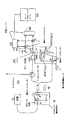
本発明の開示に従ったシステム、装置、構造、ソフトウェア構成、及びプロセス/方法の例示的な実施態様、例えば、種々のOCTシステムが、実施されうる。図1は、本発明の開示に従ったシステム、装置、構造、ソフトウェア構成、及びプロセス/方法の例示的な実施態様を実施するために用いることができる、偏光感受性干渉構成の例示的な実施態様を示している。 Exemplary implementations of systems, apparatus, structures, software configurations, and processes / methods in accordance with the present disclosure, such as various OCT systems, may be implemented. FIG. 1 illustrates an exemplary embodiment of a polarization sensitive interference configuration that can be used to implement an exemplary embodiment of a system, apparatus, structure, software configuration, and process / method according to the present disclosure. Is shown.
特に、図1の略図に示されるように、本発明の開示に従った装置及び/又はシステムの例示的な構成は、例えば、電磁放射又は光シグナルを生じるために構成されうる、素早い波長調整源10を含むことができる。このような放射及び/又は光シグナルは、定常偏光コントローラーを通じて送信され、次いで、偏光解消ユニット/構造50へと入ることができる。このような偏光解消ユニット/構造は、水平面に対して例えば45度に方向づけられた、任意のポラライザ−20を含むことができる。光(例えば、又は他の電磁放射)は、次いで、第一の偏光ビームスプリッター30によって、例えば、直交した偏光状態(例えば、水平及び垂直)で同等の強度へと分割されうる。水平及び垂直偏光状態は、第二の偏光ビームスプリッター40中でビームパスが再結合する前は、それぞれ、異なったパス長に沿って伝わりうる。直交する偏光状態間のパス長の違いは、好ましくは、光/放射源の瞬間コヒーレンス長より大きくできる。
In particular, as shown in the schematic diagram of FIG. 1, an exemplary configuration of an apparatus and / or system according to the present disclosure is a quick wavelength tuning source that can be configured, for example, to produce electromagnetic radiation or an optical signal. 10 can be included. Such radiation and / or light signals can be transmitted through a stationary polarization controller and then enter the depolarization unit / structure 50. Such a depolarizing unit / structure can include an optional polarizer-20 oriented at, for example, 45 degrees relative to the horizontal plane. The light (eg, or other electromagnetic radiation) can then be split by the first
第二の偏光ビームスプリッター40を出た後に、光/放射は、偏光解消されて、偏光がゼロ度となり得る。光/放射は、サンプルアーム要素及び参照アーム要素へと分離されうる。サンプルアーム光/放射要素は、サーキュレーター70及びサンプルアーム200へと向けられうる。サンプルからの反射光/放射は、サーキュレーターによって、音響光学モジュレーター(AOM)クリスタル160及び非偏光ビームスプリッター130上の入射へと向けられうる。参照アーム光/放射は、例えば、偏光ビームスプリッター80によって、偏光していない光/放射を2つの部分に分割することができる偏光標識状態ユニット/構造210へと向けられうる。2つ(又はそれ以上)の部分が、AOM Freq 1 100及びAOM Freq 2 110によって周波数シフトを受信し、そこでは、AOM Freq 1 100によって導入された周波数シフトは、AOM Freq 2 110によって導入された周波数シフトとは異なることができる。
After exiting the second
図1の例示的な実施態様に示されるように、直交する偏光(例えば、2又はそれ以上)は、偏光ビームスプリッター90によって再結合されうる。光/放射は、任意に、Quarter Wave Plate (QWP)120を通じて、及び/又は光学ファイバを介して、及び/又は自由空間を通じて、非偏光ビームスプリッター130へと伝播され、サンプル及び参照アーム光/放射を再結合し、ビームパス133、137中に干渉縞を形成できる。ビームパス133、137中の光/放射は、例えば、それぞれ、偏光ビームスプリッター140、150によって、直交する偏光状態へと分割され、そして、第一の平衡レシーバー170は、一つの偏光状態のための平衡干渉シグナルを受け取ることができ、かつ、第二の平衡レシーバー180は、直交する偏光状態のための平衡干渉シグナルを受け取ることができる。
As shown in the exemplary embodiment of FIG. 1, orthogonally polarized light (eg, two or more) can be recombined by a polarizing beam splitter 90. The light / radiation is optionally propagated through the Quarter Wave Plate (QWP) 120 and / or through the optical fiber and / or through free space to the
例えば、参照アーム光/放射は、AOM Freq 1 100を通過した光強度が、例えば、ビームパス133、137において同等の割合に分割されうるようにして、QWP 120及び/又はファイバベースの偏光コントローラーによって提供されうる。続いて、偏光ビームスプリッター140及び150の後の4つのビームの強度が、全てほぼ同等になり得る。加えて、AOM Freq 2 110を通過した光/放射強度は、例えば、ビームパス133、137へと同等の割合で分割され、そして引き続き、偏光ビームスプリッター140及び150後の4つのビームの強度は、全てほぼ同等になり得る。平衡レシーバーのシグナルは、イメージプロセッシングユニット/構造190によって処理されて、例えば、複合2x2ジョーンズ行列の複数(例えば、7つ)の独立したパラメーターを得ることができる。
For example, the reference arm light / radiation is provided by the
サンプルの可視偏光特性及び複合2x2ジョーンズ行列の(例えば、7つの)独立したパラメーターの検索は、以下のようにして記載できる。偏光解消後、光源10によって提供された光/放射は、無偏光状態(例えば、偏光度がゼロ)となり得る。 Searching the sample's visible polarization properties and the independent parameters (eg, 7) of the composite 2x2 Jones matrix can be described as follows. After depolarization, the light / radiation provided by the light source 10 can be in an unpolarized state (eg, zero degree of polarization).
例えば、AOM Freq 2 110を用いた参照アームは、ビームストップによって遮断されると仮定することができる。更に、同様に、無偏光サンプルアーム光/放射の偏光要素(それは、AOM Freq 1 100を通じて伝達される偏光要素と同等である)のみが、参照アーム光/放射と干渉する。干渉縞は、AOM frequency 1周波数に中心が置かれうる。平衡検出ユニット/構造170、180は、例えば、サンプル上への単一のサンプルアーム偏光状態入射のための、干渉縞の直交する要素を検出できる。AOM frequency 1に中心がある干渉縞の位相敏感復調は、サンプルアームから反射した複合電界要素の決定を容易にする。
For example, it can be assumed that a reference arm using
さらに、AOM Freq 1 100を用いた参照アームがビームストップにより遮断されたと仮定した場合、平衡検出ユニット/構造170、180は、サンプル上への直交するサンプルアーム偏光状態入射のための、干渉縞の直交する要素を検出でき、そこでは、干渉縞は、AOM frequency 2周波数に中心が置かれうる。加えて、ビームストップ無しに、例えば、サンプル上に同時に入射する2又はそれ以上のサンプル偏光状態のために、サンプル偏光情報が測定でき、そこでは、2つの偏光状態のための情報が、それぞれ、AOM frequency 1及びAOM frequency 2によって決定される搬送周波数に中心が置かれうる。
Further, assuming that the reference arm using
好ましくは、各偏光状態のシグナルバンド幅は、AOM frequency 1及びAOM frequency 2間の周波数差より小さくできる。結果として、サンプルアームから反射した2つの直交する偏光状態のための、直交する方向に沿った複合フィールド要素は、同時に測定することができ、例えば、複合2x2ジョーンズ行列の完全な決定を可能とする。
Preferably, the signal bandwidth of each polarization state can be smaller than the frequency difference between
図1の例示的な装置/システムの略図を再び参照する。光源10は、例えば、多角形スキャナーベースの波長掃引源でありうる。一つの例示的な実施態様に従って、光源10は、例えば、31K軸スキャン/秒、45mW出力、中心が1295nmである1300nmバンド幅、そして片側では空中で1.6nmの深度範囲に対して0.23nmのスペクトル線幅にて動作することができる。更なる例示的な実施態様に従って、光源10からの光/放射は、最初に、偏光解消構造(例えば、要素/構造)50へと進められ、そこでは、光は、偏光状態に依存して同等に分割され、そして片側において例えば、光源10のコヒーレンス長よりもはるかに長くできる、十分なパス長遅延で再結合されうる。 Reference is again made to the schematic diagram of the exemplary apparatus / system of FIG. The light source 10 can be, for example, a polygonal scanner based wavelength sweep source. According to one exemplary embodiment, the light source 10 has, for example, a 31K axis scan / second, 45 mW output, a 1300 nm bandwidth centered at 1295 nm, and a spectrum of 0.23 nm for a depth range of 1.6 nm in the air on one side. Can operate with line width. In accordance with a further exemplary embodiment, light / radiation from the light source 10 is first directed to a depolarization structure (eg, element / structure) 50, where the light is equivalent depending on the polarization state. And can be recombined with a sufficient path length delay on one side, for example, which can be much longer than the coherence length of the light source 10.
さらに、再結合光/放射は、偏光解消されうる。偏光解消構造50の後、例えば、光/放射の90%が、サンプルを調査するためにサンプルアーム200へと転送されることができ、そして光/放射の残りの10%が、送信参照アームへと転送されうる。送信参照アームでは、個々の偏光状態は、偏光状態標識ユニット/構造210によって標識され、そこでは、偏光状態は、例えば、2つ又はそれ以上の音響光学モジュレーター(AOM)100、110によって、例えばそれぞれ約20MHz及び40MHzへと周波数がシフトされて、周波数バンドの両側を利用できるように、及び、例えば、空中で約3.2mmになり得るようにイメージ深度範囲を倍にできる。参照送信アームからの光/放射は、干渉のために、サンプルから反射した光/放射と再結合でき、そして、例示的な偏光ダイバーシティ平衡構造中の平衡レシーバー170,180にて干渉シグナルが検出されうる。例示的な偏光ダイバーシティ構造からの複数(例えば、2つ)のチャンネルシグナルが、例えば、約100MHzサンプリング周波数にて運転されるADCボードにて同時に取得され、イメージプロセッシングユニット/構造190へと取り込まれる。例示的な可能な約50MHzのシグナルバンド幅から、個々の入射偏光状態の干渉シグナルが、例えば2つの分離した検出バンド、例えば一つは約10MHz〜30MHzのバンドで、もう一つは約30MHz〜50MHzのバンド、を占有できる。
Furthermore, the recombination light / radiation can be depolarized. After the depolarization structure 50, for example, 90% of the light / radiation can be transferred to the
特定の例示的な実施態様に従って、得られた例示的なスペクトルは、例えば、FWHMにて130nmのバンド幅で、約3072ピクセルを含むことができる。スペクトルは、周波数領域へとフーリエ変換され、そして2つの周波数バンドへと分割されうる。各周波数バンドは、復調され、そして、時間領域へとフーリエ逆変換された。次いで、時間対k−空間マッピングが、事前修正波長データ及び補完手順に基づいてスペクトルへと適用され、そして、分散補償が、参照及びサンプルアーム間の分散差によって、事前分散測定に基づいて提供されうる。更に、同等のK−空間におけるスペクトルは、深度空間において反射率プロファイルへとフーリエ変換されうる。イメージングは、先端の光学窓を用いて、携帯型調査で行われた。横断面イメージの深度範囲は、約1.4という組織の屈折率を考慮した場合、例えば、約2.3mmでありうる。例示的な強度イメージは、例えば、チャンネル及びバンドの両方の強度を合計することにより得ることができ、そして、偏光感受性(PS)の例示的なイメージは、表面状態に対しての累積位相遅延として得ることができ、0度位相遅延の黒及び180度位相遅延の白として表示され、次いで、360度で黒に戻って終わりうる。 In accordance with certain exemplary embodiments, the resulting exemplary spectrum can include approximately 3072 pixels, for example, with a bandwidth of 130 nm at FWHM. The spectrum can be Fourier transformed into the frequency domain and divided into two frequency bands. Each frequency band was demodulated and Fourier transformed back into the time domain. A time-to-k-space mapping is then applied to the spectrum based on the pre-corrected wavelength data and the interpolation procedure, and dispersion compensation is provided based on the pre-dispersion measurement, with the dispersion difference between the reference and sample arms. sell. Furthermore, the spectrum in the equivalent K-space can be Fourier transformed into a reflectance profile in depth space. Imaging was done in a portable survey using a tip optical window. The depth range of the cross-sectional image can be, for example, about 2.3 mm when considering a tissue refractive index of about 1.4. An exemplary intensity image can be obtained, for example, by summing both channel and band intensities, and an exemplary image of polarization sensitivity (PS) can be obtained as a cumulative phase delay relative to the surface state. It can be obtained and displayed as black with 0 degree phase delay and white with 180 degree phase delay, then it can end back to black at 360 degrees.
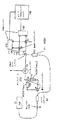
図2は、図1に示された例示的な実施態様と同じ又は同様のゴール及び/又は結果を達成できる、本発明の開示に従ったシステム/装置の他の例示的な実施態様の略図を示している。図2を参照して、偏光解消要素/構造50を除くことができ、そして、直交する独立した偏光状態の標識が、要素/構造80、90、100、110(これらの要素/構造は、上記したものと同様、同等又は同じである)を用いてサンプルアーム中にて達成できる。
FIG. 2 is a schematic diagram of another exemplary embodiment of a system / apparatus according to the present disclosure that can achieve the same or similar goals and / or results as the exemplary embodiment shown in FIG. Show. Referring to FIG. 2, the depolarization element / structure 50 can be removed, and the orthogonal independent polarization state indicators are elements /
本発明の開示の例示的な実施態様に従ったPS分析法の例示的な実施態様は、ジョーンズ行列に基づくことができる。例示的な光学システム/装置の、非偏光解消偏光特性は、複合ジョーンズ行列、Jによって表すことができ、それは、複合電界ベクトル、E=[H V]Tによって表される入射偏光状態を、送信した状態、E’=[H' V']Tへと変換する。ジョーンズ行列に基づいたPS-OCT分析法においては、表面偏光状態、[H1 V1]T、[H2 V2]Tに対してのサンプル内の偏光状態、[H1' V1']T、[H2' V2']Tの測定は、以下の式で表される。
[H1'H2';V1'V2']=exp(iΔψ1)xJoutJsJout -1[H1exp(iα)H2;V1exp(iα)V2]、
ここで、Joutは、サンプル表面から検出器への光学パスを示し、楕円リターダとして表される。Jsは、サンプルの往復ジョーンズ行列を示し、JS=JRJPの形に分解でき、ここでJR及びJPは、それぞれ、リターダ及びポラライザを示す。αは、2つの入射偏光状態での測定間の位相差である。2つの測定は、例示的な構成において同時に行い得るので、位相の不明確さは起こりそうになく、αはゼロ、α=0となる。上記式は、以下のように単純化できる。
JT=exp(−iΔψ1)x[H1'H2';V1'V2']x[H1H2;V1V2]-1、
ここで、JTは、アウトプットパス、JT=JoutJsJout -1を含む結合ジョーンズ行列である。これは、サンプルの偏光特性の全情報を含む完全なジョーンズ行列を与える。
An exemplary embodiment of a PS analysis method according to an exemplary embodiment of the present disclosure can be based on a Jones matrix. The depolarization polarization characteristics of an exemplary optical system / device can be represented by a composite Jones matrix, J, which transmitted the incident polarization state represented by the composite electric field vector, E = [HV] T State, E '= [H'V'] Convert to T. In PS-OCT analysis based on Jones matrix, surface polarization state, polarization state in sample for [H 1 V 1 ] T , [H 2 V 2 ] T , [H 1 'V 1 '] The measurement of T , [H 2 'V 2 '] T is represented by the following equation.
[H 1 'H 2 '; V 1 'V 2 '] = exp (iΔψ 1 ) × J out J s J out −1 [H 1 exp (iα) H 2 ; V 1 exp (iα) V 2 ],
Here, J out indicates the optical path from the sample surface to the detector and is expressed as an elliptical retarder. J s denotes the sample round-Jones matrix, which can be decomposed into the form J S = J R J P , where J R and J P denote the retarder and polarizer, respectively. α is the phase difference between measurements at the two incident polarization states. Since the two measurements can be made simultaneously in an exemplary configuration, phase ambiguity is unlikely to occur and α is zero and α = 0. The above equation can be simplified as follows.
J T = exp (−iΔψ 1 ) x [H 1 'H 2 '; V 1 'V 2 '] x [H 1 H 2 ; V 1 V 2 ] -1 ,
Here, J T is a combined Jones matrix including an output path, J T = J out J s J out −1 . This gives a complete Jones matrix containing all the information about the polarization properties of the sample.
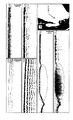
本発明の開示に従った方法、装置及びシステムの例示的な実施態様の実施を示すために、ニワトリ大腿部筋肉のサンプルを、生体外でイメージ化したもの、及びヒトの手の裏側をインビボでイメージ化したものを、図3(a)〜3(f)に示した。横断面イメージの寸法は、組織深度及び横方向は、それぞれ、2.3mm x 8mmであった。図3(a)に示されたニワトリ筋肉の例示的な強度イメージは、その深度で他の生物組織に比べた場合、緩やかな強度減衰をもつ構造を示しており、図3(b)の例示的なPSイメージは、イメージの底部に向かって、頻繁な水平の黒−白のバンドパターンを示している。図3(c)の例示的な手の強度イメージは、表層上皮及びその下の真皮構造を示しており、そして図3(d)の例示的なPSイメージは、ある程度の複屈折性を示している。図3(c)及び3(d)に示されるように、手の裏側は、他の側に比べてより強い複屈折性を示した。PSイメージは、正常組織が複屈折性である場合は、正常及び癌性組織間を区別する追加のコントラストを提供すると知られている。 In order to demonstrate the implementation of exemplary embodiments of the method, apparatus and system according to the present disclosure, a sample of chicken thigh muscle was imaged in vitro and the back of a human hand in vivo. 3 (a) to 3 (f) are shown in FIG. The dimensions of the cross-sectional image were 2.3 mm x 8 mm in tissue depth and lateral direction, respectively. The exemplary strength image of the chicken muscle shown in FIG. 3 (a) shows a structure with moderate strength decay when compared to other biological tissues at that depth, and the example of FIG. 3 (b). A typical PS image shows a frequent horizontal black-white band pattern towards the bottom of the image. The exemplary hand intensity image of FIG. 3 (c) shows the superficial epithelium and the underlying dermal structure, and the exemplary PS image of FIG. 3 (d) shows some birefringence. Yes. As shown in FIGS. 3C and 3D, the back side of the hand showed stronger birefringence than the other side. PS images are known to provide additional contrast that distinguishes between normal and cancerous tissue when normal tissue is birefringent.
動物モデルにおいて、このような例示的な手順及び実施を示すために、本発明の開示に従ったPS-OFDIシステムの例示的な実施態様を用いてマウス癌モデルをイメージ化した。癌細胞をマウスの後ろ足表面に注入し、そして例示的なPS-OFDIイメージングを1日目〜10日目まで実行した。癌は、筋肉の場所において皮膚のすぐ下に注入されているので、PS-OFDIイメージングは、正常筋肉組織と癌領域の区別を示した。横断面イメージの寸法は、組織深度及び横方向は、それぞれ、2.3mm x 12mmであった。図3(e)及び3(f)の例示的な強度及びPSイメージはともに、周辺組織から癌組織を区別しており、癌組織は、複屈折性を示さないバンドパターンなしの比較的均一な構造として現れる。癌部分は、転移なしに、正常組織部分から区別される明らかな境界をもっているように見える。
To illustrate such an exemplary procedure and implementation in an animal model, a mouse cancer model was imaged using an exemplary embodiment of the PS-OFDI system according to the present disclosure. Cancer cells were injected into the hind paw surface of mice and exemplary PS-OFDI imaging was performed from
上記は、本発明の原理を単に説明するものである。記載された実施態様に対しての、種々の変更及び置換は、本明細書に記載された教示より当業者にとって明らかである。確かに、本発明の例示的な実施態様に従った構成、システム及び方法は、イメージングシステムとともに用いることができ、そして、例えば、2005年5月26日に公開された国際公開WO2005/047813、2006年5月4日に公開された米国特許出願公開第2006/0093276号、及び2005年1月27日に公開された米国特許出願公開第2005/0018201号に記載のイメージングシステムとともに用いることができる。これらの公報の開示のすべては、ここで引用することにより本明細書の一部である。従って、本技術分野の当業者には、本明細書に明白に示され又は記載されてはいないが、本発明の原理を具現化する多数のシステム、構成及び方法を考えることができ、それらは本発明の範囲に含まれるということが理解される。加えて、本明細書中に明示的に引用されていない従来技術の知識も、ここにおいて、それらのすべての開示は本明細書に明示的に引用される。本明細書で参照された上記すべての公報及び文献の開示のすべては、引用されることにより本明細書の一部である。 The foregoing merely illustrates the principles of the invention. Various modifications and substitutions to the described embodiments will be apparent to those skilled in the art from the teachings described herein. Indeed, configurations, systems and methods according to exemplary embodiments of the present invention can be used with imaging systems and are, for example, published internationally on WO26 / 047813, 2006 published May 26, 2005. It can be used with the imaging systems described in US Patent Application Publication No. 2006/0093276 published on May 4, 2005 and US Patent Application Publication No. 2005/0018201 published on January 27, 2005. The entire disclosures of these publications are hereby incorporated by reference herein. Accordingly, those skilled in the art will recognize numerous systems, configurations and methods that may embody the principles of the present invention, although not explicitly shown or described herein. It is understood that it is within the scope of the present invention. In addition, prior art knowledge not explicitly cited herein is hereby expressly incorporated herein by reference in its entirety. All disclosures of all the above publications and documents referred to in this specification are hereby incorporated by reference.
Claims (19)
(i) 該少なくとも一つの第一の電磁放射又は(ii)少なくとも一つの更なる放射の少なくとも一つである放射の少なくとも一つの部分を、差分直交状態を有する第二及び第三の放射へと分離し、かつ、少なくとも一つの第一の特性を該第二の放射に与え及び少なくとも一つの第二の特性を少なくとも一つの第三の放射に与える(ここで、該第一の特性及び第二の特性は互いに異なっている)ように構成された少なくとも一つの第二の構成、
を含む装置。 At least one first configuration configured to provide at least one electromagnetic radiation, wherein the frequency of radiation provided by the at least one first configuration varies over time; and
converting at least one part of (i) said at least one first electromagnetic radiation or (ii) at least one of at least one further radiation into second and third radiations having differential orthogonal states Separating and imparting at least one first characteristic to the second radiation and at least one second characteristic to at least one third radiation (where the first characteristic and the second characteristic At least one second configuration, configured to be different from each other)
Including the device.
をさらに含む請求項1に記載の装置。 At least one third configuration configured to depolarize the at least one first electromagnetic radiation to produce the at least one further electromagnetic radiation, wherein the at least one second configuration. Is configured to produce the second and third radiations based on the at least one further radiation,
The apparatus of claim 1 further comprising:
をさらに含む請求項1に記載の装置。 at least some of the Jones matrix elements of the sample based on radiation received or detected from (i) at least one fourth radiation and (ii) interference between said second and third radiation At least one fourth configuration, configured to determine
The apparatus of claim 1 further comprising:
(i) 該少なくとも一つの第一の電磁放射又は(ii)少なくとも一つの更なる放射の少なくとも一つである放射の少なくとも一つの部分を、差分直交状態を有する第二及び第三の放射へと分離し、かつ、少なくとも一つの第一の特性を該第二の放射に与え及び少なくとも一つの第二の特性を少なくとも一つの第三の放射に与える(ここで、該第一及び第二の特性は互いに異なっている)こと、
を含む方法。 Providing at least one first electromagnetic radiation, wherein a radiation frequency associated with the at least one radiation varies over time; and
converting at least one part of (i) said at least one first electromagnetic radiation or (ii) at least one of at least one further radiation into second and third radiations having differential orthogonal states Separating and imparting at least one first characteristic to the second radiation and providing at least one second characteristic to at least one third radiation (wherein the first and second characteristics Are different from each other)
Including methods.
をさらに含む請求項15に記載の方法。 (i) receiving or detecting at least one fourth radiation and (ii) interference between said second and third radiation, and at least some of the Jones matrix elements of said sample based on the radiation reflected from the sample To decide,
16. The method of claim 15, further comprising:
Applications Claiming Priority (3)
| Application Number | Priority Date | Filing Date | Title |
|---|---|---|---|
| US11147908P | 2008-11-05 | 2008-11-05 | |
| US61/111,479 | 2008-11-05 | ||
| PCT/US2009/063420 WO2010054097A2 (en) | 2008-11-05 | 2009-11-05 | System and method for providing full jones matrix-based analysis to determine non-depolarizing polarization parameters using optical frequency domain imaging |
Publications (2)
| Publication Number | Publication Date |
|---|---|
| JP2012508380A true JP2012508380A (en) | 2012-04-05 |
| JP2012508380A5 JP2012508380A5 (en) | 2013-08-15 |
Family
ID=42153551
Family Applications (1)
| Application Number | Title | Priority Date | Filing Date |
|---|---|---|---|
| JP2011535668A Pending JP2012508380A (en) | 2008-11-05 | 2009-11-05 | Apparatus and method for providing a full Jones matrix based analysis for determining depolarization polarization parameters using optical frequency domain imaging |
Country Status (4)
| Country | Link |
|---|---|
| US (1) | US20120099113A1 (en) |
| EP (1) | EP2341823B1 (en) |
| JP (1) | JP2012508380A (en) |
| WO (1) | WO2010054097A2 (en) |
Cited By (3)
| Publication number | Priority date | Publication date | Assignee | Title |
|---|---|---|---|---|
| WO2014188946A1 (en) * | 2013-05-24 | 2014-11-27 | 国立大学法人筑波大学 | Jones matrix oct system and program for carrying out image processing on measured data obtained by said oct |
| JP2018025524A (en) * | 2016-08-05 | 2018-02-15 | 株式会社トーメーコーポレーション | Optical tomographic imaging device using polarization information |
| JP2018066762A (en) * | 2018-01-31 | 2018-04-26 | 国立大学法人 筑波大学 | Jones matrix oct device and program |
Families Citing this family (28)
| Publication number | Priority date | Publication date | Assignee | Title |
|---|---|---|---|---|
| US8673163B2 (en) | 2008-06-27 | 2014-03-18 | Apple Inc. | Method for fabricating thin sheets of glass |
| US7810355B2 (en) | 2008-06-30 | 2010-10-12 | Apple Inc. | Full perimeter chemical strengthening of substrates |
| CN102388003B (en) | 2009-03-02 | 2014-11-19 | 苹果公司 | Techniques for strengthening glass covers for portable electronic devices |
| US20110019354A1 (en) * | 2009-03-02 | 2011-01-27 | Christopher Prest | Techniques for Strengthening Glass Covers for Portable Electronic Devices |
| US9778685B2 (en) | 2011-05-04 | 2017-10-03 | Apple Inc. | Housing for portable electronic device with reduced border region |
| US9213451B2 (en) | 2010-06-04 | 2015-12-15 | Apple Inc. | Thin glass for touch panel sensors and methods therefor |
| US10189743B2 (en) | 2010-08-18 | 2019-01-29 | Apple Inc. | Enhanced strengthening of glass |
| US8873028B2 (en) * | 2010-08-26 | 2014-10-28 | Apple Inc. | Non-destructive stress profile determination in chemically tempered glass |
| US8824140B2 (en) | 2010-09-17 | 2014-09-02 | Apple Inc. | Glass enclosure |
| US8950215B2 (en) | 2010-10-06 | 2015-02-10 | Apple Inc. | Non-contact polishing techniques for reducing roughness on glass surfaces |
| US9725359B2 (en) | 2011-03-16 | 2017-08-08 | Apple Inc. | Electronic device having selectively strengthened glass |
| US10781135B2 (en) | 2011-03-16 | 2020-09-22 | Apple Inc. | Strengthening variable thickness glass |
| US9128666B2 (en) | 2011-05-04 | 2015-09-08 | Apple Inc. | Housing for portable electronic device with reduced border region |
| US9944554B2 (en) | 2011-09-15 | 2018-04-17 | Apple Inc. | Perforated mother sheet for partial edge chemical strengthening and method therefor |
| US9516149B2 (en) | 2011-09-29 | 2016-12-06 | Apple Inc. | Multi-layer transparent structures for electronic device housings |
| US10144669B2 (en) | 2011-11-21 | 2018-12-04 | Apple Inc. | Self-optimizing chemical strengthening bath for glass |
| US10133156B2 (en) | 2012-01-10 | 2018-11-20 | Apple Inc. | Fused opaque and clear glass for camera or display window |
| US8773848B2 (en) | 2012-01-25 | 2014-07-08 | Apple Inc. | Fused glass device housings |
| GB2499435A (en) * | 2012-02-17 | 2013-08-21 | Univ Sheffield | Production and analysis of depth-resolved electromagnetic signals |
| JP6061555B2 (en) * | 2012-08-27 | 2017-01-18 | キヤノン株式会社 | Image processing apparatus and image processing method |
| US9946302B2 (en) | 2012-09-19 | 2018-04-17 | Apple Inc. | Exposed glass article with inner recessed area for portable electronic device housing |
| US9459661B2 (en) | 2013-06-19 | 2016-10-04 | Apple Inc. | Camouflaged openings in electronic device housings |
| US9886062B2 (en) | 2014-02-28 | 2018-02-06 | Apple Inc. | Exposed glass article with enhanced stiffness for portable electronic device housing |
| JP2016086867A (en) * | 2014-10-30 | 2016-05-23 | 株式会社トーメーコーポレーション | Optical tomography imaging apparatus |
| US10852121B2 (en) * | 2016-02-12 | 2020-12-01 | The General Hospital Corporation | Apparatus and methods for high-speed and long depth range imaging using optical coherence tomography |
| JP6720051B2 (en) * | 2016-10-27 | 2020-07-08 | 株式会社日立エルジーデータストレージ | Optical image measuring device and optical image measuring method |
| CN109171659A (en) * | 2018-09-28 | 2019-01-11 | 南京航空航天大学 | Optical-fiber type sweep polarization sensitivity OCT image method and system based on Jones matrix |
| WO2022271277A1 (en) * | 2021-06-21 | 2022-12-29 | Arizona Board Of Regents On Behalf Of The University Of Arizona | Acquision of polarimetric characteristics with improved computational efficiency |
Citations (3)
| Publication number | Priority date | Publication date | Assignee | Title |
|---|---|---|---|---|
| JP2007252475A (en) * | 2006-03-22 | 2007-10-04 | Fujifilm Corp | Optical tomographic imaging system, and image-quality adjusting method for optical tomographic image |
| WO2007118129A1 (en) * | 2006-04-05 | 2007-10-18 | The General Hospital Corporation | Methods, arrangements and systems for polarization-sensitive optical frequency domain imaging of a sample |
| JP2008519264A (en) * | 2004-10-29 | 2008-06-05 | ザ ジェネラル ホスピタル コーポレイション | System and method for performing Jones matrix based analysis to measure unpolarized polarization parameters using polarization sensitive optical coherence tomography |
Family Cites Families (6)
| Publication number | Priority date | Publication date | Assignee | Title |
|---|---|---|---|---|
| US5619325A (en) * | 1995-04-04 | 1997-04-08 | Advantest Corporation | Optical system for ellipsometry utilizing a circularly polarized probe beam |
| US6208415B1 (en) | 1997-06-12 | 2001-03-27 | The Regents Of The University Of California | Birefringence imaging in biological tissue using polarization sensitive optical coherent tomography |
| ATE541202T1 (en) | 2002-01-24 | 2012-01-15 | Gen Hospital Corp | DEVICE AND METHOD FOR LOCATION AND REDUCTION OF NOISE OF SIGNALS IN LOW COHERENCE INTERFEROMETRY (LCI) AND OPTICAL COHERENCE TOMOGRAPHY (OCT) USING PARALLEL DETECTION OF SPECTRAL BANDS |
| KR20080013919A (en) * | 2005-04-22 | 2008-02-13 | 더 제너럴 하스피탈 코포레이션 | Arrangements, systems and methods capable of providing spectral-domain polarization-sensitive optical coherence tomography |
| US7292347B2 (en) * | 2005-08-01 | 2007-11-06 | Mitutoyo Corporation | Dual laser high precision interferometer |
| WO2007044612A2 (en) * | 2005-10-07 | 2007-04-19 | Bioptigen, Inc. | Imaging systems using unpolarized light and related methods and controllers |
-
2009
- 2009-11-05 US US13/127,883 patent/US20120099113A1/en not_active Abandoned
- 2009-11-05 WO PCT/US2009/063420 patent/WO2010054097A2/en active Application Filing
- 2009-11-05 EP EP09825421.2A patent/EP2341823B1/en active Active
- 2009-11-05 JP JP2011535668A patent/JP2012508380A/en active Pending
Patent Citations (3)
| Publication number | Priority date | Publication date | Assignee | Title |
|---|---|---|---|---|
| JP2008519264A (en) * | 2004-10-29 | 2008-06-05 | ザ ジェネラル ホスピタル コーポレイション | System and method for performing Jones matrix based analysis to measure unpolarized polarization parameters using polarization sensitive optical coherence tomography |
| JP2007252475A (en) * | 2006-03-22 | 2007-10-04 | Fujifilm Corp | Optical tomographic imaging system, and image-quality adjusting method for optical tomographic image |
| WO2007118129A1 (en) * | 2006-04-05 | 2007-10-18 | The General Hospital Corporation | Methods, arrangements and systems for polarization-sensitive optical frequency domain imaging of a sample |
Cited By (5)
| Publication number | Priority date | Publication date | Assignee | Title |
|---|---|---|---|---|
| WO2014188946A1 (en) * | 2013-05-24 | 2014-11-27 | 国立大学法人筑波大学 | Jones matrix oct system and program for carrying out image processing on measured data obtained by said oct |
| JP2014228473A (en) * | 2013-05-24 | 2014-12-08 | 国立大学法人 筑波大学 | Jones matrix oct system and program for performing image processing of measurement data obtained by the oct |
| US10470663B2 (en) | 2013-05-24 | 2019-11-12 | University Of Tsukuba | Jones matrix OCT system and program for carrying out image processing on measured data obtained by said OCT |
| JP2018025524A (en) * | 2016-08-05 | 2018-02-15 | 株式会社トーメーコーポレーション | Optical tomographic imaging device using polarization information |
| JP2018066762A (en) * | 2018-01-31 | 2018-04-26 | 国立大学法人 筑波大学 | Jones matrix oct device and program |
Also Published As
| Publication number | Publication date |
|---|---|
| EP2341823A2 (en) | 2011-07-13 |
| WO2010054097A3 (en) | 2010-07-29 |
| EP2341823A4 (en) | 2013-04-24 |
| WO2010054097A2 (en) | 2010-05-14 |
| US20120099113A1 (en) | 2012-04-26 |
| EP2341823B1 (en) | 2016-06-15 |
Similar Documents
| Publication | Publication Date | Title |
|---|---|---|
| JP2012508380A (en) | Apparatus and method for providing a full Jones matrix based analysis for determining depolarization polarization parameters using optical frequency domain imaging | |
| US7742173B2 (en) | Methods, arrangements and systems for polarization-sensitive optical frequency domain imaging of a sample | |
| JP5175101B2 (en) | System and method for performing Jones matrix based analysis to measure unpolarized polarization parameters using polarization sensitive optical coherence tomography | |
| US9448056B2 (en) | System for fourier domain optical coherence tomography | |
| EP2745092B1 (en) | Attaching optical coherence tomography systems onto smartphones | |
| US9086264B2 (en) | Polarization sensitive spectral domain OCT using an interference signal modulated at a constant frequency and a two-path reference arm with a single reference mirror | |
| US11701004B2 (en) | Multi-fiber optical probe and optical coherence tomography system | |
| US20130128264A1 (en) | Single-mode optical fiber-based angle-resolved low coherence interferometric (lci)(a/lci) and non-interferometric systems and methods | |
| US20110075153A1 (en) | Compact isolated analysis system | |
| KR101053222B1 (en) | Optical Coherence Tomography Device Using Multi-line Camera | |
| JP2010151684A (en) | Polarization sensitive optical image measuring instrument for extracting local double refraction information | |
| CN113670827A (en) | Polarization sensitive optical coherence-hyperspectral microimaging device and detection method thereof | |
| Villiger et al. | Polarization Sensitive Optical Coherence Tomography for Imaging of Wound Repair | |
| Hartl et al. | Cross-Polarized Optical Coherence Tomography System with Unpolarized Light. Photonics 2022, 9, 76 | |
| Jiao et al. | Characterization of the polarization properties of biological tissues with fiber-based Mueller-matrix optical coherence tomography | |
| Zurauskas et al. | Polarization sensitive en face optical coherence tomography using multichannel acousto-optic deflectors | |
| Gulsen et al. | Characterization of Tissue Birefringence with a High Speed Polarization Sensitive OCT System | |
| Gelikonov | Methods of cross polarization OCT | |
| Gelikonov | Features of cross-polarization imaging |
Legal Events
| Date | Code | Title | Description |
|---|---|---|---|
| A621 | Written request for application examination |
Free format text: JAPANESE INTERMEDIATE CODE: A621 Effective date: 20121102 |
|
| A521 | Written amendment |
Free format text: JAPANESE INTERMEDIATE CODE: A523 Effective date: 20130628 |
|
| A977 | Report on retrieval |
Free format text: JAPANESE INTERMEDIATE CODE: A971007 Effective date: 20130913 |
|
| A131 | Notification of reasons for refusal |
Free format text: JAPANESE INTERMEDIATE CODE: A131 Effective date: 20131001 |
|
| A601 | Written request for extension of time |
Free format text: JAPANESE INTERMEDIATE CODE: A601 Effective date: 20131224 |
|
| A602 | Written permission of extension of time |
Free format text: JAPANESE INTERMEDIATE CODE: A602 Effective date: 20140107 |
|
| A601 | Written request for extension of time |
Free format text: JAPANESE INTERMEDIATE CODE: A601 Effective date: 20140131 |
|
| A602 | Written permission of extension of time |
Free format text: JAPANESE INTERMEDIATE CODE: A602 Effective date: 20140207 |
|
| A601 | Written request for extension of time |
Free format text: JAPANESE INTERMEDIATE CODE: A601 Effective date: 20140225 |
|
| A602 | Written permission of extension of time |
Free format text: JAPANESE INTERMEDIATE CODE: A602 Effective date: 20140304 |
|
| A521 | Written amendment |
Free format text: JAPANESE INTERMEDIATE CODE: A523 Effective date: 20140328 |
|
| A02 | Decision of refusal |
Free format text: JAPANESE INTERMEDIATE CODE: A02 Effective date: 20140902 |
|
| RD03 | Notification of appointment of power of attorney |
Free format text: JAPANESE INTERMEDIATE CODE: A7423 Effective date: 20140911 |
|
| RD04 | Notification of resignation of power of attorney |
Free format text: JAPANESE INTERMEDIATE CODE: A7424 Effective date: 20141023 |
|
| A521 | Written amendment |
Free format text: JAPANESE INTERMEDIATE CODE: A523 Effective date: 20150105 |
|
| A911 | Transfer to examiner for re-examination before appeal (zenchi) |
Free format text: JAPANESE INTERMEDIATE CODE: A911 Effective date: 20150114 |
|
| A912 | Re-examination (zenchi) completed and case transferred to appeal board |
Free format text: JAPANESE INTERMEDIATE CODE: A912 Effective date: 20150306 |