JP2012505065A - Mammography apparatus and method for screening for the presence of malignant cells - Google Patents
Mammography apparatus and method for screening for the presence of malignant cells Download PDFInfo
- Publication number
- JP2012505065A JP2012505065A JP2011532033A JP2011532033A JP2012505065A JP 2012505065 A JP2012505065 A JP 2012505065A JP 2011532033 A JP2011532033 A JP 2011532033A JP 2011532033 A JP2011532033 A JP 2011532033A JP 2012505065 A JP2012505065 A JP 2012505065A
- Authority
- JP
- Japan
- Prior art keywords
- breast
- laser light
- detector
- malignant cells
- occurrence
- Prior art date
- Legal status (The legal status is an assumption and is not a legal conclusion. Google has not performed a legal analysis and makes no representation as to the accuracy of the status listed.)
- Pending
Links
Images


Classifications
-
- A—HUMAN NECESSITIES
- A61—MEDICAL OR VETERINARY SCIENCE; HYGIENE
- A61B—DIAGNOSIS; SURGERY; IDENTIFICATION
- A61B6/00—Apparatus for radiation diagnosis, e.g. combined with radiation therapy equipment
- A61B6/04—Positioning of patients; Tiltable beds or the like
- A61B6/0407—Supports, e.g. tables or beds, for the body or parts of the body
- A61B6/0414—Supports, e.g. tables or beds, for the body or parts of the body with compression means
-
- A—HUMAN NECESSITIES
- A61—MEDICAL OR VETERINARY SCIENCE; HYGIENE
- A61B—DIAGNOSIS; SURGERY; IDENTIFICATION
- A61B5/00—Measuring for diagnostic purposes; Identification of persons
- A61B5/0093—Detecting, measuring or recording by applying one single type of energy and measuring its conversion into another type of energy
- A61B5/0095—Detecting, measuring or recording by applying one single type of energy and measuring its conversion into another type of energy by applying light and detecting acoustic waves, i.e. photoacoustic measurements
-
- A—HUMAN NECESSITIES
- A61—MEDICAL OR VETERINARY SCIENCE; HYGIENE
- A61B—DIAGNOSIS; SURGERY; IDENTIFICATION
- A61B5/00—Measuring for diagnostic purposes; Identification of persons
- A61B5/43—Detecting, measuring or recording for evaluating the reproductive systems
- A61B5/4306—Detecting, measuring or recording for evaluating the reproductive systems for evaluating the female reproductive systems, e.g. gynaecological evaluations
- A61B5/4312—Breast evaluation or disorder diagnosis
-
- A—HUMAN NECESSITIES
- A61—MEDICAL OR VETERINARY SCIENCE; HYGIENE
- A61B—DIAGNOSIS; SURGERY; IDENTIFICATION
- A61B6/00—Apparatus for radiation diagnosis, e.g. combined with radiation therapy equipment
- A61B6/44—Constructional features of apparatus for radiation diagnosis
- A61B6/4417—Constructional features of apparatus for radiation diagnosis related to combined acquisition of different diagnostic modalities
-
- A—HUMAN NECESSITIES
- A61—MEDICAL OR VETERINARY SCIENCE; HYGIENE
- A61B—DIAGNOSIS; SURGERY; IDENTIFICATION
- A61B6/00—Apparatus for radiation diagnosis, e.g. combined with radiation therapy equipment
- A61B6/44—Constructional features of apparatus for radiation diagnosis
- A61B6/4429—Constructional features of apparatus for radiation diagnosis related to the mounting of source units and detector units
- A61B6/4435—Constructional features of apparatus for radiation diagnosis related to the mounting of source units and detector units the source unit and the detector unit being coupled by a rigid structure
- A61B6/4441—Constructional features of apparatus for radiation diagnosis related to the mounting of source units and detector units the source unit and the detector unit being coupled by a rigid structure the rigid structure being a C-arm or U-arm
-
- A—HUMAN NECESSITIES
- A61—MEDICAL OR VETERINARY SCIENCE; HYGIENE
- A61B—DIAGNOSIS; SURGERY; IDENTIFICATION
- A61B6/00—Apparatus for radiation diagnosis, e.g. combined with radiation therapy equipment
- A61B6/50—Clinical applications
- A61B6/502—Clinical applications involving diagnosis of breast, i.e. mammography
-
- A—HUMAN NECESSITIES
- A61—MEDICAL OR VETERINARY SCIENCE; HYGIENE
- A61B—DIAGNOSIS; SURGERY; IDENTIFICATION
- A61B8/00—Diagnosis using ultrasonic, sonic or infrasonic waves
- A61B8/08—Detecting organic movements or changes, e.g. tumours, cysts, swellings
- A61B8/0825—Detecting organic movements or changes, e.g. tumours, cysts, swellings for diagnosis of the breast, e.g. mammography
Abstract
本発明は、乳房内の悪性細胞を検知するためのマンモグラフィ装置に関する。このマンモグラフィ装置は、X線源、X線検知器、及び、前記X線検知器に対して前記乳房を押圧するためのパドルを備え、使用中に前記乳房に向けられるパルス状レーザー光の非集束レーザービーム源をさらに備え、前記悪性細胞の発生又は非発生をスクリーニングするように、前記乳房から発生した超音波の非接触検知のための少なくとも1つの非接触超音波検知器を備えることを特徴とする。
【選択図】図1The present invention relates to a mammography apparatus for detecting malignant cells in a breast. The mammography apparatus includes an X-ray source, an X-ray detector, and a paddle for pressing the breast against the X-ray detector, and unfocused pulsed laser light directed to the breast during use. A laser beam source, further comprising at least one non-contact ultrasonic detector for non-contact detection of ultrasonic waves generated from the breast so as to screen for the occurrence or non-occurrence of the malignant cells; To do.
[Selection] Figure 1
Description
本発明は、乳房の悪性細胞を検知するためのマンモグラフィ装置に関し、当該装置は、X線源、X線検出器、及び、X線検出器に対して乳房を押圧するためのパドル(へら)を備える。 The present invention relates to a mammography apparatus for detecting malignant cells of a breast, and the apparatus includes an X-ray source, an X-ray detector, and a paddle for pressing the breast against the X-ray detector. Prepare.
このようなマンモグラフィ装置は、乳房の悪性細胞を早期にスクリーニングするための方法において、一般的に知られている。 Such a mammography apparatus is generally known in a method for early screening for malignant cells of the breast.
今まで、ウィキペディアのテーマ「マンモグラフィ」によれば、多くの国では、早期乳癌を診断するために、スクリーニング法として、習慣的な成人女性のマンモグラフィが奨励されており、また、現時点では、乳房検診とマンモグラフィの2つだけが、早期乳癌のスクリーニングに選択すべき方法であると記述されている。超音波乳管造影法(ductography)及び磁気共鳴映像法がマンモグラフィを補助し、これによって、超音波がマンモグラフィにおいて見つかった腫瘤又はマンモグラムにおいて見えない触知腫瘤のさらなる評価に典型的に使用される。このようなマンモグラフィは、(調査を受けた集団によっては)少なくとも約20%の偽陰性(癌の見落とし)率があることが報告されている。X線画像化は、悪性細胞と正常な腺組織である周囲の細胞とを比較するときに、識別力が乏しいという性質を有することが知られている。より大きい胸(より低年齢のグループにおいて顕著であるが、高年齢の女性でもまた発生する)浸潤性乳房腫瘍は、X腺画像化により描写することは難しい。これらは正常な腺組織に簡単に隠れることができる。顕微鏡レベルでの主要な相違は、浸潤性腫瘍は血管新生と呼ばれる現象を表すことである。これらの腫瘍において、新しく形成された蛇行性(入り組んだ)血管は、(急成長する)腫瘍にグルコース及び酸素を供給することが必要であるヘモグロビンを含んだ血球で見ることができる。 Until now, according to the Wikipedia theme “Mamography”, many countries have encouraged habitual adult female mammography as a screening method to diagnose early breast cancer, and at present, breast screening Only two are described as the method of choice for early breast cancer screening. Ultrasound ductography and magnetic resonance imaging assist mammography, which is typically used for further evaluation of tumors where ultrasound is found in mammography or invisible in mammograms. Such mammography has been reported to have a false negative (cancer oversight) rate of at least about 20% (depending on the population studied). X-ray imaging is known to have the property of poor discrimination when comparing malignant cells with surrounding cells that are normal glandular tissue. Larger breast (prominent in older groups but also occurs in older women) invasive breast tumors are difficult to delineate by X-ray imaging. They can be easily hidden in normal glandular tissue. The main difference at the microscopic level is that invasive tumors exhibit a phenomenon called angiogenesis. In these tumors, newly formed tortuous (complex) blood vessels can be seen in blood cells containing hemoglobin that are required to supply glucose and oxygen to the (rapidly growing) tumor.
公知のマンモグラフィ法及び装置は、乳癌の早期検知に使用されているが、これは多数の人のスクリーニングに関わる。現在、約1億人の女性が毎年スクリーニングを受けており、結果として、スクリーニングの状況において非常に短い時間が利用可能である。典型的な定常のスクリーニング時間は約5〜10分程度である。調査によれば、スクリーニングにおいて、かなり多くの数の癌が見逃されており、これは、公知のマンモグラフィテストの限られた診断価値(有用性)、及び、その結果としてのスクリーニングに使用できる限られた時間及び施設によるものである。そこで、後日の、乳癌の発生の調査の第2ステージを軽減するために、偽陰性率が実質的に減少し、且つ、悪性細胞の発生可能性のより正確な検知が可能になるように、先行技術から知られるマンモグラフィ装置及び方法を改善する必要がある。 Known mammography methods and devices are used for early detection of breast cancer, which involves the screening of large numbers of people. Currently, about 100 million women are screened every year, and as a result, a very short time is available in the screening situation. Typical stationary screening times are on the order of about 5-10 minutes. Studies have shown that a significant number of cancers have been missed in screening, which is the limited diagnostic value (usefulness) of known mammography tests and the limited use that can be used for the resulting screening. Time and facilities. Therefore, in order to reduce the second stage of the investigation of the occurrence of breast cancer at a later date, the false negative rate is substantially reduced, and a more accurate detection of the likelihood of malignant cells is possible. There is a need to improve the mammography apparatus and methods known from the prior art.
さらに、本発明の目的は、公知のマンモグラフィ装置及び方法での調査率などの現在のワークフロー(作業の流れ)を損なわずに、すなわち、現在の必要な作業の手際を複雑にすることなく、上記目的を達成するために、マンモグラフィ装置及び方法を発明することにある。 Furthermore, the object of the present invention is the above-mentioned without compromising the current workflow (work flow) such as the survey rate in the known mammography apparatus and method, that is, without complicating the current required work. In order to achieve the object, it is to invent a mammography apparatus and method.
米国特許文献US2008/0249415号は、超音波プローブをその中に装着できる開口部が設けられているパドルを有するX線画像化に基づいたマンモグラフィ診断装置を開示する。この装置は、超音波走査(スキャン)を圧縮パドルに圧縮/固定された乳房に実行し、仮想画像として、得られた超音波画像を使用することによって圧縮された乳房画像を再現する。これによって、圧縮/固定された乳房の超音波画像、及び、体積データを得る。この公知のシステムは、多くの人々に、信頼性のあるスクリーニング作業をすることには適していない。圧縮パドルの開口部を利用する必要性により、この公知の装置で得られた画像データは、再現性の欠如、及び、適用されたX線画像化の質に付随する技術的条件の観点において、信頼できない。 US Patent Publication No. US 2008/0249415 discloses a mammography diagnostic device based on X-ray imaging having a paddle with an opening into which an ultrasound probe can be mounted. This device performs an ultrasound scan on a breast compressed / fixed in a compression paddle and reproduces the compressed breast image by using the resulting ultrasound image as a virtual image. As a result, a compressed / fixed breast ultrasound image and volume data are obtained. This known system is not suitable for many people to perform reliable screening tasks. Due to the need to utilize the opening of the compression paddle, the image data obtained with this known apparatus is in view of the lack of reproducibility and technical conditions associated with the quality of the applied X-ray imaging. Untrusted.
論文“First Clinical Trials of the Twente Photoacoustic Mammoscope(PAM)”(SPIEの会報−International Society for Optical Engineering,2007,ISSN−0277−786X,Vol.6629,頁66 2917−1−12、Vaartjes S.E.他著)は、光音響の利用及び、得られる超音波画像と、前もって得られているX線マンモグラムとの比較を報告している。論文は、主に腫瘍を抱く領域において画像化が実行されるように、検査される乳房が照射区域と超音波検知器との間に適切に配置されるべきことを報告している。論文はさらに、乳房の均一な厚さ、及び、検知器との良好な音響接触を得るために乳房の圧縮が求められることを報告している。これは、患者が不快感を示すまで、圧縮機構のハンドホイールを手動で回転させることにより達成される。検査中の人は、スキャンが実行されている時間、すなわち最大45分の間、動かないままでいる。超音波ゲルが結合媒体として使用される。この論文で開示された技術は、明らかに、検知された異常部を画像化することを目的としているようであり、1回のスクリーニングに利用可能な時間が多くても5分から10分である多くの人をスクリーニングする目的には適していない。また、論文は、光音響画像化の質とX線画像化との比較を調査しているようであるが、スクリーニングへの解決策を提供していない。 Paper “First Clinical Trials of the Twenty Photoamous Mammoscope (PAM)” (SPIE Newsletter-International Society for Optical Engineering, 2007, ISSN-0266-29. Et al. Report the use of photoacoustics and a comparison of the resulting ultrasound images with previously obtained X-ray mammograms. The paper reports that the breast to be examined should be properly positioned between the irradiated area and the ultrasound detector so that imaging is performed primarily in the area bearing the tumor. The paper further reports that breast compression is required to obtain uniform breast thickness and good acoustic contact with the detector. This is accomplished by manually rotating the compression mechanism handwheel until the patient feels uncomfortable. The person under examination remains stationary for the time the scan is being performed, i.e. up to 45 minutes. Ultrasonic gel is used as the binding medium. Apparently, the technique disclosed in this paper seems to aim at imaging the detected abnormal part, and the time available for one screening is at most 5 to 10 minutes. It is not suitable for screening people. The paper also seems to investigate a comparison between photoacoustic imaging quality and X-ray imaging, but does not provide a solution to screening.
この技術における一般的な理解は、EP−A−A493380号に開示されているような光音響分光法の利用であり、そこでは、被験者の細胞が短時間の所定波長の光のパルスで照射を受け、目的の光音響信号を生成するように、ヘモグロビンの吸収スペクトル帯にある波長を有する、短時間の光パルスで励起された、人間の乳房の組織の形態の超音波画像を検知するために検知器要素への接続ゲルの利用を必要とする。 A general understanding in this technology is the use of photoacoustic spectroscopy, as disclosed in EP-A-A493380, where a subject's cells are irradiated with a short pulse of light of a predetermined wavelength. In order to detect an ultrasound image in the form of human breast tissue, excited by a short time light pulse, having a wavelength in the absorption spectrum band of hemoglobin so as to generate a desired photoacoustic signal Requires the use of a connecting gel to the detector element.
例えば、“Http://en.wikipedia.org/wiki/medical ultrasonography”が示すとおり、超音波検査は、典型的には、患者の上に直接配置され、且つ、患者の上を移動する(トランスデューサーと呼ばれる)手持ちのプローブを使用する。水性ゲルは、トランスデューサーと患者との間を超音波で結合させるように使用される。したがって、従来技術では、超音波がとにかく検知されることを可能にするように超音波はゲルの使用を必要とする。しかしながら、ゲルの使用は、乳房の悪性細胞の発生を素早く検知するためのスクリーニングプログラムを実行するために考案された装置において使用するには禁忌である。 For example, as indicated by “http://en.wikipedia.org/wiki/medicalultrasonography”, an ultrasound examination is typically placed directly on a patient and moves over the patient (trans Use a hand-held probe (called a transducer). Aqueous gels are used to ultrasonically couple between the transducer and the patient. Thus, in the prior art, ultrasound requires the use of a gel to allow the ultrasound to be detected anyway. However, the use of gels is contraindicated for use in devices designed to implement a screening program to quickly detect the development of breast malignant cells.
全ての先行技術では禁忌とされる教示にもかかわらず、添付した1以上の請求項の特徴を有するマンモグラフィ装置及び方法に本発明が具現化される。本発明のマンモグラフィ装置は、使用中に乳房に向けられる、パルス状のレーザー光を発生させる非集束レーザー光源を備え、且つ、この装置は、血管新生の発生をスクリーニングするように、前記乳房から発生する超音波の非接触検知のための少なくとも1つの非接触超音波検知器を備えることを特徴とする。 Despite the teachings that are contraindicated in all prior art, the present invention is embodied in a mammography apparatus and method having the features of one or more of the appended claims. The mammography device of the present invention comprises an unfocused laser light source that generates a pulsed laser beam that is directed to the breast during use, and the device generates from the breast to screen for the occurrence of angiogenesis It comprises at least one non-contact ultrasonic detector for non-contact detection of ultrasonic waves.
本発明の装置は、適当な画質で光音響信号の画像化をすることを意図しておらず、また適してもおらず、スクリーニングが陽性の結果を提供した場合、さらなる検査を実施するために、悪性細胞の発生を単にスクリーニングすることだけを意図している。 The device of the present invention is not intended or suitable for imaging a photoacoustic signal with a suitable image quality, and in order to carry out further tests if the screening provided a positive result. It is intended only to screen for the development of malignant cells.
本発明によるマンモグラフィ装置で、X線マンモグラフィ検知法と、非集束パルスレーザー光が乳房に向けられ、乳房内の誘起超音波が検知器で測定され、検知器と乳房との間に接触ゲルを塗布することがない近赤外線非接触光音響検知法と、を同時に且つ組み合わせて使用することによって、乳房の悪性細胞の発生を迅速に検知するように、スクリーニングプログラムを実行するための方法を利用することが可能である。予想に反して、この方法及び装置は、乳房における悪性細胞の発生及びその供給血管をスクリーニングすることに効果的であることが証明されている。 In the mammography apparatus according to the present invention, an X-ray mammography detection method, unfocused pulsed laser light is directed to the breast, induced ultrasound in the breast is measured by the detector, and a contact gel is applied between the detector and the breast. Utilizing a method for executing a screening program to rapidly detect the development of malignant cells in the breast by using simultaneously and in combination with a near-infrared non-contact photoacoustic detection method that does not have to do Is possible. Contrary to expectation, this method and apparatus has proven effective in screening for the development of malignant cells in the breast and its supplying blood vessels.
レーザー光源がX線源の隣又は近傍に配置され、レーザー光源が乳房の方向にパドルを通してレーザー光を指向することが可能である。あるいは、オプティクスのアウトレット(出力口)が乳房に対してレーザー光を向けるように、レーザー光を伝送するために、パドルにグラスファイバーオプティクスを設ける。 A laser light source can be placed next to or near the x-ray source, and the laser light source can direct the laser light through the paddle in the direction of the breast. Alternatively, a glass fiber optics is provided in the paddle to transmit the laser light so that the outlet of the optics directs the laser light toward the breast.
発明の一態様では、超音波検知器がレーザー誘起超音波(レーザーで誘起された超音波)を検知するときにレーザー光の方向をモニタリングするように、レーザー光は方向転換可能であり、その方向が測定可能である。レーザー光のデフォーカスを変更することにより、乳房の特定のセグメントを誘起することができる。このようにすることで、乳房内で誘起された超音波が検知されたときに、デフォーカスされたパルス状レーザー光の方向が測定され、そして、悪性細胞及びそれらの供給血管が位置する方向の粗い測定として、前記測定されたレーザー光の方向を使用することができる。レーザー光の方向は音響波が生成された瞬間に分かるので、その方向はマンモグラムの空間的な情報に合致しうる。すなわち、マンモグラフィ自身が異常を明らかにしないときでさえ、音響信号の単なる存在が、さらなるマンモグラフィ検知の実行のためだけでなく、さらなる超音波精密検査の実行のための指標となる。 In one aspect of the invention, the laser light is divertable and the direction of the laser light is monitored so that the ultrasonic detector monitors the direction of the laser light when detecting laser-induced ultrasonic waves (laser-induced ultrasonic waves). Can be measured. By changing the defocus of the laser light, a specific segment of the breast can be induced. In this way, when the ultrasound induced in the breast is detected, the direction of the defocused pulsed laser light is measured, and in the direction in which the malignant cells and their supply vessels are located As a rough measurement, the direction of the measured laser beam can be used. Since the direction of the laser beam is known at the moment when the acoustic wave is generated, the direction can match the spatial information of the mammogram. That is, even when the mammography itself does not reveal anomalies, the mere presence of the acoustic signal is an indicator for performing further ultrasonic workups as well as performing further mammography detection.
本発明のさらなる形態では、複数の非接触超音波検知器を使用することによって、音響信号を生成する異常部の粗い位置特定をすることが可能である。この目的のために、各々の非接触超音波検知器における前記音響信号の(各々の)到達時間のずれを利用する。各々の非接触超音波検知器における到達時間は、各々の検知器に向かう行程で乳房細胞及び空気を通る前記超音波信号が移動する各々の距離によって決定される。同時に行われるX線画像化のおかげで、この粗い位置特定は、この画像に簡単に関連付けることができる。 In a further embodiment of the present invention, it is possible to roughly locate an abnormal part that generates an acoustic signal by using a plurality of non-contact ultrasonic detectors. For this purpose, the deviation of the arrival times of the acoustic signals in each non-contact ultrasonic detector is used. The arrival time at each non-contact ultrasonic detector is determined by the respective distance traveled by the ultrasonic signal through the breast cells and air on the journey toward each detector. Thanks to simultaneous X-ray imaging, this coarse localization can be easily associated with this image.
発明者は、論文“Initial results of in vivo non−invasive cancer imaging in the human breast using near−infrared photoacoustics”(Srirang Manohar他著、2007年9月17日発行の“Optics Express”誌ボリューム15の頁12277−12285)で、検査される乳房の2次元又は3次元画像を得るように、近赤外線光学画像化を使用することが示唆されていることを指摘する。しかしながら、この(接触ゲルの利用を必要とする)論文において開示された複雑な画像化装置から逸脱することの示唆及び暗示は存在しておらず、ヘモグロビン濃度及び酸素飽和度のような特定の生理学的な特徴の発生に対応する、可能性のある悪性細胞発生のための一般の指標として、パルス状レーザービーム励起から知られる光音響効果を使用していることだけを示唆及び暗示している。この効果により、本発明の装置及び方法は特徴的に細小血管網を表す浸潤性乳房腫瘍の悪性細胞をスクリーニングすることに取り組むスクリーニングをする放射線科医にとって、判断ツールとして非常に適している。 The inventor is the author of the paper “Initial results of in vivo non-investive cancer imaging in the human breast using near-infrared photoaustics, p. 77, published by Srirang Manp. Point out that it is suggested to use near-infrared optical imaging to obtain a two-dimensional or three-dimensional image of the breast to be examined. However, there is no suggestion or suggestion to deviate from the complex imaging device disclosed in this article (which requires the use of contact gels) and specific physiology such as hemoglobin concentration and oxygen saturation It suggests and implies only the use of the photoacoustic effect known from pulsed laser beam excitation as a general indicator for the development of potential malignant cells corresponding to the occurrence of typical features. This effect makes the apparatus and method of the present invention very suitable as a judgment tool for screening radiologists who are committed to screening malignant cells of invasive breast tumors that characteristically represent small vascular networks.
本発明に従い図面で図示されるマンモグラフィ装置の好適な実施形態を利用して、本発明を以下に説明する。 The invention will be described below by means of a preferred embodiment of a mammography device illustrated in the drawing according to the invention.
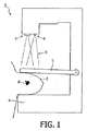
最初に図1において、乳房2内の悪性細胞8をスクリーニングするための本発明のマンモグラフィ装置1が表される。
Initially shown in FIG. 1 is a mammography apparatus 1 of the present invention for screening
マンモグラフィ装置1は、X線源3、X線検知器4、及び、前記X線検知器4に対して乳房2を押圧するためのパドル5を備える。
The mammography apparatus 1 includes an X-ray source 3, an X-ray detector 4, and a
本発明によれば、マンモグラフィ装置1は、乳房2に対して使用中にモニタリングされる所定の方向に向けられるパルス状デフォーカスレーザー光9を発生させるためのレーザー光源6をさらに備える。
According to the present invention, the mammography apparatus 1 further comprises a laser light source 6 for generating a pulsed defocused laser light 9 directed to a
本発明の装置1の第1、第2及び第3実施形態を示す図2、3及び4において示すように、装置1にはまた、前記デフォーカスレーザー光9に起因する励起によって引き起こされる、前記乳房2から発生した超音波の検知のための、少なくとも1つ及び最も一般的には数個の非接触超音波検知器7が設けられている。すなわち、密集した細小血管網によって特徴づけられる、図2、3及び4の拡大視Aによって示される悪性細胞8の発生をおおまかにスクリーニングすることが可能である。検知器7が非接触検知器であり、且つ、これらの作業には検知器7と乳房2との間に接触ゲルを塗布することが必要ないことに注目すべきである。
As shown in FIGS. 2, 3 and 4 showing the first, second and third embodiments of the device 1 of the present invention, the device 1 is also caused by excitation due to the defocused laser light 9, At least one and most commonly several non-contact ultrasonic detectors 7 are provided for the detection of ultrasonic waves generated from the
悪性浸潤腫瘍のような新生組織形成に典型的なものであるヘモグロビンを含む細小血管網において、パルス状レーザー光により音響効果が発生するが、マンモグラフィにおいてもまた発見可能な偽悪性病巣によって生じることはない。この特徴は、多くの不安、及び、侵襲性穿刺及び診断手術のような診断に関する精密検査を生じさせるような、さらなる評価のために、スクリーニングされた女性の多くの不必要な再検査のための検査機関への紹介を回避することを避けることを可能にする。 In a small blood vessel network containing hemoglobin, which is typical for neoplasia such as malignant invasive tumor, an acoustic effect is generated by pulsed laser light, but it can be caused by a pseudo-malignant lesion that can also be detected in mammography. Absent. This feature allows for many unnecessary re-examinations of screened women for further evaluation, resulting in a lot of anxiety and diagnostic workups such as invasive puncture and diagnostic surgery. Make it possible to avoid avoiding referrals to inspection agencies.
悪性細胞8の位置の検知をさせるために、(1又は複数の)超音波検知器7がレーザー誘起超音波を検知するときに、レーザー光9の方向をモニタリングするように、レーザー光9は方向転換可能であると共にその方向を測定可能とすることができる。したがって、悪性細胞8及びそれらの供給血管が位置する方向の粗い測定が提供される。
In order to detect the position of the
本発明のさらなる態様では、複数の非接触超音波検知器を使用することにより、音響信号を生成する異常部の粗い位置特定を実行可能である。この目的において、各々の非接触超音波検知器における前記音響信号の各々の到達時間を利用する。各々の非接触超音波検知器における到達時間は、各々の検知器までの行程中の乳房細胞及び空気を通って前記超音波信号が移動した各々の距離によって決定される。同時に行われるX線画像化のおかげで、この粗い位置決めをこの画像に簡単に関連づけすることが可能である。 In a further aspect of the present invention, by using a plurality of non-contact ultrasonic detectors, it is possible to perform rough localization of an abnormal part that generates an acoustic signal. For this purpose, the arrival time of each of the acoustic signals at each non-contact ultrasonic detector is used. The arrival time at each non-contact ultrasonic detector is determined by the distance that the ultrasonic signal has traveled through the breast cells and air in the process to each detector. Thanks to the simultaneous X-ray imaging, it is possible to easily associate this coarse positioning with this image.
図2に示すとおり、図1に示されたレーザー光源6から発生したレーザー光9は、パドル5を通って伝わり、乳房2内の超音波パルスを誘引することが可能である。使用されるレーザー光源6は、例えば、典型的には、30mJ/cm2のエネルギーを有し、10Hzの反復周波数の5ナノ秒のパルス幅で動作する。レーザー光源6は、1064nmの範囲で発生させる。
As shown in FIG. 2, the laser light 9 generated from the laser light source 6 shown in FIG. 1 is transmitted through the
図3は図2に示された実施形態の変形例を示しており、上方からパドル5を通って方向付けされるレーザー光とは別に、乳房2に下方から適切な位置でレーザー光源6から光パルスを伝送する、グラスファイバーオプティクス(光学器)10がX線検知器4のハウジング内に設けられている。
FIG. 3 shows a modification of the embodiment shown in FIG. 2, and separately from the laser light directed through the
図4は、図2及び3に示された実施形態のさらなる変形例を示す。この実施形態では、パドル5を通して伝送されるレーザー光が存在しない。しかし、X線検知器4のハウジング内の当該グラスファイバーオプティクス10を通る、図3に示すように下方からの光パルスに加えて、レーザー光源6から光パルスを乳房2内に上方から伝送するパドル5内に設けられたグラスファイバーオプティクス10が適切な位置に存在する。
FIG. 4 shows a further variation of the embodiment shown in FIGS. In this embodiment, there is no laser light transmitted through the
図3及び4に示された実施形態は、好適な実施形態であり、上方から乳房に導入される光パルスで超音波を誘起するだけの図2に示された実施形態と比較して、悪性細胞の発生可能性への改善された超音波応答を有する。 The embodiment shown in FIGS. 3 and 4 is a preferred embodiment and is malignant compared to the embodiment shown in FIG. 2 which only induces ultrasound with light pulses introduced into the breast from above. Has an improved ultrasonic response to cell viability.
上述した光音響効果の使用は、公知のマンモグラフィ装置で得られる、効果力が劣るスクリーニング結果を補うことに特に適している。組み合わることで、スクリーニング結果は、効果的に改善される。従来技術のスクリーニング法による検査時間を延ばすこと又は複雑にする必要を生じることなく、公知のマンモグラフィ装置及び方法と比較して、著しく低い偽陰性率及び低い偽陽性率の両方の結果が得られる。 The use of the above-described photoacoustic effect is particularly suitable for supplementing the screening results obtained with a known mammography apparatus with inferior effectiveness. In combination, screening results are effectively improved. Compared to known mammography devices and methods, results in both a significantly lower false negative rate and a lower false positive rate are obtained without the need to extend or complicate examination time with prior art screening methods.
Claims (7)
使用中に前記乳房(2)に向けられるパルス状レーザー光の非集束レーザービーム源(6)をさらに備え、
前記悪性細胞(8)の発生又は非発生をスクリーニングするように、前記乳房(2)から発生した超音波の非接触検知のための少なくとも1つの非接触超音波検知器(7)を備えることを特徴とするマンモグラフィ装置(1)。 In the breast (2), comprising an X-ray source (3), an X-ray detector (4), and a paddle (5) for pressing the breast (2) against the X-ray detector (4) In the mammography device (1) for detecting malignant cells (8),
Further comprising an unfocused laser beam source (6) of pulsed laser light directed to the breast (2) during use;
Comprising at least one non-contact ultrasonic detector (7) for non-contact detection of ultrasonic waves generated from the breast (2) so as to screen for the occurrence or non-occurrence of the malignant cells (8). Characteristic mammography device (1).
前記乳房(2)内の前記悪性細胞(8)及びそれらの供給血管の発生又は非発生をスクリーニングするように、非集束パルス状レーザー光(9)が前記乳房(2)に向けられ、前記乳房(2)内の誘起超音波が検知器(7)で測定され、前記検知器と前記乳房(2)との間に接触ゲルを適用しないことを特徴とする方法。 A method for screening for the occurrence of malignant cells in the breast (2) by using an X-ray mammography detection method and a near-infrared photoacoustic non-contact detection method simultaneously and in combination,
Unfocused pulsed laser light (9) is directed to the breast (2) to screen for the occurrence or non-occurrence of the malignant cells (8) and their supply vessels in the breast (2), and the breast (2) The induced ultrasound in (2) is measured with a detector (7), and no contact gel is applied between the detector and the breast (2).
Applications Claiming Priority (5)
| Application Number | Priority Date | Filing Date | Title |
|---|---|---|---|
| NL2002092A NL2002092C (en) | 2008-10-13 | 2008-10-13 | Mammography-apparatus and method for screening the occurrence of malignant cells. |
| NL2002092 | 2008-10-13 | ||
| NL2003122 | 2009-07-03 | ||
| NL2003122 | 2009-07-03 | ||
| PCT/NL2009/050601 WO2010044660A1 (en) | 2008-10-13 | 2009-10-07 | Mammography-apparatus and method for screening the occurrence of malignant cells |
Publications (1)
| Publication Number | Publication Date |
|---|---|
| JP2012505065A true JP2012505065A (en) | 2012-03-01 |
Family
ID=41338651
Family Applications (1)
| Application Number | Title | Priority Date | Filing Date |
|---|---|---|---|
| JP2011532033A Pending JP2012505065A (en) | 2008-10-13 | 2009-10-07 | Mammography apparatus and method for screening for the presence of malignant cells |
Country Status (7)
| Country | Link |
|---|---|
| US (1) | US20110245666A1 (en) |
| EP (1) | EP2341832B1 (en) |
| JP (1) | JP2012505065A (en) |
| CN (1) | CN102215752A (en) |
| BR (1) | BRPI0920218A2 (en) |
| CA (1) | CA2740350A1 (en) |
| WO (1) | WO2010044660A1 (en) |
Cited By (1)
| Publication number | Priority date | Publication date | Assignee | Title |
|---|---|---|---|---|
| WO2017007086A1 (en) * | 2015-07-09 | 2017-01-12 | 한국전기연구원 | Breast cancer diagnosis device |
Families Citing this family (17)
| Publication number | Priority date | Publication date | Assignee | Title |
|---|---|---|---|---|
| JP5634077B2 (en) * | 2010-02-02 | 2014-12-03 | キヤノン株式会社 | Acoustic wave receiver |
| JP5932243B2 (en) * | 2011-05-31 | 2016-06-08 | キヤノン株式会社 | apparatus |
| DE102012106678A1 (en) * | 2011-07-28 | 2013-01-31 | Electronics And Telecommunications Research Institute | An image diagnosis device including an X-ray image tomosynthesis device and a photoacoustic image device, and image diagnosis method using the same |
| KR20140059466A (en) * | 2012-11-08 | 2014-05-16 | 이화여자대학교 산학협력단 | Apparatus for photoacoustic scanning for diagnosis of breast cancer |
| TWM458203U (en) * | 2012-12-17 | 2013-08-01 | Ind Tech Res Inst | Photoacoustic detector, photoacoustic board and dector using the photoacoustic board |
| KR101492803B1 (en) * | 2013-09-17 | 2015-02-12 | 계명대학교 산학협력단 | Apparatus and method for breast tumor detection using tactile and near infrared hybrid imaging |
| CN104382558B (en) * | 2014-11-21 | 2016-06-15 | 南京星顿医疗科技有限公司 | A kind of double mode mammary gland three-dimensional image forming apparatus and method |
| JP6611428B2 (en) | 2014-12-09 | 2019-11-27 | キヤノン株式会社 | Mammography system |
| CN104825180A (en) * | 2015-04-23 | 2015-08-12 | 北京大学 | Tri-modal breast imaging system and imaging method thereof |
| CN105147398A (en) * | 2015-09-30 | 2015-12-16 | 深圳市人民医院 | Multi-mode imageology system for screening and monitoring breast cancer |
| CN105193447A (en) * | 2015-10-09 | 2015-12-30 | 汕头市超声仪器研究所有限公司 | X-ray and ultrasound combined breast examination device and fusion imaging method thereof |
| AU2017356139A1 (en) | 2016-11-08 | 2019-04-04 | Hologic, Inc. | Imaging with curved compression elements |
| WO2019033022A1 (en) | 2017-08-11 | 2019-02-14 | Hologic, Inc. | Breast compression paddle having an inflatable jacket |
| CN110996801B (en) | 2017-08-11 | 2023-10-03 | 豪洛捷公司 | Breast compression plate with near corners |
| EP4129188A1 (en) | 2017-08-16 | 2023-02-08 | Hologic, Inc. | Techniques for breast imaging patient motion artifact compensation |
| KR20220130759A (en) | 2020-01-24 | 2022-09-27 | 홀로직, 인크. | Horizontal-Displaceable Foam Breast Compression Paddles |
| CN111297397A (en) * | 2020-03-20 | 2020-06-19 | 临海迪萨智能技术有限公司 | Zero-contact ultrasonic detector for medical staff |
Citations (10)
| Publication number | Priority date | Publication date | Assignee | Title |
|---|---|---|---|---|
| JPH11514549A (en) * | 1996-01-31 | 1999-12-14 | ザ ボード オブ リージェント オブ ザ ユニバーシティ オブ テキサス システム | Laser optical acoustic imaging equipment |
| JP2000517414A (en) * | 1996-04-19 | 2000-12-26 | ユニヴァーシティー オヴ ミシガン | Method and apparatus for three-dimensional ultrasonic microscopy using short pulse excitation and three-dimensional ultrasonic microscope used therein |
| WO2001017424A1 (en) * | 1999-09-03 | 2001-03-15 | Ut-Battelle, Llc. | Method and apparatus of spectro-acoustically enhanced ultrasonic detection for diagnostics |
| US6694173B1 (en) * | 1999-11-12 | 2004-02-17 | Thomas Bende | Non-contact photoacoustic spectroscopy for photoablation control |
| JP2005021380A (en) * | 2003-07-02 | 2005-01-27 | Toshiba Corp | Living body information imaging apparatus |
| JP2006511298A (en) * | 2002-12-18 | 2006-04-06 | バーバラ アン カーマノス キャンサー インスティチュート | Computerized ultrasonic risk assessment system |
| US20060253025A1 (en) * | 2005-04-21 | 2006-11-09 | Kaufman Jonathan J | Ultrasonic Bone Assessment Apparatus and Method |
| WO2007088709A1 (en) * | 2006-01-31 | 2007-08-09 | Kansai Technology Licensing Organization Co., Ltd. | 3d acoustic imaging device and 3d acoustic imaging method |
| US20080181851A1 (en) * | 2006-12-18 | 2008-07-31 | Samira Guccione | Photoacoustic contrast agents for molecular imaging |
| JP2008272459A (en) * | 2007-04-05 | 2008-11-13 | Toshiba Corp | Ultrasonic diagnosis apparatus, breast imaging system, and breast imaging program |
Family Cites Families (4)
| Publication number | Priority date | Publication date | Assignee | Title |
|---|---|---|---|---|
| US5999836A (en) * | 1995-06-06 | 1999-12-07 | Nelson; Robert S. | Enhanced high resolution breast imaging device and method utilizing non-ionizing radiation of narrow spectral bandwidth |
| US7354401B1 (en) * | 2002-06-19 | 2008-04-08 | Toelken L Taizo | Ultrasound sex determination for sorting of avian hatchlings |
| US20060262903A1 (en) * | 2005-05-20 | 2006-11-23 | Diebold Roger M | Method and apparatus for photothermal modification of x-ray images |
| DE102005039658B3 (en) * | 2005-08-22 | 2007-07-19 | Siemens Ag | Laser device for a mammography device |
-
2009
- 2009-10-07 EP EP09741025.2A patent/EP2341832B1/en not_active Not-in-force
- 2009-10-07 JP JP2011532033A patent/JP2012505065A/en active Pending
- 2009-10-07 BR BRPI0920218A patent/BRPI0920218A2/en not_active IP Right Cessation
- 2009-10-07 WO PCT/NL2009/050601 patent/WO2010044660A1/en active Application Filing
- 2009-10-07 CN CN2009801455853A patent/CN102215752A/en active Pending
- 2009-10-07 CA CA2740350A patent/CA2740350A1/en not_active Abandoned
-
2011
- 2011-04-08 US US13/082,850 patent/US20110245666A1/en not_active Abandoned
Patent Citations (10)
| Publication number | Priority date | Publication date | Assignee | Title |
|---|---|---|---|---|
| JPH11514549A (en) * | 1996-01-31 | 1999-12-14 | ザ ボード オブ リージェント オブ ザ ユニバーシティ オブ テキサス システム | Laser optical acoustic imaging equipment |
| JP2000517414A (en) * | 1996-04-19 | 2000-12-26 | ユニヴァーシティー オヴ ミシガン | Method and apparatus for three-dimensional ultrasonic microscopy using short pulse excitation and three-dimensional ultrasonic microscope used therein |
| WO2001017424A1 (en) * | 1999-09-03 | 2001-03-15 | Ut-Battelle, Llc. | Method and apparatus of spectro-acoustically enhanced ultrasonic detection for diagnostics |
| US6694173B1 (en) * | 1999-11-12 | 2004-02-17 | Thomas Bende | Non-contact photoacoustic spectroscopy for photoablation control |
| JP2006511298A (en) * | 2002-12-18 | 2006-04-06 | バーバラ アン カーマノス キャンサー インスティチュート | Computerized ultrasonic risk assessment system |
| JP2005021380A (en) * | 2003-07-02 | 2005-01-27 | Toshiba Corp | Living body information imaging apparatus |
| US20060253025A1 (en) * | 2005-04-21 | 2006-11-09 | Kaufman Jonathan J | Ultrasonic Bone Assessment Apparatus and Method |
| WO2007088709A1 (en) * | 2006-01-31 | 2007-08-09 | Kansai Technology Licensing Organization Co., Ltd. | 3d acoustic imaging device and 3d acoustic imaging method |
| US20080181851A1 (en) * | 2006-12-18 | 2008-07-31 | Samira Guccione | Photoacoustic contrast agents for molecular imaging |
| JP2008272459A (en) * | 2007-04-05 | 2008-11-13 | Toshiba Corp | Ultrasonic diagnosis apparatus, breast imaging system, and breast imaging program |
Cited By (2)
| Publication number | Priority date | Publication date | Assignee | Title |
|---|---|---|---|---|
| WO2017007086A1 (en) * | 2015-07-09 | 2017-01-12 | 한국전기연구원 | Breast cancer diagnosis device |
| US10945694B2 (en) | 2015-07-09 | 2021-03-16 | Korea Electrotechnology Research Institute | Breast cancer diagnosis device |
Also Published As
| Publication number | Publication date |
|---|---|
| EP2341832B1 (en) | 2014-07-16 |
| CN102215752A (en) | 2011-10-12 |
| CA2740350A1 (en) | 2010-04-22 |
| EP2341832A1 (en) | 2011-07-13 |
| BRPI0920218A2 (en) | 2016-10-25 |
| WO2010044660A1 (en) | 2010-04-22 |
| US20110245666A1 (en) | 2011-10-06 |
Similar Documents
| Publication | Publication Date | Title |
|---|---|---|
| JP2012505065A (en) | Mammography apparatus and method for screening for the presence of malignant cells | |
| CA2244732C (en) | Laser opto-acoustic imaging system | |
| CN105451661B (en) | Photoacoustic image generating means and light source control method | |
| US9833187B2 (en) | Detection, diagnosis and monitoring of osteoporosis by a photo-acoustic method | |
| JP5743957B2 (en) | Photoacoustic image generation apparatus and method | |
| US20200268253A1 (en) | Photoacoustic computed tomography (pact) systems and methods | |
| US20070238953A1 (en) | Combined ultrasonic imaging and spectroscopic molecular analysis | |
| JP2011515188A (en) | A method for spectral analysis of ultrasound images to detect breast microcalcifications | |
| JP5911196B2 (en) | Photoacoustic imaging device | |
| JP2009207883A (en) | Biological information imaging apparatus and biological information analyzing method | |
| WO2007100937A2 (en) | System and method for spectroscopic photoacoustic tomography | |
| JP2009538418A (en) | Photoacoustic imaging method | |
| CN110361357B (en) | Single-array-element photoacoustic spectrum signal acquisition system and method for skin detection | |
| JP6000778B2 (en) | SUBJECT INFORMATION ACQUISITION DEVICE AND METHOD FOR CONTROLLING SUBJECT INFORMATION ACQUISITION DEVICE | |
| JPWO2010131697A1 (en) | Blood vessel inner wall analysis apparatus and blood vessel inner wall analysis method | |
| WO2013062067A1 (en) | Object information acquiring apparatus and control method for controlling the same | |
| CN214073268U (en) | Cell detection apparatus | |
| KR20130039198A (en) | Method of producing photoacoustic image for detecting calcification tissue and producing apparatus thereof | |
| US20190021639A1 (en) | Methemoglobin detection using photoacoustic imaging | |
| JP6066230B2 (en) | Photoacoustic image generation apparatus and operation method thereof | |
| Singh et al. | Breast imaging using an LED-based photoacoustic and ultrasound imaging system: a proof-of-concept study | |
| TW201414999A (en) | Photoacoustic imaging method for calcifications or microcalcifications | |
| Mahmoodian et al. | A framework of photo acoustic imaging for ovarian cancer detection by galvo-mirror system | |
| Kukk et al. | Integrated ultrasound and photoacoustic tomography for 3D imaging of human skin lesions | |
| Lamela et al. | Experimental study using optoacoustic spectroscopy (OAS) on spherical gold nanoparticles |
Legal Events
| Date | Code | Title | Description |
|---|---|---|---|
| A621 | Written request for application examination |
Free format text: JAPANESE INTERMEDIATE CODE: A621 Effective date: 20120117 |
|
| A131 | Notification of reasons for refusal |
Free format text: JAPANESE INTERMEDIATE CODE: A131 Effective date: 20130514 |
|
| A02 | Decision of refusal |
Free format text: JAPANESE INTERMEDIATE CODE: A02 Effective date: 20131029 |