JP2012503416A - Method and apparatus for trimming video images - Google Patents
Method and apparatus for trimming video images Download PDFInfo
- Publication number
- JP2012503416A JP2012503416A JP2011527796A JP2011527796A JP2012503416A JP 2012503416 A JP2012503416 A JP 2012503416A JP 2011527796 A JP2011527796 A JP 2011527796A JP 2011527796 A JP2011527796 A JP 2011527796A JP 2012503416 A JP2012503416 A JP 2012503416A
- Authority
- JP
- Japan
- Prior art keywords
- region
- picture
- data
- pictures
- encoding
- Prior art date
- Legal status (The legal status is an assumption and is not a legal conclusion. Google has not performed a legal analysis and makes no representation as to the accuracy of the status listed.)
- Pending
Links
Images


Classifications
-
- H—ELECTRICITY
- H04—ELECTRIC COMMUNICATION TECHNIQUE
- H04N—PICTORIAL COMMUNICATION, e.g. TELEVISION
- H04N19/00—Methods or arrangements for coding, decoding, compressing or decompressing digital video signals
- H04N19/50—Methods or arrangements for coding, decoding, compressing or decompressing digital video signals using predictive coding
- H04N19/59—Methods or arrangements for coding, decoding, compressing or decompressing digital video signals using predictive coding involving spatial sub-sampling or interpolation, e.g. alteration of picture size or resolution
-
- H—ELECTRICITY
- H04—ELECTRIC COMMUNICATION TECHNIQUE
- H04N—PICTORIAL COMMUNICATION, e.g. TELEVISION
- H04N19/00—Methods or arrangements for coding, decoding, compressing or decompressing digital video signals
- H04N19/85—Methods or arrangements for coding, decoding, compressing or decompressing digital video signals using pre-processing or post-processing specially adapted for video compression
-
- H—ELECTRICITY
- H04—ELECTRIC COMMUNICATION TECHNIQUE
- H04N—PICTORIAL COMMUNICATION, e.g. TELEVISION
- H04N19/00—Methods or arrangements for coding, decoding, compressing or decompressing digital video signals
- H04N19/50—Methods or arrangements for coding, decoding, compressing or decompressing digital video signals using predictive coding
- H04N19/587—Methods or arrangements for coding, decoding, compressing or decompressing digital video signals using predictive coding involving temporal sub-sampling or interpolation, e.g. decimation or subsequent interpolation of pictures in a video sequence
Landscapes
- Engineering & Computer Science (AREA)
- Multimedia (AREA)
- Signal Processing (AREA)
- Compression Or Coding Systems Of Tv Signals (AREA)
Abstract
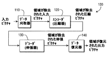
ビデオ画像の刈り取りを行う方法及び装置が提供される。装置は、符号化による圧縮の前に、符号化による圧縮に備えて、あるピクチャを前処理するデータ刈り取り手段110を含む。データ刈り取り手段は、ピクチャにおける少なくとも1つの領域を空間領域において選択的に除去する。デコーダ側で、装置は、復号化による伸張に続いて、伸張されたピクチャを受け、以前に行われた符号化処理の前に少なくとも1つの領域が除去されたことを示す情報に基づいて、伸張されたピクチャにおける少なくとも1つの領域を空間領域において選択的に復元することで、伸張されたピクチャを後処理するデータ復元手段140を含む。A method and apparatus for trimming video images is provided. The apparatus includes data pruning means 110 that preprocesses a picture in preparation for compression by encoding prior to compression by encoding. The data pruning means selectively removes at least one region in the picture in the spatial region. On the decoder side, the device receives the decompressed picture following decompression by decoding and decompresses based on information indicating that at least one region has been removed prior to the previous encoding process. A data restoration unit 140 for post-processing the decompressed picture by selectively restoring at least one area in the generated picture in the spatial domain is included.
Description
本発明は、ビデオ符号化及び復号化に関し、より詳細には、ビデオ画像の刈り取り方法及び装置に関する。
本出願は、2008年9月18日に提出された米国特許仮出願第61/098125号の利益を特許請求するものであり、この仮出願の内容は、その完全な形で本明細書に盛り込まれる。
The present invention relates to video encoding and decoding, and more particularly to a video image pruning method and apparatus.
This application claims the benefit of US Provisional Application No. 61/098125, filed Sep. 18, 2008, the contents of which are incorporated herein in their entirety. It is.
現在、高画質ビデオの要求が増え続けている。ビデオコンテンツの要求は、高い解像度、高いフレームレート、及び高いビット深度に進む傾向にある。高精細(HD)ビデオ及び他のビットレートが集中する開発に対応するビットレートの増加に対抗するため、特に、ネットワーク及び通信技術の伝送の制約に対処するため、ビットレートを更に低減する新たな技術が強く要求される。 Currently, the demand for high quality video continues to increase. Video content requirements tend to go to higher resolutions, higher frame rates, and higher bit depths. New to further reduce the bit rate to address the bit rate increase corresponding to the development of high definition (HD) video and other bit rate intensive, especially to address the transmission constraints of network and communication technology Technology is strongly required.
圧縮ビットレートを低減することに対する少なくとも2つの基本的なアプローチが存在する。第一のアプローチは、圧縮技術を改善することを含み、第二のアプローチは、圧縮前にある種の前処理を行うことを含む。 There are at least two basic approaches to reducing the compression bit rate. The first approach involves improving the compression technique and the second approach involves performing some kind of preprocessing prior to compression.
第一のアプローチ、すなわち圧縮技術を改善することに関し、この発展は、たとえばISO/IEC(International Organization for Standardization/International Electrotechnical Commission)のMPEG-1規格、ISO/IECのMPEG-2規格、ISO/IECのMPEG-4規格、及びISO/IECのMPEG-4 Part 10 AVC(Advanced Video Coding)規格/ITU-T(International Telecommunication Union, Telecommunication Sector)H.264勧告(以下“MPEG-4 AVC規格”)のような、様々なMPEG(Moving Picture Experts Group)の符号化規格の発展において容易に見る事ができる。 With regard to the first approach, i.e. improving compression technology, this development is for example the ISO-1 / IEC (International Organization for Standardization / International Electrotechnical Commission) MPEG-1 standard, ISO / IEC MPEG-2 standard, ISO / IEC MPEG-4 standard of ISO and IEC MPEG-4 Part 10 AVC (Advanced Video Coding) standard / ITU-T (International Telecommunication Union, Telecommunication Sector) H.264 recommendation (hereinafter referred to as “MPEG-4 AVC standard”) It can be easily seen in the development of various MPEG (Moving Picture Experts Group) encoding standards.
大部分の符号化規格について、量子化ステップサイズを増加することは、ビットレートを低減するために使用される手段である。しかし、この技術は、高周波の詳細の損失による深刻なブロックアーチファクト及び他の符号化アーチファクトとなる可能性がある。 For most coding standards, increasing the quantization step size is a means used to reduce the bit rate. However, this technique can lead to serious block artifacts and other coding artifacts due to loss of high frequency details.
第二のアプローチ、すなわち圧縮前のある種の前処理を行うことに関して、係る前処理の目標は、視覚の観点で重要ではない情報、又はコンテンツを著しく変更することなしに復号化処理の後に回復できる情報を除くことである。また、このビットレートの低減は、データプルーニング(刈り込み)と一般に呼ばれる。このデータプルーニングを通してビットレートの低減を行う幾つかの一般的な技術は、ロウパスフィルタ及び(フィルタリング処理として見る事ができる)ダウンサンプリング、これらに続くデコーダでのアップサンプリングの使用である。これらのスキームの1つの効果は、これらの技術はビットレートを低減するためにビデオにおける高周波情報を除くように設計されているので、復号化及び再構成されたビデオが少しぼやけて見えることである。 With respect to the second approach, i.e. performing some kind of pre-processing before compression, the goal of such pre-processing is to recover after decryption without significant changes to information or content that is not important from a visual point of view. The information that can be removed. This reduction in bit rate is generally called data pruning. Some common techniques for reducing the bit rate through this data pruning are the use of a low-pass filter and downsampling (which can be seen as a filtering process) followed by upsampling in the decoder. One effect of these schemes is that the decoded and reconstructed video looks a little blurry because these techniques are designed to remove high frequency information in the video to reduce the bit rate. .
たとえば、前に記載されたアップサンプリングのために使用される補間に関して、従来のBilinear及びBi-cubic補間を発端として、POCS(Projection Onto Convex Sets)及び非凸上の偏差分方程式のような洗練された繰り返し補間方法に続いて、広範囲の補間方法及びスキームが議論及び開発されている。 For example, with respect to the interpolation used for upsampling described earlier, the refinement such as POCS (Projection Onto Convex Sets) and non-convex deviation equation, starting with traditional Bilinear and Bi-cubic interpolation. Following the repetitive interpolation methods, a wide range of interpolation methods and schemes are discussed and developed.
エッジに沿って生じるジャーキネスを回避するため、低解像度画像のマルコフ確率場及び分散を使用したエッジ指向の補間方法が提案されている。 In order to avoid jerkiness that occurs along the edges, an edge-oriented interpolation method using Markov random fields and variances of low resolution images has been proposed.
1つの従来のアプローチは、方向性フィルタリング及びデータ融合の組み合わせを利用して、LMMSE(Linear Minimum Mean Square Error)により失われた高解像度(HR)画素を除く。別の補間アルゴリズムのグループは、ウェーブレット変換又はContourlet変換のような異なる種類の変換を使用してその対応する低解像度(LR)画像からHR画像の微細構造を予測する。 One conventional approach utilizes a combination of directional filtering and data fusion to eliminate high resolution (HR) pixels lost due to LMMSE (Linear Minimum Mean Square Error). Another group of interpolation algorithms predicts the fine structure of the HR image from its corresponding low resolution (LR) image using different types of transforms such as wavelet transforms or contourlet transforms.
先の方法のそれぞれは、水平及び垂直の両方向において、すなわち固定された規則的なデータグリッドにおいて(すなわち、全てのデータポイントは、矩形のグリッドで発見される)同じ比率でアップサンプリングするのに適している。しかし、補間がデータ刈り込みと共に使用されるとき、捨てられたデータに適合し、そしてそれぞれの画素の変動する周囲に適合して最良の性能を達成するための柔軟性が望まれる。 Each of the previous methods is suitable for upsampling in the same ratio in both horizontal and vertical directions, ie in a fixed regular data grid (ie all data points are found in a rectangular grid). ing. However, when interpolation is used with data pruning, flexibility is needed to fit the discarded data and to fit the changing perimeter of each pixel to achieve the best performance.
従来技術のこれらの課題及び問題、並びに他の課題及び問題は、ビデオ画像データの刈り取り方法及び装置に向けられる、本願発明により対処される。 These problems and problems of the prior art, as well as other problems and problems, are addressed by the present invention, which is directed to a video image data pruning method and apparatus.
本発明の態様によれば、装置が提供され、本装置は、符号化による圧縮の前に、及び符号化による圧縮に備えて、ある画像に前処理を施すデータ刈り取り手段を含む。データ刈り取り手段は、空間領域において、該画像における少なくとも1つの領域を選択的に除く。 According to an aspect of the present invention, an apparatus is provided, the apparatus including data pruning means for pre-processing an image before compression by encoding and in preparation for compression by encoding. The data pruning means selectively removes at least one region in the image in the spatial region.
本発明の別の態様によれば、方法が提供され、本方法は、符号化による圧縮の前に、及び符号化による圧縮に備えて、ある画像に前処理を施すことを含む。前処理ステップは、空間領域において、プロセッサを有するデータ刈り取り手段を使用して画像における少なくとも1つの領域を選択的に除くことを含む。 In accordance with another aspect of the present invention, a method is provided that includes pre-processing an image prior to compression by encoding and in preparation for compression by encoding. The preprocessing step includes selectively removing at least one region in the image using a data pruning means having a processor in the spatial region.
本発明の更に別の態様によれば、装置が提供され、本装置は、復号化による伸張の後に伸張された画像を受け、前に実行された符号化処理の前に少なくとも1つの領域が除去されてことを示す情報に基づいて、伸張された画像における少なくとも1つの領域を、空間領域において選択的に復元することで、伸張された画像を後処理するデータ復元手段を含む。 In accordance with yet another aspect of the present invention, an apparatus is provided for receiving a decompressed image after decompression by decoding and removing at least one region prior to a previously performed encoding process. Data restoration means for post-processing the decompressed image by selectively restoring at least one region in the decompressed image in the spatial region based on the information indicating that the decompressed image has been performed.
本発明の更なる態様によれば、方法が提供され、本方法は、復号化による伸張に続いて伸張された画像を受けることを含む。さらに、本方法は、プロセッサを有するデータ復元手段を使用して、前に実行された符号化処理の前に少なくとも1つの領域が除去されたことを示す情報に基づいて、伸張された画像における少なくとも1つの領域を選択的に復元することで、伸張された画像を後処理することを含む。 According to a further aspect of the invention, a method is provided, the method comprising receiving a decompressed image following decompression by decoding. Further, the method uses at least a region of the decompressed image based on information indicating that at least one region has been removed prior to the previously performed encoding process using data decompression means having a processor. This includes post-processing the decompressed image by selectively restoring one region.
本発明のこれらの態様、特徴及び利点、並びに他の態様、特徴及び利点は、添付図面と共に読まれることとなる例示的な実施の形態の以下の詳細な説明から明らかとなるであろう。 These aspects, features and advantages of the present invention, as well as other aspects, features and advantages will become apparent from the following detailed description of exemplary embodiments which will be read in conjunction with the accompanying drawings.
本発明は、以下の例示的な図面に従って良好に理解されるであろう。
本発明は、ビデオ画像のデータ刈り取りの方法及び装置に向けられる。
本実施の形態は、本発明を例示するものである。したがって、当業者であれば、本実施の形態に明示的に記載又は図示されないが、本発明を実施する様々なアレンジメントであって、本発明の精神及び範囲に含まれる様々なアレンジメントを創作することができることを理解されたい。
The present invention is directed to a method and apparatus for data pruning of video images.
This embodiment exemplifies the present invention. Accordingly, those skilled in the art may create various arrangements for implementing the present invention that are not explicitly described or illustrated in the present embodiment, and that fall within the spirit and scope of the present invention. Please understand that you can.
本実施の形態で引用される全ての例及び条件付き言語は、本発明及び当該技術分野を促進するために本発明者により与えられる概念の理解において読者を支援することが意図され、係る詳細に記載される例及び条件に限定されるものではないことが解釈されるべきである。 All examples and conditional languages cited in this embodiment are intended to assist the reader in understanding the concepts provided by the inventor to promote the invention and the field of art, and in such details. It should be construed that the invention is not limited to the examples and conditions described.
さらに、本発明の原理、態様及び実施の形態を示す全ての説明は、本発明の特定の例と同様に、本発明の構造的に等価な概念と機能的に等価な概念の両者を包含することが意図される。さらに、係る等価な概念は、現在知られている等価な概念と同様に、将来において開発される等価な概念、すなわち構造に関わらずに同じ機能を実行する開発されたエレメントの両者を含むことが意図される。 Further, all descriptions showing the principles, aspects and embodiments of the invention include both structurally and functionally equivalent concepts of the invention, as well as specific examples of the invention. Is intended. In addition, such equivalent concepts may include both equivalent concepts developed in the future, i.e., elements developed that perform the same function regardless of structure, as well as currently known equivalent concepts. Intended.
したがって、例えば、本実施の形態で与えられるブロック図は、本発明を実施する例示的な回路の概念図を表すことが当業者により理解されるであろう。同様に、任意のフローチャート、フローダイアグラム、状態遷移図、擬似コード等は、コンピュータ読み取り可能な記録媒体の実質的に表現され、コンピュータ又はプロセッサが明示的に示されているか否かに関わらず、係るコンピュータ又はプロセッサにより実行される様々なプロセスを表すことが理解されるであろう。 Thus, for example, it will be understood by those skilled in the art that the block diagram provided in the present embodiment represents a conceptual diagram of an exemplary circuit implementing the present invention. Similarly, any flowcharts, flow diagrams, state transition diagrams, pseudocodes, etc. may be substantially represented by computer-readable media, regardless of whether a computer or processor is explicitly indicated. It will be understood that it represents various processes performed by a computer or processor.
図示される様々なエレメントの機能は、専用ハードウェアの使用と同様に、適切なソフトウェアと関連されるソフトウェアを実行可能なハードウェアの使用により提供される場合がある。プロセッサにより提供されたとき、単一の専用プロセッサ、単一の共有プロセッサ、そのうちの幾つかが共有される複数の個々のプロセッサによる機能が提供される。さらに、用語「プロセッサ」又は「コントローラ」の明示的な使用は、ソフトウェアを実行可能なハードウェアを排他的に示すように解釈されるべきではなく、限定されれることなしに、デジタルシグナルプロセッサ(DSP)ハードウェア、ソフトウェアを記憶するリードオンリメモリ(ROM)、ランダムアクセスメモリ(RAM)及び不揮発性メモリを暗黙的に含む場合がある。 The functionality of the various elements shown may be provided through the use of hardware capable of executing software associated with the appropriate software, as well as the use of dedicated hardware. When provided by a processor, the functionality is provided by a single dedicated processor, a single shared processor, a plurality of individual processors some of which are shared. Furthermore, the explicit use of the term “processor” or “controller” should not be construed to indicate exclusively hardware capable of executing software, but without limitation, digital signal processors (DSPs). ) May implicitly include hardware, read only memory (ROM) that stores software, random access memory (RAM) and non-volatile memory.
コンベンショナル及び/又はカスタムである他のハードウェアが含まれる場合もある。同様に、図示される任意のスイッチは、単に概念的なものである。それらの機能は、プログラムロジックの動作を通して、専用ロジックを通して、プログラム制御及び専用ロジックのやり取りを通して、更には手動的に実行される場合があり、特定の技術は、文脈から更に詳細に理解されるように実装者により選択可能である。 Other hardware that is conventional and / or custom may also be included. Similarly, any switches shown are merely conceptual. These functions may be performed manually through program logic operations, through dedicated logic, through program control and dedicated logic interactions, and certain techniques will be understood in more detail from the context. Can be selected by the implementer.
本出願の特許請求の範囲では、特定の機能を実行する手段として表現される任意のエレメントは、たとえばa)その機能を実行する回路素子の組み合わせ、b)その機能を実行するソフトウェアを実行する適切な回路と組み合わされる、ファームウェア、マイクロコード等を含む任意の形式でのソフトウェア、を含むその機能を実行する任意の方法を包含することが意図される。係る特許請求の範囲により定義される本発明は、様々な引用される手段により提供される機能が結合され、請求項が求める方法で互いに纏められるという事実にある。従って、それらの機能を提供する任意の手段は、本実施の形態に示されるものと等価であると見なされる。 In the claims of this application, any element expressed as a means for performing a particular function may be, for example, a) a combination of circuit elements that perform that function, or b) appropriate software that executes that function. It is intended to encompass any method of performing that function, including firmware, software in any form, including microcode, etc., combined with such circuitry. The invention defined by such claims resides in the fact that the functions provided by the various cited means are combined and brought together in the manner desired by the claims. Accordingly, any means that provides these functions are considered equivalent to those shown in this embodiment.
本発明の「1実施の形態」又は「実施の形態」への明細書への参照は、その他の変形例と同様に、実施の形態と共に記載される特定の特徴、構造、特徴等が本発明の1実施の形態に含まれることを意味する。従って、明細書を通して様々な位置に現れる任意の他の変形例と同様に、記載「1実施の形態では」又は「実施の形態では」の出現は、必ずしも、同じ実施の形態を示すものではない。 References to the specification for “one embodiment” or “embodiment” of the present invention are based on specific features, structures, features, etc. described in the embodiment, as well as other modifications. It is meant to be included in one embodiment. Thus, as with any other variation appearing in various locations throughout the specification, the appearance of the description “in one embodiment” or “in an embodiment” does not necessarily indicate the same embodiment. .
以下の記載「/」、「及び/又は」及び「少なくとも1つの」の使用は、たとえば「A/B」、「A及び/又はB」及び「A及びBの少なくとも1つ」の場合、最初の列挙されたオプションAのみの選択、第二の列挙されたオプションBのみの選択、両方のオプション(A及びB)の選択を包含することが意図される。更なる例として、「A、B及び又はC」及び「A、B及びCの少なくとも1つ」の場合、係る記載は、最初に列挙されたオプションAのみの選択、第二の列挙されたオプションBのみの選択、第三の列挙されたオプションCのみの選択、第一及び第二の列挙されたオプション(A及びB)のみの選択、第一及び第三の列挙されたオプション(A及びC)のみの選択、又は、第二及び第三の列挙されたオプション(B及びC)のみの選択、又は、全ての3つのオプション(A及びB及びC)の選択を包含することが意図される。このことは、多数のアイテムが列挙された場合に、当業者によって容易に明らかであるように、拡張される場合がある。 The use of the following statements “/”, “and / or” and “at least one” is, for example, “A / B”, “A and / or B” and “at least one of A and B” It is intended to encompass selection of only the listed option A, selection of only the second listed option B, selection of both options (A and B). As a further example, in the case of “A, B, and / or C” and “At least one of A, B, and C”, such a statement will only select the first listed option A, the second listed option Select B only, select third enumerated option C, select only first and second enumerated options (A and B), first and third enumerated options (A and C ) Selection only, or selection of only the second and third listed options (B and C), or selection of all three options (A and B and C) . This may be extended, as will be readily apparent to those skilled in the art when a large number of items are listed.
本実施の形態で使用されたとき、用語「画像」及び「ピクチャ」は、交換可能に使用され、ビデオ系列及び/又は静止画像の一部である任意のビデオピクチャを示す場合がある。先に述べたように、本発明は、ビデオ画像のデータ刈り取り方法及び装置に向けられる。 As used in this embodiment, the terms “image” and “picture” are used interchangeably and may refer to any video picture that is part of a video sequence and / or still image. As mentioned earlier, the present invention is directed to a video image data pruning method and apparatus.
さらに、1以上の本発明の実施の形態がMPEG-4AVC規格に関して記載される一方で、本発明はこの規格のみに限定されるものではなく、本発明の精神を維持する一方で、他のビデオ符号化規格、勧告、及び、MPEG-4AVC規格の拡張を含めて、その拡張に関して利用される場合がある。 Furthermore, while one or more embodiments of the present invention are described with respect to the MPEG-4 AVC standard, the present invention is not limited to this standard alone, while maintaining the spirit of the present invention, while other video It may be used for extensions, including encoding standards, recommendations, and extensions to the MPEG-4 AVC standard.
図1を参照して、データ刈り取り及び復元の例示的なシステムは、参照符号化100により示される。本システム100は、データ刈り取り器110、エンコーダ(又は圧縮器)120、デコーダ(又は伸張器)130、及びデータ復元器140を含む。データ刈り取り器110は、符号化による圧縮の前に、あるピクチャから少なくとも1つの領域(たとえば直線、曲線、領域等)を空間領域において除く前処理を行う。次いで、エンコーダ120は、少なくとも1つの領域が除かれたピクチャを符号化する。デコーダ130は、少なくとも1つの領域が除かれた符号化されたピクチャを復号化する。データ復元器140は、空間領域において、少なくとも1つの領域を復元して復号化されたピクチャにする後処理を行う。何れかのデータ刈り取り器110、エンコーダ120、デコーダ130及びデータ復元器140は、たとえばそれら対応する機能を実行するため、1以上のプロセッサ、メモリ等を含む場合がある。たとえば、データ刈り取り器110における1以上のプロセッサは、本実施の形態で記載される前処理を行う一方で、データ復元器140における1以上のプロセッサは、本実施の形態で記載される後処理を実行する場合がある。データ刈り取り器110は、幾つかの実施の形態では、データ刈り取り器とは個別である他のエレメントを含む場合があり、他の実施の形態では、データ刈り取り器と統合される他のエレメントを含む場合がある。たとえば、実施の形態では、データ刈り取り器110(又はデータ刈り取り段階)は、間引き器及び補間器(図11参照)を含む場合がある。別の実施の形態では、データ刈り取り器110(又はデータ刈り取り段階)は、(少なくとも1つの領域の実際の除去を行うサブエレメントでとしての)データ刈り取り器、ストア又は圧縮器、及び補間器(たとえば図10参照)を含む場合がある。図1のエレメントのこれらの変形例及び他の変形例は、本発明の精神を維持しつつ、当業者により容易に創作される。
With reference to FIG. 1, an exemplary system for data pruning and restoration is indicated by
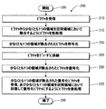
図2を参照して、データ刈り取り及び復元の例示的な方法は、参照符号200により示される。本方法200は、開始ブロック205を含み、この開始ブロックは、機能ブロック210に制御を移す。機能ブロック210は、あるピクチャを受信し、機能ブロック215に制御を移す。機能ブロック215は、該ピクチャから少なくとも1つの領域(たとえば直線、曲線、領域等)を空間領域において除くためにピクチャの前処理を行い、機能ブロック220に制御を移す。機能ブロック220は、少なくとも1つの領域が除去されたピクチャを符号化し、機能ブロック225に制御を移す。機能ブロック225は、符号化されたピクチャをデコーダ(又はデコーダを有する装置)に供給し、機能ブロック230に制御を移す。機能ブロック230は、少なくとも1つの領域が除去された符号化されたピクチャを復号化し、機能ブロック235に制御を移す。機能ブロック235は、少なくとも1つの領域が除去された復号化されたピクチャを受け、少なくとも1つの領域を復元して復号化されたピクチャにするために後処理を実行し、終了ブロック299に制御を移す。
With reference to FIG. 2, an exemplary method of data pruning and restoration is indicated by
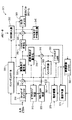
図3を参照して、本発明が適用される例示的なビデオエンコーダは、参照符号300により示される。
With reference to FIG. 3, an exemplary video encoder to which the present invention is applied is indicated by
ビデオエンコーダ300は、結合器385の非反転入力と接続される出力を有するフレームオーダリングバッファ310を含む。結合器385の出力は、変換器及び量子化器325の第一の入力と接続される。変換器及び量子化器325の出力は、エントロピーコーダ345の第一の入力、並びに、逆変換器及び逆量子化器350の第一の入力と接続される。エントロピーコーダ345の出力は、結合器390の第一の非反転入力と接続される。結合器390の出力は、出力バッファ335の第一の入力と接続される。
エンコーダコントローラ305の第一の出力は、フレームオーダリングバッファ310の第二の入力、逆変換器及び逆量子化器350の第二の入力、ピクチャタイプ判定モジュール315の入力、マクロブロックタイプ(MB-type)判定モジュール320の入力、イントラ予測モジュール360の第二の入力、デブロッキングフィルタ365の第二の入力、動き補償器370の第一の入力、動き予測器375の第一の入力、及び参照画像バッファ380の第二の入力に接続される。
The first output of the
エンコーダコントローラ305の第二の出力は、SEI(Supplemental Enhancement Information)挿入器330の第一の入力、変換器及び量子化器325の第二の入力、エントロピーコーダ345の第二の入力、出力バッファ335の第二の入力、SPS(Sequence Parameter Set)及びPPS(Picture Parameter Set)挿入器340の入力と接続される。
The second output of the
ピクチャタイプ判定モジュール315の第一の出力は、フレームオーダリングバッファ310の第三の入力と接続される。ピクチャタイプ判定モジュール315の第二の出力は、マクロブロックタイプ判定モジュール320の第二の入力と接続される。
A first output of the picture
SPS(Sequence Parameter Set)及びPPS(Picture Parameter Set)挿入器340の出力は、結合器390の第三の非反転入力に接続される。
The output of the SPS (Sequence Parameter Set) and PPS (Picture Parameter Set)
逆量子化器及び逆変換器350の出力は、結合器319の第一の非反転入力に接続される。結合器319の出力は、イントラ予測モジュール360の第一の入力とデブロッキングフィルタ365の第一の入力と接続される。デブロッキングフィルタ365の出力は、参照画像バッファ380の第一の入力と接続される。参照画像バッファ380の出力は、動き予測器375の第二の入力と接続される。動き予測器375の第一の出力は、動き補償器370の第二の入力と接続される。動き予測器375の第二の出力は、エントロピー符号化器345の第三の入力と接続される。
The output of the inverse quantizer and
動き補償器370の出力は、スイッチ397の第一の入力に接続される。イントラ予測モジュール360の出力は、スイッチ397の第二の入力と接続される。マクロブロックタイプ判定モジュール320の出力は、スイッチ397の第三の入力と接続される。スイッチ397の第三の入力は、スイッチの「データ」入力が(制御入力、すなわち第三の入力に比較して)動き補償器370又はイントラ予測モジュール360により供給されるか否かを判定する。スイッチ397の出力は、結合器319の第二の非反転入力と結合器385の反転入力に接続される。
The output of
フレームオーダリングバッファ310及びエンコーダコントローラ305の入力は、入力ピクチャ301を受けるために、エンコーダ300の入力として利用可能である。さらに、SEI(Supplemental Enhancement Information)挿入器330の入力は、メタデータを受けるため、エンコーダ300の入力として利用可能である。出力バッファ335の出力は、ビットストリームを出力するため、エンコーダ300の出力として利用可能である。
The inputs of the
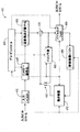
図4を参照して、本発明が適用される例示的なビデオデコーダは、参照符号400により示される。
Referring to FIG. 4, an exemplary video decoder to which the present invention is applied is indicated by
ビデオデコーダ400は、エントロピーデコーダ445の第一の入力と接続される出力を有する入力バッファ410を含む。エントロピーデコーダ445の第一の出力は、逆変換器及び逆量子化器450の第一の入力と接続される。逆変換器及び逆量子化器450の出力は、結合器425の第二の非反転入力と接続される。結合器425の出力は、デブロッキングフィルタ465の第二の入力及びイントラ予測モジュール460の第一の入力と接続される。デブロッキングフィルタ465の第二の出力は、参照画像バッファ480の第一の入力と接続される。参照画像バッファ480の出力は、動き補償器470の第二の入力と接続される。
エントロピーデコーダ445の第二の出力は、動き補償器470の第三の入力及びデブロッキングフィルタ465の第一の入力と接続される。エントロピーデコーダ445の第三の出力は、デコーダコントローラ405の入力と接続される。デコーダコントローラ405の第一の出力は、エントロピーデコーダ445の第二の入力と接続される。デコーダコントローラ405の第二の出力は、逆変換器及び逆量子化器450の第二の入力と接続される。デコーダコントローラ405の第三の出力は、デブロッキングフィルタ465の第三の入力と接続される。デコーダコントローラ405の第四の出力は、イントラ予測モジュール460の第二の入力、動き補償器470の第一の入力、参照画像バッファ480の第二の入力と接続される。
The second output of the
動き補償器470の出力は、スイッチ497の第一の入力と接続される。イントラ予測モジュール460の出力は、スイッチ497の第二の入力と接続される。スイッチ497の出力は、結合器425の第一の非反転入力と接続される。
The output of the
入力バッファ410の入力は、入力ビットストリームを受けるため、デコーダ400の入力として利用可能である。デブロッキングフィルタ465の第一の出力は、出力ピクチャを出力するため、デコーダ400の出力として利用可能である。
The input of the
本発明によれば、圧縮されたビデオビットレートを低減するためにデータ刈り取りを行い、同時に、デコーダ側での復号化及び再構成されたピクチャの非常に高画質を維持する新たなスキームが提案される。実施の形態に関する更なる詳細では、オリジナルの画像/ピクチャは、圧縮の前に小さなサイズに刈り取られ、次いで、復号化の後にそれらの本来のサイズに補間される。この補間は、それらの本来のサイズにビデオ画像/ピクチャを戻すため、データ刈り取りステップの間にどの線、セグメント又は領域が刈り取られたかに関する情報を使用する。刈り取りは、幾つかの可能性のある評価スキームのうちの1つに従って、空間領域において、線、セグメント及び/又は領域をドロップすることで符号化の前に行われ、次いで、空間領域にビットストリームを復号化した後に、これらの線、セグメント及び/又は領域が復元される。実施の形態では、その本来のサイズに復号化されたピクチャを再構成するため、エッジに向けられた補間が利用される。画像/ビデオピクチャにおける残りの画素をフィルタリングするのを回避するので、再構成されたピクチャは、低ビットレートから高画質を達成することができる。 In accordance with the present invention, a new scheme is proposed that performs data pruning to reduce the compressed video bit rate and at the same time maintains the very high picture quality of the decoded and reconstructed pictures at the decoder side. The In further details regarding the embodiments, the original images / pictures are trimmed to a small size before compression and then interpolated to their original size after decoding. This interpolation uses information about which lines, segments or regions have been pruned during the data pruning step to return the video images / pictures to their original size. The pruning is performed before encoding by dropping lines, segments and / or regions in the spatial domain according to one of several possible evaluation schemes, and then the bitstream in the spatial domain These lines, segments and / or regions are restored after decoding. In an embodiment, interpolation directed at the edge is used to reconstruct a picture decoded to its original size. Since it avoids filtering the remaining pixels in the image / video picture, the reconstructed picture can achieve high image quality from a low bit rate.
1実施の形態では、データ刈り取りは、行又は列のみがドロップされ、従って1方向におけるアップサンプリングのみがこれらの領域で必要とされるような方式で実行される。係る文脈で記載されるが、本発明の精神を維持しつつ、符号化の前に空間領域においてセクションをドロップする他の手段が使用される場合があることが当業者にとって明らかであろう。したがって、ドロップされるラインは、先の記載に限定されないが、列又は行である場合がある。たとえば、ドロップされるラインは、斜線である場合があり、又は、直線の代わりに及び/又は直線に加えて非線形の曲線である場合がある。さらに、同じ原理を当てはめることができ、刈り取られる必須のユニットは、空間領域の直線又は曲線ではなく、むしろセクション又は領域である点で本発明の範囲に含まれる。従って、直線の文脈で本実施の形態で提供される本発明の記載は、直線のみに本発明の範囲を制限するものではなく、符号化の前にドロップされる(そして結果的に復号化の後に復元される)べき空間領域における直線、曲線、セクション及び/又は領域の選択に限定されるものではない。従って、本実施の形態で提供される本発明の教示が与えられると、本発明のこれらの変形及び他の変形例が創作され、本発明の精神を維持しつつ、当業者により容易に実現可能である。本実施の形態で使用される用語「領域」は、1以上の直線、曲線、セクション及び/又は領域を表す場合があることを理解されたい。 In one embodiment, data pruning is performed in such a way that only rows or columns are dropped, so only upsampling in one direction is required in these regions. Although described in that context, it will be apparent to those skilled in the art that other means of dropping sections in the spatial domain may be used prior to encoding while maintaining the spirit of the present invention. Thus, the dropped lines are not limited to the previous description, but may be columns or rows. For example, the dropped line may be a diagonal line, or may be a non-linear curve instead of and / or in addition to a straight line. Furthermore, the same principle can be applied and the essential units to be trimmed are within the scope of the present invention in that they are sections or regions rather than straight lines or curves in the spatial domain. Thus, the description of the invention provided in this embodiment in the context of a straight line does not limit the scope of the invention to a straight line only, but is dropped before encoding (and consequently decoding) It is not limited to the selection of lines, curves, sections and / or regions in the spatial region to be restored later. Accordingly, given the teachings of the present invention provided in this embodiment, these and other variations of the present invention have been created and can be readily implemented by those skilled in the art while maintaining the spirit of the present invention. It is. It should be understood that the term “region” as used in this embodiment may represent one or more straight lines, curves, sections and / or regions.
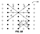
例示する目的で、新たなエッジに向けられた補間(NEDI: New Edge-Directed Interpolation, NEDI-4)を補間のためにどのように適合させるかに焦点が向けられる。図5Aを参照して、NEDI-4及びNEDI-8に関する高次のエッジに向けられた補間のモデルパラメータは、参照符号300により示される。この図に示されるように、5点形の準格子を使用した2つのパスが実行される。第一のパスでは、任意の4つの最も近い低解像度の画素の交点にある高解像度の画素は、適応型の4次の補間器を使用することで、それら最も近い画素から補間される。残りの高解像度の画素は、第一のパスにおける低解像度の画素と補間された画素とを使用して、第二のパスにおいて同じアルゴリズムで補間される。補間器の高解像度のモデルパラメータは、低解像度のモデルパラメータから予測される。
For purposes of illustration, the focus is on how to adapt New Edge-Directed Interpolation (NEDI-4) for interpolation. Referring to FIG. 5A, model parameters for interpolation directed to higher order edges for NEDI-4 and NEDI-8 are indicated by
[データ刈り取り]
データ刈り取りは、ピクチャにおけるラインをドロップすることで実現される。特定のケースでは、ラインは直線である。そのケースでは、ラインは、行又は列であるか、(図6に示されるような)方向をもつ任意の直線である。図6を参照して、任意のラインをドロップすることによるデータ刈り取りの例は、参照符号600により示される。データ刈り取り600は、フレーム610、刈り取られたライン620及び刈り取られた曲線630を含む。
[Data pruning]
Data pruning is realized by dropping a line in a picture. In certain cases, the line is a straight line. In that case, the line is a row or column or any straight line with a direction (as shown in FIG. 6). With reference to FIG. 6, an example of data pruning by dropping an arbitrary line is indicated by
図7を参照して、1つのフレームにおける列及び行をドロップすることによるデータ刈り取りの例は、参照符号700により示される。データ刈り取り700は、フレーム710、ドロップされた列720、及びドロップされた行730を含む。
With reference to FIG. 7, an example of data pruning by dropping columns and rows in one frame is indicated by
図8を参照して、全体のグループオブピクチャ(GOP)及び/又はシーンについて同じ列及び行をドロップすることによるデータ刈り取りの例は、参照符号800により示される。データ刈り取り800は、最初のフレーム810、中間のフレーム820及び最後のフレーム830、ドロップされた行840、及びドロップされた列850を含む。
With reference to FIG. 8, an example of data pruning by dropping the same column and row for the entire group of pictures (GOP) and / or scene is indicated by
図9Aを参照して、公知のAkiyoシーケンスの最初のフレームにおけるドロップされた列及び行を示すラインは、参照符号900により示される。図9Bを参照して、図9Aの例に対応する刈り取られたフレームは、参照符号950により示される。
Referring to FIG. 9A, a line indicating a dropped column and row in the first frame of a known Akiyo sequence is indicated by
デコーダは失われた画素を補間する必要があるので、デコーダでドロップされたラインの位置を知ることが必要である。ドロップされたラインの画素の位置を指示することと、このドロップされたラインを把握するオーバヘッドとの間にトレードオフが存在する。1実施の形態では、ラインを示すオーバヘッドを大幅に低減するため、列のみ、行のみがドロップされる。このケースでは、記録するために行/列当たり1ビットが使用され、従って(1フレームにおける列及び行をドロップする図7、1GOP/シーンにおける列及び行をドロップする図8、白線がドロップされた列及び行を示す図9A、及び刈り取られたフレームについて図9Bに見られるように)そのラインがドロップされるか否かが示される。別の実施の形態では、奇数ラインのみがドロップされ、偶数ラインは手付かずにされる。1実施の形態では、1GOP/シーンにおける全てのピクチャは、オーバヘッドを更に低減するために同じドロッピングパターンを有する。どのラインが最初にドロップされるかを判定するため、1実施の形態では、圧縮が関与しないこと、歪みの基準が使用されるものとする。最初に、最終的な目標が設定される。この目標は、歪み、画素をドロップするパーセンテージ、及び/又は複雑度の制約である。勿論、本実施の形態で提供される本発明の教示が与えられると、目標は、上記したものに限定されず、本発明の精神を維持しつつ、本発明に従って他の目標が使用される場合がある。1実施の形態では、1つの直線がドロップされることが想定され、圧縮を考慮することなしにドロップされた直線が補間される。次いで、補間された直線の平均平方誤差(MSE)が原画像における同じ直線に比較される。最小のMSEを有する直線が最初にドロップされるために選択される。別の実施の形態では、そのラインの歪みとビットレートの両者が考慮される。1実施の形態では、ラインのビットレートは、その分散を使用して近似される。 Since the decoder needs to interpolate the lost pixels, it is necessary to know the position of the line dropped by the decoder. There is a trade-off between indicating the pixel location of the dropped line and the overhead of grasping the dropped line. In one embodiment, only the columns and only the rows are dropped in order to significantly reduce the overhead that represents lines. In this case, 1 bit per row / column was used to record, therefore (FIG. 7, dropping columns and rows in one frame, FIG. 8, dropping columns and rows in a scene, white lines dropped) FIG. 9A showing the columns and rows, and whether the line is dropped (as seen in FIG. 9B for the pruned frame) is shown. In another embodiment, only odd lines are dropped and even lines are left untouched. In one embodiment, all pictures in a GOP / scene have the same dropping pattern to further reduce overhead. To determine which line is dropped first, in one embodiment, no compression is involved and a distortion criterion is used. First, a final goal is set. The goal is distortion, percentage dropping pixels, and / or complexity constraints. Of course, given the teachings of the invention provided in this embodiment, the goals are not limited to those described above, and other goals may be used in accordance with the invention while maintaining the spirit of the invention. There is. In one embodiment, it is assumed that one straight line is dropped, and the dropped straight line is interpolated without considering compression. The mean square error (MSE) of the interpolated line is then compared to the same line in the original image. The straight line with the smallest MSE is selected to be dropped first. In another embodiment, both line distortion and bit rate are considered. In one embodiment, the bit rate of the line is approximated using its variance.
[最適なデータ刈り取りの実施の形態]
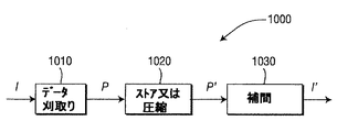
図10を参照して、データ刈り取りに基づいた圧縮の例示的なシステムは、参照符号1000により示される。システム1000は、データ刈り取り器1010、データストア又は圧縮器1020、及び補間器1030を含む。個別のエレメントとして示されているが、データ刈り取り器1010、データストア又は圧縮器1020、又は補間器1030の1以上が統合されたエレメントに結合される場合がある。たとえば、1実施の形態では、データ刈り取り器1010は、データストア又は圧縮器1020に含まれる場合がある。データストア又は圧縮器1020は、本発明の目的について、エンコーダであると考えられる。サイズM×NのオリジナルフレームIは、より小さなサイズ(M−Mp)×(N−Np)のフレームPに刈り取られ、この場合、Mp及びNpは、それぞれドロップされた行及び列の数である。データ刈り取りの目的は、記憶又は圧縮されたフレームP’を表すビット数を低減することである。次いで、P’は、本来のフレームサイズに再構成するためにI’に補間される。本実施の形態で考慮される圧縮ステージは、MPEG-4AVC規格のコーデックであり、図3に示されるエンコーダと図4に示されるデコーダである。しかし、先に述べたように、本発明は、MPEG-4AVC規格にのみ限定されるものではなく、従って、本発明の精神を維持しつつ、他のビデオ符号化規格、勧告、及び、その拡張に適用される場合がある。
[Optimum data pruning embodiment]
With reference to FIG. 10, an exemplary system for compression based on data pruning is indicated by
偶数行及び列のみがドロップされることが考慮され、奇数行及び列は、後の補間について保持される。図11を参照して、データ刈り取り段階の例示的なシステムは、参照符号1100により示される。システム1100は、間引き器1110及び補間器1120を含む。データ刈り取り段階では、それぞれ列のみのドロップ、行のみのドロップ、及び行と列の両者のドロップを示すケースについて1×2、2×1及び2×2の割合で、原フレームIは、間引き器1110により低解像度(LR)フレームIlに間引きされる。次いで、フレームIlは、補間器1120により高解像度(HR)フレームIhに補間される。補間のため、再構成されたフレームは、その原フレームとは異なる。Iにおける対応する行及び列に比較して最小のエラーを有するIhにおける行及び列は、ドロップされるように選択される。平均平方誤差(MSE)は、IhとIとの間の平均平方誤差として定義される。
Considering that only even rows and columns are dropped, odd rows and columns are retained for later interpolation. With reference to FIG. 11, an exemplary system for the data pruning stage is indicated by
目標となるMSEmaxが与えられると、全体のMSEをMSEmax未満に保持しつつ、大部分の画素をドロップするためにデータ刈り取りが最適化される。ドロップされる行及び列の位置は、αm及びαnによりそれぞれ示される。αiの値が1である場合、i番目の偶数ライン(行又は列)がドロップされ、さもなければ、保持される。これらのインジケータは、符号化されたビットストリームにおけるサイド情報として記憶される。1つのドロップされた直線の平均平方直線誤差(MSLE)は、その直線のみの画素についてIhとIとの間の平均平方誤差として定義される。より小さいMSLEをもつ直線は、より高いMSLEをもつ直線よりもドロップされるべき高い優先度を有する。最小のMSLEをもつMp行及びNp列がドロップされ、これらの直線の最大のMSLEがMSLEmaxであるとする。全体のMSEは、全てのドロップされた画素の平均されたMSEとなる。MSEの上限は、たとえばドロップされた行数Mp、ドロップされた列数Np、及びMSLEmaxに基づいて達成される。この上限は、最適なデータ刈り取りスキームを発見するために条件として、MSEmax未満である。 Given a target MSEmax, data pruning is optimized to drop most pixels while keeping the overall MSE below MSEmax. The location of the dropped row and column is indicated by α m and α n , respectively. If the value of α i is 1, the i th even line (row or column) is dropped, otherwise it is retained. These indicators are stored as side information in the encoded bitstream. The mean square line error (MSLE) of a single dropped line is defined as the mean square error between I h and I for pixels of that line only. A straight line with a smaller MSLE has a higher priority to be dropped than a straight line with a higher MSLE. Assume that M p rows and N p columns with the smallest MSLE are dropped and the largest MSLE of these lines is MSLEmax. The overall MSE is the averaged MSE of all dropped pixels. The upper limit of MSE is achieved based on, for example, the number of dropped rows M p , the number of dropped columns N p , and MSLEmax. This upper limit is less than MSEmax as a condition for finding the optimal data pruning scheme.
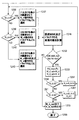
図12A及び図12Bを参照して、最適なデータ刈り取りの例示的な方法は、参照符号1200により示される。本方法1200は、開始ブロック1201を含み、この開始ブロックは、機能ブロック1203に制御を移す。機能ブロック1203は、フレーム又はGOPを入力し、機能ブロック1206、機能ブロック1209及び機能ブロック1212に制御を移す。機能ブロック1206は、偶数行を除き、機能ブロック1215に制御を移す。機能1215は、たとえばNEDI-6に基づいて補間を行い、機能ブロック1224に制御を移す。機能ブロック1224は、オリジナルの行と再構成された行との間の誤差を発見し(1)、機能ブロック1233に制御を移す。
With reference to FIGS. 12A and 12B, an exemplary method of optimal data pruning is indicated by
機能ブロック1209は、偶数列を除去し、機能ブロック1218に制御を移す。機能ブロック1218は、たとえばNEDI-6に基づいて補間を実行し、機能ブロック1227に制御を移す。機能ブロック1227は、オリジナルの列と再構成された列との間の誤差を発見し(2)、機能ブロック1233に制御を移す。
The
機能ブロック1212は、偶数行及び列を除去し、機能ブロック1221に制御を移す。機能ブロック1221は、たとえばNEDI-8に基づいて補間を行い、機能ブロック1230に制御を移す。機能ブロック1230は、オリジナルの行/列と再構成された行/列との間の誤差を発見し(3)、機能ブロック1233に制御を移す。
The
機能ブロック1233は、ドロップされた行の番号(No)M_d=0を設定し、ドロップされた列の番号N_d=0を設定し、最大のドロップされた画素Pel=0を設定し、及び判定ブロック1236に制御を移す。判定ブロック1236は、M_d=0であるか否かを判定する。M_d=0であると判定した場合、機能ブロック1242に制御を移す。さもなければ、判定ブロック1239に制御を移す。
The
機能ブロック1242は、(1)における最小の誤差、すなわち機能ブロック1224あたり計算された誤差をもつN_dの行をドロップするために選択し、機能ブロック1246に制御を移す。機能ブロック1246は、誤差MSE及びドロップされた画素数Pelを計算し、判定ブロック1252に制御を移す。判定ブロック1252は、MSE<MSE_max及びPel>Pel_maxであるか否かを判定する。MSE<MSE_max及びPel>Pel_maxであると判定した場合、機能ブロック1255に制御を移す。さもなければ、機能ブロック1270に制御を移す。
The
機能ブロック1255は、Pel_max=Pelを設定し、M_d_opt=M_dを設定し、N_d_opt=N_dを設定し、機能ブロック1258に制御を移す。機能ブロック1258は、N_d<Nであるか否かを判定する。N_d<Nであると判定した場合、機能ブロック1264に制御を移す。さもなければ、機能ブロック1261に制御を移す。
The
機能ブロック1261は、M_d<Mであるか否かを判定する。M_d<Mであると判定した場合、機能ブロック1267に制御を移す。さもなければ、機能ブロック1270に制御を移す。
The
判定ブロック1239は、N_d=0であるか否かを判定する。N_d=0であると判定した場合、機能ブロック1245に制御を移す。さもなければ、機能ブロック1249に制御を移す。
The
機能ブロック1245は、(2)における最小の誤差、すなわち機能ブロック1227で計算された誤差をもつM_dの列をドロップするために選択し、機能ブロック1246に制御を移す。
The
機能ブロック1249は、(3)における最小の誤差、すなわち機能ブロック1230で計算された誤差をもつM_d列及びN_d行をドロップするために選択し、機能ブロック1046に制御を移す。
The
機能ブロック1270は、M_d_opt及びN_d_optを出力し、終了ブロック1299に制御を移す。
The
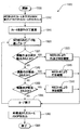
図13を参照して、最適なデータ復元の例示的な方法は、参照符号1300により示される。本方法1300は、開始ブロック1305を含み、この開始ブロックは、機能ブロック1310に制御を移す。機能ブロック1310は、刈り取られたフレーム及び/又はグループオブピクチャ(GOP)、並びにドロップされたフレームのリストを入力し、機能ブロック1315に制御を移す。機能ブロック1315は、フレームをそれらの本来のサイズに変更し、ループリミットブロック1320に制御を移す。ループリミットブロック1320は、刈り取られたデータについてループし、判定ブロック1325に制御を移す。判定ブロック1325は、偶数行及び列が除かれているか否かを判定する。偶数行及び列が除かれていると判定した場合、機能ブロック1330に制御を移す。さもなければ、判定ブロック1340に制御を移す。
With reference to FIG. 13, an exemplary method for optimal data recovery is indicated by
機能ブロック1330は、行及び列をNEDI-8により補間し、ループリミットブロック1335に制御を移す。
The
ループリミットブロック1335は、ループを終了し、機能ブロック1360に制御を移す。機能ブロック1360は、再構成されたフレーム/GOPを出力し、終了ブロック1399に制御を移す。
判定ブロック1340は、偶数行が除かれているか否かを判定する。偶数行が除かれていると判定した場合、機能ブロック1345に制御を移す。さもなければ、判定ブロック1350に制御を移す。
機能ブロック1345は、その行をNEDI-6で補間し、ループリミットブロック1335に制御を移す。
The
判定ブロック1350は、偶数列が除かれているか否かを判定する。偶数列が除かれていると判定した場合、機能ブロック1355に制御を移す。さもなければ、ループリミットブロック1335に制御を移す。
機能ブロック1355は、その列をNEDI-6で補間し、ループリミットブロック1335に制御を移す。
The
[高次のエッジに向けられた補間]
補間により、同じ又は一時的に関連するフレームの周辺の画素からかけている画素を推定/充填することができる方法が意図される。係る方法は、それらの周囲から欠けている画素のホールを充填する、Bi-Cubic方法のような古典的な補間、NEDIのような新たな方法、修復(inpainting)のような他の種類の方法とすることができる。勿論、本発明に係る補間は、先に記載した補間技術に限定されるものではなく、本発明の精神を維持しつつ、他の補間技術が使用される場合もある。
[Interpolation towards higher-order edges]
A method is contemplated by which interpolation can estimate / fill pixels that are multiplying from pixels around the same or temporarily related frame. Such methods fill the missing pixel holes from their surroundings, classical interpolation such as the Bi-Cubic method, new methods such as NEDI, and other types of methods such as inpainting It can be. Of course, the interpolation according to the present invention is not limited to the interpolation technique described above, and other interpolation techniques may be used while maintaining the spirit of the present invention.
デコーダでの補間について、高次のエッジに向けられた補間を適用することが提案され、従って更に多くの方法に適合させることができる。本発明の方法は、低解像度の画像の分散に関連する従来のアプローチで記載されたものとは異なり、この従来のアプローチは、4つの隣接する画素を使用し、2×2のアップサイジング比についてのみ適用される。本発明は、これを提案されるデータ刈り取りスキームについて使用されるように適合させる。実施の形態では、1次元(行のみ又は列のみ)及び2次元(行と列の両者)のそれぞれにおけるラインをドロップするケースについて使用される、6次及び8次のエッジに向けられた補間が使用される。 For interpolation at the decoder, it has been proposed to apply interpolation directed to higher-order edges and can therefore be adapted to many more methods. The method of the present invention differs from that described in the conventional approach related to the dispersion of low resolution images, which uses four adjacent pixels and for a 2 × 2 upsizing ratio. Only applies. The present invention adapts this to be used for the proposed data pruning scheme. In an embodiment, interpolation directed to the 6th and 8th order edges used for the case of dropping lines in one dimension (row only or column only) and two dimension (both row and column) respectively. used.
[実施の形態:NEDI-6]
列のみをドロップするアルゴリズムが記載される。これは、同じアルゴリズムを列のみをドロップするケース及び行のみをドロップするケースについて適用することができるからである。はじめに、原フレームIにおける奇数列に対応するP’の列は、サイズM×(N/2)の低解像度フレームPl’を形成するために抽出される。Pl’の列は、サイズM×NのHRフレームPh’の奇数列にマッピングされる。Ph’の偶数列は、本実施の形態で説明される6次の補間により奇数列から補間される。
[Embodiment: NEDI-6]
An algorithm for dropping only the columns is described. This is because the same algorithm can be applied to the case of dropping only columns and the case of dropping only rows. First, P ′ columns corresponding to odd columns in the original frame I are extracted to form a low resolution frame P l ′ of size M × (N / 2). The column of P l ′ is mapped to the odd column of the HR frame P h ′ of size M × N. The even columns of P h ′ are interpolated from the odd columns by the sixth-order interpolation described in the present embodiment.
補間される画素は、図5Bに示される重み付けされた6つの隣接する周辺の画素の合計である。図5Bを参照して、NEDI-6に関連する高次のエッジに向けられた補間のモデルパラメータは、参照符号500により示される。これらの重みは、高解像度のフレームのモデルパラメータである。最適なモデルパラメータは、モデルパラメータがローカルウィンドウにおいて一定であるという前提で、補間された画素とオリジナルの画素との間のMSEを最小にすることで得られる。幾何学的な二重性の前提を適用して、モデルパラメータは、異なるスケールについて一定であると考えられ、低解像度画素から推定される。図5Bに示されるように、低解像度フレームのモデルパラメータは、オリジナルの画素と補完された画素とを利用可能であると共に、それらの間の誤差を最小にすることで得られる。次いで、これらの低解像度モデルパラメータは、欠けている高解像度の画素を補間するために高解像度のモデルパラメータとして使用される。最後に、列インジケータは、最終的に再構成されたフレームを形成するため、圧縮された刈り取られたフレーム又は補間されたフレームから画素を選択するために使用される。列のインジケータの値が1である場合、再構成された列は、補間されたフレームから取得される。さもなければ、列のインジケータの値が0である場合、再構成された列は、圧縮された刈り取られたフレームから取得される。
The interpolated pixel is the sum of the 6 weighted neighboring pixels shown in FIG. 5B. Referring to FIG. 5B, model parameters for interpolation directed to higher order edges associated with NEDI-6 are indicated by
[実施の形態:NEDI-8]
NEDI-6と同様に、原フレームIにおけるダウンサンプリング率2×2の低解像度画素に対応するP’における画素は、サイズ(M/2)×(N/2)のLRフレームPl’を形成するために抽出される。補間は、第1回についてNEDI-4を使用して実行され、第2回についてNEDI-8を使用して実行される。第2ラウンドにおける全ての8つの隣接する画素が利用可能となると共に、4つの方向から余分の情報を得るためにNEDI-8が実現される。この第二ラウンドの利点は、モデルパラメータがその高解像度画素から直接的に予測され、従って、NEDI-4のオーバフィッティング問題が緩和される。NEDI-8は、一貫したものとするため、全ての欠けている高解像度画素に適用される。HRスケールの4次のモデルパラメータh4及び8次のモデルパラメータh8は、図3Aに示される。最適値h8は、NEDI-6について採用されたものに同様のアルゴリズムにより計算される。
[Embodiment: NEDI-8]
Similar to NEDI-6, the pixels at P ′ corresponding to the low resolution pixels with the downsampling rate of 2 × 2 in the original frame I form the LR frame P 1 ′ of size (M / 2) × (N / 2). To be extracted. Interpolation is performed for the first time using NEDI-4 and for the second time using NEDI-8. All eight adjacent pixels in the second round are available and NEDI-8 is implemented to obtain extra information from the four directions. The advantage of this second round is that model parameters are predicted directly from their high resolution pixels, thus mitigating the NEDI-4 overfitting problem. NEDI-8 applies to all missing high resolution pixels to be consistent. The HR scale fourth order model parameter h 4 and the eighth order model parameter h 8 are shown in FIG. 3A. The optimal value h 8 is calculated by an algorithm similar to that adopted for NEDI-6.
以下、本発明の多くの付随する利点/特徴の幾つかに関する説明が与えられ、そのうちの幾つかは、上述された。たとえば、1つの利点/特徴は、符号化による圧縮の前に、又は符号化による圧縮に備えて、あるピクチャを前処理するデータ刈り取り手段を有する装置である。データ刈り取り手段は、空間領域において該ピクチャにおける少なくとも1つの領域を選択的に除く。 The following is a description of some of the many attendant advantages / features of the present invention, some of which have been described above. For example, one advantage / feature is an apparatus having data pruning means that pre-processes a picture before compression by encoding or in preparation for compression by encoding. The data pruning means selectively removes at least one region in the picture in the spatial region.
別の利点/特徴は、上述されたデータ刈り取り手段を有する装置であり、データ刈り取り手段は、エンコーダに含まれる。 Another advantage / feature is an apparatus having the data pruning means described above, wherein the data pruning means is included in the encoder.
更に別の利点/特徴は、上述されたデータ刈り取り手段を有する装置であり、少なくとも1つの領域が除かれたピクチャを符号化するためにデータ刈り取り手段に結合されるエンコーダを更に有する。 Yet another advantage / feature is an apparatus having data pruning means as described above, further comprising an encoder coupled to the data pruning means for encoding a picture from which at least one region has been removed.
また、別の利点/特徴は、上述されたデータ刈り取り手段を有する装置であり、該ピクチャにおける少なくとも1つの領域の位置を示すサイド情報は、デコーダ又は他の装置に明示的又は暗黙的に送信される。 Another advantage / feature is an apparatus having the above-described data pruning means, wherein side information indicating the position of at least one region in the picture is transmitted explicitly or implicitly to a decoder or other apparatus. The
更に別の利点/特徴は、上述されたデータ刈り取り手段を有する装置であり、少なくとも1つの領域は、直線、非線形の曲線及び領域の少なくとも1つを含む。 Yet another advantage / feature is an apparatus having the data pruning means described above, wherein the at least one region includes at least one of a straight line, a non-linear curve, and a region.
さらに、別の利点/特徴は、上述されたデータ刈り取り手段を有する装置であり、偶数ラインのみ又は奇数ラインのみがデータ刈り取り器により除かれる。 Yet another advantage / feature is the apparatus having the data pruning means described above, wherein only even or odd lines are removed by the data pruner.
さらに、別の利点/特徴は、上述されたデータ刈り取り器を有する装置であり、ピクチャは、グループオブピクチャに含まれ、グループオブピクチャにおける全てのピクチャには、同じ除去のパターンが割り当てられる。 Yet another advantage / feature is an apparatus having the data reaper described above, where pictures are included in a group of pictures, and all pictures in the group of pictures are assigned the same removal pattern.
また、別の利点/特徴は、上述されたデータ刈り取り器を有する装置であり、選択的に除去された少なくとも1つの領域は、画像の歪みの基準、レート歪みの基準、ドロップされた画素の基準及び複雑度の基準の少なくとも1つの評価に応じて決定される。 Another advantage / feature is an apparatus having a data reaper as described above, wherein the at least one selectively removed region is an image distortion criterion, a rate distortion criterion, a dropped pixel criterion. And at least one evaluation of the complexity criteria.
さらに、別の利点/特徴は、上述されたデータ刈り取り器を有する装置であり、1次元における少なくとも1つの領域を除去するために6次の補間が使用され、2次元における少なくとも1つの領域を除去するために8次の補間が使用される。 In addition, another advantage / feature is a device having a data reaper as described above, wherein sixth-order interpolation is used to remove at least one region in one dimension and removes at least one region in two dimensions. In order to do so, an 8th order interpolation is used.
本発明のこれらの特徴及び利点、並びに他の特徴及び利点は、本実施の形態での教示に基づいて当業者により容易に確かめられる場合がある。本発明の教示は、ハードウェア、ソフトウェア、ファームウェア、特定用途向けプロセッサ、又はそれらの組み合わせといった様々な形式で実現されることを理解されたい。 These and other features and advantages of the present invention may be readily ascertainable by those skilled in the art based on the teachings of the present embodiments. It should be understood that the teachings of the present invention can be implemented in various forms, such as hardware, software, firmware, application specific processors, or combinations thereof.
最も好ましくは、本発明の教示は、ハードウェアとソフトエアの組み合わせとして実現される。さらに、ソフトウェアは、プログラムストレージユニットで実施されるアプリケーションプログラムとして実現される場合がある。アプリケーションプログラムは、任意の適切なアーチテクチャを備えるコンピュータにアップロードされて実行される場合がある。好ましくは、コンピュータは、1以上の中央処理装置(CPU)、ランダムアクセスメモリ(RAM)及び入力/出力(I/O)インタフェースのようなハードウェアを有するコンピュータプラットフォームで実現される。また、コンピュータプラットフォームは、オペレーティングシステム又はマイクロコードを含む場合がある。本実施の形態で記載された様々なプロセス及び機能は、CPUにより実行される場合がある、マイクロプログラムの一部であるか又はアプリケーションプログラムの一部、或いはそれらの組み合わせである場合がある。さらに、様々な周辺装置は、更なるデータストレージユニット及びプリンティングユニットのようなコンピュータプラットフォームに接続される場合がある。 Most preferably, the teachings of the present invention are implemented as a combination of hardware and software. Furthermore, the software may be realized as an application program executed in the program storage unit. The application program may be uploaded and executed on a computer with any suitable architecture. Preferably, the computer is implemented on a computer platform having hardware such as one or more central processing units (CPUs), random access memory (RAM) and input / output (I / O) interfaces. A computer platform may also include an operating system or microcode. Various processes and functions described in this embodiment may be part of a microprogram or part of an application program, or a combination thereof, which may be executed by a CPU. In addition, various peripheral devices may be connected to a computer platform such as an additional data storage unit and a printing unit.
添付図面に示されるシステムコンポーネント及び方法の幾つかは、ソフトウェアで好ましくは実現されるため、システムコンポーネント又はプロセス機能ブロック間の実際の接続は、本発明がプログラムされるやり方に依存して異なる場合がある。本実施の形態における教示が与えられると、当業者であれば、本発明のこれらの実現又はコンフィギュレーション、及び類似の実現又はコンフィギュレーションを創作することができるであろう。 Since some of the system components and methods shown in the accompanying drawings are preferably implemented in software, the actual connections between system components or process functional blocks may vary depending on how the invention is programmed. is there. Given the teachings in this embodiment, one of ordinary skill in the art will be able to create these and similar implementations or configurations of the present invention.
例示的な実施の形態が添付図面を参照して本実施の形態で記載されたが、本発明はそれら正確な実施の形態に限定されるものではなく、様々な変更及び変形が本発明の範囲及び精神から逸脱することなしに当業者により実施されることを理解されたい。全ての係る変形及び変更は、特許請求の範囲で述べた本発明の範囲に含まれることが意図される。 Although exemplary embodiments have been described in the present embodiments with reference to the accompanying drawings, the present invention is not limited to the exact embodiments, and various changes and modifications can be made within the scope of the present invention. It should be understood that this can be done by those skilled in the art without departing from the spirit. All such variations and modifications are intended to be included within the scope of the present invention as set forth in the appended claims.
Claims (36)
前記データ刈り取り手段は、前記ピクチャにおける少なくとも1つの領域を空間領域において選択的に除去する、
ことを特徴とする装置。 An apparatus comprising data pruning means for preprocessing a picture in preparation for compression by encoding before compression by encoding,
The data pruning means selectively removes at least one region in the picture in a spatial region;
A device characterized by that.
請求項1記載の装置。 The data pruning means is included in an encoder.
The apparatus of claim 1.
請求項1記載の装置。 An encoder coupled to the data pruning means for encoding the picture from which the at least one region has been removed;
The apparatus of claim 1.
請求項1記載の装置。 Side information indicating the position of the at least one region in the picture is explicitly or implicitly sent to a decoder or other device;
The apparatus of claim 1.
請求項5記載の装置。 The at least one region is at least one of a straight line, a non-linear curve and a region;
The apparatus of claim 5.
請求項1記載の装置。 By the data mowing means, only even-numbered straight lines or only odd-numbered straight lines are removed.
The apparatus of claim 1.
請求項1記載の装置。 The picture is included in a group of pictures, and all the pictures in the group of pictures are assigned the same removal pattern.
The apparatus of claim 1.
請求項1記載の装置。 The at least one region that is selectively removed is determined in response to at least one evaluation of an image distortion criterion, a rate distortion criterion, a dropped pixel criterion, and a complexity criterion.
The apparatus of claim 1.
請求項1記載の装置。 Sixth-order interpolation is used to remove the at least one region that is one-dimensional, and eighth-order interpolation is used to remove the at least one region that is two-dimensional.
The apparatus of claim 1.
前記前処理するステップは、プロセッサを有するデータ刈り取り手段が、前記ピクチャにおける少なくとも1つの領域を空間領域において選択的に除去するステップを含む、
ことを特徴とする方法。 A method comprising the step of pre-processing a picture in preparation for compression by encoding prior to compression by encoding,
The preprocessing step includes a step of data pruning means having a processor selectively removing at least one region in the picture in a spatial region.
A method characterized by that.
請求項10記載の方法。 The method is executed by an encoder.
The method of claim 10.
請求項10記載の方法。 Encoding the picture from which the at least one region has been removed, further comprising:
The method of claim 10.
請求項10記載の方法。 Side information indicating the position of the at least one region in the picture is explicitly or implicitly sent to a decoder or other device;
The method of claim 10.
請求項10記載の方法。 The at least one region is at least one of a straight line, a non-linear curve and a region;
The method of claim 10.
請求項10記載の方法。 By the preprocessing step, only even-numbered straight lines or only odd-numbered straight lines are removed.
The method of claim 10.
請求項10記載の方法。 The picture is included in a group of pictures, and all the pictures in the group of pictures are assigned the same removal pattern.
The method of claim 10.
請求項10記載の方法。 The at least one region that is selectively removed is determined in response to at least one evaluation of an image distortion criterion, a rate distortion criterion, a dropped pixel criterion, and a complexity criterion.
The method of claim 10.
請求項10記載の方法。 Sixth-order interpolation is used to remove the at least one region that is one-dimensional, and eighth-order interpolation is used to remove the at least one region that is two-dimensional.
The method of claim 10.
ことを特徴とする装置。 Following decompression by decoding, the decompressed picture is received and the at least one in the decompressed picture is based on information indicating that at least one region has been removed prior to the previous encoding process. Data restoration means for post-processing the decompressed picture by selectively restoring one area in a spatial area;
A device characterized by that.
請求項19記載の装置。 The data restoration means is included in a decoder.
The apparatus of claim 19.
請求項19記載の装置。 A decoder coupled to the data decompression means for decoding the picture from which the at least one region has been removed;
The apparatus of claim 19.
請求項19記載の装置。 The data restoration means receives side information indicating a position of the at least one region in the picture;
The apparatus of claim 19.
請求項19記載の装置。 The at least one region is at least one of a straight line, a non-linear curve and a region;
The apparatus of claim 19.
請求項19記載の装置。 By the data restoration means, only even-numbered straight lines or only odd-numbered straight lines are restored,
The apparatus of claim 19.
請求項19記載の装置。 The picture is included in a group of pictures, and all the pictures in the group of pictures are assigned the same removal pattern.
The apparatus of claim 19.
請求項19記載の装置。 Sixth-order interpolation is used to restore the at least one region that is one-dimensional, and eighth-order interpolation is used to restore the at least one region that is two-dimensional.
The apparatus of claim 19.
以前に行われた符号化処理の前に少なくとも1つの領域が除去されたことを示す情報に基づいて、前記伸張されたピクチャにおける前記少なくとも1つの領域を空間領域において選択的に復元することで、プロセッサを有するデータ復元手段を使用して、前記伸張されたピクチャを後処理するステップと、
を含むことを特徴とする方法。 Receiving decompressed pictures following decompression by decoding;
Selectively restoring in the spatial domain the at least one region in the decompressed picture based on information indicating that at least one region has been removed prior to the encoding process performed previously; Post-processing the decompressed picture using data decompression means having a processor;
A method comprising the steps of:
請求項27記載の方法。 The method is included in a decoder,
28. The method of claim 27.
請求項27記載の方法。 Prior to the receiving step further comprising decoding the picture from which the at least one region has been removed,
28. The method of claim 27.
請求項27記載の方法。 The data restoration means receives side information indicating a position of the at least one region in the picture;
28. The method of claim 27.
請求項27記載の方法。 The at least one region is at least one of a straight line, a non-linear curve and a region;
28. The method of claim 27.
請求項27記載の方法。 By the post-processing step, only even-numbered straight lines or only odd-numbered straight lines are restored.
28. The method of claim 27.
請求項19記載の方法。 The picture is included in a group of pictures, and all the pictures in the group of pictures are assigned the same removal pattern.
The method of claim 19.
請求項27記載の方法。 Sixth-order interpolation is used to restore the at least one region that is one-dimensional, and eighth-order interpolation is used to restore the at least one region that is two-dimensional.
28. The method of claim 27.
符号化による圧縮の前に前処理された符号化されたピクチャを含み、
ピクチャにおける少なくとも1つの領域を空間領域において選択的に除去するように前記ピクチャが前処理される、
ことを特徴とするビデオ信号構造。 A video signal structure for video encoding,
Including an encoded picture that has been preprocessed prior to compression by encoding;
The picture is preprocessed to selectively remove at least one region in the picture in the spatial region;
A video signal structure characterized by that.
ピクチャにおける少なくとも1つの領域を空間領域において選択的に除去するように前記ピクチャが前処理される、
ことを特徴とするビデオ信号構造。 A recording medium storing encoded video signal data, including an encoded picture that has been preprocessed before compression by encoding,
The picture is preprocessed to selectively remove at least one region in the picture in the spatial region;
A video signal structure characterized by that.
Applications Claiming Priority (3)
| Application Number | Priority Date | Filing Date | Title |
|---|---|---|---|
| US9812508P | 2008-09-18 | 2008-09-18 | |
| US61/098,125 | 2008-09-18 | ||
| PCT/US2009/004950 WO2010033151A1 (en) | 2008-09-18 | 2009-09-01 | Methods and apparatus for video imaging pruning |
Related Child Applications (1)
| Application Number | Title | Priority Date | Filing Date |
|---|---|---|---|
| JP2013263937A Division JP5907941B2 (en) | 2008-09-18 | 2013-12-20 | Method and apparatus for trimming video images |
Publications (2)
| Publication Number | Publication Date |
|---|---|
| JP2012503416A true JP2012503416A (en) | 2012-02-02 |
| JP2012503416A5 JP2012503416A5 (en) | 2012-10-18 |
Family
ID=41582015
Family Applications (2)
| Application Number | Title | Priority Date | Filing Date |
|---|---|---|---|
| JP2011527796A Pending JP2012503416A (en) | 2008-09-18 | 2009-09-01 | Method and apparatus for trimming video images |
| JP2013263937A Active JP5907941B2 (en) | 2008-09-18 | 2013-12-20 | Method and apparatus for trimming video images |
Family Applications After (1)
| Application Number | Title | Priority Date | Filing Date |
|---|---|---|---|
| JP2013263937A Active JP5907941B2 (en) | 2008-09-18 | 2013-12-20 | Method and apparatus for trimming video images |
Country Status (8)
| Country | Link |
|---|---|
| US (1) | US9571857B2 (en) |
| EP (1) | EP2335419B1 (en) |
| JP (2) | JP2012503416A (en) |
| KR (3) | KR20160114186A (en) |
| CN (1) | CN102217314B (en) |
| BR (1) | BRPI0918044A2 (en) |
| TW (1) | TWI499310B (en) |
| WO (1) | WO2010033151A1 (en) |
Families Citing this family (20)
| Publication number | Priority date | Publication date | Assignee | Title |
|---|---|---|---|---|
| KR20110011361A (en) * | 2009-07-28 | 2011-02-08 | 삼성전자주식회사 | Apparatus and method for image data encoding/decoding using sampling |
| CN102823242B (en) | 2010-01-22 | 2016-08-10 | 汤姆森特许公司 | Based on sampling super-resolution Video coding and the method and apparatus of decoding |
| WO2011090798A1 (en) | 2010-01-22 | 2011-07-28 | Thomson Licensing | Data pruning for video compression using example-based super-resolution |
| EP2614646A1 (en) * | 2010-09-10 | 2013-07-17 | Thomson Licensing | Video encoding using block- based mixed - resolution data pruning |
| WO2012033970A1 (en) | 2010-09-10 | 2012-03-15 | Thomson Licensing | Encoding of a picture in a video sequence by example - based data pruning using intra- frame patch similarity |
| EP2614645A1 (en) * | 2010-09-10 | 2013-07-17 | Thomson Licensing | Video decoding using example - based data pruning |
| US9544598B2 (en) | 2010-09-10 | 2017-01-10 | Thomson Licensing | Methods and apparatus for pruning decision optimization in example-based data pruning compression |
| US20120275511A1 (en) * | 2011-04-29 | 2012-11-01 | Google Inc. | System and method for providing content aware video adaptation |
| US9300980B2 (en) | 2011-11-10 | 2016-03-29 | Luca Rossato | Upsampling and downsampling of motion maps and other auxiliary maps in a tiered signal quality hierarchy |
| US9197888B2 (en) | 2012-03-13 | 2015-11-24 | Dolby Laboratories Licensing Corporation | Overlapped rate control for video splicing applications |
| CN103379348B (en) * | 2012-04-20 | 2016-11-16 | 乐金电子(中国)研究开发中心有限公司 | Visual point synthesizing method, device and encoder during a kind of coding depth information |
| US20140072048A1 (en) * | 2012-09-13 | 2014-03-13 | Samsung Electronics Co., Ltd | Method and apparatus for a switchable de-ringing filter for image/video coding |
| US11259051B2 (en) * | 2016-05-16 | 2022-02-22 | Numeri Ltd. | Pyramid algorithm for video compression and video analysis |
| KR102010479B1 (en) * | 2018-01-15 | 2019-08-13 | 옵티시스 주식회사 | Video wall system |
| JP6985609B2 (en) * | 2018-05-21 | 2021-12-22 | 日本電信電話株式会社 | Coding device, image interpolation system and coding program |
| CN111630558B (en) * | 2018-08-22 | 2024-03-01 | 深圳配天机器人技术有限公司 | Image processing and matching method, device and storage medium |
| US11432009B2 (en) * | 2019-07-02 | 2022-08-30 | Intel Corporation | Techniques for encoding and decoding immersive video |
| US11477429B2 (en) | 2019-07-05 | 2022-10-18 | Electronics And Telecommunications Research Institute | Method for processing immersive video and method for producing immersive video |
| EP3968636A1 (en) * | 2020-09-11 | 2022-03-16 | Axis AB | A method for providing prunable video |
| EP3968635A1 (en) | 2020-09-11 | 2022-03-16 | Axis AB | A method for providing prunable video |
Citations (3)
| Publication number | Priority date | Publication date | Assignee | Title |
|---|---|---|---|---|
| JPH07177507A (en) * | 1993-12-17 | 1995-07-14 | Victor Co Of Japan Ltd | Picture data compressor |
| US20020064226A1 (en) * | 2000-09-29 | 2002-05-30 | Sven Bauer | Method and device for coding and decoding image sequences |
| JP2004007834A (en) * | 2003-08-29 | 2004-01-08 | Sanyo Electric Co Ltd | Moving image encoding device and moving image decoding device |
Family Cites Families (54)
| Publication number | Priority date | Publication date | Assignee | Title |
|---|---|---|---|---|
| JP2537269B2 (en) | 1988-07-28 | 1996-09-25 | 株式会社竹中工務店 | Clean room for factories that use dangerous chemicals |
| JP2856219B2 (en) | 1990-12-28 | 1999-02-10 | ソニー株式会社 | Image data encoding apparatus and encoding method |
| US5293434A (en) * | 1991-04-10 | 1994-03-08 | International Business Machines Corporation | Technique for use in a transform coder for imparting robustness to compressed image data through use of global block transformations |
| US6873734B1 (en) * | 1994-09-21 | 2005-03-29 | Ricoh Company Ltd | Method and apparatus for compression using reversible wavelet transforms and an embedded codestream |
| US6195465B1 (en) * | 1994-09-21 | 2001-02-27 | Ricoh Company, Ltd. | Method and apparatus for compression using reversible wavelet transforms and an embedded codestream |
| US5881176A (en) * | 1994-09-21 | 1999-03-09 | Ricoh Corporation | Compression and decompression with wavelet style and binary style including quantization by device-dependent parser |
| US5867602A (en) * | 1994-09-21 | 1999-02-02 | Ricoh Corporation | Reversible wavelet transform and embedded codestream manipulation |
| US5966465A (en) * | 1994-09-21 | 1999-10-12 | Ricoh Corporation | Compression/decompression using reversible embedded wavelets |
| US6181825B1 (en) * | 1994-12-02 | 2001-01-30 | Comsat Corporation | Methods for performing 2-dimensional maximum differences coding and decoding during real-time facsimile image compression and apparatus therefor |
| JPH08331498A (en) * | 1995-06-01 | 1996-12-13 | Asahi Optical Co Ltd | Image data recompressing device |
| JP3540447B2 (en) * | 1995-07-20 | 2004-07-07 | 三洋電機株式会社 | Video encoding apparatus and decoding apparatus |
| KR100192270B1 (en) * | 1996-02-03 | 1999-06-15 | 구자홍 | The video decoding circuit in hdtv |
| TW364107B (en) * | 1996-03-25 | 1999-07-11 | Trw Inc | Method and system for three-dimensional compression of digital video signals |
| JP3747970B2 (en) | 1996-12-24 | 2006-02-22 | ソニー株式会社 | Image encoding device, image encoding method, image decoding device, and image decoding method |
| US5928313A (en) * | 1997-05-05 | 1999-07-27 | Apple Computer, Inc. | Method and apparatus for sample rate conversion |
| US5995923A (en) * | 1997-06-26 | 1999-11-30 | Nortel Networks Corporation | Method and apparatus for improving the voice quality of tandemed vocoders |
| GB2333656B (en) * | 1998-01-22 | 2002-08-14 | British Broadcasting Corp | Compressed signals |
| US6195394B1 (en) * | 1998-11-30 | 2001-02-27 | North Shore Laboratories, Inc. | Processing apparatus for use in reducing visible artifacts in the display of statistically compressed and then decompressed digital motion pictures |
| US6259741B1 (en) * | 1999-02-18 | 2001-07-10 | General Instrument Corporation | Method of architecture for converting MPEG-2 4:2:2-profile bitstreams into main-profile bitstreams |
| US6625322B1 (en) * | 1999-06-08 | 2003-09-23 | Matsushita Electric Industrial Co., Ltd. | Image coding apparatus |
| JP2001359096A (en) | 1999-06-08 | 2001-12-26 | Matsushita Electric Ind Co Ltd | Image coder |
| KR20010094694A (en) * | 2000-04-06 | 2001-11-01 | 윤종용 | Tcm decoding apparatus and method |
| IL158156A0 (en) * | 2001-03-30 | 2004-03-28 | Yissum Res Dev Co | Discriminative feature selection for data sequences |
| WO2002091222A1 (en) * | 2001-05-07 | 2002-11-14 | Hrl Laboratories, Llc | System, method and computer readable medium for a signal subband coder |
| AU2002349735B2 (en) * | 2001-11-29 | 2009-01-15 | Godo Kaisha Ip Bridge 1 | Coding distortion removal method, moving picture coding method, moving picture decoding method, and apparatus for realizing the same, program |
| JP3797209B2 (en) * | 2001-11-30 | 2006-07-12 | ソニー株式会社 | Image information encoding method and apparatus, image information decoding method and apparatus, and program |
| US6829579B2 (en) * | 2002-01-08 | 2004-12-07 | Dilithium Networks, Inc. | Transcoding method and system between CELP-based speech codes |
| US7133368B2 (en) | 2002-02-01 | 2006-11-07 | Microsoft Corporation | Peer-to-peer method of quality of service (QoS) probing and analysis and infrastructure employing same |
| CA2478671C (en) * | 2002-03-13 | 2011-09-13 | Imax Corporation | Systems and methods for digitally re-mastering or otherwise modifying motion pictures or other image sequences data |
| US7136417B2 (en) * | 2002-07-15 | 2006-11-14 | Scientific-Atlanta, Inc. | Chroma conversion optimization |
| US6919892B1 (en) * | 2002-08-14 | 2005-07-19 | Avaworks, Incorporated | Photo realistic talking head creation system and method |
| JP4762486B2 (en) | 2002-09-04 | 2011-08-31 | マイクロソフト コーポレーション | Multi-resolution video encoding and decoding |
| US7379496B2 (en) * | 2002-09-04 | 2008-05-27 | Microsoft Corporation | Multi-resolution video coding and decoding |
| US20070195194A1 (en) | 2003-12-17 | 2007-08-23 | Koninklijke Philips Electronic, N.V. | Image format conversion |
| US8130825B2 (en) * | 2004-05-10 | 2012-03-06 | Nvidia Corporation | Processor for video data encoding/decoding |
| US8340177B2 (en) * | 2004-07-12 | 2012-12-25 | Microsoft Corporation | Embedded base layer codec for 3D sub-band coding |
| US8442108B2 (en) * | 2004-07-12 | 2013-05-14 | Microsoft Corporation | Adaptive updates in motion-compensated temporal filtering |
| KR100648308B1 (en) * | 2004-08-12 | 2006-11-23 | 삼성전자주식회사 | Resolution conversion method and apparatus |
| US20070112876A1 (en) * | 2005-11-07 | 2007-05-17 | Blaisdell Russell C | Method and apparatus for pruning data in a data warehouse |
| US8738565B2 (en) * | 2005-11-07 | 2014-05-27 | International Business Machines Corporation | Collecting data from data sources |
| US8112399B2 (en) * | 2005-11-07 | 2012-02-07 | International Business Machines Corporation | Method and apparatus for configurable data aggregation in a data warehouse |
| US20070127824A1 (en) * | 2005-12-07 | 2007-06-07 | Trw Automotive U.S. Llc | Method and apparatus for classifying a vehicle occupant via a non-parametric learning algorithm |
| GB2435140B (en) * | 2006-02-13 | 2011-04-06 | Snell & Wilcox Ltd | Sport action coding |
| EP1837826A1 (en) * | 2006-03-20 | 2007-09-26 | Matsushita Electric Industrial Co., Ltd. | Image acquisition considering super-resolution post-interpolation |
| US20070258012A1 (en) * | 2006-05-04 | 2007-11-08 | Syntax Brillian Corp. | Method for scaling and cropping images for television display |
| US20080043832A1 (en) * | 2006-08-16 | 2008-02-21 | Microsoft Corporation | Techniques for variable resolution encoding and decoding of digital video |
| US7903894B2 (en) * | 2006-10-05 | 2011-03-08 | Microsoft Corporation | Color image coding using inter-color correlation |
| JP2008123086A (en) | 2006-11-09 | 2008-05-29 | Matsushita Electric Ind Co Ltd | Image processor and image processing method |
| US20080120676A1 (en) * | 2006-11-22 | 2008-05-22 | Horizon Semiconductors Ltd. | Integrated circuit, an encoder/decoder architecture, and a method for processing a media stream |
| US8315466B2 (en) * | 2006-12-22 | 2012-11-20 | Qualcomm Incorporated | Decoder-side region of interest video processing |
| KR20080071452A (en) * | 2007-01-30 | 2008-08-04 | 삼성전자주식회사 | Method for providing gui for generating list and video apparatus thereof |
| US20090299990A1 (en) * | 2008-05-30 | 2009-12-03 | Vidya Setlur | Method, apparatus and computer program product for providing correlations between information from heterogenous sources |
| EP2157799A1 (en) * | 2008-08-18 | 2010-02-24 | Panasonic Corporation | Interpolation filter with local adaptation based on block edges in the reference frame |
| US8543884B2 (en) * | 2009-06-16 | 2013-09-24 | Qualcomm Incorporated | Communications channel parallel interleaver and de-interleaver |
-
2009
- 2009-09-01 KR KR1020167025752A patent/KR20160114186A/en active Application Filing
- 2009-09-01 CN CN200980145861.6A patent/CN102217314B/en active Active
- 2009-09-01 WO PCT/US2009/004950 patent/WO2010033151A1/en active Application Filing
- 2009-09-01 JP JP2011527796A patent/JP2012503416A/en active Pending
- 2009-09-01 BR BRPI0918044A patent/BRPI0918044A2/en not_active Application Discontinuation
- 2009-09-01 KR KR1020117008549A patent/KR20110059766A/en active Application Filing
- 2009-09-01 EP EP09789245.9A patent/EP2335419B1/en active Active
- 2009-09-01 US US12/998,123 patent/US9571857B2/en active Active
- 2009-09-01 KR KR1020177023640A patent/KR101915425B1/en active IP Right Grant
- 2009-09-14 TW TW098130960A patent/TWI499310B/en active
-
2013
- 2013-12-20 JP JP2013263937A patent/JP5907941B2/en active Active
Patent Citations (3)
| Publication number | Priority date | Publication date | Assignee | Title |
|---|---|---|---|---|
| JPH07177507A (en) * | 1993-12-17 | 1995-07-14 | Victor Co Of Japan Ltd | Picture data compressor |
| US20020064226A1 (en) * | 2000-09-29 | 2002-05-30 | Sven Bauer | Method and device for coding and decoding image sequences |
| JP2004007834A (en) * | 2003-08-29 | 2004-01-08 | Sanyo Electric Co Ltd | Moving image encoding device and moving image decoding device |
Also Published As
| Publication number | Publication date |
|---|---|
| EP2335419A1 (en) | 2011-06-22 |
| KR20110059766A (en) | 2011-06-03 |
| TWI499310B (en) | 2015-09-01 |
| CN102217314A (en) | 2011-10-12 |
| CN102217314B (en) | 2017-07-28 |
| TW201031215A (en) | 2010-08-16 |
| KR20160114186A (en) | 2016-10-04 |
| US9571857B2 (en) | 2017-02-14 |
| BRPI0918044A2 (en) | 2015-12-01 |
| KR101915425B1 (en) | 2018-11-05 |
| JP5907941B2 (en) | 2016-04-26 |
| WO2010033151A1 (en) | 2010-03-25 |
| JP2014060805A (en) | 2014-04-03 |
| US20110170615A1 (en) | 2011-07-14 |
| KR20170102033A (en) | 2017-09-06 |
| EP2335419B1 (en) | 2020-11-04 |
Similar Documents
| Publication | Publication Date | Title |
|---|---|---|
| JP5907941B2 (en) | Method and apparatus for trimming video images | |
| JP7228639B2 (en) | Video encoding and decoding apparatus and method using abbreviated encoding | |
| KR102525578B1 (en) | Method and Apparatus for video encoding and Method and Apparatus for video decoding | |
| JP5330647B2 (en) | Adaptive reference image generation | |
| TWI387348B (en) | Apparatus and method for deblocking filter processing | |
| US20110069752A1 (en) | Moving image encoding/decoding method and apparatus with filtering function considering edges | |
| KR102528365B1 (en) | Video Encoding and Decoding using Resolution Enhancement Scheme | |
| CN114521327A (en) | Quantization of residual in video coding | |
| KR20200044662A (en) | Apparatus and method for performing artificial intelligence encoding and artificial intelligence decoding of image | |
| KR20230108286A (en) | Video encoding using preprocessing | |
| KR102668077B1 (en) | Apparatus and method for image coding and decoding | |
| KR20240073227A (en) | Apparatus and method for image coding and decoding | |
| JP2013110466A (en) | Moving image encoding device | |
| JP2015033105A (en) | Motion picture encoding device |
Legal Events
| Date | Code | Title | Description |
|---|---|---|---|
| A521 | Written amendment |
Free format text: JAPANESE INTERMEDIATE CODE: A523 Effective date: 20120831 |
|
| A621 | Written request for application examination |
Free format text: JAPANESE INTERMEDIATE CODE: A621 Effective date: 20120831 |
|
| A977 | Report on retrieval |
Free format text: JAPANESE INTERMEDIATE CODE: A971007 Effective date: 20130109 |
|
| A131 | Notification of reasons for refusal |
Free format text: JAPANESE INTERMEDIATE CODE: A131 Effective date: 20130115 |
|
| A601 | Written request for extension of time |
Free format text: JAPANESE INTERMEDIATE CODE: A601 Effective date: 20130412 |
|
| A602 | Written permission of extension of time |
Free format text: JAPANESE INTERMEDIATE CODE: A602 Effective date: 20130419 |
|
| A02 | Decision of refusal |
Free format text: JAPANESE INTERMEDIATE CODE: A02 Effective date: 20130820 |