JP2012253952A - Fast charger, fast charging apparatus and fast charging method - Google Patents
Fast charger, fast charging apparatus and fast charging method Download PDFInfo
- Publication number
- JP2012253952A JP2012253952A JP2011125813A JP2011125813A JP2012253952A JP 2012253952 A JP2012253952 A JP 2012253952A JP 2011125813 A JP2011125813 A JP 2011125813A JP 2011125813 A JP2011125813 A JP 2011125813A JP 2012253952 A JP2012253952 A JP 2012253952A
- Authority
- JP
- Japan
- Prior art keywords
- storage battery
- power
- charging
- converter
- facility
- Prior art date
- Legal status (The legal status is an assumption and is not a legal conclusion. Google has not performed a legal analysis and makes no representation as to the accuracy of the status listed.)
- Pending
Links
Images


Classifications
-
- Y—GENERAL TAGGING OF NEW TECHNOLOGICAL DEVELOPMENTS; GENERAL TAGGING OF CROSS-SECTIONAL TECHNOLOGIES SPANNING OVER SEVERAL SECTIONS OF THE IPC; TECHNICAL SUBJECTS COVERED BY FORMER USPC CROSS-REFERENCE ART COLLECTIONS [XRACs] AND DIGESTS
- Y02—TECHNOLOGIES OR APPLICATIONS FOR MITIGATION OR ADAPTATION AGAINST CLIMATE CHANGE
- Y02E—REDUCTION OF GREENHOUSE GAS [GHG] EMISSIONS, RELATED TO ENERGY GENERATION, TRANSMISSION OR DISTRIBUTION
- Y02E60/00—Enabling technologies; Technologies with a potential or indirect contribution to GHG emissions mitigation
- Y02E60/10—Energy storage using batteries
-
- Y—GENERAL TAGGING OF NEW TECHNOLOGICAL DEVELOPMENTS; GENERAL TAGGING OF CROSS-SECTIONAL TECHNOLOGIES SPANNING OVER SEVERAL SECTIONS OF THE IPC; TECHNICAL SUBJECTS COVERED BY FORMER USPC CROSS-REFERENCE ART COLLECTIONS [XRACs] AND DIGESTS
- Y02—TECHNOLOGIES OR APPLICATIONS FOR MITIGATION OR ADAPTATION AGAINST CLIMATE CHANGE
- Y02T—CLIMATE CHANGE MITIGATION TECHNOLOGIES RELATED TO TRANSPORTATION
- Y02T10/00—Road transport of goods or passengers
- Y02T10/60—Other road transportation technologies with climate change mitigation effect
- Y02T10/70—Energy storage systems for electromobility, e.g. batteries
-
- Y—GENERAL TAGGING OF NEW TECHNOLOGICAL DEVELOPMENTS; GENERAL TAGGING OF CROSS-SECTIONAL TECHNOLOGIES SPANNING OVER SEVERAL SECTIONS OF THE IPC; TECHNICAL SUBJECTS COVERED BY FORMER USPC CROSS-REFERENCE ART COLLECTIONS [XRACs] AND DIGESTS
- Y02—TECHNOLOGIES OR APPLICATIONS FOR MITIGATION OR ADAPTATION AGAINST CLIMATE CHANGE
- Y02T—CLIMATE CHANGE MITIGATION TECHNOLOGIES RELATED TO TRANSPORTATION
- Y02T10/00—Road transport of goods or passengers
- Y02T10/60—Other road transportation technologies with climate change mitigation effect
- Y02T10/72—Electric energy management in electromobility
Landscapes
- Supply And Distribution Of Alternating Current (AREA)
- Charge And Discharge Circuits For Batteries Or The Like (AREA)
- Secondary Cells (AREA)
- Electric Propulsion And Braking For Vehicles (AREA)
Abstract
Description
本発明は、急速充電器、急速充電装置及び急速充電方法に係り、特に、電気自動車(以下EV)用の急速充電器を備えたコンビニエンスストア等の小規模施設に用いるのに好適な、急速充電器を設置した店舗等での契約電力を増加させることなく、店舗側での余剰電力のみを利用することにより、急速充電に必要な電力を賄うことができる急速充電器、急速充電装置及び急速充電方法に関する。 The present invention relates to a rapid charger, a rapid charging apparatus, and a rapid charging method, and more particularly, rapid charging suitable for use in a small-scale facility such as a convenience store equipped with a rapid charger for an electric vehicle (hereinafter referred to as EV). Quick charger, quick charging device and quick charge that can cover the power required for quick charging by using only the surplus power at the store without increasing the contract power at the store where the charger is installed Regarding the method.
電力消費施設の一つであるコンビニエンスストア等の小規模店舗等では、従来、定常的な受電電力の必要量は少ないにもかかわらず、例えば大型の電子レンジを動作させている時間等のみ、大きな電力消費が発生し、電力消費に大きな変動があるため、契約電力を大きくせざるを得ないという課題があった。 In small-scale stores such as convenience stores that are one of the power consumption facilities, the amount of steady received power is small, but only a large amount of time is required, for example, during operation of a large microwave oven. Since power consumption occurs and there is a large fluctuation in power consumption, there is a problem that contract power must be increased.
上記課題に対する対策案として、蓄電池等、電力を保存できる素子を内蔵した電力保存装置を設置して負荷平準化を行うという方法が提案されている。例えば、特許文献1には、負荷電力が急減した場合はフライホイール発電電動機を電動機として機能させて電力を吸収し、一方、負荷電力が急増した場合は前記フライホイール発電電動機を発電機として機能させるようにした受電電力平準化装置が提案されている。
As a countermeasure against the above problem, a method of performing load leveling by installing a power storage device including a storage battery or the like that can store power can be proposed. For example, in
しかしながら、電力消費のピーク削減のみの目的でこのような装置を導入することは費用の面から無理があり、広く普及はしていないのが現実である。 However, it is impossible to introduce such a device only for the purpose of reducing the peak of power consumption from the viewpoint of cost, and it is a fact that it is not widely spread.
さらに近年、EVの販売開始を受け、EV用の急速充電器の普及が図られ始めており、上記店舗等への設置も徐々に開始されている状況となっている。 Further, in recent years, with the start of sales of EVs, EV quick chargers have started to be widely used, and installation in the above-mentioned stores and the like has started gradually.
EV用の急速充電器は、一般的には電力系統からの電力を変換して、EVが必要とする電流、電圧に変換して充電を行う機能のものが一般的である。 EV quick chargers generally have a function of converting electric power from an electric power system and converting to electric current and voltage required by the EV for charging.
このような従来のEV用急速充電器においては、EVへの充電の際に数kWから数10kWの電力を消費し、EVが来ない場合は電力をほとんど消費しないという電力消費上変動の大きな負荷となるという特性がある。 In such a conventional quick charger for EV, when the EV is charged, several kW to several tens of kW of power is consumed, and when the EV does not come, a load with a large fluctuation in power consumption is consumed. There is a characteristic that becomes.
上記のような状況においては、EV用急速充電器の消費電力は、店舗内の他の負荷の消費電力に上乗せされる形で発生するため、店舗全体としてはさらに大きな受電電力の変動が発生している状況にあった。 In the situation as described above, the power consumption of the EV quick charger is generated in a form that is added to the power consumption of other loads in the store, and therefore, the received power varies more greatly in the store as a whole. Was in a situation.
一方、EV用急速充電器の中には蓄電池(以下、設備用蓄電池)を内蔵したものが製造され始めている。これによりEV用急速充電器の消費電力が平準化され、従来のものに比べて電力消費の変動は小さくなっている。 On the other hand, some EV quick chargers have been built with built-in storage batteries (hereinafter referred to as facility storage batteries). As a result, the power consumption of the EV quick charger is leveled, and the fluctuation of the power consumption is smaller than the conventional one.
しかしながら、いずれにしろ、店舗の電力消費とEV用急速充電器の電力消費はおのおの独立に行われているために、店舗における電力の契約電力量は両者の最大値を合計したものとなり、平均的な受電電力量が小さい場合でも高額な受電契約を行わなければならないという課題があった。 However, in any case, since the power consumption of the store and the power consumption of the EV quick charger are performed independently, the contract power amount of the power in the store is the sum of the maximum values of both, and is average. Even when the amount of received power is small, there is a problem that an expensive power receiving contract must be made.
本発明は、前記従来の課題に鑑みてなされたもので、急速充電器を設置した店舗等での契約電力を増加させることなく、店舗側での余剰電力のみを利用することにより、急速充電に必要な電力を賄うことができるようにすることを課題とする。 The present invention has been made in view of the above-described conventional problems, and by using only surplus power at a store side without increasing contract power at a store or the like where a quick charger is installed, quick charging can be performed. The task is to be able to cover the necessary power.
本発明は、外部蓄電池への充電が可能な設備用蓄電池と、該設備用蓄電池の出力を前記外部蓄電池への充電に適した電流や電圧に変換するDC/DCコンバータと、外部からの交流入力を用いて前記設備用蓄電池を充電するための、外部からの入力電力を制御することが可能なAC/DCコンバータと、これらを制御するコントローラと、を備えたことを特徴とする急速充電器により課題を解決したものである。 The present invention relates to an equipment storage battery that can be charged to an external storage battery, a DC / DC converter that converts the output of the equipment storage battery into a current or voltage suitable for charging the external storage battery, and an AC input from the outside. An AC / DC converter capable of controlling input power from the outside for charging the storage battery for equipment using a power supply, and a controller for controlling the AC / DC converter. It solves the problem.
ここで、前記AC/DCコンバータが、交流側と入力側の絶縁及び必要に応じて電圧の変更を行うための絶縁トランスと、交流から直流への変換を行うためのスイッチング素子と、該スイッチング素子により生成された、前記設備用蓄電池を充電する直流出力を平滑化するためのフィルタ回路と、前記スイッチング素子を制御して、該AC/DCコンバータへの入力電力を目標値に制御する制御回路と、を備えることができる。 Here, the AC / DC converter includes an insulation transformer for performing insulation between the AC side and the input side and changing a voltage as necessary, a switching element for performing conversion from AC to DC, and the switching element. A filter circuit for smoothing a direct current output for charging the storage battery for equipment, and a control circuit for controlling the switching element to control the input power to the AC / DC converter to a target value. Can be provided.
又、前記コントローラが、前記急速充電器が設置された電力消費施設の該急速充電器以外の設備による消費電力と、前記急速充電器による消費電力に基づいて、前記AC/DCコンバータを制御するようにされていることができる。 Further, the controller controls the AC / DC converter based on power consumption by equipment other than the quick charger in the power consumption facility where the quick charger is installed and power consumption by the quick charger. Can be.
又、前記設備用蓄電池を複数設けることができる。 Moreover, the said storage battery for facilities can be provided with two or more.
本発明は、又、前記の急速充電器と、該急速充電器が設置された電力消費施設の急速充電器以外の設備による消費電力を測定する手段と、前記急速充電器による消費電力を測定する手段と、を備え、前記電力消費施設の急速充電器以外の設備による消費電力と契約電力との差分である余剰電力のみを、前記急速充電器で消費するようにしたことを特徴とする急速充電装置を提供するものである。 The present invention also measures the power consumption of the quick charger, means for measuring power consumption by equipment other than the quick charger of the power consumption facility where the quick charger is installed, and power consumption by the quick charger. Quick charge, characterized in that only the surplus power that is the difference between the power consumed by the equipment other than the quick charger of the power consuming facility and the contract power is consumed by the quick charger. A device is provided.
本発明は、又、前記の急速充電器が設置された電力消費施設において、前記急速充電器が設置された電力消費施設の急速充電器以外の設備による消費電力と契約電力との差分である余剰電力のみを、前記急速充電器で消費することを特徴とする急速充電方法を提供するものである。 The present invention also provides a surplus that is a difference between the power consumed by the equipment other than the quick charger of the power consuming facility where the quick charger is installed and the contract power in the power consuming facility where the quick charger is installed. The present invention provides a quick charging method characterized in that only electric power is consumed by the quick charger.
ここで、前記急速充電器の設備用蓄電池の残電気量、前記電力消費施設の余剰電力及び外部蓄電池の負荷発生状況に応じて、前記外部蓄電池への充電状態及び前記設備用蓄電池の補充電状態を切換えることができる。 Here, according to the remaining amount of electricity of the storage battery for the equipment of the quick charger, the surplus power of the power consuming facility, and the load generation status of the external storage battery, the charging state of the external storage battery and the auxiliary charging state of the storage battery for the equipment Can be switched.
又、前記設備用蓄電池の残電気量が前記外部蓄電池への充電に十分な電気量であり、前記余剰電力が外部蓄電池への充電に十分である場合は、前記余剰電力のみにより外部蓄電池を充電することができる。 In addition, when the amount of remaining electricity of the storage battery for facilities is sufficient for charging the external storage battery, and the surplus power is sufficient for charging to the external storage battery, the external storage battery is charged only by the surplus power. can do.
又、前記設備用蓄電池の残電気量が前記外部蓄電池への充電に十分な電気量であり、前記余剰電力が外部蓄電池への充電に十分でない場合は、前記余剰電力と設備用蓄電池を併用して外部蓄電池を充電することができる。 Further, when the remaining electricity amount of the storage battery for facilities is sufficient for charging the external storage battery and the surplus power is not sufficient for charging to the external storage battery, the surplus power and the storage battery for facilities are used in combination. The external storage battery can be charged.
又、前記設備用蓄電池の残電気量が前記外部蓄電池への充電に十分でない場合は、前記余剰電力を最大値として、該設備用蓄電池を補充電することができる。 Further, when the remaining electricity amount of the facility storage battery is not sufficient for charging the external storage battery, the facility storage battery can be supplementarily charged with the surplus power as a maximum value.
又、前記設備用蓄電池の残電気量が前記外部蓄電池への充電に十分でない場合は、前記外部蓄電池への充電に該設備用蓄電池を使わず、前記余剰電力のみで外部蓄電池を充電することができる。 In addition, when the amount of remaining electricity of the equipment storage battery is not sufficient for charging the external storage battery, the equipment storage battery is not used for charging the external storage battery, and the external storage battery can be charged only with the surplus power. it can.
又、前記設備用蓄電池の残電気量が前記外部蓄電池への充電に十分でなく、且つ余剰電力も無い場合は、前記外部蓄電池への充電を行わないようにすることができる。 Further, when the remaining electricity amount of the storage battery for facilities is not sufficient for charging the external storage battery and there is no surplus power, the external storage battery can be prevented from being charged.
本発明では、店舗等での例えばEV用急速充電器を除いた他の設備による消費電力を考慮し、店舗全体での契約電力との差分の余剰電力のみを急速充電器で消費する構成としたので、店舗全体の消費電力の最大値を下げ、契約電力料金の低減化を図ることが可能となると同時に、系統電源負荷の変動を小さくすることにより、系統の不安定要因を低減することが可能となる。 In the present invention, in consideration of the power consumption by other equipment except for the EV quick charger in the store, etc., only the surplus power that is the difference from the contract power in the entire store is consumed by the quick charger. Therefore, it is possible to reduce the maximum power consumption of the entire store and reduce the contract power charge, and at the same time, it is possible to reduce the fluctuation factors of the grid power supply and reduce the instability factor of the grid It becomes.
以下、図面を参照して、本発明の実施形態を詳細に説明する。 Hereinafter, embodiments of the present invention will be described in detail with reference to the drawings.
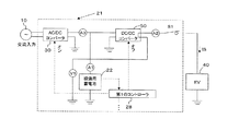
図1に、設備用蓄電池22を内蔵したEV用急速充電器(単にEV充電器とも称する)20の標準的な構成と、コンビニエンスストア(以下、コンビニとも称する)等を想定した場合の、電子レンジ等を含む店舗内の負荷設備(以下、店舗内負荷設備)14の接続状況のモデルを示す。
1 shows a standard configuration of an EV quick charger (also simply referred to as an EV charger) 20 having a built-in
交流の系統10からの入力に対して、受配電盤12を経由して、店舗内負荷設備14及びEV充電器20が接続されている。
An in-
EV40が接続されていない状態において、設備用蓄電池22に十分な電気量が蓄積されていない場合は、コントローラ28の指示によりAC/DCコンバータ24から設備用蓄電池22への補充電が行われる。設備用蓄電池22に十分な電気量が蓄積されれば該設備用蓄電池22への充電を終了する。EV40が接続されたことをコントローラ28が検出すると、コントローラ28はDC/DCコンバータ26を動作させ、EV40が要求する電流あるいは電圧値に合うよう、設備用蓄電池22の電力をDC/DCコンバータ26で変圧し、EV40への充電を行う。
In the state where the EV 40 is not connected, when a sufficient amount of electricity is not stored in the
従来の一般的な動作においては、店舗内負荷設備14とEV充電器20は、おのおの独立に必要に応じて動作しており、これらが消費する合計の電力が受電量となる。
In the conventional general operation, the in-
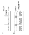
次に、EV充電器を設置していない場合の上記コンビニ店舗等における典型的な電力消費の時間変化の例を図2(a)に、従来型の設備用蓄電池内蔵型のEV充電器20を設置した場合の例を図2(b)に示す。ここでは、EV充電器20は設備用蓄電池22を内蔵しており、EV40への充電実施の有無にかかわらず、常に一定の電力消費を行っていると仮定した。実際にはEV充電器20の消費電力は一定ではなく、EV40への充電、内蔵の設備用蓄電池22への充電等の繰り返しにより絶えず変動しており、店舗等の合計の電力消費の時間変化は、図2(b)よりも更に大きなものとなっていることが想定される。
Next, an example of a time change of typical power consumption in the above convenience store or the like when no EV charger is installed is shown in FIG. An example of installation is shown in FIG. Here, it is assumed that the
図2に示すように、店舗等において通常の電力消費は、照明、エアコン等定常的な負荷が中心であるが、大出力の電子レンジ等を使用する期間(短時間)のみ消費電力量が急増している。通常の契約では、この最大電力を賄える電力で契約を行うため、平均的な電力消費に比べて高額な契約が必要となっている。この短期間的な電力消費を抑えることができれば契約金額を低減することができるばかりでなく、電力系統側にとっても、負荷の急変による周波数変動等の不安定要因を除くことができるので系統の安定性という面からも効果がある。 As shown in FIG. 2, the normal power consumption in stores and the like is centered on steady loads such as lighting and air conditioners, but the power consumption increases rapidly only during the period (short time) when a high-power microwave oven is used. is doing. In a normal contract, since the contract is made with power that can cover this maximum power, a contract that is higher than the average power consumption is required. If this short-term power consumption can be suppressed, not only can the contract amount be reduced, but the power system can also eliminate unstable factors such as frequency fluctuations due to sudden changes in the load, thus stabilizing the system. It is also effective in terms of sex.
次に、本発明に用いるEV充電器21を店舗等に設置した場合の構成例を図3に示す。図3においては、図1に対して第2のコントローラ36、電力計P1、P2が追加されている。P1はEV充電器21を除いた店舗等の消費電力を計測する電力計であり、P2はEV充電器21の消費電力を計測する電力計である。また、第2のコントローラ36は、電力計P1、P2の計測結果を受け、EV充電器21の既設コントローラ(第1のコントローラと称する)28に対してEV充電器21の制御方法を指示する制御装置である。また、図のAC/DCコンバータ30は、第1のコントローラ28からの指示に基づいて交流入力10からの使用電力を変更する機能を有するものとなっている。
Next, the structural example at the time of installing the
ここで、外部からの指示に基づいて交流電源10からの入力電力を制御することが可能なAC/DCコンバータ30の構成例と動作を図4を用いて説明する。
Here, a configuration example and operation of the AC /
図のように、交流入力10に対して絶縁トランス32を通して、入出力の絶縁とともに、必要に応じて電圧の変換を行う。その後、例えばIGBT等のスイッチング素子33により交流を直流に変換すると同時に出力電力を制御することにより、本コンバータ30への入力電力値を目標値とする電力一定制御を行う。入力電力の制御は、図に示すゲート点弧制御回路34により、各スイッチング素子33のゲート回路の通電状況を制御することにより行う。図において、35は、出力波形を整流するための、例えばコンデンサ等でなるフィルタ回路である。なお、図では入力交流として3相交流を例として示したが、単相交流でも構わない。
As shown in the figure, the
次に、図3を用いて本装置の動作を説明する。 Next, the operation of this apparatus will be described with reference to FIG.
第2のコントローラ36には、あらかじめ当該店舗の契約電力もしくは許容される最大電力P0がデータとして記憶されている。P0は本装置設置時にあらかじめ入力するが、電力負荷設備、契約電力の変更時には手動にて設定変更を行うことも可能である。
In the
P1はEV充電器21を除く店舗内使用電流の計測結果であるから、第2のコントローラ36において、P0とP1の差すなわち、
P0−P1=PR …(1)
を計算することにより、現在店舗で使用している電力と契約電力の差に相当する余剰電力値PRを計算することができる。
Since P1 is a measurement result of in-store use current excluding the
P0−P1 = PR (1)
By calculating, the surplus power value PR corresponding to the difference between the power currently used in the store and the contract power can be calculated.
続いて第2のコントローラ36は、第1のコントローラ28に対して、EV40が使用できる電力値としてPRを伝達する。
Subsequently, the
以下、第2のコントローラ36に組み込む制御プログラムのフローチャートについて、図5を用いて説明する。
Hereinafter, a flowchart of a control program incorporated in the
まず、第2のコントローラ36は、(1)式に示したように、店舗の許容電力P0と、EV充電器21以外の他の負荷設備で使用している電力P1との差を計算することにより店舗の余剰電力量PRを計算する(図5中ステップ1、以下ステップ番号において図5は省略)。
First, as shown in the equation (1), the
続いて、設備用蓄電池22の残電気量を端子電圧の計測等の方法により計測し、この残電気量がEV40の充電を行うに十分であるかどうかを判定する(ステップ2)。残電気量がEV充電を行うに十分であるかどうかの判定値は、あらかじめデータとして第2のコントローラ36に入力しておく。
Subsequently, the remaining electricity amount of the
最初にステップ2においてEV40の充電に十分な電気量がある場合の手順を説明する。
First, the procedure when there is a sufficient amount of electricity for charging the
EV40が接続され、EV40への充電が要求されているかを、CAN通信等の方法により確認する(ステップ3)。
It is confirmed by a method such as CAN communication whether the
充電要求が無い場合は、図5中丸囲み数値1へ戻る(ステップ4)。
If there is no charge request, the process returns to the circled
この場合、ステップ1→ステップ2→ステップ3→ステップ4のルートを継続することにより、本装置21は待機状態となる。
In this case, by continuing the route of
次にステップ3においてEV40が接続され、充電が要求された場合を説明する。
Next, the case where the
この場合は、ステップ3からステップ5に進む。 In this case, the process proceeds from step 3 to step 5.
ステップ5で、第2のコントローラ36は、現在の余剰電力量PRが0であるかどうかを判定する。PRが0である場合は店舗側に余剰電力が全く無い状態であるため、EV40への充電に交流入力を利用することができない。このため、EV40への充電は本装置21に内蔵された設備用蓄電池22のみを用いて行うことが必要である。そこで、第2のコントローラ36は、第1のコントローラ28を経由して、AC/DCコンバータ30の動作を停止させ、設備用蓄電池22のみでEV40への充電を行うよう、指示を行う(ステップ6)。この場合、ステップ1→ステップ2→ステップ3→ステップ5→ステップ6のルートを継続し、同じ状態が継続する限り、設備用蓄電池22のみを用いたEV40への充電を継続する。
In step 5, the
ステップ5でPRが0で無い場合、ステップ7に進み、CAN通信等でEV40から得られる要求電流値等の情報を用いて、EV40の充電に必要な電力PNを計算する。
続いて、PRとPNの大小を比較する(ステップ8)。
If PR is not 0 in step 5, the process proceeds to step 7 and the electric power PN required for charging the
Subsequently, the magnitudes of PR and PN are compared (step 8).
ステップ8において、PRの方が大きいか等しい場合、EV40から要求される電力を店舗余剰電力で十分賄えることを意味しているため、第2のコントローラ36は、第1のコントローラ28を経由して、AC/DCコンバータ30に対して入力電力PNにてEV40に充電するよう指示する(ステップ9)。この場合、EV40への充電はAC/DCコンバータ30のみの電力で行われる。同じ状態が継続する限り、ステップ1→ステップ2→ステップ3→ステップ5→ステップ7→ステップ8→ステップ9→ステップ1のルートを維持し、AC/DCコンバータ30のみを用いたEV40への充電を継続する。
In step 8, if the PR is larger or equal, it means that the power required from the
ここで、ステップ8において、PRよりもPNの方が大きい状態が発生した場合、店舗の余剰電力のみではEV40への充電に不足であることを意味するため、AC/DCコンバータ30に対しては入力電力をPRとして動作するとともに、設備用蓄電池22の電力を併用して合計電力がPNとなるように、第2のコントローラ36は第1のコントローラ28を経由してDC/DCコンバータ26を制御してEV40への充電を行う(ステップ10)。この場合の制御はステップ1→ステップ2→ステップ3→ステップ5→ステップ7→ステップ8→ステップ10→ステップ1となる。
Here, in the case where the state where the PN is larger than the PR occurs in Step 8, it means that the surplus power of the store alone is insufficient for charging the
以上、設備用蓄電池22が十分な残電力量を保有している場合の制御手順を説明した。
The control procedure in the case where the
次に設備用蓄電池22の残電力量が少なく、EV40への充電ができない場合の制御手順を説明する。
Next, a description will be given of a control procedure in a case where the amount of remaining power of the
図5のステップ2よりステップ11に進み、ステップ3と同様にEV40からの充電要求があるかどうかを判定する。
The process proceeds from step 2 in FIG. 5 to step 11 to determine whether there is a charge request from the
最初にEV40が接続されていない場合を説明する。この場合はAC/DCコンバータ30の入力をPRとして設備用蓄電池22への充電を行う(ステップ12)。ただし、設備用蓄電池22への充電は、定電圧定電流法等、設備用蓄電池の特性に合わせた方法で実施する必要があるため、店舗の余剰電力PRを最大値として第1のコントローラ28により充電を行う。この状態が継続すれば、ステップ1→ステップ2→ステップ11→ステップ12→ステップ1のルートを維持して設備用蓄電池22への充電を継続する。設備用蓄電池22に十分な電力量が蓄積されれば、前記のとおりステップ2からステップ3へ進む。
First, the case where the
一方、ステップ11においてEV40が接続されたことを検出した場合、設備用蓄電池22を使用せず、AC/DCコンバータ30を経由してEV40への充電を行う必要があるため、ステップ13において設備用蓄電池22とAC/DCコンバータ30間に設けられた常時閉であるスイッチ(図3には図示せず)を開放し、設備用蓄電池22を切り離す。この理由は、AC/DCコンバータ30の出力に容量が少ない設備用蓄電池22が接続された状態では、DC/DCコンバータ26を経由してEV40への充電を行うと同時に設備用蓄電池22への補充電が行われてしまい、EV40への充電の効率が低下するからである。
On the other hand, if it is detected in step 11 that the
続いてステップ14において、ステップ5と同様PRが0であるかどうかを判定する。PRが0でなければPRの数値から、EV40への充電に利用できる電流値を計算し、CAN通信等を通じてEV40に情報を提供する(ステップ15)。この理由は、現在のEV接続の標準的なプロトコルにおいては、CAN通信を経由して予めEV充電器20が充電に利用可能な電流値をEV40に通知することになっているためである。もし他のプロトコルを利用する場合は、そのプロトコルの規定に従って充電電流を決定することも可能である。続いてステップ16において、AC/DCコンバータ30への入力電力がPRとなるよう、第2のコントローラ36は第1のコントローラ28を経由して制御を行い、EV40への充電を行う。この場合、ステップ1→ステップ2→ステップ11→ステップ13→ステップ14→ステップ15→ステップ16→ステップ1を継続する。
Subsequently, in
最後にステップ14においてPRが0であった場合、設備用蓄電池22の残容量が不足し、かつ店舗の余剰電力も無い状態であるため、この時点ではEV40への充電は行えないため、店舗の余剰電力が発生するまで待機する必要がある(ステップ17)。ただし、図2にも示したとおり、店舗でのピーク電力の発生は例えば1分等、きわめて短時間であり、この間を待機することは大きな問題ではない。この場合、ステップ1→ステップ2→ステップ11→ステップ13→ステップ14→ステップ17→ステップ1を継続する。
Finally, if PR is 0 in
このような状況でも待機することなく常にEV充電を実施したい場合には、店舗側での余剰電力の発生状況と、EV40への充電頻度を考慮の上設備用蓄電池の容量を適切に設定する方法がある他、図6に示す第2実施形態のように、設備用蓄電池22を2組以上(図では22A、22Bの2組)搭載し、スイッチSW1〜5を適宜切換えて、設備用蓄電池22への補充電とEV40への充電とを交互に行う等の方法も可能である。
In such a situation, when it is desired to always carry out EV charging without waiting, a method of appropriately setting the capacity of the storage battery for facilities in consideration of the generation of surplus power at the store and the frequency of charging to the
以上の制御プログラムを第2のコントローラ36に搭載することにより、EV充電器21は常に使用電力が余剰電力PR以下となるように動作を行う。この結果、EV充電器21を含む店舗での合計の使用電流は、常に契約電力P0以下とすることができる。
By mounting the above control program on the
この状況を店舗の消費電力の時間推移の例として図7に示す。 This situation is shown in FIG. 7 as an example of the time transition of the power consumption of the store.
以上説明した本装置により、EV充電器21を設置した店舗等での契約電力を増加させることなく、店舗側での余剰電力のみを利用することによりEV40への急速充電に必要な電力を賄うことができる。
With this device described above, the power required for rapid charging to the
なお、本装置で説明したEV充電器は、設備用蓄電池22を内蔵したEV充電器の基本的な構成には設計変更を加えることなく負荷平準化が可能である。
Note that the EV charger described in the present apparatus can be load leveled without changing the design of the basic configuration of the EV charger including the
尚、第2実施形態では、設備用蓄電池22が2組設けられていたが、3組以上であっても良い。
In addition, in 2nd Embodiment, although the two sets of
ここで、DC/DCコンバータ26は通常、変換効率ηが最大でも95%程度である。また、設備用蓄電池22に一旦蓄電することによるエネルギーロスは、蓄電池の種類にもよるが、効率の高いものを用いることにより98%程度となる。
Here, the DC /
従って、図3に示す方式では、入力交流電力と、負荷を充電するための電力との比である総合効率η20は、DC/DCコンバータ26の一次側に入力される電力が設備用蓄電池22のみから供給される場合、次式で示され、約88.4%となる。
η20=0.95×0.98×0.95=0.884 …(2)
Therefore, in the method shown in FIG. 3, the total efficiency η20, which is the ratio of the input AC power and the power for charging the load, is the power input to the primary side of the DC /
η20 = 0.95 × 0.98 × 0.95 = 0.848 (2)
すなわち、交流入力から得た電力のうち、(100−88.4=)11.6%が熱となって消費されてしまう。この総合効率が低いことが問題となることがある。 That is, (100-88.4 =) 11.6% of the electric power obtained from the AC input is consumed as heat. This low overall efficiency can be problematic.
また、DC/DCコンバータ26の容量は、当然ながら負荷を充電する際に必要となる電力を供給できるだけの容量を保有することが必要である。例えば、負荷となるEV40への出力電力が100kWであるとすると、DC/DCコンバータ26への入力電力は105.3kW、設備用蓄電池22の充放電ロスを考慮して設備用蓄電池22への入力は107.4kWとなる。従って、AC/DCコンバータ30への入力電力は113.1kWが必要である。よって、上記数値例では、AC/DCコンバータ30で113.1kW、DC/DCコンバータ26で100kWの電力容量が必要となる。
Further, the capacity of the DC /
そこで、本発明の第3実施形態では、図8に示す如く、絶縁型とされたDC/DCコンバータ50の二次側の接地側配線51をアースではなく、設備用蓄電池22に接続している。このDC/DCコンバータ50は、絶縁型、すなわち、入力側と出力側の接地端子が絶縁されているものを用いる。その他の構成は図3と同じである。
Therefore, in the third embodiment of the present invention, as shown in FIG. 8, the secondary-side ground-
絶縁型のDC/DCコンバータ50の回路例を図9に示す。図9では、絶縁トランス50Aの一次側に直流電源を接続し、ゲート制御されるトランジスタ50Bによるスイッチで電流のオンオフを行う。絶縁トランス50Aの二次側には誘導起電力が発生し、ダイオード50Cとキャパシタ50Dにより整流されて出力される。出力電圧をセンサー50Eにより検出して、トランジスタ50Bの駆動波形を制御することにより、出力電圧を所望の電圧に制御する。絶縁トランス50Aを用いることにより、DC入力とDC出力のグランドレベルを変更可能であることから、絶縁型と呼ばれている。図9に示したのは絶縁型DC/DCコンバータの一例であり、絶縁型であれば他の方式でも構わない。
A circuit example of the insulation type DC /
以下、第3実施形態の制御方法を説明する。 Hereinafter, the control method of the third embodiment will be described.
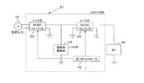
図10に、第2のコントローラ36等の記載を省略した、制御系統も含む第3実施形態の要部の構成を示す。図10において、AC/DCコンバータ30、絶縁型DC/DCコンバータ50、スイッチS1等の制御は、例えば第1のコントローラ28により行う。V1は、設備用蓄電池22の電圧をモニタして残量を把握するための電圧計である。
FIG. 10 shows the configuration of the main part of the third embodiment including the control system, omitting the description of the
(1)EV40が接続されていない場合
この場合、図11に示す如く、DC/DCコンバータ50の動作を停止し、AC/DCコンバータ30により設備用蓄電池22を充電する。充電方法は、例えばフローティング充電を行うことができる。EV40が接続されていないことは、例えばユーザーインタフェース装置(図示省略)からEV40が接続されていることを示す信号が出ないことで検出する。あるいは、図12に示す如く、車載用LAN(Local Area Network)であるCAN(Controller Area Network)を利用したEV40側とのCAN通信等により検出できる。
(1) When
(2)EV40が接続された場合
CAN通信等によりEV40が接続されたことを検出すると、図13に示す如く、スイッチS1を閉じることにより充電動作を開始する。充電電流はCAN通信等によりEV40側から指示がある場合は、その電流値ISになるよう、DC/DCコンバータ20を制御する。EV40側から充電電流の指示がない場合は、例えばDC/DCコンバータ50の出力側で充電電流A2を計測した結果に基づき、適切な電流値に設定する。適切な電流値は、外部入力等により設定することができる。
(2) When
DC/DCコンバータ50は、出力側の充電電流A2がISと等しくなる様、出力電圧を制御する。本構成によれば、EV40とDC/DCコンバータ50が直列に接続されており、DC/DCコンバータ50の出力電圧は、設備用蓄電池22の電圧により常に変化させる必要があるため、ISとA2の比較処理は、ある一定周期で実施する。
The DC /
次に、DC/DCコンバータ50の一次側に加える電力を、AC/DCコンバータ30の出力電圧を変化させることにより制御する。ここで、(a)設備用蓄電池22の持つ電力を優先的に使用し、交流入力10からのAC電力使用量を極力少なくする場合、(b)交流入力10からのAC電力を優先的に使用し、設備用蓄電池22の電力を極力少なくする場合、(c)設備用蓄電池22を使用せず、AC/DCコンバータ30の出力のみを利用して本装置を動作させる場合の3通りがある。これらはユーザーインタフェースにより選択することも可能であるし、あらかじめ設定することも可能である。
Next, the power applied to the primary side of the DC /
例えば、本装置の利用が昼間に限られ、夜間電力による充電を優先して、昼間は交流入力を極力削減したいという場合に、朝の時間帯は上記(a)を使用してAC入力からの電力消費を低減し、設備用蓄電池22の残量が減少した後は上記(b)を使用することにより設備用蓄電池22の残量を確保しつつ急速充電を可能とするという使い方が考えられる。通常は(a)もしくは(b)の動作を用いるが、設備用蓄電池22の残量が極端に少なくなり、設備用蓄電池22からEV40への充電が実施できない場合には(c)の動作を行うことができる。
For example, when the use of this device is limited in the daytime and priority is given to charging with nighttime power and it is desired to reduce the AC input as much as possible during the daytime, the morning time zone can be After the power consumption is reduced and the remaining amount of the
上記(a)の場合、第1のコントローラ28は、AC/DCコンバータ30の出力電流A3が十分小さく、設備用蓄電池22からの出力電流A1が大きくなるよう、AC/DCコンバータ30の出力電圧を低く設定するような制御を行う。
In the case of (a), the
上記(b)の場合、第1のコントローラ28は、(a)と逆に、AC/DCコンバータ30の出力電流A3が十分大きく、設備用蓄電池22からの出力電流A1が小さくなるよう、AC/DCコンバータ30の出力電圧を高く設定するような制御を行う。
In the case of the above (b), the
上記(c)の場合、第1のコントローラ28は、図14に示すように、DC/DCコンバータ50の動作を停止させ、該DC/DCコンバータ50に内蔵されたスイッチ(図示省略)により該DC/DCコンバータ50の二次側接続を短絡させることにより、AC/DCコンバータ30からの電力が、該DC/DCコンバータ50をバイパスして、直接、EV40の充電に用いられるよう、制御を行う。この場合は設備用蓄電池22による電力が利用できないため、充電速度はAC/DCコンバータ30の容量により制限される低い速度となるものの、EV40の充電は継続できる。
In the case of (c), the
上記(a)の動作を行っている途中で設備用蓄電池22の残容量が減少した場合、設備用蓄電池22の残量を残しつつEV40の充電を継続して行うために、上記(b)の動作に自動的に切り換える動作を行うよう第1のコントローラ28をプログラムすることも可能である。
When the remaining capacity of the
あるいは、設備用蓄電池22の残量に応じて、(a)の動作で充電が完了できないことを予測した場合は、あらかじめ(b)の動作を行うように第1のコントローラ28のプログラムを設定することも可能である。
Alternatively, when it is predicted that charging cannot be completed by the operation (a) according to the remaining amount of the
これらの動作を行うため、第1のコントローラ28は設備用蓄電池22の残量を一定周期で把握する機能を有する必要がある。
In order to perform these operations, the
なお、第1のコントローラ28とユーザーインタフェース装置との通信は、第1のコントローラ28に本機能を含めることも可能であるが、あるいは専用の通信機能を有するモジュールを搭載しても良い。
The communication between the
次に、第3実施形態による総合効率の向上効果について検討する。 Next, the effect of improving the overall efficiency according to the third embodiment will be examined.
図8の回路では、設備用蓄電池22からの出力電力は、2つの経路に分かれる。一つはDC/DCコンバータ50の一次側に接続され、他方は配線51によりDC/DCコンバータ50の二次側に直列に接続される。この場合、DC/DCコンバータ50の二次側に設備用蓄電池22が直列に接続されて電圧がかさ上げされているため、DC/DCコンバータ50の出力電圧は図15に示す従来例の場合に比べて小さくて済む。これにより、DC/DCコンバータ50が扱う電力は図15に比べて小さくできる。
In the circuit of FIG. 8, the output power from the
通常のDC/DCコンバータ26と本実施形態に係るDC/DCコンバータ50の効率が同じとすると、DC/DCコンバータを通る電力に比例した電力損失が発生するため、図15の場合に比べDC/DCコンバータでの電力ロスが少なくなり、結果的に総合効率ηが向上する。
If the efficiency of the normal DC /
上記と同様の計算例を以下に示す。 A calculation example similar to the above is shown below.
図8の回路構成においては、設備用蓄電池22の出力の一部がDC/DCコンバータ50の一次側に、残りが二次側に供給されることになり、その分担割合は、設備用蓄電池22の残量と、EV40の残量により連続的に変化する。
In the circuit configuration of FIG. 8, a part of the output of the
最も極端な例として、DC/DCコンバータ50の一次側の流入電力がAC/DCコンバータ30のみから供給される場合(これは、例えばAC/DCコンバータ30の出力電圧を設備用蓄電池22の電圧に比べて十分高くすることにより実現できる)と、逆にDC/DCコンバータ50の一次側の流入電力が設備用蓄電池22のみから供給される場合(上記と逆に設備用蓄電池22の電圧に比べてAC/DCコンバータ30の出力電圧を十分低くすることにより実現できる)が考えられる。それぞれの場合の等価的な回路図を図16、図17に示す。
As the most extreme example, when the inflow power on the primary side of the DC /
以下に、図16、図17におけるシステムの総合効率η30、η40を計算する。前提条件は上述と同じとする。 In the following, the overall efficiencies η30 and η40 of the systems in FIGS. 16 and 17 are calculated. The preconditions are the same as described above.
まず最初に仮定として、設備用蓄電池22の電圧は、負荷となるEV40の電圧の1/2、すなわち、DC/DCコンバータ50の出力電圧と設備用蓄電池22の電圧が等しい場合を考える。
First, it is assumed that the voltage of the
図16の場合では、DC/DCコンバータ50の出力の効率は、AC/DCコンバータ30の出力に直接接続されているため、
0.95×0.95=0.9025である。
In the case of FIG. 16, the efficiency of the output of the DC /
0.95 × 0.95 = 0.9025.
設備用蓄電池22の出力の効率は0.95×0.98=0.931である。
The output efficiency of the
これらを直列に接続した場合のEV40への総合効率η30は、これらの電圧が等しいことから、次式のようになる。
η30=0.9025×0.5+0.931×0.5=0.917 …(3)
When these are connected in series, the total efficiency η30 to the
η30 = 0.09025 × 0.5 + 0.931 × 0.5 = 0.997 (3)
一方、図17の場合を同様に計算する。DC/DCコンバータ50の二次側出力は設備用蓄電池22より供給されるので、その効率は
0.931×0.95=0.8845である。
On the other hand, the case of FIG. 17 is similarly calculated. Since the secondary side output of the DC /
DC/DCコンバータ50の二次側に直列接続された設備用蓄電池22の効率は0.931であるから、総合効率η40は、次式のようになる。
η40=0.8845×0.5+0.931×0.5=0.9078 …(4)
Since the efficiency of the
η40 = 0.8845 × 0.5 + 0.931 × 0.5 = 0.09078 (4)
すなわち、図16、図17のいずれの場合でも、前出(2)式で計算した図15の場合の総合効率η20=0.884を上回ることがわかる。また実際の動作は、図16と図17の中間の状態となり、その効率はη30とη40の間の数値となるため、いずれの場合であっても図15よりも効率が高いことが示される。 That is, in either case of FIG. 16 or FIG. 17, it can be seen that the total efficiency η20 = 0.848 in the case of FIG. 15 calculated by the above equation (2) is exceeded. Further, the actual operation is in an intermediate state between FIG. 16 and FIG. 17, and the efficiency is a numerical value between η30 and η40, which indicates that the efficiency is higher than that in FIG. 15 in any case.
上述の例では、設備用蓄電池22の電圧は、負荷となるEV40の電圧の1/2と仮定したが、設備用蓄電池22の電圧が小さくなるほど、DC/DCコンバータ50の分担が増すためにシステム全体としての効率が低下する。
In the above-described example, the voltage of the
以下では、EV40の電圧に対する設備用蓄電池22の電圧の比率をPとして、総合効率ηを計算する。この場合、図17より、DC/DCコンバータ50の出力電圧は(1−P)と表される。
In the following, the overall efficiency η is calculated with the ratio of the voltage of the
図16の回路構成の場合の総合効率η31は、次式のようになる。
η31=0.95×0.95×(1−P)+(0.95×0.98)×P …(5)
The total efficiency η31 in the case of the circuit configuration of FIG.
η31 = 0.95 × 0.95 × (1-P) + (0.95 × 0.98) × P (5)
同じく図17の場合の総合効率η41は、次式のようになる。
η41=0.95×0.98×0.95×(1−P)+(0.95×0.98)×P
…(6)
Similarly, the total efficiency η41 in the case of FIG.
η41 = 0.95 × 0.98 × 0.95 × (1-P) + (0.95 × 0.98) × P
(6)
システム全体の総合効率η11は、設備用蓄電池22とEV40の残量により、η31とη41の間の数値となる。
The overall efficiency η11 of the entire system is a numerical value between η31 and η41 depending on the remaining capacity of the storage battery for
ここで、η11の最小値を求める。η31とη41を比較すると必ずη31>η41となるので、最小値はη41である。 Here, the minimum value of η11 is obtained. When η31 and η41 are compared, η31> η41 is always satisfied, and therefore the minimum value is η41.
また、η41の(6)式より、η41は、Pが0に近いほど小さくなる。その最小値はP=0の場合であるが、この場合は設備用蓄電池22の電圧が0となり、装置が動作しないため、ほぼ0に近い場合がこれに相当すると考えられる。
Further, from equation (6) of η41, η41 becomes smaller as P is closer to 0. The minimum value is when P = 0. In this case, the voltage of the
Pがほぼ0と仮定すると、このときの総合効率ηMINは、次式で示される。
ηMIN=0.95×0.98×0.95 …(7)
Assuming that P is approximately 0, the total efficiency ηMIN at this time is expressed by the following equation.
ηMIN = 0.95 × 0.98 × 0.95 (7)
これは図15の場合の総合効率η20に等しい。 This is equal to the overall efficiency η20 in the case of FIG.
すなわち、図8の構成をとることにより、設備用蓄電池22の電圧が0より大きければ、必ず図15の構成に比べてシステム全体の効率は高くなる。
That is, by taking the configuration of FIG. 8, if the voltage of the
一方、DC/DCコンバータ50の容量は、図8の構成をとることにより、図15に比べて小さなもので済むことが示される。例えば、設備用蓄電池22の電圧が、負荷となるEV40電圧の1/2である上述の例では、出力100kWに対して、DC/DCコンバータ50の容量は、1/2の50kWとなる。このことは、設備コスト、重量等の削減に効果的である。
On the other hand, it is shown that the capacity of the DC /
次に、図8の構成において、設備用蓄電池22の電圧設定に関する条件を示す。
Next, in the configuration of FIG. 8, conditions relating to voltage setting of the
設備用蓄電池22、EV40ともに電圧は、電池残量により変動する。
The voltage of both the
設備用蓄電池22の最大、最小電圧をそれぞれVBMax、VBMin、EV40の最大、最小電圧をそれぞれVEMax、VEMinとすると、設備用蓄電池22の電圧は以下のように設定される。
When the maximum and minimum voltages of the
DC/DCコンバータ50の出力電圧は負にはできないため、
VBMax≦VEMin
である。すなわち、設備用蓄電池22の電圧VBがいかなる値であっても、EV40の電圧VEを上回らないことが条件となる。
Since the output voltage of the DC /
VBMax ≦ VEMin
It is. That is, it is a condition that the voltage VB of the
また、設備用蓄電池22の電圧VBが小さいほど、DC/DCコンバータ50による昇圧が必要であり、効率低下を招くので、設備用蓄電池22の電圧VBは、できるだけEV40の電圧VEに近いことが望ましい。
Further, as the voltage VB of the
以上の検討より、VBMax=VEMinとなる電圧設定が最も効率的である。 From the above examination, voltage setting such that VBMax = VEMin is the most efficient.
ただし、実際の電池選定に当たっては、全体コスト、電池の入手性等を考慮する必要があることから、VBMax=VEMinに限定されることはない。上述の検討結果が示すように、図8の回路構成をとる限り、設備用蓄電池22の電圧VBが0でなければ必ず効率は向上するので、電池電圧の設定は任意となる。
However, in actual battery selection, it is necessary to consider the overall cost, battery availability, and the like, and therefore, it is not limited to VBMax = VEMin. As shown in the above examination results, as long as the circuit configuration of FIG. 8 is adopted, the efficiency is always improved unless the voltage VB of the
なお、前記の各蓄電池、AC/DCコンバータ、DC/DCコンバータの出力容量は一例であり、装置の負荷となる外部蓄電池の容量、装置に要求される稼働率などを考慮の上、最適な数値を選定することが可能である。 The output capacity of each of the above storage batteries, AC / DC converter, and DC / DC converter is an example, and the optimum numerical value is taken into consideration in consideration of the capacity of the external storage battery that is the load of the apparatus, the operating rate required for the apparatus, etc. Can be selected.
又、使用態様によっては、AC/DCコンバータ30を外付けとして、EV充電器21から省略することも可能である。
Further, depending on the usage mode, the AC /
以上説明した内容について、本装置を設置する施設等については、コンビニエンスストアを例に説明したが、これに限らず、ガソリンスタンド、駐車場、工場、一般企業等、同種の負荷パターンを持つあらゆる店舗、電力需要家等の電力消費施設に適用可能である。 About the contents explained above, the facilities where this device is installed were explained using convenience stores as an example, but not limited to this, any store with the same type of load pattern such as gas stations, parking lots, factories, general companies, etc. It can be applied to power consuming facilities such as power consumers.
また、各実施形態においてEV充電器21内の第1のコントローラ28と独立に第2のコントローラ36を設けることとしたが、2台のコントローラを集約して1台のコントローラに置き換えても良く、さらにAC/DCコンバータ30あるいはDC/DCコンバータ26の制御回路に同機能を保有させてもかまわない。
In each embodiment, the
また、前記実施形態においては、本発明がEVへの急速充電器に適用されていたが、本発明の急速充電対象はこれに限定されない。 Moreover, in the said embodiment, although this invention was applied to the quick charger to EV, the quick charge object of this invention is not limited to this.
10…交流入力
12…受配電盤
14…店舗(電力消費施設)内負荷設備
21…電気自動車用急速充電器(EV充電器)
22…設備用蓄電池
26、50…DC/DCコンバータ
28、36…コントローラ
30…AC/DCコンバータ
40…電気自動車(EV)
P1、P2…電力計
10 ...
22 ... Storage battery for
P1, P2 ... Wattmeter
Claims (12)
該設備用蓄電池の出力を前記外部蓄電池への充電に適した電流や電圧に変換するDC/DCコンバータと、
外部からの交流入力を用いて前記設備用蓄電池を充電するための、外部からの入力電力を制御することが可能なAC/DCコンバータと、
これらを制御するコントローラと、
を備えたことを特徴とする急速充電器。 A storage battery for facilities capable of charging an external storage battery;
A DC / DC converter for converting the output of the facility storage battery into a current or voltage suitable for charging the external storage battery;
An AC / DC converter capable of controlling input power from the outside for charging the storage battery for equipment using an AC input from outside;
A controller to control these,
A quick charger characterized by comprising:
交流側と入力側の絶縁及び必要に応じて電圧の変更を行うための絶縁トランスと、
交流から直流への変換を行うためのスイッチング素子と、
該スイッチング素子により生成された、前記設備用蓄電池を充電する直流出力を平滑化するためのフィルタ回路と、
前記スイッチング素子を制御して、該AC/DCコンバータへの入力電力を目標値に制御する制御回路と、
を備えたことを特徴とする請求項1に記載の急速充電器。 The AC / DC converter is
Insulation transformer for insulation between AC side and input side and voltage change as necessary,
A switching element for performing conversion from alternating current to direct current,
A filter circuit for smoothing a DC output generated by the switching element and charging the storage battery for equipment;
A control circuit for controlling the switching element to control the input power to the AC / DC converter to a target value;
The quick charger according to claim 1, further comprising:
該急速充電器が設置された電力消費施設の急速充電器以外の設備による消費電力を測定する手段と、
前記急速充電器による消費電力を測定する手段と、を備え、
前記電力消費施設の急速充電器以外の設備による消費電力と契約電力との差分である余剰電力のみを、前記急速充電器で消費するようにしたことを特徴とする急速充電装置。 A quick charger according to any one of claims 1 to 4,
Means for measuring power consumption by equipment other than the quick charger of the power consumption facility where the quick charger is installed;
Means for measuring power consumption by the quick charger,
A rapid charging apparatus characterized in that only the surplus power that is the difference between the power consumed by equipment other than the rapid charger at the power consuming facility and the contract power is consumed by the rapid charger.
前記急速充電器が設置された電力消費施設の急速充電器以外の設備による消費電力と契約電力との差分である余剰電力のみを、前記急速充電器で消費することを特徴とする急速充電方法。 In the power consumption facility in which the quick charger according to any one of claims 1 to 4 is installed,
A rapid charging method characterized in that only the surplus power that is the difference between the power consumed by equipment other than the rapid charger in the power consumption facility where the quick charger is installed and the contract power is consumed by the rapid charger.
前記余剰電力のみで外部蓄電池を充電することを特徴とする請求項7に記載の急速充電方法。 If the amount of remaining electricity of the storage battery for facilities is not sufficient for charging to the external storage battery, do not use the storage battery for facilities to charge to the external storage battery,
The rapid charging method according to claim 7, wherein the external storage battery is charged only with the surplus power.
Priority Applications (1)
| Application Number | Priority Date | Filing Date | Title |
|---|---|---|---|
| JP2011125813A JP2012253952A (en) | 2011-06-03 | 2011-06-03 | Fast charger, fast charging apparatus and fast charging method |
Applications Claiming Priority (1)
| Application Number | Priority Date | Filing Date | Title |
|---|---|---|---|
| JP2011125813A JP2012253952A (en) | 2011-06-03 | 2011-06-03 | Fast charger, fast charging apparatus and fast charging method |
Publications (1)
| Publication Number | Publication Date |
|---|---|
| JP2012253952A true JP2012253952A (en) | 2012-12-20 |
Family
ID=47526196
Family Applications (1)
| Application Number | Title | Priority Date | Filing Date |
|---|---|---|---|
| JP2011125813A Pending JP2012253952A (en) | 2011-06-03 | 2011-06-03 | Fast charger, fast charging apparatus and fast charging method |
Country Status (1)
| Country | Link |
|---|---|
| JP (1) | JP2012253952A (en) |
Cited By (10)
| Publication number | Priority date | Publication date | Assignee | Title |
|---|---|---|---|---|
| JP2014138534A (en) * | 2013-01-18 | 2014-07-28 | Kyocera Corp | Power control unit, power control system, and power control method |
| CN105720655A (en) * | 2016-04-15 | 2016-06-29 | 力帆实业(集团)股份有限公司 | Electric automobile, DC/DC converter and control system thereof |
| CN105720653A (en) * | 2016-04-15 | 2016-06-29 | 力帆实业(集团)股份有限公司 | Electric automobile, DC/DC converter and control system thereof |
| JP2017034840A (en) * | 2015-07-31 | 2017-02-09 | 日本電気株式会社 | Power storage system |
| JP2018014849A (en) * | 2016-07-22 | 2018-01-25 | 株式会社豊田自動織機 | Charger |
| CN112186820A (en) * | 2019-07-02 | 2021-01-05 | 台达电子工业股份有限公司 | Charger and charging method |
| JP2021048667A (en) * | 2019-09-17 | 2021-03-25 | 河村電器産業株式会社 | Vehicle charging device |
| WO2023074434A1 (en) * | 2021-10-27 | 2023-05-04 | ヤマハ発動機株式会社 | Electricity storage-type charging device, electricity storage-type charging system, and high-current chargeable driving lithium-ion battery |
| JP7388514B1 (en) | 2022-09-30 | 2023-11-29 | 株式会社村田製作所 | Commercial in-store consumption power system |
| KR102664461B1 (en) * | 2023-11-01 | 2024-05-08 | 주식회사 이온 | Charging device and system operation method for electric vehicle including battery stack |
Citations (4)
| Publication number | Priority date | Publication date | Assignee | Title |
|---|---|---|---|---|
| JPH10108381A (en) * | 1996-09-12 | 1998-04-24 | Internatl Business Mach Corp <Ibm> | Charger and electronic apparatus provided with charging function |
| JPH11136852A (en) * | 1997-10-27 | 1999-05-21 | Nippon Telegr & Teleph Corp <Ntt> | Power storage system |
| JP2008136291A (en) * | 2006-11-28 | 2008-06-12 | Nissan Motor Co Ltd | Charging power management system for motor-driven vehicle |
| WO2011021718A1 (en) * | 2009-08-21 | 2011-02-24 | Jfeエンジニアリング株式会社 | Quick charging device |
-
2011
- 2011-06-03 JP JP2011125813A patent/JP2012253952A/en active Pending
Patent Citations (4)
| Publication number | Priority date | Publication date | Assignee | Title |
|---|---|---|---|---|
| JPH10108381A (en) * | 1996-09-12 | 1998-04-24 | Internatl Business Mach Corp <Ibm> | Charger and electronic apparatus provided with charging function |
| JPH11136852A (en) * | 1997-10-27 | 1999-05-21 | Nippon Telegr & Teleph Corp <Ntt> | Power storage system |
| JP2008136291A (en) * | 2006-11-28 | 2008-06-12 | Nissan Motor Co Ltd | Charging power management system for motor-driven vehicle |
| WO2011021718A1 (en) * | 2009-08-21 | 2011-02-24 | Jfeエンジニアリング株式会社 | Quick charging device |
Cited By (13)
| Publication number | Priority date | Publication date | Assignee | Title |
|---|---|---|---|---|
| JP2014138534A (en) * | 2013-01-18 | 2014-07-28 | Kyocera Corp | Power control unit, power control system, and power control method |
| JP2017034840A (en) * | 2015-07-31 | 2017-02-09 | 日本電気株式会社 | Power storage system |
| CN105720655A (en) * | 2016-04-15 | 2016-06-29 | 力帆实业(集团)股份有限公司 | Electric automobile, DC/DC converter and control system thereof |
| CN105720653A (en) * | 2016-04-15 | 2016-06-29 | 力帆实业(集团)股份有限公司 | Electric automobile, DC/DC converter and control system thereof |
| JP2018014849A (en) * | 2016-07-22 | 2018-01-25 | 株式会社豊田自動織機 | Charger |
| JP2021010293A (en) * | 2019-07-02 | 2021-01-28 | 台達電子工業股▲ふん▼有限公司Delta Electronics,Inc. | Charger and charging method |
| CN112186820A (en) * | 2019-07-02 | 2021-01-05 | 台达电子工业股份有限公司 | Charger and charging method |
| JP2021048667A (en) * | 2019-09-17 | 2021-03-25 | 河村電器産業株式会社 | Vehicle charging device |
| JP7365829B2 (en) | 2019-09-17 | 2023-10-20 | 河村電器産業株式会社 | vehicle charging device |
| WO2023074434A1 (en) * | 2021-10-27 | 2023-05-04 | ヤマハ発動機株式会社 | Electricity storage-type charging device, electricity storage-type charging system, and high-current chargeable driving lithium-ion battery |
| WO2023073829A1 (en) * | 2021-10-27 | 2023-05-04 | ヤマハ発動機株式会社 | Storage-type charging device and charging system |
| JP7388514B1 (en) | 2022-09-30 | 2023-11-29 | 株式会社村田製作所 | Commercial in-store consumption power system |
| KR102664461B1 (en) * | 2023-11-01 | 2024-05-08 | 주식회사 이온 | Charging device and system operation method for electric vehicle including battery stack |
Similar Documents
| Publication | Publication Date | Title |
|---|---|---|
| JP2012253952A (en) | Fast charger, fast charging apparatus and fast charging method | |
| EP2683048B1 (en) | Charging power control system | |
| US9735619B2 (en) | Power conversion device | |
| JP6028499B2 (en) | Power supply | |
| US20190168632A1 (en) | Electric-vehicle energy management system, control method thereof, and electric vehicle | |
| US9906025B2 (en) | Electric power supply apparatus and system | |
| US9190915B2 (en) | Electric-power conversion device | |
| EP2587623A1 (en) | Dc power distribution system | |
| US9676287B2 (en) | Electric battery charging installation and method | |
| US11241975B2 (en) | Electric vehicle home microgrid power system | |
| JP2015106962A (en) | Charge discharge controller and charge discharge system | |
| JP5756903B2 (en) | Power distribution system | |
| JP2014023376A (en) | Power control device | |
| JP2017169313A (en) | Power storage device, apparatus, and control method | |
| JP5396549B1 (en) | Charge / feed device, charge / feed management device, energy management system, and charge / feed management method | |
| JP4098182B2 (en) | Motor drive system and elevator drive system | |
| JP2012100443A (en) | Fast charging method and device | |
| US20210370795A1 (en) | Minimum Cost Demand Charge Management by Electric Vehicles | |
| JP2012151938A (en) | Quick charger, load equalization method and quick charge method using the quick charger | |
| KR101769468B1 (en) | Control system for storing and supplying power having input and output function by switiching | |
| KR101087259B1 (en) | Power supply system and management method thereof | |
| JP6076381B2 (en) | Power supply system | |
| JP2014121216A (en) | Power storage equipment and quick charger | |
| JP2016036253A (en) | Power control device, power supply system using the same and power control method | |
| JP2015091182A (en) | Quick charge device and method |
Legal Events
| Date | Code | Title | Description |
|---|---|---|---|
| A621 | Written request for application examination |
Free format text: JAPANESE INTERMEDIATE CODE: A621 Effective date: 20130806 |
|
| A977 | Report on retrieval |
Free format text: JAPANESE INTERMEDIATE CODE: A971007 Effective date: 20140422 |
|
| A131 | Notification of reasons for refusal |
Free format text: JAPANESE INTERMEDIATE CODE: A131 Effective date: 20140513 |
|
| A02 | Decision of refusal |
Free format text: JAPANESE INTERMEDIATE CODE: A02 Effective date: 20141014 |