JP2012253531A - Imaging apparatus, imaging method, and image processing device - Google Patents
Imaging apparatus, imaging method, and image processing device Download PDFInfo
- Publication number
- JP2012253531A JP2012253531A JP2011124055A JP2011124055A JP2012253531A JP 2012253531 A JP2012253531 A JP 2012253531A JP 2011124055 A JP2011124055 A JP 2011124055A JP 2011124055 A JP2011124055 A JP 2011124055A JP 2012253531 A JP2012253531 A JP 2012253531A
- Authority
- JP
- Japan
- Prior art keywords
- image data
- image
- pixels
- similarity
- image sensor
- Prior art date
- Legal status (The legal status is an assumption and is not a legal conclusion. Google has not performed a legal analysis and makes no representation as to the accuracy of the status listed.)
- Withdrawn
Links
- 238000012545 processing Methods 0.000 title claims description 58
- 238000003384 imaging method Methods 0.000 title claims description 35
- 238000006243 chemical reaction Methods 0.000 claims description 17
- 230000033001 locomotion Effects 0.000 claims description 9
- 230000003287 optical effect Effects 0.000 claims description 6
- 238000000034 method Methods 0.000 description 17
- 230000009467 reduction Effects 0.000 description 16
- 230000008569 process Effects 0.000 description 13
- 238000012544 monitoring process Methods 0.000 description 11
- 239000003086 colorant Substances 0.000 description 7
- 238000010586 diagram Methods 0.000 description 3
- 238000011946 reduction process Methods 0.000 description 3
- 230000006872 improvement Effects 0.000 description 2
- 230000000284 resting effect Effects 0.000 description 2
- 238000012935 Averaging Methods 0.000 description 1
- 230000005540 biological transmission Effects 0.000 description 1
- 230000008859 change Effects 0.000 description 1
- 230000006866 deterioration Effects 0.000 description 1
- 230000000694 effects Effects 0.000 description 1
- 230000004048 modification Effects 0.000 description 1
- 238000012986 modification Methods 0.000 description 1
- 238000010606 normalization Methods 0.000 description 1
- 238000005070 sampling Methods 0.000 description 1
Images


Classifications
-
- H—ELECTRICITY
- H04—ELECTRIC COMMUNICATION TECHNIQUE
- H04N—PICTORIAL COMMUNICATION, e.g. TELEVISION
- H04N23/00—Cameras or camera modules comprising electronic image sensors; Control thereof
- H04N23/45—Cameras or camera modules comprising electronic image sensors; Control thereof for generating image signals from two or more image sensors being of different type or operating in different modes, e.g. with a CMOS sensor for moving images in combination with a charge-coupled device [CCD] for still images
-
- G—PHYSICS
- G06—COMPUTING; CALCULATING OR COUNTING
- G06T—IMAGE DATA PROCESSING OR GENERATION, IN GENERAL
- G06T3/00—Geometric image transformations in the plane of the image
- G06T3/40—Scaling of whole images or parts thereof, e.g. expanding or contracting
- G06T3/4053—Scaling of whole images or parts thereof, e.g. expanding or contracting based on super-resolution, i.e. the output image resolution being higher than the sensor resolution
-
- H—ELECTRICITY
- H04—ELECTRIC COMMUNICATION TECHNIQUE
- H04N—PICTORIAL COMMUNICATION, e.g. TELEVISION
- H04N23/00—Cameras or camera modules comprising electronic image sensors; Control thereof
- H04N23/60—Control of cameras or camera modules
- H04N23/68—Control of cameras or camera modules for stable pick-up of the scene, e.g. compensating for camera body vibrations
- H04N23/681—Motion detection
- H04N23/6811—Motion detection based on the image signal
-
- H—ELECTRICITY
- H04—ELECTRIC COMMUNICATION TECHNIQUE
- H04N—PICTORIAL COMMUNICATION, e.g. TELEVISION
- H04N23/00—Cameras or camera modules comprising electronic image sensors; Control thereof
- H04N23/95—Computational photography systems, e.g. light-field imaging systems
- H04N23/951—Computational photography systems, e.g. light-field imaging systems by using two or more images to influence resolution, frame rate or aspect ratio
-
- H—ELECTRICITY
- H04—ELECTRIC COMMUNICATION TECHNIQUE
- H04N—PICTORIAL COMMUNICATION, e.g. TELEVISION
- H04N25/00—Circuitry of solid-state image sensors [SSIS]; Control thereof
- H04N25/40—Extracting pixel data from image sensors by controlling scanning circuits, e.g. by modifying the number of pixels sampled or to be sampled
- H04N25/44—Extracting pixel data from image sensors by controlling scanning circuits, e.g. by modifying the number of pixels sampled or to be sampled by partially reading an SSIS array
Landscapes
- Engineering & Computer Science (AREA)
- Multimedia (AREA)
- Signal Processing (AREA)
- Theoretical Computer Science (AREA)
- Physics & Mathematics (AREA)
- General Physics & Mathematics (AREA)
- Computing Systems (AREA)
- Human Computer Interaction (AREA)
- Studio Devices (AREA)
- Structure And Mechanism Of Cameras (AREA)
- Cameras In General (AREA)
Abstract
Description
本技術は、撮像装置、撮像方法および画像処理装置に関する。特に、本技術は、2つのイメージセンサを持つ撮像装置、撮像方法および画像処理装置に関する。 The present technology relates to an imaging apparatus, an imaging method, and an image processing apparatus. In particular, the present technology relates to an imaging apparatus having two image sensors, an imaging method, and an image processing apparatus.
撮像される画像の解像度を上げるためには、イメージセンサの1画素の大きさを小さくし、単位面積あたりの画素数を多くすることが有用である。しかし、単位時間当たりに読み出せる画素数は、伝送帯域の制限、あるいはイメージセンサのチップ面積、消費電力等により制限される。 In order to increase the resolution of a captured image, it is useful to reduce the size of one pixel of the image sensor and increase the number of pixels per unit area. However, the number of pixels that can be read out per unit time is limited by the limitation of the transmission band, the chip area of the image sensor, the power consumption, or the like.
そのため、現状、以下の方式が広く用いられている。すなわち、時間制約の比較的ゆるい静止画撮像時(例えば、15fps)には、時間をかけて全画素の読み出しが行われる。一方、連続した画像の読み出しが必要なモニタリング時や動画撮像時(例えば、60fps)には、読み出し処理を行う画素数が減じられ、求められるフレームレートでの全画角での読み出しが行われる。 Therefore, at present, the following methods are widely used. That is, at the time of still image capturing with relatively loose time constraints (for example, 15 fps), all pixels are read over time. On the other hand, at the time of monitoring or moving image capturing (for example, 60 fps) that requires continuous image reading, the number of pixels to be read is reduced, and reading is performed at the required frame rate at all angles.
この場合、読み出し画素を縦横方向に一定間隔で間引くこと、あるいは、イメージセンサ上で隣接する複数の同色画素を足し合わせること等で、読み出し処理を行う画素数が減じられる。例えば、特許文献1には、画素を間引いて読み出すための技術が開示されている。
In this case, the number of pixels to be read out is reduced by thinning out the readout pixels at regular intervals in the vertical and horizontal directions, or by adding together a plurality of adjacent pixels of the same color on the image sensor. For example,
一枚のイメージセンサでカラー画像を得る場合には、複数の色を一定間隔で交互に配置する(例えばBayer配列)ことで、色毎の空間解像度を上げる工夫がなされている。しかし、ある一定間隔で読み出しを間引く場合はもちろんのことながら、隣接する同色画素を足し合わせる場合においても、足し合わせた後の空間サンプリング周波数を越えるような細かい柄の部分においては、以下のような不都合が生じる。すなわち、高周波成分の低周波側への折り返しが生じ、偽色の発生や斜め線が階段状にギザギザになる現象(ジャギー)が発生し、画像の品質の劣化につながる。 In the case of obtaining a color image with a single image sensor, a device is devised to increase the spatial resolution for each color by alternately arranging a plurality of colors at a constant interval (for example, Bayer array). However, in the case of thinning out readout at a certain interval, as well as in the case of adding adjacent pixels of the same color, in the fine pattern portion exceeding the spatial sampling frequency after adding up, Inconvenience arises. That is, the high-frequency component is turned back to the low-frequency side, and false colors are generated or the diagonal lines become jagged in a stepped manner (jaggy), leading to deterioration in image quality.
本技術の目的は、高フレームレートの撮像画像データの画質改善を図ることにある。 An object of the present technology is to improve image quality of captured image data with a high frame rate.
本技術の概念は、
第1の画素数の第1の画像データを出力する第1のイメージセンサと、
上記第1の画素数より多い第2の画素数の第2の画像データを出力する第2のイメージセンサと、
上記第1のイメージセンサから出力される上記第1の画像データに基づいて第3の画素数の第3の画像データを生成し、上記第2のイメージセンサから出力される上記第2の画像データに基づいて上記第3の画素数の第4の画像データを生成する画素数変換部と、
上記第1の画像データおよび上記第2の画像データに基づいて、上記第1の画像データと上記第2の画像データによる画像の類似度を求める類似度演算部と、
上記画素数変換部で生成された上記第3の画像データに対して、上記第4の画像データの類似領域の画像データを、上記類似度演算部で求められた類似度に応じて加重加算し、第5の画像データを得る加重加算部とを備える
撮像装置にある。
The concept of this technology is
A first image sensor that outputs first image data of a first number of pixels;
A second image sensor that outputs second image data having a second number of pixels greater than the first number of pixels;
Based on the first image data output from the first image sensor, third image data having a third number of pixels is generated, and the second image data output from the second image sensor. A pixel number conversion unit that generates the fourth image data of the third pixel number based on
Based on the first image data and the second image data, a similarity calculation unit for calculating a similarity between the first image data and the second image data;
The image data in the similar region of the fourth image data is weighted and added to the third image data generated by the pixel number conversion unit according to the similarity obtained by the similarity calculation unit. And a weighted addition unit for obtaining fifth image data.
本技術においては、第1のイメージセンサおよび第2のイメージセンサが備えられている。第1のイメージセンサからは第1の画素数の第1の画像データが出力される。第2のイメージセンサからは、第1の画素数より多い第2の画素数の第2の画像データが出力される。この場合、第1のイメージセンサおよび第2のイメージセンサの光学系は、同一あるいは別個のいずれであってもよい。 In the present technology, a first image sensor and a second image sensor are provided. The first image sensor outputs the first image data having the first number of pixels. From the second image sensor, second image data having a second number of pixels larger than the first number of pixels is output. In this case, the optical systems of the first image sensor and the second image sensor may be the same or different.
例えば、第1のイメージセンサおよび第2のイメージセンサとして、画素サイズが同一で同一の画素数を持つイメージセンサが使用される。この場合、例えば、第2のイメージセンサからは、例えば低フレームレートで、全画素の読み出しが行われて、第2の画像データが得られる。また、この場合、例えば、第1のイメージセンサからは、読み出す画素を縦横方向に一定間隔で間引くこと、あるいは、イメージセンサ上で隣接する複数の同色画素を足し合わせること等が行われ、例えば高フレームレートで全画角の読み出しが行われて、第1の画像データが得られる。 For example, image sensors having the same pixel size and the same number of pixels are used as the first image sensor and the second image sensor. In this case, for example, from the second image sensor, all pixels are read out at a low frame rate, for example, and second image data is obtained. In this case, for example, from the first image sensor, pixels to be read are thinned out at a constant interval in the vertical and horizontal directions, or a plurality of adjacent pixels of the same color on the image sensor are added. Reading of the entire angle of view is performed at the frame rate, and the first image data is obtained.
また、例えば、第1のイメージセンサおよび第2のイメージセンサとして、画素サイズが異なり、異なる画素数を持つメージセンサが使用される。すなわち、第1のイメージセンサとして、第2のイメージセンサに比べて、画素サイズが大きく、画素数の少ないイメージセンサが使用される。この場合、例えば、第2のイメージセンサからは、例えば低フレームレートで、全画素の読み出しが行われて、第2の画像データが得られる。また、この場合、例えば、第1のイメージセンサからは、例えば高フレームレートで、全画素の読み出しが行われて、第1の画像データが得られる。 Further, for example, image sensors having different pixel sizes and different numbers of pixels are used as the first image sensor and the second image sensor. That is, an image sensor having a larger pixel size and a smaller number of pixels than the second image sensor is used as the first image sensor. In this case, for example, from the second image sensor, all pixels are read out at a low frame rate, for example, and second image data is obtained. In this case, for example, all pixels are read out from the first image sensor at, for example, a high frame rate, and the first image data is obtained.
画素数変換部により、第1のイメージセンサから出力される第1の画像データに基づいて第3の画素数の第3の画像データが生成される。この場合、第3の画素数が第1の画素数より多い場合、第1の画像データに対して画素数を拡大する拡大処理(拡大スケーリング処理)が施されて、第3の画像データが生成される。また、この画素数変換部により、第2のイメージセンサから出力される第2の画像データに基づいて第3の画素数の第4の画像データが生成される。この場合、第3の画素数が第2の画素数より少ない場合、第2の画像データに対して画素数を縮小する縮小処理(縮小スケーリング処理)が施されて、第4の画像データが生成される。 The pixel number conversion unit generates the third image data having the third number of pixels based on the first image data output from the first image sensor. In this case, when the third number of pixels is larger than the first number of pixels, the first image data is subjected to an enlargement process (enlargement scaling process) for enlarging the number of pixels to generate the third image data. Is done. In addition, the pixel number conversion unit generates fourth image data of the third number of pixels based on the second image data output from the second image sensor. In this case, when the third number of pixels is smaller than the second number of pixels, the second image data is subjected to reduction processing (reduction scaling processing) for reducing the number of pixels to generate fourth image data. Is done.
類似度演算部により、第1の画像データおよび第2の画像データに基づいて、第1の画像データと第2の画像データによる画像の類似度が求められる。この場合、例えば、間引き処理部により、第2の画像データに基づいて第1の画素数の第6の画像データが生成される。そして、第1の画像データおよび第6の画像データに基づいて、第1の画像データの各フレームで、この第1の画像データによる画像の所定領域毎に、第2の画像データによる画像の類似領域との間の類似度が求められてもよい。 Based on the first image data and the second image data, the similarity calculation unit obtains the image similarity between the first image data and the second image data. In this case, for example, the thinning-out processing unit generates the sixth image data having the first number of pixels based on the second image data. Then, based on the first image data and the sixth image data, the similarity of the image based on the second image data for each predetermined region of the image based on the first image data in each frame of the first image data. The degree of similarity between the areas may be obtained.
この際、例えば、第1の画像データおよび第6の画像データに基づいて画像全体の動きベクトルが求められる。そして、この動きベクトルに基づいて、第1の画像データの所定領域毎の画像データに対応した第6の画像データの類似領域の画像データが求められる。そして、第1の画像データの所定領域毎の画像データと、対応する第6の画像データの類似領域の画像データに基づいて、第1の画像データの各フレームで、この第1の画像データによる画像の所定領域毎に、第2の画像データによる画像の類似領域との間の類似度が求められる。 At this time, for example, the motion vector of the entire image is obtained based on the first image data and the sixth image data. Based on this motion vector, image data of a similar region of the sixth image data corresponding to the image data for each predetermined region of the first image data is obtained. Then, based on the image data for each predetermined region of the first image data and the image data of the similar region of the corresponding sixth image data, each frame of the first image data is based on the first image data. For each predetermined area of the image, the similarity between the similar area of the image based on the second image data is obtained.
加重加算部により、第3の画像データに対して、所定画像領域毎に、第4の画像データの類似領域の画像データが、類似度演算部で求められた類似度に応じて加重加算され、第3の画素数の第5の画像データが得られる。この場合、類似度が高い程、加重加算される場合における第4の画像データの類似領域の画像データの割合が大きくされる。 By the weighted addition unit, the image data of the similar region of the fourth image data is weighted and added to the third image data for each predetermined image region according to the similarity obtained by the similarity calculating unit, The fifth image data having the third number of pixels is obtained. In this case, the higher the degree of similarity, the larger the ratio of the image data in the similar area of the fourth image data when weighted addition is performed.
このように本技術においては、例えば、高フレームレートの画像データ(第3の画像データ)に対して、低フレームレートの画像データ(第4の画像データ)が類似度に応じて加重加算されて、高フレームレートの出力画像データ(第5の画像データ)が得られる。そのため、高フレームレートの撮像画像データの画質改善を図ることができる。例えば、高フレームレートの画像データが間引き読み出し等による折り返しが含まれた画像データである場合、偽色、ジャギーなどを低減できる。また、例えば、高フレームレートの画像データが画素数の少ないイメージセンサから出力された画像データである場合、解像度を向上できる。 As described above, in the present technology, for example, low frame rate image data (fourth image data) is weighted and added to high frame rate image data (third image data) according to the degree of similarity. Thus, output image data (fifth image data) having a high frame rate is obtained. Therefore, it is possible to improve the image quality of captured image data with a high frame rate. For example, when the image data at a high frame rate is image data including aliasing due to thinning readout or the like, it is possible to reduce false colors and jaggy. For example, when the image data with a high frame rate is image data output from an image sensor with a small number of pixels, the resolution can be improved.
なお、本技術において、例えば、第1の動作モードおよび第2の動作モードを有し、第1の動作モードでは、第2のイメージセンサから出力される第2の画像データを出力し、第2の動作モードでは、加重加算部で得られる第5の画像データを出力する、ようにされる。この場合、第2の動作モードにおいては、画質改善された高フレームレートの撮像画像データを出力できる。 Note that the present technology has, for example, a first operation mode and a second operation mode. In the first operation mode, the second image data output from the second image sensor is output, and the second In the operation mode, the fifth image data obtained by the weighted addition unit is output. In this case, in the second operation mode, high frame rate captured image data with improved image quality can be output.
本技術によれば、高フレームレートの撮像画像データの画質改善を図ることができる。 According to the present technology, it is possible to improve the image quality of captured image data with a high frame rate.
以下、発明を実施するための形態(以下、「実施の形態」とする)について説明する。なお、説明は以下の順序で行う。
1.実施の形態
2.変形例
Hereinafter, modes for carrying out the invention (hereinafter referred to as “embodiments”) will be described. The description will be given in the following order.
1.
<1.実施の形態>
[カメラシステムの構成例]
図1は、本技術の実施の形態としてのカメラシステム100の構成例を示している。このカメラシステム100は、撮像部110と、拡大処理部120と、縮小処理部130と、類似領域加重加算部140と、セレクタ150と、間引き処理部160と、類似度演算部170を有している。
<1. Embodiment>
[Example of camera system configuration]
FIG. 1 shows a configuration example of a camera system 100 as an embodiment of the present technology. The camera system 100 includes an imaging unit 110, an
撮像部110は、撮像レンズ111と、半透過ミラー112と、サブイメージセンサ(第1のイメージセンサ)113と、メインイメージセンサ(第2のイメージセンサ)114とを有している。この構成例は、サブイメージセンサ113およびメインイメージセンサ114の撮像面に被写体像を結像させるための撮像レンズ111が共通であり、双方のイメージセンサの光学系が同一とされている例である。この場合、双方のイメージセンサの受光面積は同じである。
The imaging unit 110 includes an
この場合、撮像レンズ111で捉えられた被写体からの光の一部は半透過ミラー112で反射してサブイメージセンサ113に供給され、このサブイメージセンサ113の撮像面に被写体像が結像される。また、この場合、撮像レンズ111で捉えられた被写体からの光の他部は半透過ミラー112を透過してメインイメージセンサ114に供給され、このメインイメージセンサ114の撮像面に被写体像が結像される。
In this case, part of the light from the subject captured by the
サブイメージセンサ113は、画素数が少なく高フレームレート(第1のフレームレート)、例えば、60fpsの画像データ(第1の画像データ)SV1を出力する。この画像データSV1の画素数を第1の画素数とするとき、この第1の画素数はサブイメージセンサ113からの読み出し画素数を意味する。
The
一方、メインイメージセンサ114は、画素数が多く低フレームレート(第2のフレームレート)、例えば、7.5fpsの画像データ(第2の画像データ)SV2を出力する。この画像データSV2の画素数を第2の画素数とするとき、この第2の画素数はメインイメージセンサ114からの読み出し画素数を意味する。
On the other hand, the
例えば、サブイメージセンサ113およびメインイメージセンサ114として、画素サイズが同一で、同一の画素数を持つイメージセンサが使用される。この場合、例えば、メインイメージセンサ114からは、低フレームレート(第2のフレームレート)で、全画素の読み出しが行われて、画像データ(第2の画像データ)SV2が得られる。この画像データSV2は、間引き処理等を行っていないため、偽色、ジャギーの少ない高品位な画像データである。
For example, as the
また、この場合、例えば、サブイメージセンサ113からは、画像データ(第1の画像データ)SV1が得られる。この場合、読み出す画素を縦横方向に一定間隔で間引くこと、あるいは、イメージセンサ上で隣接する複数の同色画素を足し合わせること等が行われて、高フレームレート(第1のフレームレート)で全画角の読み出しが行われる。この画像データSV1は、画像データSV2に比べて偽色、ジャギー等が多い低品位な画像データである。
In this case, for example, image data (first image data) SV1 is obtained from the
また、例えば、サブイメージセンサ113およびメインイメージセンサ114として、画素サイズが異なり、異なる画素数を持つメージセンサが使用される。すなわち、サブイメージセンサ113として、メインイメージセンサ114に比べて、画素サイズが大きく、画素数の少ないイメージセンサが使用される。
For example, as the
この場合、例えば、メインイメージセンサ114からは、低フレームレート(第2のフレームレート)で、全画素の読み出しが行われて、画像データ(第2の画像データ)SV2が得られる。この画像データSV2は、間引き処理等を行っていないため、偽色、ジャギーの少ない高品位な画像データである。
In this case, for example, all pixels are read out from the
また、この場合、例えば、サブイメージセンサ113からは、高フレームレート(第1のフレームレート)で、全画素の読み出しが行われて、画像データ(第1の画像データ)SV1が得られる。この画像データSV1は、サブイメージセンサ113の画素数が少ないことから低解像度の画像データであって、低品位な画像データである。
In this case, for example, all the pixels are read out from the
拡大処理部120は、サブイメージセンサ113から出力される画像データSV1に対して、画素数を拡大する拡大処理(拡大スケーリング処理)を施し、出力画素数(第3の画素数)の画像データ(第3の画像データ)SV3を生成する。すなわち、縮小処理部130は、画像データSV2の画素数を、第1の画素数から第3の画素数に変換する。なお、画素数の拡大には等倍も含まれ、等倍の場合には第3の画素数は第1の画素数と等しくなる。この画像データSV3のフレームレートは、画像データSV1のフレームレートと同じく、高フレームレート(第1のフレームレート)である。この拡大処理部120は、画素数変換部を構成している。
The
拡大処理部120は、画像データSV1の画素数が動画記録画素数に満たない場合に、必要に応じて、拡大処理を行う。拡大後の画素数(出力画素数)は、少なくとも動画記録画素数以上で、多くとも画像データSV2の画素数以下、つまりメインイメージセンサ114からの読み出し画素数以下の範囲で、自由に設定可能とされる。
The
縮小処理部130は、メインイメージセンサ114から出力される画像データSV2に対して、画素数を縮小する縮小処理(縮小スケーリング処理)を施し、出力画素数(第3の画素数)の画像データ(第4の画像データ)SV4を生成する。すなわち、縮小処理部130は、画像データSV2の画素数を、上述の拡大処理部120で拡大(等倍もあり得る)された画素数(第3の画素数)と等しくなるように、変換する。この画像データSV4のフレームレートは、画像データSV2のフレームレートと同じく、低フレームレート(第2のフレームレート)である。この縮小処理部130は、画素数変換部を構成している。
The
縮小処理部130は、間引き処理部160と異なり、適切な帯域制限フィルタを掛けた上で縮小処理を行うことで、折り返しの少ない画像データを生成する。メインイメージセンサ114の出力側の縮小処理は行わずに、サブイメージセンサ113の出力側の拡大処理で画サイズを最大にすることが理想的で、これにより画質の改善効果は高くなる。しかし、実際には、処理時間や回路規模、消費電力等の兼ね合いから、縮小後の画素数は、上述の拡大後の画素数と同様に、少なくとも動画記録画素数以上で、多くともメインイメージセンサ114からの読み出し画素数以下の範囲で、自由に設定可能とされる。
Unlike the thinning
間引き処理部160は、メインイメージセンサ114で得られる画像データSV2に間引き処理を施し、画像データSV1と同じ画素数で、低フレームレート(第2のフレームレート)の画像データ(第6の画像データ)SV6を生成する。
The thinning
類似度演算部170は、サブイメージセンサ113から出力される画像データSV1の各フレームで、この画像データSV1による画像の所定領域毎に、メインイメージセンサ114から出力される画像データSV2による画像の類似領域との間の類似度を求める。この類度演算部170は、画像データSV1と、画像データSV2、この実施の形態ではこの画像データSV2から間引き処理部160で生成される画像データSV6とに基づいて、類似度を求める。
The
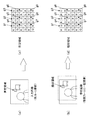
類似度演算部170における類似度算出例を説明する。図2(a)は、画像データSV1による画像を入力画像として示している。この入力画像は、画像データSV1の毎フレームで更新される。図2(b)は、画像データSV6による画像を参照画像として示している。この参照画像は、画像データSV1の複数フレームに一回更新される。
An example of similarity calculation in the
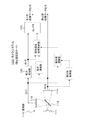
図3は、画像データSV1が60fpsで、画像データSV6が7.5fpsである場合における入力画像と参照画像の更新タイミングを示している。この場合、参照画像は、8フレームに一回更新される。 FIG. 3 shows the update timing of the input image and the reference image when the image data SV1 is 60 fps and the image data SV6 is 7.5 fps. In this case, the reference image is updated once every 8 frames.
類似度演算部170は、画像データSV1の各フレームで、この画像データSV1による画像(入力画像)の所定領域毎に、画像データSV2(参照画像)による画像の類似領域との間の類似度を求める。この実施の形態においては、画像データSV2(参照画像)による画像の類似領域として、この画像データSV2が間引き処理されて得られた画像データSV6による画像の類似領域が参照される。類似度演算部170は、画像データSV1のあるフレームの類似度を求める際には、画像データSV1の当該フレームと、このフレームに対応する画像データSV6のフレームとを用いて、類似度を求める。
The
例えば、図3に示す例の場合、画像データSV1の(1)〜(8)のフレームに対応する画像データSV6のフレームは(1)であり、画像データSV1の(9)〜(16)のフレームに対応する画像データSV6のフレームは(2)である。 For example, in the example shown in FIG. 3, the frame of the image data SV6 corresponding to the frames (1) to (8) of the image data SV1 is (1), and (9) to (16) of the image data SV1. The frame of the image data SV6 corresponding to the frame is (2).
まず、類似度演算部170は、入力画像に対する参照画像の画像全体の動きベクトルを求める。次に、類似度演算部170は、入力画像の所定領域毎に、参照画像の類似領域との間の類似度を求める。ここで、所定領域は、例えば水平x画素、垂直y画素の矩形領域である。入力画像のある所定領域に対応した参照画像の類似領域位置は、当該所定領域を上述の動きベクトルで補正することで得ることができる。なお、図2(b)の破線位置は、入力画像の位置を示している。
First, the
類似度演算部170は、入力画像のある所定領域における参照画像の類似領域との間の類似度を算出する際に、図2(c),(d)に示すように、所定領域および類似領域の対応する複数の画素のデータを用いて算出する。ここでは、図示のように、ベイヤ配列における9個の緑色画素データg1−g9が用いられる。
When calculating the similarity between the reference image and the similar region of the reference image in a predetermined region of the input image, the
まず、類似度演算部170は、所定領域および類似領域の双方において、特徴量1、特徴量2および特徴量3を算出する。特徴量1は、DC成分であり、g1−g9を加算平均して求める。特徴量2は、横方向の高周波成分(縦縞成分)であり、[−1×(g1+g4+g7)]+[+2×(g2+g5+g8)]+[−1×(g3+g6+g9)]のフィルタ演算を行って求める。特徴量3は、縦方向の高周波成分(横縞成分)であり、[−1×(g1+g2+g3)]+[+2×(g4+g5+g6)]+[−1×(g7+g8+g9)]のフィルタ演算を行って求める。
First, the
次に、類似度演算部170は、所定領域および類似領域の双方で求めた特徴量1、特徴量2、特徴量3のそれぞれについて、差分をとり、例えば、図4に示すように、閾値の値で正規化する。そして、類似度演算部170は、この正規化後に1から引くことで、正規化された特徴量とする。
Next, the
次に、類似度演算部170は、正規化された各特徴量を、以下の(1)式のように合成して、類似度を算出する。なお、この(1)式において、α、β、γは、それぞれ、0〜1の範囲の重み係数である。
類似度
=α×(正規化特徴量1)+β×(正規化特徴量2)+γ×(正規化特徴量3)
・・・(1)
Next, the
Similarity = α × (normalized feature amount 1) + β × (normalized feature amount 2) + γ × (normalized feature amount 3)
... (1)
図1に戻って、類似領域加重加算部140は、拡大処理部120で得られた画像データSV3と縮小処理部130で得られた画像データSV4との加重加算を行って、出力画素数(第3の画素数)の画像データSV5を得る。この場合、類似領域加重加算部140は、画像データSV3に対して、この画像データSV3による画像の所定領域毎に、画像データSV4の類似領域の画像データを、類似度演算部170で求められた類似度に応じて加重加算する。この場合、類似度が大きくなるほど、類似領域の画像データの重みが大きくされる。
Returning to FIG. 1, the similar region
ここで、画像データSV3による画像の所定領域およびそれに対応した画像データSV4による画像の類似領域は、上述の類似度演算部170における画像データSV1による画像の所定領域およびそれに対応した類似領域に相当する。ただし、類似領域加重加算部140における各領域は、上述の拡大処理部120における画素数の拡大率に応じて、類似度演算部170における各領域より拡大したものとなる。
Here, the predetermined region of the image based on the image data SV3 and the similar region of the image based on the image data SV4 corresponding thereto correspond to the predetermined region of the image based on the image data SV1 and the similar region corresponding thereto in the
セレクタ150は、拡大処理部120で得られた画像データSV3または類似領域加重加算部140で得られた画像データSV5を選択的に出力する。
The
[カメラシステムの動作]
図1に示すカメラシステム100の動作を説明する。このカメラシステム100は、モニタリングモード、静止画記録モード、動画記録モードの3つの動作モードを有し、ユーザは自由に変更できる。各動作モードについて説明する。
[Camera system operation]
The operation of the camera system 100 shown in FIG. 1 will be described. This camera system 100 has three operation modes of a monitoring mode, a still image recording mode, and a moving image recording mode, and the user can freely change them. Each operation mode will be described.
最初に、モニタリングモードについて説明する。このモニタリングモードでは、画質よりも消費電力を優先させるため、メインイメージセンサ114を休止状態にしつつ、サブイメージセンサ113からの高フレームレートの画像データをモニタ画像データ出力として出力する。
First, the monitoring mode will be described. In this monitoring mode, in order to prioritize power consumption over image quality, high frame rate image data from the
図5は、モニタリングモードにおけるカメラシステム100の各ブロックの処理概要を示している。このモニタリングモードでは、実線で書かれた部分のみ動作し、点線で描かれた部分は休止状態となる。サブイメージセンサ113から高フレームレート(第1のフレームレート)の画像データSV1が出力される。この画像データSV1は、拡大処理部120に供給される。拡大処理部120では、画像データSV1に対して、必要に応じて画素数を拡大する拡大処理が施されて、出力画素数の画像データSV3が生成される。そして、この画像データSV3が、セレクタ150からモニタ画像データ出力として出力される。
FIG. 5 shows an outline of processing of each block of the camera system 100 in the monitoring mode. In this monitoring mode, only the part written with a solid line operates, and the part drawn with a dotted line is in a resting state. The
次に、静止画記録モードについて説明する。この静止画記録モードでは、フレームレートよりも画質を優先させる。図6は、静止画記録モードおけるカメラシステム100の各ブロックの処理概要を示している。この静止画記録モードでは、モニタリングモードで動作するブロックに加えて、メインイメージセンサ114を動作させる。
Next, the still image recording mode will be described. In this still image recording mode, priority is given to image quality over frame rate. FIG. 6 shows a processing outline of each block of the camera system 100 in the still image recording mode. In the still image recording mode, the
サブイメージセンサ113から高フレームレート(第1のフレームレート)の画像データSV1が出力される。この画像データSV1は、拡大処理部120に供給される。拡大処理部120では、画像データSV1に対して、必要に応じて画素数を拡大する拡大処理が施されて、出力画素数の画像データSV3が生成される。そして、この画像データSV3が、セレクタ150からモニタ画像データ出力として出力される。また、メインイメージセンサ114から低フレームレートの画像データSV2が出力される。この画像データSV2は、静止画画像データ出力として出力される。
The
次に、動画記録モードについて説明する。この動画記録モードでは、フレームレートと画質のどちらも重要な要因となる。図7は、動画記録モードおけるカメラシステム100の各ブロックの処理概要を示している。この動画記録モードでは、全てのブロックを動作させる。 Next, the moving image recording mode will be described. In the moving image recording mode, both the frame rate and the image quality are important factors. FIG. 7 shows a processing outline of each block of the camera system 100 in the moving image recording mode. In this moving image recording mode, all blocks are operated.
サブイメージセンサ113から高フレームレート(第1のフレームレート)の画像データSV1が出力される。この画像データSV1は、拡大処理部120に供給される。拡大処理部120では、画像データSV1に対して、必要に応じて画素数を拡大する拡大処理が施されて、出力画素数の画像データSV3が生成される。この画像データSV3は、類似領域加重加算部140に供給される。
The
また、メインイメージセンサ114から低フレームレートの画像データSV2が出力される。この画像データSV2は、縮小処理部130に供給される。縮小処理部130では、画像データSV2に対して、画素数を縮小する縮小処理が施されて、出力画素数の画像データSV4が生成される。この場合、適切な帯域制限フィルタを掛けた上で縮小処理が行われ、折り返しの少ない画像データSV4が生成される。この画像データSV4は、類似領域加重加算部140に供給される。
The
また、サブイメージセンサ113で得られる画像データSV1は、類似度演算部170に供給される。また、メインイメージセンサ114で得られる画像データSV2は、間引き処理部160に供給される。間引き処理部160では、画像データSV2に対して間引き処理が施され、画像データSV1と同じ画素数で、低フレームレート(第2のフレームレート)の画像データSV6が生成される。この画像データSV6は、類似度演算部170に供給される。
The image data SV1 obtained by the
類似度演算部170では、画像データSV1および画像データSV6に基づいて、画像データSV1の各フレームで、この画像データSV1による画像(入力画像)の所定領域毎に、画像データSV2(参照画像)による画像の類似領域との間の類似度が求められる。所定領域毎の類似度の情報および所定領域に対する類似領域の位置情報は、類似領域加重加算部140に供給される。
Based on the image data SV1 and the image data SV6, the
類似領域加重加算部140では、画像データSV3に対して、この画像データSV3による画像の所定領域毎に、画像データSV4の類似領域の画像データが、類似度に応じて加重加算され、出力画素数の画像データSV5が得られる。なお、この類似領域加重加算部140では、画像データSV3による画像の所定領域に対応した、画像データSV4による画像の類似領域は、類似度演算部170から類似度の情報と共に供給される類似領域の位置情報に基づいて把握される。この画像データSV5は、セレクタ150からモニタおよび動画の画像データ出力として出力される。
In the similar area
図8は、上述の動画記録モードにおける、サブイメージセンサ113の出力画像データSV1およびメインイメージセンサ114の出力画像データSV2を処理して画像出力SV5を得るための処理の流れを概略的に示している。
FIG. 8 schematically shows a processing flow for obtaining the image output SV5 by processing the output image data SV1 of the
上述したように、図1に示すカメラシステム100において、動画記録モード時には、類似領域加重加算部140で得られる画像データSV5がセレクタ150を通じて動画像画像出力として出力される(図7参照)。この画像データSV5は、高フレームレートの画像データ(第3の画像データ)SV3に対して、所定画像領域毎に、低フレームレートの画像データ(第4の画像データ)SV4の類似領域の画像データが類似度に応じて加重加算されて得られたものである。
As described above, in the camera system 100 shown in FIG. 1, in the moving image recording mode, the image data SV5 obtained by the similar region
したがって、動画像画像出力として得られる高フレームレートの撮像画像データの画質改善を図ることができる。例えば、サブイメージセンサ113で得られる高フレームレートの画像データSV1が間引き読み出し等による折り返しが含まれた画像データである場合、偽色、ジャギーなどを低減できる。また、例えば、サブイメージセンサ113で得られる高フレームレートの画像データSV1が画素数の少ないイメージセンサから出力された画像データである場合、解像度を向上できる。
Therefore, it is possible to improve the image quality of captured image data at a high frame rate obtained as a moving image output. For example, if the high frame rate image data SV1 obtained by the
また、図1に示すカメラシステム100において、モニタリングモード、静止画録画モード、動画記録モードの3つの動作モードを有している。モニタリングモードでは、サブイメージセンサ113のみの高フレーム低画質動作が行われる。静止画記録モードでは、メインイメージセンサ114とサブイメージセンサ113とが互いに独立した動作が行われる。動画記録モードでは、メインイメージセンサ114およびサブイメージセンサ113の出力の類似度に応じた重ね合わせを行なう画質改善動作が行われる。これらの動作モードを自由に変更できることから、画質とフレームレート、消費電力に応じた動作が可能になる。例えば、モニタリングモード時および静止画記録モード時には、不要なイメージセンサおよびその他の回路部分は休止状態とされる(図5、図6の破線部分参照)。そのため、消費電力の節約を図ることができる。
Further, the camera system 100 shown in FIG. 1 has three operation modes: a monitoring mode, a still image recording mode, and a moving image recording mode. In the monitoring mode, a high frame low image quality operation of only the
また、図1に示すカメラシステム100において、類似度演算部170では、画像データSV1の各フレームで、この画像データSV1による画像の所定領域毎に、画像データSV2の画像データによる画像の類似領域との間の類似度が求められる。この場合、イメージセンサ113で得られる画像データSV1および間引き処理部160で生成された画像データSV6に基づいて、類似度が求められる。この画像データSV6は、画像データSV2に対して間引き処理が施されて得られたものであり、画像データSV1と同じ画素数を持つものとされる。そのため、画像データSV2を直接用いて類似度を求める場合と比べて、所定領域とそれに対応した類似領域のサイズが等しいことから、簡単な処理で、類似度を求めることが可能となる(図2、図4参照)。
In the camera system 100 shown in FIG. 1, the
<2.変形例>
なお、上述実施の形態においては、メインイメージセンサ114で得られる画像データSV2のフレームレートが例えば7.5fpsであるものとして説明した。しかし、メインイメージセンサ114側のフレームレートは自由に変えられるものとしてもよい。その場合、低照度時や動きの少ない被写体の場合には、メインイメージセンサ114側のフレームレート(およびシャッタースピード)をさらに遅くすることで、より低ノイズの参照画像を元に画質改善を図ることができる。
<2. Modification>
In the above embodiment, the frame rate of the image data SV2 obtained by the
図9は、図3に対応した図であり、画像データSV1が60fpsで、画像データSV6が3.75fpsである場合における入力画像と参照画像の更新タイミングを示している。この場合、参照画像は、16フレームに一回更新される。また、この場合、画像データSV2の(1)〜(16)のフレームに対応する画像データSV6のフレームは(1)である。 FIG. 9 is a diagram corresponding to FIG. 3 and shows the update timing of the input image and the reference image when the image data SV1 is 60 fps and the image data SV6 is 3.75 fps. In this case, the reference image is updated once every 16 frames. In this case, the frame of the image data SV6 corresponding to the frames (1) to (16) of the image data SV2 is (1).
また、上述実施の形態においては、サブイメージセンサ113およびメインイメージセンサ114の撮像面に被写体像を結像させるための撮像レンズ111が共通であり、双方のイメージセンサの光学系が同一とされている例を示した。しかし、本技術は、サブイメージセンサ113およびメインイメージセンサ114の撮像面に被写体像を結像させるための撮像レンズが独立し、光学系が共通でない場合であっても適用可能である。
In the above-described embodiment, the
図10は、その場合におけるカメラシステム100Aの構成例を示している。この図10において、図1と対応する部分には同一符号を付し、その詳細説明は省略する。このカメラシステム100Aは、サブイメージセンサ113およびメインイメージセンサ114にそれぞれ対応した撮像レンズ111sおよび撮像レンズ111mを有している。撮像レンズ111sで捉えられた被写体からの光はサブイメージセンサ113に供給され、このサブイメージセンサ113の撮像面に被写体像が結像される。また、撮像レンズ111mで捉えられた被写体からの光はメインイメージセンサ114に供給され、このメインイメージセンサ114の撮像面に被写体像が結像される。このカメラシステム100Aにおけるその他は、図1に示すカメラシステム100と同様に構成されている。
FIG. 10 shows a configuration example of the camera system 100A in that case. 10, parts corresponding to those in FIG. 1 are denoted by the same reference numerals, and detailed description thereof is omitted. The camera system 100A includes an
また、本技術は、以下のような構成を取ることもできる。
(1)第1の画素数の第1の画像データを出力する第1のイメージセンサと、
上記第1の画素数より多い第2の画素数の第2の画像データを出力する第2のイメージセンサと、
上記第1のイメージセンサから出力される上記第1の画像データに基づいて第3の画素数の第3の画像データを生成し、上記第2のイメージセンサから出力される上記第2の画像データに基づいて上記第3の画素数の第4の画像データを生成する画素数変換部と、
上記第1の画像データおよび上記第2の画像データに基づいて、上記第1の画像データと上記第2の画像データによる画像の類似度を求める類似度演算部と、
上記画素数変換部で生成された上記第3の画像データに対して、上記第4の画像データの類似領域の画像データを、上記類似度演算部で求められた類似度に応じて加重加算し、第5の画像データを得る加重加算部とを備える
撮像装置。
(2)第1の動作モードおよび第2の動作モードを有し、
上記第1の動作モードでは、上記第2のイメージセンサから出力される上記第2の画像データを出力し、
上記第2の動作モードでは、上記加重加算部で得られる上記第5の画像データを出力する
前記(1)に記載の撮像装置。
(3)上記第2のイメージセンサから出力される上記第2の画像データに基づいて上記第1の画素数の第6の画像データを生成する間引き処理部をさらに備え、
上記類似度演算部は、
上記第1のイメージセンサから出力される上記第1の画像データおよび上記間引き処理部で生成される上記第6の画像データに基づいて、上記第1の画像データの各フレームで、該第1の画像データによる画像の所定領域毎に、上記第2の画像データによる画像の類似度を求める
前記(1)または(2)に記載の撮像装置。
(4)上記類似度演算部は、
上記第1の画像データおよび上記第6の画像データに基づいて画像全体の動きベクトルを求め、
上記求められた動きベクトルに基づいて、上記第1の画像データの所定領域毎の画像データに対応した上記第6の画像データの類似領域の画像データを求め、
上記第1の画像データの所定領域毎の画像データと、対応する上記第6の画像データの類似領域の画像データに基づいて、上記第1の画像データの各フレームで、該第1の画像データによる画像の所定領域毎に、上記第2の画像データによる画像の類似領域との間の類似度を求める
前記(3)に記載の撮像装置。
(5)上記第1のイメージセンサおよび上記第2のイメージセンサは、光学系が同一とされている
前記(1)から(4)のいずれかに記載の撮像装置。
(6)第1のイメージセンサで得られる第1の画素数の第1の画像データに基づいて第3の画素数の第3の画像データを生成し、第2のイメージセンサで得られる上記第1の画素数より多い第2の画素数の第2の画像データに基づいて上記第3の画素数の第4の画像データを生成する画素数変換ステップと、
上記第1の画像データおよび上記第2の画像データに基づいて、上記第1の画像データと上記第2の画像データによる画像の類似度を求める類似度演算ステップと、
上記画素数変換ステップで生成された上記第3の画像データに対して、上記第4の画像データの類似領域の画像データを、上記類似度演算ステップで求められた類似度に応じて加重加算し、第5の画像データを得る加重加算ステップとを備える
撮像方法。
(7)第1の画素数の第1の画像データに基づいて第3の画素数の第3の画像データを生成し、上記第1の画素数より多い第2の画素数の第2の画像データに基づいて上記第3の画素数の第4の画像データを生成する画素数変換部と、
上記第1の画像データおよび上記第2の画像データに基づいて、上記第1の画像データと上記第2の画像データによる画像の類似度を求める類似度演算部と、
上記画素数変換部で生成された上記第3の画像データに対して、上記第4の画像データの類似領域の画像データを、上記類似度演算部で求められた類似度に応じて加重加算し、第5の画像データを得る加重加算部とを備える
画像処理装置。
Moreover, this technique can also take the following structures.
(1) a first image sensor that outputs first image data having a first number of pixels;
A second image sensor that outputs second image data having a second number of pixels greater than the first number of pixels;
Based on the first image data output from the first image sensor, third image data having a third number of pixels is generated, and the second image data output from the second image sensor. A pixel number conversion unit that generates the fourth image data of the third pixel number based on
Based on the first image data and the second image data, a similarity calculation unit for calculating a similarity between the first image data and the second image data;
The image data in the similar region of the fourth image data is weighted and added to the third image data generated by the pixel number conversion unit according to the similarity obtained by the similarity calculation unit. And a weighted addition unit for obtaining fifth image data.
(2) having a first operation mode and a second operation mode;
In the first operation mode, the second image data output from the second image sensor is output,
The imaging device according to (1), wherein in the second operation mode, the fifth image data obtained by the weighted addition unit is output.
(3) a thinning processing unit that generates sixth image data of the first number of pixels based on the second image data output from the second image sensor;
The similarity calculation unit
Based on the first image data output from the first image sensor and the sixth image data generated by the thinning-out processing unit, the first image data in each frame of the first image data. The imaging device according to (1) or (2), wherein the similarity of the image based on the second image data is obtained for each predetermined region of the image based on the image data.
(4) The similarity calculation unit
Obtaining a motion vector of the entire image based on the first image data and the sixth image data;
Based on the obtained motion vector, obtain image data of a similar region of the sixth image data corresponding to image data for each predetermined region of the first image data,
Based on the image data for each predetermined area of the first image data and the corresponding image data of the similar area of the sixth image data, the first image data in each frame of the first image data The imaging apparatus according to (3), wherein a similarity between the image and the similar region of the image based on the second image data is obtained for each predetermined region of the image.
(5) The imaging apparatus according to any one of (1) to (4), wherein the first image sensor and the second image sensor have the same optical system.
(6) The third image data having the third number of pixels is generated based on the first image data having the first number of pixels obtained by the first image sensor, and the third image data obtained by the second image sensor is obtained. A pixel number conversion step of generating the fourth image data having the third pixel number based on the second image data having the second pixel number larger than the one pixel number;
A similarity calculation step for determining a similarity between the first image data and the second image data based on the first image data and the second image data;
The image data of the similar area of the fourth image data is weighted and added to the third image data generated in the pixel number conversion step according to the similarity obtained in the similarity calculation step. A weighted addition step of obtaining fifth image data.
(7) generating a third image data having a third number of pixels based on the first image data having a first number of pixels, and a second image having a second number of pixels larger than the first number of pixels. A pixel number converter that generates the fourth image data of the third number of pixels based on the data;
Based on the first image data and the second image data, a similarity calculation unit for calculating a similarity between the first image data and the second image data;
The image data in the similar region of the fourth image data is weighted and added to the third image data generated by the pixel number conversion unit according to the similarity obtained by the similarity calculation unit. And a weighted addition unit for obtaining fifth image data.
100,100A・・・カメラシステム
110・・・撮像部
111,111s,111m・・・撮像レンズ
112・・・半透過ミラー
113・・・サブイメージセンサ(第1のイメージセンサ)
114・・・メインイメージセンサ(第2のイメージセンサ)
120・・・拡大処理部
130・・・縮小処理部
140・・・類似領域加重加算部
150・・・セレクタ
160・・・間引き処理部
170・・・類似度演算部
DESCRIPTION OF SYMBOLS 100,100A ... Camera system 110 ...
114 .. Main image sensor (second image sensor)
DESCRIPTION OF
Claims (7)
上記第1の画素数より多い第2の画素数の第2の画像データを出力する第2のイメージセンサと、
上記第1のイメージセンサから出力される上記第1の画像データに基づいて第3の画素数の第3の画像データを生成し、上記第2のイメージセンサから出力される上記第2の画像データに基づいて上記第3の画素数の第4の画像データを生成する画素数変換部と、
上記第1の画像データおよび上記第2の画像データに基づいて、上記第1の画像データと上記第2の画像データによる画像の類似度を求める類似度演算部と、
上記画素数変換部で生成された上記第3の画像データに対して、上記第4の画像データの類似領域の画像データを、上記類似度演算部で求められた類似度に応じて加重加算し、第5の画像データを得る加重加算部とを備える
撮像装置。 A first image sensor that outputs first image data of a first number of pixels;
A second image sensor that outputs second image data having a second number of pixels greater than the first number of pixels;
Based on the first image data output from the first image sensor, third image data having a third number of pixels is generated, and the second image data output from the second image sensor. A pixel number conversion unit that generates the fourth image data of the third pixel number based on
Based on the first image data and the second image data, a similarity calculation unit for calculating a similarity between the first image data and the second image data;
The image data in the similar region of the fourth image data is weighted and added to the third image data generated by the pixel number conversion unit according to the similarity obtained by the similarity calculation unit. And a weighted addition unit for obtaining fifth image data.
上記第1の動作モードでは、上記第2のイメージセンサから出力される上記第2の画像データを出力し、
上記第2の動作モードでは、上記加重加算部で得られる上記第5の画像データを出力する
請求項1に記載の撮像装置。 Having a first operating mode and a second operating mode;
In the first operation mode, the second image data output from the second image sensor is output,
The imaging device according to claim 1, wherein in the second operation mode, the fifth image data obtained by the weighted addition unit is output.
上記類似度演算部は、
上記第1のイメージセンサから出力される上記第1の画像データおよび上記間引き処理部で生成される上記第6の画像データに基づいて、上記第1の画像データの各フレームで、該第1の画像データによる画像の所定領域毎に、上記第2の画像データによる画像の類似度を求める
請求項1に記載の撮像装置。 A thinning-out processing unit for generating sixth image data of the first number of pixels based on the second image data output from the second image sensor;
The similarity calculation unit
Based on the first image data output from the first image sensor and the sixth image data generated by the thinning-out processing unit, the first image data in each frame of the first image data. The imaging device according to claim 1, wherein the similarity of the image based on the second image data is obtained for each predetermined region of the image based on the image data.
上記第1の画像データおよび上記第6の画像データに基づいて画像全体の動きベクトルを求め、
上記求められた動きベクトルに基づいて、上記第1の画像データの所定領域毎の画像データに対応した上記第6の画像データの類似領域の画像データを求め、
上記第1の画像データの所定領域毎の画像データと、対応する上記第6の画像データの類似領域の画像データに基づいて、上記第1の画像データの各フレームで、該第1の画像データによる画像の所定領域毎に、上記第2の画像データによる画像の類似領域との間の類似度を求める
請求項3に記載の撮像装置。 The similarity calculation unit
Obtaining a motion vector of the entire image based on the first image data and the sixth image data;
Based on the obtained motion vector, obtain image data of a similar region of the sixth image data corresponding to image data for each predetermined region of the first image data,
Based on the image data for each predetermined area of the first image data and the corresponding image data of the similar area of the sixth image data, the first image data in each frame of the first image data The imaging apparatus according to claim 3, wherein the degree of similarity between the image and the similar region of the image based on the second image data is obtained for each predetermined region of the image.
請求項1に記載の撮像装置。 The imaging apparatus according to claim 1, wherein the first image sensor and the second image sensor have the same optical system.
上記第1の画像データおよび上記第2の画像データに基づいて、上記第1の画像データと上記第2の画像データによる画像の類似度を求める類似度演算ステップと、
上記画素数変換ステップで生成された上記第3の画像データに対して、上記第4の画像データの類似領域の画像データを、上記類似度演算ステップで求められた類似度に応じて加重加算し、第5の画像データを得る加重加算ステップとを備える
撮像方法。 Based on the first image data of the first number of pixels obtained by the first image sensor, third image data of the third number of pixels is generated, and the first pixel obtained by the second image sensor A pixel number conversion step of generating fourth image data of the third number of pixels based on second image data of a second number of pixels greater than the number;
A similarity calculation step for determining a similarity between the first image data and the second image data based on the first image data and the second image data;
The image data of the similar area of the fourth image data is weighted and added to the third image data generated in the pixel number conversion step according to the similarity obtained in the similarity calculation step. A weighted addition step of obtaining fifth image data.
上記第1の画像データおよび上記第2の画像データに基づいて、上記第1の画像データと上記第2の画像データによる画像の類似度を求める類似度演算部と、
上記画素数変換部で生成された上記第3の画像データに対して、上記第4の画像データの類似領域の画像データを、上記類似度演算部で求められた類似度に応じて加重加算し、第5の画像データを得る加重加算部とを備える
画像処理装置。 Based on the first image data of the first number of pixels, third image data of the third number of pixels is generated, and based on the second image data of the second number of pixels larger than the first number of pixels. A pixel number conversion unit for generating the fourth image data of the third pixel number;
Based on the first image data and the second image data, a similarity calculation unit for calculating a similarity between the first image data and the second image data;
The image data in the similar region of the fourth image data is weighted and added to the third image data generated by the pixel number conversion unit according to the similarity obtained by the similarity calculation unit. And a weighted addition unit for obtaining fifth image data.
Priority Applications (3)
| Application Number | Priority Date | Filing Date | Title |
|---|---|---|---|
| JP2011124055A JP2012253531A (en) | 2011-06-02 | 2011-06-02 | Imaging apparatus, imaging method, and image processing device |
| US13/438,996 US20120307111A1 (en) | 2011-06-02 | 2012-04-04 | Imaging apparatus, imaging method and image processing apparatus |
| CN2012101798876A CN102811314A (en) | 2011-06-02 | 2012-06-01 | Imaging apparatus, imaging method and image processing apparatus |
Applications Claiming Priority (1)
| Application Number | Priority Date | Filing Date | Title |
|---|---|---|---|
| JP2011124055A JP2012253531A (en) | 2011-06-02 | 2011-06-02 | Imaging apparatus, imaging method, and image processing device |
Publications (1)
| Publication Number | Publication Date |
|---|---|
| JP2012253531A true JP2012253531A (en) | 2012-12-20 |
Family
ID=47234882
Family Applications (1)
| Application Number | Title | Priority Date | Filing Date |
|---|---|---|---|
| JP2011124055A Withdrawn JP2012253531A (en) | 2011-06-02 | 2011-06-02 | Imaging apparatus, imaging method, and image processing device |
Country Status (3)
| Country | Link |
|---|---|
| US (1) | US20120307111A1 (en) |
| JP (1) | JP2012253531A (en) |
| CN (1) | CN102811314A (en) |
Cited By (1)
| Publication number | Priority date | Publication date | Assignee | Title |
|---|---|---|---|---|
| JP7495411B2 (en) | 2018-09-18 | 2024-06-04 | インテュイティブ サージカル オペレーションズ, インコーポレイテッド | Method and system for enhanced image sensor timing - Patents.com |
Families Citing this family (2)
| Publication number | Priority date | Publication date | Assignee | Title |
|---|---|---|---|---|
| US9571731B2 (en) * | 2013-08-01 | 2017-02-14 | Corephotonics Ltd. | Thin multi-aperture imaging system with auto-focus and methods for using same |
| US9672594B2 (en) | 2014-10-21 | 2017-06-06 | The Boeing Company | Multiple pixel pitch super resolution |
Family Cites Families (4)
| Publication number | Priority date | Publication date | Assignee | Title |
|---|---|---|---|---|
| US20050219642A1 (en) * | 2004-03-30 | 2005-10-06 | Masahiko Yachida | Imaging system, image data stream creation apparatus, image generation apparatus, image data stream generation apparatus, and image data stream generation system |
| US7692696B2 (en) * | 2005-12-27 | 2010-04-06 | Fotonation Vision Limited | Digital image acquisition system with portrait mode |
| JP4215266B2 (en) * | 2006-10-30 | 2009-01-28 | パナソニック株式会社 | Image generating apparatus and image generating method |
| JP4689687B2 (en) * | 2008-01-29 | 2011-05-25 | 株式会社モルフォ | Imaging method and imaging apparatus |
-
2011
- 2011-06-02 JP JP2011124055A patent/JP2012253531A/en not_active Withdrawn
-
2012
- 2012-04-04 US US13/438,996 patent/US20120307111A1/en not_active Abandoned
- 2012-06-01 CN CN2012101798876A patent/CN102811314A/en active Pending
Cited By (1)
| Publication number | Priority date | Publication date | Assignee | Title |
|---|---|---|---|---|
| JP7495411B2 (en) | 2018-09-18 | 2024-06-04 | インテュイティブ サージカル オペレーションズ, インコーポレイテッド | Method and system for enhanced image sensor timing - Patents.com |
Also Published As
| Publication number | Publication date |
|---|---|
| US20120307111A1 (en) | 2012-12-06 |
| CN102811314A (en) | 2012-12-05 |
Similar Documents
| Publication | Publication Date | Title |
|---|---|---|
| JP4509917B2 (en) | Image processing apparatus and camera system | |
| US9210391B1 (en) | Sensor data rescaler with chroma reduction | |
| US9787922B2 (en) | Pixel defect preprocessing in an image signal processor | |
| US8072511B2 (en) | Noise reduction processing apparatus, noise reduction processing method, and image sensing apparatus | |
| US20100074520A1 (en) | Image processing device and image processing method | |
| JPWO2017014071A1 (en) | Camera module, solid-state imaging device, electronic device, and imaging method | |
| US8861846B2 (en) | Image processing apparatus, image processing method, and program for performing superimposition on raw image or full color image | |
| JP4317587B2 (en) | IMAGING PROCESSING DEVICE, IMAGING DEVICE, IMAGE PROCESSING METHOD, AND COMPUTER PROGRAM | |
| KR20180037008A (en) | Multi-rate processing of image data within an image processing pipeline | |
| JP2007180734A (en) | Image processor, camera system, image processing method and moving image display method | |
| JP2011097246A (en) | Image processing apparatus, method, and program | |
| US8982248B2 (en) | Image processing apparatus, imaging apparatus, image processing method, and program | |
| JP2011097568A (en) | Image sensing apparatus | |
| EP2847998B1 (en) | Systems, methods, and computer program products for compound image demosaicing and warping | |
| JP6087612B2 (en) | Image processing apparatus and image processing method | |
| US20240169481A1 (en) | Demosaicing circuit for demosaicing quad bayer raw image data | |
| JP2009055410A (en) | Image processing device and image processing method | |
| JP2012142827A (en) | Image processing device and image processing method | |
| US11936992B2 (en) | Multi-mode demosaicing for raw image data | |
| KR20230124699A (en) | Circuitry for Combined Downsampling and Correction of Image Data | |
| JP2012253531A (en) | Imaging apparatus, imaging method, and image processing device | |
| JP6029294B2 (en) | Video presentation apparatus and video presentation program | |
| JP5748513B2 (en) | Imaging device | |
| JP2008072428A (en) | Image processor, electronic camera, and image processing program | |
| JP6516574B2 (en) | Image blur correction device, imaging device, image blur correction method |
Legal Events
| Date | Code | Title | Description |
|---|---|---|---|
| A300 | Application deemed to be withdrawn because no request for examination was validly filed |
Free format text: JAPANESE INTERMEDIATE CODE: A300 Effective date: 20140805 |