JP2012253501A - Radio communication system, road-side communication equipment therefor, and synchronization method - Google Patents
Radio communication system, road-side communication equipment therefor, and synchronization method Download PDFInfo
- Publication number
- JP2012253501A JP2012253501A JP2011123492A JP2011123492A JP2012253501A JP 2012253501 A JP2012253501 A JP 2012253501A JP 2011123492 A JP2011123492 A JP 2011123492A JP 2011123492 A JP2011123492 A JP 2011123492A JP 2012253501 A JP2012253501 A JP 2012253501A
- Authority
- JP
- Japan
- Prior art keywords
- time
- transmission
- communication device
- roadside communication
- transmission signal
- Prior art date
- Legal status (The legal status is an assumption and is not a legal conclusion. Google has not performed a legal analysis and makes no representation as to the accuracy of the status listed.)
- Pending
Links
Images


Landscapes
- Traffic Control Systems (AREA)
- Mobile Radio Communication Systems (AREA)
Abstract
Description
本発明は、例えば、高度道路交通システム(ITS:Intelligent Transport System)に好適に用いられる無線通信システム、及びこれに用いる路側通信機、同期方法に関する。 The present invention relates to, for example, a wireless communication system suitably used for an intelligent transport system (ITS), a roadside communication device used for the wireless communication system, and a synchronization method.
近年、交通安全の促進や交通事故の防止を目的として、道路に設置されたインフラ装置からの情報を受信し、或いは車両同士で情報交換を行い、これらの情報を活用することで車両の安全性を向上させる高度道路交通システムが検討されている(例えば、特許文献1参照)。
かかる高度道路交通システムは、主として、インフラ側の無線通信装置である複数の路側通信機と、各車両に搭載される無線通信装置である複数の車載通信機とによって構成される。
In recent years, for the purpose of promoting traffic safety and preventing traffic accidents, vehicle safety has been achieved by receiving information from infrastructure devices installed on roads or exchanging information between vehicles and utilizing these information. An intelligent road traffic system that improves the above has been studied (for example, see Patent Document 1).
Such an intelligent road traffic system is mainly composed of a plurality of roadside communication devices which are wireless communication devices on the infrastructure side and a plurality of in-vehicle communication devices which are wireless communication devices mounted on each vehicle.
この場合、各通信主体間で行う通信の組み合わせには、路側通信機同士が行う路路間通信と、路側通信機と車載通信機とが行う路車(又は車路)間通信と、車載通信機同士が行う車車間通信とが含まれる。 In this case, a combination of communication performed between communication subjects includes road-to-road communication between road-side communication devices, road-to-vehicle (or vehicle-road) communication between road-side communication devices and vehicle-mounted communication devices, and vehicle-mounted communication. Vehicle-to-vehicle communication performed between aircraft.
上記高度道路交通システムにおいては、車車間通信をはじめ、路車間通信や路路間通信及び路歩間通信も含め、これらの各通信の共存を図るに当たって、限られた周波数帯域内で路路間、路車間及び車車間の各通信を行うために、通信を行う時間を分割して路側通信機の送信専用のタイムスロットを設ける、時分割多重(TDMA:Time Division Multiple Access)によるマルチアクセス方式を採用している。
上記TDMAによるマルチアクセス方式において、送信用タイムスロットは、通常、各通信機それぞれに対して周期的に設定される。このため、各路側通信機は、周期的に設定された自機の送信用タイムスロットを用いて送信を行い、それ以外の時間は、他の路側機又は車載通信機からの送信信号の受信を行う。
In the above-mentioned intelligent road traffic system, road-to-vehicle communication, road-to-road communication, road-to-road communication, and road-to-step communication, including road-to-vehicle communication, can be carried out between roads within a limited frequency band. In order to perform each communication between road vehicles and between vehicles, a multi-access method by time division multiple access (TDMA) that divides the time for communication and provides a time slot dedicated to transmission of the roadside communication device. Adopted.
In the multi-access scheme based on TDMA, transmission time slots are normally set periodically for each communication device. For this reason, each roadside communication device performs transmission using its own transmission time slot that is set periodically, and at other times it receives transmission signals from other roadside devices or in-vehicle communication devices. Do.
上記システムがTDMAによるマルチアクセス方式を採用した場合、路側通信機同士及び路側通信機と車載通信機とで正確に時刻が同期していないと、各路側通信機及び車載通信機が把握するタイムスロットの開始時刻にずれが生じ、各通信機間で干渉を生じさせるおそれがある。 When the above system adopts the multi-access method by TDMA, if the time is not accurately synchronized between roadside communication devices and between the roadside communication device and the in-vehicle communication device, the time slot that each roadside communication device and the in-vehicle communication device grasps There is a possibility that a difference occurs in the start time of the communication, causing interference between the communication devices.
そこで、移動する車載通信機は、近傍の路側通信機からの送信信号に基づいて自機の時刻を補正することで路側通信機に同期し、路側通信機は、自機の時刻を補正することで他の路側通信機との間で同期することが考えられる。各路側通信機が同期していれば、車載通信機は、近傍の路側通信機に同期することで、他の路側通信機との間においても同期することができる。 Therefore, the moving in-vehicle communication device is synchronized with the roadside communication device by correcting the time of the own device based on the transmission signal from the nearby roadside communication device, and the roadside communication device corrects the time of the own device. It is possible to synchronize with other roadside communication devices. If each roadside communication device is synchronized, the in-vehicle communication device can be synchronized with other roadside communication devices by synchronizing with a nearby roadside communication device.
ここで、各路側通信機が互いに同期するためには、例えば、GPS(Global Positioning System)を利用して各路側通信機ごとに所定の基準時刻に基づいて自機のローカル時刻を補正する方法(GPS同期)や、自機のローカル時刻を、他の路側通信機から通知される時刻情報に基づいて補正する方法(エア同期)が考えられる。 Here, in order for each roadside communication device to synchronize with each other, for example, a method of correcting the local time of its own device based on a predetermined reference time for each roadside communication device using GPS (Global Positioning System) ( (GPS synchronization) and a method of correcting the local time of the own device based on time information notified from other roadside communication devices (air synchronization) can be considered.
上記GPS同期は、無線通信が困難な程度に離れた路側通信機同士の同期も可能という特長を持つが、各路側通信機それぞれにGPSを搭載しなければならず、コストアップに繋がる。
これに対して、エア同期では、路側通信機が備えている通信機能を用いて路側通信機同士で時刻情報を通知しあうことで同期を行うことができるので、コスト面で有利であるとともに、簡易な構成で路側通信機間の同期を行うことができる。
両同期方法は、それぞれ上述のような特長を有しているが、各路側通信機が互いに同期するための方法としては、GPS同期とエア同期を併用することが好ましい。
The GPS synchronization described above has a feature that it is possible to synchronize roadside communication devices that are separated to such a degree that wireless communication is difficult, but each roadside communication device must be equipped with a GPS, leading to an increase in cost.
In contrast, air synchronization is advantageous in terms of cost because it can synchronize by notifying time information between roadside communication devices using the communication function provided by the roadside communication device, Synchronization between roadside communication devices can be performed with a simple configuration.
Both synchronization methods have the above-described features, but it is preferable to use both GPS synchronization and air synchronization as a method for the roadside communication devices to synchronize with each other.
図9は、従来の路側通信機がエア同期を行う手順を示すシーケンス図である。図9中、路側通信機101に着目して説明すると、まず、路側通信機101は、同期先となる他の路側通信機を特定する(ステップS51)。ここでは、路側通信機101は、同期先として路側通信機102を特定している。そして、同期先からの送信信号に含まれる時刻情報を取得する。そして、自機のローカル時刻と同期先から通知される時刻とのずれを求め(ステップS52)、そのずれが解消されるように、自機のローカル時刻を補正する(ステップS53)。 FIG. 9 is a sequence diagram illustrating a procedure in which the conventional roadside communication device performs air synchronization. In FIG. 9, the description will be made with attention paid to the roadside communication device 101. First, the roadside communication device 101 identifies another roadside communication device as a synchronization destination (step S51). Here, the roadside communication device 101 specifies the roadside communication device 102 as a synchronization destination. Then, time information included in the transmission signal from the synchronization destination is acquired. Then, the difference between the local time of the own device and the time notified from the synchronization destination is obtained (step S52), and the local time of the own device is corrected so that the difference is eliminated (step S53).
複数の路側通信機の間で相互にエア同期を行い、継続的に各路側通信機の時刻補正を行えば、各路側通信機の時刻は、ある時刻に収束して相互の時刻ずれが解消され、各路側通信機が互いに同期した状態に至ると考えられる。 If you synchronize air between multiple roadside communicators and continuously correct the time of each roadside communicator, the time of each roadside communicator converges to a certain time and the mutual time lag is resolved. The roadside communication devices are considered to be in a synchronized state.
ここで実際には、図9中の路側通信機101,102のように、二つの路側通信機が、互いを同期先として特定し、エア同期を行うことも想定される。
この場合、路側通信機101及び路側通信機102が、相互に時刻補正前の時刻情報を取得し、この時刻情報から認識された時刻ずれに基づいて時刻補正を行うと、互いに同期先の補正前の時刻に一致させようと補正することとなる。すると、相互にローカル時刻の進み遅れが反転してしまい、両者の時刻ずれは解消されないという事態が生じる。
Actually, it is also assumed that two roadside communication devices specify each other as synchronization destinations and perform air synchronization, such as roadside communication devices 101 and 102 in FIG.
In this case, when the roadside communication device 101 and the roadside communication device 102 mutually acquire the time information before the time correction and perform the time correction based on the time difference recognized from the time information, the synchronization destination before the correction of the synchronization destination is performed. It will be corrected to match the time of Then, the advance / delay of the local time is reversed, and the time lag between the two cannot be resolved.
図9に示す路側通信機101では、路側通信機102の時刻に対して時刻ずれが生じていることを認識しているにもかかわらず、路側通信機102に対して時刻補正せずに時刻情報を通知し、かつ、路側通信機102が時刻補正をしているか否かに関わらず時刻補正を行うので、路側通信機102との間で時刻ずれが解消されない事態になる可能性を生じさせる。 The roadside communication device 101 shown in FIG. 9 recognizes that a time lag has occurred with respect to the time of the roadside communication device 102, but the time information is not corrected for the roadside communication device 102. , And the time correction is performed regardless of whether or not the roadside communication device 102 is correcting the time, so that there is a possibility that the time difference between the roadside communication device 102 and the roadside communication device 102 cannot be resolved.
つまり、図9に示すように、路側通信機101が、路側通信機102の時刻に対して時刻がずれていることを認識しているにもかかわらず、送信信号を未補正のまま送信すると、路側通信機102の時刻を認識(取得)したタイミング以後の路側通信機102の時刻が、当該路側通信機102による時刻補正によって変動してしまう可能性を生じさせる。このため、路側通信機101が認識している路側通信機102の時刻と、実際の路側通信機102の時刻とが異なってしまい、相互に時刻ずれが解消されない事態になる。 That is, as shown in FIG. 9, when the roadside communication device 101 recognizes that the time is shifted with respect to the time of the roadside communication device 102 and transmits the transmission signal without correction, There is a possibility that the time of the roadside communication device 102 after the timing at which the time of the roadside communication device 102 is recognized (acquired) will fluctuate due to time correction by the roadside communication device 102. For this reason, the time of the roadside communication device 102 recognized by the roadside communication device 101 is different from the time of the actual roadside communication device 102, and the time lag is not eliminated.
上記のような事態が生じる可能性が有ると、各路側通信機間で継続的にエア同期を行ったとしても、各路側通信機の時刻は収束せず、相互の時刻ずれを解消することができない。 If there is a possibility that the above situation may occur, even if air synchronization is continuously performed between the roadside communication devices, the time of each roadside communication device does not converge and the mutual time lag can be resolved. Can not.
本発明はこのような事情に鑑みてなされたものであり、複数の路側通信機の間で相互に同期を行ったとしても、確実に相互の時刻ずれを解消することができる無線通信システム、及びこれに用いる路側通信機、同期方法を提供することを目的とする。 The present invention has been made in view of such circumstances, and even when a plurality of roadside communication devices synchronize with each other, a wireless communication system that can reliably eliminate the mutual time lag, and It is an object of the present invention to provide a roadside communication device and a synchronization method used for this.
(1)本発明は、時分割により設定された複数の送信用タイムスロットが、複数の路側通信機それぞれに割り当てられ、前記路側通信機は、当該路側通信機間の同期に用いられる時刻情報を送信信号に含めて送信する無線通信システムであって、前記路側通信機は、同期先となる他の路側通信機を特定する同期先特定部と、前記同期先となる他の路側通信機からの送信信号に含まれる前記時刻情報に基づいて、自機の時刻を補正する補正部と、自機の時刻に基づいた前記時刻情報を含む送信信号を、自機に割り当てられた前記送信タイムスロットを用いて送信する送信部と、を備えており、前記補正部は、前記送信部が前記時刻情報を含む前記送信信号を送信してから次に前記時刻情報を含む送信信号を送信するまでの送信インターバルの間に、前記同期先となる他の路側通信機から前記時刻情報を含む送信信号を受信すると、当該送信インターバルの間に、受信した前記時刻情報に基づく、自機の時刻の補正を行い、前記送信部は、前記送信インターバル直後に送信する送信信号には、当該送信インターバルの間に補正した補正後の時刻に基づく前記時刻情報を含めて送信することを特徴としている。 (1) In the present invention, a plurality of transmission time slots set by time division are allocated to a plurality of roadside communication devices, and the roadside communication device stores time information used for synchronization between the roadside communication devices. A wireless communication system that includes a transmission signal for transmission, wherein the roadside communication device includes a synchronization destination specifying unit that specifies another roadside communication device that is a synchronization destination, and another roadside communication device that is the synchronization destination. Based on the time information included in the transmission signal, a correction unit that corrects the time of the own device, and a transmission signal including the time information based on the time of the own device, the transmission time slot assigned to the own device And the transmission unit transmits the transmission signal including the time information until the next transmission signal including the time information is transmitted. During the interval When the transmission signal including the time information is received from the other roadside communication device serving as the synchronization destination, the time of the own device is corrected based on the received time information during the transmission interval, and the transmission unit The transmission signal transmitted immediately after the transmission interval includes the time information based on the corrected time corrected during the transmission interval.
上記のように構成された無線通信システムによれば、路側通信機が、送信インターバルの間に、同期先である他の路側通信機から時刻情報を含む送信信号を受信すると、その時刻情報に基づいて自機の時刻の補正を行う補正部と、送信インターバル直後に送信する送信信号には、当該送信インターバルの間に補正した補正後の時刻に基づく時刻情報を含めて送信する送信部とを備えているので、仮に、二つの路側通信機が互いを同期先として特定した場合であっても、一の路側通信機が取得する同期先である他の路側通信機からの時刻情報は、他の路側通信機からの送信信号を受信する直前に一の路側通信機が送信した時刻情報に基づいて補正されている。このため、一の路側通信機は、他の路側通信機の補正後の時刻に基づいて自機の時刻を補正することができ、両方の路側通信機が、互いの補正前の時刻情報に基づいて自機の時刻を補正することで、相互間の時刻ずれを解消することができなくなるといった事態を回避することができる。この結果、複数の路側通信機の間で相互に同期を行ったとしても、確実に相互の時刻ずれを解消することができる。 According to the wireless communication system configured as described above, when a roadside communication device receives a transmission signal including time information from another roadside communication device that is a synchronization destination during a transmission interval, it is based on the time information. A correction unit that corrects the time of the device itself, and a transmission unit that transmits the transmission signal transmitted immediately after the transmission interval including time information based on the corrected time corrected during the transmission interval. Therefore, even if the two roadside communication devices specify each other as the synchronization destination, the time information from the other roadside communication device that is the synchronization destination acquired by the one roadside communication device is the other Correction is performed based on time information transmitted by one roadside communication device immediately before receiving a transmission signal from the roadside communication device. For this reason, one roadside communication device can correct its own time based on the corrected time of the other roadside communication devices, and both roadside communication devices are based on the time information before correction of each other. By correcting the time of the own machine, it is possible to avoid a situation in which the time lag between the two cannot be eliminated. As a result, even if a plurality of roadside communication devices synchronize with each other, the mutual time lag can be reliably resolved.
(2)上記無線通信システムにおいて、路側通信機は、同期先である他の路側通信機からの送信信号を受信した後、自機が送信信号を送信するまでの間に、同期先の時刻情報に基づいて自機の時刻を補正する必要がある。
これに対して、前記複数の送信用タイムスロットそれぞれの間には、道路上の移動通信機に割り当てられる移動通信機用タイムスロットが設定されていることが好ましい。
この場合、一の路側通信機は、同期先から送信信号を受信した後、自機が送信信号を送信するまでの間に、少なくとも移動通信機用タイムスロットが介在するので、同期先からの送信信号を受信した後、自機が送信信号を送信するまでの間に、同期先の時刻情報に基づいて自機の時刻を補正するための期間を十分に確保することができる。
(2) In the above wireless communication system, the roadside communication device receives the transmission signal from the other roadside communication device that is the synchronization destination, and until the own device transmits the transmission signal, the synchronization destination time information It is necessary to correct the time of the aircraft based on the above.
In contrast, it is preferable that a mobile communication device time slot assigned to a mobile communication device on the road is set between each of the plurality of transmission time slots.
In this case, since one roadside communication device receives at least a mobile communication device time slot after receiving a transmission signal from the synchronization destination until the own device transmits the transmission signal, transmission from the synchronization destination is performed. It is possible to secure a sufficient period for correcting the time of the own device based on the time information of the synchronization destination after the signal is received and before the own device transmits the transmission signal.
(3)また、前記同期先特定部は、前記複数の路側通信機それぞれの送信信号を複数回受信して得られる受信品質に基づいて前記同期先となる他の路側通信機を特定するものであってもよく、この場合、より通信状態の良好な路側通信機を同期先として特定でき、より確実に同期を行うことができる。 (3) Further, the synchronization destination specifying unit specifies the other roadside communication device that is the synchronization destination based on reception quality obtained by receiving the transmission signals of the plurality of roadside communication devices a plurality of times. In this case, a roadside communication device having a better communication state can be specified as a synchronization destination, and synchronization can be more reliably performed.
(4)また、本発明は、時分割により設定された複数の送信用タイムスロットが割り当てられるとともに、同期に用いられる時刻情報を送信信号に含めて送信する路側通信機であって、同期先となる他の路側通信機を特定する同期先特定部と、前記同期先となる他の路側通信機からの送信信号に含まれる前記時刻情報に基づいて、自機の時刻を補正する補正部と、自機の時刻に基づいた前記時刻情報を含む送信信号を、自機に割り当てられた前記送信タイムスロットを用いて送信する送信部と、を備えており、前記補正部は、前記送信部が前記時刻情報を含む前記送信信号を送信してから次に前記時刻情報を含む送信信号を送信するまでの送信インターバルの間に、前記同期先となる他の路側通信機から前記時刻情報を含む送信信号を受信すると、当該送信インターバルの間に、受信した前記時刻情報に基づく、自機の時刻の補正を行い、前記送信部は、前記送信インターバル直後に送信する送信信号には、当該送信インターバルの間に補正した補正後の時刻に基づく前記時刻情報を含めて送信することを特徴としている。 (4) Further, the present invention is a roadside communication device that is assigned a plurality of transmission time slots set by time division and transmits time information used for synchronization in a transmission signal, A synchronization destination identifying unit that identifies the other roadside communication device, and a correction unit that corrects the time of the own device based on the time information included in the transmission signal from the other roadside communication device that is the synchronization destination, A transmission unit that transmits the transmission signal including the time information based on the time of the own device using the transmission time slot assigned to the own device, and the correction unit includes the transmission unit The transmission signal including the time information from the other roadside communication device serving as the synchronization destination during a transmission interval from the transmission of the transmission signal including the time information to the next transmission of the transmission signal including the time information Receive Then, during the transmission interval, the time of the own device is corrected based on the received time information, and the transmission unit corrects the transmission signal transmitted immediately after the transmission interval during the transmission interval. The time information based on the corrected time is transmitted including the time information.
(5)また、本発明は、時分割により設定された複数の送信用タイムスロットが、複数の路側通信機それぞれに割り当てられ、前記路側通信機は、当該路側通信機間の同期に用いられる時刻情報を送信信号に含めて送信する無線通信システムの同期方法であって、同期先となる他の路側通信機を特定する同期先特定ステップと、前記同期先となる他の路側通信機からの送信信号に含まれる前記時刻情報に基づいて、時刻を補正する補正ステップと、自機の時刻に基づいた前記時刻情報を含む送信信号を、自機に割り当てられた前記送信タイムスロットを用いて送信する送信ステップと、を備え、前記補正ステップは、前記送信ステップによって前記時刻情報を含む前記送信信号を送信してから次に前記時刻情報を含む送信信号を送信する次の送信ステップまでの送信インターバルの間に、前記同期先となる他の路側通信機から前記時刻情報を含む送信信号を受信すると、当該送信インターバルの間に、受信した前記時刻情報に基づく、自機の時刻の補正を行うものであり、前記送信ステップは、前記送信インターバル直後に送信する送信信号には、当該送信インターバルの間に補正した補正後の時刻に基づく前記時刻情報を含めて送信することを特徴としている。 (5) Further, according to the present invention, a plurality of transmission time slots set by time division are allocated to a plurality of roadside communication devices, and the roadside communication devices are used for synchronization between the roadside communication devices. A synchronization method of a wireless communication system for transmitting information including a transmission signal, the synchronization destination specifying step for specifying another roadside communication device as a synchronization destination, and transmission from the other roadside communication device as the synchronization destination A correction step for correcting the time based on the time information included in the signal and a transmission signal including the time information based on the time of the own device are transmitted using the transmission time slot assigned to the own device. A transmitting step, wherein the correcting step transmits the transmission signal including the time information by the transmitting step, and then transmits the transmission signal including the time information next. When the transmission signal including the time information is received from the other roadside communication device that is the synchronization destination during the transmission interval up to the transmission step, based on the received time information during the transmission interval, The transmission step includes transmitting the transmission signal transmitted immediately after the transmission interval including the time information based on the corrected time corrected during the transmission interval. It is a feature.
上記のように構成された路側通信機、及び同期方法によれば、複数の路側通信機の間で相互に同期を行ったとしても、確実に相互の時刻ずれを解消することができる。 According to the roadside communication device and the synchronization method configured as described above, even if the plurality of roadside communication devices synchronize with each other, it is possible to reliably eliminate the mutual time lag.
本発明によれば、複数の路側通信機の間で相互に同期を行ったとしても、確実に相互の時刻ずれを解消することができる。 According to the present invention, even if a plurality of roadside communication devices synchronize with each other, the mutual time lag can be reliably eliminated.
〔システムの全体構成〕
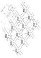
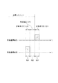
図1は、本発明の一実施形態に係る高度道路交通システム(ITS)の全体構成を示す概略斜視図である。なお、本実施形態では、道路構造の一例として、南北方向と東西方向の複数の道路が互いに交差した碁盤目構造を想定している。
図1に示すように、本実施形態の高度道路交通システムは、交通信号機1、路側通信機2、車載通信機3(図3参照)、中央装置4、車載通信機3を搭載した車両5、及び、車両感知器や監視カメラ等よりなる路側センサ6を含む。
[Overall system configuration]
FIG. 1 is a schematic perspective view showing an overall configuration of an intelligent road traffic system (ITS) according to an embodiment of the present invention. In this embodiment, as an example of the road structure, a grid structure in which a plurality of roads in the north-south direction and the east-west direction intersect with each other is assumed.
As shown in FIG. 1, the intelligent transportation system of this embodiment includes a
交通信号機1と路側通信機2は、複数の交差点Ji(図例では、i=1〜12)のそれぞれに設置されており、電話回線等の通信回線7を介してルータ8に接続されている。このルータ8は交通管制センター内の中央装置4に接続されている。
中央装置4は、自身が管轄するエリアに含まれる各交差点Jiの交通信号機1及び路側通信機2とLAN(Local Area Network)を構成している。従って、中央装置4は、各交通信号機1及び各路側通信機2との間で双方向通信が可能である。なお、中央装置4は、交通管制センターではなく道路上に設置してもよい。
The
The
路側センサ6は、各交差点Jiに流入する車両台数をカウントする等の目的で、管轄エリア内の道路の各所に設置されている。この路側センサ6は、直下を通行する車両5を超音波感知する車両感知器、或いは、道路の交通状況を時系列に撮影する監視カメラ等よりなり、感知情報S4や画像データS5は通信回線7を介して中央装置4に送信される。
なお、図1では、図示を簡略化するために、各交差点Jiに信号灯器が1つだけ描写されているが、実際の各交差点Jiには、互いに交差する道路の上り下り用として少なくとも4つの信号灯器が設置されている。
The
In FIG. 1, for simplification of illustration, only one signal lamp is depicted at each intersection Ji, but at each actual intersection Ji, there are at least four for ascending and descending roads intersecting each other. A signal lamp is installed.
〔中央装置〕
中央装置4は、ワークステーション(WS)やパーソナルコンピュータ(PC)等よりなる制御部を有しており、この制御部は、路側通信機2、路側センサ6からの各種の交通情報の収集・処理(演算)・記録、信号制御及び情報提供を統括的に行う。
具体的には、中央装置4の制御部は、自身のネットワークに属する交差点Jiの交通信号機1に対して、同一道路上の交通信号機1群を調整する系統制御や、この系統制御を道路網に拡張した広域制御(面制御)を行うことができる。
[Central equipment]
The
Specifically, the control unit of the
また、中央装置4は、通信回線7を介してLAN側と接続された通信インタフェースである通信部を有しており、この通信部は、信号灯器の灯色切り替えタイミングに関する信号制御指令S1や、渋滞情報等を含む交通情報S2を所定時間ごとに交通信号機1及び路側通信機2に送信している(図1参照)。
In addition, the
信号制御指令S1は、前記系統制御や広域制御を行う場合の信号制御パラメータの演算周期(例えば、1.0〜2.5分)ごとに送信され、交通情報S2は、例えば5分ごとに送信される。 The signal control command S1 is transmitted every calculation period (for example, 1.0 to 2.5 minutes) of the signal control parameter when performing the system control and the wide area control, and the traffic information S2 is transmitted every 5 minutes, for example. Is done.
また、中央装置4の通信部は、各交差点Jiに対応する路側通信機2から、その通信機2が車載通信機3から受信した車両5の現在位置等を含む車両情報S3、車両通過時に生じるパルス信号よりなる車両感知器(図示せず)の感知情報S4、及び、監視カメラが撮影した道路のデジタル情報よりなる画像データS5等を受信しており、中央装置4の制御部は、これらの各種情報に基づいて前記系統制御や広域制御を実行する。
Further, the communication unit of the
〔無線通信の方式等〕
高度道路交通システムにおいて、無線通信システムを構成する、複数の交差点それぞれに設置された複数の路側通信機2は、その周囲を走行する車両の車載通信機3との間で無線通信(路車(車路)間通信)が可能である。また、各路側通信機2は、自己の送信波が到達する所定範囲内に位置する他の路側通信機2とも無線通信(路路間通信)が可能である。
また、同じく無線通信システムを構成する車載通信機3は、路側通信機2との間で無線通信を行うとともに、キャリアセンス方式で他の車載通信機3と無線通信(車車間通信)が可能である。
[Wireless communication systems, etc.]
In an intelligent road traffic system, a plurality of
The in-
このように、本実施形態のITSでは、車載通信機3同士(車車間通信)の通信と、路側通信機2と車載通信機3との間(「路」から「車」への路車間通信と「車」から「路」への車路間通信との双方を含む。)の通信については、無線通信が用いられている。
なお、交通管制センターに設けられた中央装置4は、各路側通信機2と有線での双方向通信が可能であるが、これらの間も無線通信であってもよい。
As described above, in the ITS of this embodiment, communication between the vehicle-mounted communication devices 3 (vehicle-to-vehicle communication) and communication between the road-
In addition, although the
路側通信機2には、自身が無線送信するための専用のタイムスロット(図2の第1スロットSL1)がTDMA方式で割り当てられており、このタイムスロット以外の時間帯(図2の第2スロットSL2)には無線送信を行わない。すなわち、路側通信機2用のタイムスロット以外の時間帯は、車載通信機3のためのCSMA方式による送信時間として開放されている。
路側通信機2及び車載通信機3は、同一周波数帯を通信に用いるが、上記のように路側通信機2と車載通信機3の送信時間帯が区別されていることで、路側通信機2による送信信号と、車載通信機3による送信信号との衝突を回避できる。
The
Although the
路側通信機2及び車載通信機3は、送信信号の受信に関しては特に制限されない。従って、路側通信機2は、車載通信機3の送信信号を受信できる他、他の路側通信機2の送信信号も受信できる。また、車載通信機3は、路側通信機2及び他の車載通信機3の送信信号を受信できる。
The
〔タイムスロットの内容〕
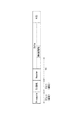
図2は、本実施形態における路車間通信のタイムスロットの一例を示す概念図である。図2に示すように、路車間通信においては、時間軸方向に並べて配置される無線フレームが用いられている。
この無線フレームは、その時間軸方向の長さが100ミリ秒に設定されており、第一スロットSL1と、第二スロットSL2とを含んで構成されている。
第一スロットSL1は、路側通信機2に割り当てられるタイムスロットであり、この時間帯においては、路側通信機2による無線送信が許容される。一方、第2スロットSL2は、車載通信機3用のタイムスロットであり、この時間帯は車載通信機3による無線送信用として開放するため、路側通信機2は第2スロットSL2では無線送信を行わない。
[Contents of time slot]
FIG. 2 is a conceptual diagram showing an example of a time slot for road-to-vehicle communication in the present embodiment. As shown in FIG. 2, in the road-to-vehicle communication, radio frames arranged side by side in the time axis direction are used.
This radio frame has a length in the time axis direction set to 100 milliseconds, and includes a first slot SL1 and a second slot SL2.
The first slot SL1 is a time slot assigned to the
無線フレームに含まれている第一スロットSL1と、第2スロットSL2とは、時間軸方向に交互に配置されている。
第一スロットSL1には、それぞれスロット番号i(図2では、i=1〜10)が付されている。このスロット番号iは、無線フレーム内でインクリメント又はデクリメントされる。
路側通信機2には、無線フレームに含まれる複数の第一スロットSL1の内の一つが割り当てられる。路側通信機2はスロット番号iによっていずれのスロットが自機に割り当てられるかを認識することができる。
無線フレームは、上述のように時間軸方向に複数並べて配置されているので、いずれかの路側通信機2に割り当てられる、各スロット番号ごとの第一スロットSL1は、それぞれ、無線フレーム長さを1周期、つまり100ミリ秒を1周期として周期的に配置されている。従って、路側通信機2は、第一スロットSL1を用いた送信を100ミリ秒ごとに行う。
The first slots SL1 and the second slots SL2 included in the radio frame are alternately arranged in the time axis direction.
Slot numbers i (i = 1 to 10 in FIG. 2) are assigned to the first slots SL1, respectively. This slot number i is incremented or decremented within the radio frame.
One of the plurality of first slots SL1 included in the radio frame is assigned to the
Since a plurality of radio frames are arranged side by side in the time axis direction as described above, the first slot SL1 for each slot number assigned to any
なお、同じスロットに複数の路側通信機2を重複して割り当てることもできる。この場合、重複してスロットが割り当てられる路側通信機2同士の位置関係が、互いの送信信号によって干渉を生じさせる可能性がきわめて低いと判断できる程度に十分に離れていることを要する。
本実施形態のように、路側通信機2同士の位置関係が距離的に近い場合には、互いに異なるスロットが割り当てられる。互いの送信信号によって干渉を生じさせるのを防止するためである。
A plurality of
As in the present embodiment, when the positional relationship between the
図2では、距離的に近い位置関係にある路側通信機2A,2Bそれぞれの無線フレームの一例を示しており、路側通信機2Aにはハッチングで示されているスロット番号2の第一スロットSL1が、路側通信機2Bにはハッチングで示されているスロット番号1の第一スロットSL1が、それぞれ割り当てられている。
FIG. 2 shows an example of radio frames of the roadside communication devices 2A and 2B that are close to each other in distance, and the roadside communication device 2A has a first slot SL1 with
また、図2では、路側通信機2Bの無線フレームが、路側通信機2Aの無線フレームに対して時間軸方向に遅れが生じていることから、互いの無線フレームのタイミングにずれが生じている場合を示している。路側通信機2A,2B同士は、互いに異なる第一スロットSL1が割り当てられているので、互いの送信信号が重複して干渉を生じさせることはないが、一方に割り当てられている第一スロットSL1が他方の第二スロットSL2に重複しており、この重複している部分で路側通信機2の送信信号と車載通信機3の送信信号との間で干渉が生じるおそれがある。このため、路側通信機2間(特に、距離的に近い位置関係にある路側通信機2間)では、互いの無線フレームのタイミングが一致するように、互いのローカル時刻を同期させる必要がある。
In FIG. 2, the radio frame of the
そこで、路側通信機2は、自身の送信タイミングを制御するために、他の路側通信機2の時刻と同期するための同期機能を有している。この路側通信機2の時刻同期は、例えば、自機のローカル時刻をGPS時刻に合わせるGPS同期や、自機のローカル時刻を他の路側通信機2からの送信信号に含まれる情報に基づいて補正するエア同期等によって行われる。
本実施形態の路側通信機2では、エア同期によって路側通信機2間で同期を行うように構成されている。このエア同期については、後に詳述する。
Therefore, the
The
〔路側通信機〕
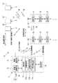
図3は、路側通信機2と車載通信機3の内部構成を示すブロック図である。
路側通信機2は、無線通信のためのアンテナ20が接続された無線通信部(送受信部)21と、中央装置4と双方向通信する有線通信部22と、これらの通信制御を行うプロセッサ(CPU:Central Processing Unit)等よりなる制御部23と、制御部23に接続されたROMやRAM等の記憶装置よりなる記憶部24とを備えている。
[Roadside communication device]
FIG. 3 is a block diagram showing the internal configuration of the
The
路側通信機2の記憶部24は、制御部23が実行する通信制御を実現するためのコンピュータプログラムや、各通信機2,3の通信機ID、後述するスロット情報S6等を記憶している。
路側通信機2の制御部23は、上記コンピュータプログラムを実行することで達成される機能部として、無線通信部21の送信タイミングを制御する送信制御部23aと、ローカル時刻の同期を行う際の同期先となる他の路側通信機2(以下、単に同期先ともいう)を特定する同期先特定部23bと、前記同期先からの送信信号に含まれる時刻情報に基づいて自機のローカル時刻を補正する時刻補正部23cとを備えている。
The
The
送信制御部23aは、自機に割り当てられたスロット番号iの第一スロットSL1(図2)内において、所定の送信時間だけ無線送信を行う。記憶部24は、例えば、以下のa)及びb)に関する情報を含むスロット情報S6を記憶している。このスロット情報S6は路側通信機2ごとに個別に設定されている。
a)自機に割り当てられている第一スロットSL1のスロット番号i
b)無線フレーム、又は自機に割り当てられている第一スロットSL1のスロット番号iの開始時刻、及び送信時間
The
a) Slot number i of the first slot SL1 assigned to the own device
b) The start time and transmission time of the slot number i of the first slot SL1 assigned to the radio frame or the own device
路側通信機2の制御部23は、自機の動作クロックによってローカル時刻をカウントする機能を有しており、送信制御部23aは、自機でカウントしたローカル時刻を基準として、上記スロット情報S6に含まれる無線フレームの開始時刻に合わせて無線送信を行う。
また、送信制御部23aは、路側通信機2間の同期に用いられる時刻情報としてのタイムスタンプTsを送信信号に含めて送信する機能を有している。
このタイムスタンプTsは、自機のローカル時刻における現在の時刻値に対して補正を加えた時刻値を示している。
The
Further, the
This time stamp Ts indicates a time value obtained by correcting the current time value in the local time of the own device.
時刻補正部23cは、自機のローカル時刻における現在時刻値に対して補正を加えて上記タイムスタンプTsを生成する機能を有している。さらに、送信制御部23aは、他の路側通信機2からの送信信号を受信して取得したタイムスタンプTsを補正して補正時刻値Taを求める機能を有している。
路側通信機2は、時刻補正部23cが生成するタイムスタンプTsを他の路側通信機2又は車載通信機3に送信することで、他の通信機のローカル時刻を補正させ、エア同期を行う。
The
The
また、路側通信機2の制御部23は、有線通信部22が受信した中央装置4からの交通情報S2等を、いったん記憶部24に一時的に記憶させ、無線通信部21を介してブロードキャスト送信する機能を有している。
また、制御部23は、無線通信部21が受信した車両情報S3を、いったん記憶部24に一時的に記憶させ、有線通信部22を介して中央装置4に転送するとともに、無線通信部21を介してブロードキャスト送信する機能も有している。
Further, the
In addition, the
車載通信機3は、路側通信機2から上記スロット情報S6を受信すると、スロット情報S6に記された路側通信機2専用のタイムスロット(図2の第1スロットSL1)以外の時間帯(図2の第2スロットSL2)を利用して、キャリアセンス方式による無線送信を行う。
Upon receiving the slot information S6 from the
〔車載通信機〕
車載通信機3は、無線通信のためのアンテナ30に接続された通信部(送受信部)31と、この通信部31に対する通信制御を行うプロセッサ等よりなる制御部32と、この制御部32に接続されたROMやRAM等の記憶装置よりなる記憶部33とを備えている。
記憶部33は、制御部32が実行する通信制御のためのコンピュータプログラムや、各通信装置2,3の通信機ID等を記憶している。
[In-vehicle communication device]
The in-
The
車載通信機3の制御部32は、車車間通信のためのキャリアセンス方式による無線通信を通信部31に行わせるものであり、路側通信機2のような時分割多重方式での通信制御機能は有していない。
従って、車載通信機3の通信部31は、所定の搬送波周波数の受信レベルを常時感知しており、その値がある閾値以上である場合は無線送信を行わず、当該閾値未満になった場合にのみ無線送信を行うようになっている。
The
Accordingly, the communication unit 31 of the in-
また、車載通信機3の制御部32は、車両5(車載通信機3)の現時の位置、方向及び速度等を含む車両情報S3を、通信部31を介して外部にブロードキャストで無線送信する。
さらに、制御部32は、路側通信機2からの送信信号に含まれるタイムスタンプTsを取得することで、自機のローカル時刻を補正し、路側通信機2のローカル時刻に同期するエア同期の機能も有している。
In addition, the
Further, the
また、制御部32は、路側通信機2から送信される、交通情報S2、及び車両情報S3を受信するとともに、他の車両5(車載通信機3)から送信される車両情報S3を受信し、これら各情報に基づいて、右直衝突や出合い頭衝突等を回避する安全運転支援制御を行う機能も有している。
The
〔エア同期について〕
上記のように、本実施形態の無線通信システムでは、路側通信機2が生成するタイムスタンプTsを取得した各通信機2,3が当該タイムスタンプTsを用いてローカル時刻を補正し、路路間及び路車間におけるエア同期を行う。
タイムスタンプTsは、上述のように、路側通信機2の時刻補正部23cによって生成され、自機が送信する送信信号に含めて送信される。
[About air synchronization]
As described above, in the wireless communication system according to the present embodiment, each
As described above, the time stamp Ts is generated by the
タイムスタンプTsは、以下のように生成される。すなわち、路側通信機2の時刻補正部23cは、タイムスタンプTsの送信を決定しそのときの現在時刻値を取得すると、当該現在時刻値に対して、タイムスタンプTsを送信するためのデジタル処理及びアナログ処理等に必要な処理時間(送信までの遅延時間)を加算することで、現在時刻値を補正した時刻値を求め、この時刻値をタイムスタンプTsとして生成する。生成されたタイムスタンプTsは、送信制御部23aによって送信信号に含められて随時送信される。
The time stamp Ts is generated as follows. That is, when the
次に、路側通信機2が行うエア同期の処理について説明する。
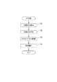
図4は、路側通信機2が行うエア同期の処理を示すフローチャートである。なお、車載通信機3も図4と同様の処理手順によってエア同期を行う。
図4に示すように、エア同期を行う路側通信機2は、まず、自機のローカル時刻を一致させる対象となる同期先となりうる路側通信機2を検索する(ステップS1)。路側通信機2の制御部23は、自機以外の他の路側通信機2からの送信信号を受信し、自機の近傍に位置する他の路側通信機2を検索する。制御部23は、検索した他の路側通信機2からの送信信号のSINR等の受信品質を求める。
制御部23は、上記検索を例えば、数無線フレーム分の期間、繰り返し行う。これにより、制御部23は、検索した他の路側通信機2の送信信号の平均的な受信品質を求めることができる。
Next, the process of air synchronization performed by the
FIG. 4 is a flowchart showing air synchronization processing performed by the
As shown in FIG. 4, the
The
次いで、制御部23の同期先特定部23bは、検索した他の路側通信機2の中から、同期先とする他の路側通信機2を特定する(ステップS2)。制御部23は、検索した他の路側通信機2の中から、送信信号の受信品質が最も良好である路側通信機2を特定する。
上記のように、同期先特定部23bは、他の路側通信機2の送信信号の受信品質に基づいて同期先を特定するので、より通信状態の良好な路側通信機2を同期先として特定でき、より確実にエア同期を行うことができる。
Next, the synchronization
As described above, since the synchronization
同期先とする他の路側通信機2を特定すると、制御部23は、その同期先の他の路側通信機2から送信される送信信号に含まれるタイムスタンプTsを取得する(ステップS3)。
タイムスタンプTsを取得すると、制御部23の時刻補正部23cは、このタイムスタンプTsを用いて、同期のために自機のローカル時刻を補正する(ステップS4)。
制御部23の時刻補正部23cは、同期先からの送信信号を受信してからその送信信号に含まれるタイムスタンプTsを取得するためのアナログ処理及びデジタル処理等に必要な処理時間(タイムスタンプTsを取得するまでの遅延時間)を、タイムスタンプTsにより示される時刻値に加算することで補正し、補正時刻値Taを生成する。
そして、時刻補正部23cは、ステップS3においてタイムスタンプTsを取得したタイミングが補正時刻値Taで表される時刻値となるように、自機のローカル時刻を補正する。
When the other
When the time stamp Ts is acquired, the
The
Then, the
なお、図4では、同期先特定部23bが、複数の他の路側通信機2の中から同期先となる他の路側通信機2を検索、特定する場合を示したが、同期先となる他の路側通信機2は、予め設定されている場合がある。この場合、制御部23による同期先の検索(図4中のステップS1)は行われず、同期先特定部23bは、予め設定された同期先となる他の路側通信機2を特定する。
4 shows a case where the synchronization
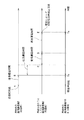
図5は、タイムスタンプTsの送受信において生じるイベントを示すタイムチャートである。図5に示すように、同期先の路側通信機2と(以下、送信側ともいう)、同期を行おうとしている路側通信機2(以下、受信側ともいう)との間で、タイムスタンプTsが送受信される間のイベントには、次のものが含まれる。
FIG. 5 is a time chart showing events that occur in transmission / reception of the time stamp Ts. As shown in FIG. 5, a time stamp Ts between a
1) 送信側が現在時刻値を取得しこれを補正したタイムスタンプTsを生成する時点A
2) 送信側が電波送信する時点B
3) 受信側が電波受信する時点C
4) 受信側の制御部23aにプリアンブルが到達する時点D
5) 受信側の制御部23aがタイムスタンプTsを取得する時点E
1) Time A when the transmitting side acquires the current time value and generates a time stamp Ts obtained by correcting the current time value
2) Time B when the transmitter transmits radio waves
3) Time point C when the receiving side receives radio waves
4) Time point D when the preamble reaches the
5) Time point E when the receiving-
このうち、時点Aでは、上述のように、送信側の路側通信機2は、この時点Aでの現在時刻値を取得しこれを補正したタイムスタンプTsを生成する。
時点Aから時点Bまでの「送信遅延時間」は、送信側の制御部23によるデジタル信号処理や、無線通信部21におけるアナログフィルタの遅延等により生じるものであり、送信側において、回路特性をもとにした計算や事前に測定を行うことによって予測可能である。この時間は、例えば実機では5μ秒程度である。
送信側の路側通信機2は、時点Aの現在時刻値に「送信遅延時間」を加算することで、現在時刻値を補正したタイムスタンプTsを生成する。
Among these, at the time point A, as described above, the transmission-side
The “transmission delay time” from the time point A to the time point B is caused by digital signal processing by the
The
時点Bから時点Cまでの「伝送遅延時間」は、送受信側双方間の距離に依存するため、送受信いずれの側でも単独では予測できないが、その距離が判明すれば演算可能である。
従って、送信側の路側通信機2の座標等の位置情報を、タイムスタンプTsに付加して送信すれば、受信側において、送信側の位置と受信側の位置までの距離に基づいて、伝送遅延時間を算出することができる。
The “transmission delay time” from the time point B to the time point C depends on the distance between the transmission and reception sides, and therefore cannot be predicted independently on either side of transmission and reception, but can be calculated if the distance is known.
Accordingly, if position information such as coordinates of the
なお、この伝送遅延時間は、300m毎に約1μ秒増加するので、例えばITSでの通信距離を600mとすると、最大で2μ秒程度になる。
また、路側通信機2の位置を特定する情報としては、上記座標のような位置を直接特定するものだけでなく、例えば路側通信機2の通信機IDのような識別情報であってもよい。この場合、受信側において、その通信機IDと対応する位置情報を記憶しておけば、当該通信機IDから送信側の位置を求めることができる。
Since this transmission delay time increases by about 1 μsec every 300 m, for example, when the communication distance in ITS is 600 m, it becomes about 2 μsec at the maximum.
Further, the information specifying the position of the
時刻Cから時刻Dまでの「受信遅延時間」は、受信側の無線通信部21におけるアナログフィルタの遅延や、制御部23におけるデジタル信号処理等により生じるものであり、受信側において、回路特性をもとにした計算や事前に測定を行うことによって予測可能である。また、この時間は例えば実機では5μ秒である。
The “reception delay time” from time C to time D is caused by analog filter delay in the
時刻Dから時刻Eまでの「再生遅延時間」は、受信側における、制御部23へのプリアンブルの到達時からタイムスタンプTsの取得時までに要する時間である。この時間は、タイムスタンプTsを通信フレームのどの部分に格納するかと、通信速度によって変動する。
The “playback delay time” from time D to time E is the time required from the time when the preamble arrives at the
図6は、路側通信機2が送信する送信信号のフレームフォーマットの一例を示す図である。図6では、IEEE802.11に準拠したフレームフォーマットを示している。
このフレームフォーマットでは、プリアンブルとシグナルの再生時間はそれぞれ固定長である。よって、ヘッダの先頭から、データ領域の時刻情報(タイムスタンプTs)が格納されている部分までの時間t1を求めれば、上記「再生遅延時間」を求めることができる。
FIG. 6 is a diagram illustrating an example of a frame format of a transmission signal transmitted by the
In this frame format, the playback time of the preamble and the signal is fixed. Therefore, if the time t1 from the beginning of the header to the portion where the time information (time stamp Ts) of the data area is stored is obtained, the “reproduction delay time” can be obtained.
図5に戻って、受信側である同期を行おうとしている路側通信機2の制御部23は、送信側にて時点Aにおける現在時刻値(同期先の路側通信機2の時点Aでの時刻)に「送信遅延時間」を加えて補正した時刻値を示すタイムスタンプTsを時点Eにて取得する。そして、受信側では、「伝送遅延時間」、「受信遅延時間」、及び「再生遅延時間」を求めることができ、タイムスタンプTsが示す時刻値にこれらを加えることで、補正時刻値Taを求めることができる。
この補正時刻値Taは、同期先の路側通信機2の時点Aのローカル時刻(現在時刻値)に基づいて補正した時刻値である。また、同期を行おうとしている路側通信機2は、この補正時刻値Taに対応する時点Eのタイミングを把握できるので、当該路側通信機2の時刻補正部23cは、時点Eが補正時刻値Taとなるように、自機のローカル時刻を補正することで、同期先の路側通信機2のローカル時刻とほぼ一致させることができる。
Returning to FIG. 5, the
The corrected time value Ta is a time value corrected based on the local time (current time value) at the time A of the synchronization destination
以上のようにして、路側通信機2は、タイムスタンプTsを用いて、自機のローカル時刻を補正することで、同期先の路側通信機2に対して相互の時刻ずれを解消することができ、同期を行うことができる。
As described above, the
〔二つの路側通信機2間で相互にエア同期を行う場合について〕
上記図4では、路側通信機2が、同期先となる他の路側通信機2を特定して同期を行う一般的な処理の態様を示したが、本実施形態の無線通信システムでは、各路側通信機2が自律的に同期先を特定するため、二つの路側通信機2間で互いを同期先として特定し、同期を行う場合がある。
[When performing air synchronization between two roadside communication devices 2]
In FIG. 4, the
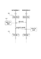
図7は、二つの路側通信機2間で相互にエア同期を行う場合のエア同期の処理を示すシーケンス図である。
図7で示す、路側通信機2A,2Bは、それぞれ互いに隣接して設置されており、第一スロットSLの割り当てが、図2中の路側通信機2A,2Bと同様に設定されている。つまり、路側通信機2Aにはスロット番号2、路側通信機2Bにはスロット番号1の第一スロットSL1が割り当てられている。
図7及び図2に示すように、路側通信機2A,2Bは、無線フレーム長さを一周期として、周期的に送信信号の送信を交互に行う。よって、路側通信機2A,2Bによる送信信号の送信においては、送信信号を送信してから次の送信信号を送信するまでの間に、送信インターバルIが設けられる。
FIG. 7 is a sequence diagram showing an air synchronization process when air synchronization is performed between two
The roadside communication devices 2A and 2B shown in FIG. 7 are installed adjacent to each other, and the assignment of the first slot SL is set similarly to the roadside communication devices 2A and 2B in FIG. That is, the
As shown in FIGS. 7 and 2, the
図7において、まず両路側通信機2A,2Bは、タイムスタンプTsを含む送信信号を送信するとともに(ステップS11,S13)、互いの送信信号及び両路側通信機2A,2B以外の路側通信機2の送信信号を受信することで(ステップS12,S14)、同期先の検索を行う。
図7では、両路側通信機2A,2Bは、同期先の検索の結果、互いを同期先に特定する(ステップS15,S16)。
In FIG. 7, first, the roadside communication devices 2A and 2B transmit a transmission signal including the time stamp Ts (steps S11 and S13), and the
In FIG. 7, both roadside communication devices 2A and 2B specify each other as the synchronization destination as a result of the search for the synchronization destination (steps S15 and S16).
両路側通信機2A,2Bが同期先を特定した後、路側通信機2Bは、送信信号を路側通信機2Aに向けて送信する(ステップS17)。
これを受信した路側通信機2Aは(ステップS18)、当該送信信号に含まれるタイムスタンプTsを取得し、時刻補正を行う(ステップS19)。
次いで、路側通信機2Aは、補正後の時刻に基づいてタイムスタンプTsを生成し、このタイムスタンプTsを送信信号に含めて送信信号を送信する(ステップS20)。
After both the roadside communication devices 2A and 2B specify the synchronization destination, the roadside communication device 2B transmits a transmission signal to the roadside communication device 2A (step S17).
Receiving this (step S18), the roadside communication device 2A acquires the time stamp Ts included in the transmission signal and corrects the time (step S19).
Next, the roadside communication device 2A generates a time stamp Ts based on the corrected time, and transmits the transmission signal by including the time stamp Ts in the transmission signal (step S20).
つまり、路側通信機2Aの時刻補正部23cは、ステップS13においてタイムスタンプTsを含む送信信号を送信してから次に送信信号を送信するステップS20までの送信インターバルIの間に、同期先である路側通信機2BからタイムスタンプTsを含む送信信号を受信すると(ステップS18)、この送信インターバルIの間に、取得したタイムスタンプTsに基づく自機の時刻補正を行っている(ステップS19)。
さらに、路側通信機2Aの送信制御部23aは、送信インターバルIの直後に送信する送信信号には、先の送信インターバルIの間に補正した補正後の時刻に基づくタイムスタンプTsを含めて送信する(ステップS20)。
That is, the
Further, the
ここで、路側通信機2Aには、スロット番号2の第一スロットSL1が割り当てられており、路側通信機2Bには、スロット番号1の第一スロット1が割り当てられているので、送信インターバルIの間に補正を行う路側通信機2Aの時刻補正部23cは、図8に示すように、路側通信機2Bからの送信信号を受信した後(ステップS18)、自機が送信信号を送信するまでの間に(ステップS20)、同期先の時刻情報に基づいて自機の時刻補正を行う必要がある。
Here, the first slot SL1 with
これに対して、本実施形態の無線通信システムでは、無線フレーム中に第一スロットSL1と、第2スロットSL2とを時間軸方向に交互に配置しているので、互いに隣接する第一スロットSL1それぞれの間には、車載通信機3用の第二スロットSL2が設定されている。
On the other hand, in the radio communication system of the present embodiment, the first slot SL1 and the second slot SL2 are alternately arranged in the time axis direction in the radio frame. Between, the second slot SL2 for the in-
仮に、第一スロットSL1それぞれの間に第二スロットSL2が配置されていない場合には、路側通信機2Aは、送信インターバルIに属する期間である、路側通信機2Bからの送信信号に含まれるタイムスタンプTsを受信してから送信を開始するまでの間に時刻補正を行わなければならないため、路側通信機2Bに割り当てられているスロット番号1の第一スロットSL1の間に時刻補正を行わなければならない。
If the second slot SL2 is not disposed between each of the first slots SL1, the roadside communication device 2A is a time period included in the transmission interval I and included in the transmission signal from the roadside communication device 2B. Since time correction must be performed after the stamp Ts is received until transmission is started, time correction must be performed between the first slot SL1 of
これに対して、本実施形態の路側通信機2Aは、スロット番号1の第一スロットSL1において路側通信機2Bからの送信信号を受信した後、自機がスロット番号2の第一スロットSL1にて送信信号を送信するまでの間に、少なくとも第二スロットSL2が介在するので、同期先からの送信信号を受信した後、自機が送信信号を送信するまでの間に、同期先のタイムスタンプTsに基づいて自機の時刻を補正するための期間を十分に確保することができる。
On the other hand, the roadside communication device 2A of the present embodiment receives the transmission signal from the roadside communication device 2B in the first slot SL1 of the
図7に戻って、ステップS20において送信された送信信号を受信した路側通信機2Bは(ステップS21)、当該送信信号に含まれるタイムスタンプTsを取得し、時刻補正を行う(ステップS22)。
次いで、路側通信機2Bは、補正後の時刻に基づいてタイムスタンプTsを生成し、このタイムスタンプTsを送信信号に含めて送信信号を送信する(ステップS23)。
Returning to FIG. 7, the roadside communication device 2B that has received the transmission signal transmitted in step S20 (step S21) acquires the time stamp Ts included in the transmission signal, and corrects the time (step S22).
Next, the roadside communication device 2B generates a time stamp Ts based on the corrected time, and transmits the transmission signal by including the time stamp Ts in the transmission signal (step S23).
〔効果について〕
上記構成の無線通信システムによれば、路側通信機2が、送信インターバルIの間に、同期先からタイムスタンプTsを含む送信信号を受信すると、そのタイムスタンプTsに基づいて自機の時刻の補正を行う時刻補正部23cと、送信インターバルIの直後に送信する送信信号には、当該送信インターバルIの間に補正した補正後の時刻に基づくタイムスタンプTsを含めて送信する送信制御部23aとを備えているので、仮に、二つの路側通信機2が互いを同期先として特定した場合であっても、一の路側通信機2が取得する同期先である他の路側通信機2からのタイムスタンプTsは、他の路側通信機2からの送信信号を受信する前に一の路側通信機2が送信したタイムスタンプTsに基づいて補正されている。このため、一の路側通信機2は、他の路側通信機2の補正後の時刻に基づいて自機の時刻を補正することができ、両方の路側通信機2が、互いの補正前のタイムスタンプTsに基づいて自機の時刻を補正することで、相互間の時刻ずれを解消することができなくなるといった事態を回避することができる。この結果、複数の路側通信機2の間で相互に同期を行ったとしても、確実に相互の時刻ずれを解消することができる。
[Effect]
According to the wireless communication system having the above configuration, when the
〔その他の変形例〕
なお、本発明は、上記各実施形態に限定されることはない。上記実施形態では、路側通信機2Aにスロット番号2の第一スロットSL1、路側通信機2Bにスロット番号1の第一スロットSL1が割り当てられている場合、つまり、二つの路側通信機2にそれぞれ割り当てられている第一スロットSL1が隣接している場合を例示したが、よりスロット番号が離れている第一スロットSL1が割り当てられていても、上記同様の手順でエア同期を行うことができ、確実に相互の時刻ずれを解消することができる。
[Other variations]
The present invention is not limited to the above embodiments. In the above embodiment, when the first slot SL1 with
また、上記実施形態では、無線フレームには、第一スロットSL1が10個配置されている場合を例示したがこれに限定されるものではなく、より多数の第一スロットSL1を配置した場合や、より少なく配置した場合においても上記作用効果を得ることができる。 Further, in the above-described embodiment, the case where ten first slots SL1 are arranged in the radio frame is exemplified, but the present invention is not limited to this, and when a larger number of first slots SL1 are arranged, The above-described effects can be obtained even when the number is less.
なお、今回開示された実施の形態はすべての点で例示であって制限的なものではないと考えられるべきである。本発明の範囲は特許請求の範囲によって示され、特許請求の範囲と均等の意味及び範囲内での全ての変更が含まれることが意図される。 The embodiment disclosed this time should be considered as illustrative in all points and not restrictive. The scope of the present invention is defined by the terms of the claims, and is intended to include any modifications within the scope and meaning equivalent to the terms of the claims.
2 路側通信機
3 車載通信機
23 制御部
23a 送信制御部(送信部)
23b 同期先特定部
23c 時刻補正部
SL1 第一スロット(送信用タイムスロット)
SL2 第二スロット(移動通信機用タイムスロット)
2
23b Synchronization
SL2 second slot (time slot for mobile communication equipment)
Claims (5)
前記路側通信機は、
同期先となる他の路側通信機を特定する同期先特定部と、
前記同期先となる他の路側通信機からの送信信号に含まれる前記時刻情報に基づいて、自機の時刻を補正する補正部と、
自機の時刻に基づいた前記時刻情報を含む送信信号を、自機に割り当てられた前記送信タイムスロットを用いて送信する送信部と、を備えており、
前記補正部は、前記送信部が前記時刻情報を含む前記送信信号を送信してから次に前記時刻情報を含む送信信号を送信するまでの送信インターバルの間に、前記同期先となる他の路側通信機から前記時刻情報を含む送信信号を受信すると、当該送信インターバルの間に、受信した前記時刻情報に基づく、自機の時刻の補正を行い、
前記送信部は、前記送信インターバル直後に送信する送信信号には、当該送信インターバルの間に補正した補正後の時刻に基づく前記時刻情報を含めて送信することを特徴とする無線通信システム。 A plurality of transmission time slots set by time division are allocated to each of a plurality of roadside communication devices, and the roadside communication device transmits time information used for synchronization between the roadside communication devices in a transmission signal. A wireless communication system,
The roadside communication device is
A synchronization destination identifying unit that identifies other roadside communication devices to be synchronized;
Based on the time information included in the transmission signal from the other roadside communication device that is the synchronization destination, a correction unit that corrects the time of the own device,
A transmission unit that transmits the transmission signal including the time information based on the time of the own device using the transmission time slot assigned to the own device, and
The correction unit is another roadside that becomes the synchronization destination during a transmission interval from when the transmission unit transmits the transmission signal including the time information to the next transmission of the transmission signal including the time information. When a transmission signal including the time information is received from a communication device, during the transmission interval, the time of the own device is corrected based on the received time information,
The wireless communication system, wherein the transmission unit transmits the transmission signal transmitted immediately after the transmission interval including the time information based on the corrected time corrected during the transmission interval.
同期先となる他の路側通信機を特定する同期先特定部と、
前記同期先となる他の路側通信機からの送信信号に含まれる前記時刻情報に基づいて、自機の時刻を補正する補正部と、
自機の時刻に基づいた前記時刻情報を含む送信信号を、自機に割り当てられた前記送信タイムスロットを用いて送信する送信部と、を備えており、
前記補正部は、前記送信部が前記時刻情報を含む前記送信信号を送信してから次に前記時刻情報を含む送信信号を送信するまでの送信インターバルの間に、前記同期先となる他の路側通信機から前記時刻情報を含む送信信号を受信すると、当該送信インターバルの間に、受信した前記時刻情報に基づく、自機の時刻の補正を行い、
前記送信部は、前記送信インターバル直後に送信する送信信号には、当該送信インターバルの間に補正した補正後の時刻に基づく前記時刻情報を含めて送信することを特徴とする路側通信機。 A plurality of transmission time slots set by time division are allocated, and a roadside communication device that transmits time information used for synchronization in a transmission signal,
A synchronization destination identifying unit that identifies other roadside communication devices to be synchronized;
Based on the time information included in the transmission signal from the other roadside communication device that is the synchronization destination, a correction unit that corrects the time of the own device,
A transmission unit that transmits the transmission signal including the time information based on the time of the own device using the transmission time slot assigned to the own device, and
The correction unit is another roadside that becomes the synchronization destination during a transmission interval from when the transmission unit transmits the transmission signal including the time information to the next transmission of the transmission signal including the time information. When a transmission signal including the time information is received from a communication device, during the transmission interval, the time of the own device is corrected based on the received time information,
The transmission unit transmits the transmission signal transmitted immediately after the transmission interval including the time information based on the corrected time corrected during the transmission interval.
同期先となる他の路側通信機を特定する同期先特定ステップと、
前記同期先となる他の路側通信機からの送信信号に含まれる前記時刻情報に基づいて、時刻を補正する補正ステップと、
自機の時刻に基づいた前記時刻情報を含む送信信号を、自機に割り当てられた前記送信タイムスロットを用いて送信する送信ステップと、を備え、
前記補正ステップは、前記送信ステップによって前記時刻情報を含む前記送信信号を送信してから次に前記時刻情報を含む送信信号を送信する次の送信ステップまでの送信インターバルの間に、前記同期先となる他の路側通信機から前記時刻情報を含む送信信号を受信すると、当該送信インターバルの間に、受信した前記時刻情報に基づく、自機の時刻の補正を行うものであり、
前記送信ステップは、前記送信インターバル直後に送信する送信信号には、当該送信インターバルの間に補正した補正後の時刻に基づく前記時刻情報を含めて送信することを特徴とする同期方法。 A plurality of transmission time slots set by time division are allocated to each of a plurality of roadside communication devices, and the roadside communication device transmits time information used for synchronization between the roadside communication devices in a transmission signal. A wireless communication system synchronization method comprising:
A synchronization destination specifying step for specifying another roadside communication device as a synchronization destination;
A correction step for correcting the time based on the time information included in the transmission signal from the other roadside communication device that is the synchronization destination;
A transmission step of transmitting a transmission signal including the time information based on the time of the own device using the transmission time slot assigned to the own device, and
The correction step includes transmitting the transmission signal including the time information in the transmission step to a next transmission step of transmitting a transmission signal including the time information to a next transmission step. When the transmission signal including the time information is received from the other roadside communication device, the time of the own device is corrected based on the received time information during the transmission interval.
In the transmission method, the transmission signal transmitted immediately after the transmission interval includes the time information based on the corrected time corrected during the transmission interval.
Priority Applications (1)
| Application Number | Priority Date | Filing Date | Title |
|---|---|---|---|
| JP2011123492A JP2012253501A (en) | 2011-06-01 | 2011-06-01 | Radio communication system, road-side communication equipment therefor, and synchronization method |
Applications Claiming Priority (1)
| Application Number | Priority Date | Filing Date | Title |
|---|---|---|---|
| JP2011123492A JP2012253501A (en) | 2011-06-01 | 2011-06-01 | Radio communication system, road-side communication equipment therefor, and synchronization method |
Publications (1)
| Publication Number | Publication Date |
|---|---|
| JP2012253501A true JP2012253501A (en) | 2012-12-20 |
Family
ID=47525916
Family Applications (1)
| Application Number | Title | Priority Date | Filing Date |
|---|---|---|---|
| JP2011123492A Pending JP2012253501A (en) | 2011-06-01 | 2011-06-01 | Radio communication system, road-side communication equipment therefor, and synchronization method |
Country Status (1)
| Country | Link |
|---|---|
| JP (1) | JP2012253501A (en) |
Cited By (1)
| Publication number | Priority date | Publication date | Assignee | Title |
|---|---|---|---|---|
| US11097342B2 (en) | 2014-12-12 | 2021-08-24 | Sumitomo Electric Sintered Alloy, Ltd. | Method for manufacturing sintered component and sintered component |
Citations (3)
| Publication number | Priority date | Publication date | Assignee | Title |
|---|---|---|---|---|
| WO2008111606A1 (en) * | 2007-03-13 | 2008-09-18 | Sharp Kabushiki Kaisha | Mobile communication system, mobile station device, base station device, and mobile communication method |
| JP2010021870A (en) * | 2008-07-11 | 2010-01-28 | Denso Corp | Wireless communication system and communication apparatus |
| JP2010170243A (en) * | 2009-01-21 | 2010-08-05 | Sumitomo Electric Ind Ltd | Roadside communication equipment |
-
2011
- 2011-06-01 JP JP2011123492A patent/JP2012253501A/en active Pending
Patent Citations (3)
| Publication number | Priority date | Publication date | Assignee | Title |
|---|---|---|---|---|
| WO2008111606A1 (en) * | 2007-03-13 | 2008-09-18 | Sharp Kabushiki Kaisha | Mobile communication system, mobile station device, base station device, and mobile communication method |
| JP2010021870A (en) * | 2008-07-11 | 2010-01-28 | Denso Corp | Wireless communication system and communication apparatus |
| JP2010170243A (en) * | 2009-01-21 | 2010-08-05 | Sumitomo Electric Ind Ltd | Roadside communication equipment |
Cited By (2)
| Publication number | Priority date | Publication date | Assignee | Title |
|---|---|---|---|---|
| US11097342B2 (en) | 2014-12-12 | 2021-08-24 | Sumitomo Electric Sintered Alloy, Ltd. | Method for manufacturing sintered component and sintered component |
| US11219950B2 (en) * | 2014-12-12 | 2022-01-11 | Sumitomo Electric Sintered Alloy, Ltd. | Sintered component |
Similar Documents
| Publication | Publication Date | Title |
|---|---|---|
| US11215993B2 (en) | Method and device for data sharing using MEC server in autonomous driving system | |
| JP2014023090A (en) | Receiver and radio communication system | |
| US20200029191A1 (en) | Method and apparatus for setting a server bridge in an autonomous driving system | |
| JP2014127993A (en) | Communication system, communication apparatus, computer program, synchronization processing device, and synchronization method | |
| JP2013258467A (en) | Road side communication device and communication system | |
| JP5115577B2 (en) | Wireless communication system and time correction method thereof | |
| JP2012253498A (en) | Radio transmitter, and transmission control method and transmission control program therefor | |
| JP5983212B2 (en) | Wireless device, computer program, synchronization processing device, and synchronization correction method | |
| JP5239889B2 (en) | Roadside communication device, computer program, and transmission timing synchronization method | |
| JP2010171509A (en) | Roadside communication apparatus | |
| JP5527375B2 (en) | Wireless communication system and time correction method thereof | |
| JP2010171575A (en) | Time slot allocation device | |
| JP2012253501A (en) | Radio communication system, road-side communication equipment therefor, and synchronization method | |
| JP6938721B2 (en) | Wireless communication systems, roadside communicators, packet transmission methods, and computer programs | |
| JP5954454B2 (en) | Wireless communication system and time correction method thereof | |
| JP5343909B2 (en) | RADIO COMMUNICATION SYSTEM, MOBILE COMMUNICATION DEVICE USED FOR THE SAME, AND TRANSMISSION CONTROL METHOD | |
| JP5088392B2 (en) | Wireless communication system, roadside communication device used therefor, and time slot allocation method | |
| JP5488174B2 (en) | Radio, radio communication system, and communication control method | |
| JP6563863B2 (en) | Receiving machine | |
| JP6512343B2 (en) | Wireless communication system and mobile communication device and transmission control method used therefor | |
| JP2011209867A (en) | Road side communication equipment and transmission power adjustment method | |
| JP5708836B2 (en) | Transmitter used in wireless communication system and time stamp transmission method | |
| JP2010199937A (en) | Communication controlling apparatus, roadside communication device with the same, and slot allocation method | |
| JP2019126084A (en) | Radio communication system, and mobile communication device and transmission control method used in the same | |
| JP2014132470A (en) | On-vehicle communication device and road side communication device |
Legal Events
| Date | Code | Title | Description |
|---|---|---|---|
| A621 | Written request for application examination |
Free format text: JAPANESE INTERMEDIATE CODE: A621 Effective date: 20140128 |
|
| A977 | Report on retrieval |
Free format text: JAPANESE INTERMEDIATE CODE: A971007 Effective date: 20140829 |
|
| A131 | Notification of reasons for refusal |
Free format text: JAPANESE INTERMEDIATE CODE: A131 Effective date: 20140909 |
|
| A521 | Request for written amendment filed |
Free format text: JAPANESE INTERMEDIATE CODE: A523 Effective date: 20141030 |
|
| A02 | Decision of refusal |
Free format text: JAPANESE INTERMEDIATE CODE: A02 Effective date: 20141125 |
|
| A521 | Request for written amendment filed |
Free format text: JAPANESE INTERMEDIATE CODE: A523 Effective date: 20150223 |
|
| A911 | Transfer to examiner for re-examination before appeal (zenchi) |
Free format text: JAPANESE INTERMEDIATE CODE: A911 Effective date: 20150303 |
|
| A912 | Re-examination (zenchi) completed and case transferred to appeal board |
Free format text: JAPANESE INTERMEDIATE CODE: A912 Effective date: 20150327 |