JP2012253496A - Radio communication system, cell/antenna arrangement pattern optimization device, and program - Google Patents
Radio communication system, cell/antenna arrangement pattern optimization device, and program Download PDFInfo
- Publication number
- JP2012253496A JP2012253496A JP2011123421A JP2011123421A JP2012253496A JP 2012253496 A JP2012253496 A JP 2012253496A JP 2011123421 A JP2011123421 A JP 2011123421A JP 2011123421 A JP2011123421 A JP 2011123421A JP 2012253496 A JP2012253496 A JP 2012253496A
- Authority
- JP
- Japan
- Prior art keywords
- cell
- antennas
- center
- antenna
- pattern
- Prior art date
- Legal status (The legal status is an assumption and is not a legal conclusion. Google has not performed a legal analysis and makes no representation as to the accuracy of the status listed.)
- Granted
Links
Images


Landscapes
- Mobile Radio Communication Systems (AREA)
Abstract
Description
本発明は、無線通信システム及びセル・アンテナ配備パターン最適化装置及びプログラムに係り、特に、移動体通信のセル及びアンテナの配置を最適化するための無線通信システム及びセル・アンテナ配備パターン最適化装置及びプログラムに関する。 The present invention relates to a radio communication system, a cell / antenna deployment pattern optimization apparatus, and a program, and more particularly to a radio communication system and a cell / antenna deployment pattern optimization apparatus for optimizing the arrangement of cells and antennas for mobile communication. And the program.
移動通信において、セル設計(アンテナの配備設計)を行うためのパスロス関数m(d)の第一近似としては、 In mobile communications, the first approximation of the path loss function m (d) for cell design (antenna deployment design)

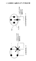
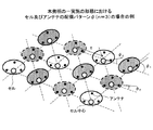
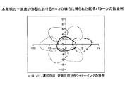
近年、複数のアンテナを用いた無線システムが登場し、特に、1つの基地局が複数の地点に設置されたアンテナを利用して、同一信号を送信、あるいは、受信して、主にエラー性能(誤り率特性)の改善をはかるマクロダイバシティ技術が利用され始めた(図1)。例えば、セクタアンテナを用いたシステムとしては、非特許文献1があり、基地局側が3箇所のアンテナを用いる構成が提案されている。本発明と同じ、全方位アンテナを用いるシステムのセル・アンテナ配備パターンについては、非特許文献2で検討され、図2に示すn=4(nは1つの基地局に配備されるアンテナ地点の数)のパターンが推奨された。
In recent years, a wireless system using a plurality of antennas has appeared, and in particular, one base station transmits or receives the same signal using antennas installed at a plurality of points, and mainly performs error performance ( Macro diversity technology that improves the error rate characteristics) has begun to be used (Fig. 1). For example, as a system using a sector antenna, there is Non-Patent Document 1, and a configuration in which the base station side uses three antennas has been proposed. The cell antenna deployment pattern of a system using an omnidirectional antenna, which is the same as that of the present invention, was examined in Non-Patent
なお、ミクロダイバシティを用いるようなケースでは、1箇所に複数のアンテナの場合がある。そこで、以下の記述では、アンテナは1箇所に設置されたアンテナの意味に用いる。従って、1つのアンテナ、という記述は、実際には、1箇所に設置された複数のアンテナの場合がある。 In the case of using microdiversity, there may be a plurality of antennas in one place. Therefore, in the following description, an antenna is used to mean an antenna installed at one place. Therefore, the description of “one antenna” may actually be a plurality of antennas installed in one place.
また、無線システムにおいては、受信信号電力が非常に重要である。受信信号電力は、送信点からの距離に依存するパスロス関数でモデル化される成分と、遮蔽物等による影響からなるシャドーイングと称される成分と、マルチパス等の影響による瞬時変動成分に、通常、分けて考えることができる。ここで、瞬時変動は、ミクロダイバシティ等の技術により無視できるようになる場合が多いことから、パスロスとシャドーイングが考慮できることが重要である。 In a wireless system, received signal power is very important. The received signal power is divided into a component modeled by a path loss function that depends on the distance from the transmission point, a component called shadowing consisting of the influence of a shielding object, etc., and an instantaneous fluctuation component due to the influence of multipath, etc. Usually, you can think separately. Here, since the instantaneous fluctuation is often negligible by a technique such as microdiversity, it is important that path loss and shadowing can be considered.
パスロスとシャドーイングを考慮した場合、既存の1セル1アンテナのシステムでは、受信信号電力m(d)は、
m(d)=Kl(d)ν
で表される。ここで、dは、送受信間距離、l(d)は、パスロス関数であり、
In consideration of path loss and shadowing, in the existing 1-cell 1-antenna system, the received signal power m (d) is
m (d) = Kl (d) ν
It is represented by Where d is the distance between transmission and reception, l (d) is the path loss function,
上記のように、従来の無線通信システムでは、通信セルを構成する基地局に1つのアンテナのみが備えられていることを前提としてセル配置の設計がなされていた。1つの基地局が複数の地点に全方位アンテナを配備する無線システムでは、最適なセル配置及びアンテナ配置を行うための方法は提供されておらず、セルは円形とはならず、平面を効率的に配備するパターンも知られていない。 As described above, in the conventional wireless communication system, the cell arrangement is designed on the assumption that the base station constituting the communication cell is provided with only one antenna. In a wireless system in which one base station deploys omnidirectional antennas at multiple points, a method for optimal cell placement and antenna placement is not provided, and the cell is not circular and the plane is efficient. There is no known pattern to deploy to.
本発明は、上記の点に鑑みなされたもので、均一の平面に対して、基地局、および、全方位アンテナを効率的に配備するパターンを決定する方法と、その結果得られるアンテナの配備パターンによりセル及びアンテナが配置されることが可能な無線通信システム及びセル・アンテナ配備パターン最適化装置及びプログラムを提供することを目的とする。 The present invention has been made in view of the above points, and a method for determining a pattern for efficiently deploying a base station and an omnidirectional antenna with respect to a uniform plane, and a resulting antenna deployment pattern. It is an object of the present invention to provide a radio communication system, a cell antenna deployment pattern optimization device, and a program in which cells and antennas can be arranged.
特に、基地局系の主たるコスト要因が基地局主装置である場合には、現実的な配備パターンのうち、平面をコスト最小で被覆するパターンを与える。なお、主たるコストが基地局主装置とは言えないような場合についても、「共用アンテナの場合」として言及する。また、本発明では、シャドウイングが考慮されていないが、アンテナ数が同じである場合には、シャドウイング対策に差がないので、距離減衰項のみに基づくものとした。 In particular, when the main cost factor of the base station system is the base station main apparatus, a pattern that covers the plane at a minimum cost is provided among the realistic deployment patterns. It should be noted that the case where the main cost cannot be said to be the base station main apparatus is also referred to as “shared antenna”. Further, in the present invention, shadowing is not considered, but when the number of antennas is the same, there is no difference in the countermeasures for shadowing, and therefore, it is based only on the distance attenuation term.
上記の課題を解決するため、本発明(請求項1)は、1つの基地局がn箇所の地点に置かれたアンテナを使用する複数の基地局により構成される無線通信システムであって、
前記基地局が、n個のアンテナを備え、かつ、当該基地局により構成される通信エリアであるセルの中心と該n個のアンテナが、
座標軸原点をあるセルの中心から別のセルの中心に移しても、また、座標軸を2π/n(nはアンテナ数)回転しても、同じ配備パターンとなることを拘束条件として、任意地点(x,y)での受信電力mn(d1,…,dn)=Kf(l(d1)ν1,…,l(dn)νn)が、目標値v'を確率1−ε以上で満足し、かつ、全平面を最小のセル数で覆う漸近的最小被覆問題を解くことにより導出された最適なセル配置のパターン及びアンテナの配置パターンにより配置される。
In order to solve the above problems, the present invention (Claim 1) is a wireless communication system including a plurality of base stations using antennas in which one base station is placed at n points.
The base station includes n antennas, and the center of a cell that is a communication area configured by the base station and the n antennas are
Even if the coordinate axis origin is moved from the center of one cell to the center of another cell, and the coordinate axis is rotated by 2π / n (where n is the number of antennas) The received power m n (d 1 ,..., d n ) = Kf (l (d 1 ) ν 1 ,..., l (d n ) ν n ) at x, y) is the probability 1− Arranged by an optimal cell arrangement pattern and antenna arrangement pattern derived by solving an asymptotic minimum covering problem that satisfies the above-mentioned ε and covers the entire plane with the minimum number of cells.
また、本発明(請求項2)は、アンテナ数が2(n=2)の場合は、平面を合同な平行四辺形で分割し、該平行四辺形の各頂点にセルの中心が配備され、
アンテナ数が3(n=3)の場合は、平面を合同な正六角形で分割し、該正六角形の各頂点にセルの中心が配備され、
アンテナ数が4(n=4)の場合は、平面を合同な正方形で分割し、該正方形の各頂点にセルの中心が配備され、
アンテナ数が6(n=6)の場合は、平面を合同な正三角形で分割し、該正三角形の各頂点にセルの中心が配備される。
In the present invention (Claim 2), when the number of antennas is 2 (n = 2), the plane is divided into congruent parallelograms, and the center of the cell is arranged at each vertex of the parallelogram,
When the number of antennas is 3 (n = 3), the plane is divided by a congruent regular hexagon, and the center of the cell is arranged at each vertex of the regular hexagon,
When the number of antennas is 4 (n = 4), the plane is divided into congruent squares, and the center of the cell is arranged at each vertex of the squares.
When the number of antennas is 6 (n = 6), the plane is divided by congruent equilateral triangles, and the center of the cell is arranged at each vertex of the equilateral triangle.
また、本発明(請求項3)は、複数の基地局により構成される無線通信システムにおけるセル配置及びアンテナ配置を最適化するためのセル・アンテナ配備パターン最適化装置であって、
前記最適化装置は、
拘束条件により、任意地点(x,y)での受信電力mn(d1,…,dn)=Kf(l(d1)ν1,…,l(dn)νn)が、目標値v'を確率1-ε以上で満足し、かつ、全平面を最小のセル数で覆う漸近的最小被覆問題を解くことにより、最適なセル配置のパターン及びアンテナの配置パターンを導出する最適化手段を備える。
Further, the present invention (Claim 3) is a cell antenna arrangement pattern optimization device for optimizing cell arrangement and antenna arrangement in a radio communication system composed of a plurality of base stations,
The optimization device includes:
The received power m n (d 1 ,..., D n ) = Kf (l (d 1 ) ν 1 ,..., L (d n ) ν n ) at an arbitrary point (x, y) depends on the constraint condition. Optimization that derives the optimal cell layout pattern and antenna layout pattern by solving the asymptotic minimum coverage problem that satisfies the value v 'with probability 1-ε or more and covers the entire plane with the minimum number of cells Means.
また、本発明(請求項4)は、アンテナ数n、fの関数形、パスロス関数l(d)の関数形およびα等のパラメータ値、正規化目標値v、目標値不達成許容値εを入力する入力手段を有し、
前記最適化手段は、
前記入力手段から取得した値に基づいて、セルの中心を頂点とする多角形の一辺に沿った直線と、セル中心と当該セルのアンテナの1つを結ぶ直線のなす角φ∈Φ(n)と、原点に中心を持つセルの境界
Rn((x,y)|→x1(0,0,φ),…,→xn(0,0,φ))=1−ε
(→はベクトルを示す)
上の任意の(x,y)に対して、
Rn((x,y)|→x1(i,j,Fi,j(φ)),…,→xn(i,j,Fi,j(φ)))≧1−ε
を満たす(i,j)が存在することを拘束条件とし、セルの重なりあいを考慮した有効被覆サイズについて、拘束条件付最適化問題を解くことにより、該有効被覆サイズを該拘束条件の下で最大化し、最適なセル配置のパターン及びアンテナの配置パターンを導出する最適パターン導出手段を含む。
In the present invention (claim 4), the function form of the number of antennas n and f, the function form of the path loss function l (d), the parameter value such as α, the normalized target value v, and the target value non-achievable allowable value ε Having input means to input,
The optimization means includes
Based on the value obtained from the input means, an angle φεΦ (n) formed by a straight line along one side of the polygon having the center of the cell as a vertex and a straight line connecting the cell center and one of the antennas of the cell. And the boundary of the cell centered at the origin
R n ((x, y) | → x 1 (0,0, φ),…, → x n (0,0, φ)) = 1−ε
(→ indicates a vector)
For any (x, y) above,
R n ((x, y) | → x 1 (i, j, F i, j (φ)),…, → x n (i, j, F i, j (φ))) ≧ 1−ε
The constraint condition is that there exists (i, j) that satisfies the above condition, and the effective coverage size is considered under the constraint condition by solving the constrained optimization problem for the effective coverage size considering cell overlap. Optimal pattern deriving means for maximizing and deriving an optimal cell arrangement pattern and antenna arrangement pattern is included.
また、本発明(請求項5)は、前記最適パターン導出手段において、
前記有効被覆サイズs(n)(pn)を、
Further, according to the present invention (Claim 5), in the optimum pattern deriving means,
The effective covering size s (n) (p n ),
で与え、前記pnを調整し、前記有効被覆サイズs(n)(pn)を前記拘束条件の下で、最大化する手段を含む。
And pn is adjusted, and the effective covering size s (n) (p n ) is maximized under the constraint conditions.
また、本発明(請求項6)は、前記基地局が、前記アンテナを複数セルの基地局で共用する場合に、
前記入力手段は、
アンテナコスト、主要部コスト、または、それらの比を、共用するための条件として更に入力する手段を含み、
前記最適化手段は、
前記共用するための条件が付加された拘束条件に基づいて前記最適化問題の解を求め、得られた解によって定められる位置に前記セルの中心が配置され、前記n個のアンテナが、当該セルの中心を中心とする正n角形の各頂点に配置される配置パターンを導出する手段を含む。
Further, the present invention (Claim 6), when the base station shares the antenna with a base station of a plurality of cells,
The input means includes
Means for further inputting the antenna cost, main part cost, or ratio thereof as a condition for sharing;
The optimization means includes
The solution of the optimization problem is obtained based on the constraint condition to which the condition for sharing is added, the center of the cell is arranged at a position determined by the obtained solution, and the n antennas are connected to the cell. Means for deriving an arrangement pattern to be arranged at each vertex of a regular n-gon centering on the center of.
本発明(請求項7)は、コンピュータを、請求項3乃至6記載のいずれか1項に記載のセル・アンテナ配備パターン最適化装置の各手段として機能させるための最適化プログラムである。
The present invention (Claim 7) is an optimization program for causing a computer to function as each means of the cell antenna arrangement pattern optimizing device according to any one of
本発明によれば、座標軸原点をあるセルの中心から別のセルの中心に移しても同様のセル配置のパターンとなり、かつ、座標軸を2π/n(nは1つの基地局の備えるアンテナの本数)回転しても同様のセル位置のパターンとなることを制限して、漸近最小被覆(領域Φが2次元の全平面であるとき)問題を解くことによって、最適なセル位置のパターン及びアンテナの配置のパターンを導出し、当該方法により導出されたパターンに基づいてセル及びアンテナを配置することが可能となる。結果として、
・アンテナが2個の場合:
セルの中心:平面を平行四辺形に区切ったときの各頂点;
アンテナ:当該セルの中心を中点とする直線上の2箇所;
・アンテナが3個の場合:
セルの中心:平面を正六角形に区切ったときの各頂点;
アンテナ:当該セルの中心を中心とする正三角形の各頂点;
・アンテナが4個の場合:
セルの中心:平面を正方形に区切ったときの各頂点;
アンテナ:当該セルの中心を中心とする正方形の各頂点;
・アンテナが6個の場合:
セルの中心:平面を正三角形に区切ったときの頂点;
アンテナ:当該セルの中心を中心とする正六角形の各頂点
となる。このような構成とすることで、最小のセル数で平面をカバーすることが可能となる。
According to the present invention, even if the coordinate axis origin is moved from the center of one cell to the center of another cell, a similar cell arrangement pattern is obtained, and the coordinate axis is 2π / n (n is the number of antennas included in one base station) ) By limiting the asymptotic minimum coverage (when the region Φ is a two-dimensional all-plane) problem by restricting the same cell position pattern from being rotated, the optimal cell position pattern and antenna An arrangement pattern can be derived, and cells and antennas can be arranged based on the pattern derived by the method. as a result,
・ When there are two antennas:
Cell center: each vertex when the plane is divided into parallelograms;
Antenna: Two points on a straight line centered on the center of the cell;
・ When there are three antennas:
Cell center: each vertex when the plane is divided into regular hexagons;
Antenna: each vertex of an equilateral triangle centered on the center of the cell;
・ When there are four antennas:
Cell center: each vertex when the plane is divided into squares;
Antenna: each vertex of a square centered on the center of the cell;
・ When there are 6 antennas:
Cell center: vertex when the plane is divided into equilateral triangles;
Antenna: Each vertex of a regular hexagon centering on the center of the cell. With this configuration, it is possible to cover the plane with the minimum number of cells.
以下図面と共に、本発明の実施の形態を説明する。 Embodiments of the present invention will be described below with reference to the drawings.
図1は、本発明の最適化対象となる無線通信システムの構成を示す。 FIG. 1 shows a configuration of a wireless communication system to be optimized by the present invention.
同図において、アンテナ11〜14は、通常、数キロメートル離れた異なる設置場所に設置される。各アンテナ11〜14は、D/A変換等の簡単な機能を具備したリモートユニット21〜24と、専用線等のリンク31〜34を介して、信号処理等を行う基地局主装置41,42に接続される。図1の場合は、基地局41,42それぞれが2つアンテナを備える構成である。各基地局41,42は、ネットワーク51により相互に接続され、広域なサービスを提供する。端末61の送受信信号が、アンテナ11,12で受送信され、リモートユニット21,22での処理を経て、主装置41で変復調等がなされ、ネットワーク51を経て、通信相手である他の端末、ここでは固定端末71と通信する。
In the figure, antennas 11 to 14 are usually installed at different installation locations several kilometers away. Each of the antennas 11 to 14 includes
図1の無線通信システムは、構成の一例であり、本発明では、1つの基地局がn箇所の地点に置かれたアンテナを使用するものであり、基地局が構成するセルを複数設置して通信サービスを提供する。図1の例では、基地局41,42は、2つのアンテナ(n=2)を備える構成である。このとき、セルの中心は平面を平行四辺形に区切ったときの各頂点であり、アンテナは当該セルの中心を中点とする直線上の2箇所に配置される。また、図1には記載していないが、アンテナが3個の場合は、セルの中心が平面を正六角形に区切ったときの各頂点であり、アンテナは当該セルの中心を中心とする正三角形の各頂点に配置される。また、アンテナが4個の場合は、セルの中心は平面を正方形に区切ったときの各頂点であり、アンテナは当該セルの中心を中心とする正方形の各頂点に配置される。さらに、アンテナが6個の場合は、セルの中心は平面を正三角形に区切ったときの頂点であり、アンテナ:当該セルの中心を中心とする正六角形の各頂点に配置される。
The wireless communication system of FIG. 1 is an example of the configuration. In the present invention, one base station uses an antenna placed at n points, and a plurality of cells that the base station configures are installed. Provide communication services. In the example of FIG. 1, the
以下に、このような配置パターンを決定する処理について説明する。 Hereinafter, a process for determining such an arrangement pattern will be described.
[第1の実施の形態]
本実施の形態では、図1に示す無線通信システムを対象として、当該システムのアンテナ配置のパターン及びセル配置のパターンを決定するセル・アンテナ配備パターン最適化装置について説明する。
[First Embodiment]
In the present embodiment, a cell / antenna deployment pattern optimization apparatus that determines an antenna arrangement pattern and a cell arrangement pattern of the system will be described for the radio communication system shown in FIG.
理想的なマクロダイバシティと均一な平面のもとでは、受信信号電力は、 Under ideal macro diversity and uniform plane, the received signal power is
上式で、εは、目標値不達成許容値、
In the above equation, ε is a target value non-achievable allowable value,
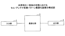
図3は、本発明の第1の実施の形態におけるセル・アンテナ配備パターン最適化装置の構成を示す。 FIG. 3 shows a configuration of the cell antenna arrangement pattern optimization apparatus according to the first embodiment of the present invention.
同図に示す最適化装置は、入力部1、最適化部3、出力部4から構成される。
The optimization apparatus shown in FIG. 1 includes an input unit 1, an
入力部1は、アンテナ数n、fの関数形、パスロス関数l(d)の関数形およびα等のパラメータ値、正規化目標値v、目標値不達成許容値εを最適化部3に入力する。
The input unit 1 inputs the function form of the number of antennas n and f, the function form of the path loss function l (d), the parameter value such as α, the normalized target value v, and the target value unachievable allowable value ε to the
最適化部3は、入力部1から入力された値により、有効被覆サイズを拘束条件のもとで最大化するよう最適化問題を解き、求められたセルおよびアンテナの配備パターンを出力部4に出力する。
The
本発明では、基地局41,42、および、アンテナ11〜14の配備パターンとして、現実的なある集合を想定し、その集合に属するパターンの中で、漸近的最小被覆パターンを与える。
In the present invention, as a deployment pattern of the
まず、領域Φに対する最小被覆とは、最小のセル数で、領域Φ内の任意の点(x, y)に対して、必ず、(x, y)を覆うセルが存在するという条件を満たすものを言う。最小セル数は、実効被覆サイズ(領域Φの面積をセル数で割ったもの)の最大化と等価であることに注意する。さらに、領域Φが2次元の全平面であるとき、漸近的最小被覆という。 First, the minimum coverage for the region Φ is the minimum number of cells and satisfies the condition that there is always a cell covering (x, y) for any point (x, y) in the region Φ. Say. Note that the minimum number of cells is equivalent to maximizing the effective coverage size (area Φ divided by number of cells). Furthermore, when the region Φ is a two-dimensional whole plane, it is called asymptotic minimum coverage.
セルの形状が一般的な場合、漸近的最小被覆問題は解けないので、ここでは、配備パターンを、ある条件を満たすものに限定する。その条件を定義するため、以下のノーテーションを用いる。 Since the asymptotic minimum coverage problem cannot be solved when the cell shape is general, here, the deployment pattern is limited to a certain condition. The following notation is used to define the conditions.
・→cj:第jセル(基地局)の中心位置。 -> C j : Center position of the j-th cell (base station).
・→Tc(x):xのセル中心→c分の平行移動。すなわち、 -> T c (x): x cell center-> c translation. That is,
考慮の対象とする配備パターンの満たすべき条件として、以下を定める。 The following conditions are to be satisfied for the deployment pattern to be considered.
1)第jセルの中心位置→cjに対して、→Mn(cj)もまた、セル中心となること。すなわち、 1) For the center position of the jth cell → c j , → M n (c j ) is also the cell center. That is,
2)第jセルのアンテナ{→x1,j,…, →xn,j}に対して 2) For the antenna {→ x 1, j , ..., → x n, j } of the j th cell
上記条件は、座標軸原点をあるセルの中心から別のセルの中心に移しても、また、座標軸を2π/n回転しても、同じ配備パターンとなることを意味している。結果的に、同一形状セルが周期的に、また、角度2π/nの対称性をもって現れることを意味する。 The above condition means that even if the coordinate axis origin is moved from the center of one cell to the center of another cell, and the coordinate axis is rotated by 2π / n, the same deployment pattern is obtained. As a result, it means that cells having the same shape appear periodically and with symmetry of an angle of 2π / n.
上記条件から、最適化部3で求められるセルおよびアンテナの配備パターンは、以下のようになることが証明できる。
From the above conditions, it can be proved that the cell and antenna deployment patterns obtained by the
・n = 2では、平面を合同な平行四辺形で分割し、その平行四辺形の各頂点にセルの中心がくる。 • For n = 2, the plane is divided into congruent parallelograms, and the center of the cell is at each vertex of the parallelogram.
・n = 3では、平面を合同な正六角形で分割し、その各頂点にセルの中心がくる。 ・ For n = 3, the plane is divided into congruent regular hexagons, and the center of the cell comes to each vertex.
・n = 4では、平面を合同な正方形で分割し、その各頂点にセルの中心がくる。 ・ For n = 4, the plane is divided into congruent squares, and the center of the cell comes to each vertex.
・n = 6では、平面を合同な正三角形で分割し、その各頂点にセルの中心がくる。 ・ For n = 6, the plane is divided by congruent equilateral triangles, and the center of the cell comes to each vertex.
・各セルのアンテナは、セル中心を中心とする合同な正n角形の各頂点に配備される。 The antenna of each cell is deployed at each vertex of a congruent regular n-gon centered on the cell center.
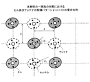
さらに、L1を、n = 2の場合は、上記平行四辺形、n = 3の場合は、上記正六角形、n = 4の場合は、上記正方形、n = 6の場合は、上記正三角形、の一辺に沿った直線、L2をセル中心と当該セルのアンテナの1つを結ぶ直線とし、L1とL2のなす角をφとする。そのとき、「φは、周期的に、4つ(n = 2の場合、図4)、3つ(n = 3の場合、図5)、2つ(n = 4の場合、図6)、の値を周期的にとる」ことも証明できる。 Furthermore, L 1 is the parallelogram when n = 2, the regular hexagon when n = 3, the square when n = 4, the equilateral triangle when n = 6, A line along one side, L 2 is a line connecting the cell center and one of the antennas of the cell, and an angle between L 1 and L 2 is φ. Then, “φ is periodically 4 (in the case of n = 2, FIG. 4), 3 (in the case of n = 3, FIG. 5), 2 (in the case of n = 4, FIG. 6), It can also be proved that the value of is periodically taken.
任意の整数i,jに対して、(x(i,j), y(i,j))をセル中心の位置、→xk(i,j,φ)をセル中心が(x(i,j), y(i,j))にあるセルの第kアンテナ位置、2aをセル内の隣接アンテナ間距離、Φ(n)をφがとり得る値の集合とする。(すなわち、 For any integer i, j, (x (i, j), y (i, j)) is the cell center position, → x k (i, j, φ) is the cell center (x (i, j, Let j), y (i, j)) be the k-th antenna position of the cell, 2a is the distance between adjacent antennas in the cell, and Φ (n) is a set of values that φ can take. (I.e.
すると、漸近最小被覆問題は、次のような拘束条件付最適化問題になる。 Then, the asymptotic minimum covering problem becomes the following optimization problem with constraints.
[拘束条件]
当該拘束条件は入力部1から予め入力され、最適化部3内のメモリ(図示せず)に保持されているものとする。
[Restraint condition]
It is assumed that the constraint condition is input in advance from the input unit 1 and held in a memory (not shown) in the
任意のφ∈Φ(n)と、原点に中心を持つセルの境界 Arbitrary φ∈Φ (n) and cell boundary centered at the origin
[最適化]
以下に、最適化部3における最適化処理について説明する。
[optimisation]
Below, the optimization process in the
有効被覆サイズs(n)(pn)は、入力部1より Effective coverage size s (n) (p n ) is input from input 1
(pnに含まれるパラメータ数が多い場合は、最適化は、数値計算上の重荷となる。この場合は、任意のi,jについて、φi=φjとして上記最適化を実行することが有効である。)
(1) アンテナ数n = 2の場合:
任意の整数i,jを用いて、セル中心は、
(If the number of parameters included in pn is large, the optimization is a burden on numerical calculation. In this case, the above optimization may be performed with φ i = φ j for any i, j. It is valid.)
(1) When the number of antennas n = 2:
Using arbitrary integers i and j, the cell center is
で与えられ、当該セル中心をもつ2つのアンテナ位置は、
And the two antenna positions with the cell center are
[n = 2の場合の拘束条件]
R2((x, y)|→x1(0, 0,φ), →x2(0, 0,φ))=1−ε
を満たす任意の点(x,y)に対して、
R2((x, y)|→x1(i, j, Fi,j(φ)),→x2(i, j, Fi,j(φ)))≧1−ε
を満たす整数i, j(|i|≦1, |j|≦1, (i, j)≠(0, 0)が存在すること。ここで、
[Restriction condition when n = 2]
R 2 ((x, y) | → x 1 (0, 0, φ), → x 2 (0, 0, φ)) = 1−ε
For any point (x, y) that satisfies
R 2 ((x, y) | → x 1 (i, j, F i, j (φ)), → x 2 (i, j, F i, j (φ))) ≧ 1−ε
There exists an integer i, j (| i | ≦ 1, | j | ≦ 1, (i, j) ≠ (0, 0), where
有効被覆サイズ
Effective coating size
[n = 2 の場合の得られた配備パターン]
平行四辺形の頂点にセル中心があり、当該平行四辺形の辺に対してある角度をもって、アンテナが配備される。
[Obtained deployment pattern when n = 2]
The cell center is at the apex of the parallelogram, and the antenna is arranged at an angle with respect to the side of the parallelogram.
(2)アンテナ数n = 3 の場合
一辺の長さがηの正三角形で平面が分割され、その正三角形の頂点にセル中心があるとする。そのとき、セル中心は、任意の整数i,jを用いて
(2) When the number of antennas n = 3 It is assumed that the plane is divided by an equilateral triangle whose side is η and the cell center is at the apex of the equilateral triangle. At that time, the cell center is
[n = 3の場合の拘束条件]
拘束条件は、各φ=φ1, φ2, φ3について、
R3((x, y)|→x1(0, 0,φ),→x2(0, 0,φ),→x3(0,0,φ))=1−ε
を満たす任意の点(x, y)に対して、
R3((x, y)|→x1(i, j, Fi,j(φ)),→x2(i, j, Fi,j(φ)),→x3(i, j, Fi,j(φ)))≧1−ε
を満たす整数i, j(|i|≦1,|j|≦1, i≠j)があること。ここで、
[Restriction condition when n = 3]
The constraint conditions are as follows: φ = φ 1 , φ 2 , φ 3
R 3 ((x, y) | → x 1 (0, 0, φ), → x 2 (0, 0, φ), → x 3 (0,0, φ)) = 1−ε
For any point (x, y) that satisfies
R 3 ((x, y) | → x 1 (i, j, F i, j (φ)), → x 2 (i, j, F i, j (φ)), → x 3 (i, j , F i, j (φ))) ≧ 1−ε
There are integers i, j (| i | ≦ 1, | j | ≦ 1, i ≠ j) that satisfy here,
[n = 3の場合の最適化]
有効被覆サイズ
[Optimization when n = 3]
Effective coating size
[n = 3の場合の得られた配備パターン]
正三角形の頂点にセル中心があり、当該正三角形の辺に対してある角度をもって、アンテナが配備される。具体的な数値例を、図7に示す。
[Deployment pattern obtained when n = 3]
The cell center is at the apex of the equilateral triangle, and the antenna is arranged at an angle with respect to the side of the equilateral triangle. Specific numerical examples are shown in FIG.
(3)アンテナ数n = 4の場合
一辺の長さがξの正方形で平面が分割され、その正方形の頂点にセル中心があるとする。そのとき、セル中心は、任意の整数i,jを用いて
(3) In the case where the number of antennas n = 4 It is assumed that the plane is divided by a square whose side is ξ and the cell center is at the apex of the square. At that time, the cell center is
[n = 4 の場合の拘束条件]
拘束条件は、各φ=φ1, φ2について、
R4((x, y)|→x1(0, 0,φ),→x2(0, 0,φ),…,→x4(0, 0, ))= 1−ε
を満たす任意の点(x, y)に対して、
R4((x, y)|→x1(i, j, Fi,j(φ)),→x2(i, j, Fi,j(φ)) ,…,→x4(i, j, Fi,j(φ)))≧1−ε
を満たす整数i, j(|i|≦1,|j|≦1,(i,j)≠(0, 0))が存在すること。ここで、
[Restriction condition when n = 4]
The constraint conditions are as follows: φ = φ 1 , φ 2
R 4 ((x, y) | → x 1 (0, 0, φ), → x 2 (0, 0, φ),…, → x 4 (0, 0,)) = 1−ε
For any point (x, y) that satisfies
R 4 ((x, y) | → x 1 (i, j, F i, j (φ)), → x 2 (i, j, F i, j (φ)),…, → x 4 (i , j, F i, j (φ))) ≧ 1−ε
There exists an integer i, j (| i | ≦ 1, | j | ≦ 1, (i, j) ≠ (0, 0)) that satisfies here,
[n = 4の場合の最適化]
有効被覆サイズ
[Optimization when n = 4]
Effective coating size
[n = 4の場合の得られた配備パターン]
正方形の頂点にセル中心があり、当該正方形の辺に対してある角度をもって、アンテナが配備される。具体的な数値例を、図8に示す。
[Obtained deployment pattern when n = 4]
The cell center is at the apex of the square, and the antenna is arranged at an angle with respect to the side of the square. A specific numerical example is shown in FIG.
[第2の実施の形態]
本実施の形態では、複数のセルを共用する場合について説明する。
[Second Embodiment]
In this embodiment, a case where a plurality of cells are shared will be described.
[共用アンテナの場合]
上記は、1箇所のアンテナは1セル(1基地局)による利用を前提としていた。しかしながら、アンテナ、リモートユニット等のコストや、同設置費が高い場合は、コストの点からは、これらを複数のセル(複数の基地局)で共用することが有利となる可能性がある。
[In case of shared antenna]
The above is based on the premise that one antenna is used by one cell (one base station). However, when the cost of the antenna, the remote unit, etc. and the installation cost are high, it may be advantageous to share them among a plurality of cells (a plurality of base stations) from the viewpoint of cost.
本実施の形態において、入力部1は、第1の実施の形態における入力に加え、1つのアンテナを共有するセル数ns
アンテナコストcantenna、基地局主装置コストcmain、または、それらの比cantenna/cmainを最適化部3に入力する。
そこで目的関数を、コストCbaseの最小化として、定式化しなおす。ここでコストCbaseは、次のように書ける。
In the present embodiment, the input unit 1 includes the number n s of cells sharing one antenna in addition to the input in the first embodiment.
The antenna cost c antenna , the base station main device cost c main , or the ratio c antenna / c main is input to the
Therefore, the objective function is formulated again as a cost C base minimization. Here, the cost C base can be written as follows.
アンテナを共用させるという条件は、アンテナ位置に条件をつけることになるため、アンテナ位置を決めるパラメータの自由度が減少することとなる。n = 4の場合を図9に例示する。隣接2セルとの共用の条件が、 The condition that the antenna is shared requires a condition for the antenna position, so that the degree of freedom of parameters for determining the antenna position is reduced. The case of n = 4 is illustrated in FIG. The conditions for sharing with two adjacent cells are
以下に、本発明で得られる効果を具体的に示す。 The effects obtained by the present invention are specifically shown below.
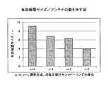
図10に有効被覆サイズ/アンテナ数を表す。図10に示すように、本発明による配備パターンによるアンテナ数あたりの有効被覆サイズは、n = 1のそれを、いずれも上回ることがわかる。 FIG. 10 shows the effective covering size / number of antennas. As shown in FIG. 10, it can be seen that the effective covering size per number of antennas according to the deployment pattern according to the present invention exceeds that of n = 1.
また、既存技術にあげた論文で推奨されたアンテナ配備パターン(n = 4)で有効被覆サイズが最大となるようアンテナ間距離を決定した場合との比較結果を図11に示す。いずれの場合も、有効被覆サイズの点で、本発明が約2倍優位であることがわかる。本発明では、セル中心の配備とアンテナの配備という2段階での配備パターンで効率的な配備パターンを求めるのに対して、同論文での提案では、アンテナ位置をあるパターンで配備するためと考えられる。 FIG. 11 shows a comparison result with the case where the distance between antennas is determined so that the effective covering size is maximized with the antenna deployment pattern (n = 4) recommended in the paper cited in the existing technology. In either case, it can be seen that the present invention is approximately twice as advantageous in terms of effective coating size. In the present invention, an efficient deployment pattern is obtained by a two-stage deployment pattern of cell-centered deployment and antenna deployment, whereas in the proposal in this paper, the antenna position is considered to be deployed in a certain pattern. It is done.
なお、上記の図3に示す最適化装置の各構成要素の動作をプログラムとして構築し、最適化装置として利用されるコンピュータにインストールして実行させる、または、ネットワークを介して流通させることが可能である。 The operation of each component of the optimization device shown in FIG. 3 can be constructed as a program and installed in a computer used as the optimization device for execution, or distributed via a network. is there.
本発明は、上記の実施の形態に限定されることなく、特許請求の範囲内において種々変更・応用が可能である。 The present invention is not limited to the above-described embodiments, and various modifications and applications can be made within the scope of the claims.
1 入力部
3 最適化部
4 出力部
11〜14 アンテナ
21〜24 リモートユニット
31〜34 リンク
41,42 基地局主装置
51 ネットワーク
61 端末
71 固定端末
DESCRIPTION OF SYMBOLS 1
Claims (7)
前記基地局が、n個のアンテナを備え、かつ、当該基地局により構成される通信エリアであるセルの中心と該n個のアンテナが、
座標軸原点をあるセルの中心から別のセルの中心に移しても、また、座標軸を2π/n(nはアンテナ数)回転しても、同じ配備パターンとなることを拘束条件として、任意地点(x,y)での受信電力mn(d1,…,dn)=Kf(l(d1)ν1,…,l(dn)νn)が、目標値v'を確率1−ε以上で満足し、かつ、全平面を最小のセル数で覆う漸近的最小被覆問題を解くことにより導出された最適なセル配置のパターン及びアンテナの配置パターンにより配置される
ことを特徴とする無線通信システム。 A wireless communication system comprising a plurality of base stations using antennas in which one base station is placed at n points,
The base station includes n antennas, and the center of a cell that is a communication area configured by the base station and the n antennas are
Even if the coordinate axis origin is moved from the center of one cell to the center of another cell, and the coordinate axis is rotated by 2π / n (where n is the number of antennas) The received power m n (d 1 ,..., d n ) = Kf (l (d 1 ) ν 1 ,..., l (d n ) ν n ) at x, y) is the probability 1− The radio is characterized by an optimal cell arrangement pattern and antenna arrangement pattern derived by solving an asymptotic minimum covering problem that satisfies ε or more and covers the entire plane with the minimum number of cells. Communications system.
アンテナ数が3(n=3)の場合は、平面を合同な正六角形で分割し、該正六角形の各頂点にセルの中心が配備され、
アンテナ数が4(n=4)の場合は、平面を合同な正方形で分割し、該正方形の各頂点にセルの中心が配備され、
アンテナ数が6(n=6)の場合は、平面を合同な正三角形で分割し、該正三角形の各頂点にセルの中心が配備される
請求項1記載の無線通信システム。 When the number of antennas is 2 (n = 2), the plane is divided into congruent parallelograms, and the center of the cell is arranged at each vertex of the parallelogram,
When the number of antennas is 3 (n = 3), the plane is divided by a congruent regular hexagon, and the center of the cell is arranged at each vertex of the regular hexagon,
When the number of antennas is 4 (n = 4), the plane is divided into congruent squares, and the center of the cell is arranged at each vertex of the squares.
The radio communication system according to claim 1, wherein when the number of antennas is 6 (n = 6), the plane is divided by congruent equilateral triangles, and the center of the cell is arranged at each vertex of the equilateral triangle.
前記最適化装置は、
拘束条件により、任意地点(x,y)での受信電力mn(d1,…,dn)=Kf(l(d1)ν1,…,l(dn)νn)が、目標値v'を確率1-ε以上で満足し、かつ、全平面を最小のセル数で覆う漸近的最小被覆問題を解くことにより、最適なセル配置のパターン及びアンテナの配置パターンを導出する最適化手段を備える
ことを特徴とする最適化装置。 A cell antenna deployment pattern optimizing device for optimizing cell arrangement and antenna arrangement in a wireless communication system composed of a plurality of base stations,
The optimization device includes:
The received power m n (d 1 ,..., D n ) = Kf (l (d 1 ) ν 1 ,..., L (d n ) ν n ) at an arbitrary point (x, y) depends on the constraint condition. Optimization that derives the optimal cell layout pattern and antenna layout pattern by solving the asymptotic minimum coverage problem that satisfies the value v 'with probability 1-ε or more and covers the entire plane with the minimum number of cells An optimization device comprising: means.
前記最適化手段は、
前記入力手段から取得した値に基づいて、セルの中心を頂点とする多角形の一辺に沿った直線と、セル中心と当該セルのアンテナの1つを結ぶ直線のなす角φ∈Φ(n)と、原点に中心を持つセルの境界
Rn((x,y)|→x1(0,0,φ),…,→xn(0,0,φ))=1−ε
(→はベクトルを示す)
上の任意の(x,y)に対して、
Rn((x,y)|→x1(i,j,Fi,j(φ)),…,→xn(i,j,Fi,j(φ)))≧1−ε
を満たす(i,j)が存在することを拘束条件とし、セルの重なりあいを考慮した有効被覆サイズについて、拘束条件付最適化問題を解くことにより、該有効被覆サイズを該拘束条件の下で最大化し、最適なセル配置のパターン及びアンテナの配置パターンを導出する最適パターン導出手段を含む
請求項3記載のセル・アンテナ配備パターン最適化装置。 A function form of the number of antennas n, f, a function form of the path loss function l (d) and a parameter value such as α, a normalized target value v, and a target value non-achievable allowable value ε;
The optimization means includes
Based on the value obtained from the input means, an angle φεΦ (n) formed by a straight line along one side of the polygon having the center of the cell as a vertex and a straight line connecting the cell center and one of the antennas of the cell. And the boundary of the cell centered at the origin
R n ((x, y) | → x 1 (0,0, φ),…, → x n (0,0, φ)) = 1−ε
(→ indicates a vector)
For any (x, y) above,
R n ((x, y) | → x 1 (i, j, F i, j (φ)),…, → x n (i, j, F i, j (φ))) ≧ 1−ε
The constraint condition is that there exists (i, j) that satisfies the above condition, and the effective coverage size is considered under the constraint condition by solving the constrained optimization problem for the effective coverage size considering cell overlap. 4. The cell antenna deployment pattern optimizing device according to claim 3, further comprising an optimum pattern deriving unit for maximizing and deriving an optimum cell arrangement pattern and an antenna arrangement pattern.
前記有効被覆サイズs(n)(pn)を、
で与え、前記pnを調整し、前記有効被覆サイズs(n)(pn)を前記拘束条件の下で、最大化する手段を含む
請求項4記載のセル・アンテナ配備パターン最適化装置。 The optimum pattern derivation means includes:
The effective covering size s (n) (p n ),
The cell antenna deployment pattern optimizing device according to claim 4, further comprising means for adjusting the pn and maximizing the effective covering size s (n) (p n ) under the constraint condition.
前記入力手段は、
アンテナコスト、主要部コスト、または、それらの比を、共用するための条件として更に入力する手段を含み、
前記最適化手段は、
前記共用するための条件が付加された拘束条件に基づいて前記最適化問題の解を求め、得られた解によって定められる位置に前記セルの中心が配置され、前記n個のアンテナが、当該セルの中心を中心とする正n角形の各頂点に配置される配置パターンを導出する手段を含む
請求項4記載のセル・アンテナ配備パターン最適化装置。 When the base station shares the antenna with a base station of a plurality of cells,
The input means includes
Means for further inputting the antenna cost, main part cost, or ratio thereof as a condition for sharing;
The optimization means includes
The solution of the optimization problem is obtained based on the constraint condition to which the condition for sharing is added, the center of the cell is arranged at a position determined by the obtained solution, and the n antennas are connected to the cell. 5. The cell antenna deployment pattern optimizing device according to claim 4, further comprising means for deriving an arrangement pattern arranged at each apex of a regular n-gon centering on the center of the cell.
Priority Applications (1)
| Application Number | Priority Date | Filing Date | Title |
|---|---|---|---|
| JP2011123421A JP5484400B2 (en) | 2011-06-01 | 2011-06-01 | Wireless communication system, cell antenna deployment pattern optimization apparatus, and program |
Applications Claiming Priority (1)
| Application Number | Priority Date | Filing Date | Title |
|---|---|---|---|
| JP2011123421A JP5484400B2 (en) | 2011-06-01 | 2011-06-01 | Wireless communication system, cell antenna deployment pattern optimization apparatus, and program |
Publications (2)
| Publication Number | Publication Date |
|---|---|
| JP2012253496A true JP2012253496A (en) | 2012-12-20 |
| JP5484400B2 JP5484400B2 (en) | 2014-05-07 |
Family
ID=47525912
Family Applications (1)
| Application Number | Title | Priority Date | Filing Date |
|---|---|---|---|
| JP2011123421A Expired - Fee Related JP5484400B2 (en) | 2011-06-01 | 2011-06-01 | Wireless communication system, cell antenna deployment pattern optimization apparatus, and program |
Country Status (1)
| Country | Link |
|---|---|
| JP (1) | JP5484400B2 (en) |
Cited By (1)
| Publication number | Priority date | Publication date | Assignee | Title |
|---|---|---|---|---|
| WO2020179544A1 (en) * | 2019-03-04 | 2020-09-10 | 日本電信電話株式会社 | Wireless base station installation position calculation method and wireless base station installation position calculation device |
Citations (4)
| Publication number | Priority date | Publication date | Assignee | Title |
|---|---|---|---|---|
| JPH08317458A (en) * | 1995-05-19 | 1996-11-29 | Sanyo Electric Co Ltd | Method for deciding installation pattern of phs base station |
| JP2006245827A (en) * | 2005-03-01 | 2006-09-14 | Bb Mobile Corp | Radio communication system and method for forming cell |
| WO2010073293A1 (en) * | 2008-12-22 | 2010-07-01 | 富士通株式会社 | Radio communication system and radio communication method |
| JP2010532630A (en) * | 2007-06-26 | 2010-10-07 | エルジーシー ワイヤレス,インコーポレイティド | Distributed antenna communication system |
-
2011
- 2011-06-01 JP JP2011123421A patent/JP5484400B2/en not_active Expired - Fee Related
Patent Citations (4)
| Publication number | Priority date | Publication date | Assignee | Title |
|---|---|---|---|---|
| JPH08317458A (en) * | 1995-05-19 | 1996-11-29 | Sanyo Electric Co Ltd | Method for deciding installation pattern of phs base station |
| JP2006245827A (en) * | 2005-03-01 | 2006-09-14 | Bb Mobile Corp | Radio communication system and method for forming cell |
| JP2010532630A (en) * | 2007-06-26 | 2010-10-07 | エルジーシー ワイヤレス,インコーポレイティド | Distributed antenna communication system |
| WO2010073293A1 (en) * | 2008-12-22 | 2010-07-01 | 富士通株式会社 | Radio communication system and radio communication method |
Cited By (5)
| Publication number | Priority date | Publication date | Assignee | Title |
|---|---|---|---|---|
| WO2020179544A1 (en) * | 2019-03-04 | 2020-09-10 | 日本電信電話株式会社 | Wireless base station installation position calculation method and wireless base station installation position calculation device |
| JP2020145519A (en) * | 2019-03-04 | 2020-09-10 | 日本電信電話株式会社 | Radio base station installation position calculation method and radio base station installation position calculation apparatus |
| US20220141672A1 (en) * | 2019-03-04 | 2022-05-05 | Nippon Telegraph And Telephone Corporation | Wireless base station installation position calculation method and wireless base station installation position calculation device |
| JP7156093B2 (en) | 2019-03-04 | 2022-10-19 | 日本電信電話株式会社 | Radio base station installation position calculation method and radio base station installation position calculation device |
| US11832112B2 (en) * | 2019-03-04 | 2023-11-28 | Nippon Telegraph And Telephone Corporation | Wireless base station installation position calculation method and wireless base station installation position calculation device |
Also Published As
| Publication number | Publication date |
|---|---|
| JP5484400B2 (en) | 2014-05-07 |
Similar Documents
| Publication | Publication Date | Title |
|---|---|---|
| Mei et al. | Cellular-connected UAV: Uplink association, power control and interference coordination | |
| Chakareski et al. | An energy efficient framework for UAV-assisted millimeter wave 5G heterogeneous cellular networks | |
| US11670863B2 (en) | Multibeam antenna designs and operation | |
| US8718541B2 (en) | Techniques for optimal location and configuration of infrastructure relay nodes in wireless networks | |
| US20040259563A1 (en) | Method and apparatus for sector channelization and polarization for reduced interference in wireless networks | |
| US9648502B2 (en) | System for tailoring wireless coverage to a geographic area | |
| EP2382805B1 (en) | Coordinated multipoint wireless communication | |
| US9629000B2 (en) | Methods and apparatus for antenna elevation design | |
| WO2005020462A2 (en) | Interference based channel selection method in sectorized cells in a wlan | |
| Pang et al. | Intelligent reflecting surface assisted interference mitigation for cellular-connected UAV | |
| Nafees et al. | Multi-tier variable height UAV networks: User coverage and throughput optimization | |
| Firyaguna et al. | Performance analysis of indoor mmWave networks with ceiling-mounted access points | |
| Shang et al. | UAV swarm-enabled aerial reconfigurable intelligent surface: Modeling, analysis, and optimization | |
| George et al. | Enclosed mmWave wearable networks: Feasibility and performance | |
| Lavdas et al. | A machine learning adaptive beamforming framework for 5G millimeter wave massive MIMO multicellular networks | |
| Huang et al. | Non-intrusive cognitive radio networks based on smart antenna technology | |
| Abdelhakam et al. | Efficient WMMSE beamforming for 5G mmWave cellular networks exploiting the effect of antenna array geometries | |
| Kim et al. | Coverage analysis of dynamic coordinated beamforming for LEO satellite downlink networks | |
| JP5484400B2 (en) | Wireless communication system, cell antenna deployment pattern optimization apparatus, and program | |
| US20170318590A1 (en) | Signal transmission method and device | |
| JP2012209715A (en) | Radio communication system and cell/antenna arrangement pattern optimization device and program | |
| Wang et al. | Dense indoor mmWave wearable networks: managing interference and scalable MAC | |
| Hoshino et al. | Improving throughput by multi-cell coordinated vertical plane beam control with pre-coding | |
| Guo et al. | Joint attitude and power optimization for UAV-aided downlink communications | |
| Katsidimas et al. | Placement optimization in wireless charging systems under the vector model |
Legal Events
| Date | Code | Title | Description |
|---|---|---|---|
| A621 | Written request for application examination |
Free format text: JAPANESE INTERMEDIATE CODE: A621 Effective date: 20130626 |
|
| RD02 | Notification of acceptance of power of attorney |
Free format text: JAPANESE INTERMEDIATE CODE: A7422 Effective date: 20131004 |
|
| A977 | Report on retrieval |
Free format text: JAPANESE INTERMEDIATE CODE: A971007 Effective date: 20140131 |
|
| TRDD | Decision of grant or rejection written | ||
| A01 | Written decision to grant a patent or to grant a registration (utility model) |
Free format text: JAPANESE INTERMEDIATE CODE: A01 Effective date: 20140212 |
|
| A61 | First payment of annual fees (during grant procedure) |
Free format text: JAPANESE INTERMEDIATE CODE: A61 Effective date: 20140218 |
|
| R150 | Certificate of patent or registration of utility model |
Ref document number: 5484400 Country of ref document: JP Free format text: JAPANESE INTERMEDIATE CODE: R150 |
|
| LAPS | Cancellation because of no payment of annual fees |