JP2012248965A - Facility control system - Google Patents
Facility control system Download PDFInfo
- Publication number
- JP2012248965A JP2012248965A JP2011117352A JP2011117352A JP2012248965A JP 2012248965 A JP2012248965 A JP 2012248965A JP 2011117352 A JP2011117352 A JP 2011117352A JP 2011117352 A JP2011117352 A JP 2011117352A JP 2012248965 A JP2012248965 A JP 2012248965A
- Authority
- JP
- Japan
- Prior art keywords
- control
- equipment
- stop
- unit
- signal
- Prior art date
- Legal status (The legal status is an assumption and is not a legal conclusion. Google has not performed a legal analysis and makes no representation as to the accuracy of the status listed.)
- Withdrawn
Links
Images


Abstract
Description
本発明は、複数の機器と接続された設備コントローラから送信される指令信号によって空調機などの設備を制御する設備制御システムに関する。 The present invention relates to an equipment control system for controlling equipment such as an air conditioner by a command signal transmitted from an equipment controller connected to a plurality of devices.
従来より、複数の空調空間毎の温度状況に応じて、空調機からの風量を各個に制御するVAV(Variable Air Volume:可変風量)ユニットを有した空調システム(設備制御システム)が知られている。この空調システムでは、室内の温度差が大きい場合には風量を多くするなど、温度差に見合った風量を調整することで室内の温度差を小さくし、設定温度に近づくにつれて徐々に風量を小さくする。これにより、空調機の負担を軽減して、ランニングコストの低減、省エネルギー化を図ることができる。 Conventionally, an air conditioning system (equipment control system) having a VAV (Variable Air Volume) unit that controls the air volume from an air conditioner individually according to the temperature conditions of each of a plurality of air-conditioned spaces is known. . In this air conditioning system, if the temperature difference in the room is large, the air volume is increased by adjusting the air volume corresponding to the temperature difference, and the air volume is gradually decreased as the temperature approaches the set temperature. . Thereby, the burden on the air conditioner can be reduced, and the running cost can be reduced and the energy can be saved.
空調システムは、図6に示すように、例えば、中央監視装置61、コアユニット(設備コントローラ)62、空調機63、及び手元設定器64を備える。ユーザは、中央監視装置61又は手元設定器64を用いて空調機63のON/OFFや設定温度を制御する。コアユニット62に備わるポート1は中央監視装置61、ポート2は手元設定器64と接続される。
As shown in FIG. 6, the air conditioning system includes, for example, a central monitoring device 61, a core unit (equipment controller) 62, an air conditioner 63, and a hand setting device 64. The user controls ON / OFF of the air conditioner 63 and the set temperature using the central monitoring device 61 or the hand setting device 64. The
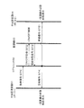
この空調システムの動作に関して図7を参照して説明する。最初に、中央監視装置61は、空調機63への指令である発停信号をコアユニット62に送信し、コアユニット62に備わる発停信号受信部62aは当該発停信号を受信する(S71)。次に、発停信号出力部62bは、当該発停信号に基づいてON/OFF指令を空調機63に送信する(S72)。また、空調機63は、このON/OFF指令を受信した後の現在状態(ON/OFF)信号をコアユニット62に返信する(S73)。
The operation of this air conditioning system will be described with reference to FIG. First, the central monitoring device 61 transmits an on / off signal, which is a command to the air conditioner 63, to the core unit 62, and the on / off
次に、コアユニット2に備わる発停失敗判定処理部62cは、空調機63に対して送信したON/OFF指令と、発停失敗の監視時間内に受信した現在状態(ON/OFF状態)信号の内容が一致しているか否かを判定する。発停失敗判定処理部62cは、一致していない場合には発停失敗と判定し、発停失敗の警報信号を中央監視装置61に送信し(S74)、また手元設定器64にも送信する(S75)。なお、自動制御演算処理部62dは、コアユニット62からの発停信号の出力時を演算する。
Next, the start / stop failure
ところで、ビル内に設置される多数の空気調和機を、ビルの中央監視盤や中央制御装置などの複数箇所から運転制御し監視でき、使い勝手のよい空調管理システムも知られている(例えば、特許文献1参照)。 By the way, many air conditioners installed in a building can be controlled and monitored from a plurality of locations such as a central monitoring panel of a building and a central control device, and an air conditioning management system that is easy to use is also known (for example, patents) Reference 1).
しかしながら、上記従来の空調システムにおいて、コアユニット62には、中央監視装置61や手元設定器64など、空調機63に対する制御情報を送信する機器が複数接続される。この場合、コアユニット62は、どの機器から送信された制御情報に基づいて空調機63の制御を行ったかを監視できない。従って、コアユニット62は、発停失敗判定処理部62cで発停失敗と判定されても、制御情報を発信した制御元となる機器を特定できず、発停失敗の警報信号をシステムに接続された全ての機器に返信するなどしている。
However, in the conventional air conditioning system, the core unit 62 is connected to a plurality of devices that transmit control information for the air conditioner 63 such as the central monitoring device 61 and the hand setting device 64. In this case, the core unit 62 cannot monitor which device has controlled the air conditioner 63 based on the control information transmitted. Accordingly, even if the start / stop failure
本発明は、上記課題に鑑みてなされたものであり、制御情報を発信する機器が設備コントローラに複数接続される場合でも、この設備コントローラにおいて制御元となる機器を判定できるようにした設備制御システムを提供することを目的とする。 The present invention has been made in view of the above problems, and even when a plurality of devices that transmit control information are connected to a facility controller, the facility control system can determine a device that is a control source in the facility controller. The purpose is to provide.
上記目的を達成するために本発明は、設備を制御する設備コントローラと、前記設備コントローラに通信接続され、前記設備を制御するための制御情報を発信する複数の機器と、を備えた設備制御システムにおいて、前記設備コントローラは、前記制御情報を受信する受信手段と、前記受信手段で受信した制御情報に基づいて前記設備に発停信号を出力する発停信号出力手段と、前記制御情報を発信した制御元となる機器を判定する機器判定手段と、前記発停信号出力手段により前記設備に発停信号の出力が行われ、この発停信号の制御内容と、所定の監視時間内に前記設備から取得する状態信号とが一致しない場合、発停失敗と判定する発停失敗判定処理手段と、前記発停失敗と判定された場合、前記機器判定手段において判定された制御元となる機器に警報信号を送信する送信手段とを備える、ことを特徴とするものである。 In order to achieve the above object, the present invention provides an equipment control system comprising: an equipment controller that controls equipment; and a plurality of devices that are communicatively connected to the equipment controller and transmit control information for controlling the equipment. The facility controller transmits the control information, receiving means for receiving the control information, start / stop signal output means for outputting a start / stop signal to the equipment based on the control information received by the receiving means, and the control information. A device determination unit for determining a device as a control source, and a start / stop signal is output to the facility by the start / stop signal output unit, and the control content of the start / stop signal and the facility within a predetermined monitoring time. When the state signal to be acquired does not match, the start / stop failure determination processing means for determining the start / stop failure, and the control determined by the device determination means when the start / stop failure is determined And transmitting means for transmitting a warning signal to the device to be, it is characterized in.
この設備制御システムにおいて、前記機器判定手段は、前記設備コントローラに備わる入力ポート番号により前記制御元となる機器を判定することが好ましい。 In this facility control system, it is preferable that the device determination means determine the device that is the control source based on an input port number provided in the facility controller.
この設備制御システムにおいて、前記受信手段は、前記制御情報をフラグ付きで受信し、前記機器判定手段は、前記フラグにより前記制御元となる機器を判定することが好ましい。 In this facility control system, it is preferable that the receiving unit receives the control information with a flag, and the device determination unit determines the device to be the control source based on the flag.
この設備制御システムにおいて、前記送信手段は、前記警報信号を、前記制御元となる機器以外の機器にも送信することが好ましい。 In this equipment control system, it is preferable that the transmission means transmits the alarm signal to a device other than the device that is the control source.
本発明によれば、設備コントローラは、制御情報を発信した制御元となる機器を判定する機器判定部を備える。このため、制御元となる機器が設備コントローラに複数接続される場合でも、設備コントローラの機器判定部において制御元となる機器を判定でき、警報信号などを制御元となる機器に確実に送信できる。 According to this invention, an equipment controller is provided with the apparatus determination part which determines the apparatus used as the control origin which transmitted control information. Therefore, even when a plurality of control source devices are connected to the facility controller, the device determination unit of the facility controller can determine the control source device and reliably transmit an alarm signal or the like to the control source device.
(実施の形態1)
本発明の設備制御システムを空調システムに適用した実施の形態1について図面を参照して説明する。図1の空調システムSは、オフィスビルの空調設備の監視・制御などに使用され、中央監視装置1と、コアユニット2と、VAVコントローラ3と、設定器4と、VAVユニット5と、空調機6、I/O7と、手元設定器8とを備える。なお、各機器はバス10を介して通信接続される。
(Embodiment 1)
中央監視装置1は、空調システムSを集中管理するためのデスクトップ型や壁掛型のコンピュータである。この中央監視装置1は、空調機6からコアユニット2に送られた状態(ON/OFF)信号、警報信号、室内温度、風量等のデータを、バス10を介して取得し画面表示する。また、中央監視装置1は、空調機6に与える発停信号や設定温度等の指令データを、バス10を介してVAVコントローラ3に送信する。ユーザは、空調機6の作動状態を、中央監視装置1の画面表示を介して監視し、各種設定値を変更できる。
The
コアユニット(設備コントローラ)2は、空調制御用のコントローラであり、通信接続された中央監視装置1及び手元設定器8から送信される空調機6の制御信号を受信し、この制御信号に基づいて空調機6に発停信号、設定温度などの指令データを送信する。また、コアユニット2は、各種入出力端末器を組み合わせることで、制御対象となる空調機6に応じて任意にI/O7を選択・拡張する機能を有する。さらに、コアユニット2は、VAVコントローラ3と直接通信を行い、VAVユニット5との連動制御も可能とする。
The core unit (equipment controller) 2 is a controller for air conditioning control, and receives a control signal of the air conditioner 6 transmitted from the
VAVコントローラ3は、VAVユニット5に取り付けて使用され、風速センサの検出値や温度センサで検出された室内計測温度より各空調空間に対する要求風量を演算して、VAVユニット5のダンパの開度を調整して風量制御を行う。
The
設定器4は、VAVコントローラ3に信号線などで通信接続され、VAVユニット5の制御を行う際に使用される室内用リモコンであり、例えばVAVユニット5の発停(入切)や温度設定の操作入力が可能である。設定器4は、VAVユニット5の入切状態や運転表示・室内温度表示などを液晶画面表示する。
The
VAVユニット5は、ダクト9を介して空調機6と接続される。このVAVユニット5は、ダクト9に取り付けられて各空調空間の風量を可変制御するためのダンパを備え、VAVコントローラ3から受信する開閉指令信号に基づいてダンパの開度を調整して各空調空間の温度を調整する。ダクト9には、風量調節手段としてのVAVユニット5が設けられ、VAVユニット5を通して風量調節された空気が空調空間に吹き出される。
The VAV unit 5 is connected to the air conditioner 6 through a duct 9. This VAV unit 5 is provided with a damper attached to the duct 9 for variably controlling the air volume of each air-conditioned space, and adjusts the opening degree of the damper based on an open / close command signal received from the
空調機6は、モータによって回転駆動させる送風機、熱交換器やインバータなどを備え、ダクト9を通して建物の複数の空調空間に冷気や暖気を給気する。空調機6は、コアユニット2と通信接続され、発停指令、ファン回転数の指令や温度指令などの指令データを受ける。I/O7は、コアユニット2と空調機6との間に配置され、コアユニット2に接続される入出力端末器である。
The air conditioner 6 includes a blower that is rotationally driven by a motor, a heat exchanger, an inverter, and the like, and supplies cool air and warm air to a plurality of air-conditioned spaces of the building through the duct 9. The air conditioner 6 is communicably connected to the
手元設定器8は、空調機6に接続され、例えば空調機6の発停(入切)や温度設定の操作入力が可能となる。手元設定器8は、空調機6から送信された現在状態信号に基づいて、空調機6の入切状態や運転表示・室内温度表示などをLEDや液晶の画面で表示する。
The hand setting
次に、本実施の形態1に係る空調システムSのコアユニット2の機能構成に関して図2を参照して説明する。コアユニット2は、CPU21内に自動制御演算処理部2a、送受信部2b、発停信号出力部2c、発停失敗判定処理部2d、及び機器判定部2eを備え、コアユニット2のポート1は中央監視装置1、ポート2は手元設定器8に接続される。
Next, the functional configuration of the
自動制御演算処理部2aは、各空調空間の温度を調節するための演算を行い、必要に応じて空調機6に発停信号の指令を実行する。送受信部2bは、ポート1に接続された中央監視装置1又はポート2に接続された手元設定器8から発停信号を受信すると共に、警報信号や状態信号を中央監視装置1及び手元設定器8に送信する。発停信号出力部2cは、送受信部2bで受信した発停信号に基づいて、空調機6にON/OFF指令信号を出力する。発停失敗判定処理部2dは、空調機6に送信したON/OFF指令と、空調機6から所定期間内である監視時間内に受信する現在状態(ON/OFF)信号とを比較し、ON/OFF状態が一致しない場合には、発停失敗と判定する。機器判定部2eは、制御情報を受信した入力ポート番号により空調機6の制御情報を発信した制御元となる機器を判定する。すなわち、機器判定部2eは、制御情報を発信したのが中央監視装置1又は手元設定器8のいずれとなるかを判定する。
The automatic control
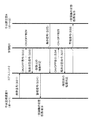
次に、本実施の形態1に係る空調システムSの動作に関して図3を参照して説明する。最初に、中央監視装置1は、空調機6を開閉制御するための発停信号をコアユニット2に送信する(S31)。そして、コアユニット2は、当該発停信号に基づくON/OFF指令を空調機6に送信し(S32)、空調機6から所定の監視期間内に現在状態信号を受信する(S33)。この監視期間内において、空調機6は、指令に基づいてON/OFF制御を行うと共に、現在状態をコアユニット2に送信する。
Next, the operation of the air conditioning system S according to the first embodiment will be described with reference to FIG. First, the
次に、コアユニット2の機器判定部2eは、発停信号を受信した入力ポート番号に基づいて制御元となる機器を判定する。この場合、機器判定部2eは、S31に示す発停信号をコアユニット2に送信したポート番号1の中央監視装置1を制御元の機器と判定する。そして、コアユニット2は、発停失敗判定処理部2dにおいて送信したON/OFF指令と空調機6の現在状態(ON/OFF)とが一致しない発停失敗と判定される場合、警報信号を中央監視装置1に送信する(S34)。その後、中央監視装置1は、空調機6の異常状態を画面表示する。
Next, the
また、手元設定器8が発停信号をコアユニット2に送信した場合においては(S35)、コアユニット2は、当該発停信号に基づくON/OFF指令を空調機6に送信する(S36)。そして、コアユニット2は、空調機6から所定の監視期間内に現在状態信号を受信する(S37)。次に、コアユニット2の機器判定部2eは、発停信号を受信した入力ポート番号に基づいて制御元となる機器を判定する。この場合、機器判定部2eは、S37において発停信号をコアユニット2に送信したポート番号2の手元設定器8を制御元の機器と判定する。そして、コアユニット2は、発停失敗判定処理部2dにおいて発停失敗と判定される場合、警報信号を手元設定器8に送信し(S38)、手元設定器8は、空調機6の異常状態を表示する。
When the
以上のように、本実施の形態1に係る空調システムSにおいて、コアユニット2の機器判定部2eは、空調機6の制御情報(発停信号)を発信する機器が複数ある場合にも、ポート番号に基づいて制御元の機器を特定することができる。そして、コアユニット2は、発停失敗判定処理部2dにおいて発停失敗と判定される場合、警報信号を機器判定部2eで判定された制御元の機器に送信でき、機器を操作したユーザは空調機6の状態を常に監視できる。
As described above, in the air conditioning system S according to the first embodiment, the
(実施の形態2)
本発明の本実施の形態2について、図4及び図5を参照して説明する。なお、上記実施の形態1に係る空調システムSと同様の構成には同符号を付し、その詳細な説明は省略する。
(Embodiment 2)
The second embodiment of the present invention will be described with reference to FIGS. In addition, the same code | symbol is attached | subjected to the structure similar to the air conditioning system S which concerns on the said
上記実施の形態1に係るコアユニット2は、1つのポートに1つの機器が接続されている。しかし、1つのポートに複数の機器が接続されることもある。本実施の形態2では、コアユニット2の1つのポートに複数の機器が接続される場合において、コアユニット2に送信される制御情報に機器を判別するためのフラグ情報を付加し、コアユニット2は、当該フラグに基づいて制御元の機器を特定することを特徴とする。
In the
ここで、中央監視装置1から送信される発停信号のデータに関して図4を参照して説明する。コアユニット2の送受信部2bは、発停信号情報40にフラグ情報41が付加された発停信号を受信する。図4(a)は、ポート1に接続された中央監視装置1からの制御信号、図4(b)は、ポート2に接続された手元設定器8からの制御信号、図4(c)は、自動制御演算処理部2aからの制御信号である。図4(d)は、ポート1に接続された中央監視装置1以外の機器からの制御信号である。機器判定部2eは、フラグ情報41に基づいて、制御元となる機器を特定することができる。
Here, the data of the start / stop signal transmitted from the
また、発停失敗判定処理部2dは、発停信号出力部2cにより空調機6に発停信号の出力が行われ、この発停信号の制御(ON/OFF)内容と、監視時間内に空調機6から取得した状態(ON/OFF)信号とが一致しない場合、発停失敗と判定する。この場合、送受信部2bは、警報信号として、図4(e)に示す警報信号情報42に制御元となる機器のフラグ情報43を付加して送信する。そして、この警報信号を中央監視装置1に送信することで、中央監視装置1は、制御元となる機器が特定された発停失敗の警報を画面表示できる。
In addition, the start / stop failure
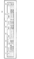
ここで、中央監視装置1の画面表示例を、図5を参照して説明する。中央監視装置1の画面50には、例えば、ポート番号51、ホスト名52、オペレータ名53、日時54、種別A55、種別B56、履歴データ57、及び状態58が表示される。ホスト名52は、「中央監視装置」などポートに接続された機器の名称である。オペレータ名53は、「手元操作」などのユーザ操作名である。種別A55は、中央監視装置1が受信した信号の種別であり、コアユニット2から受信した警報信号の場合には「警報記録」と表示される。種別B56には、種別A55の内容が表示され、空調機6への発停指令と空調機6から受信した現在状態信号が不一致であることを示す「状態不一致」などが表示される。状態58は、現時点での空調機6の制御状態が表示され、状態不一致から復旧した場合には「復旧」、状態不一致が発生し復旧していない場合には「発生」と表示される。
Here, a screen display example of the
以上のように、本実施の形態2において、コアユニット2の機器判定部2eは、発停信号情報40に付加されたフラグ情報41を用いて、同一ポートで複数の異なる機器からの制御情報(発停信号)を受信する場合においても、制御元の機器を確実に判定できる。また、中央監視装置1は、フラグ情報43が付加された警報信号情報42を受信することで、制御元となる機器が特定された発停失敗の警報を画面表示してユーザに確実に警告できる。
As described above, in the second embodiment, the
なお、上記実施の形態1及び2において、送受信部2bは、発停失敗の警報信号を、制御元の機器以外の機器にも送信できる。この場合、コアユニット2は、警報信号などを、中央監視装置1などの画面表示できる機器に確実に送信でき、ユーザに警告できる。
In the first and second embodiments, the transmission /
また、本発明は、上記実施の形態の構成に限られず、発明の趣旨を変更しない範囲で種々の変形が可能である。例えば、本設備制御システムは空調システムに限定されるものではなく、照明制御を行う照明システムなどにも同様に適用できる。また、本設備制御システムにおいて、中央監視装置1や手元設定器8からコアユニット2に送信される情報は、発停信号に限定されるものではなく、温度設定など他の情報でも同様の制御を実現できる。
Further, the present invention is not limited to the configuration of the above-described embodiment, and various modifications can be made without departing from the spirit of the invention. For example, this equipment control system is not limited to an air conditioning system, but can be similarly applied to an illumination system that performs illumination control. In this equipment control system, the information transmitted from the
1 中央監視装置(機器)
2 コアユニット(設備コントローラ)
2a 自動制御演算処理部
2b 送受信部(送信手段及び受信手段)
2c 発停信号出力部
2d 発停失敗判定処理部
2e 機器判定部
3 VAVコントローラ
4 設定器
5 VAVユニット
6 空調機(設備)
7 I/O
8 手元設定器(機器)
9 ダクト
S 空調システム(設備制御システム)
1 Central monitoring device (equipment)
2 Core unit (equipment controller)
2a Automatic control
2c Start / stop
7 I / O
8 Hand setting device (equipment)
9 Duct S Air conditioning system (equipment control system)
Claims (4)
前記設備コントローラは、
前記制御情報を受信する受信手段と、
前記受信手段で受信した制御情報に基づいて前記設備に発停信号を出力する発停信号出力手段と、
前記制御情報を発信した制御元となる機器を判定する機器判定手段と、
前記発停信号出力手段により前記設備に発停信号の出力が行われ、この発停信号の制御内容と、所定の監視時間内に前記設備から取得する状態信号とが一致しない場合、発停失敗と判定する発停失敗判定処理手段と、
前記発停失敗と判定された場合、前記機器判定手段において判定された制御元となる機器に警報信号を送信する送信手段とを備える、ことを特徴とする設備制御システム。 In an equipment control system comprising: an equipment controller that controls equipment; and a plurality of devices that are communicatively connected to the equipment controller and transmit control information for controlling the equipment,
The facility controller is
Receiving means for receiving the control information;
A start / stop signal output means for outputting a start / stop signal to the equipment based on the control information received by the receiving means,
A device determination means for determining a device as a control source that has transmitted the control information;
When the start / stop signal is output to the equipment by the start / stop signal output means, and the control content of the start / stop signal does not match the status signal acquired from the equipment within a predetermined monitoring time, the start / stop failure occurs. Start / stop failure determination processing means for determining,
A facility control system comprising: a transmission unit configured to transmit an alarm signal to a device serving as a control source determined by the device determination unit when the start / stop failure is determined.
前記機器判定手段は、前記フラグにより前記制御元となる機器を判定する、ことを特徴とする請求項1記載の設備制御システム。 The receiving means receives the control information with a flag,
The equipment control system according to claim 1, wherein the device determination unit determines a device serving as the control source based on the flag.
Priority Applications (1)
| Application Number | Priority Date | Filing Date | Title |
|---|---|---|---|
| JP2011117352A JP2012248965A (en) | 2011-05-25 | 2011-05-25 | Facility control system |
Applications Claiming Priority (1)
| Application Number | Priority Date | Filing Date | Title |
|---|---|---|---|
| JP2011117352A JP2012248965A (en) | 2011-05-25 | 2011-05-25 | Facility control system |
Publications (1)
| Publication Number | Publication Date |
|---|---|
| JP2012248965A true JP2012248965A (en) | 2012-12-13 |
Family
ID=47469033
Family Applications (1)
| Application Number | Title | Priority Date | Filing Date |
|---|---|---|---|
| JP2011117352A Withdrawn JP2012248965A (en) | 2011-05-25 | 2011-05-25 | Facility control system |
Country Status (1)
| Country | Link |
|---|---|
| JP (1) | JP2012248965A (en) |
Cited By (2)
| Publication number | Priority date | Publication date | Assignee | Title |
|---|---|---|---|---|
| WO2017013756A1 (en) * | 2015-07-22 | 2017-01-26 | 三菱電機株式会社 | Air-conditioning management apparatus |
| JP2018036938A (en) * | 2016-09-01 | 2018-03-08 | アズビル株式会社 | Facility management system, facility management device, controller, and facility management method |
-
2011
- 2011-05-25 JP JP2011117352A patent/JP2012248965A/en not_active Withdrawn
Cited By (2)
| Publication number | Priority date | Publication date | Assignee | Title |
|---|---|---|---|---|
| WO2017013756A1 (en) * | 2015-07-22 | 2017-01-26 | 三菱電機株式会社 | Air-conditioning management apparatus |
| JP2018036938A (en) * | 2016-09-01 | 2018-03-08 | アズビル株式会社 | Facility management system, facility management device, controller, and facility management method |
Similar Documents
| Publication | Publication Date | Title |
|---|---|---|
| US9810445B2 (en) | Air-conditioning system | |
| JP6253675B2 (en) | Air conditioner trial run application and air conditioner trial run system | |
| EP1610069B1 (en) | Air conditioning system and method for controlling the same | |
| US20170082309A1 (en) | Air-conditioning system | |
| US20150277407A1 (en) | Location detection of control equipment in a building | |
| CN104034998A (en) | Diagnostic method and diagnostic system for mistaken line connection of indoor and outdoor units of fixed frequency air conditioners | |
| GB2520809A (en) | Fan controller | |
| EP2639665A2 (en) | Air-conditioning system | |
| JP2011242004A (en) | Operation check device of air conditioner | |
| WO2016060836A1 (en) | System and method for monitoring and controlling heating, ventilating, and air conditioning equipment | |
| JP2012248965A (en) | Facility control system | |
| JP2008249172A (en) | Air-conditioning control system | |
| EP4060244A1 (en) | Failure detection and compensation in heating, ventilation and air conditioning (hvac) equipment | |
| WO2014188574A1 (en) | Air-conditioning system | |
| WO2017145583A1 (en) | Receiver and air-conditioning device equipped with same | |
| JP6964797B2 (en) | Air conditioning system and air conditioning management system | |
| JP2002031391A (en) | Communication device between different models of centralized control system | |
| JP6687063B2 (en) | Ventilation system | |
| JP6458596B2 (en) | Protocol converter | |
| KR102155558B1 (en) | Air-conditioner and method | |
| JP5849247B2 (en) | Air conditioning system | |
| US20240133570A1 (en) | Hvac sensor information and sensor communication over relay-controlled power line | |
| KR101966950B1 (en) | Multi type air conditioner and controlling method for the same | |
| WO2020066012A1 (en) | Air conditioning management device, air conditioning device, and program for device management method | |
| KR101852824B1 (en) | Control method of air conditioning apparatus |
Legal Events
| Date | Code | Title | Description |
|---|---|---|---|
| A300 | Withdrawal of application because of no request for examination |
Free format text: JAPANESE INTERMEDIATE CODE: A300 Effective date: 20140805 |